- Table of Contents
- Related Documents
-
| Title | Size | Download |
|---|---|---|
| 01-Text | 1.35 MB |
Determining the installation position
Mounting the AP on a junction box
Connecting the AP to a power source
Connecting the AP to the network
Verifying network connectivity when the AP operates in fit mode
Verifying network connectivity when the AP operates in cloud mode
Logging in to the AP from the console port
Connecting the AP to a configuration terminal from the console port
Setting parameters for the configuration terminal
Logging in to the AP through Telnet
Logging in from the Web interface
4 Configuring the AP from the Cloudnet platform
Downloading and installing Cloudnet App Int
1 Preparing for installation
Safety recommendations
|
|
WARNING! Only designated authorized technical personnel can install and remove the AP and its accessories. You must read all safety instructions carefully before working with the AP. |
To avoid possible bodily injury and equipment damage, read the following safety recommendations before installing the AP. Note that the recommendations do not cover every possible hazardous condition.
· To avoid bodily injury and device damage, take adequate safety measures.
· Place the AP in a dry and flat location and take anti-slip measures.
· Keep the AP clean and dust-free.
· Do not place the AP in a moist area and avoid liquid intrusion.
· Keep the AP and installation tools away from walkways.
Site preparation
To ensure that the AP will operate in a favorable environment, examine the installation site before installing the AP. Make sure the temperature and humidity at the installation site meet the requirements in Table1-1.
Table1-1 Temperature and humidity requirements
|
Item |
Specification |
|
Operating temperature |
0°C to 40°C (32°F to 104°F) |
|
Storage temperature |
–40°C to +70°C (–40°F to +158°F) |
|
Operating humidity |
5% RH to 95% RH, noncondensing |
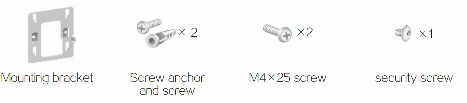
Installation accessories
Figure1-1 Accessories provided with the AP
Installation tools
When installing the AP, you might need the following tools. Prepare the installation tools yourself as required.
Figure1-2 Installation tools

2 Installing the AP
Installation flowchart
Figure2-1 Installation flowchart
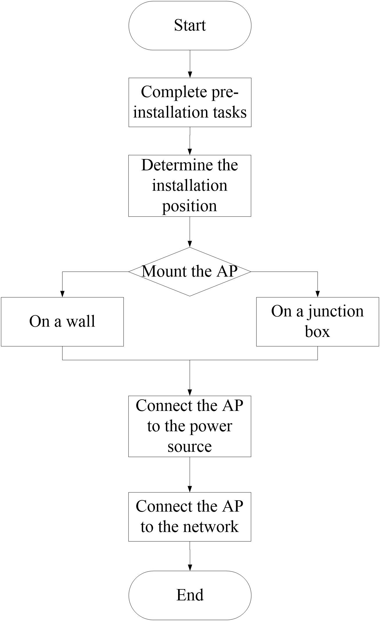
Pre-installation tasks
Before installing the AP, perform the following tasks:
· Power on the AP and connect the AP to the network. Examine the LEDs to verify that the AP is operating correctly. For information about the LEDs, see "LEDs."
· Record the MAC address and serial number of the AP for future use.
Determining the installation position
Determine the installation position by observing the following principles:
· Few obstacles such as wall exist between the AP and clients.
· Reserve clearance around the AP for heat dissipation. Ensure a minimum distance of 2 m (6.56 ft) between the AP and other radiant resources, for example, wireless base station antennas.
· The AP does not hinder people’s daily work and life.
· The place is not water seeping, water soaking, or condensing.
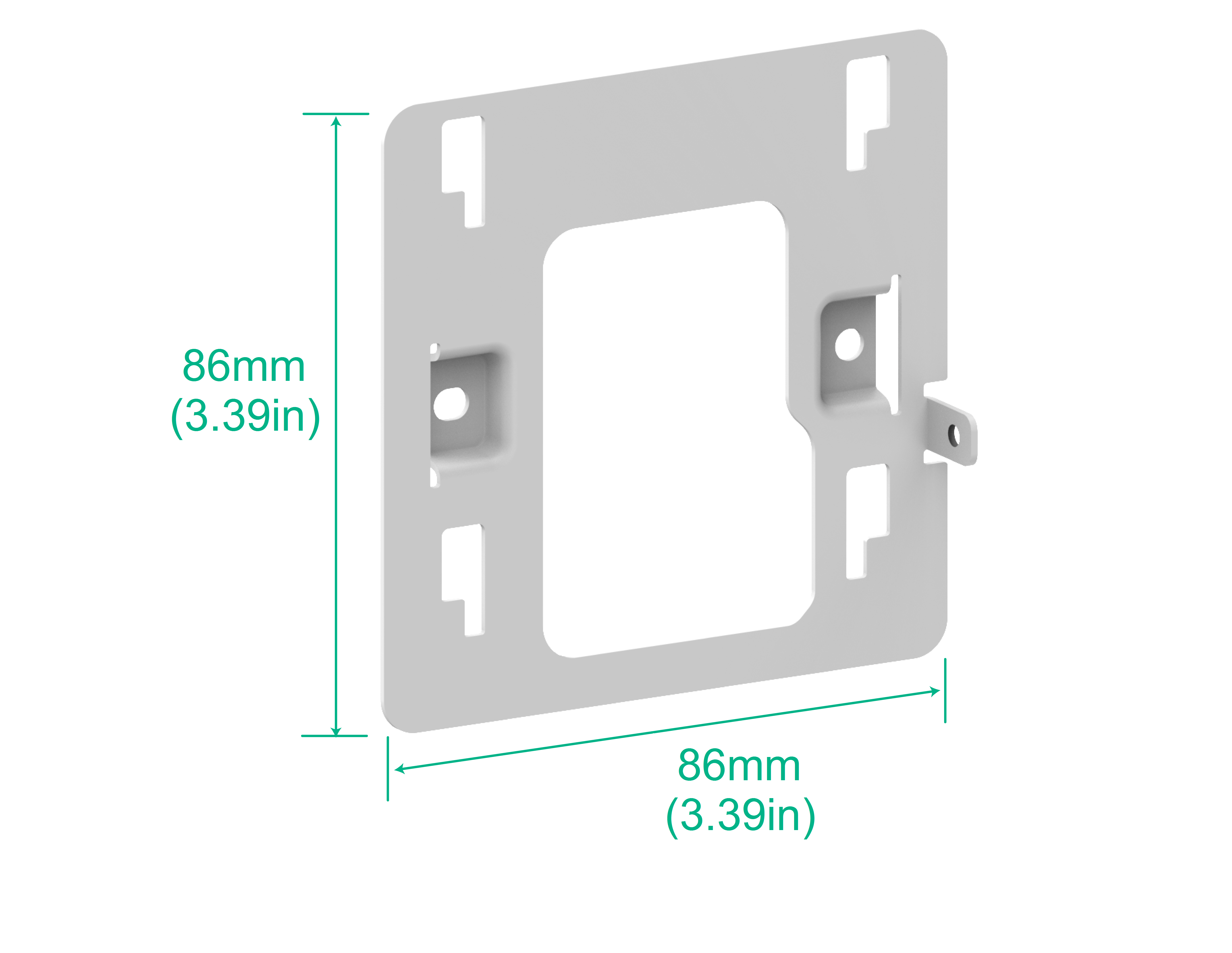
Mounting the AP
The AP can be installed only indoors. You can mount the AP on a wall or a junction box.
Figure2-2 Mounting bracket dimensions
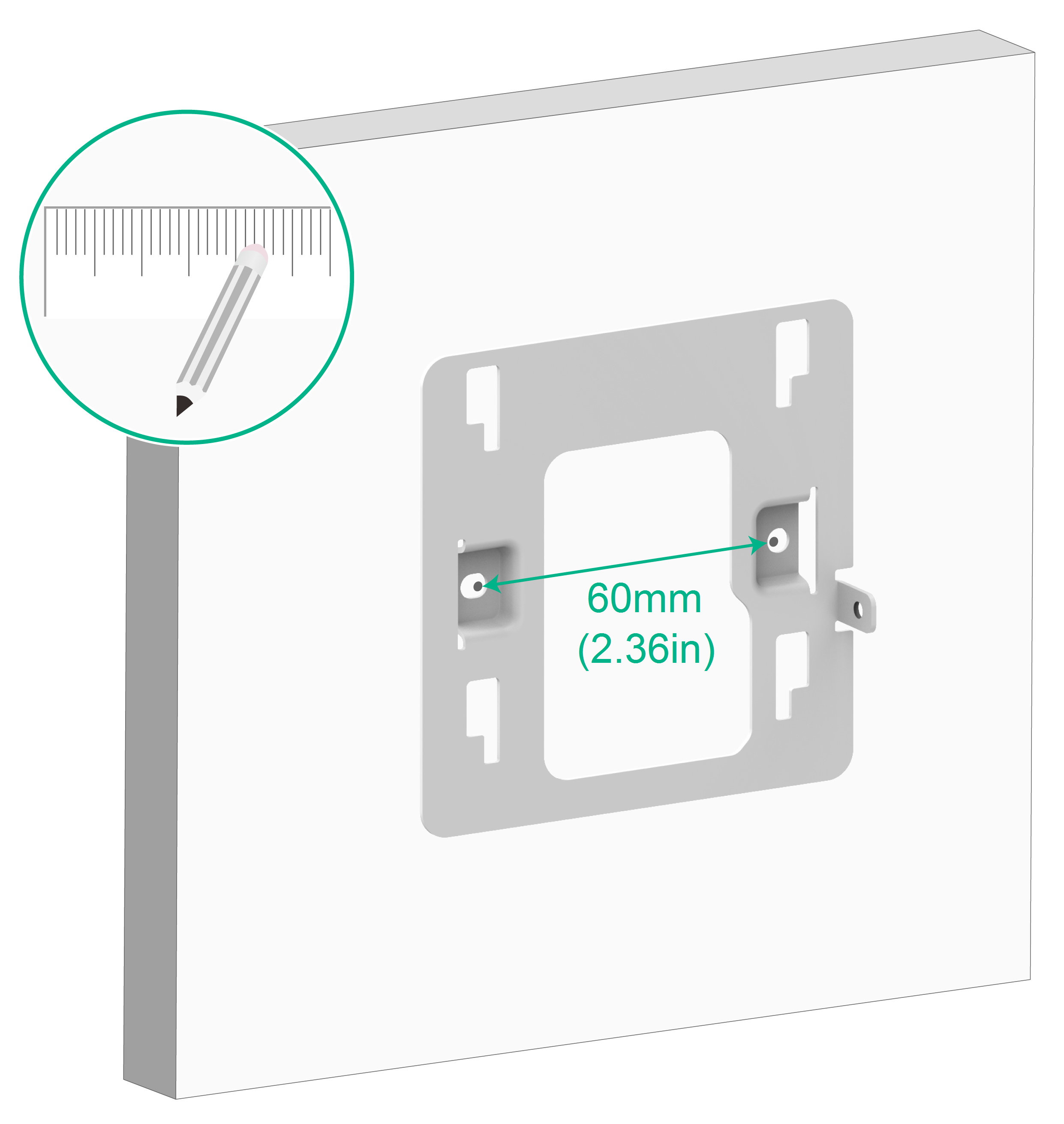
Mounting the AP on a wall
1. Place the mounting bracket against the wall and mark the installation holes on the wall.
Figure2-3 Marking the installation holes on the wall
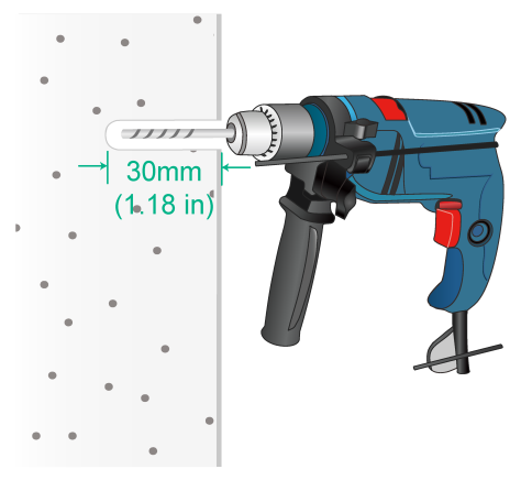
2. Drill two holes with a diameter of 6 mm (0.24 in) and a depth of 30 mm (1.18 in) at the marked locations, as shown in Figure2-4.
Figure2-4 Drilling holes in the wall
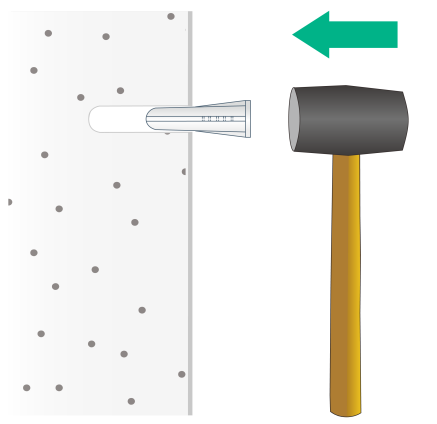
3. Use a rubber hammer to tap a screw anchor into each hole until it is all flush with the wall surface, as shown in Figure2-5.
Figure2-5 Hammering the screw anchor into the wall
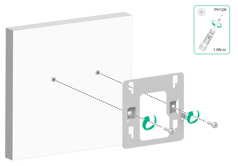
4. Insert the screws through the installation holes in the mounting bracket into the holes in the wall. Fasten the screws to secure the mounting bracket to the wall, as shown in Figure2-6.
Figure2-6 Securing the mounting bracket to the wall
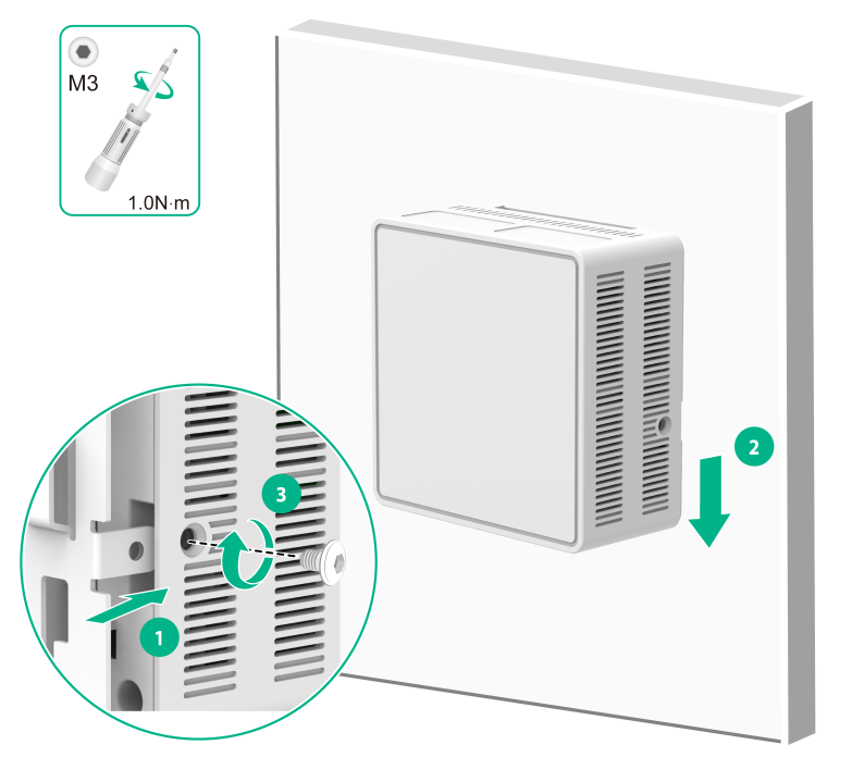
5. Align the device mounting holes with the protruding parts of the mounting bracket, and press the AP down to secure it to the mounting bracket. Then, fasten the M3×4 screws on the sides of the AP, as shown in Figure2-7.
Figure2-7 Securing the AP to the mounting bracket
Mounting the AP on a junction box
1. Use the provided M4 × 30 mm pan-head screws to attach the mounting bracket to the junction box.
Figure2-8 Attaching the mounting bracket to the junction box
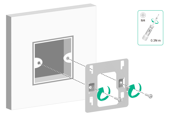
2. Attach the AP to the mounting bracket. The procedure is the same as wall mounting and junction box mounting. For more information, see "Mounting the AP on a wall."
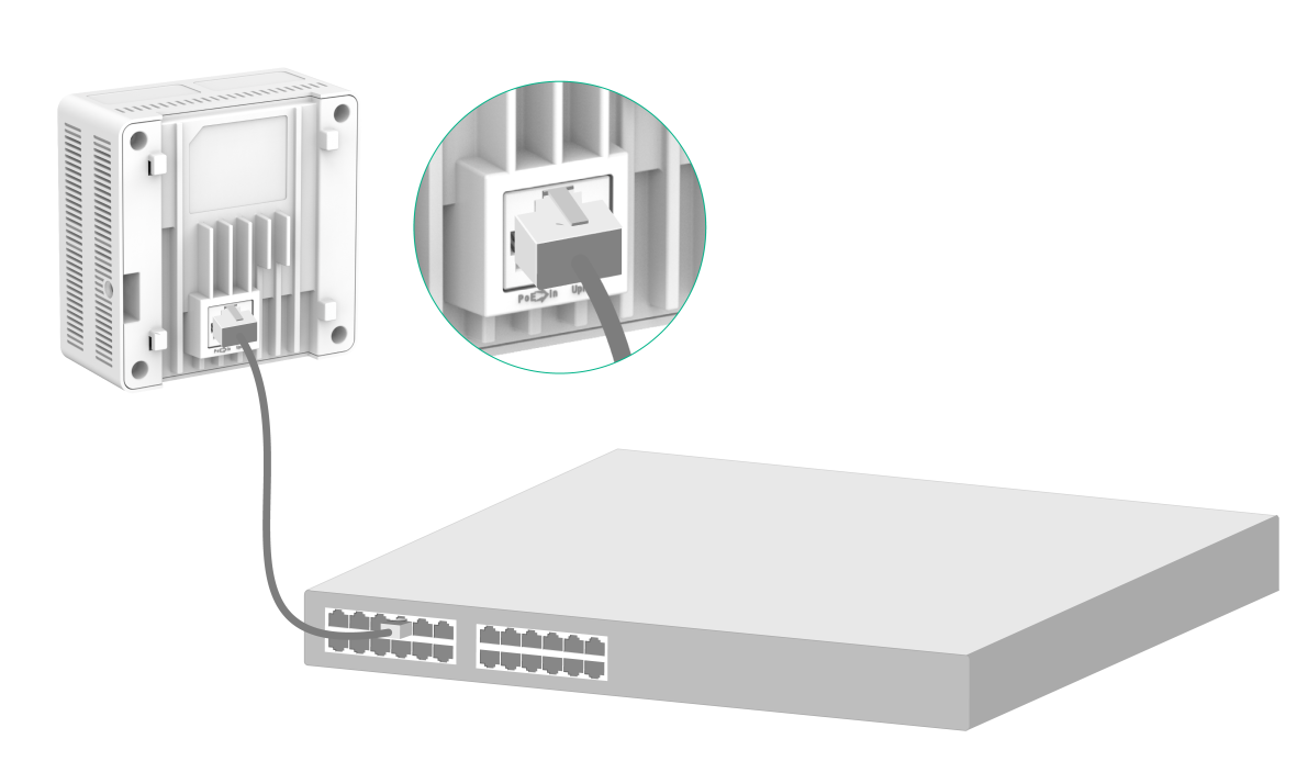
Connecting the AP to a power source
The AP supports only 802.3af-compliant PoE power supply.
Connecting a PoE power source
To power the AP through PoE, use an Ethernet cable to connect an Ethernet port on a PoE switch to the Uplink/PoE port on the AP.
Figure2-9 Connecting the AP to a PoE power source
Check after power-on
Examine the LEDs on the AP after you power on it to verify that the AP is operating correctly. For more information about the LEDs, see "LEDs."
Connecting the AP to the network
Verifying network connectivity when the AP operates in fit mode
When the AP operates in fit mode, all AP settings are configured on the AC. To verify network connectivity of the AP, execute the display wlan ap all command on the AC. If the AP status is R/M, the AP has been connected to the network.
<AC> display wlan ap all
Total number of APs: 1
Total number of connected APs: 1
Total number of connected manual APs: 1
Total number of connected auto APs: 0
Total number of connected common APs: 1
Total number of connected WTUs: 0
Total number of inside APs: 0
Maximum supported APs: 3072
Remaining APs: 3071
Total AP licenses: 128
Remaining AP licenses: 127
AP information
State : I = Idle, J = Join, JA = JoinAck, IL = ImageLoad
C = Config, DC = DataCheck, R = Run M = Master, B = Backup
AP name AP ID State Model Serial ID
ap1 1 R/M WA7322H-HI 219801A5BG8246E00001
Verifying network connectivity when the AP operates in cloud mode
When the AP operates in cloud mode, use a wireless terminal to search for and access the wireless service provided by the AP. If you can access external networks, the AP has been connected to the network.
3 Accessing the AP
When the AP operates in cloud mode, you can access and configure the AP from the console port, Web interface, or through Telnet. Accessing the AP from the Web interface or through Telnet requires the IP address of the AP.
Logging in to the AP from the console port
Prepare the following items for accessing the AP from the console port:
· Console cable: A micro USB-to-USB cable with a micro-USB connector at one end and a USB connector at the other end.
· Configuration terminal: A character terminal with a standard USB interface or a regular PC.
Connecting the AP to a configuration terminal from the console port
|
CAUTION: · When connecting a PC and the device, first connect the USB end of the configuration cable to the PC, and then connect the micro-USB end to the device console port. · When disconnecting, first unplug the micro-USB end and then the USB end. |
Power on the device, connect the USB connector of the cable to the USB port of the PC, and then connect the micro-USB plug to the device console port.
Confirm that the configuration is correct. Under normal circumstances, the device startup information will be displayed on the configuration terminal.
Setting parameters for the configuration terminal
To configure and manage the AP from the console port, you must run a terminal emulator program, such as HyperTerminal or PuTTY, on your configuration terminal. You can use the emulator program to connect a network device, a Telnet site, or an SSH site. For more information about the terminal emulator programs, see the user guides for these programs.
Configure the terminal parameters as follows:
· Bits per second—9600.
· Data bits—8.
· Stop bits—1.
· Parity—None.
· Flow control—None.
Procedure
Verify that the AP is connected correctly to the configuration terminal and the configuration terminal parameters are configured correctly. Then, power on the AP. You can see the following information on the configuration terminal:
System is starting...
Booting Normal Extend BootWare.
...
System application is starting...
Startup configuration file does not exist.
User interface con0 is available.
Press ENTER to get started.
Logging in to the AP through Telnet
By default, Telnet is enabled and the following login information is defined for your login:
· Username—admin.
· Password—h3capadmin.
Cloud mode
Make sure the PC obtains an IP address dynamically.
When the AP operates in cloud mode, it obtains the IP address of VLAN 1 dynamically by default.
To log in to the AP through a wireless connection:
1. Enable WLAN on the configuration terminal and access WLAN H3C_xxxxxx, where xxxxxx is the last six bits of the AP's MAC address.
2. Enter telnet wlan.h3c.com from the CLI of the terminal.
3. Enter the default username and password and change the default password as prompted.
Anchor ACmode
Make sure the PC and AP are on the same network.
To log in to the AP through a wired connection:
1. Enter the default IP address for accessing the device through Telnet: 192.168.0.50. If the default IP address has been changed, contact the administrator to get the new IP address.
2. Enter the default username and password and change the default password as prompted.
Logging in from the Web interface
By default, HTTP and HTTPS are enabled and the following login information is defined for your login:
· Username—admin.
· Password—h3capadmin.
Cloud mode
Make sure the PC obtains an IP address dynamically.
When the AP operates in cloud mode, it obtains the IP address of VLAN 1 dynamically by default.
To log in to the AP through a wireless connection:
1. Enable WLAN on the configuration terminal and access WLAN H3C_xxxxxx, where xxxxxx is the last six bits of the AP's MAC address.
2. Visit http://wlan.h3c.com from a browser, and then press Enter.
3. Enter the default username and password. For security purposes, change the password as prompted after you access the Web interface, and then click OK.
Anchor ACmode
Make sure the PC and AP are on the same network.
To log in to the AP from the Web interface:
1. Enter the default IP address for accessing the device from the Web interface: 192.168.0.50. If the default IP address has been changed, contact the administrator to get the new IP address.
2. Enter the default username and password, and then click Log In. Change the default password as prompted, and then click OK.
.
4 Configuring the AP from the Cloudnet platform
You can manage the AP remotely from the Cloudnet platform (Web interface or app) only when the AP operates in cloud mode.
Downloading and installing Cloudnet App Int
Make sure the smartphone uses Android 4.0, iOS7.0, or a higher-version operating system.
Download and install Cloudnet App Int from Google Play Store.
Logging in to the Cloudnet platform
To manage the AP from the Cloudnet platform, make sure the AP uses an IP address that can reach the external network.
To log in to the Cloudnet platform:
1. Open Cloudnet App Int or visit https://oasiscloudnet.h3c.com from a browser.
2. Enter the username and password.
After login, you can add the AP to the platform and manage the AP. For more information about platform login and device management, see H3C Cloudnet Deployment Guide.
5 Appendix A Ports and LEDs
Ports
Figure5-1 WA7322H-HI
The AP provides the following ports:
· One console port
· Four 10/100/1000M Ethernet copper ports
· One Uplink/PoE port
· One USB port
It provides also a reset button (RST).
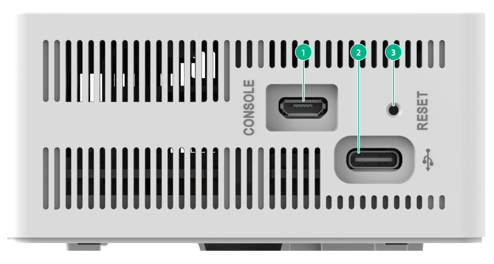
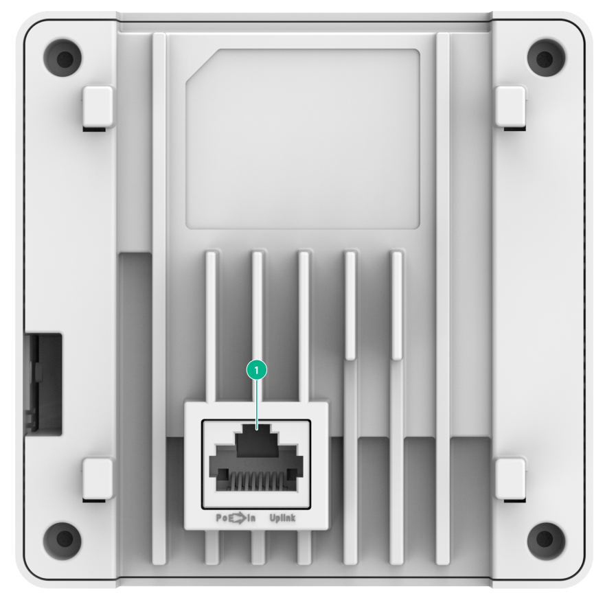
Figure5-2 Ports on the AP
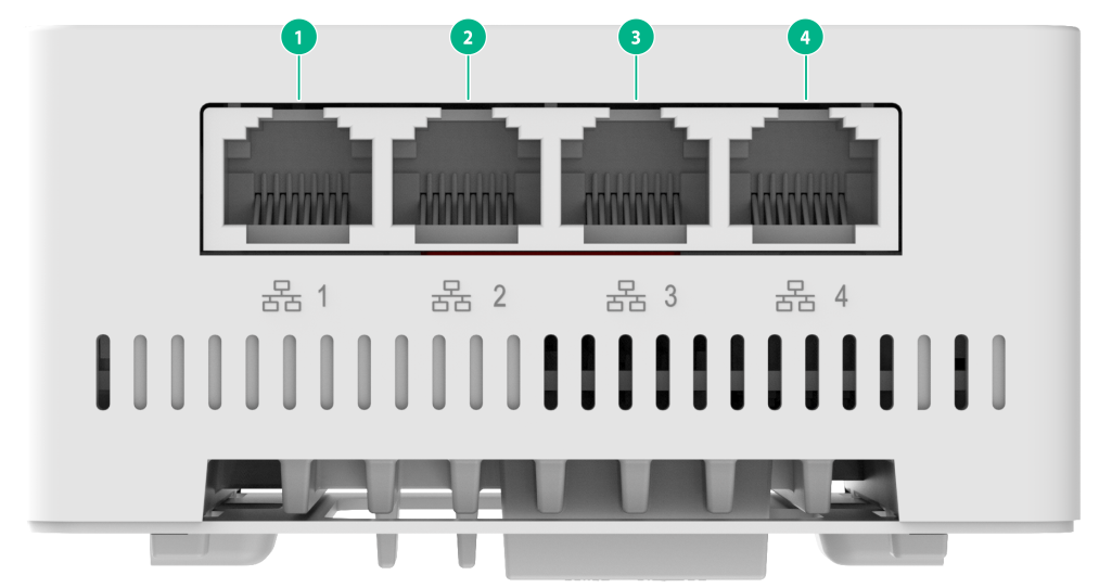
|
(1) 10/100/1000M Ethernet copper ports |
|
(1) Console port |
(2) USB port |
(3) Reset button (RST) |
|
(1) Uplink/PoE port |
Table5-1 Technical specifications
|
Item |
Description |
|
Console port |
Used by technical personnel only for device configuration and management. |
|
10/100/1000M Ethernet copper port |
Represented by interface number GE1/0/1to GE1/0/4 in the MAP file and GigabitEthernet 1 to GigabitEthernet 4 on the AC. |
|
Uplink/PoE port (100/1000/2500M Ethernet copper port) |
Used for connecting the AP to an uplink device for Internet or MAN access. It can also receive PoE power from the uplink device. It is represented by interface number SGE1/0/1 in the MAP file and smartrate-ethernet 1 on the AC. |
|
USB port |
Used for data reading or writing. |
|
Reset button |
For more information, see Table5-5. |
|
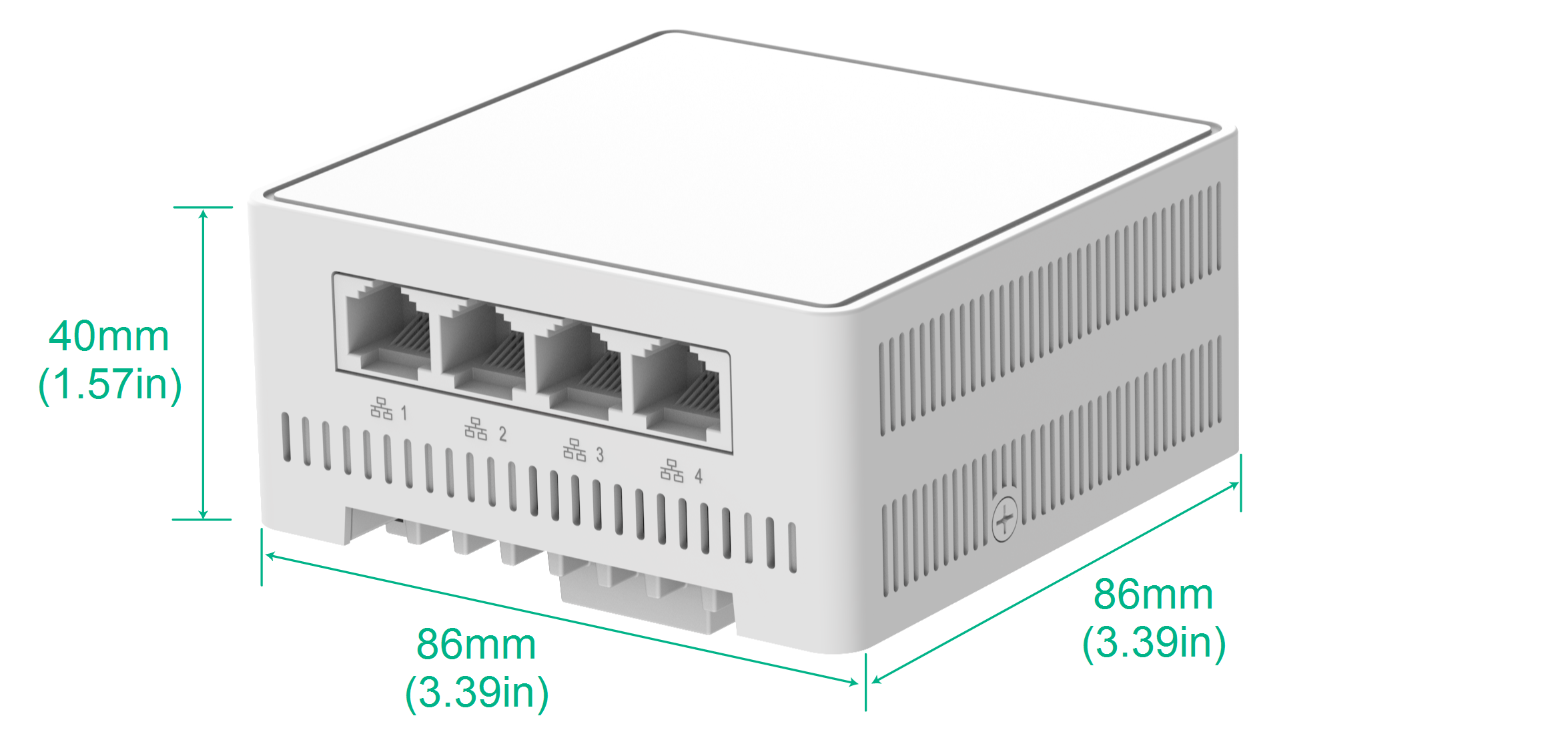
Dimensions (H × W × D) |
40 × 86 × 86 mm (1.57 × 3.39 × 3.39 in, excluding the mounting bracket) |
|
Weight |
259 g (0.57 lb) |
|
Power consumption |
15.12 W |
|
Power supply |
PoE power supply |
|
Antenna |
Built-in antenna: · 2.4 G: 4 dBi gain · 5 G: 5 dBi gain |
|
Standards |
· IEEE802.11a/b/g/n/ac/ax/be · IEEE802.3at/bt |
LEDs
The LED status varies by AP operating mode. For information about the supported operating modes, see the release notes for the AP.
LED descriptions (fit mode)
Table5-2 LED descriptions (fit mode)
|
LED status |
Description |
||
|
Off |
No power is present or the LED has been turned off. |
||
|
Yellow |
Steady on |
The AP is initializing, or an initialization exception has occurred. |
|
|
Flashing (twice per second) |
The Ethernet interfaces are down and no mesh links are established. |
||
|
Green |
Steady on |
The AP has registered to an AC, but does not have any associated clients. |
|
|
Flashing (once per two seconds) |
The AP has started up but has not registered to any AC. |
||
|
Flashing (twice per second) |
The AP is upgrading the image. |
||
|
Blue |
Flashing (once per second) |
The radios have associated clients. |
|
LED descriptions (cloud mode)
Table5-3 LED descriptions (cloud mode)
|
LED status |
Description |
||
|
Off |
No power is present or the LED has been turned off. |
||
|
Yellow |
Steady on |
The AP is initializing, or an initialization exception has occurred. |
|
|
Flashing (twice per second) |
The Ethernet interfaces are down and no mesh links are established. |
||
|
Green |
Steady on |
The AP is in standby state and has connected to the Cloudnet platform, but does not have any associated clients. |
|
|
Flashing (once per second) |
The AP has connected to the Cloudnet platform and has associated clients. |
||
|
Flashing (twice per second) |
The AP is upgrading the image. |
||
|
Blue |
Steady on |
The AP is in standby state, but has not connected to the Cloudnet platform and does not have associated clients. |
|
|
Flashing (once per second) |
The AP has not connected to the Cloudnet platform, but has associated clients. |
||
LED descriptions (anchor AC mode)
Table5-4 LED descriptions (anchor AC mode)
|
LED status |
Description |
||
|
Off |
No power is present or the LED has been turned off. |
||
|
Yellow |
Steady on |
The AP is initializing, or an initialization exception has occurred. |
|
|
Flashing (twice per second) |
The Ethernet interfaces are down and no mesh links are established. |
||
|
Green |
Steady on |
The AP has started up and is in standby state, but does not have any associated clients. |
|
|
Flashing (twice per second) |
The AP is upgrading the image. |
||
|
Blue |
Flashing (once per second) |
The AP has associated clients. |
|
RESET button descriptions
Table5-5 RESET button descriptions
|
Press and hold duration (sec) |
Button LED status |
Description |
|
|
0 to 5 |
Steady green |
Reset the AP. |
|
|
5 to 20 |
Flashing green (twice per second) |
Restore to the factory defaults. |
|
|
20 to 30 |
Yellow |
Flashing (once per two seconds) |
The AP is operating in fit AP mode. NOTE: The system will change the operating mode to cloud if you press and hold the button until the LED flashes green four times per second. |
|
Flashing (twice per second) |
The AP is operating in anchor AC mode. |
||
|
Flashing (four times per second) |
The AP is operating in cloud mode. |
||
|
> 30 |
Yellow |
Flashing (twice per second) |
The AP is operating in anchor AC mode. |
|
Flashing (four times per second) |
The AP is operating in cloud mode. |
||
|
Green |
Flashing (four times per second) |
Change the AP operating mode to cloud. NOTE: If you release the button, the AP will restart for the new mode to take effect. |
|
