- Table of Contents
- Related Documents
-
| Title | Size | Download |
|---|---|---|
| 02-Removable Components | 5.91 MB |
2 Removable components
MSUs
MSU-100
View
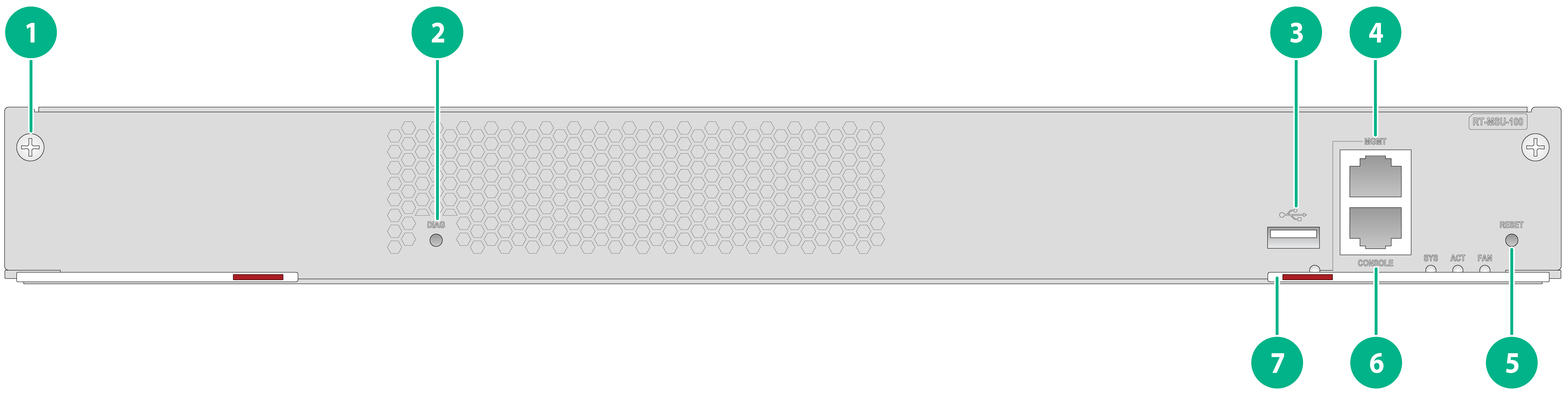
Figure2-1 MSU-100 view
|
(1) Captive screw |
(2) DIAG button |
|
(3) USB port |
(4) Management Ethernet port |
|
(5) Reset button (RESET) |
(6) Console port |
|
(7) Ejector lever |
|
LEDs
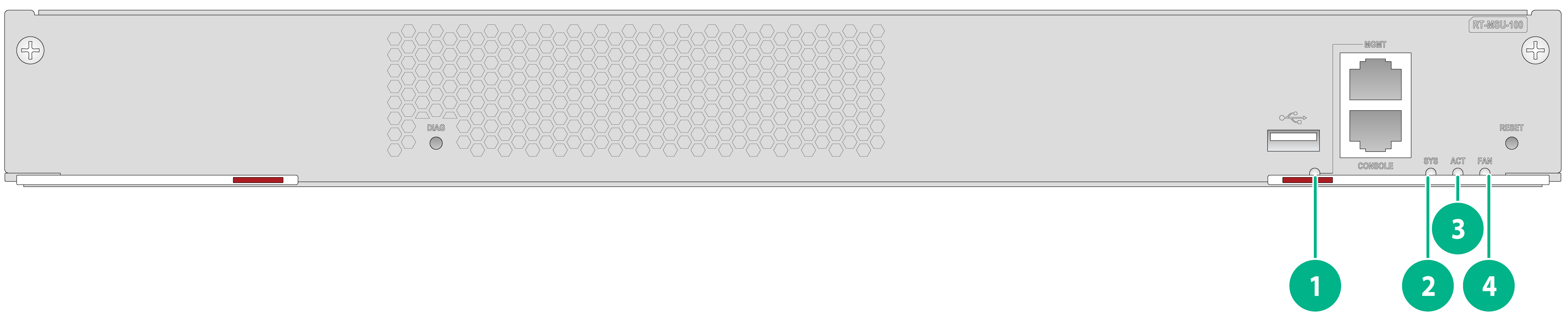
Figure2-2 MSU-100 LEDs
|
(1) Management Ethernet copper port LED |
(1) System status LED (SYS) |
|
(3) MSU active/standby status LED (ACT) |
(4) Fan tray status LED (FAN) |
Table2-1 LED description
|
LED |
Status |
Description |
|
System LED (SYS) |
Flashing green (eight times per second) |
The device is in BootWare stage. |
|
Steady green |
The device is in Kernel stage, including Eshell stage. |
|
|
Flashing green (once per second) |
The Comware system is starting up or is operating correctly. |
|
|
Flashing yellow (once per second) |
Memory test failed in BootWare stage. |
|
|
Flashing yellow (eight times per second) |
The extended BootWare segment does not exist. |
|
|
Steady yellow |
The boot.bin file does not exist. |
|
|
Off |
No power input, or an exception has occurred. |
|
|
MSU active/standby status LED (ACT) |
Steady green |
The MSU is in active mode. |
|
Off |
The MSU is in standby mode. |
|
|
Fan tray status LED (FAN) |
Steady green |
Both fan trays are operating correctly. |
|
Flashing green (once per second) |
One fan tray is operating correctly and the other one is not present. |
|
|
Steady yellow |
A minimum of one fan try is faulty. |
|
|
Off |
Both fan trays are not present. |
|
|
Management Ethernet copper port LED |
Steady green |
A 1000 Mbps link is present on the port. |
|
Flashing green |
The port is sending or receiving data at 1000 Mbps. |
|
|
Steady yellow |
A 10 or 100 Mbps link is present on the port. |
|
|
Flashing yellow |
The port is sending or receiving data at 10 or 100 Mbps. |
|
|
Off |
No link is present on the port. |
Ports
Table2-2 Port specifications
|
Port type |
Specification |
|
Console port |
1 |
|
GE management port |
1 |
|
USB port |
1 |
|
DIAG button |
1 |
Technical specifications
Table2-3 Technical specifications
|
Item |
Specification |
|
Net weight |
1.54 kg (3.40 lb) |
|
Dimensions (H × W × D) |
42.6 × 375 × 227 mm (1.68 × 14.76 × 8.94 in) |
|
Max power consumption |
24.60 W |
|
Memory |
4 GB DDR4 |
|
Flash |
4 GB |
MSU-200
View
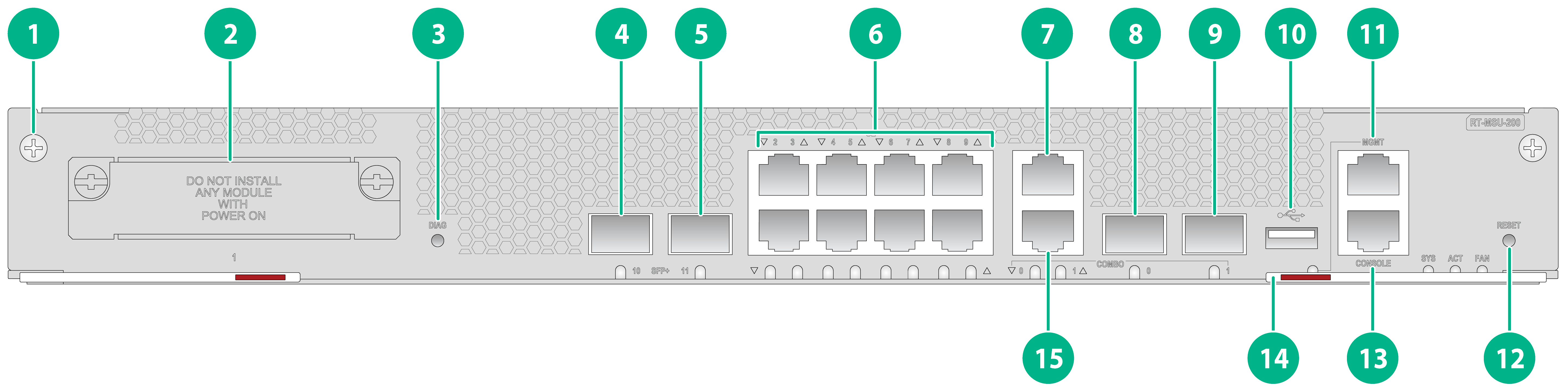
Figure2-3 MSU-200 view
|
(1) Captive screw |
(2) SIC slot |
|
(3) DIAG button |
(4) SFP+ port SFP+10 |
|
(5) SFP+ port SFP+11 |
(6) GE copper ports GE2 to GE9 |
|
(7) GE copper port GE1 |
(8) GE fiber port SFP0 |
|
(9) GE fiber port SFP1 |
(10) USB port |
|
(11) Management Ethernet port |
(12) Reset button (RESET) |
|
(13) Console port |
(14) Ejector lever |
|
(15) GE copper port GE0 |
|
LEDs
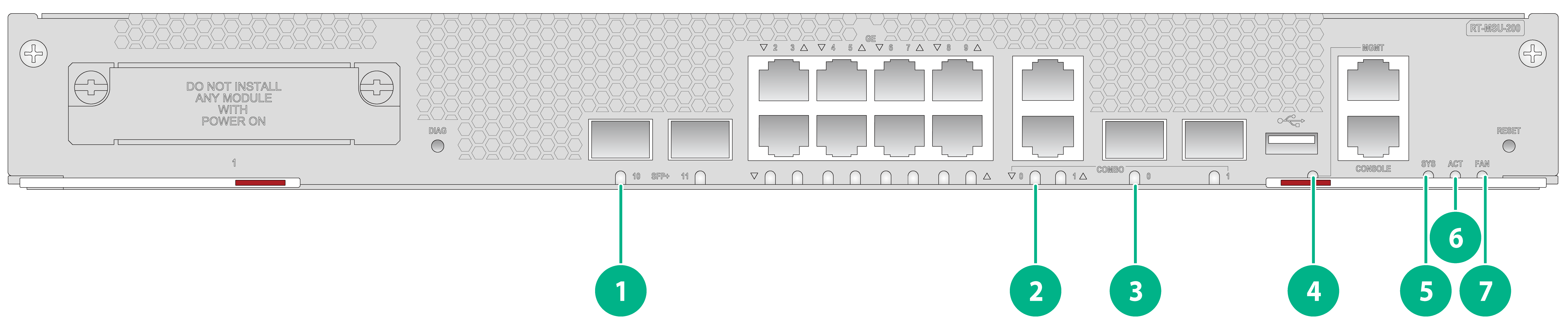
Figure2-4 MSU-200 LEDs
|
(1) SFP+ fiber port LED |
(2) GE port LED |
|
(3) SFP fiber port LED |
(4) Management Ethernet copper port LED |
|
(5) System status LED (SYS) |
(6) MSU active/standby status LED (ACT) |
|
(7) Fan tray status LED (FAN) |
|
Table2-4 LED description
|
LED |
Status |
Description |
|
System LED (SYS) |
Flashing green (eight times per second) |
The device is in BootWare stage. |
|
Steady green |
The device is in Kernel stage, including Eshell stage. |
|
|
Flashing green (once per second) |
The Comware system is starting up or is operating correctly. |
|
|
Flashing yellow (once per second) |
Memory test failed in BootWare stage. |
|
|
Flashing yellow (eight times per second) |
The extended BootWare segment does not exist. |
|
|
Steady yellow |
The boot.bin file does not exist. |
|
|
Off |
No power input, or an exception has occurred. |
|
|
MSU active/standby status LED (ACT) |
Steady green |
The MSU is in active mode. |
|
Off |
The MSU is in standby mode. |
|
|
Fan tray status LED (FAN) |
Steady green |
Both fan trays are operating correctly. |
|
Flashing green (once per second) |
One fan tray is operating correctly and the other one is not present. |
|
|
Steady yellow |
A minimum of one fan try is faulty. |
|
|
Off |
Both fan trays are not present. |
|
|
SFP+ fiber port LED |
Steady green |
A 10 Gbps link is present on the port. |
|
Flashing green |
The port is sending or receiving data at 10 Gbps. |
|
|
Steady yellow |
A 1000 Mbps link is present on the port. |
|
|
Flashing yellow |
The port is sending or receiving data at 1000 Mbps. |
|
|
Off |
No link is present on the port. |
|
|
SFP fiber port LED |
Steady green |
A 1000 Mbps link is present on the port. |
|
Flashing green |
The port is sending or receiving data at 1000 Mbps. |
|
|
Steady yellow |
A 100 Mbps link is present on the port. |
|
|
Flashing yellow |
The port is sending or receiving data at 100 Mbps. |
|
|
Off |
No link is present on the port. |
|
|
GE port LED/Management Ethernet copper port LED |
Steady green |
A 1000 Mbps link is present on the port. |
|
Flashing green |
The port is sending or receiving data at 1000 Mbps. |
|
|
Steady yellow |
A 10 or 100 Mbps link is present on the port. |
|
|
Flashing yellow |
The port is sending or receiving data at 10 or 100 Mbps. |
|
|
Off |
No link is present on the port. |
Ports
Table2-5 Port specifications
|
Port type |
Specification |
|
Console port |
1 |
|
GE management port |
1 |
|
GE copper port |
8 |
|
Combo interface |
2 (SFP0/GE0, SFP1/GE1) |
|
SFP+ fiber port |
2 |
|
USB port |
1 |
|
DIAG button |
1 |
|
SIC slot |
1 |
Technical specifications
Table2-6 Technical specifications
|
Item |
Specification |
|
Net weight |
1.72 kg (3.79 lb) |
|
Dimensions (H × W × D) |
42.6 × 375 × 227 mm (1.68 × 14.76 × 8.94 in) |
|
Max power consumption |
45.00 W |
|
Memory |
4 GB DDR4 |
|
Flash |
4 GB |
MSU-400-G
View
Figure2-5 MSU-400-G view
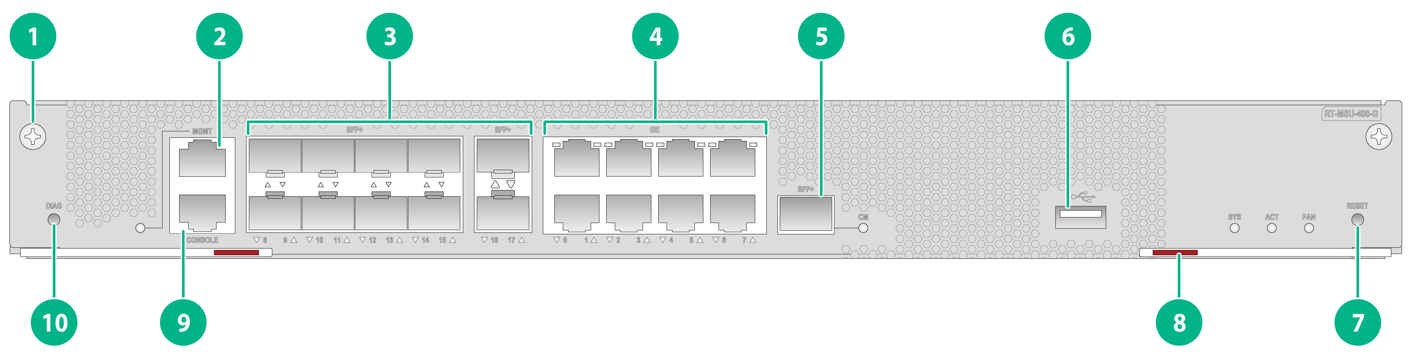
|
(1) Captive screw |
(2) Management Ethernet port |
|
(3) SFP+ ports SFP+8 to SFP+17 |
(4) GE copper ports GE0 to GE7 |
|
(5) Cloud cluster management SFP+ fiber port |
(6) USB port |
|
(7) Reset button (RESET) |
(8) Ejector lever |
|
(9) Console port |
(10) DIAG button |
LEDs
Figure2-6 MSU-400-G LEDs
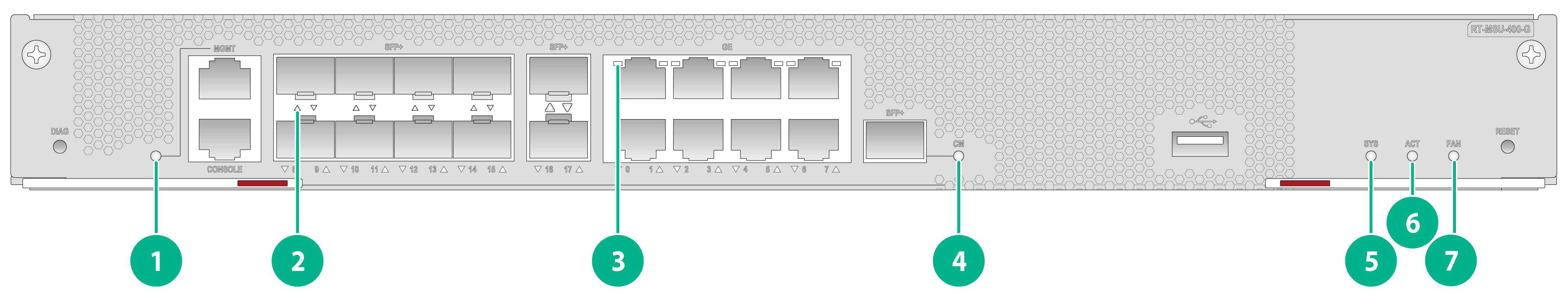
|
(1) Management Ethernet copper port LED |
(2) SFP+ fiber port LED |
|
(3) GE port LED |
(4) Cloud cluster management SFP+ fiber port LED |
|
(5) System status LED (SYS) |
(6) MSU active/standby status LED (ACT) |
|
(7) Fan tray status LED (FAN) |
|
Table2-7 LED description
|
LED |
Status |
Description |
|
System LED (SYS) |
Flashing green (eight times per second) |
The device is in BootWare stage. |
|
Steady green |
The device is in Kernel stage, including Eshell stage. |
|
|
Flashing green (once per second) |
The Comware system is starting up or is operating correctly. |
|
|
Flashing yellow (once per second) |
Memory test failed in BootWare stage. |
|
|
Flashing yellow (eight times per second) |
The extended BootWare segment does not exist. |
|
|
Steady yellow |
The boot.bin file does not exist. |
|
|
Off |
No power input, or an exception has occurred. |
|
|
MSU active/standby status LED (ACT) |
Steady green |
The MSU is in active mode. |
|
Flashing green (eight times per second) |
Bulk backup in progress. |
|
|
Off |
The MSU is in standby mode. |
|
|
Fan tray status LED (FAN) |
Steady green |
Both fan trays are operating correctly. |
|
Flashing green (once per second) |
One fan tray is operating correctly and the other one is not present. |
|
|
Steady yellow |
A minimum of one fan try is faulty. |
|
|
Off |
Both fan trays are not present. |
|
|
Cloud cluster management SFP+ fiber port LED SFP+ fiber port LED |
Steady green |
A 10 Gbps link is present on the port. |
|
Flashing green |
The port is sending or receiving data at 10 Gbps. |
|
|
Steady yellow |
A 1000 Mbps link is present on the port. |
|
|
Flashing yellow |
The port is sending or receiving data at 1000 Mbps. |
|
|
Off |
No link is present on the port. |
|
|
GE port LED/Management Ethernet copper port LED |
Steady green |
A 1000 Mbps link is present on the port. |
|
Flashing green |
The port is sending or receiving data at 1000 Mbps. |
|
|
Steady yellow |
A 10 or 100 Mbps link is present on the port. |
|
|
Flashing yellow |
The port is sending or receiving data at 10 or 100 Mbps. |
|
|
Off |
No link is present on the port. |
Ports
Table2-8 Port specifications
|
Port type |
Specification |
|
Console port |
1 |
|
GE management port |
1 |
|
GE copper port |
8 |
|
SFP+ fiber port |
11 (including one cloud cluster management port) |
|
USB port |
1 |
|
DIAG button |
1 |
Technical specifications
Table2-9 Technical specifications
|
Item |
Specification |
|
Net weight |
2.2 kg (4.85 lb) |
|
Dimensions (H × W × D) |
42.6 × 375 × 227 mm (1.68 × 14.76 × 8.94 in) |
|
Max power consumption |
121.30 W |
|
Memory |
8 GB DDR4 |
|
Flash |
4 GB |
Interface modules
Weights, dimensions, and power consumptions
Table2-1 Weights, dimensions, and power consumptions
|
Module model |
Net weight |
Max power consumption |
Dimensions (H × W × D) |
|
RT-SIC-5G |
0.19 kg (0.42 lb) |
7.60 W |
19.8 × 80 × 138 mm (0.78 × 3.15 × 5.43 in) |
|
RT-XMIM-8GEE-R |
0.64 kg (1.41 lb) |
8.80 W |
19.8 × 186 × 228 mm (0.78 × 7.32 × 8.98 in) |
|
RT-XMIM-8GEF-R |
0.65 kg (1.43 lb) |
17.16 W |
19.8 × 186 × 228 mm (0.78 × 7.32 × 8.98 in) |
|
RT-XMIM-4XP |
0.7 kg (1.54 lb) |
25 W |
19.8 × 186 × 228 mm (0.78 × 7.32 × 8.98 in) |
|
RT-XMIM-1POS |
0.62 kg (1.37 lb) |
9.70 W |
19.8 × 186 × 228 mm (0.78 × 7.32 × 8.98 in) |
|
RT-XMIM-2POS |
0.64 kg (1.41 lb) |
10.30 W |
19.8 × 186 × 228 mm (0.78 × 7.32 × 8.98 in) |
|
RT-XMIM-1CPOS |
0.64 kg (1.41 lb) |
11 W |
19.8 × 186 × 228 mm (0.78 × 7.32 × 8.98 in) |
|
RT-XMIM-2E1 |
0.6 kg (1.32 lb) |
5.00 W |
19.8 × 186 × 228 mm (0.78 × 7.32 × 8.98 in) |
|
RT-XMIM-4E1 |
0.62 kg (1.37 lb) |
5.40 W |
19.8 × 186 × 228 mm (0.78 × 7.32 × 8.98 in) |
|
RT-XMIM-8E1 |
0.64 kg (1.41 lb) |
6.10 W |
19.8 × 186 × 228 mm (0.78 × 7.32 × 8.98 in) |
|
RT-XMIM-CNDE-SJK |
0.6 kg (1.32 lb) |
13 W |
19.8 × 186 × 228 mm (0.78 × 7.32 × 8.98 in) |
Interface modules
The device supports SIC and XMIM interface modules. For more information about the views, LEDs, and specifications of the interface modules, see H3C MSR Router Series Interface Module Guide.
Power supplies
The device supports AC power supplies, DC power supplies, and mix of AC and DC power supplies. The power supplies can be hot swapped and configured in redundancy. In AC or DC power supply mode, you can install only one power supply, or two or three power supplies for 1+1 or 1+2 power supply redundancy respectively. In mixed power supply mode, you can install two power supplies, or three power supplies for 2+1 power supply redundancy.
The device supports only mix of 450 W AC and DC power supplies.
PSR250-12A
View
Figure2-7 PSR250-12A power supply view
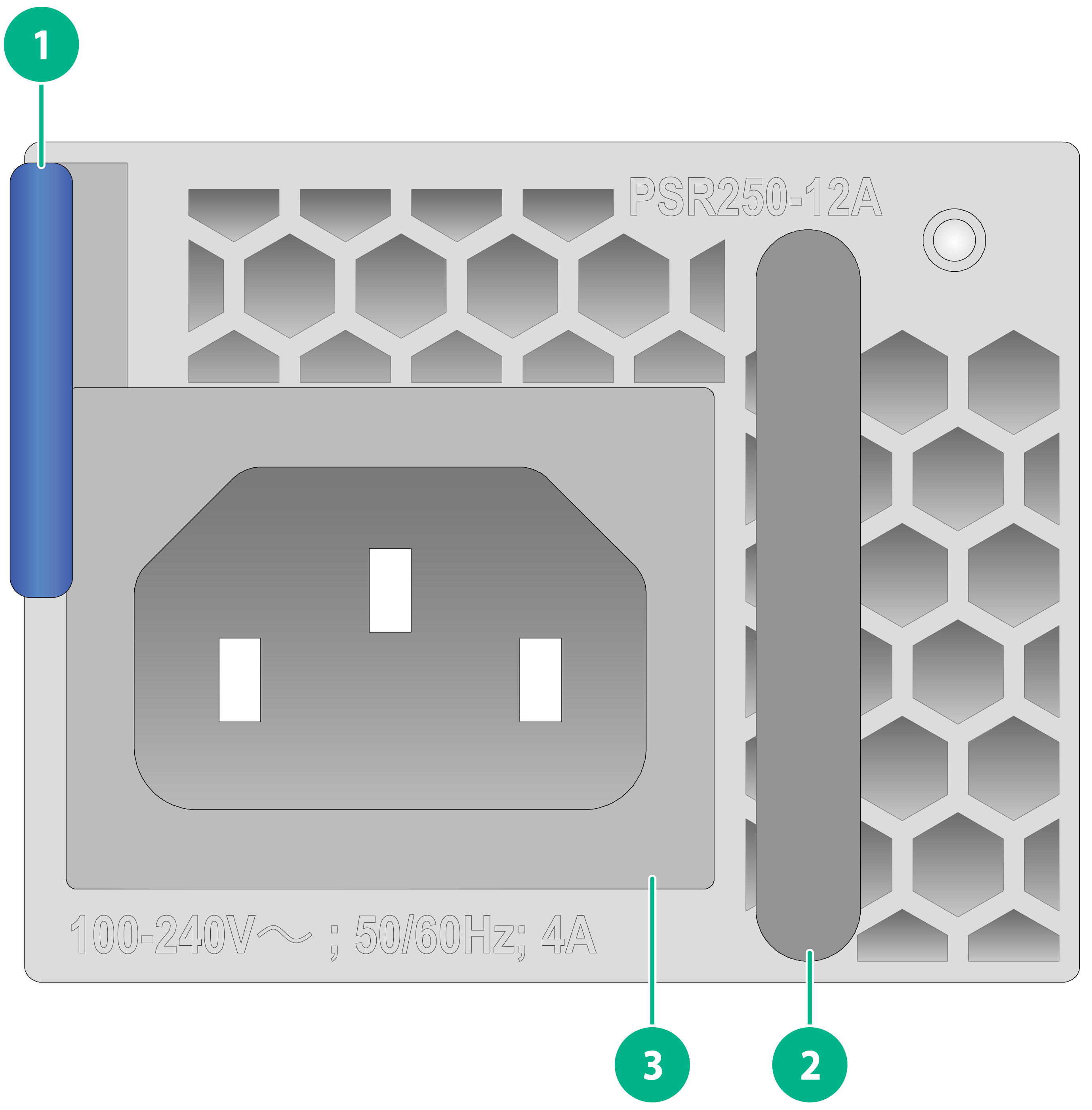
|
(1) Latch |
(2) Handle |
|
(3) Power receptacle |
|
LEDs
Figure2-8 PSR250-12A AC power supply LEDs
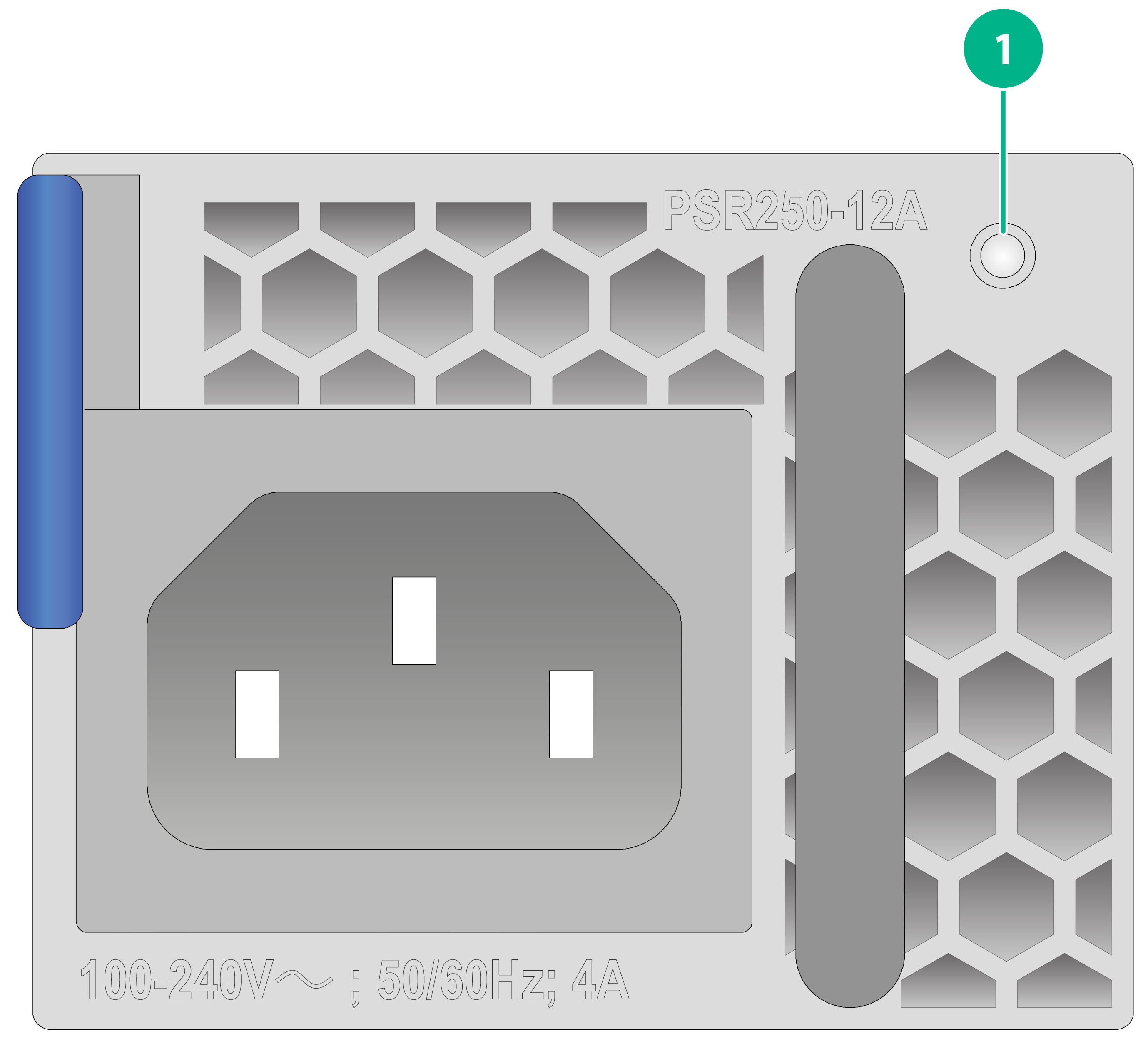
|
(1) Status LED |
Table2-2 LED description
|
LED |
Status |
Description |
|
Status LED |
Steady green |
The power supply is operating correctly. |
|
Flashing green |
The power supply has normal power input but has not been turned on. |
|
|
Steady red |
The power supply is faulty. |
|
|
Flashing red/green |
An alarm is present on the power supply. |
|
|
Flashing red |
This power supply does not have power input but the other power supply has power input. |
|
|
Off |
No power is present. |
Technical specifications
Table2-3 Technical specifications
|
Item |
Specification |
|
Net weight |
0.64 kg (1.41 lb) |
|
Dimensions (H × W × D) |
40 × 51 × 221 mm (1.57 × 2.01 × 8.70 in) |
|
Rated input voltage |
100 to 240 VAC @ 50 or 60 Hz |
|
Max input current |
4 A |
|
Max power |
250 W |
PSR450-12A
View
Figure2-9 PSR450-12A power supply view

|
(1) Latch |
(2) Handle |
|
(3) Power receptacle |
|
LEDs
Figure2-10 PSR450-12A AC power supply LEDs

|
(1) Status LED |
Table2-4 LED description
|
LED |
Status |
Description |
|
Status LED |
Steady green |
The power supply is operating correctly. |
|
Flashing green |
The power supply has normal power input but has not been turned on. |
|
|
Steady red |
The power supply is faulty. |
|
|
Flashing red/green |
An alarm is present on the power supply. |
|
|
Flashing red |
This power supply does not have power input but the other power supply has power input. |
|
|
Off |
No power is present. |
Technical specifications
Table2-5 Technical specifications
|
Item |
Specification |
|
Net weight |
0.65 kg (1.43 lb) |
|
Dimensions (H × W × D) |
40 × 51 × 221 mm (1.57 × 2.01 × 8.70 in) |
|
Rated input voltage |
100 to 240 VAC @ 50 or 60 Hz |
|
Max input current |
6 A |
|
Max power |
450 W |
PSR450-12D-F
View
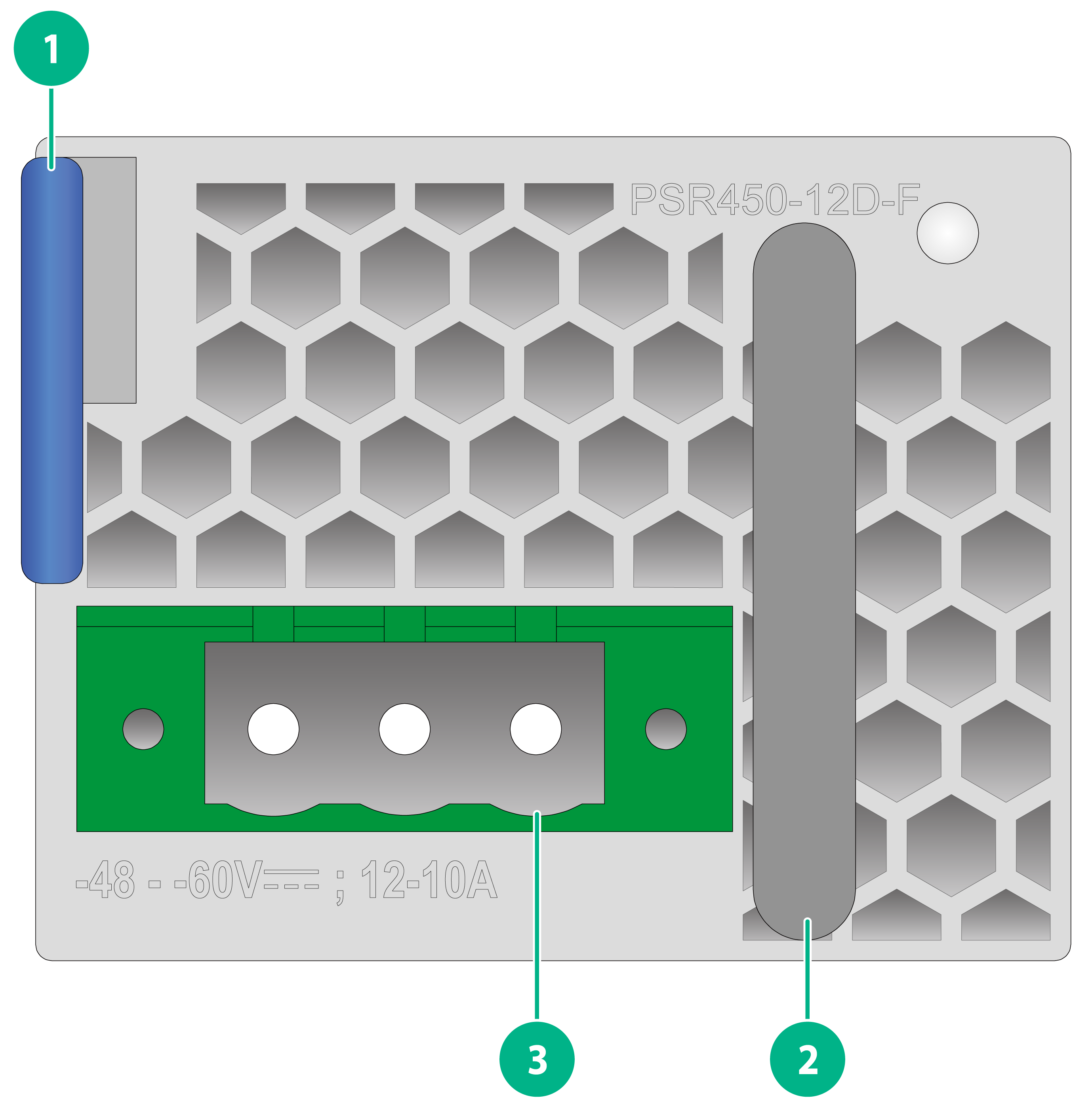
Figure2-11 PSR450-12D-F power supply view
|
(1) Latch |
(2) Handle |
|
(3) Power receptacle |
|
LEDs
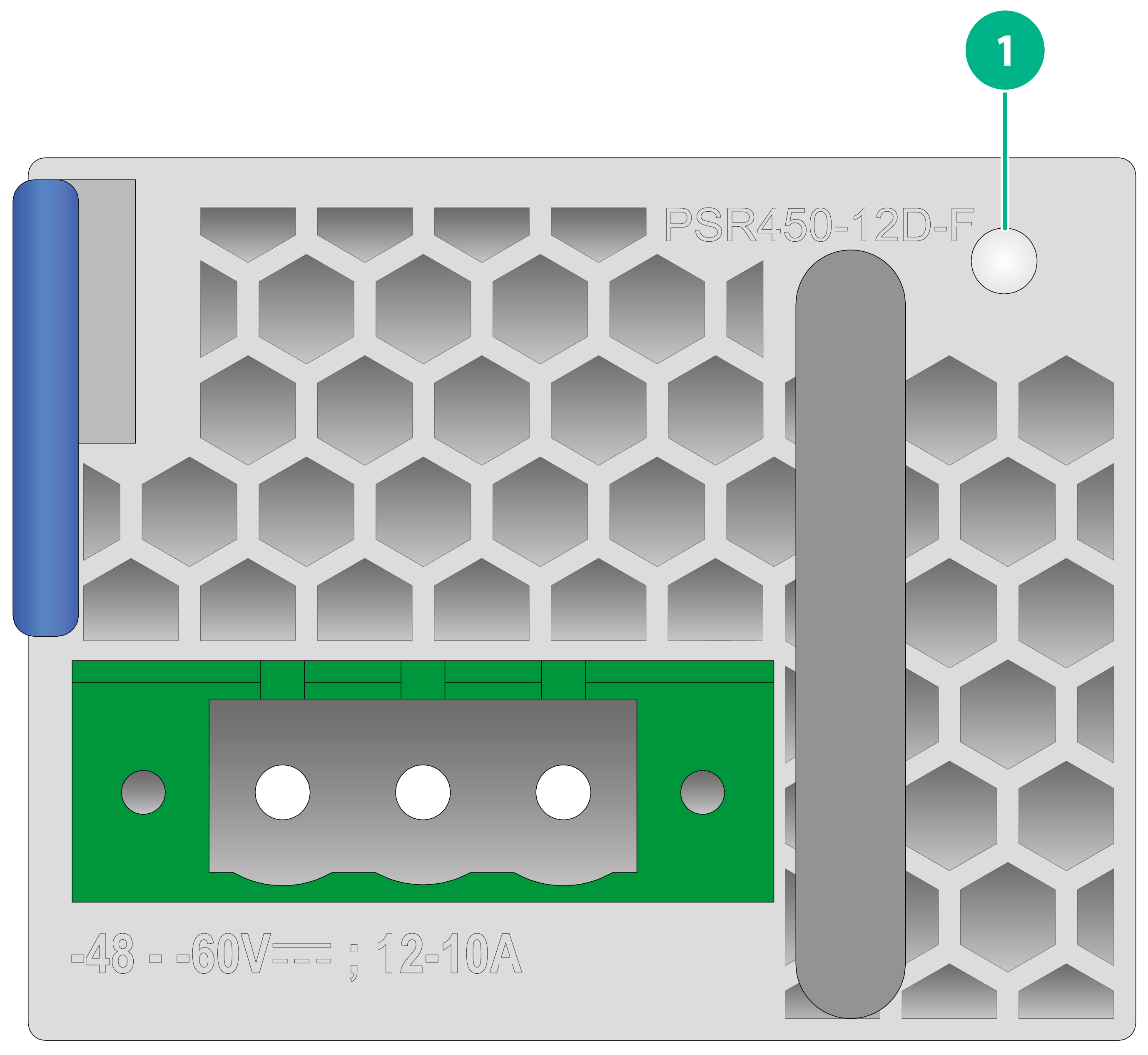
Figure2-12 PSR450-12D-F DC power supply LEDs
|
(1) Status LED |
Table2-6 LED description
|
LED |
Status |
Description |
|
Status LED |
Steady green |
The power supply is operating correctly. |
|
Flashing green |
The power supply has normal power input but has not been turned on. |
|
|
Steady red |
The power supply is faulty. |
|
|
Flashing red/green |
An alarm is present on the power supply. |
|
|
Flashing red |
This power supply does not have power input but the other power supply has power input. |
|
|
Off |
No power is present. |
Technical specifications
Table2-7 Technical specifications
|
Item |
Specification |
|
Net weight |
0.68 kg (1.50 lb) |
|
Dimensions (H × W × D) |
40 × 51 × 221 mm (1.57 × 2.01 × 8.70 in) |
|
Rated input voltage |
–48 to –60 VDC |
|
Max input current |
12 to 10 A |
|
Max power |
450 W |
Fan trays
FAN-80B-2-C
View
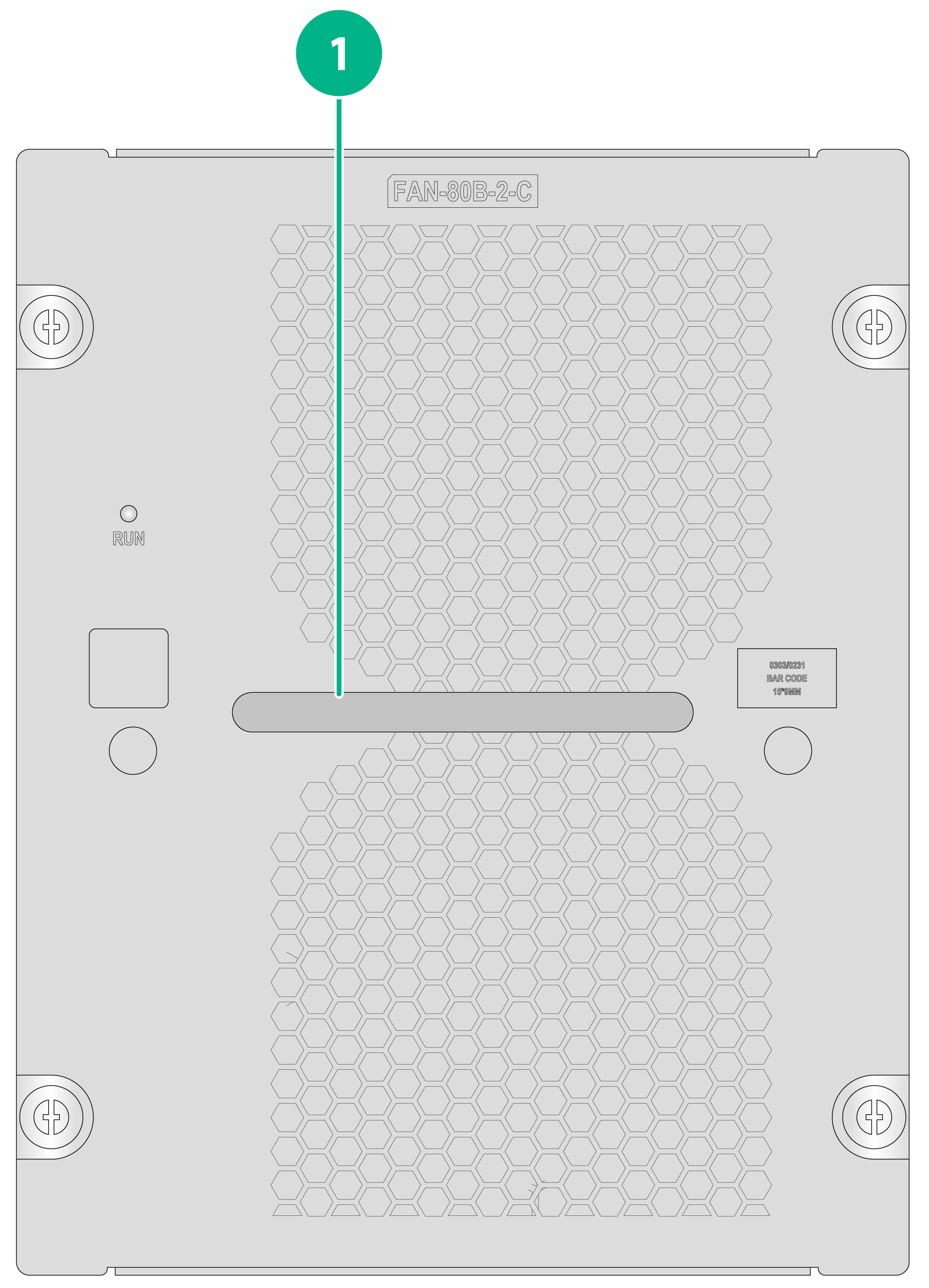
Figure2-13 FAN-80B-2-C fan tray view
|
(1) Handle |
LEDs
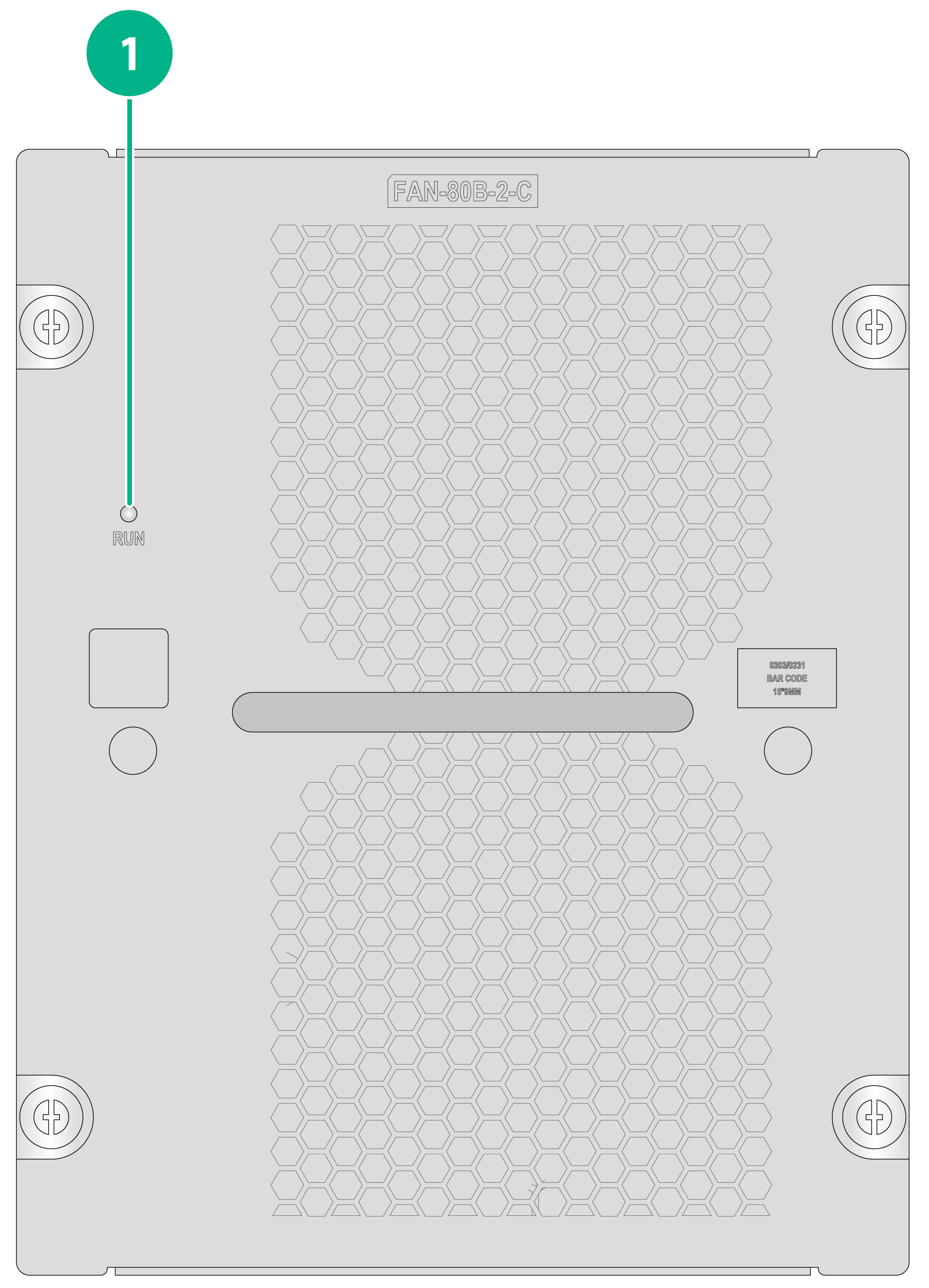
Figure2-14 FAN-80B-2-C fan tray LEDs
|
(1) Status LED |
Table2-8 LED description
|
LED |
LED status |
Description |
|
RUN |
Steady green |
The fan tray is operating correctly. |
|
Steady yellow |
The fan tray is faulty. |
|
|
Off |
No fan tray is present or no power is present on the fan tray. |
Technical specifications
Table2-9 Technical specifications
|
Item |
Specification |
|
Net weight |
1.06 kg (2.34 lb) |
|
Dimensions (H × W × D) |
171 × 136 × 93 mm (6.73 × 5.35 × 3.66 in) |
|
Max power consumption |
90 W |
|
Maximum rotating speed |
13800 RPM |
|
Maximum air flow rate |
135.15 CFM (3.83 m3/min) |
|
Number of fans |
2 |
|
Automatic speed adjustment |
Supported |
|
Anti-misinsertion |
Supported |
|
Hot swapping |
Supported |
