- Table of Contents
- Related Documents
-
| Title | Size | Download |
|---|---|---|
| 01-About the Router | 1.34 MB |
1 About the router
"MSU" in this document refers to the main-control and service-processing unit.
Chassis views
The figures in this section are for illustration only.
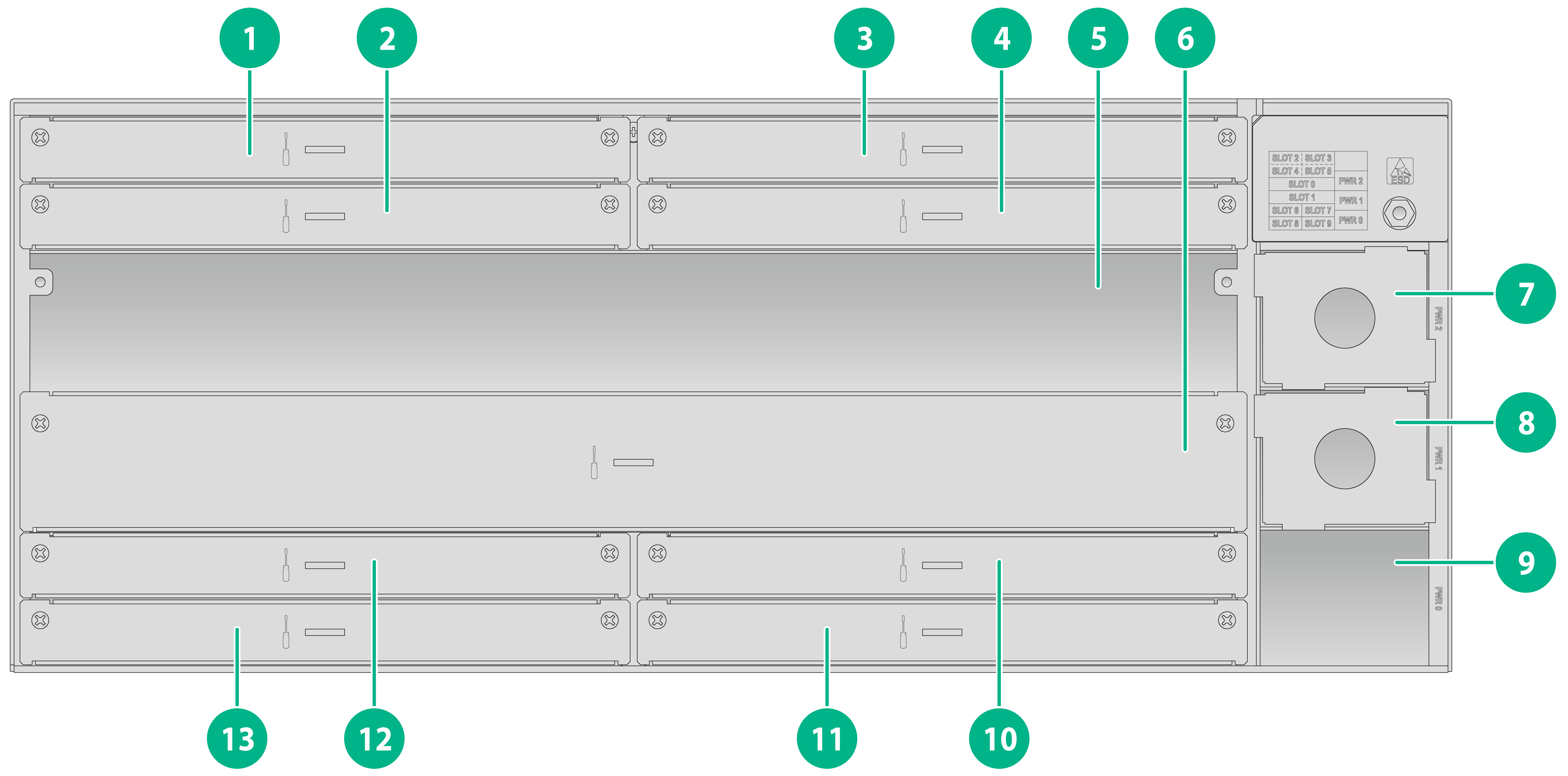
Figure1-1 MSR5680-X3 front panel
|
(1) XMIM interface module slot 2 |
(2) XMIM interface module slot 4 |
|
(3) XMIM interface module slot 3 |
(4) XMIM interface module slot 5 |
|
(5) MSU slot 0 |
(6) MSU slot 1 |
|
(7) Power supply slot PWR2 |
(8) Power supply slot PWR1 |
|
(9) Power supply slot PWR0 |
(10) XMIM interface module slot 7 |
|
(11) XMIM interface module slot 9 |
(12) XMIM interface module slot 6 |
|
(13) XMIM interface module slot 8 |
|
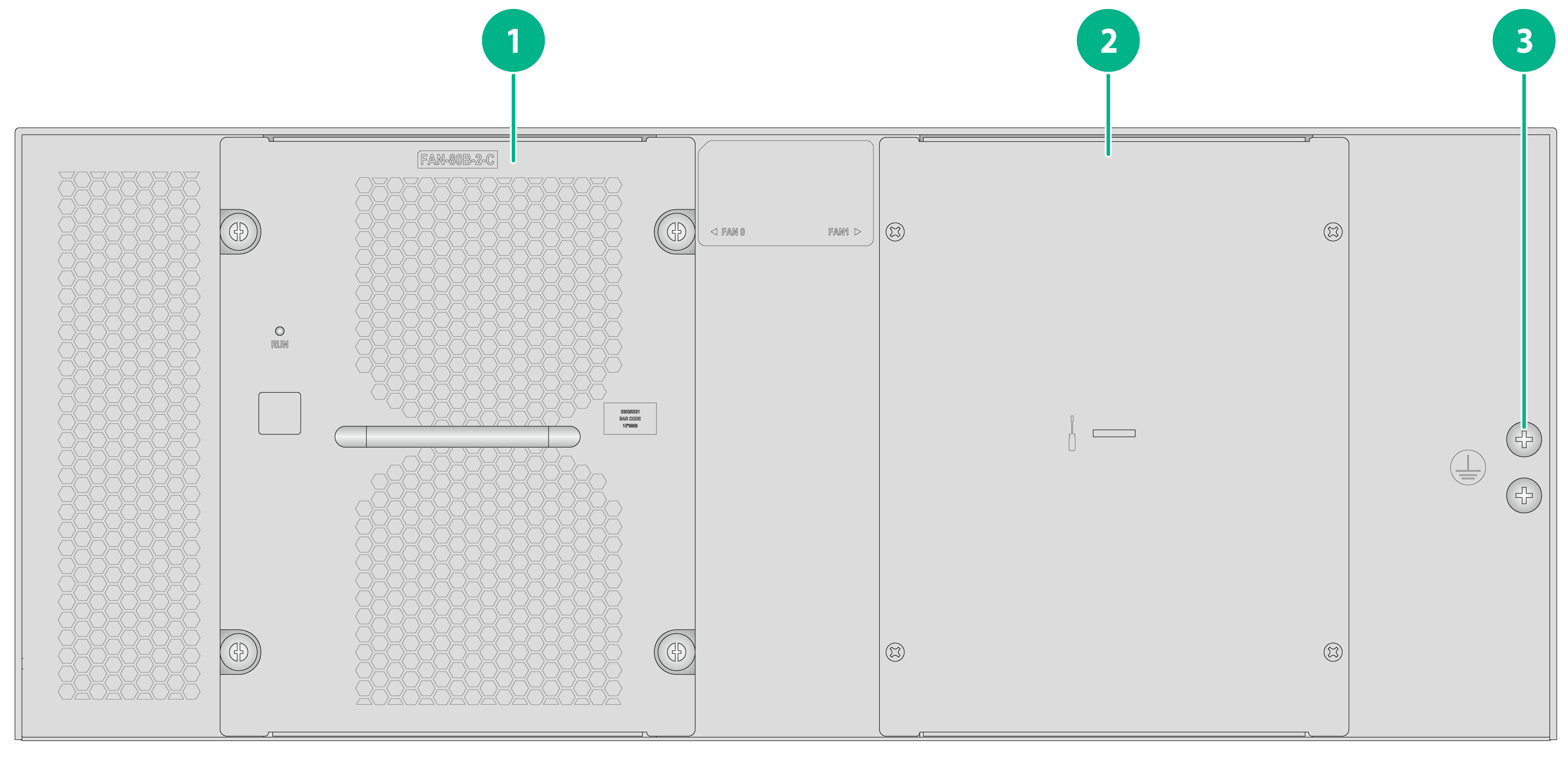
Figure1-2 MSR5680-X3 rear panel
|
(1) Fan tray slot 0 |
(2) Fan tray slot 1 |
|
(3) Grounding screw |
|
Slot arrangement and interface numbering
Slot arrangement
Table1-1 Slot arrangement on the device
|
Model |
Slot arrangement |
|
MSR5680-X3 |
|
|
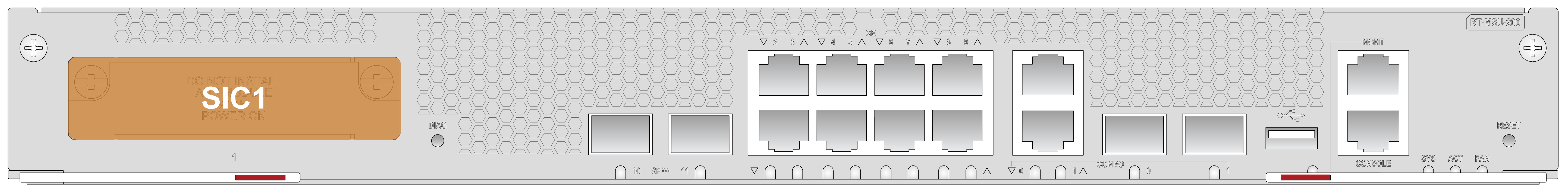
MSU-200 |
|
|
|
|

Interface numbering
Conventions
The interfaces (except the management Ethernet interface) on the device are numbered in the interface-type X/Y/Z format. The management Ethernet interface number is M-GigabitEthernet 0/0/0.
· interface-type—Type of the interface such as GigabitEthernet and Ten-GigabitEthernet.
· X—Slot number, as shown in Table1-1.
¡ For an MSU or XMIM interface module, X represents the number of the slot where the module resides on the device.
¡ For an SIC interface module, X represents the number of the slot where the MSU resides on the device.
· Y—Subslot number.
¡ For an MSU or XMIM interface module, the number is fixed at 0.
¡ For an SIC interface module, the number is fixed at 1.
· Z—Interface number.
¡ For an MSU or XMIM interface module, Z represents the number of the interface on the module.
¡ For a SIC-5G interface module, the number for the SIM1 slot is 0, and the number for the SIM2 slot is 1.
Examples
An XMIM-8GEE-R interface module is installed in slot 6 of the device. Fixed GE copper ports on the interface module are numbered GigabitEthernet 6/0/0 through GigabitEthernet 6/0/7, respectively.
An MSU-200 is installed in slot 0 of the device and a SIC-5G interface module is installed on the MSU. Fixed SFP+ fiber ports on MSU-200 are numbered Ten-GigabitEthernet 0/0/10 and Ten-GigabitEthernet 0/0/11, respectively. Ports on the SIC-5G interface module are numbered Cellular 0/1/0 and Cellular 0/1/1, respectively.
Technical specifications
Table1-2 MSR5680-X3 technical specifications
|
Item |
Specification |
|
Dimensions (H × W × D) (excluding rubber feet and mounting brackets) |
175 × 440 × 330 mm (6.89 × 17.32 × 12.99 in) |
|
Chassis weight (including mounting brackets and filler panels) |
10.62 kg (23.41 lb) |
|
Chassis weight (fully configured) |
22.5 kg (49.60 lb) |
|
Device weight |
Weights of the chassis (including mounting brackets and filler panels), modules, power supplies, fan trays, and other removable components |
|
System power consumption |
Total power consumption of all modules and fan trays |
|
Heat dissipation |
Heat dissipation of the router per hour is 0.9 × (total power consumption of all modules and fan trays)/0.9 × 3.4121 |
|
MSU slots |
2 |
|
XMIM interface module slots |
8 |
|
Fan tray slots |
2 |
|
Power supply slots |
3 |
|
Operating temperature |
0°C to 45°C (32°F to 113°F) |
|
Operating humidity |
5% RH to 95% RH, noncondensing |
|
|
NOTE: Heat dissipation is measured in BTU/h. 1 W equals 3.4121 BTU/h. |
