- Table of Contents
-
- 17-User Access and Authentication Configuration Guide
- 00-Preface
- 01-AAA configuration
- 02-802.1X configuration
- 03-MAC authentication configuration
- 04-Portal configuration
- 05-Port security configuration
- 06-PPPoE configuration
- 07-L2TP configuration
- 08-User profile configuration
- 09-Password control configuration
- Related Documents
-
| Title | Size | Download |
|---|---|---|
| 06-PPPoE configuration | 302.22 KB |
Contents
Restrictions and guidelines for PPPoE
PPPoE server tasks at a glance
Enabling the function of querying and configuring VA interfaces through MIB nodes
Setting the maximum number of PPPoE sessions
Limiting the PPPoE access rate
Configuring the NAS-Port-ID attribute
PPPoE client tasks at a glance
Configuring a dialer interface
Verifying and maintaining PPPoE server
Displaying PPPoE session and user information
Displaying and clearing PPPoE statistics
Displaying VA pool information
Verifying and maintaining PPPoE client
Displaying summary information for a PPPoE session
Displaying and clearing the protocol packet statistics for a PPPoE session
Example: Configuring the PPPoE server to assign IPv4 addresses through a PPP address pool
Example: Configuring the PPPoE server to assign IPv4 addresses through the local DHCP server
Example: Configuring the PPPoE server to assign IPv4 addresses through a remote DHCP server
Example: Configuring the PPPoE server to assign IPv6 addresses through ND and IPv6CP negotiation
Example: Configuring the PPPoE server to assign IPv6 addresses through DHCPv6
Example: Configuring the PPPoE server to assign IPv6 addresses through prefix delegation by DHCPv6
Example: Configuring PPPoE server to assign address pools and VPNs
Example: Configuring a PPPoE client in permanent mode
Example: Configuring a PPPoE client in on-demand mode
Example: Configuring a PPPoE client in diagnostic mode
Configuring PPPoE
About PPPoE
Point-to-Point Protocol over Ethernet (PPPoE) extends PPP by transporting PPP frames encapsulated in Ethernet over point-to-point links.
PPPoE specifies the methods for establishing PPPoE sessions and encapsulating PPP frames over Ethernet. PPPoE requires a point-to-point relationship between peers instead of a point-to-multipoint relationship as in multi-access environments such as Ethernet. PPPoE provides Internet access for the hosts in an Ethernet through a remote access device and implement access control, authentication, and accounting on a per-host basis. Integrating the low cost of Ethernet and scalability and management functions of PPP, PPPoE gained popularity in various application environments, such as residential access networks.
For more information about PPPoE, see RFC 2516.
PPPoE network structure
PPPoE uses the client/server model. The PPPoE client initiates a connection request to the PPPoE server. After session negotiation between them is complete, a session is established between them, and the PPPoE server provides access control, authentication, and accounting to the PPPoE client.
PPPoE network structures are classified into router-initiated and host-initiated network structures depending on the starting point of the PPPoE session.
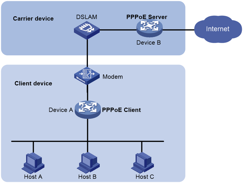
Router-initiated network structure
As shown in Figure 1, the PPPoE session is established between devices (Device A and Device B). All hosts share one PPPoE session for data transmission without being installed with PPPoE client software. This network structure is typically used by enterprises.
Figure 1 Router-initiated network structure
Host-initiated network structure
As shown in Figure 2, a PPPoE session is established between each host (PPPoE client) and the carrier device (PPPoE server). The service provider assigns an account to each host for billing and control. The host must be installed with PPPoE client software.
Figure 2 Host-initiated network structure

Protocols and standards
RFC 2516: A Method for Transmitting PPP Over Ethernet (PPPoE)
Restrictions and guidelines for PPPoE
The PPPoE server supports the following interface views:
· Layer 3 Ethernet interface/subinterface view
· Layer 3 aggregate interface/subinterface view
· VLAN interface view
Configuring the PPPoE server
PPPoE server tasks at a glance
To configure PPPoE server, perform the following tasks:
1. Configuring a PPPoE session
2. (Optional.) Configuring a VA pool
3. (Optional.) Enabling the function of querying and configuring VA interfaces through MIB nodes
4. (Optional.) Setting the maximum number of PPPoE sessions
5. (Optional.) Limiting the PPPoE access rate
6. (Optional.) Configuring the NAS-Port-ID attribute
Configuring a PPPoE session
1. Enter system view.
system-view
2. Create a VT interface and enter VT interface view.
interface virtual-template number
3. Set PPP parameters.
For more information setting PPP parameters, see PPP configuration in Layer 2—WAN Access Configuration Guide.
When configuring PPP authentication, use the PPPoE server as the authenticator.
4. Enable MRU verification for PPPoE applications.
ppp lcp echo mru verify [ minimum value ]
By default, MRU verification is disabled for PPPoE applications.
5. Return to system view.
quit
6. Enter interface view.
interface interface-type interface-number
7. Enable the PPPoE server on the interface and bind this interface to the specified VT interface.
pppoe-server bind virtual-template number
By default, the PPPoE server is disabled on the interface.
8. (Optional.) Configure an access concentrator (AC) name for the PPPoE server.
pppoe-server tag ac-name name
By default, the AC name for the PPPoE server is the device name.
PPPoE clients can choose a PPPoE server according to the AC name. The PPPoE client on H3C devices do not support this feature.
9. (Optional.) Enable the PPPoE server to support the ppp-max-payload tag and specify a range for the PPP maximum payload.
pppoe-server tag ppp-max-payload [ minimum minvalue maximum maxvalue ]
By default, The PPPoE server does not support the ppp-max-payload tag.
10. (Optional.) Set a service name for the PPPoE server
pppoe-server tag service-name name
By default, the PPPoE server does not have a service name.
11. (Optional) Set the response delay time for user access.
pppoe-server access-delay delay-time
By default, no response delay time is set.
12. Return to system view.
quit
13. Configure the PPPoE server to perform authentication, authorization, and accounting for PPP users.
For more information, see Security Configuration Guide.
Configuring a VA pool
About this task
The PPPoE server creates a VA interface for a PPPoE session to transmit packets between PPPoE and PPP, and removes the VA interface when the user goes offline. Creating and removing VA interfaces take time.
You can configure VA pools to improve the performance of PPPoE session establishment and termination. A VA pool contains a group of automatically numbered VA interfaces. The PPPoE server selects a VA interface from the pool for a requesting user and release the VA interface when the user goes offline. When a VA pool is exhausted, the system creates VA interfaces for new PPPoE sessions, and removes those VA interfaces when the users go offline.
On a VT interface, you can create one global VA pool and one regional VA pool per member device for interfaces bound with the VT interface.
· The global VA pool contains VA interfaces for logical interfaces that might span multiple devices, such as Ethernet aggregate interfaces.
· The regional VA pool contains VA interfaces for interfaces that do not span multiple devices, such as Ethernet interfaces.
Restrictions and guidelines
To change the capacity of a VA pool, you must delete the previous configuration and reconfigure the VA pool.
Creating or removing a VA pool takes time. During the process of creating or removing a VA pool, users can go online or offline, but the VA pool does not take effect.
If the system fails to create a VA pool because of insufficient resources, you can view the available resources by using the display pppoe-server va-pool command.
VA pools are memory intensive. Set their capacity depending on your network requirements.
Deleting a VA pool does not log off the users who are using VA interfaces in the VA pool.
Procedure
1. Enter system view.
system-view
2. Create a VA pool.
pppoe-server virtual-template template-number [ slot slot-number ] va-pool va-volume
Enabling the function of querying and configuring VA interfaces through MIB nodes
About this task
When a large VA pool is configured or a large number of users come online, a large number of VA interfaces are created on the device. In most cases, the administrator is not concerned with VA interfaces when obtaining device information through MIB nodes. Therefore, you cannot query and configure VA interfaces through MIB nodes by default. In this case, the device ignores the VA interface configuration and query requests from the NMS. This improves the efficiency of obtaining information about the other interfaces, improves the user experience, reduces the device workload, and saves CPU resources.
To query and configure VA interfaces through MIB nodes, enable this function.
Procedure
1. Enter system view.
system-view
2. Enable the function of querying and configuring VA interfaces through MIB nodes.
snmp virtual-access visible
By default, the function of querying and configuring VA interfaces through MIB nodes is disabled.
For more information about this command, see SNMP in Network Management and Monitoring Command Reference.
Setting the maximum number of PPPoE sessions
About this task
PPPoE can establish a session when none of the following limits are reached:
· Limit for a user on an interface.
· Limit for a VLAN on an interface.
· Limit on an interface.
· Limit on a card.
Restrictions and guidelines for maximum number of PPPoE sessions
New maximum number settings apply only to subsequently established PPPoE sessions.
The total maximum number of PPPoE sessions set for all cards cannot be greater than the maximum number of PPPoE sessions supported by the device. The maximum number of PPPoE sessions supported by a device varies by license or device model.
Setting the maximum number of PPPoE sessions in interface view
1. Enter system view.
system-view
2. Enter interface view.
interface interface-type interface-number
The PPPoE server is enabled on the interface.
3. Set the maximum number of PPPoE sessions.
¡ Set the maximum number of PPPoE sessions on an interface.
pppoe-server session-limit number
By default, the number of PPPoE sessions on an interface is not limited.
¡ Set the maximum number of PPPoE sessions for a VLAN.
pppoe-server session-limit per-vlan number
By default, the number of PPPoE sessions for a VLAN on an interface is not limited.
¡ Set the maximum number of PPPoE sessions for a user.
pppoe-server session-limit per-mac number
By default, a user is allowed to create a maximum of 100 PPPoE sessions.
Setting the maximum number of PPPoE sessions in system view
1. Enter system view.
system-view
2. Set the maximum number of PPPoE sessions.
pppoe-server session-limit slot slot-number total number
By default, the number of PPPoE sessions is not limited.
Limiting the PPPoE access rate
About this task
The device can limit the rate at which a user (identified by an MAC address) can create PPPoE sessions on an interface. If the number of PPPoE requests within the monitoring time exceeds the configured threshold, the device discards the excessive requests, and outputs log messages. If the blocking time is set to 0, the device does not block any requests, and it only outputs log messages.
The device uses a monitoring table and a blocking table to control PPP access rates:
· Monitoring table—Stores a maximum of 8000 monitoring entries. Each entry records the number of PPPoE sessions created by a user within the monitoring time. When the monitoring entries reach the maximum, the system stops monitoring and blocking session requests from new users. The aging time of monitoring entries is determined by the session-request-period argument. When the timer expires, the system starts a new round of monitoring for the user.
· Blocking table—Stores a maximum of 8000 blocking entries. The system creates a blocking entry if the access rate of a user reaches the threshold, and blocks requests from that user. When the blocking entries reach the maximum number, the system stops blocking session requests from new users and it only outputs log messages. The aging time of the blocking entries is determined by the blocking-period argument. When the timer expires, the system starts a new round of monitoring for the user.
Restrictions and guidelines
If the access rate setting is changed, the system removes all monitoring and blocking entries, and uses the new settings to limit PPPoE access rates.
Procedure
1. Enter system view.
system-view
2. Enter interface view.
interface interface-type interface-number
The PPPoE server is enabled on the interface.
3. Set the PPPoE access limit.
pppoe-server throttle per-mac session-requests session-request-period blocking-period
By default, the PPPoE access rate is not limited.
Configuring the NAS-Port-ID attribute
About this task
The PPPoE server on a BAS device uses the RADIUS NAS-Port-ID attribute to send the access line ID received from a DSLAM device to the RADIUS server. The access line ID includes the circuit-id and remote-id. The RADIUS server compares the received NAS-Port-ID attribute with the local line ID information to verify the location of the user.
You can configure the content of the NAS-Port-ID attribute that the PPPoE server sends to the RADIUS server.
Procedure
1. Enter system view.
system-view
2. Enter interface view.
interface interface-type interface-number
The PPPoE server is enabled on the interface.
3. Configure the content of the NAS-Port-ID attribute.
pppoe-server access-line-id content { all [ separator ] | circuit-id | remote-id }
By default, the NAS-Port-ID attribute contains only the circuit-id.
4. Configure the NAS-Port-ID attribute to include the BAS information automatically.
pppoe-server access-line-id bas-info [ cn-163 ]
By default, the NAS-Port-ID attribute does not include the BAS information automatically.
5. Configure the PPPoE server to trust the access line ID in received packets.
pppoe-server access-line-id trust
By default, the PPPoE server does not trust the access line ID in received packets.
6. Configure the format that is used to parse the circuit-id.
pppoe-server access-line-id circuit-id parse-mode { cn-telecom | tr-101 }
The default mode is TR-101.
7. Configure the transmission format for the circuit-id.
pppoe-server access-line-id circuit-id trans-format { ascii | hex }
The default format is a string of characters.
8. Configure the transmission format for the remote-id.
pppoe-server access-line-id remote-id trans-format { ascii | hex }
The default format is a string of characters.
Configuring a PPPoE client
Operation mode
A PPPoE session can operate in one of the following modes:
· Permanent mode—A PPPoE session is established immediately when the line is physically up. This type of session remains until the physical link comes down or until the session is disconnected.
· On-demand mode—A PPPoE session is established when there is a demand for data transmission instead of when the line is physically up. It is terminated when idled for a specific period of time.
· Diagnostic mode—A PPPoE session is established immediately after the device configurations finish. The device automatically terminates the PPPoE session and then tries to re-establish a PPPoE session at a pre-configured interval. By establishing and terminating PPPoE sessions periodically, you can monitor the operating status of the PPPoE link.
The PPPoE session operating mode is determined by your configuration on the dialer interface:
· Permanent mode—Used when you set the link idle time to 0 by using the dialer timer idle command and do not configure the dialer diagnose command.
· On-demand mode—Used when you set the link idle time to a non-zero value by using the dialer timer idle command and do not configure the dialer diagnose command.
· Diagnostic mode—Used when you configure the dialer diagnose command.
PPPoE client tasks at a glance
To configure a PPPoE client, perform the following tasks:
1. Configuring a dialer interface
2. Configuring a PPPoE session
3. (Optional.) Resetting a PPPoE session
Configuring a dialer interface
About this task
Before establishing a PPPoE session, you must first create a dialer interface and configure bundle DDR on the interface. Each PPPoE session uniquely corresponds to a dialer bundle, and each dialer bundle uniquely corresponds to a dialer interface. A PPPoE session uniquely corresponds to a dialer interface.
For more information about configuring dialer interfaces, bundle DDR, and dialer bundles, see "Configuring DDR."
Procedure
1. Enter system view.
system-view
2. Create a dialer group and configure a dial rule.
dialer-group group-number rule { ip | ipv6 } { deny | permit | acl { acl-number | name acl-name } }
Configure this command only when the PPPoE session operates in on-demand mode.
3. Create a dialer interface and enter its view.
interface dialer number
4. Assign an IP address to the interface.
ip address { address mask | ppp-negotiate }
By default, no IP address is configured.
5. Enable bundle DDR on the interface.
dialer bundle enable
By default, bundle DDR is disabled.
6. Associate the interface with the dial rule by associating the interface with the corresponding dialer group.
dialer-group group-number
By default, a dialer interface is not assigned to any dialer group.
Configure this command only when the PPPoE session operates in on-demand mode.
7. Configure the link-idle timeout timer.
dialer timer idle idle [ in | in-out ]
The default setting is 120 seconds.
When this timer is set to 0 seconds, the PPPoE session operates in permanent mode. Otherwise, the PPPoE session operates in on-demand mode.
8. Configure the DDR application to operate in diagnostic mode.
dialer diagnose [ interval interval ]
By default, the DDR application operates in non-diagnostic mode.
Execute this command only when the PPPoE session operates in diagnostic mode.
9. (Optional.) Set the auto-dial interval.
dialer timer autodial autodial-interval
The default setting is 300 seconds.
DDR starts the auto-dial timer after the link is disconnected and originates a new call when the auto-dial timer expires.
As a best practice, set a shorter auto-dial interval for DDR to soon originate a new call.
10. (Optional.) Set the MTU for the dialer interface
mtu size
By default, the MTU on a dialer interface is 1500 bytes.
The dialer interface fragments a packet that exceeds the configured MTU, and adds a 2-byte PPP header and a 6-byte PPPoE header to each fragment. You should modify the MTU of a dialer interface to make sure the total length of any fragment packet is less than the MTU of the physical interface.
Configuring a PPPoE session
About this task
After a PPPoE session is successfully established, the system automatically creates a VA interface for exchanging packets with the peer. To display information about VA interfaces, execute the display interface virtual-access command. VA interfaces cannot be manually configured.
After the PPPoE session is terminated, the corresponding VA interface is automatically deleted.
Procedure
1. Enter system view.
system-view
2. Enter interface view.
interface interface-type interface-number
3. Create a PPPoE session and specify a dialer bundle for the session.
pppoe-client dial-bundle-number number [ no-hostuniq ]
The number argument in this command must take the same value as the configured dialer interface number.
Resetting a PPPoE session
About this task
After you reset a PPPoE session in permanent mode, the device establishes a new PPPoE session when the autodial timer expires.
After you reset a PPPoE session in on-demand mode, the device establishes a new PPPoE session when there is a demand for data transmission.
Procedure
To reset a PPPoE session, execute the following command in user view:
reset pppoe-client { all | dial-bundle-number number }
Verifying and maintaining PPPoE server
Displaying PPPoE session and user information
Perform all display tasks in any view.
· Display summary information for PPPoE sessions.
display pppoe-server session summary { slot slot-number | interface interface-type interface-number }
· Display information about blocked users.
display pppoe-server throttled-mac { slot slot-number | interface interface-type interface-number }
Displaying and clearing PPPoE statistics
Displaying packet statistics for PPPoE sessions
To display packet statistics for PPPoE sessions, execute the following command in any view:
display pppoe-server session packet { slot slot-number | interface interface-type interface-number }
Displaying and clearing PPPoE server negotiation packet statistics
To display PPPoE server negotiation packet statistics, execute the following command in any view:
display pppoe-server packet statistics [ slot slot-number ]
To clear PPPoE server negotiation packet statistics, execute the following command in user view:
reset pppoe-server packet statistics [ slot slot-number ]
Displaying VA pool information
To display VA pool information, execute the following command in any view:
display pppoe-server va-pool
Clearing PPPoE sessions
To clear PPPoE sessions, execute the following command in user view:
reset pppoe-server { all | interface interface-type interface-number | virtual-template number }
Verifying and maintaining PPPoE client
Displaying summary information for a PPPoE session
To display summary information for a PPPoE session, execute the following command in any view:
display pppoe-client session summary [ dial-bundle-number number ]
Displaying and clearing the protocol packet statistics for a PPPoE session
To display the protocol packet statistics for a PPPoE session, execute the following command in any view:
display pppoe-client session packet [ dial-bundle-number number ]
To clear the protocol packet statistics for a PPPoE session, execute the following command in user view:
reset pppoe-client session packet [ dial-bundle-number number ]
PPPoE configuration examples
Example: Configuring the PPPoE server to assign IPv4 addresses through a PPP address pool
Network configuration
As shown in Figure 3, Host A and Host B run PPPoE client dialup software. The PPPoE server on the router performs local authentication and assigns IP addresses to the clients.

Procedure
# Create a PPPoE user.
<Router> system-view
[Router] local-user user1 class network
[Router-luser-network-user1] password simple 123456TESTplat&!
[Router-luser-network-user1] service-type ppp
[Router-luser-network-user1] quit
# Configure Virtual-Template 1 to use CHAP for authentication and use a PPP address pool for IP address assignment. Set the DNS server IP address for the peer.
[Router] interface virtual-template 1
[Router-Virtual-Template1] ppp authentication-mode chap domain system
[Router-Virtual-Template1] ppp chap user user1
[Router-Virtual-Template1] remote address pool 1
[Router-Virtual-Template1] ppp ipcp dns 8.8.8.8
[Router-Virtual-Template1] quit
# Configure a PPP address pool that contains nine assignable IP addresses, and configure a gateway address for the PPP address pool.
[Router] ip pool 1 1.1.1.2 1.1.1.10
[Router] ip pool 1 gateway 1.1.1.1
# Enable the PPPoE server on GigabitEthernet 0/0/1, and bind the interface to Virtual-Template 1.
[Router] interface gigabitethernet 0/0/1
[Router-GigabitEthernet0/0/1] pppoe-server bind virtual-template 1
[Router-GigabitEthernet0/0/1] quit
# Configure local authentication for the default ISP domain (system).
[Router] domain name system
[Router-isp-system] authentication ppp local
[Router-isp-system] quit
Verifying the configuration
# Verify that Host A and Host B can access the Internet by using the username user1 and password 123456TESTplat&!. (Details not shown.)
Example: Configuring the PPPoE server to assign IPv4 addresses through the local DHCP server
Network configuration
As shown in Figure 4, configure the PPPoE server as a DHCP server to assign an IP address to the host.

Procedure
# Configure Virtual-Template 10 to use PAP for authentication and use a DHCP address pool to allocate IP addresses and DNS server IP addresses for users.
<Router> system-view
[Router] interface virtual-template 10
[Router-Virtual-Template10] ppp authentication-mode pap
[Router-Virtual-Template10] remote address pool pool1
[Router-Virtual-Template10] quit
# Enable the PPPoE server on GigabitEthernet 0/0/1, and bind the interface to Virtual-Template 10.
[Router] interface gigabitethernet 0/0/1
[Router-GigabitEthernet0/0/1] pppoe-server bind virtual-template 10
[Router-GigabitEthernet0/0/1] quit
# Enable DHCP.
[Router] dhcp enable
# Configure DHCP address pool pool1.
[Router] dhcp server ip-pool pool1
[Router-dhcp-pool-pool1] network 1.1.1.0 24
[Router-dhcp-pool-pool1] gateway-list 1.1.1.1 export-route
[Router-dhcp-pool-pool1] dns-list 8.8.8.8
# Exclude the IP address 1.1.1.1 from dynamic allocation in DHCP address pool pool1.
[Router-dhcp-pool-pool1] forbidden-ip 1.1.1.1
[Router-dhcp-pool-pool1] quit
# Create a PPPoE user.
[Router] local-user user1 class network
[Router-luser-network-user1] password simple 123456TESTplat&!
[Router-luser-network-user1] service-type ppp
[Router-luser-network-user1] quit
Verifying the configuration
# Log in to the router by using username user1 and password 123456TESTplat&!.
# Display information about IP addresses assigned by the DHCP server.
[Router] display dhcp server ip-in-use
IP address Client identifier/ Lease expiration Type
Hardware address
1.1.1.2 3030-3030-2e30-3030- Unlimited Auto(C)
662e-3030-3033-2d45-
7468-6572-6e65-74
The output shows that the router has assigned an IP address to the host.
Example: Configuring the PPPoE server to assign IPv4 addresses through a remote DHCP server
Network configuration
As shown in Figure 5, configure the PPPoE server as a DHCP relay agent to relay an IP address from the DHCP server to the host.

Procedure
1. Configure Router A as the PPPoE server:
# Configure Virtual-Template 10 to use PAP for authentication and use a DHCP address pool to allocate IP addresses and DNS server IP addresses for users.
<RouterA> system-view
[RouterA] interface virtual-template 10
[RouterA-Virtual-Template10] ppp authentication-mode pap
[RouterA-Virtual-Template10] remote address pool pool1
[RouterA-Virtual-Template10] quit
# Enable the PPPoE server on GigabitEthernet 0/0/1, and bind the interface to Virtual-Template 10.
[RouterA] interface gigabitethernet 0/0/1
[RouterA-GigabitEthernet0/0/1] pppoe-server bind virtual-template 10
[RouterA-GigabitEthernet0/0/1] quit
# Enable DHCP.
[RouterA] dhcp enable
# Enable recording of relay entries on the relay agent.
[RouterA] dhcp relay client-information record
# Create DHCP relay address pool pool1.
[RouterA] dhcp server ip-pool pool1
# Specify a gateway address for the clients in pool1.
[RouterA-dhcp-pool-pool1] gateway-list 2.2.2.1 export-route
# Specify a DHCP server for pool1.
[RouterA-dhcp-pool-pool1] remote-server 10.1.1.1
[RouterA-dhcp-pool-pool1] quit
# Specify an IP address for GigabitEthernet 0/0/2.
[RouterA] interface gigabitethernet 0/0/2
[RouterA-GigabitEthernet0/0/2] ip address 10.1.1.2 24
[RouterA-GigabitEthernet0/0/2] quit
# Create a PPPoE user.
[RouterA] local-user user1 class network
[RouterA-luser-network-user1] password simple 123456TESTplat&!
[RouterA-luser-network-user1] service-type ppp
[RouterA-luser-network-user1] quit
2. Configure Router B as a DHCP server.
# Enable DHCP.
<RouterB> system-view
[RouterB] dhcp enable
# Create DHCP address pool pool1, and specify a primary subnet and a gateway address for DHCP clients.
[RouterB] dhcp server ip-pool pool1
[RouterB-dhcp-pool-pool1] network 2.2.2.0 24
[RouterB-dhcp-pool-pool1] gateway-list 2.2.2.1
[RouterB-dhcp-pool-pool1] dns-list 8.8.8.8
# Exclude the IP address 2.2.2.1 from dynamic allocation in DHCP address pool pool1.
[RouterB-dhcp-pool-pool1] forbidden-ip 2.2.2.1
[RouterB-dhcp-pool-pool1] quit
# Specify an IP address for GigabitEthernet 0/0/1.
[RouterB] interface gigabitethernet 0/0/1
[RouterB-GigabitEthernet0/0/1] ip address 10.1.1.1 24
[RouterB-GigabitEthernet0/0/1] quit
# Configure a static route to the PPPoE server.
[RouterB] ip route-static 2.2.2.0 24 10.1.1.2
Verifying the configuration
# Log in to Router A by using username user1 and password 123456TESTplat&!.
# Display relay entries on the DHCP relay agent on Router A.
[RouterA] display dhcp relay client-information
Total number of client-information items: 1
Total number of dynamic items: 1
Total number of temporary items: 0
IP address MAC address Type Interface VPN name
2.2.2.3 00e0-0000-0001 Dynamic VA0 N/A
# Display information about the assigned IP addresses on Router B.
[RouterB] display dhcp server ip-in-use
IP address Client identifier/ Lease expiration Type
Hardware address
2.2.2.3 00e0-0000-0001 Unlimited Auto(C)
The output shows that Router B has assigned an IP address to the host.
Example: Configuring the PPPoE server to assign IPv6 addresses through ND and IPv6CP negotiation
Network configuration
As shown in Figure 6, configure the PPPoE server to advertise the following information to the host:
· IPv6 prefix in RA messages.
· IPv6 interface identifier during IPv6CP negotiation.
The host uses the IPv6 prefix and IPv6 interface identifier to generate an IPv6 global unicast address.

Procedure
# Create Virtual-Template 10.
<Router> system-view
[Router] interface virtual-template 10
# Configure Virtual-Template 10 to use PAP to authenticate the peer.
[Router-Virtual-Template10] ppp authentication-mode pap domain system
# Configure an IPv6 address for Virtual-Template 10.
[Router-Virtual-Template10] ipv6 address 2001::1 64
# Enable Virtual-Template 10 to advertise RA messages.
[Router-Virtual-Template10] undo ipv6 nd ra halt
[Router-Virtual-Template10] quit
# Enable the PPPoE sever on GigabitEthernet 0/0/1, and bind the interface to Virtual-Template 10.
[Router] interface gigabitethernet 0/0/1
[Router-GigabitEthernet0/0/1] pppoe-server bind virtual-template 10
[Router-GigabitEthernet0/0/1] quit
# Configure a PPPoE user.
[Router] local-user user1 class network
[Router-luser-network-user1] password simple 123456TESTplat&!
[Router-luser-network-user1] service-type ppp
[Router-luser-network-user1] quit
# Configure an IPv6 prefix authorized to the user in the ISP domain.
[Router] domain name system
[Router-isp-system] authorization-attribute ipv6-prefix 2003:: 64
[Router-isp-system] quit
Verifying the configuration
# Display PPP user information on GigabitEthernet 0/0/1.
[Router] display ppp access-user interface gigabitethernet 0/0/1
Interface Username MAC address IP address IPv6 address IPv6 PDPrefix
VA0 user1 0000-5e08-9d00 - 2003::9CBC:3898:0:605 -
Example: Configuring the PPPoE server to assign IPv6 addresses through DHCPv6
Network configuration
As shown in Figure 7, configure the PPPoE server to assign an IPv6 address to the host through DHCPv6.

Procedure
# Create Virtual-Template 10.
<Router> system-view
[Router] interface virtual-template 10
# Configure Virtual-Template 10 to use PAP to authenticate the peer.
[Router-Virtual-Template10] ppp authentication-mode pap domain system
# Configure an IPv6 address for Virtual-Template 10.
[Router-Virtual-Template10] ipv6 address 3001::1 64
# Enable Virtual-Template 10 to advertise RA messages.
[Router-Virtual-Template10] undo ipv6 nd ra halt
# Configure the host to use the DHCPv6 protocol to obtain IPv6 addresses.
[Router-Virtual-Template10] ipv6 nd autoconfig managed-address-flag
# Enable the DHCPv6 server feature.
[Router-Virtual-Template10] ipv6 dhcp select server
[Router-Virtual-Template10] quit
# Enable the PPPoE sever on GigabitEthernet 0/0/1, and bind the interface to Virtual-Template 10.
[Router] interface gigabitethernet 0/0/1
[Router-GigabitEthernet0/0/1] pppoe-server bind virtual-template 10
[Router-GigabitEthernet0/0/1] quit
# Configure DHCPv6 address pool 1 with network 3001::/32 and DNS server IP address 2001:2::3.
[Router] ipv6 dhcp pool pool1
[Router-dhcp6-pool-pool1] network 3001::/32
[Router-dhcp6-pool-pool1] dns-server 2001:2::3
[Router-dhcp6-pool-pool1] quit
# Configure a PPPoE user.
[Router] local-user user1 class network
[Router-luser-network-user1] password simple 123456TESTplat&!
[Router-luser-network-user1] service-type ppp
[Router-luser-network-user1] quit
# Configure an IPv6 pool attribute authorized to the user in the ISP domain.
[Router] domain name system
[Router-isp-system] authorization-attribute ipv6-pool pool1
[Router-isp-system] quit
Verifying the configuration
# Display PPP user information on GigabitEthernet 0/0/1.
[Router] display ppp access-user interface gigabitethernet 0/0/1
Interface Username MAC address IP address IPv6 address IPv6 PDPrefix
VA0 user1 0000-5e08-9d00 - 3001::2 -
Example: Configuring the PPPoE server to assign IPv6 addresses through prefix delegation by DHCPv6
Network configuration
As shown in Figure 8, configure the PPPoE server to assign a prefix to Router A through DHCPv6. Router A then assigns the prefix to the host for it to generate an IPv6 address.

Procedure
# Create Virtual-Template 10.
<RouterB> system-view
[RouterB] interface virtual-template 10
# Configure Virtual-Template 10 to use PAP to authenticate the peer.
[RouterB-Virtual-Template10] ppp authentication-mode pap domain system
# Configure an IPv6 address for Virtual-Template 10.
[RouterB-Virtual-Template10] ipv6 address 2001::1 64
# Enable Virtual-Template 10 to advertise RA messages.
[RouterB-Virtual-Template10] undo ipv6 nd ra halt
# Enable the DHCPv6 server feature.
[RouterB-Virtual-Template10] ipv6 dhcp select server
[RouterB-Virtual-Template10] quit
# Enable the PPPoE sever on GigabitEthernet 0/0/1, and bind the interface to Virtual-Template 10.
[RouterB] interface gigabitethernet 0/0/1
[RouterB-GigabitEthernet0/0/1] pppoe-server bind virtual-template 10
[RouterB-GigabitEthernet0/0/1] quit
# Create prefix pool 6, and specify prefix 4001::/32 with assigned prefix length 42.
[RouterB] ipv6 dhcp prefix-pool 6 prefix 4001::/32 assign-len 42
# Create address pool 1, specify the subnet 4001::/64 for dynamic allocation in pool 1, and apply prefix pool 6 to address pool 1. Configure DNS server IP address 2:2::3.
[RouterB] ipv6 dhcp pool pool1
[RouterB-dhcp6-pool-pool1] network 4001::/64
[RouterB-dhcp6-pool-pool1] prefix-pool 6
[RouterB-dhcp6-pool-pool1] dns-server 2:2::3
[Router-dhcp6-pool-pool1] quit
# Configure a PPPoE user.
[RouterB] local-user user1 class network
[RouterB-luser-network-user1] password simple 123456TESTplat&!
[RouterB-luser-network-user1] service-type ppp
[RouterB-luser-network-user1] quit
# Configure an IPv6 pool attribute authorized to the user in the ISP domain.
[RouterB] domain name system
[RouterB-isp-system] authorization-attribute ipv6-pool pool1
Verifying the configuration
# Verify that Router B has assigned a prefix to Router A.
[RouterB] display ipv6 dhcp server pd-in-use
Pool: 1
IPv6 prefix Type Lease expiration
4001::1/42 Auto(O) Jul 10 19:45:01 2019
Then, Router A can assign the prefix 4001::1/42 to the host who uses the prefix to generate an IPv6 global unicast address.
Example: Configuring PPPoE server to assign address pools and VPNs
Network configuration
As shown in Figure 9, configure the PPPoE server to meet the following requirements:
· The PPPoE server uses the RADIUS server to perform authentication, authorization, and accounting for access users
· The RADIUS server assigns access users a PPP address pool named pool1 and a VPN instance named vpn1.
· Users in vpn1 obtain IP addresses from PPP address pool pool1.

Procedure
1. Configure the MPLS L3VPN feature.
For the two ends of VPN 1 to communicate with each other, specify the same route target attributes on the two PEs (Router A and Router B). This example describes only the authentication-related configuration on the PE that is connected to the PPPoE client. For information about configuring MPLS L3VPN, see MPLS Configuration Guide.
2. Configure the RADIUS server:
This example uses Free RADIUS that runs in the Linux operating system.
# Add the following text to the client.conf file to configure RADIUS client information.
client 10.1.1.1/24 {
secret = radius
shortname = sr88
}
Where, secret represents the shared key for authentication, authorization, and accounting.
# Add the following text to the users.conf file to configure legal user information.
user1 Auth-Type == CHAP,User-Password := 123456TESTplat&!
Service-Type = Framed-User,
Framed-Protocol = PPP,
Framed-Pool = "pool1",
H3C-VPN-Instance = "vpn1",
3. Configure Router A:
a. Configure the PPPoE server:
# Configure Virtual-Template 1 to use CHAP for authentication and use ISP domain dm1 as the authentication domain.
<RouterA> system-view
[RouterA] interface virtual-template 1
[RouterA-Virtual-Template1] ppp authentication-mode chap domain dm1
[RouterA-Virtual-Template1] quit
# Create a PPP address pool that contains nine assignable IP addresses.
[RouterA] ip pool pool1 1.1.1.2 1.1.1.10 group 1
# Specify gateway address 1.1.1.1 and VPN instance vpn1 for pool1.
[RouterA] ip pool pool1 gateway 1.1.1.1 vpn-instance vpn1
# Configure a PPP address pool route for pool1.
[RouterA] ppp ip-pool route 1.1.1.1 24 vpn-instance vpn1
# Enable the PPPoE server on GigabitEthernet 0/0/1, and bind the interface to Virtual-Template 1.
[RouterA] interface gigabitethernet 0/0/1
[RouterA-GigabitEthernet0/0/1] pppoe-server bind virtual-template 1
[RouterA-GigabitEthernet0/0/1] quit
b. Configure a RADIUS scheme:
# Create a RADIUS scheme named rs1, and enter its view.
[RouterA] radius scheme rs1
# Specify the primary authentication server and the primary accounting server.
[RouterA-radius-rs1] primary authentication 10.1.1.2
[RouterA-radius-rs1] primary accounting 10.1.1.2
# Set the shared key for secure communication with the server to radius in plain text.
[RouterA-radius-rs1] key authentication simple radius
[RouterA-radius-rs1] key accounting simple radius
# Exclude domain names in the usernames sent to the RADIUS server.
[RouterA-radius-rs1] user-name-format without-domain
[RouterA-radius-rs1] quit
c. Configure an authentication domain:
# Create an ISP domain named dm1.
[RouterA] domain dm1
# In ISP domain dm1, perform RADIUS authentication, authorization, and accounting for users based on scheme rs1.
[RouterA-isp-dm1] authentication ppp radius-scheme rs1
[RouterA-isp-dm1] authorization ppp radius-scheme rs1
[RouterA-isp-dm1] accounting ppp radius-scheme rs1
[RouterA-isp-dm1] quit
Verifying the configuration
# Verify that Host A can successfully ping CE. (Details not shown.)
# Verify that the PPPoE client has obtained an IP address from pool1.
[RouterA] display ip pool pool1
Group name: 1
Pool name Start IP address End IP address Free In use
pool1 1.1.1.2 1.1.1.10 8 1
In use IP addresses:
IP address Interface
1.1.1.2 VA0
Example: Configuring a PPPoE client in permanent mode
Network configuration
As shown in Figure 10, Router A serves as a PPPoE server. Configure Router B as a PPPoE client operating in permanent mode.

Procedure
1. Configure Router A as the PPPoE server:
# Configure an IP address for Virtual-Template 1 and specify an IP address for the peer.
<RouterA> system-view
[RouterA] interface virtual-template 1
[RouterA-Virtual-Template1] ip address 1.1.1.1 255.0.0.0
[RouterA-Virtual-Template1] remote address 1.1.1.2
# Configure Virtual-Template 1 to authenticate the peer by using PAP.
[RouterA-Virtual-Template1] ppp authentication-mode pap domain dm1
[RouterA-Virtual-Template1] quit
# Enable the PPPoE server on GigabitEthernet 0/0/1, and bind the interface to Virtual-Template 1.
[RouterA] interface gigabitethernet 0/0/1
[RouterA-GigabitEthernet0/0/1] pppoe-server bind virtual-template 1
[RouterA-GigabitEthernet0/0/1] quit
# Configure a PPPoE user.
[RouterA] local-user user1 class network
[RouterA-luser-network-user1] password simple 123456TESTplat&!
[RouterA-luser-network-user1] service-type ppp
[RouterA-luser-network-user1] quit
# Configure local AAA for the PPP users in ISP domain dm1.
[RouterA] domain dm1
[RouterA-isp-dm1] authentication ppp local
[RouterA-isp-dm1] accounting ppp local
[RouterA-isp-dm1] authorization ppp local
[RouterA-isp-dm1] quit
2. Configure Router B as the PPPoE client:
# Enable bundle DDR on Dialer 1.
<RouterB> system-view
[RouterB] interface dialer 1
[RouterB-Dialer1] dialer bundle enable
# Configure Dialer 1 to obtain an IP address through PPP negotiation.
[RouterB-Dialer1] ip address ppp-negotiate
# On Dialer 1, configure the PAP username and password sent from Router B to Router A as user1 and 123456TESTplat&! when Router B is authenticated by Router A by using PAP.
[RouterB-Dialer1] ppp pap local-user user1 password simple 123456TESTplat&!
[RouterB-Dialer1] quit
# Configure a PPPoE session that corresponds to dialer bundle 1 (dialer bundle 1 corresponds to Dialer 1).
[RouterB] interface gigabitethernet 0/0/1
[RouterB-GigabitEthernet0/0/1] pppoe-client dial-bundle-number 1
[RouterB-GigabitEthernet0/0/1] quit
# Configure the PPPoE session to operate in permanent mode.
[RouterB] interface dialer 1
[RouterB-Dialer1] dialer timer idle 0
# Set the DDR auto-dial interval to 60 seconds.
[RouterB-Dialer1] dialer timer autodial 60
[RouterB-Dialer1] quit
# Configure a static route.
[RouterB] ip route-static 1.1.1.1 255.0.0.0 dialer 1
Verifying the configuration
# Display summary information about the PPPoE session established between Router B and Router A (PPPoE server).
[RouterB-Dialer1] display pppoe-client session summary
Bundle ID Interface VA RemoteMAC LocalMAC State
1 1 GE0/0/1 VA0 00e0-1400-4300 00e0-1500-4100 SESSION
Example: Configuring a PPPoE client in on-demand mode
Network configuration
As shown in Figure 11, Router A serves as a PPPoE server. Configure Router B as a PPPoE client operating in on-demand mode, and set the link idle-timeout timer to 150 seconds.

Procedure
1. Configure Router A as the PPPoE server:
# Configure an IP address for Virtual-Template 1 and specify an IP address for the peer.
<RouterA> system-view
[RouterA] interface virtual-template 1
[RouterA-Virtual-Template1] ip address 1.1.1.1 255.0.0.0
[RouterA-Virtual-Template1] remote address 1.1.1.2
# Configure Virtual-Template 1 to authenticate the peer by using PAP.
[RouterA-Virtual-Template1] ppp authentication-mode pap domain dm1
[RouterA-Virtual-Template1] quit
# Enable the PPPoE server on GigabitEthernet 0/0/1, and bind the interface to Virtual-Template 1.
[RouterA] interface gigabitethernet 0/0/1
[RouterA-GigabitEthernet0/0/1] pppoe-server bind virtual-template 1
[RouterA-GigabitEthernet0/0/1] quit
# Configure a PPPoE user.
[RouterA] local-user user1 class network
[RouterA-luser-network-user1] password simple 123456TESTplat&!
[RouterA-luser-network-user1] service-type ppp
[RouterA-luser-network-user1] quit
# Configure local AAA for the PPP users in ISP domain dm1.
[RouterA] domain dm1
[RouterA-isp-dm1] authentication ppp local
[RouterA-isp-dm1] accounting ppp local
[RouterA-isp-dm1] authorization ppp local
[RouterA-isp-dm1] quit
2. Configure Router B as the PPPoE client.
# Create dialer group 1 and configure a dial rule for it.
<RouterB> system-view
[RouterB] dialer-group 1 rule ip permit
# Enable bundle DDR on Dialer 1.
[RouterB] interface dialer 1
[RouterB-Dialer1] dialer bundle enable
# Associate Dialer 1 with dialer group 1.
[RouterB-Dialer1] dialer-group 1
# Configure Dialer 1 to obtain an IP address through PPP negotiation.
[RouterB-Dialer1] ip address ppp-negotiate
# On Dialer 1, configure the PAP username and password sent from Router B to Router A as user1 and 123456TESTplat&! when Router B is authenticated by Router A by using PAP.
[RouterB-Dialer1] ppp pap local-user user1 password simple 123456TESTplat&!
[RouterB-Dialer1] quit
# Configure a PPPoE session that corresponds to dialer bundle 1 (dialer bundle 1 corresponds to Dialer 1).
[RouterB] interface gigabitethernet 0/0/1
[RouterB-GigabitEthernet0/0/1] pppoe-client dial-bundle-number 1
[RouterB-GigabitEthernet0/0/1] quit
# Configure a static route.
[RouterB] ip route-static 1.1.1.1 255.0.0.0 dialer 1
# Set the link-idle timeout timer to 150 seconds.
[RouterB] interface dialer 1
[RouterB-Dialer1] dialer timer idle 150
[RouterB-Dialer1] quit
Verifying the configuration
# Display summary information about the PPPoE session established between Router B and Router A (PPPoE server).
[RouterB-Dialer1] display pppoe-client session summary
Bundle ID Interface VA RemoteMAC LocalMAC State
1 1 GE0/0/1 VA0 00e0-1400-4300 00e0-1500-4100 SESSION
Example: Configuring a PPPoE client in diagnostic mode
Network configuration
As shown in Figure 12, Router A serves as a PPPoE server. Configure Router B as a PPPoE client operating in diagnostic mode, and set the diagnostic interval to 200 seconds.

Procedure
1. Configure Router A as the PPPoE server:
# Configure an IP address for Virtual-Template 1 and specify an IP address for the peer.
<RouterA> system-view
[RouterA] interface virtual-template 1
[RouterA-Virtual-Template1] ip address 1.1.1.1 255.0.0.0
[RouterA-Virtual-Template1] remote address 1.1.1.2
# Configure Virtual-Template 1 to authenticate the peer by using PAP.
[RouterA-Virtual-Template1] ppp authentication-mode pap domain dm1
[RouterA-Virtual-Template1] quit
# Enable the PPPoE server on GigabitEthernet 0/0/1, and bind the interface to Virtual-Template 1.
[RouterA] interface gigabitethernet 1/0/
[RouterA-GigabitEthernet0/0/1] pppoe-server bind virtual-template 1
[RouterA-GigabitEthernet0/0/1] quit
# Configure a PPPoE user.
[RouterA] local-user user1 class network
[RouterA-luser-network-user1] password simple 123456TESTplat&!
[RouterA-luser-network-user1] service-type ppp
[RouterA-luser-network-user1] quit
# Configure local AAA for the PPP users in ISP domain dm1.
[RouterA] domain dm1
[RouterA-isp-dm1] authentication ppp local
[RouterA-isp-dm1] accounting ppp local
[RouterA-isp-dm1] authorization ppp local
[RouterA-isp-dm1] quit
2. Configure Router B as the PPPoE client.
# Enable bundle DDR on Dialer 1.
<RouterB> system-view
[RouterB] interface dialer 1
[RouterB-Dialer1] dialer bundle enable
# Configure Dialer 1 to obtain an IP address through PPP negotiation.
[RouterB-Dialer1] ip address ppp-negotiate
# On Dialer 1, configure the PAP username and password sent from Router B to Router A as user1 and 123456TESTplat&! when Router B is authenticated by Router A by using PAP.
[RouterB-Dialer1] ppp pap local-user user1 password simple 123456TESTplat&!
[RouterB-Dialer1] quit
# Configure a PPPoE session that corresponds to dialer bundle 1 (dialer bundle 1 corresponds to Dialer 1).
[RouterB] interface gigabitethernet 0/0/1
[RouterB-GigabitEthernet0/0/1] pppoe-client dial-bundle-number 1
[RouterB-GigabitEthernet0/0/1] quit
# Configure the PPPoE session to operate in diagnostic mode, and set the diagnostic interval to 200 seconds.
[RouterB] interface dialer 1
[RouterB-Dialer1] dialer diagnose interval 200
# Set the DDR auto-dial interval to 10 seconds.
[RouterB-Dialer1] dialer timer autodial 10
Verifying the configuration
# Display summary information about the PPPoE session established between Router B and Router A (PPPoE server).
[RouterB-Dialer1] display pppoe-client session summary
Bundle ID Interface VA RemoteMAC LocalMAC State
1 1 GE0/0/1 VA0 00e0-1400-4300 00e0-1500-4100 SESSION