- Table of Contents
-
- H3C S10500X Switch Series Installation Guide-6W108
- 00-Preface
- 01-Chapter 1 Preparing for Installation
- 02-Chapter 2 Installing the Switch in a rack
- 03-Chapter 3 Installing FRUs
- 04-Chapter 4 Connecting Your Switch to the Network
- 05-Chapter 5 Replacement Procedures
- 06-Appendix A Engineering Labels for Cables
- 07-Appendix B Cable Management
- 08-Appendix C LEDs
- 09-Appendix D Repackaging the Switch
- Related Documents
-
| Title | Size | Download |
|---|---|---|
| 04-Chapter 4 Connecting Your Switch to the Network | 996.38 KB |
4 Connecting your switch to the network
Accessing the switch for the first time
Setting up the configuration environment
Configuring authentication on a user interface
Connecting the switch to the network
Connecting your switch to the network through twisted pair cables
Connecting your switch to the network through optical fibers
4 Connecting your switch to the network
This chapter describes how to connect your switch to a network.
The first time you access the switch, you can only log in to the CLI through the console port or USB console port. After login, you can configure remote access methods, including Telnet and SSH.
You manage console or USB console login users at AUX user interfaces, and manage Telnet and SSH users at VTY user interfaces. For more information about login methods and user interfaces, see H3C S10500X Switch Series Fundamentals Configuration Guide.
Accessing the switch for the first time
The first time you access the switch you must use a console cable to connect a console terminal, for example, a PC, to the console port or USB console port on the switch.
Setting up the configuration environment
If both the console port and the USB console port are used, you can only access the switch through the USB console port.
Console cables
· Console cable connecting the console port on a switch and the serial port on a terminal
The console cable has a crimped RJ-45 connector for connecting to the console port of the switch, and a DB-9 connector for connecting to the 9-core serial port on the terminal.
Figure 4-1 shows the console cable and Table 4-1 shows its pinouts.
Figure 4-1 Console cable connecting the serial port and the console port
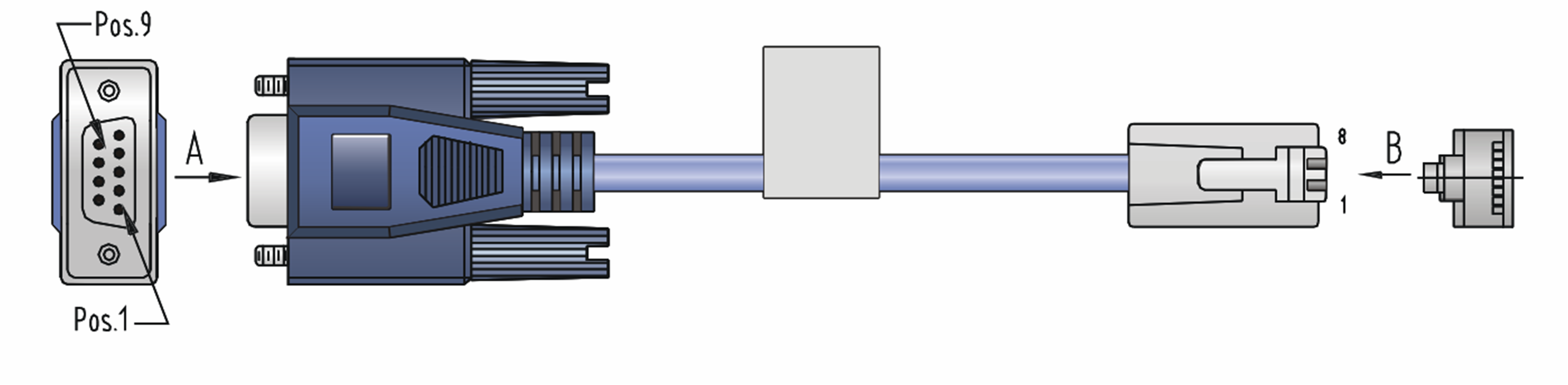
Table 4-1 Pinouts for the console cable connecting the serial port and the console port
|
RJ-45 pin |
Signal |
DB-9 pin |
Signal |
|
1 |
RTS |
8 |
CTS |
|
2 |
DTR |
6 |
DSR |
|
3 |
TXD |
2 |
RXD |
|
4 |
CD |
5 |
SG |
|
5 |
GND |
5 |
SG |
|
6 |
RXD |
3 |
TXD |
|
7 |
DSR |
4 |
DTR |
|
8 |
CTS |
7 |
RTS |
· Console cable connecting the USB console port on a switch and the USB port on a terminal
The console cable has one mini-USB A/B connector for connecting to the USB console port on the switch and one USB A connector for connecting to the USB port on the terminal.
Figure 4-2 shows the console cable and Table 4-2 shows its pinouts.
Figure 4-2 Console cable connecting the USB port and the USB console port
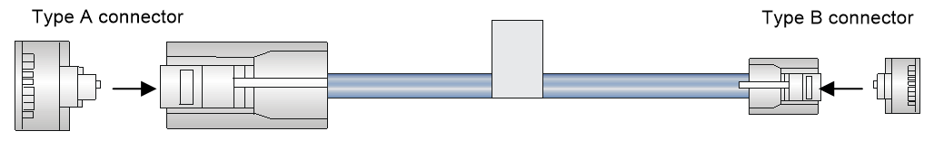
Table 4-2 Pinouts for the console cable connecting the USB port and the USB console port
|
USB A pin |
Signal |
mini-USB A/B pin |
Signal |
|
1 |
VBUS |
1 |
VBUS |
|
2 |
D- |
2 |
D- |
|
3 |
D+ |
3 |
D+ |
|
|
|
4 |
ID(NC) |
|
4 |
GND |
5 |
GND |
|
|
NOTE: If two MPUs are installed on a switch, you can use the console or USB console port on either of the MPU for connecting a terminal. |
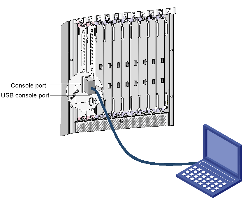
Connecting the console port to the terminal
|
|
IMPORTANT: · Identify the mark on the console and USB console port and make sure you are connecting to the correct port. · The serial ports on PCs do not support hot swapping. To connect a PC to an operating device, first connect the PC end. To disconnect a PC from an operating device, first disconnect the device end. |
To connect the console cable to the console port:
1. Connect the DB-9 connector of the console cable to the serial port on a PC or terminal.
2. Connect the RJ-45 connector of the console cable to the console port on the MPU of the switch.
To connect the console cable to the USB console port:
3. Connect the USB-A connector of the console cable to the USB port on a PC or terminal.
4. Connect the mini-USB A/B connector of the console cable to the USB console port on the MPU of the switch.
Figure 4-3 Connecting the console port to the terminal
Setting terminal parameters
To access the device through the console port, you must run a terminal emulator program, TeraTermPro or PuTTY, on the configuration terminal. For information about using a terminal emulator program, see the program's user guide.
The following are the required terminal settings:
· Baud rate—9600.
· Data bits—8.
· Stop bits—1.
· Parity—none.
· Flow control—none.
Powering on the switch
Before powering on the switch, confirm the following:
· You know where the emergency power-off switch for the equipment room is located.
· The switch has been securely mounted.
· All the cards have been correctly installed.
· The unused slots have been installed with filler panels.
· All the network cables, power cables, and grounding cables have been correctly connected.
· The input power voltage meets the requirement of the switch.
· The console cable is correctly connected, the terminal or PC used for configuration has started, and the configuration parameters have been set.
To power on the switch:
Turn on the power source of the switch to power on the switch.
The following is a sample output you can see on the terminal:
RAM test successful.
Press Ctrl+T to start five-step full RAM test...
Press Ctrl+Y to start nine-step full RAM test...
System is starting...
Press Ctrl+D to access BASIC-BOOTWARE MENU...
Booting Normal Extended BootWare
The Extended BootWare is self-decompressing......Done.
****************************************************************************
* *
* BootWare, Version 1.00 *
* *
****************************************************************************
Compiled Date : Jan 12 2017
CPU Type : XLP316
CPU Clock Speed : 1200MHz
Memory Type : DDR3 SDRAM
Memory Size : 8192MB
Memory Speed : 667MHz
BootWare Size : 1536KB
Flash Size : 4MB
BASIC CPLD Version : 001A
EXTENDED CPLD Version : 001A
PCB Version : Ver.A
BootWare Validating...
Press Ctrl+B to access EXTENDED-BOOTWARE MENU...
Loading the main image files...
Loading file flash:/S10500X-sytem.bin.........................
................................................................Done.
Loading file flash:/S10500X-boot.bin..........Done.
Image file flash:/S10500X-boot.bin is self-decompressing.......
.........................................Done.
System image is starting...
.
Cryptographic algorithms tests passed.
Line aux0 is available.
Press ENTER to get started.
Press Enter at the prompt. When the prompt <Sysname> appears, you can configure the switch.
After powering on the switch, check the following items:
· The cooling system is working, and you can hear fan rotating noise and feel air being blown out.
· The system status LEDs on the MPUs show that the system is operating correctly. For more information about LED behaviors, see "Appendix C LEDs."
Configuring the switch
By default, the switch does not authenticate the console login user at an AUX interface. To increase system security and enable remote management:
· Configure remote access services, for example, Telnet or SSH.
· Configure authentication on each user interface, including the AUX interfaces.
Configuring authentication on a user interface
You can configure authentication on a user interface to control access to the switch.
Table 4-3 describes the Telnet login authentication methods available for a VTY user interface.
Table 4-3 Telnet login authentication methods
|
Authentication method |
Feature |
Application scenarios |
|
None |
Easy to configure, allows any user to Telnet to your switch, and lowest in security |
Lab environments and extremely secure network environments |
|
Password |
Easy to configure, secure, and flat user management |
Environments that do not need granular privilege management |
|
Username and password |
Complex to configure, secure, and hierarchical user management |
Environments where multiple operators cooperate to manage the switch |
For more information about login methods, see H3C S10500X Switch Series Fundamentals Configuration Guide.
Connecting the switch to the network
Before you connect the switch to the network, verify that all its basic settings are correct.
Connecting your switch to the network through twisted pair cables
You can connect the 10/100BASE-TX ports, 1000BASE-T ports, and 10GBASE-T ports on your switch to the network. These ports use RJ-45 connectors and support MDI/MDI-X auto-sensing. Use category-6A or category-7 twisted pair cables to connect 10GBASE-T ports and category-5 or above to connect other ports. For more information about twisted pair cables, see H3C S10500X Switch Series Hardware Information and Specifications.
To connect a 10/100BASE-TX, a 1000BASE-T port, or a 10GBASE-T port to a peer device:
1. Connect one end of a twisted pair cable to the port.
2. Connect the other end of the twisted pair cable to the RJ-45 Ethernet port of the peer device.
3. Check the port LEDs for incorrect connection.
For more information about the LED status, see "Appendix C LEDs."
Connecting your switch to the network through optical fibers
|
|
WARNING! Disconnected optical fibers or transceiver modules might emit invisible laser light. Do not stare into beams or view directly with optical instruments when the switch is operating. |
You can install a transceiver module (see "(Optional) Installing transceiver modules and network cables.") in a fiber port and use optical fibers to connect the port to the network. For more information about optical fibers, see H3C S10500X Switch Series Hardware Information and Specifications.
To connect a fiber port to a peer device through optical fibers:
1. Install a transceiver module into the port.
2. Remove the dust cover of the optical fiber connector, and clean the end of the optical fiber.
3. Remove the dust plug of the transceiver module, connect one end of the optical fiber to the transceiver module, and connect the other end to the transceiver module in the peer device.
¡ For how to connect an LC connector, see Figure 4-4.
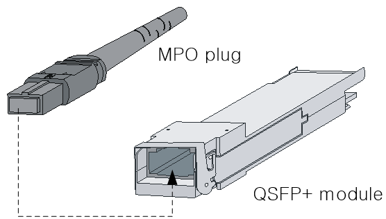
¡ For how to connect an MPO connector, see Figure 4-5.
4. Examine the port LEDs for incorrect connection.
For more information about the LED status, see "Appendix C LEDs."
|
|
NOTE: For the QSFP+ module, you do not need to differentiate between the transmitter (TX) and receiver (RX) ports. For other types of transceiver modules, the Tx port on one end must connect to the RX port on the other end. |
Figure 4-4 Using an LC optical fiber connector to connect an SFP module
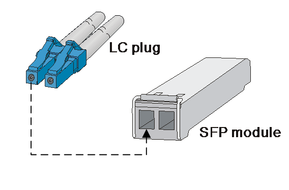
Figure 4-5 Using an MPO optical fiber connector to connect a QSFP module
Testing connectivity
After you connect the switch to the network, use the ping or tracert command to test the network connectivity. For more information about these commands, see H3C S10500X Switch Series Network Management and Monitoring Command References.