- Table of Contents
- Related Documents
-
| Title | Size | Download |
|---|---|---|
| 01-IGMP Configuration Examples | 106.88 KB |
Example: Configuring basic IGMP features
Applicable hardware and software versions
Example: Configuring IGMP static group members
Introduction
This document provides IGMP configuration examples.
Prerequisites
The configuration examples in this document were created and verified in a lab environment, and all the devices were started with the factory default configuration. When you are working on a live network, make sure you understand the potential impact of every command on your network.
This document assumes that you have basic knowledge of IGMP.
Example: Configuring basic IGMP features
Network configuration
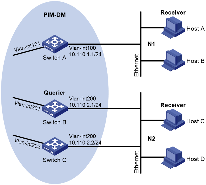
As shown in Figure 1:
· OSPF and PIM-DM run on the network.
· VOD streams are sent in multicast. Hosts of different organizations form stub networks N1 and N2.
· IGMPv2 runs between Switch A and N1, and between the other two switches and N2. Switch A acts as the IGMP querier in N1. Switch B acts as the IGMP querier in N2 because it has a lower IP address.
Configure basic IGMP features on the switches to meet the following requirements:
· Hosts in N1 can join any multicast groups.
· Hosts in N2 can join only multicast group 224.1.1.1.
Analysis
To limit the multicast groups that hosts can join, create an IPv4 basic ACL and specify the multicast groups that you want the hosts to join.
Applicable hardware and software versions
The following matrix shows the hardware and software versions to which this configuration example is applicable:
|
Hardware |
Software version |
|
S12500G-AF |
Release 8053P05 and later |
|
S12500CR |
Release 8053P05 and later |
|
S10500X-G |
Release 7753P05 and later |
|
S7500X-G |
Release 7753P05 and later |
Restrictions and guidelines
When you configure basic IGMP features, follow these restrictions and guidelines:
· The protocol packets of different IGMP versions are different in structures and types. For IGMP to operate correctly, you must enable the same IGMP version for all switches on the same subnet.
· You must configure the same multicast group policy for all switches on the same subnet.
· By default, Ethernet interfaces, VLAN interfaces, and aggregate interfaces are shut down. You must first use the undo shutdown command to bring them up. This example assumes that all these interfaces are already up.
Procedures
1. Assign an IP address and subnet mask to each interface, as shown in Figure 1. (Details not shown.)
2. Configure OSPF on the switches in the PIM-DM domain. (Details not shown.)
3. Configure Switch A:
# Enable IP multicast routing.
<SwitchA> system-view
[SwitchA] multicast routing
[SwitchA-mrib] quit
# Enable IGMP on the receiver-side interface VLAN-interface 100.
[SwitchA] interface vlan-interface 100
[SwitchA-Vlan-interface100] igmp enable
[SwitchA-Vlan-interface100] quit
# Enable PIM-DM on VLAN-interface 101.
[SwitchA] interface vlan-interface 101
[SwitchA-Vlan-interface101] pim dm
[SwitchA-Vlan-interface101] quit
4. Configure Switch B:
# Create ACL 2001 to permit IGMP reports for multicast group 224.1.1.1.
<SwitchB> system-view
[SwitchB] acl basic 2001
[SwitchB-acl-ipv4-basic-2001] rule permit source 224.1.1.1 0
[SwitchB-acl-ipv4-basic-2001] quit
# Enable IP multicast routing.
[SwitchB] multicast routing
[SwitchB-mrib] quit
# Enable IGMP on the receiver-side interface VLAN-interface 200.
[SwitchB] interface vlan-interface 200
[SwitchB-Vlan-interface200] igmp enable
# Configure a multicast group policy that uses ACL 2001.
[SwitchB-Vlan-interface200] igmp group-policy 2001
[SwitchB-Vlan-interface200] quit
# Enable PIM-DM on VLAN-interface 201.
[SwitchB] interface vlan-interface 201
[SwitchB-Vlan-interface201] pim dm
[SwitchB-Vlan-interface201] quit
5. Configure Switch C:
# Create ACL 2001 to permit IGMP reports for multicast group 224.1.1.1.
<SwitchC> system-view
[SwitchC] acl basic 2001
[SwitchC-acl-ipv4-basic-2001] rule permit source 224.1.1.1 0
[SwitchC-acl-ipv4-basic-2001] quit
# Enable IP multicast routing.
[SwitchC] multicast routing
[SwitchC-mrib] quit
# Enable IGMP on the receiver-side interface VLAN-interface 200.
[SwitchC] interface vlan-interface 200
[SwitchC-Vlan-interface200] igmp enable
# Configure a multicast group policy that uses ACL 2001.
[SwitchC-Vlan-interface200] igmp group-policy 2001
[SwitchC-Vlan-interface200] quit
# Enable PIM-DM on VLAN-interface 202.
[SwitchC] interface vlan-interface 202
[SwitchC-Vlan-interface202] pim dm
[SwitchC-Vlan-interface202] quit
Verifying the configuration
1. Verify that hosts in N1 can join the multicast groups 224.1.1.1 and 224.1.1.2:
# Send IGMP reports from Host A (10.110.1.10) to join the multicast groups 224.1.1.1 and 224.1.1.2. (Details not shown.)
# Display information about IGMP groups that hosts have dynamically joined on Switch A.
[SwitchA] display igmp group
IGMP groups in total: 2
Vlan-interface100 (10.110.1.1):
IGMP groups reported in total: 2
Group address Last reporter Uptime Expires
224.1.1.1 10.110.1.10 00:02:04 00:01:15
224.1.1.2 10.110.1.10 00:02:00 00:01:19
The output shows that Host A has joined the multicast groups 224.1.1.1 and 224.1.1.2.
2. Verify that hosts in N2 can join only multicast group 224.1.1.1:
# Send IGMP reports from Host C (10.110.2.10) to join the multicast groups 224.1.1.1 and 224.1.1.2. (Details not shown.)
# Display information about IGMP groups that hosts have dynamically joined on Switch B.
[SwitchB] display igmp group
IGMP groups in total: 1
Vlan-interface200(10.110.2.1):
IGMP groups reported in total: 1
Group address Last reporter Uptime Expires
224.1.1.1 10.110.2.10 04:36:03 00:01:23
# Display information about IGMP groups that hosts have dynamically joined on Switch C.
[SwitchC] display igmp group
IGMP groups in total: 1
Vlan-interface200(10.110.2.2):
IGMP groups reported in total: 1
Group address Last reporter Uptime Expires
224.1.1.1 10.110.2.10 04:21:03 00:01:13
The output shows that Switch B and Switch C each have IGMP information about only the multicast group, 224.1.1.1. The multicast group policy has taken effect, and hosts in N2 can join only multicast group 224.1.1.1.
Configuration files
· Switch A:
#
vlan 100 to 101
#
interface Vlan-interface100
ip address 10.110.1.1 255.255.255.0
igmp enable
#
interface Vlan-interface101
ip address 10.111.1.1 255.255.255.0
pim dm
#
interface Ten-GigabitEthernet3/0/1
port link-mode bridge
port access vlan 100
#
interface Ten-GigabitEthernet3/0/2
port link-mode bridge
port access vlan 101
#
multicast routing
#
· Switch B:
#
acl basic 2001
rule 0 permit source 224.1.1.1 0
#
vlan 200 to 201
#
interface Vlan-interface200
ip address 10.110.2.1 255.255.255.0
igmp enable
igmp group-policy 2001
#
interface Vlan-interface201
ip address 10.111.2.1 255.255.255.0
pim dm
#
interface Ten-GigabitEthernet3/0/1
port link-mode bridge
port access vlan 200
#
interface Ten-GigabitEthernet3/0/2
port link-mode bridge
port access vlan 201
#
multicast routing
#
· Switch C:
#
acl basic 2001
rule 0 permit source 224.1.1.1 0
#
vlan 200
#
vlan 202
#
interface Vlan-interface200
ip address 10.110.2.2 255.255.255.0
igmp enable
igmp group-policy 2001
#
interface Vlan-interface202
ip address 10.111.3.1 255.255.255.0
pim dm
#
interface Ten-GigabitEthernet3/0/1
port link-mode bridge
port access vlan 200
#
interface Ten-GigabitEthernet3/0/2
port link-mode bridge
port access vlan 202
#
multicast routing
#
Example: Configuring IGMP static group members
Network configuration
As shown in Figure 2:
· OSPF and PIM-DM run on the network.
· VOD streams are sent in multicast. Hosts of different organizations form stub networks N1 and N2.
· IGMPv2 runs between Switch A and N1, and between the other two switches and N2. Switch A acts as the IGMP querier in N1. Switch B acts as the IGMP querier in N2 because it has a lower IP address.
Configure the switches to meet the following requirements:
· Hosts in N1 can join any multicast groups, and Host A can permanently receive multicast data addressed to multicast group 224.1.1.2.
· Hosts in N2 can join only multicast group 224.1.1.1.

Analysis
For Host A to permanently receive multicast data addressed to the group 224.1.1.2, configure VLAN-interface 100 on Switch A as a static member of the multicast group.
To limit the multicast groups that hosts can join, create an IPv4 basic ACL and specify the multicast groups that you want the hosts to join.
Applicable hardware and software versions
The following matrix shows the hardware and software versions to which this configuration example is applicable:
|
Hardware |
Software version |
|
S12500G-AF |
Release 8053P05 and later |
|
S12500CR |
Release 8053P05 and later |
|
S10500X-G |
Release 7753P05 and later |
|
S7500X-G |
Release 7753P05 and later |
Restrictions and guidelines
When you configure IGMP static group member ports, follow these restrictions and guidelines:
· The protocol packets of different IGMP versions are different in structures and types. For IGMP to operate correctly, specify the same IGMP version for all switches on the same subnet.
· You must configure the same multicast group policy for all switches on the same subnet.
· By default, Ethernet interfaces, VLAN interfaces, and aggregate interfaces are shut down. You must first use the undo shutdown command to bring them up. This example assumes that all these interfaces are already up.
Procedures
1. Assign an IP address and subnet mask to each interface, as shown in Figure 2. (Details not shown.)
2. Configure OSPF on the switches in the PIM-DM domain. (Details not shown.)
3. Configure Switch A:
# Enable IP multicast routing.
<SwitchA> system-view
[SwitchA] multicast routing
[SwitchA-mrib] quit
# Enable PIM-DM on VLAN-interface 101.
[SwitchA] interface vlan-interface 101
[SwitchA-Vlan-interface101] pim dm
[SwitchA-Vlan-interface101] quit
# Enable IGMP on the receiver-side interface VLAN-interface 100.
[SwitchA] interface vlan-interface 100
[SwitchA-Vlan-interface100] igmp enable
# Configure VLAN-interface 100 as a static member of multicast group 224.1.1.2.
[SwitchA-Vlan-interface100] igmp static-group 224.1.1.2
[SwitchA-Vlan-interface100] quit
4. Configure Switch B:
# Enable IP multicast routing.
<SwitchB> system-view
[SwitchB] multicast routing
[SwitchB-mrib] quit
# Enable PIM-DM on VLAN-interface 201.
[SwitchB] interface vlan-interface 201
[SwitchB-Vlan-interface201] pim dm
[SwitchB-Vlan-interface201] quit
# Create ACL 2001 to permit IGMP reports for multicast group 224.1.1.1.
[SwitchB] acl basic 2001
[SwitchB-acl-ipv4-basic-2001] rule permit source 224.1.1.1 0
[SwitchB-acl-ipv4-basic-2001] quit
# Enable IGMP on the receiver-side interface VLAN-interface 200.
[SwitchB] interface vlan-interface 200
[SwitchB-Vlan-interface200] igmp enable
# Configure a multicast group policy that uses ACL 2001.
[SwitchB-Vlan-interface200] igmp group-policy 2001
[SwitchB-Vlan-interface200] quit
5. Configure Switch C:
# Enable IP multicast routing.
<SwitchC> system-view
[SwitchC] multicast routing
[SwitchC-mrib] quit
# Enable PIM-DM on VLAN-interface 202.
[SwitchC] interface vlan-interface 202
[SwitchC-Vlan-interface202] pim dm
[SwitchC-Vlan-interface202] quit
# Create ACL 2001 to permit IGMP reports for multicast group 224.1.1.1.
[SwitchC] acl basic 2001
[SwitchC-acl-ipv4-basic-2001] rule permit source 224.1.1.1 0
[SwitchC-acl-ipv4-basic-2001] quit
# Enable IGMP on VLAN-interface 200.
[SwitchC] interface vlan-interface 200
[SwitchC-Vlan-interface200] igmp enable
# Configure a multicast group policy that uses ACL 2001.
[SwitchC-Vlan-interface200] igmp group-policy 2001
[SwitchC-Vlan-interface200] quit
Verifying the configuration
1. Verify that hosts in N1 can join the multicast groups 224.1.1.1 and 224.1.1.2:
# Send IGMP reports from Host A (10.110.1.10) to join the multicast groups 224.1.1.1 and 224.1.1.2. (Details not shown.)
# Display information about IGMP groups that hosts have dynamically joined on Switch A.
[SwitchA] display igmp group
IGMP groups in total: 2.
Vlan-interface100 (10.110.1.1):
IGMP groups reported in total: 2
Group address Last reporter Uptime Expires
224.1.1.1 10.110.1.10 00:02:04 00:01:15
224.1.1.2 10.110.1.10 00:02:00 00:01:19
The output shows that Host A has dynamically joined the multicast groups 224.1.1.1 and 224.1.1.2.
# Display information about IGMP groups that hosts have statically joined on Switch A.
[SwitchA] display igmp group static
Entries in total: 1
Group address Source address Interface Expires
224.1.1.2 0.0.0.0 Vlan100 Never
The output shows that Host A has statically joined multicast group 224.1.1.1 through VLAN-interface 100.
2. Verify that hosts in N2 can join only multicast group 224.1.1.1:
# Send IGMP reports from Host C (10.110.2.10) to join multicast groups 224.1.1.1 and 224.1.1.2. (Details not shown.)
# Display information about IGMP groups that hosts have dynamically joined on Switch B.
[SwitchB] display igmp group
IGMP groups in total: 1
Vlan-interface200(10.110.2.1):
IGMP groups reported in total: 1
Group address Last reporter Uptime Expires
224.1.1.1 10.110.2.10 04:36:03 00:01:23
# Display information about IGMP groups that hosts have dynamically joined on Switch C.
[SwitchC] display igmp group
IGMP groups in total: 1
Vlan-interface200(10.110.2.2):
IGMP groups reported in total: 1
Group address Last reporter Uptime Expires
224.1.1.1 10.110.2.10 04:21:03 00:01:13
The output shows that Switch B and Switch C each have information only about multicast group 224.1.1.1. The multicast group policy has taken effect, and hosts in N2 can join only multicast group 224.1.1.1.
Configuration files
· Switch A:
#
vlan 100 to 101
#
interface Vlan-interface100
ip address 10.110.1.1 255.255.255.0
igmp enable
igmp static-group 224.1.1.2
#
interface Vlan-interface101
ip address 10.111.1.1 255.255.255.0
pim dm
#
interface Ten-GigabitEthernet3/0/1
port link-mode bridge
port access vlan 100
#
interface Ten-GigabitEthernet3/0/2
port link-mode bridge
port access vlan 101
#
multicast routing
#
· Switch B:
#
acl basic 2001
rule 0 permit source 224.1.1.1 0
#
vlan 200 to 201
#
interface Vlan-interface200
ip address 10.110.2.1 255.255.255.0
igmp enable
igmp group-policy 2001
#
interface Vlan-interface201
ip address 10.111.2.1 255.255.255.0
pim dm
#
interface Ten-GigabitEthernet3/0/1
port link-mode bridge
port access vlan 200
#
interface Ten-GigabitEthernet3/0/2
port link-mode bridge
port access vlan 201
#
multicast routing
#
· Switch C:
#
acl basic 2001
rule 0 permit source 224.1.1.1 0
#
vlan 200
#
vlan 202
#
interface Vlan-interface200
ip address 10.110.2.2 255.255.255.0
igmp enable
igmp group-policy 2001
#
interface Vlan-interface202
ip address 10.111.3.1 255.255.255.0
pim dm
#
interface Ten-GigabitEthernet3/0/1
port link-mode bridge
port access vlan 200
#
interface Ten-GigabitEthernet3/0/2
port link-mode bridge
port access vlan 202
#
multicast routing
#