- Table of Contents
-
- 12-High Availability Configuration Guides
- 00-Preface
- 01-Ethernet OAM configuration
- 02-CFD configuration
- 03-DLDP configuration
- 04-RRPP configuration
- 05-ERPS configuration
- 06-Smart Link configuration
- 07-Monitor Link configuration
- 08-VRRP configuration
- 09-Error code detection configuration
- 09-Reth interface and redundancy group configuration
- 10-BFD configuration
- 11-Track configuration
- 13-Process placement configuration
- Related Documents
-
| Title | Size | Download |
|---|---|---|
| 05-ERPS configuration | 522.60 KB |
Enabling flush packet transparent transmission
Enabling R-APS packets to carry the ring ID in the destination MAC address
Configuring ERPS ring member ports
Configuring ERPS ring member port attributes
Configuring an ERPS ring member port
Configuring R-APS packet levels
Setting the non-revertive mode
Associating a ring with a subring
Associating an ERPS ring member port with a track entry
Removing the MS mode and FS mode settings for an ERPS ring
Displaying and maintaining ERPS
One-ring configuration example
One-subring configuration example
One-ring multi-instance load balancing configuration example
Configuring ERPS
Overview
Ethernet Ring Protection Switching (ERPS) is a robust link layer protocol that ensures a loop-free topology and implements quick link recovery.
ERPS structure
Rings
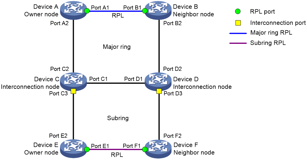
ERPS rings can be divided into major rings and subrings. An ERPS network consists of one major ring or multiple major rings, and multiple subrings. By default, a ring is a major ring. You can configure a ring as a subring manually.
As shown in Figure 1, a major ring is a closed ring formed by Device A, Device B, Device C, and Device D. A subring is an open ring formed by the link Device C<—>Device E<—>Device F<—>Device D.
Nodes
ERPS nodes include owner nodes, neighbor nodes, interconnection nodes, and normal nodes.
· The owner node and neighbor node block and unblock ports on the ring protection link (RPL) to prevent loops and switch traffic. An RPL connects an owner node and a neighbor node.
· Interconnection nodes connect different rings. Interconnection nodes reside on subrings and forward service packets but not protocol packets.
· Normal nodes forward both service packets and protocol packets.
As shown in Figure 1, on the major ring, Device A is the owner node and Device B is the neighbor node. On the subring, Device E is the owner node and Device F is the neighbor node. Devices C and D are interconnection nodes.
Ports
Each node consists of two ERPS ring member ports: Port 0 and port 1. ERPS ring member ports have the following types:
· RPL port—Port on an RPL link.
· Interconnection port—Port that connects a subring to a major ring.
· Normal port—Default type of a port that forwards both service packets and protocol packets.
As shown in Figure 1, ports A1, B1, E1, and F1 are RPL ports. Ports C3 and D3 are interconnection ports. Other ports are normal ports.
Instances
An ERPS ring supports multiple ERPS instances. An ERPS instance is a logical ring to process service and protocol packets. Each ERPS instance has its own owner node and maintains its own state and data. An ERPS instance is uniquely identified by the ring ID and VLAN ID of ERPS packets. The ring ID indicates the ring of ERPS packets. It can be represented by the last byte in the destination MAC address of the packets. The VLAN ID indicates the ERPS instance of the packets.
ERPS protocol packets
ERPS protocol packets are Ring Automatic Protection Switching (R-APS) packets. You can configure the R-APS packet level. A node does not process R-APS packets whose levels are greater than the level of the packets sent by the node. On a ring, the levels of R-APS packets must be the same for all nodes in an ERPS instance.
Table 1 R-APS packet types and functions
|
Packet type |
Function |
|
No request, RPL block (NR-RB) |
When the link is stable, an owner node in idle state periodically sends NR-RB packets to inform other nodes that the RPL ports are blocked. The nodes that receive the NR-RB packets unblock available ports and update MAC address entries. |
|
No request (NR) |
After the link fault is cleared, the node that detects the recovery periodically sends NR packets. When the owner node receives the NR packets, it starts the WTR timer. The node stops sending NR packets after receiving NR-RB packets from the owner node. |
|
Signal fail (SF) |
When a link fails to send or receive signals, the node that detects the fault periodically sends SF packets. When the owner node and neighbor node receive the FS packets, they unblock the RPL ports. The node stops sending SF packets after the fault is cleared. |
|
Manual switch (MS) |
A port configured with the MS mode is blocked and periodically sends MS packets. When other nodes receive the MS packets, they unblock available ports and update MAC address entries. |
|
Forced switch (FS) |
A port configured with the FS mode is blocked and periodically sends FS packets. When other nodes receive the FS packets, they unblock all ports and update MAC address entries. |
|
Flush |
If the topology of a subring changes, the interconnection ports on the subring broadcasts flush packets. All nodes that receive the flush packets update MAC address entries. |
|
|
NOTE: · Typically R-APS packets are transmitted within a ring. The flush packets sourced from the subring can be forwarded to the major ring. · Service packets can be transmitted between different rings. |
ERPS node states
Table 2 ERPS states
|
State |
Description |
|
Init |
State for a non-interconnection node that has less than two ERPS ring member ports or for an interconnection node that does not have ERPS ring member ports. |
|
Idle |
Stable state when all non-RPL links are available. In this state, the owner node blocks the RPL port and periodically sends NR-RB packets. The neighbor node blocks the RPL port. All nodes enter the idle state after the owner node enters the idle state. |
|
Protection |
State when a non-RPL link is faulty. In this state, the RPL link is unblocked to forward traffic. All nodes enter the protection state after a node enters the protection state. |
|
MS |
State when traffic paths are manually switched. All nodes enter the MS state after a node is configured with the MS mode. |
|
FS |
State when traffic paths are forcibly switched. All nodes enter the FS state after a node is configured with the FS mode. |
|
Pending |
Transient state between the previous states. |
ERPS timers
|
Timer |
Description |
Impact |
|
Hold-off |
The hold-off timer starts when the port detects a link fault. The port reports the link fault if the fault persists when the timer expires. |
This timer delays the fault report time and affects the link switching performance. |
|
Guard |
The guard timer starts when the port detects a link recovery. The port does not process R-APS packets before the timer expires. |
This timer prevents R-APS packets from impacting the network and affects the link switching performance when multiple points of failures exist. |
|
WTR |
In revertive mode, the WTR timer starts when the owner node in protection state receives NR packets. The RPL is unblocked and the recovered node is blocked before the timer expires. The owner node blocks the RPL and sends NR-RB packets when the timer expires. If the port receives SF packets before the timer expires, the timer stops and the RPL remains unblocked. |
This timer prevents intermittent link failures from impacting the network. |
|
WTB |
In revertive mode, the WTB timer starts when the owner node in MS or FS state receives NR packets. The RPL is unblocked and the recovered node sends NR packets before the timer expires. The owner node blocks the RPL and sends NR-RB packets when the timer expires. If the port receives SF packets before the timer expires, the timer stops and the RPL remains unblocked. |
This timer prevents the RPL ports from being blocked and unblocked frequently. |
ERPS operation mechanism
ERPS uses the detection mechanism defined in ITU-T G.8032/Y.1344 to locate the point of failure and identify unidirectional or bidirectional faults.
ERPS uses the SF packets to report signal failures on a link and the NR packets to report link recovery. When a node detects a link status change, the node sends three packets first and then sends subsequent packets every five seconds.
Link-down report mechanism
Figure 2 Link-down report mechanism
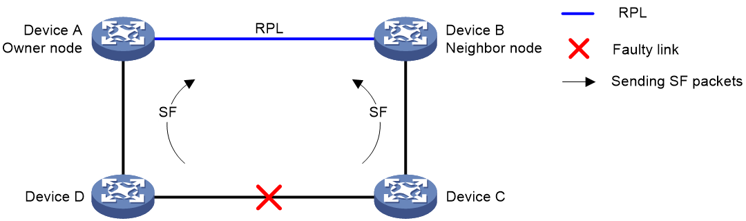
As shown in Figure 2, the link-down report mechanism uses the following process:
1. Device C and Device D detect the link failure and perform the following operations:
a. Block the ports on both side of the faulty link.
b. Periodically send SF packets to other nodes.
2. Device A and Device B receive the SF packets and perform the following operations:
a. Unblock RPL ports.
b. Update the MAC address entries.
Service packets are switched to the RPL link.
Link recovery mechanism
Figure 3 Link recovery mechanism
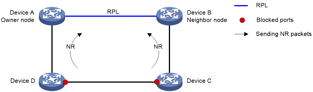
As shown in Figure 3, the link recovery mechanism uses the following process:
1. Device C and Device D detect the link recovery and perform the following operations:
a. Block the recovered ports.
b. Start the guard timer.
c. Send NR packets.
2. When Device A (owner node) receives the NR packets, it does not perform any operations if it is in non-revertive mode. If Device A is in revertive mode, it performs the following operations:
a. Starts the WTR timer.
b. Blocks the RPL port and periodically sends NR-RB packets when the WTR timer expires.
3. When other nodes receive the NR-RB packets, they perform the following operations:
a. Device B (neighbor port) blocks the RPL port.
b. Device C and Device D unblock the recovered ports.
Service packets are switched to the recovered link.
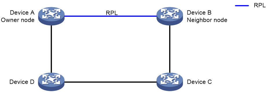
Multi-instance load balancing mechanism
Figure 4 Multi-instance load balancing mechanism

An ERPS ring topology might carry traffic from multiple VLANs. Traffic from different VLANs can be load balanced among different ERPS instances.
ERPS uses the following types of VLANs:
· Control VLAN—Carries ERPS protocol packets. The system determines the control VLANs for ERPS ring member ports. Each ERPS instance has its own control VLAN.
· Protected VLAN—Carries data packets. Each ERPS instance has its own protected VLAN. Protected VLANs are configured by using the mappings between VLANs and MSTIs.
As shown in Figure 4, the ERPS ring is configured with instance 1 and instance 2. For instance 1, the owner node is Device A, and the RPL is the link between Device A and Device B. For instance 2, the owner node is Device C, and the RPL is the link between Device C and Device D. Traffic from different VLANs can be load balanced among different links.
Manual configuration mechanism
ERPS supports the following manual configuration modes:
· MS—Use the erps switch manual command to block an ERPS ring member port. A port in MS mode is blocked and sends MS packets. The nodes that receive the MS packets unblock available ports. If the nodes in MS mode receive an SF packet, they unblock the blocked ports.
· FS—Use the erps switch force ring command to block an ERPS ring member port. A port in FS mode is blocked and sends FS packets. The nodes that receive the FS packets unblock available ports. If the nodes in FS mode receive an SF packet, they do not unblock the blocked ports.
Collaboration mechanism
To detect and clear link faults typically for a fiber link, use ERPS with CFD and Track. You can associate ERPS ring member ports with the continuity check function of CFD through track entries. CFD reports link events only when the monitored VLAN is the control VLAN of the ERPS instance for the port. For more information about CFD and Track, see "Configuring CFD" and "Configuring Track."
ERPS network diagrams
One major ring
The network has one major ring.
Figure 5 Network diagram
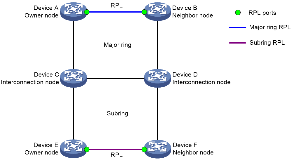
One major ring connecting one subring
The network has one major ring and one subring.
Figure 6 Network diagram
One major ring connecting multiple subrings
The network has three or more rings. Each subring is connected to the major ring by two interconnection nodes.
Figure 7 Network diagram
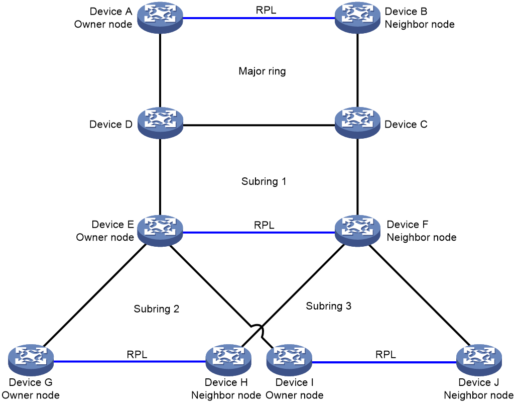
One subring connecting multiple subrings
The network has three or more rings. As shown in Figure 8, subring 1 is connected to the major ring. Other subrings are connected to subring 1 by two interconnection nodes.
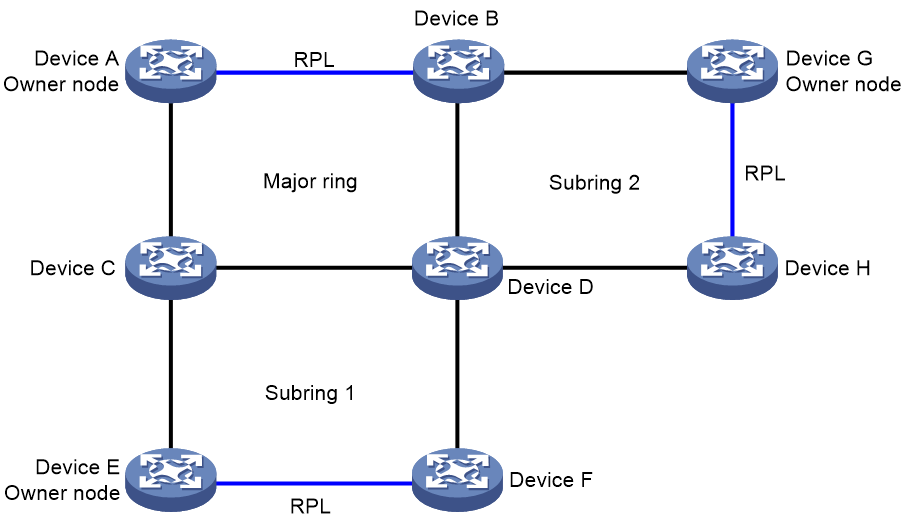
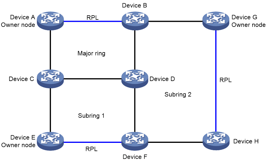
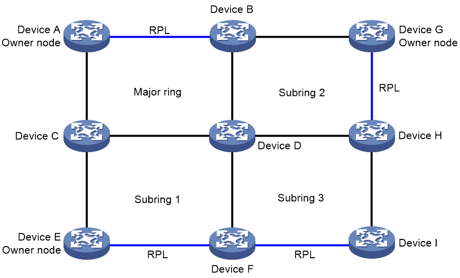
One subring connecting multiple rings
The network has three or more rings. A minimum of one subring is connected to two rings. As shown in Figure 9, one interconnection node on subring 2 is connected to the major ring; and another interconnection node is connected to subring 1. As shown in Figure 10, subring 3 is connected to subring 1 and subring 2.
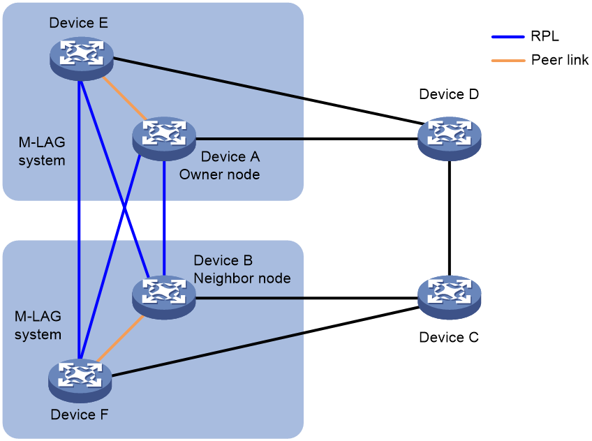
ERPS with M-LAG
M-LAG allows you to virtualize the devices in an ERPS ring into one system through multichassis link to achieve device-level redundancy and load balancing.
You can use the display erps detail ring command to determine whether ERPS works correctly in an M-LAG network. For more information about M-LAG, see Layer 2—LAN Switching Configuration Guide.
Figure 11 ERPS with M-LAG
Protocols and standards
· ITU-T G.8032, Recommendation ITU-T G.8032/Y.1344, Ethernet ring protection switching
· IEEE 802.1D, IEEE Std 802.1D™-2004, IEEE Standard for Local and Metropolitan Area Networks—Media Access Control (MAC) Bridges
· IEEE 802.3, IEEE Std 802.3-2008, IEEE Standard for Information technology
ERPS configuration task list
ERPS does not provide an election mechanism. To implement ring detection and protection, configure all nodes correctly.
To configure ERPS, perform the following tasks:
Configuration prerequisites
Before you configure ERPS, complete the following tasks:
· Establish the Ethernet ring topology.
· Determine the ERPS rings, ERPS instances, control VLANs, protected VLANs, and node roles.
Enabling ERPS globally
For ERPS to take effect for an instance, enable it globally first.
To enable ERPS globally:
|
Step |
Command |
Remarks |
|
1. Enter system view. |
system-view |
N/A |
|
2. Enable ERPS globally. |
erps enable |
By default, ERPS is disabled globally. |
Enabling flush packet transparent transmission
This feature enables the interconnection nodes to forward flush packets for topology changes in the subring to the major ring.
To enable flush packet transparent transmission:
|
Step |
Command |
Remarks |
|
1. Enter system view. |
system-view |
N/A |
|
2. Enable flush packet transparent transmission. |
erps tcn-propagation |
By default, flush packet transparent transmission is disabled. |
Configuring an ERPS ring
|
Step |
Command |
Remarks |
|
1. Enter system view. |
system-view |
N/A |
|
2. Create an ERPS ring. |
erps ring ring-id |
A ring ID uniquely identifies an ERPS ring. All nodes on an ERPS ring must be configured with the same ring ID. |
|
3. (Optional.) Configure the ring type. |
ring-type sub-ring |
By default, an ERPS ring is a major ring. |
Enabling R-APS packets to carry the ring ID in the destination MAC address
Perform this task to configure the ring ID as the last byte of the destination MAC address for R-APS packets. The ring of R-APS packets can be identified by their destination MAC addresses.
To enable R-APS packets to carry the ring ID in the destination MAC address:
|
Step |
Command |
Remarks |
|
1. Enter system view. |
system-view |
N/A |
|
2. Enter ERPS ring view. |
erps ring ring-id |
N/A |
|
3. Enable R-APS packets to carry the ring ID in the destination MAC address. |
r-aps ring-mac |
By default, R-APS packets do not carry ring IDs in their destination MAC addresses. The last byte of the destination MAC address is 1. |
Configuring ERPS ring member ports
You can configure the ERPS ring member ports before configuring ERPS instances.
Configuring ERPS ring member port attributes
Follow these guidelines when you configure ERPS ring member port attributes:
· ERPS ring member ports automatically allow packets from the control VLAN to pass through.
· Do not enable Ethernet OAM remote loopback for ERPS ring member ports. This feature might cause a broadcast storm. For more information about Ethernet OAM, see "Configuring Ethernet OAM."
· For faster topology convergence, use the link-delay command on ERPS ring member ports to set the physical state change suppression interval to 0 seconds. For more information about the link-delay command, see Interface Command Reference.
· You must configure ERPS ring member ports as trunk ports.
· Do not assign an interface to both an aggregation group and an ERPS ring. If you do so, the interface does not take effect on the ERPS ring and cannot be displayed by using the display erps detail command.
· Do not assign a peer-link interface to an ERPS ring. A peer-link interface does not work for an ERPS ring and cannot be displayed by using the display erps detail command.
· Do not assign both an M-LAG interface and a non-M-LAG interface on a non-interconnection node to an ERPS ring. If you do so, the M-LAG interface does not take effect on the ERPS ring.
To configure ERPS ring member port attributes:
|
Step |
Command |
Remarks |
|
1. Enter system view. |
system-view |
N/A |
|
2. Enter Layer 2 Ethernet interface view or Layer 2 aggregate interface view. |
interface interface-type interface-number |
N/A |
|
3. Configure the port as a trunk port. |
port link-type trunk |
By default, a port is an access port. For more information about this command, see Layer 2—LAN Switching Command Reference. |
|
4. Assign the trunk port to protected VLANs. |
port trunk permit vlan { vlan-id-list | all } |
By default, a trunk port is assigned only to VLAN 1. For more information about this command, see Layer 2—LAN Switching Command Reference. |
|
5. Disable the spanning tree feature. |
undo stp enable |
By default, the spanning tree feature is enabled. For more information about this command, see Layer 2—LAN Switching Command Reference. |
Configuring an ERPS ring member port
Only trunk ports can be configured as the ERPS ring member ports.
To configure an ERPS ring member port:
|
Step |
Command |
Remarks |
|
1. Enter system view. |
system-view |
N/A |
|
2. Enter ERPS ring view. |
erps ring ring-id |
N/A |
|
3. Configure an ERPS ring member port. |
{ port0 | port1 } interface interface-type interface-number |
By default, an ERPS ring does not have ERPS ring member ports. |
Configuring control VLANs
Follow these guidelines when you configure control VLANs:
· The control VLAN must be a VLAN that has not been created on the device.
· Configure the same control VLAN for all nodes in an ERPS instance.
· Do not configure the default VLAN of an ERPS ring member port as the control VLAN, and do not enable QinQ or VLAN mapping on control VLANs. If you do, ERPS packets cannot be correctly forwarded and received.
· Make sure the ERPS instance has been configured. After the ERPS instance is enabled, the control VLAN cannot be changed.
· For a device that connects two rings to forward Flush packets correctly, make sure only the ports that connect to the ERPS rings are configured with the control VLAN.
· For a device not configured with ERPS to transparently transmit ERPS packets, make sure only the two ports accessing the ERPS ring permit packets from the control VLAN. If other ports on the device permit packets from the control VLAN, the packets from other VLANs might enter the control VLAN and strike the ERPS ring.
· When configuring ERPS with M-LAG, make sure the peer-link interface is a trunk port. The peer-link interface will automatically join or leave a control VLAN as the control VLAN is created or deleted.
To configure a control VLAN:
|
Step |
Command |
Remarks |
|
1. Enter system view. |
system-view |
N/A |
|
2. Enter ERPS ring view. |
erps ring ring-id |
N/A |
|
3. Enable ERPS instance view. |
instance instance-id |
N/A |
|
4. Configure a control VLAN. |
control-vlan vlan-id |
By default, an ERPS instance does not have control VLANs. |
Configuring protected VLANs
Configure the same protected VLAN for all nodes of an ERPS instance. To implement load balancing, configure different protected VLANs for different ERPS instances.
Protected VLANs are configured by referencing MSTIs. The protected VLAN configuration method varies by the spanning tree mode:
· In STP, RSTP, or MSTP mode, you must manually configure the mappings between VLANs and MSTIs.
· In PVST mode, the device automatically maps each VLAN to an MSTI. When the spanning tree protocol is disabled globally, all VLANs are automatically mapped to MSTI 0.
For more information about MSTI and PVST, see Layer 2—LAN Switching Configuration Guide.
To configure protected VLANs:
|
Step |
Command |
Remarks |
|
1. Enter system view. |
system-view |
N/A |
|
2. Enter MST region view. |
stp region-configuration |
This step is not required if the device is operating in PVST mode. For more information about this command, see Layer 2—LAN Switching Command Reference. |
|
3. Map VLANs to MSTIs. |
· Method 1: · Method 2: |
By default, all VLANs are mapped to MSTI 0 (CIST). This step is not required if the device is operating in PVST mode. For more information about these commands, see Layer 2—LAN Switching Command Reference. |
|
4. Activate the MST region configuration. |
active region-configuration |
This step is not required if the device is operating in PVST mode. For more information about this command, see Layer 2—LAN Switching Command Reference. |
|
5. (Optional.) Display the mapping between VLANs and MSTIs. |
display stp region-configuration |
Available in any view. The output of the command includes VLAN-to-instance mappings. For more information about this command, see Layer 2—LAN Switching Command Reference. |
|
6. Return to system view. |
quit |
This step is not required if the device is operating in PVST mode. |
|
7. Enter ERPS ring view. |
erps ring ring-id |
N/A |
|
8. Enable ERPS instance view. |
instance instance-id |
N/A |
|
9. Configure the protected VLANs. |
protected-vlan reference-instance instance-id-list |
By default, an ERPS instance does not have protected VLANs. |
Configuring the node role
Perform this task on all nodes on an ERPS ring.
For the owner node to work correctly, you must configure only one owner node for an ERPS ring.
You can only configure the interconnection node for subrings.
To configure the node role:
|
Step |
Command |
Remarks |
|
1. Enter system view. |
system-view |
N/A |
|
2. Enter ERPS ring view. |
erps ring ring-id |
N/A |
|
3. Enter ERPS instance view. |
instance instance-id |
N/A |
|
4. Configure the node role. |
node-role { { owner | neighbor } rpl | interconnection } { port0 | port1 } |
By default, a node is a normal node. |
Enabling ERPS for an instance
You can enable ERPS for an instance only when it is configured with a control VLAN and a protected VLAN.
To enable ERPS for an instance:
|
Step |
Command |
Remarks |
|
1. Enter system view. |
system-view |
N/A |
|
2. Enter ERPS ring view. |
erps ring ring-id |
N/A |
|
3. Enter ERPS instance view. |
instance instance-id |
N/A |
|
4. Enable ERPS for the instance. |
instance enable |
By default, ERPS is disabled for an instance. |
Configuring R-APS packet levels
A node does not process R-APS packets whose levels are greater than the level of R-APS packets sent by the node. On a ring, the levels of R-APS packets must be the same for all nodes in an ERPS instance.
To configure the R-APS packet level:
|
Step |
Command |
Remarks |
|
1. Enter system view. |
system-view |
N/A |
|
2. Enter ERPS ring view. |
erps ring ring-id |
N/A |
|
3. Enter ERPS instance view. |
instance instance-id |
N/A |
|
4. Configure the R-APS packet level. |
r-aps level level-value |
By default, the level for R-APS packets is 7. |
Setting ERPS timers
|
Step |
Command |
Remarks |
|
1. Enter system view. |
system-view |
N/A |
|
2. Enter ERPS ring view. |
erps ring ring-id |
N/A |
|
3. Enter ERPS instance view. |
instance instance-id |
N/A |
|
4. Set the guard timer. |
timer guard guard-value |
By default, the guard timer is 500 milliseconds. |
|
5. Set the hold-off timer. |
timer hold-off hold-off-value |
By default, the hold-off timer is 0 milliseconds. |
|
6. Set the WTR timer. |
timer wtr wtr-value |
By default, the WTR timer is 5 minutes. |
Setting the non-revertive mode
Set the non-revertive mode as required.
To set the non-revertive mode:
|
Step |
Command |
Remarks |
|
1. Enter system view. |
system-view |
N/A |
|
2. Enter ERPS ring view. |
erps ring ring-id |
N/A |
|
3. Enter ERPS instance view. |
instance instance-id |
N/A |
|
4. Configure the node as the owner node and port 0 as the RPL port. |
node-role owner rpl port0 |
Either port 0 or port 1 can be configured as the RPL port. |
|
5. Set the non-revertive mode. |
revertive-operation non-revertive |
By default, revertive mode is used. |
Setting the MS mode
|
Step |
Command |
Remarks |
|
1. Enter system view. |
system-view |
N/A |
|
2. Set the MS mode. |
erps switch manual ring ring-id instance instance-id { port0 | port1 } |
By default, the MS mode is not set. |
Setting the FS mode
|
Step |
Command |
Remarks |
|
1. Enter system view. |
system-view |
N/A |
|
2. Set the FS mode. |
erps switch force ring ring-id instance instance-id { port0 | port1 } |
By default, the FS mode is not set. |
Associating a ring with a subring
On a multi-ring network, configure the associated rings for a subring on the interconnection node.
To associate a ring with a subring:
|
Step |
Command |
Remarks |
|
1. Enter system view. |
system-view |
N/A |
|
2. Enter ERPS ring view. |
erps ring ring-id |
N/A |
|
3. Enter ERPS instance view. |
instance instance-id |
N/A |
|
4. Associate a ring with the subring. |
sub-ring connect ring ring-id instance instance-id |
By default, a subring is not associated with any rings. |
Associating an ERPS ring member port with a track entry
Before you associate a port with a track entry, make sure the port has joined an ERPS instance.
To associate an ERPS ring member port with a track entry:
|
Step |
Command |
Remarks |
|
1. Enter system view. |
system-view |
N/A |
|
2. Enter Layer 2 Ethernet interface view or Layer 2 aggregate interface view. |
interface interface-type interface-number |
N/A |
|
3. Associate an ERPS ring member port with a track entry. |
port erps ring ring-id instance instance-id track track-entry-index |
By default, an ERPS ring member port is not associated with any track entries. |
Removing the MS mode and FS mode settings for an ERPS ring
After you configure this task, the owner node can ignore the WTR timer and immediately switch traffic to the recovered link upon link recovery.
This task also switches an ERPS ring in non-revertive mode to revertive mode.
To remove the MS mode and FS mode settings for an ERPS ring:
|
Step |
Command |
|
1. Enter system view. |
system-view |
|
2. Remove the MS mode and FS mode settings for an ERPS ring. |
erps clear ring ring-id instance instance-id |
Displaying and maintaining ERPS
Execute display commands in any view and reset commands in user view.
|
Task |
Command |
|
Display brief ERPS information. |
display erps |
|
Display detailed ERPS information. |
display erps detail ring ring-id [ instance instance-id ] |
|
Display ERPS packet statistics. |
display erps statistics [ ring ring-id [ instance instance-id ] ] |
|
Clear ERPS packet statistics. |
reset erps statistics ring ring-id [ instance instance-id ] |
ERPS configuration examples
One-ring configuration example
Network requirements
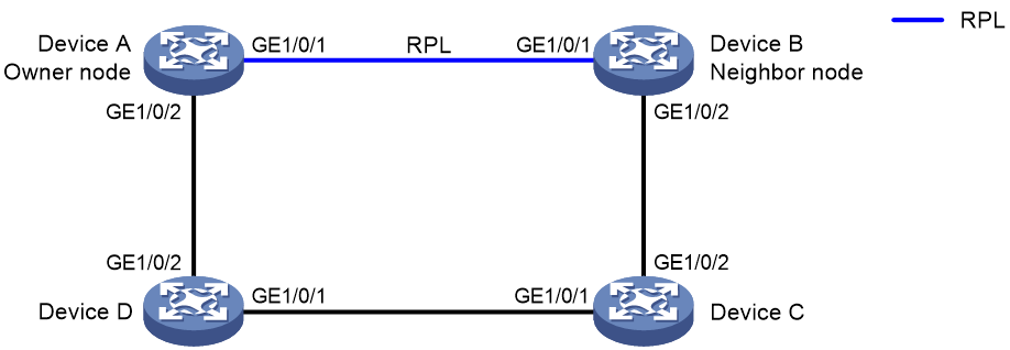
As shown in Figure 12, perform the following tasks to eliminate loops on the network:
· Configure the ring as ERPS ring 1.
· Configure VLAN 100 as the control VLAN for ERPS ring 1.
· Configure VLANs 1 to 30 as the protected VLANs for ERPS ring 1.
· Configure Device A as the owner node, GigabitEthernet 1/0/1 as ERPS ring member port 0 and the RPL port, and GigabitEthernet 1/0/2 as ERPS ring member port 1.
· Configure Device C and Device D as normal nodes, GigabitEthernet 1/0/1 as ERPS ring member port 0, and GigabitEthernet 1/0/2 as ERPS ring member port 1.
Configuration procedure
1. Configure Device A.
# Create VLANs 1 to 30, map these VLANs to MSTI 1, and activate the MST region configuration.
<DeviceA> system-view
[DeviceA] vlan 1 to 30
[DeviceA] stp region-configuration
[DeviceA-mst-region] instance 1 vlan 1 to 30
[DeviceA-mst-region] active region-configuration
[DeviceA-mst-region] quit
# Disable the spanning tree feature on the port.
[DeviceA] interface gigabitethernet 1/0/1
[DeviceA-GigabitEthernet1/0/1] undo stp enable
# Configure the port as a trunk port and assign it to VLANs 1 to 30.
[DeviceA-GigabitEthernet1/0/1] port link-type trunk
[DeviceA-GigabitEthernet1/0/1] port trunk permit vlan 1 to 30
[DeviceA-GigabitEthernet1/0/1] quit
# Configure GigabitEthernet 1/0/2 in the same way GigabitEthernet 1/0/1 is configured.
[DeviceA] interface gigabitethernet 1/0/2
[DeviceA-GigabitEthernet1/0/2] undo stp enable
[DeviceA-GigabitEthernet1/0/2] port link-type trunk
[DeviceA-GigabitEthernet1/0/2] port trunk permit vlan 1 to 30
[DeviceA-GigabitEthernet1/0/2] quit
# Create ERPS ring 1.
[DeviceA] erps ring 1
# Configure ERPS ring member ports.
[DeviceA-erps-ring1] port0 interface gigabitethernet 1/0/1
[DeviceA-erps-ring1] port1 interface gigabitethernet 1/0/2
# Enable R-APS packets to carry ring ID in the destination MAC address.
[DeviceA-erps-ring1] r-aps ring-mac
# Create ERPS instance 1.
[DeviceA-erps-ring1] instance 1
# Configure the node role.
[DeviceA-erps-ring1-inst1] node-role owner rpl port0
# Configure the control VLAN.
[DeviceA-erps-ring1-inst1] control-vlan 100
# Configure the protected VLANs.
[DeviceA-erps-ring1-inst1] protected-vlan reference-instance 1
# Enable ERPS for instance 1.
[DeviceA-erps-ring1-inst1] instance enable
[DeviceA-erps-ring1-inst1] quit
[DeviceA-erps-ring1] quit
# Enable CFD, and create a level-5 MD named MD_A.
[DeviceA] cfd enable
[DeviceA] cfd md MD_A level 5
# Create Ethernet service instance 1, in which the MA is identified by a VLAN and serves VLAN 1.
[DeviceA] cfd service-instance 1 ma-id vlan-based md MD_A vlan 1
# Configure a MEP list in Ethernet service instance 1, create outward-facing MEP 1001 in Ethernet service instance 1, and enable CCM sending on GigabitEthernet 1/0/1.
[DeviceA] cfd meplist 1001 1002 service-instance 1
[DeviceA] interface gigabitethernet 1/0/1
[DeviceA-GigabitEthernet1/0/1] cfd mep 1001 service-instance 1 outbound
[DeviceA-GigabitEthernet1/0/1] cfd cc service-instance 1 mep 1001 enable
[DeviceA-GigabitEthernet1/0/1] quit
# Create Ethernet service instance 2, in which the MA is identified by a VLAN and serves VLAN 2.
[DeviceA] cfd service-instance 2 ma-id vlan-based md MD_A vlan 2
# Configure a MEP list in Ethernet service instance 2, create outward-facing MEP 2001 in Ethernet service instance 1, and enable CCM sending on GigabitEthernet 1/0/2.
[DeviceA] cfd meplist 2001 2002 service-instance 2
[DeviceA] interface gigabitethernet 1/0/2
[DeviceA-GigabitEthernet1/0/2] cfd mep 2001 service-instance 2 outbound
[DeviceA-GigabitEthernet1/0/2] cfd cc service-instance 2 mep 2001 enable
[DeviceA-GigabitEthernet1/0/2] quit
# Create track entry 1 and associate it with the CC function of CFD for MEP 1001 in Ethernet service instance 1.
[DeviceA] track 1 cfd cc service-instance 1 mep 1001
# Associate GigabitEthernet 1/0/1 with track entry 1 and bring up the port.
[DeviceA] interface gigabitethernet 1/0/1
[DeviceA-GigabitEthernet1/0/1] port erps ring 1 instance 1 track 1
[DeviceA-GigabitEthernet1/0/1] undo shutdown
[DeviceA-GigabitEthernet1/0/1] quit
# Create track entry 2 and associate it with the CC function of CFD for MEP 2001 in Ethernet service instance 2.
[DeviceA] track 2 cfd cc service-instance 2 mep 2001
# Associate GigabitEthernet 1/0/2 with track entry 2 and bring up the port.
[DeviceA] interface gigabitethernet 1/0/2
[DeviceA-GigabitEthernet1/0/2] port erps ring 1 instance 1 track 2
[DeviceA-GigabitEthernet1/0/2] undo shutdown
[DeviceA-GigabitEthernet1/0/2] quit
# Enable ERPS.
[DeviceA] erps enable
2. Configure Device B.
# Create VLANs 1 to 30, map these VLANs to MSTI 1, and activate the MST region configuration.
<DeviceB> system-view
[DeviceB] vlan 1 to 30
[DeviceB] stp region-configuration
[DeviceB-mst-region] instance 1 vlan 1 to 30
[DeviceB-mst-region] active region-configuration
[DeviceB-mst-region] quit
# Disable the spanning tree feature on the port.
[DeviceB] interface gigabitethernet 1/0/1
[DeviceB-GigabitEthernet1/0/1] undo stp enable
[DeviceB-GigabitEthernet1/0/1] port link-type trunk
# Configure the port as a trunk port and assign it to VLANs 1 to 30.
[DeviceB-GigabitEthernet1/0/1] port trunk permit vlan 1 to 30
[DeviceB-GigabitEthernet1/0/1] quit
# Configure GigabitEthernet 1/0/2 in the same way GigabitEthernet 1/0/1 is configured.
[DeviceB] interface gigabitethernet 1/0/2
[DeviceB-GigabitEthernet1/0/2] undo stp enable
[DeviceB-GigabitEthernet1/0/2] port link-type trunk
[DeviceB-GigabitEthernet1/0/2] port trunk permit vlan 1 to 30
[DeviceB-GigabitEthernet1/0/2] quit
# Create ERPS ring 1.
[DeviceB] erps ring 1
# Configure ERPS ring member ports.
[DeviceB-erps-ring1] port0 interface gigabitethernet 1/0/1
[DeviceB-erps-ring1] port1 interface gigabitethernet 1/0/2
# Enable R-APS packets to carry ring ID in the destination MAC address.
[DeviceB-erps-ring1] r-aps ring-mac
# Create ERPS instance 1.
[DeviceB-erps-ring1] instance 1
# Configure the node role.
[DeviceB-erps-ring1-inst1] node-role neighbor rpl port0
# Configure the control VLAN.
[DeviceB-erps-ring1-inst1] control-vlan 100
# Configure the protected VLANs.
[DeviceB-erps-ring1-inst1] protected-vlan reference-instance 1
# Enable ERPS for instance 1.
[DeviceB-erps-ring1-inst1] instance enable
[DeviceB-erps-ring1-inst1] quit
[DeviceB-erps-ring1] quit
# Enable CFD, and create a level-5 MD named MD_A.
[DeviceB] cfd enable
[DeviceB] cfd md MD_A level 5
# Create Ethernet service instance 1, in which the MA is identified by a VLAN and serves VLAN 1.
[DeviceB] cfd service-instance 1 ma-id vlan-based md MD_A vlan 1
# Configure a MEP list in Ethernet service instance 1, create outward-facing MEP 1002 in Ethernet service instance 1, and enable CCM sending on GigabitEthernet 1/0/1.
[DeviceB] cfd meplist 1001 1002 service-instance 1
[DeviceB] interface gigabitethernet 1/0/1
[DeviceB-GigabitEthernet1/0/1] cfd mep 1002 service-instance 1 outbound
[DeviceB-GigabitEthernet1/0/1] cfd cc service-instance 1 mep 1002 enable
[DeviceB-GigabitEthernet1/0/1] quit
# Create Ethernet service instance 3, in which the MA is identified by a VLAN and serves VLAN 3.
[DeviceB] cfd service-instance 3 ma-id vlan-based md MD_A vlan 3
# Configure a MEP list in Ethernet service instance 3, create outward-facing MEP 3002 in Ethernet service instance 1, and enable CCM sending on GigabitEthernet 1/0/2.
[DeviceB] cfd meplist 3001 3002 service-instance 3
[DeviceB] interface gigabitethernet 1/0/2
[DeviceB-GigabitEthernet1/0/2] cfd mep 3002 service-instance 3 outbound
[DeviceB-GigabitEthernet1/0/2] cfd cc service-instance 3 mep 3002 enable
[DeviceB-GigabitEthernet1/0/2] quit
# Create track entry 1 and associate it with the CC function of CFD for MEP 1002 in Ethernet service instance 1.
[DeviceB] track 1 cfd cc service-instance 1 mep 1002
# Associate GigabitEthernet 1/0/1 with track entry 1 and bring up the port.
[DeviceB] interface gigabitethernet 1/0/1
[DeviceB-GigabitEthernet1/0/1] port erps ring 1 instance 1 track 1
[DeviceB-GigabitEthernet1/0/1] undo shutdown
[DeviceB-GigabitEthernet1/0/1] quit
# Create track entry 3 and associate it with the CC function of CFD for MEP 3002 in Ethernet service instance 3.
[DeviceB] track 3 cfd cc service-instance 3 mep 3002
# Associate GigabitEthernet 1/0/2 with track entry 3 and bring up the port.
[DeviceB] interface gigabitethernet 1/0/2
[DeviceB-GigabitEthernet1/0/2] port erps ring 1 instance 1 track 2
[DeviceB-GigabitEthernet1/0/2] undo shutdown
[DeviceB-GigabitEthernet1/0/2] quit
# Enable ERPS.
[DeviceB] erps enable
3. Configure Device C.
# Create VLANs 1 to 30, map these VLANs to MSTI 1, and activate the MST region configuration.
<DeviceC> system-view
[DeviceC] vlan 1 to 30
[DeviceC] stp region-configuration
[DeviceC-mst-region] instance 1 vlan 1 to 30
[DeviceC-mst-region] active region-configuration
[DeviceC-mst-region] quit
# Disable the spanning tree feature on the port.
[DeviceC] interface gigabitethernet 1/0/1
[DeviceC-GigabitEthernet1/0/1] undo stp enable
# Configure the port as a trunk port and assign it to VLANs 1 to 30.
[DeviceC-GigabitEthernet1/0/1] port link-type trunk
[DeviceC-GigabitEthernet1/0/1] port trunk permit vlan 1 to 30
[DeviceC-GigabitEthernet1/0/1] quit
# Configure GigabitEthernet 1/0/2 in the same way GigabitEthernet 1/0/1 is configured.
[DeviceC] interface gigabitethernet 1/0/2
[DeviceC-GigabitEthernet1/0/2] undo stp enable
[DeviceC-GigabitEthernet1/0/2] port link-type trunk
[DeviceC-GigabitEthernet1/0/2] port trunk permit vlan 1 to 30
[DeviceC-GigabitEthernet1/0/2] quit
# Create ERPS ring 1.
[DeviceC] erps ring 1
# Configure ERPS ring member ports.
[DeviceC-erps-ring1] port0 interface gigabitethernet 1/0/1
[DeviceC-erps-ring1] port1 interface gigabitethernet 1/0/2
# Enable R-APS packets to carry ring ID in the destination MAC address.
[DeviceC-erps-ring1] r-aps ring-mac
# Create ERPS instance 1.
[DeviceC-erps-ring1] instance 1
# Configure the control VLAN.
[DeviceC-erps-ring1-inst1] control-vlan 100
# Configure the protected VLANs.
[DeviceC-erps-ring1-inst1] protected-vlan reference-instance 1
# Enable ERPS for instance 1.
[DeviceC-erps-ring1-inst1] instance enable
[DeviceC-erps-ring1-inst1] quit
[DeviceC-erps-ring1] quit
# Enable CFD, and create a level-5 MD named MD_A.
[DeviceC] cfd enable
[DeviceC] cfd md MD_A level 5
# Create Ethernet service instance 3, in which the MA is identified by a VLAN and serves VLAN 3.
[DeviceC] cfd service-instance 3 ma-id vlan-based md MD_A vlan 3
# Configure a MEP list in Ethernet service instance 3, create outward-facing MEP 3001 in Ethernet service instance 3, and enable CCM sending on GigabitEthernet 1/0/1.
[DeviceC] cfd meplist 3001 3002 service-instance 3
[DeviceC] interface gigabitethernet 1/0/1
[DeviceC-GigabitEthernet1/0/1] cfd mep 3001 service-instance 3 outbound
[DeviceC-GigabitEthernet1/0/1] cfd cc service-instance 3 mep 3001 enable
[DeviceC-GigabitEthernet1/0/1] quit
# Create Ethernet service instance 4, in which the MA is identified by a VLAN and serves VLAN 4.
[DeviceC] cfd service-instance 4 ma-id vlan-based md MD_A vlan 4
# Configure a MEP list in Ethernet service instance 4, create outward-facing MEP 4001 in Ethernet service instance 4, and enable CCM sending on GigabitEthernet 1/0/2.
[DeviceC] cfd meplist 4001 4002 service-instance 4
[DeviceC] interface gigabitethernet 1/0/2
[DeviceC-GigabitEthernet1/0/2] cfd mep 4001 service-instance 4 outbound
[DeviceC-GigabitEthernet1/0/2] cfd cc service-instance 4 mep 4001 enable
[DeviceC-GigabitEthernet1/0/2] quit
# Create track entry 1 and associate it with the CC function of CFD for MEP 3001 in Ethernet service instance 3.
[DeviceC] track 1 cfd cc service-instance 3 mep 3001
# Associate GigabitEthernet 1/0/2 with track entry 1 and bring up the port.
[DeviceC] interface gigabitethernet 1/0/2
[DeviceC-GigabitEthernet1/0/2] port erps ring 1 instance 1 track 1
[DeviceC-GigabitEthernet1/0/2] undo shutdown
[DeviceC-GigabitEthernet1/0/2] quit
# Create track entry 2 and associate it with the CC function of CFD for MEP 4001 in Ethernet service instance 4.
[DeviceC] track 2 cfd cc service-instance 4 mep 4001
# Associate GigabitEthernet 1/0/1 with track entry 3 and bring up the port.
[DeviceC] interface gigabitethernet 1/0/1
[DeviceC-GigabitEthernet1/0/1] port erps ring 1 instance 1 track 2
[DeviceC-GigabitEthernet1/0/1] undo shutdown
[DeviceC-GigabitEthernet1/0/1] quit
# Enable ERPS.
[DeviceC] erps enable
4. Configure Device D.
# Create VLANs 1 to 30, map these VLANs to MSTI 1, and activate the MST region configuration.
<DeviceD> system-view
[DeviceD] vlan 1 to 30
[DeviceD] stp region-configuration
[DeviceD-mst-region] instance 1 vlan 1 to 30
[DeviceD-mst-region] active region-configuration
[DeviceD-mst-region] quit
# Disable the spanning tree feature on the port.
[DeviceD] interface gigabitethernet 1/0/1
[DeviceD-GigabitEthernet1/0/1] undo stp enable
# Configure the port as a trunk port and assign it to VLANs 1 to 30.
[DeviceD-GigabitEthernet1/0/1] port link-type trunk
[DeviceD-GigabitEthernet1/0/1] port trunk permit vlan 1 to 30
[DeviceD-GigabitEthernet1/0/1] quit
# Configure GigabitEthernet 1/0/2 in the same way GigabitEthernet 1/0/1 is configured.
[DeviceD] interface gigabitethernet 1/0/2
[DeviceD-GigabitEthernet1/0/2] undo stp enable
[DeviceD-GigabitEthernet1/0/2] port link-type trunk
[DeviceD-GigabitEthernet1/0/2] port trunk permit vlan 1 to 30
[DeviceD-GigabitEthernet1/0/2] quit
# Create ERPS ring 1.
[DeviceD] erps ring 1
# Configure ERPS ring member ports.
[DeviceD-erps-ring1] port0 interface gigabitethernet 1/0/1
[DeviceD-erps-ring1] port1 interface gigabitethernet 1/0/2
# Enable R-APS packets to carry ring ID in the destination MAC address.
[DeviceD-erps-ring1] r-aps ring-mac
# Create ERPS instance 1.
[DeviceD-erps-ring1] instance 1
# Configure the control VLAN.
[DeviceD-erps-ring1-inst1] control-vlan 100
# Configure the protected VLANs.
[DeviceD-erps-ring1-inst1] protected-vlan reference-instance 1
# Enable ERPS for instance 1.
[DeviceD-erps-ring1-inst1] instance enable
[DeviceD-erps-ring1-inst1] quit
[DeviceD-erps-ring1] quit
# Enable CFD, and create a level-5 MD named MD_A.
[DeviceD] cfd enable
[DeviceD] cfd md MD_A level 5
# Create Ethernet service instance 2, in which the MA is identified by a VLAN and serves VLAN 2.
[DeviceD] cfd service-instance 2 ma-id vlan-based md MD_A vlan 2
# Configure a MEP list in Ethernet service instance 2, create outward-facing MEP 2002 in Ethernet service instance 2, and enable CCM sending on GigabitEthernet 1/0/2.
[DeviceD] cfd meplist 2001 2002 service-instance 2
[DeviceD] interface gigabitethernet 1/0/2
[DeviceD-GigabitEthernet1/0/2] cfd mep 2002 service-instance 2 outbound
[DeviceD-GigabitEthernet1/0/2] cfd cc service-instance 2 mep 2002 enable
[DeviceD-GigabitEthernet1/0/2] quit
# Create Ethernet service instance 4, in which the MA is identified by a VLAN and serves VLAN 4.
[DeviceD] cfd service-instance 4 ma-id vlan-based md MD_A vlan 4
# Configure a MEP list in Ethernet service instance 4, create outward-facing MEP 4002 in Ethernet service instance 4, and enable CCM sending on GigabitEthernet 1/0/1.
[DeviceD] cfd meplist 4001 4002 service-instance 4
[DeviceD] interface gigabitethernet 1/0/1
[DeviceD-GigabitEthernet1/0/1] cfd mep 4002 service-instance 4 outbound
[DeviceD-GigabitEthernet1/0/1] cfd cc service-instance 4 mep 4002 enable
[DeviceD-GigabitEthernet1/0/1] quit
# Create track entry 1 and associate it with the CC function of CFD for MEP 2002 in Ethernet service instance 2.
[DeviceD] track 1 cfd cc service-instance 2 mep 2002
# Associate GigabitEthernet 1/0/2 with track entry 1 and bring up the port.
[DeviceD] interface gigabitethernet 1/0/2
[DeviceD-GigabitEthernet1/0/2] port erps ring 1 instance 1 track 1
[DeviceD-GigabitEthernet1/0/2] undo shutdown
[DeviceD-GigabitEthernet1/0/2] quit
# Create track entry 2 and associate it with the CC function of CFD for MEP 4002 in Ethernet service instance 4.
[DeviceD] track 2 cfd cc service-instance 4 mep 4002
# Associate GigabitEthernet 1/0/1 with track entry 2 and bring up the port.
[DeviceD] interface gigabitethernet 1/0/1
[DeviceD-GigabitEthernet1/0/1] port erps ring 1 instance 1 track 2
[DeviceD-GigabitEthernet1/0/1] undo shutdown
[DeviceD-GigabitEthernet1/0/1] quit
# Enable ERPS.
[DeviceD] erps enable
Verifying the configuration
# Display information about ERPS instance 1 for Device A.
[DeviceA] display erps detail ring 1
Ring ID : 1
Port0 : GigabitEthernet1/0/1
Port1 : GigabitEthernet1/0/2
Subring : No
Default MAC : No
Instance ID : 1
Node role : Owner
Node state : Idle
Connect(ring/instance): -
Control VLAN : 100
Protected VLAN : Reference-instance 1
Guard timer : 500 ms
Hold-off timer : 0 ms
WTR timer : 5 min
Revertive operation : Revertive
Enable status : Yes, Active status : Yes
R-APS level : 7
Port PortRole PortStatus
----------------------------------------------------------------------------
Port0 RPL Block
Port1 Non-RPL Up
The output shows the following information:
· Device A is the owner node.
· The ERPS ring is in idle state.
· The RPL port is blocked.
· The non-RPL port is unblocked.
One-subring configuration example
Network requirements
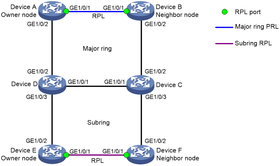
As shown in Figure 13, perform the following tasks to eliminate loops on the network:
· Configure VLAN 100 and VLAN 200 as the control VLANs for the major ring and the subring, respectively.
· Configure VLANs 1 to 30 as the protected VLANs for the major ring and subring.
· Configure Device A as the owner node for the major ring, GigabitEthernet 1/0/1 as ERPS ring member port 0 and the RPL port, and GigabitEthernet 1/0/2 as ERPS ring member port 1.
· Configure Device B as the neighbor node for the major ring, GigabitEthernet 1/0/1 as ERPS ring member port 0 and the RPL port, and GigabitEthernet 1/0/2 as ERPS ring member port 1.
· Configure Devices C and D as interconnection nodes, GigabitEthernet 1/0/1 as ERPS ring member port 0, GigabitEthernet 1/0/2 as ERPS ring member port 1, and GigabitEthernet 1/0/3 as the interconnection port.
· Configure Device E as the owner node for the subring, GigabitEthernet 1/0/1 as ERPS ring member port 0 and the RPL port, and GigabitEthernet 1/0/2 as ERPS ring member port 1.
· Configure Device F as the neighbor node for the subring, GigabitEthernet 1/0/1 as ERPS ring member port 0 and the RPL port, and GigabitEthernet 1/0/2 as ERPS ring member port 1.
Configuration procedure
1. Configure Device A.
# Create VLANs 1 to 30, map these VLANs to MSTI 1, and activate the MST region configuration.
<DeviceA> system-view
[DeviceA] vlan 1 to 30
[DeviceA] stp region-configuration
[DeviceA-mst-region] instance 1 vlan 1 to 30
[DeviceA-mst-region] active region-configuration
[DeviceA-mst-region] quit
# Disable the spanning tree feature on the port.
[DeviceA] interface gigabitethernet 1/0/1
[DeviceA-GigabitEthernet1/0/1] undo stp enable
# Configure the port as a trunk port and assign it to VLANs 1 to 30.
[DeviceA-GigabitEthernet1/0/1] port link-type trunk
[DeviceA-GigabitEthernet1/0/1] port trunk permit vlan 1 to 30
[DeviceA-GigabitEthernet1/0/1] quit
# Configure GigabitEthernet 1/0/2 in the same way GigabitEthernet 1/0/1 is configured.
[DeviceA] interface gigabitethernet 1/0/2
[DeviceA-GigabitEthernet1/0/2] undo stp enable
[DeviceA-GigabitEthernet1/0/2] port link-type trunk
[DeviceA-GigabitEthernet1/0/2] port trunk permit vlan 1 to 30
[DeviceA-GigabitEthernet1/0/2] quit
# Create ERPS ring 1.
[DeviceA] erps ring 1
# Configure ERPS ring member ports.
[DeviceA-erps-ring1] port0 interface gigabitethernet 1/0/1
[DeviceA-erps-ring1] port1 interface gigabitethernet 1/0/2
# Create ERPS instance 1.
[DeviceA-erps-ring1] instance 1
# Configure the node role.
[DeviceA-erps-ring1-inst1] node-role owner rpl port0
# Configure the control VLAN.
[DeviceA-erps-ring1-inst1] control-vlan 100
# Configure the protected VLANs.
[DeviceA-erps-ring1-inst1] protected-vlan reference-instance 1
# Enable ERPS for instance 1.
[DeviceA-erps-ring1-inst1] instance enable
[DeviceA-erps-ring1-inst1] quit
[DeviceA-erps-ring1] quit
# Enable CFD, and create a level-5 MD named MD_A.
[DeviceA] cfd enable
[DeviceA] cfd md MD_A level 5
# Create Ethernet service instance 1, in which the MA is identified by a VLAN and serves VLAN 1.
[DeviceA] cfd service-instance 1 ma-id vlan-based md MD_A vlan 1
# Configure a MEP list in Ethernet service instance 1, create outward-facing MEP 1001 in Ethernet service instance 1, and enable CCM sending on GigabitEthernet 1/0/1.
[DeviceA] cfd meplist 1001 1002 service-instance 1
[DeviceA] interface gigabitethernet 1/0/1
[DeviceA-GigabitEthernet1/0/1] cfd mep 1001 service-instance 1 outbound
[DeviceA-GigabitEthernet1/0/1] cfd cc service-instance 1 mep 1001 enable
[DeviceA-GigabitEthernet1/0/1] quit
# Create Ethernet service instance 2, in which the MA is identified by a VLAN and serves VLAN 2.
[DeviceA] cfd service-instance 2 ma-id vlan-based md MD_A vlan 2
# Configure a MEP list in Ethernet service instance 2, create outward-facing MEP 2001 in Ethernet service instance 1, and enable CCM sending on GigabitEthernet 1/0/2.
[DeviceA] cfd meplist 2001 2002 service-instance 2
[DeviceA] interface gigabitethernet 1/0/2
[DeviceA-GigabitEthernet1/0/2] cfd mep 2001 service-instance 2 outbound
[DeviceA-GigabitEthernet1/0/2] cfd cc service-instance 2 mep 2001 enable
[DeviceA-GigabitEthernet1/0/2] quit
# Create track entry 1 and associate it with the CC function of CFD for MEP 1001 in Ethernet service instance 1.
[DeviceA] track 1 cfd cc service-instance 1 mep 1001
# Associate GigabitEthernet 1/0/1 with track entry 1 and bring up the port.
[DeviceA] interface gigabitethernet 1/0/1
[DeviceA-GigabitEthernet1/0/1] port erps ring 1 instance 1 track 1
[DeviceA-GigabitEthernet1/0/1] undo shutdown
[DeviceA-GigabitEthernet1/0/1] quit
# Create track entry 2 and associate it with the CC function of CFD for MEP 2001 in Ethernet service instance 2.
[DeviceA] track 2 cfd cc service-instance 2 mep 2001
# Associate GigabitEthernet 1/0/2 with track entry 2 and bring up the port.
[DeviceA] interface gigabitethernet 1/0/2
[DeviceA-GigabitEthernet1/0/2] port erps ring 1 instance 1 track 2
[DeviceA-GigabitEthernet1/0/2] undo shutdown
[DeviceA-GigabitEthernet1/0/2] quit
# Enable ERPS.
[DeviceA] erps enable
2. Configure Device B.
# Create VLANs 1 to 30, map these VLANs to MSTI 1, and activate the MST region configuration.
<DeviceB> system-view
[DeviceB] vlan 1 to 30
[DeviceB] stp region-configuration
[DeviceB-mst-region] instance 1 vlan 1 to 30
[DeviceB-mst-region] active region-configuration
[DeviceB-mst-region] quit
# Disable the spanning tree feature on the port.
[DeviceB] interface gigabitethernet 1/0/1
[DeviceB-GigabitEthernet1/0/1] undo stp enable
# Configure the port as a trunk port and assign it to VLANs 1 to 30.
[DeviceB-GigabitEthernet1/0/1] port link-type trunk
[DeviceB-GigabitEthernet1/0/1] port trunk permit vlan 1 to 30
[DeviceB-GigabitEthernet1/0/1] quit
# Configure GigabitEthernet 1/0/2 in the same way GigabitEthernet 1/0/1 is configured.
[DeviceB] interface gigabitethernet 1/0/2
[DeviceB-GigabitEthernet1/0/2] undo stp enable
[DeviceB-GigabitEthernet1/0/2] port link-type trunk
[DeviceB-GigabitEthernet1/0/2] port trunk permit vlan 1 to 30
[DeviceB-GigabitEthernet1/0/2] quit
# Create ERPS ring 1.
[DeviceB] erps ring 1
# Configure ERPS ring member ports.
[DeviceB-erps-ring1] port0 interface gigabitethernet 1/0/1
[DeviceB-erps-ring1] port1 interface gigabitethernet 1/0/2
# Create ERPS instance 1.
[DeviceB-erps-ring1] instance 1
# Configure the node role.
[DeviceB-erps-ring1-inst1] node-role neighbor rpl port0
# Configure the control VLAN.
[DeviceB-erps-ring1-inst1] control-vlan 100
# Configure the protected VLANs.
[DeviceB-erps-ring1-inst1] protected-vlan reference-instance 1
# Enable ERPS for instance 1.
[DeviceB-erps-ring1-inst1] instance enable
[DeviceB-erps-ring1-inst1] quit
[DeviceB-erps-ring1] quit
# Enable CFD, and create a level-5 MD named MD_A.
[DeviceB] cfd enable
[DeviceB] cfd md MD_A level 5
# Create Ethernet service instance 1, in which the MA is identified by a VLAN and serves VLAN 1.
[DeviceB] cfd service-instance 1 ma-id vlan-based md MD_A vlan 1
# Configure a MEP list in Ethernet service instance 1, create outward-facing MEP 1002 in Ethernet service instance 1, and enable CCM sending on GigabitEthernet 1/0/1.
[DeviceB] cfd meplist 1001 1002 service-instance 1
[DeviceB] interface gigabitethernet 1/0/1
[DeviceB-GigabitEthernet1/0/1] cfd mep 1002 service-instance 1 outbound
[DeviceB-GigabitEthernet1/0/1] cfd cc service-instance 1 mep 1002 enable
[DeviceB-GigabitEthernet1/0/1] quit
# Create Ethernet service instance 3, in which the MA is identified by a VLAN and serves VLAN 3.
[DeviceB] cfd service-instance 3 ma-id vlan-based md MD_A vlan 3
# Configure a MEP list in Ethernet service instance 3, create outward-facing MEP 3002 in Ethernet service instance 2, and enable CCM sending on GigabitEthernet 1/0/2.
[DeviceB] cfd meplist 3001 3002 service-instance 3
[DeviceB] interface gigabitethernet 1/0/2
[DeviceB-GigabitEthernet1/0/2] cfd mep 3002 service-instance 3 outbound
[DeviceB-GigabitEthernet1/0/2] cfd cc service-instance 3 mep 3002 enable
[DeviceB-GigabitEthernet1/0/2] quit
# Create track entry 1 and associate it with the CC function of CFD for MEP 1002 in Ethernet service instance 1.
[DeviceB] track 1 cfd cc service-instance 1 mep 1002
# Associate GigabitEthernet 1/0/1 with track entry 1 and bring up the port.
[DeviceB] interface gigabitethernet 1/0/1
[DeviceB-GigabitEthernet1/0/1] port erps ring 1 instance 1 track 1
[DeviceB-GigabitEthernet1/0/1] undo shutdown
[DeviceB-GigabitEthernet1/0/1] quit
# Create track entry 3 and associate it with the CC function of CFD for MEP 3002 in Ethernet service instance 3.
[DeviceB] track 3 cfd cc service-instance 3 mep 3002
# Associate GigabitEthernet 1/0/2 with track entry 3 and bring up the port.
[DeviceB] interface gigabitethernet 1/0/2
[DeviceB-GigabitEthernet1/0/2] port erps ring 1 instance 1 track 2
[DeviceB-GigabitEthernet1/0/2] undo shutdown
[DeviceB-GigabitEthernet1/0/2] quit
# Enable ERPS.
[DeviceB] erps enable
3. Configure Device C.
# Create VLANs 1 to 30, map these VLANs to MSTI 1, and activate the MST region configuration.
<DeviceC> system-view
[DeviceC] vlan 1 to 30
[DeviceC] stp region-configuration
[DeviceC-mst-region] instance 1 vlan 1 to 30
[DeviceC-mst-region] active region-configuration
[DeviceC-mst-region] quit
# Disable the spanning tree feature on the port.
[DeviceC] interface gigabitethernet 1/0/1
[DeviceC-GigabitEthernet1/0/1] undo stp enable
# Configure the port as a trunk port and assign it to VLANs 1 to 30.
[DeviceC-GigabitEthernet1/0/1] port link-type trunk
[DeviceC-GigabitEthernet1/0/1] port trunk permit vlan 1 to 30
[DeviceC-GigabitEthernet1/0/1] quit
# Configure GigabitEthernet 1/0/2 in the same way GigabitEthernet 1/0/1 is configured.
[DeviceC] interface gigabitethernet 1/0/2
[DeviceC-GigabitEthernet1/0/2] undo stp enable
[DeviceC-GigabitEthernet1/0/2] port link-type trunk
[DeviceC-GigabitEthernet1/0/2] port trunk permit vlan 1 to 30
[DeviceC-GigabitEthernet1/0/2] quit
# Configure GigabitEthernet 1/0/3 in the same way GigabitEthernet 1/0/1 is configured.
[DeviceC] interface gigabitethernet 1/0/3
[DeviceC-GigabitEthernet1/0/3] undo stp enable
[DeviceC-GigabitEthernet1/0/3] port link-type trunk
[DeviceC-GigabitEthernet1/0/3] port trunk permit vlan 1 to 30
[DeviceC-GigabitEthernet1/0/3] quit
# Create ERPS ring 1.
[DeviceC] erps ring 1
# Configure ERPS ring member ports.
[DeviceC-erps-ring1] port0 interface gigabitethernet 1/0/1
[DeviceC-erps-ring1] port1 interface gigabitethernet 1/0/2
# Create ERPS instance 1.
[DeviceC-erps-ring1] instance 1
# Configure the control VLAN.
[DeviceC-erps-ring1-inst1] control-vlan 100
# Configure the protected VLANs.
[DeviceC-erps-ring1-inst1] protected-vlan reference-instance 1
# Enable ERPS for instance 1.
[DeviceC-erps-ring1-inst1] instance enable
[DeviceC-erps-ring1-inst1] quit
[DeviceC-erps-ring1] quit
# Enable CFD, and create a level-5 MD named MD_A.
[DeviceC] cfd enable
[DeviceC] cfd md MD_A level 5
# Create Ethernet service instance 3, in which the MA is identified by a VLAN and serves VLAN 3.
[DeviceC] cfd service-instance 3 ma-id vlan-based md MD_A vlan 3
# Configure a MEP list in Ethernet service instance 3, create outward-facing MEP 3001 in Ethernet service instance 3, and enable CCM sending on GigabitEthernet 1/0/2.
[DeviceC] cfd meplist 3001 3002 service-instance 3
[DeviceC] interface gigabitethernet 1/0/2
[DeviceC-GigabitEthernet1/0/2] cfd mep 3001 service-instance 3 outbound
[DeviceC-GigabitEthernet1/0/2] cfd cc service-instance 3 mep 3001 enable
[DeviceC-GigabitEthernet1/0/2] quit
# Create Ethernet service instance 4, in which the MA is identified by a VLAN and serves VLAN 4.
[DeviceC] cfd service-instance 4 ma-id vlan-based md MD_A vlan 4
# Configure a MEP list in Ethernet service instance 4, create outward-facing MEP 4001 in Ethernet service instance 4, and enable CCM sending on GigabitEthernet 1/0/1.
[DeviceC] cfd meplist 4001 4002 service-instance 4
[DeviceC] interface gigabitethernet 1/0/1
[DeviceC-GigabitEthernet1/0/1] cfd mep 4001 service-instance 4 outbound
[DeviceC-GigabitEthernet1/0/1] cfd cc service-instance 4 mep 4001 enable
[DeviceC-GigabitEthernet1/0/1] quit
# Create track entry 1 and associate it with the CC function of CFD for MEP 3001 in Ethernet service instance 3.
[DeviceC] track 1 cfd cc service-instance 3 mep 3001
# Associate GigabitEthernet 1/0/2 with track entry 1 and bring up the port.
[DeviceC] interface gigabitethernet 1/0/2
[DeviceC-GigabitEthernet1/0/2] port erps ring 1 instance 1 track 1
[DeviceC-GigabitEthernet1/0/2] undo shutdown
[DeviceC-GigabitEthernet1/0/2] quit
# Create track entry 2 and associate it with the CC function of CFD for MEP 4001 in Ethernet service instance 4.
[DeviceC] track 2 cfd cc service-instance 4 mep 4001
# Associate GigabitEthernet 1/0/1 with track entry 2 and bring up the port.
[DeviceC] interface gigabitethernet 1/0/1
[DeviceC-GigabitEthernet1/0/1] port erps ring 1 instance 1 track 2
[DeviceC-GigabitEthernet1/0/1] undo shutdown
[DeviceC-GigabitEthernet1/0/1] quit
# Create ERPS ring 2.
[DeviceC] erps ring 2
# Configure ERPS ring member ports.
[DeviceC-erps-ring2] port0 interface gigabitethernet 1/0/3
# Configure ERPS ring 2 as the subring.
[DeviceC-erps-ring2] ring-type sub-ring
# Create ERPS instance 1.
[DeviceC-erps-ring2] instance 1
# Configure the node role.
[DeviceC-erps-ring2-inst1] node-role interconnection port0
# Configure the control VLAN.
[DeviceC-erps-ring2-inst1] control-vlan 110
# Configure the protected VLANs.
[DeviceC-erps-ring2-inst1] protected-vlan reference-instance 1
# Enable ERPS for instance 1.
[DeviceC-erps-ring2-inst1] instance enable
[DeviceC-erps-ring2-inst1] quit
[DeviceC-erps-ring2] quit
# Create Ethernet service instance 5, in which the MA is identified by a VLAN and serves VLAN 5.
[DeviceC] cfd service-instance 5 ma-id vlan-based md MD_A vlan 5
# Configure a MEP list in Ethernet service instance 5, create outward-facing MEP 5001 in Ethernet service instance 3, and enable CCM sending on GigabitEthernet 1/0/3.
[DeviceC] cfd meplist 5001 5002 service-instance 5
[DeviceC] interface gigabitethernet 1/0/3
[DeviceC-GigabitEthernet1/0/3] cfd mep 5001 service-instance 5 outbound
[DeviceC-GigabitEthernet1/0/3] cfd cc service-instance 5 mep 5001 enable
[DeviceC-GigabitEthernet1/0/3] quit
# Create track entry 1 and associate it with the CC function of CFD for MEP 5001 in Ethernet service instance 3.
[DeviceC] track 1 cfd cc service-instance 5 mep 5001
# Associate GigabitEthernet 1/0/3 with track entry 1 and bring up the port.
[DeviceC] interface gigabitethernet 1/0/3
[DeviceC-GigabitEthernet1/0/3] port erps ring 2 instance 1 track 1
[DeviceC-GigabitEthernet1/0/3] undo shutdown
[DeviceC-GigabitEthernet1/0/3] quit
# Enable ERPS.
[DeviceC] erps enable
4. Configure Device D.
# Create VLANs 1 to 30, map these VLANs to MSTI 1, and activate the MST region configuration.
<DeviceD> system-view
[DeviceD] vlan 1 to 30
[DeviceD] stp region-configuration
[DeviceD-mst-region] instance 1 vlan 1 to 30
[DeviceD-mst-region] active region-configuration
[DeviceD-mst-region] quit
# Disable the spanning tree feature on the port.
[DeviceD] interface gigabitethernet 1/0/1
[DeviceD-GigabitEthernet1/0/1] undo stp enable
# Configure the port as a trunk port and assign it to VLANs 1 to 30.
[DeviceD-GigabitEthernet1/0/1] port link-type trunk
[DeviceD-GigabitEthernet1/0/1] port trunk permit vlan 1 to 30
[DeviceD-GigabitEthernet1/0/1] quit
# Configure GigabitEthernet 1/0/2 in the same way GigabitEthernet 1/0/1 is configured.
[DeviceD] interface gigabitethernet 1/0/2
[DeviceD-GigabitEthernet1/0/2] undo stp enable
[DeviceD-GigabitEthernet1/0/2] port link-type trunk
[DeviceD-GigabitEthernet1/0/2] port trunk permit vlan 1 to 30
[DeviceD-GigabitEthernet1/0/2] quit
# Configure GigabitEthernet 1/0/3 in the same way GigabitEthernet 1/0/1 is configured.
[DeviceD] interface gigabitethernet 1/0/3
[DeviceD-GigabitEthernet1/0/3] undo stp enable
[DeviceD-GigabitEthernet1/0/3] port link-type trunk
[DeviceD-GigabitEthernet1/0/3] port trunk permit vlan 1 to 30
[DeviceD-GigabitEthernet1/0/3] quit
# Create ERPS ring 1.
[DeviceD] erps ring 1
# Configure ERPS ring member ports.
[DeviceD-erps-ring1] port0 interface gigabitethernet 1/0/1
[DeviceD-erps-ring1] port1 interface gigabitethernet 1/0/2
# Create ERPS instance 1.
[DeviceD-erps-ring1] instance 1
# Configure the control VLAN.
[DeviceD-erps-ring1-inst1] control-vlan 100
# Configure the protected VLANs.
[DeviceD-erps-ring1-inst1] protected-vlan reference-instance 1
# Enable ERPS for instance 1.
[DeviceD-erps-ring1-inst1] instance enable
[DeviceD-erps-ring1-inst1] quit
[DeviceD-erps-ring1] quit
# Enable CFD, and create a level-5 MD named MD_A.
[DeviceD] cfd enable
[DeviceD] cfd md MD_A level 5
# Create Ethernet service instance 2, in which the MA is identified by a VLAN and serves VLAN 2.
[DeviceD] cfd service-instance 2 ma-id vlan-based md MD_A vlan 2
# Configure a MEP list in Ethernet service instance 2, create outward-facing MEP 2002 in Ethernet service instance 2, and enable CCM sending on GigabitEthernet 1/0/2.
[DeviceD] cfd meplist 2001 2002 service-instance 2
[DeviceD] interface gigabitethernet 1/0/2
[DeviceD-GigabitEthernet1/0/2] cfd mep 2002 service-instance 2 outbound
[DeviceD-GigabitEthernet1/0/2] cfd cc service-instance 2 mep 2002 enable
[DeviceD-GigabitEthernet1/0/2] quit
# Create Ethernet service instance 4, in which the MA is identified by a VLAN and serves VLAN 4.
[DeviceD] cfd service-instance 4 ma-id vlan-based md MD_A vlan 4
# Configure a MEP list in Ethernet service instance 4, create outward-facing MEP 4002 in Ethernet service instance 4, and enable CCM sending on GigabitEthernet 1/0/1.
[DeviceD] cfd meplist 4001 4002 service-instance 4
[DeviceD] interface gigabitethernet 1/0/1
[DeviceD-GigabitEthernet1/0/1] cfd mep 4002 service-instance 4 outbound
[DeviceD-GigabitEthernet1/0/1] cfd cc service-instance 4 mep 4002 enable
[DeviceD-GigabitEthernet1/0/1] quit
# Create track entry 1 and associate it with the CC function of CFD for MEP 2002 in Ethernet service instance 2.
[DeviceD] track 1 cfd cc service-instance 2 mep 2002
# Associate GigabitEthernet 1/0/2 with track entry 1 and bring up the port.
[DeviceD] interface gigabitethernet 1/0/2
[DeviceD-GigabitEthernet1/0/2] port erps ring 1 instance 1 track 1
[DeviceD-GigabitEthernet1/0/2] undo shutdown
[DeviceD-GigabitEthernet1/0/2] quit
# Create track entry 2 and associate it with the CC function of CFD for MEP 4002 in Ethernet service instance 4.
[DeviceD] track 2 cfd cc service-instance 4 mep 4002
# Associate GigabitEthernet 1/0/1 with track entry 2 and bring up the port.
[DeviceD] interface gigabitethernet 1/0/1
[DeviceD-GigabitEthernet1/0/1] port erps ring 1 instance 1 track 2
[DeviceD-GigabitEthernet1/0/1] undo shutdown
[DeviceD-GigabitEthernet1/0/1] quit
# Create ERPS ring 2.
[DeviceD] erps ring 2
# Configure ERPS ring member ports.
[DeviceD-erps-ring2] port0 interface gigabitethernet 1/0/3
# Configure ERPS ring 2 as the subring.
[DeviceD-erps-ring2] ring-type sub-ring
# Create ERPS instance 1.
[DeviceD-erps-ring2] instance 1
# Configure the node role.
[DeviceD-erps-ring2-inst1] node-role interconnection port0
# Configure the control VLAN.
[DeviceD-erps-ring2-inst1] control-vlan 110
# Configure the protected VLANs.
[DeviceD-erps-ring2-inst1] protected-vlan reference-instance 1
# Enable ERPS for instance 1.
[DeviceD-erps-ring2-inst1] instance enable
[DeviceD-erps-ring2-inst1] quit
[DeviceD-erps-ring2] quit
# Create Ethernet service instance 6, in which the MA is identified by a VLAN and serves VLAN 6.
[DeviceD] cfd service-instance 6 ma-id vlan-based md MD_A vlan 6
# Configure a MEP list in Ethernet service instance 6, create outward-facing MEP 6002 in Ethernet service instance 3, and enable CCM sending on GigabitEthernet 1/0/3.
[DeviceD] cfd meplist 6001 6002 service-instance 6
[DeviceD] interface gigabitethernet 1/0/3
[DeviceD-GigabitEthernet1/0/3] cfd mep 6002 service-instance 6 outbound
[DeviceD-GigabitEthernet1/0/3] cfd cc service-instance 6 mep 6002 enable
[DeviceD-GigabitEthernet1/0/3] quit
# Create track entry 3 and associate it with the CC function of CFD for MEP 6002 in Ethernet service instance 6.
[DeviceD] track 3 cfd cc service-instance 6 mep 6002
# Associate GigabitEthernet 1/0/3 with track entry 3 and bring up the port.
[DeviceD] interface gigabitethernet 1/0/3
[DeviceD-GigabitEthernet1/0/3] port erps ring 2 instance 1 track 3
[DeviceD-GigabitEthernet1/0/3] undo shutdown
[DeviceD-GigabitEthernet1/0/3] quit
# Enable ERPS.
[DeviceD] erps enable
5. Configure Device E.
# Create VLANs 1 to 30, map these VLANs to MSTI 1, and activate the MST region configuration.
<DeviceE> system-view
[DeviceE] vlan 1 to 30
[DeviceE] stp region-configuration
[DeviceE-mst-region] instance 1 vlan 1 to 30
[DeviceE-mst-region] active region-configuration
[DeviceE-mst-region] quit
# Disable the spanning tree feature on the port.
[DeviceE] interface gigabitethernet 1/0/1
[DeviceE-GigabitEthernet1/0/1] undo stp enable
# Configure the port as a trunk port and assign it to VLANs 1 to 30.
[DeviceE-GigabitEthernet1/0/1] port link-type trunk
[DeviceE-GigabitEthernet1/0/1] port trunk permit vlan 1 to 30
[DeviceE-GigabitEthernet1/0/1] quit
# Configure GigabitEthernet 1/0/2 in the same way GigabitEthernet 1/0/1 is configured.
[DeviceE] interface gigabitethernet 1/0/2
[DeviceE-GigabitEthernet1/0/2] undo stp enable
[DeviceE-GigabitEthernet1/0/2] port link-type trunk
[DeviceE-GigabitEthernet1/0/2] port trunk permit vlan 1 to 30
[DeviceE-GigabitEthernet1/0/2] quit
# Create ERPS ring 2.
[DeviceE] erps ring 2
# Configure ERPS ring member ports.
[DeviceE-erps-ring2] port0 interface gigabitethernet 1/0/1
[DeviceE-erps-ring2] port1 interface gigabitethernet 1/0/2
# Configure ERPS ring 2 as the subring.
[DeviceE-erps-ring2] ring-type sub-ring
# Create ERPS instance 1.
[DeviceE-erps-ring2] instance 1
# Configure the node role.
[DeviceE-erps-ring2] node-role owner rpl port0
# Configure the control VLAN.
[DeviceE-erps-ring2-inst1] control-vlan 110
# Configure the protected VLANs.
[DeviceE-erps-ring2-inst1] protected-vlan reference-instance 1
# Enable ERPS for instance 1.
[DeviceE-erps-ring2-inst1] instance enable
[DeviceE-erps-ring2-inst1] quit
[DeviceE-erps-ring2] quit
# Enable CFD, and create a level-5 MD named MD_A.
[DeviceE] cfd enable
[DeviceE] cfd md MD_A level 5
# Create Ethernet service instance 6, in which the MA is identified by a VLAN and serves VLAN 6.
[DeviceE] cfd service-instance 6 ma-id vlan-based md MD_A vlan 6
# Configure a MEP list in Ethernet service instance 6, create outward-facing MEP 6001 in Ethernet service instance 6, and enable CCM sending on GigabitEthernet 1/0/2.
[DeviceE] cfd meplist 6001 6002 service-instance 6
[DeviceE] interface gigabitethernet 1/0/2
[DeviceE-GigabitEthernet1/0/2] cfd mep 6001 service-instance 6 outbound
[DeviceE-GigabitEthernet1/0/2] cfd cc service-instance 6 mep 6001 enable
[DeviceE-GigabitEthernet1/0/2] quit
# Create Ethernet service instance 7, in which the MA is identified by a VLAN and serves VLAN 7.
[DeviceE] cfd service-instance 7 ma-id vlan-based md MD_A vlan 7
# Configure a MEP list in Ethernet service instance 7, create outward-facing MEP 7001 in Ethernet service instance 7, and enable CCM sending on GigabitEthernet 1/0/1.
[DeviceE] cfd meplist 7001 7002 service-instance 7
[DeviceE] interface gigabitethernet 1/0/1
[DeviceE-GigabitEthernet1/0/1] cfd mep 7001 service-instance 7 outbound
[DeviceE-GigabitEthernet1/0/1] cfd cc service-instance 7 mep 7001 enable
[DeviceE-GigabitEthernet1/0/1] quit
# Create track entry 1 and associate it with the CC function of CFD for MEP 6001 in Ethernet service instance 6.
[DeviceE] track 1 cfd cc service-instance 6 mep 6001
# Associate GigabitEthernet 1/0/2 with track entry 1 and bring up the port.
[DeviceE] interface gigabitethernet 1/0/2
[DeviceE-GigabitEthernet1/0/2] port erps ring 2 instance 1 track 1
[DeviceE-GigabitEthernet1/0/2] undo shutdown
[DeviceE-GigabitEthernet1/0/2] quit
# Create track entry 2 and associate it with the CC function of CFD for MEP 7001 in Ethernet service instance 7.
[DeviceE] track 2 cfd cc service-instance 7 mep 7001
# Associate GigabitEthernet 1/0/1 with track entry 2 and bring up the port.
[DeviceE] interface gigabitethernet 1/0/1
[DeviceE-GigabitEthernet1/0/1] port erps ring 2 instance 1 track 2
[DeviceE-GigabitEthernet1/0/1] undo shutdown
[DeviceE-GigabitEthernet1/0/1] quit
# Enable ERPS.
[DeviceE] erps enable
6. Configure Device F.
# Create VLANs 1 to 30, map these VLANs to MSTI 1, and activate the MST region configuration.
<DeviceF> system-view
[DeviceF] vlan 1 to 30
[DeviceF] stp region-configuration
[DeviceF-mst-region] instance 1 vlan 1 to 30
[DeviceF-mst-region] active region-configuration
[DeviceF-mst-region] quit
# Disable the spanning tree feature on the port.
[DeviceF] interface gigabitethernet 1/0/1
[DeviceF-GigabitEthernet1/0/1] undo stp enable
# Configure the port as a trunk port and assign it to VLANs 1 to 30.
[DeviceF-GigabitEthernet1/0/1] port link-type trunk
[DeviceF-GigabitEthernet1/0/1] port trunk permit vlan 1 to 30
[DeviceF-GigabitEthernet1/0/1] quit
# Configure GigabitEthernet 1/0/2 in the same way GigabitEthernet 1/0/1 is configured.
[DeviceF] interface gigabitethernet 1/0/2
[DeviceF-GigabitEthernet1/0/2] undo stp enable
[DeviceF-GigabitEthernet1/0/2] port link-type trunk
[DeviceF-GigabitEthernet1/0/2] port trunk permit vlan 1 to 30
[DeviceF-GigabitEthernet1/0/2] quit
# Create ERPS ring 2.
[DeviceF] erps ring 2
# Configure ERPS ring member ports.
[DeviceF-erps-ring2] port0 interface gigabitethernet 1/0/1
[DeviceF-erps-ring2] port1 interface gigabitethernet 1/0/2
# Configure ERPS ring 2 as the subring.
[DeviceF-erps-ring2] ring-type sub-ring
# Create ERPS instance 1.
[DeviceF-erps-ring2] instance 1
# Configure the node role.
[DeviceF-erps-ring2] node-role neighbor rpl port0
# Configure the control VLAN.
[DeviceF-erps-ring2-inst1] control-vlan 110
# Configure the protected VLANs.
[DeviceF-erps-ring2-inst1] protected-vlan reference-instance 1
# Enable ERPS for instance 1.
[DeviceF-erps-ring2-inst1] instance enable
[DeviceF-erps-ring2-inst1] quit
[DeviceF-erps-ring2] quit
# Enable CFD, and create a level-5 MD named MD_A.
[DeviceF] cfd enable
[DeviceF] cfd md MD_A level 5
# Create Ethernet service instance 5, in which the MA is identified by a VLAN and serves VLAN 5.
[DeviceF] cfd service-instance 5 ma-id vlan-based md MD_A vlan 5
# Configure a MEP list in Ethernet service instance 5, create outward-facing MEP 5002 in Ethernet service instance 5, and enable CCM sending on GigabitEthernet 1/0/2.
[DeviceF] cfd meplist 5001 5002 service-instance 5
[DeviceF] interface gigabitethernet 1/0/2
[DeviceF-GigabitEthernet1/0/2] cfd mep 5002 service-instance 5 outbound
[DeviceF-GigabitEthernet1/0/2] cfd cc service-instance 5 mep 5002 enable
[DeviceF-GigabitEthernet1/0/2] quit
# Create Ethernet service instance 7, in which the MA is identified by a VLAN and serves VLAN 7.
[DeviceF] cfd service-instance 7 ma-id vlan-based md MD_A vlan 7
# Configure a MEP list in Ethernet service instance 7, create outward-facing MEP 7002 in Ethernet service instance 7, and enable CCM sending on GigabitEthernet 1/0/1.
[DeviceF] cfd meplist 7001 7002 service-instance 7
[DeviceF] interface gigabitethernet 1/0/1
[DeviceF-GigabitEthernet1/0/1] cfd mep 7002 service-instance 7 outbound
[DeviceF-GigabitEthernet1/0/1] cfd cc service-instance 7 mep 7002 enable
[DeviceF-GigabitEthernet1/0/1] quit
# Create track entry 1 and associate it with the CC function of CFD for MEP 5001 in Ethernet service instance 5.
[DeviceF] track 1 cfd cc service-instance 5 mep 5002
# Associate GigabitEthernet 1/0/2 with track entry 1 and bring up the port.
[DeviceF] interface gigabitethernet 1/0/2
[DeviceF-GigabitEthernet1/0/2] port erps ring 2 instance 1 track 1
[DeviceF-GigabitEthernet1/0/2] undo shutdown
[DeviceF-GigabitEthernet1/0/2] quit
# Create track entry 2 and associate it with the CC function of CFD for MEP 7002 in Ethernet service instance 7.
[DeviceF] track 2 cfd cc service-instance 7 mep 7002
# Associate GigabitEthernet 1/0/1 with track entry 2 and bring up the port.
[DeviceF] interface gigabitethernet 1/0/1
[DeviceF-GigabitEthernet1/0/1] port erps ring 2 instance 1 track 2
[DeviceF-GigabitEthernet1/0/1] undo shutdown
[DeviceF-GigabitEthernet1/0/1] quit
# Enable ERPS.
[DeviceF] erps enable
Verifying the configuration
# Display information about ERPS instance 1 for Device A.
[Device A] display erps detail ring 1
Ring ID : 1
Port0 : GigabitEthernet1/0/1
Port1 : GigabitEthernet1/0/2
Subring : Yes
Default MAC : No
Instance ID : 1
Node role : Owner
Node state : Idle
Connect(ring/instance): -
Control VLAN : 100
Protected VLAN : Reference-instance 1
Guard timer : 500 ms
Hold-off timer : 0 ms
WTR timer : 5 min
Revertive operation : Revertive
Enable status : Yes, Active status : Yes
R-APS level : 7
Port PortRole PortStatus
----------------------------------------------------------------------------
Port0 RPL Block
Port1 Non-RPL Up
The output shows the following information:
· Device A is the owner node.
· The ERPS ring is in idle state.
· The RPL port is blocked.
· The non-RPL port is unblocked.
One-ring multi-instance load balancing configuration example
Network requirements
As shown in Figure 14, perform the following tasks to improve network resource utilization and implement load balancing among links:
· Configure ERPS instances 1 and 2 on the ERPS ring.
· For ERPS instance 1, configure the following items:
¡ Configure Device A as the owner node.
¡ Configure the link between Devices A and Device B as the RPL.
¡ Configure VLAN 100 as the control VLAN.
¡ Configure VLANs 1 to 30 as the protected VLANs.
· For ERPS instance 2, configure the following items:
¡ Configure Device A as the owner node.
¡ Configure the link between Devices C and Device D as the RPL.
¡ Configure VLAN 100 as the control VLAN.
¡ Configure VLANs 31 to 60 as the protected VLANs.
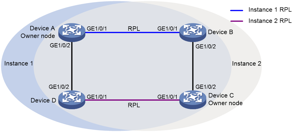
Configuration procedure
1. Configure Device A.
# Create VLANs 1 to 60, map VLANs 1 to 30 to MSTI 1, map VLANs 31 to 60 to MSTI 2, and activate the MST region configuration.
<DeviceA> system-view
[DeviceA] vlan 1 to 60
[DeviceA] stp region-configuration
[DeviceA-mst-region] instance 1 vlan 1 to 30
[DeviceA-mst-region] instance 2 vlan 31 to 60
[DeviceA-mst-region] active region-configuration
[DeviceA-mst-region] quit
# Disable the spanning tree feature on the port.
[DeviceA] interface gigabitethernet 1/0/1
[DeviceA-GigabitEthernet1/0/1] undo stp enable
# Configure the port as a trunk port and assign it to VLANs 1 to 60.
[DeviceA-GigabitEthernet1/0/1] port link-type trunk
[DeviceA-GigabitEthernet1/0/1] port trunk permit vlan 1 to 60
[DeviceA-GigabitEthernet1/0/1] quit
# Configure GigabitEthernet 1/0/2 in the same way GigabitEthernet 1/0/1 is configured.
[DeviceA] interface gigabitethernet 1/0/2
[DeviceA-GigabitEthernet1/0/2] undo stp enable
[DeviceA-GigabitEthernet1/0/2] port link-type trunk
[DeviceA-GigabitEthernet1/0/2] port trunk permit vlan 1 to 60
[DeviceA-GigabitEthernet1/0/2] quit
# Create ERPS ring 1.
[DeviceA] erps ring 1
# Configure ERPS ring member ports.
[DeviceA-erps-ring1] port0 interface gigabitethernet 1/0/1
[DeviceA-erps-ring1] port1 interface gigabitethernet 1/0/2
# Create ERPS instance 1.
[DeviceA-erps-ring1] instance 1
# Configure the node role.
[DeviceA-erps-ring1-inst1] node-role owner rpl port0
# Configure the control VLAN.
[DeviceA-erps-ring1-inst1] control-vlan 100
# Configure the protected VLANs.
[DeviceA-erps-ring1-inst1] protected-vlan reference-instance 1
# Enable ERPS for instance 1.
[DeviceA-erps-ring1-inst1] instance enable
[DeviceA-erps-ring1-inst1] quit
[DeviceA-erps-ring1] quit
# Create ERPS instance 2.
[DeviceA-erps-ring1] instance 2
# Configure the control VLAN.
[DeviceA-erps-ring1-inst2] control-vlan 110
# Configure the protected VLANs.
[DeviceA-erps-ring1-inst2] protected-vlan reference-instance 2
# Enable ERPS for instance 2.
[DeviceA-erps-ring1-inst2] instance enable
[DeviceA-erps-ring1-inst2] quit
[DeviceA-erps-ring1] quit
# Enable CFD, and create a level-5 MD named MD_A.
[DeviceA] cfd enable
[DeviceA] cfd md MD_A level 5
# Create Ethernet service instance 1, in which the MA is identified by a VLAN and serves VLAN 1.
[DeviceA] cfd service-instance 1 ma-id vlan-based md MD_A vlan 1
# Configure a MEP list in Ethernet service instance 1, create outward-facing MEP 1001 in Ethernet service instance 1, and enable CCM sending on GigabitEthernet 1/0/1.
[DeviceA] cfd meplist 1001 1002 service-instance 1
[DeviceA] interface gigabitethernet 1/0/1
[DeviceA-GigabitEthernet1/0/1] cfd mep 1001 service-instance 1 outbound
[DeviceA-GigabitEthernet1/0/1] cfd cc service-instance 1 mep 1001 enable
[DeviceA-GigabitEthernet1/0/1] quit
# Create Ethernet service instance 2, in which the MA is identified by a VLAN and serves VLAN 2.
[DeviceA] cfd service-instance 2 ma-id vlan-based md MD_A vlan 2
# Configure a MEP list in Ethernet service instance 2, create outward-facing MEP 2001 in Ethernet service instance 1, and enable CCM sending on GigabitEthernet 1/0/2.
[DeviceA] cfd meplist 2001 2002 service-instance 2
[DeviceA] interface gigabitethernet 1/0/2
[DeviceA-GigabitEthernet1/0/2] cfd mep 2001 service-instance 2 outbound
[DeviceA-GigabitEthernet1/0/2] cfd cc service-instance 2 mep 2001 enable
[DeviceA-GigabitEthernet1/0/2] quit
# Create track entry 1 and associate it with the CC function of CFD for MEP 1001 in Ethernet service instance 1.
[DeviceA] track 1 cfd cc service-instance 1 mep 1001
# Associate GigabitEthernet 1/0/1 with track entry 1 and bring up the port for ERPS instances 1 and 2.
[DeviceA] interface gigabitethernet 1/0/1
[DeviceA-GigabitEthernet1/0/1] port erps ring 1 instance 1 track 1
[DeviceA-GigabitEthernet1/0/1] port erps ring 1 instance 2 track 1
[DeviceA-GigabitEthernet1/0/1] undo shutdown
[DeviceA-GigabitEthernet1/0/1] quit
# Create track entry 2 and associate it with the CC function of CFD for MEP 2001 in Ethernet service instance 2.
[DeviceA] track 2 cfd cc service-instance 2 mep 2001
# Associate GigabitEthernet 1/0/2 with track entry 2 and bring up the port for ERPS instances 1 and 2.
[DeviceA] interface gigabitethernet 1/0/2
[DeviceA-GigabitEthernet1/0/2] port erps ring 1 instance 1 track 2
[DeviceA-GigabitEthernet1/0/2] port erps ring 1 instance 2 track 2
[DeviceA-GigabitEthernet1/0/2] undo shutdown
[DeviceA-GigabitEthernet1/0/2] quit
# Enable ERPS.
[DeviceA] erps enable
2. Configure Device B.
# Create VLANs 1 to 60, map VLANs 1 to 30 to MSTI 1, map VLANs 31 to 60 to MSTI 2, and activate the MST region configuration.
<DeviceB> system-view
[DeviceB] vlan 1 to 60
[DeviceB] stp region-configuration
[DeviceB-mst-region] instance 1 vlan 1 to 30
[DeviceB-mst-region] instance 2 vlan 31 to 60
[DeviceB-mst-region] active region-configuration
[DeviceB-mst-region] quit
# Disable the spanning tree feature on the port.
[DeviceB] interface gigabitethernet 1/0/1
[DeviceB-GigabitEthernet1/0/1] undo stp enable
# Configure the port as a trunk port and assign it to VLANs 1 to 60.
[DeviceB-GigabitEthernet1/0/1] port link-type trunk
[DeviceB-GigabitEthernet1/0/1] port trunk permit vlan 1 to 60
[DeviceB-GigabitEthernet1/0/1] quit
# Configure GigabitEthernet 1/0/2 in the same way GigabitEthernet 1/0/1 is configured.
[DeviceB] interface gigabitethernet 1/0/2
[DeviceB-GigabitEthernet1/0/2] undo stp enable
[DeviceB-GigabitEthernet1/0/2] port link-type trunk
[DeviceB-GigabitEthernet1/0/2] port trunk permit vlan 1 to 60
[DeviceB-GigabitEthernet1/0/2] quit
# Create ERPS ring 1.
[DeviceB] erps ring 1
# Configure ERPS ring member ports.
[DeviceB-erps-ring1] port0 interface gigabitethernet 1/0/1
[DeviceB-erps-ring1] port1 interface gigabitethernet 1/0/2
# Create ERPS instance 1.
[DeviceB-erps-ring1] instance 1
# Configure the node role.
[DeviceB-erps-ring1-inst1] node-role neighbor rpl port0
# Configure the control VLAN.
[DeviceB-erps-ring1-inst1] control-vlan 100
# Configure the protected VLANs.
[DeviceB-erps-ring1-inst1] protected-vlan reference-instance 1
# Enable ERPS for instance 1.
[DeviceB-erps-ring1-inst1] instance enable
[DeviceB-erps-ring1-inst1] quit
[DeviceB-erps-ring1] quit
# Create ERPS instance 2.
[DeviceB-erps-ring1] instance 2
# Configure the control VLAN.
[DeviceB-erps-ring1-inst2] control-vlan 110
# Configure the protected VLANs.
[DeviceB-erps-ring1-inst2] protected-vlan reference-instance 2
# Enable ERPS for instance 2.
[DeviceB-erps-ring1-inst2] instance enable
[DeviceB-erps-ring1-inst2] quit
[DeviceB-erps-ring1] quit
# Enable CFD, and create a level-5 MD named MD_A.
[DeviceB] cfd enable
[DeviceB] cfd md MD_A level 5
# Create Ethernet service instance 1, in which the MA is identified by a VLAN and serves VLAN 1.
[DeviceB] cfd service-instance 1 ma-id vlan-based md MD_A vlan 1
# Configure a MEP list in Ethernet service instance 1, create outward-facing MEP 1002 in Ethernet service instance 1, and enable CCM sending on GigabitEthernet 1/0/1.
[DeviceB] cfd meplist 1001 1002 service-instance 1
[DeviceB] interface gigabitethernet 1/0/1
[DeviceB-GigabitEthernet1/0/1] cfd mep 1002 service-instance 1 outbound
[DeviceB-GigabitEthernet1/0/1] cfd cc service-instance 1 mep 1002 enable
[DeviceB-GigabitEthernet1/0/1] quit
# Create Ethernet service instance 3, in which the MA is identified by a VLAN and serves VLAN 3.
[DeviceB] cfd service-instance 3 ma-id vlan-based md MD_A vlan 3
# Configure a MEP list in Ethernet service instance 3, create outward-facing MEP 3002 in Ethernet service instance 3, and enable CCM sending on GigabitEthernet 1/0/2.
[DeviceB] cfd meplist 3001 3002 service-instance 3
[DeviceB] interface gigabitethernet 1/0/2
[DeviceB-GigabitEthernet1/0/2] cfd mep 3002 service-instance 3 outbound
[DeviceB-GigabitEthernet1/0/2] cfd cc service-instance 3 mep 3002 enable
[DeviceB-GigabitEthernet1/0/2] quit
# Create track entry 1 and associate it with the CC function of CFD for MEP 1002 in Ethernet service instance 1.
[DeviceB] track 1 cfd cc service-instance 1 mep 1002
# Associate GigabitEthernet 1/0/1 with track entry 1 and bring up the port for ERPS instances 1 and 2.
[DeviceB] interface gigabitethernet 1/0/1
[DeviceB-GigabitEthernet1/0/1] port erps ring 1 instance 1 track 1
[DeviceB-GigabitEthernet1/0/1] port erps ring 1 instance 2 track 1
[DeviceB-GigabitEthernet1/0/1] undo shutdown
[DeviceB-GigabitEthernet1/0/1] quit
# Create track entry 2 and associate it with the CC function of CFD for MEP 3002 in Ethernet service instance 3.
[DeviceB] track 2 cfd cc service-instance 3 mep 3002
# Associate GigabitEthernet 1/0/2 with track entry 2 and bring up the port for ERPS instances 1 and 2.
[DeviceB] interface gigabitethernet 1/0/2
[DeviceB-GigabitEthernet1/0/2] port erps ring 1 instance 1 track 2
[DeviceB-GigabitEthernet1/0/2] port erps ring 1 instance 2 track 2
[DeviceB-GigabitEthernet1/0/2] undo shutdown
[DeviceB-GigabitEthernet1/0/2] quit
# Enable ERPS.
[DeviceB] erps enable
3. Configure Device C.
# Create VLANs 1 to 60, map VLANs 1 to 30 to MSTI 1, map VLANs 31 to 60 to MSTI 2, and activate the MST region configuration.
<DeviceC> system-view
[DeviceC] vlan 1 to 60
[DeviceC] stp region-configuration
[DeviceC-mst-region] instance 1 vlan 1 to 30
[DeviceC-mst-region] instance 2 vlan 31 to 60
[DeviceC-mst-region] active region-configuration
[DeviceC-mst-region] quit
# Disable the spanning tree feature on the port.
[DeviceC] interface gigabitethernet 1/0/1
[DeviceC-GigabitEthernet1/0/1] undo stp enable
# Configure the port as a trunk port and assign it to VLANs 1 to 60.
[DeviceC-GigabitEthernet1/0/1] port link-type trunk
[DeviceC-GigabitEthernet1/0/1] port trunk permit vlan 1 to 60
[DeviceC-GigabitEthernet1/0/1] quit
# Configure GigabitEthernet 1/0/2 in the same way GigabitEthernet 1/0/1 is configured.
[DeviceC] interface gigabitethernet 1/0/2
[DeviceC-GigabitEthernet1/0/2] undo stp enable
[DeviceC-GigabitEthernet1/0/2] port link-type trunk
[DeviceC-GigabitEthernet1/0/2] port trunk permit vlan 1 to 60
[DeviceC-GigabitEthernet1/0/2] quit
# Create ERPS ring 1.
[DeviceC] erps ring 1
# Configure ERPS ring member ports.
[DeviceC-erps-ring1] port0 interface gigabitethernet 1/0/1
[DeviceC-erps-ring1] port1 interface gigabitethernet 1/0/2
# Create ERPS instance 1.
[DeviceC-erps-ring1] instance 1
# Configure the control VLAN.
[DeviceC-erps-ring1-inst1] control-vlan 100
# Configure the protected VLANs.
[DeviceC-erps-ring1-inst1] protected-vlan reference-instance 1
# Enable ERPS for instance 1.
[DeviceC-erps-ring1-inst1] instance enable
[DeviceC-erps-ring1-inst1] quit
[DeviceC-erps-ring1] quit
# Create ERPS instance 2.
[DeviceC-erps-ring1] instance 2
# Configure the node role.
[DeviceC-erps-ring1-inst2] node-role owner rpl port0
# Configure the control VLAN.
[DeviceC-erps-ring1-inst2] control-vlan 110
# Configure the protected VLANs.
[DeviceC-erps-ring1-inst2] protected-vlan reference-instance 2
# Enable ERPS for instance 2.
[DeviceC-erps-ring1-inst2] instance enable
[DeviceC-erps-ring1-inst2] quit
[DeviceC-erps-ring1] quit
# Enable CFD, and create a level-5 MD named MD_A.
[DeviceC] cfd enable
[DeviceC] cfd md MD_A level 5
# Create Ethernet service instance 3, in which the MA is identified by a VLAN and serves VLAN 3.
[DeviceC] cfd service-instance 3 ma-id vlan-based md MD_A vlan 3
# Configure a MEP list in Ethernet service instance 3, create outward-facing MEP 3001 in Ethernet service instance 3, and enable CCM sending on GigabitEthernet 1/0/2.
[DeviceC] cfd meplist 3001 3002 service-instance 3
[DeviceC] interface gigabitethernet 1/0/2
[DeviceC-GigabitEthernet1/0/2] cfd mep 3001 service-instance 3 outbound
[DeviceC-GigabitEthernet1/0/2] cfd cc service-instance 3 mep 3001 enable
[DeviceC-GigabitEthernet1/0/2] quit
# Create Ethernet service instance 4, in which the MA is identified by a VLAN and serves VLAN 4.
[DeviceC] cfd service-instance 4 ma-id vlan-based md MD_A vlan 4
# Configure a MEP list in Ethernet service instance 4, create outward-facing MEP 4001 in Ethernet service instance 4, and enable CCM sending on GigabitEthernet 1/0/1.
[DeviceC] cfd meplist 4001 4002 service-instance 4
[DeviceC] interface gigabitethernet 1/0/1
[DeviceC-GigabitEthernet1/0/1] cfd mep 4001 service-instance 4 outbound
[DeviceC-GigabitEthernet1/0/1] cfd cc service-instance 4 mep 4001 enable
[DeviceC-GigabitEthernet1/0/1] quit
# Create track entry 1 and associate it with the CC function of CFD for MEP 3001 in Ethernet service instance 3.
[DeviceC] track 1 cfd cc service-instance 3 mep 3001
# Associate GigabitEthernet 1/0/2 with track entry 1 and bring up the port for ERPS instances 1 and 2.
[DeviceC] interface gigabitethernet 1/0/2
[DeviceC-GigabitEthernet1/0/2] port erps ring 1 instance 1 track 1
[DeviceC-GigabitEthernet1/0/2] port erps ring 1 instance 2 track 1
[DeviceC-GigabitEthernet1/0/2] undo shutdown
[DeviceC-GigabitEthernet1/0/2] quit
# Create track entry 2 and associate it with the CC function of CFD for MEP 4001 in Ethernet service instance 4.
[DeviceC] track 2 cfd cc service-instance 4 mep 4001
# Associate GigabitEthernet 1/0/1 with track entry 2 and bring up the port for ERPS instances 1 and 2.
[DeviceC] interface gigabitethernet 1/0/1
[DeviceC-GigabitEthernet1/0/1] port erps ring 1 instance 1 track 2
[DeviceC-GigabitEthernet1/0/1] port erps ring 1 instance 2 track 2
[DeviceC-GigabitEthernet1/0/1] undo shutdown
[DeviceC-GigabitEthernet1/0/1] quit
# Enable ERPS.
[DeviceC] erps enable
4. Configure Device D.
# Create VLANs 1 to 60, map VLANs 1 to 30 to MSTI 1, map VLANs 31 to 60 to MSTI 2, and activate the MST region configuration.
<DeviceD> system-view
[DeviceD] vlan 1 to 60
[DeviceD] stp region-configuration
[DeviceD-mst-region] instance 1 vlan 1 to 30
[DeviceD-mst-region] instance 2 vlan 31 to 60
[DeviceD-mst-region] active region-configuration
[DeviceD-mst-region] quit
# Disable the spanning tree feature on the port.
[DeviceD] interface gigabitethernet 1/0/1
[DeviceD-GigabitEthernet1/0/1] undo stp enable
# Configure the port as a trunk port and assign it to VLANs 1 to 60.
[DeviceD-GigabitEthernet1/0/1] port link-type trunk
[DeviceD-GigabitEthernet1/0/1] port trunk permit vlan 1 to 60
[DeviceD-GigabitEthernet1/0/1] quit
# Configure GigabitEthernet 1/0/2 in the same way GigabitEthernet 1/0/1 is configured.
[DeviceD] interface gigabitethernet 1/0/2
[DeviceD-GigabitEthernet1/0/2] undo stp enable
[DeviceD-GigabitEthernet1/0/2] port link-type trunk
[DeviceD-GigabitEthernet1/0/2] port trunk permit vlan 1 to 60
[DeviceD-GigabitEthernet1/0/2] quit
# Create ERPS ring 1.
[DeviceD] erps ring 1
# Configure ERPS ring member ports.
[DeviceD-erps-ring1] port0 interface gigabitethernet 1/0/1
[DeviceD-erps-ring1] port1 interface gigabitethernet 1/0/2
# Create ERPS instance 1.
[DeviceD-erps-ring1] instance 1
# Configure the control VLAN.
[DeviceD-erps-ring1-inst1] control-vlan 100
# Configure the protected VLANs.
[DeviceD-erps-ring1-inst1] protected-vlan reference-instance 1
# Enable ERPS for instance 1.
[DeviceD-erps-ring1-inst1] instance enable
[DeviceD-erps-ring1-inst1] quit
[DeviceD-erps-ring1] quit
# Create ERPS instance 2.
[DeviceD-erps-ring1] instance 2
# Configure the node role.
[DeviceD-erps-ring1-inst2] node-role neighbor rpl port0
# Configure the control VLAN.
[DeviceD-erps-ring1-inst2] control-vlan 110
# Configure the protected VLANs.
[DeviceD-erps-ring1-inst2] protected-vlan reference-instance 2
# Enable ERPS for instance 2.
[DeviceD-erps-ring1-inst2] instance enable
[DeviceD-erps-ring1-inst2] quit
[DeviceD-erps-ring1] quit
# Enable CFD, and create a level-5 MD named MD_A.
[DeviceD] cfd enable
[DeviceD] cfd md MD_A level 5
# Create Ethernet service instance 2, in which the MA is identified by a VLAN and serves VLAN 2.
[DeviceD] cfd service-instance 2 ma-id vlan-based md MD_A vlan 2
# Configure a MEP list in Ethernet service instance 2, create outward-facing MEP 2002 in Ethernet service instance 2, and enable CCM sending on GigabitEthernet 1/0/2.
[DeviceD] cfd meplist 2001 2002 service-instance 2
[DeviceD] interface gigabitethernet 1/0/2
[DeviceD-GigabitEthernet1/0/2] cfd mep 2002 service-instance 2 outbound
[DeviceD-GigabitEthernet1/0/2] cfd cc service-instance 2 mep 2002 enable
[DeviceD-GigabitEthernet1/0/2] quit
# Create Ethernet service instance 4, in which the MA is identified by a VLAN and serves VLAN 4.
[DeviceD] cfd service-instance 4 ma-id vlan-based md MD_A vlan 4
# Configure a MEP list in Ethernet service instance 4, create outward-facing MEP 4002 in Ethernet service instance 4, and enable CCM sending on GigabitEthernet 1/0/1.
[DeviceD] cfd meplist 4001 4002 service-instance 4
[DeviceD] interface gigabitethernet 1/0/1
[DeviceD-GigabitEthernet1/0/1] cfd mep 4002 service-instance 4 outbound
[DeviceD-GigabitEthernet1/0/1] cfd cc service-instance 4 mep 4002 enable
[DeviceD-GigabitEthernet1/0/1] quit
# Create track entry 1 and associate it with the CC function of CFD for MEP 2002 in Ethernet service instance 2.
[DeviceD] track 1 cfd cc service-instance 2 mep 2002
# Associate GigabitEthernet 1/0/2 with track entry 1 and bring up the port for ERPS instances 1 and 2.
[DeviceD] interface gigabitethernet 1/0/2
[DeviceD-GigabitEthernet1/0/2] port erps ring 1 instance 1 track 1
[DeviceD-GigabitEthernet1/0/2] port erps ring 1 instance 2 track 1
[DeviceD-GigabitEthernet1/0/2] undo shutdown
[DeviceD-GigabitEthernet1/0/2] quit
# Create track entry 2 and associate it with the CC function of CFD for MEP 4002 in Ethernet service instance 4.
[DeviceD] track 2 cfd cc service-instance 4 mep 4002
# Associate GigabitEthernet 1/0/1 with track entry 2 and bring up the port for ERPS instances 1 and 2.
[DeviceD] interface gigabitethernet 1/0/1
[DeviceD-GigabitEthernet1/0/1] port erps ring 1 instance 1 track 2
[DeviceD-GigabitEthernet1/0/1] port erps ring 1 instance 2 track 2
[DeviceD-GigabitEthernet1/0/1] undo shutdown
[DeviceD-GigabitEthernet1/0/1] quit
# Enable ERPS.
[DeviceD] erps enable
Verifying the configuration
# Display information about ERPS instance 1 for Device A.
[Device A] display erps detail ring 1
Ring ID : 1
Port0 : GigabitEthernet1/0/1
Port1 : GigabitEthernet1/0/2
Subring : No
Default MAC : No
Instance ID : 1
Node role : Owner
Node state : Idle
Connect(ring/instance): -
Control VLAN : 100
Protected VLAN : Reference-instance 1
Guard timer : 500 ms
Hold-off timer : 0 ms
WTR timer : 5 min
Revertive operation : Revertive
Enable status : Yes, Active status : Yes
R-APS level : 7
Port PortRole PortStatus
----------------------------------------------------------------------------
Port0 RPL Block
Port1 Non-RPL Up
Instance ID : 2
Node role : Normal
Node state : Idle
Connect(ring/instance): -
Control VLAN : 100
Protected VLAN : Reference-instance 2
Guard timer : 500 ms
Hold-off timer : 0 ms
WTR timer : 5 min
Revertive operation : Revertive
Enable status : Yes, Active status : Yes
R-APS level : 7
Port PortRole PortStatus
----------------------------------------------------------------------------
Port0 Non-RPL Up
Port1 Non-RPL Up
The output shows the following information:
· For ERPS instance 1:
¡ Device A is the owner node.
¡ The ERPS ring is in idle state.
¡ The RPL port is blocked.
¡ The non-RPL port is unblocked.
· For ERPS instance 2:
¡ Device A is a normal node.
¡ The ERPS ring is in idle state.
¡ The non-RPL port is unblocked.
Troubleshooting ERPS
Symptom
The link between the owner node and the faulty node is available, but the owner node cannot receive SF packets sent by the faulty node. The RPL port is blocked.
Analysis
Possible reasons include:
· ERPS is not enabled for some nodes on the ERPS ring.
· The ring IDs are different for the nodes on the same ERPS ring.
· The control VLAN IDs are different for the nodes in the same ERPS instance.
· The RPL port is faulty.
Solutions
To resolve the problem:
· Use the display erps command to examine whether ERPS is enabled for all nodes on the ERPS ring. If ERPS is disabled for some nodes, use the erps enable command to enable ERPS for the nodes.
· Set the same ring ID for all nodes on a ERPS ring and configure the same control VLAN for all nodes in an ERPS instance.
· Use the display erps detail command to examine the port status for all nodes. Bring up the ports in down state.
· Use the debugging erps command on all nodes to view debugging information about packets and node status.