- Table of Contents
-
- 12-High Availability Configuration Guides
- 00-Preface
- 01-Ethernet OAM configuration
- 02-CFD configuration
- 03-DLDP configuration
- 04-RRPP configuration
- 05-ERPS configuration
- 06-Smart Link configuration
- 07-Monitor Link configuration
- 08-VRRP configuration
- 09-Error code detection configuration
- 09-Reth interface and redundancy group configuration
- 10-BFD configuration
- 11-Track configuration
- 13-Process placement configuration
- Related Documents
-
| Title | Size | Download |
|---|---|---|
| 10-BFD configuration | 217.99 KB |
Contents
Single-hop detection and multihop detection
BFD session modes and operating modes
Configuration restrictions and guidelines
Configuring BFD sessions in echo packet mode
About BFD session creation methods
Configuring detection time settings
Configuring BFD sessions in control packet mode
About BFD session creation methods
Configuring a static BFD session
Configuring BFD session parameters for single-hop detection
Configuring BFD session parameters for multihop detection
Associating the interface state with BFD
Configuring the TTL value for BFD packets
Configuring BFD session flapping suppression
Forwarding the specified BFD echo packets through the peer link in an M-LAG system
Configuring BFD
Overview
Bidirectional forwarding detection (BFD) provides a general-purpose, standard, medium- and protocol-independent fast failure detection mechanism. It can detect and monitor the connectivity of forwarding paths to detect communication failures quickly so that measures can be taken to ensure service continuity and enhance network availability.
BFD can uniformly and quickly detect the failures of the bidirectional forwarding paths between two devices for upper-layer protocols such as routing protocols. The hello mechanism used by upper-layer protocols needs seconds to detect a link failure, while BFD can provide detection measured in milliseconds.
Mechanism
BFD establishes a session between two network devices to detect failures on the bidirectional forwarding paths between the devices and provide services for upper-layer protocols. BFD provides no neighbor discovery mechanism. Protocols that BFD services notify BFD of devices to which it needs to establish sessions. After a session is established, if no BFD control packet is received from the peer within the negotiated BFD interval, BFD notifies a failure to the protocol, which then takes appropriate measures.
Figure 1 describes the operation of BFD for OSPF.
1. OSPF discovers neighbors by sending Hello packets and establishes neighbor relationships.
2. After establishing neighbor relationships, OSPF notifies BFD of the neighbor information, including destination and source addresses.
3. BFD uses the information to establish BFD sessions.
Figure 1 BFD session establishment
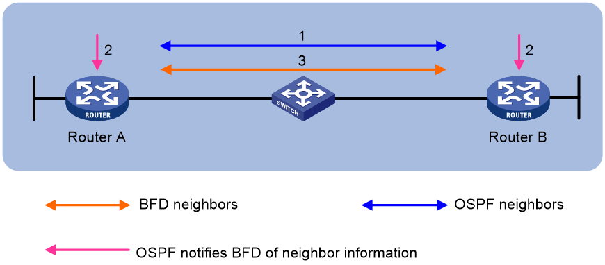
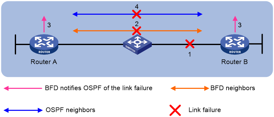
Figure 2 describes the BFD fault detection process.
4. BFD detects a link failure and tears down the session.
5. BFD notifies the neighbor unreachability to OSPF.
6. OSPF terminates the neighbor relationship on the link.
Single-hop detection and multihop detection
BFD can be used for single-hop and multihop detections.
· Single-hop detection—Detects the IP connectivity between two directly connected systems, for example, Device A and Device B as shown in Figure 3.

· Multihop detection—Detects any of the paths between two systems, for example, Device A and Device B as shown in Figure 4. These paths have multiple hops, and might overlap.

·
BFD session modes and operating modes
BFD sessions use echo packets and control packets.
Echo packet mode
Echo packets are encapsulated into UDP packets. The packet contains destination port 3785, a destination IP address (transmitting interface's IP address), and a source IP address (transmitting interface's IP address).
The local end of the link sends echo packets to establish BFD sessions and monitor link status. The peer end does not establish BFD sessions and only forwards the packets back to the originating end. If the local end does not receive echo packets from the peer end within the detection time, it considers the session to be down.
BFD sessions in echo packet mode do not require both ends to support BFD. Upon receiving BFD echo packets, the peer end loops back the packets for detection purposes.
In echo packet mode, BFD supports only single-hop detection and the BFD session is independent of the operating mode.
Control packet mode
The two ends of the link negotiate the establishment of BFD sessions by using the session parameters carried in control packets. Session parameters include session discriminators, desired minimum packet sending and receiving intervals, and local BFD session state.
Before a BFD session is established, BFD has two operating modes—active and passive.
· Active mode—BFD actively sends BFD control packets regardless of whether any BFD control packet is received from the peer.
· Passive mode—BFD does not send control packets until a BFD control packet is received from the peer.
At least one end must operate in active mode for a BFD session to be established.
After a BFD session is established, the two ends can operate in the following BFD operating modes:
· Asynchronous mode—The device periodically sends BFD control packets. The device considers that the session is down if it does not receive any BFD control packets within a specific interval. By default, BFD sessions are in Asynchronous mode.
· Demand mode—The Demand mode can be used to reduce the overhead when a large number of BFD sessions exist.
¡ The device periodically sends BFD control packets with the D bit set. If the peer end is operating in Asynchronous mode (default), the peer end stops sending BFD control packets after receiving control packets with the D bit set. In this case, BFD detects only the connectivity from the local end to the peer end. If the peer end does not receive control packets within the detection time, the session is declared to be down.
¡ If the peer end is operating in Demand mode, both ends stop sending BFD control packets. The system uses other mechanisms such as Hello mechanism and hardware detection to detect links.
In addition, both ends of the link can exchange BFD control packets to establish and maintain BFD sessions, and one end of the link sends echo packets to monitor link status.
Supported features
Table 1 shows the features supported by BFD.
Table 1 Features supported by BFD
|
Feature |
Reference |
|
Link aggregation |
Ethernet link aggregation in Layer 2—LAN Switching Configuration Guide |
|
IPv4 static routing |
Static routing in Layer 3—IP Routing Configuration Guide |
|
IPv6 static routing |
IPv6 static routing in Layer 3—IP Routing Configuration Guide |
|
RIP |
RIP in Layer 3—IP Routing Configuration Guide |
|
OSPF |
OSPF in Layer 3—IP Routing Configuration Guide |
|
OSPFv3 |
OSPFv3 in Layer 3—IP Routing Configuration Guide |
|
IS-IS |
IS-IS in Layer 3—IP Routing Configuration Guide |
|
BGP |
BGP in Layer 3—IP Routing Configuration Guide |
|
PIM |
PIM in IP Multicast Configuration Guide |
|
IPv6 PIM |
IPv6 PIM in IP Multicast Configuration Guide |
|
MPLS |
MPLS OAM in IP Multicast Configuration Guide |
|
RSVP |
RSVP in MPLS Configuration Guide |
|
Track |
"Configuring Track" |
Protocols and standards
· RFC 5880, Bidirectional Forwarding Detection (BFD)
· RFC 5881, Bidirectional Forwarding Detection (BFD) for IPv4 and IPv6 (Single Hop)
· RFC 5882, Generic Application of Bidirectional Forwarding Detection (BFD)
· RFC 5883, Bidirectional Forwarding Detection (BFD) for Multihop Paths
· RFC 5885, Bidirectional Forwarding Detection (BFD) for the Pseudowire Virtual Circuit Connectivity Verification (VCCV)
· RFC 7130, Bidirectional Forwarding Detection (BFD) on Link Aggregation Group (LAG) Interfaces
Configuration restrictions and guidelines
When the device operates in the expert mode, it does not support BFD if none of the following interface modules are installed:
· FD interface modules.
· FE interface modules.
· SG interface modules.
· SH interface modules.
Before configuring BFD basic functions, configure the network layer addresses of the interfaces so that adjacent nodes are reachable to each other at the network layer.
After a BFD session is established, the two ends negotiate BFD parameters, including minimum sending interval, minimum receiving interval, initialization mode, and packet authentication, by exchanging negotiation packets. They use the negotiated parameters without affecting the session status.
In an IRF fabric, if the detection time is smaller than the IRF link down report delay, the BFD session might flap. To prevent this problem, set the IRF link down report delay to be smaller than the detection time. For information about setting the IRF link down report delay, see IRF configuration in Virtual Technologies Configuration Guide.
By default, the device runs BFD version 1 and is compatible with BFD version 0. You cannot change the BFD version to 0 through commands. When the peer device runs BFD version 0, the local device automatically switches to BFD version 0.
Configuring BFD sessions in echo packet mode
About BFD session creation methods
A BFD session can be created manually by using the bfd static command or created dynamically through collaboration between an application module and BFD.
To avoid echo packet loss, do not configure the echo packet mode on a device with uRPF enabled. For more information about uRPF, see Security Configuration Guide.
Creating a static BFD session
About this task
A static BFD session in echo packet mode can be used to perform single-hop detection or multihop detection.
Restrictions and guidelines
You need to create a static BFD session in echo packet mode on only the local device to perform detection.
When creating a static BFD session, you must specify a peer IPv4 or IPv6 address. The system checks only the format of the IP address but not its correctness. If the peer IPv4 or IPv6 address is incorrect, the static BFD session cannot be established.
Different static BFD sessions cannot have the same local discriminator.
As a best practice, specify the source IP address for echo packets when creating a static BFD session. If you do not specify the source IP address, the device uses the IP address specified in the bfd echo-source-ip or bfd echo-source-ipv6 command as the source IP address of echo packets.
Creating a static BFD session for single-hop detection
|
Step |
Command |
Remarks |
|
1. Enter system view. |
system-view |
N/A |
|
2. Configure the source IP address of echo packets. |
· Configure the source IPv4 address of
echo packets: · Configure the source IPv6 address of echo
packets: |
By default, no source IP address is configured for echo packets. The source IP address cannot be on the same network segment as any local interface's IP address. Otherwise, a large number of ICMP redirect packets might be sent from the peer, resulting in link congestion. The source IPv6 address of echo packets can only be a global unicast address. |
|
3. Create a static BFD session and enter static BFD session view. |
IPv4: bfd static session-name [ peer-ip ipv4-address interface interface-type interface-number destination-ip ipv4-address [ source-ip ipv4-address ] one-arm-echo [ discriminator { auto | local local-value } ] ] IPv6: bfd static session-name [ peer-ipv6 ipv6-address interface interface-type interface-number destination-ipv6 ipv6-address [ source-ipv6 ipv6-address ] one-arm-echo [ discriminator { auto | local local-value } ] ] |
|
|
4. (Optional.) Specify a local discriminator for the static BFD session. |
discriminator local local-value |
By default, no local discriminator is specified. You can use this command only if you do not specify a local discriminator when creating a static BFD session. |
Creating a static BFD session for multihop detection
|
Step |
Command |
Remarks |
|
1. Enter system view. |
system-view |
N/A |
|
2. Configure the source IP address of echo packets. |
· Configure the source IPv4 address of
echo packets: · Configure the source IPv6 address of echo
packets: |
By default, no source IP address is configured for echo packets. The source IP address cannot be on the same network segment as any local interface's IP address. Otherwise, a large number of ICMP redirect packets might be sent from the peer, resulting in link congestion. The source IPv6 address of echo packets can only be a global unicast address. |
|
3. Create a static BFD session and enter static BFD session view. |
IPv4: bfd static session-name [ peer-ip ipv4-address [ vpn-instance vpn-instance-name ] destination-ip ipv4-address [ source-ip ipv4-address ] one-arm-echo[ discriminator { auto | local local-value } ] ] IPv6: bfd static session-name [ peer-ipv6 ipv6-address [ vpn-instance vpn-instance-name ] destination-ipv6 ipv6-address [ source-ipv6 ipv6-address ] one-arm-echo [ discriminator { auto | local local-value } ] ] |
|
|
4. (Optional.) Specify a local discriminator for the static BFD session. |
discriminator local local-value |
By default, no local discriminator is specified. You can use this command only if you do not specify a local discriminator when creating a static BFD session. |
Configuring detection time settings
About this task
When creating a BFD session in echo packet mode, you can configure the minimum interval for receiving BFD echo packets and the detection time multiplier for the device.
Configure detection time settings for single-hop BFD detection
|
Step |
Command |
Remarks |
|
1. Enter system view. |
system-view |
N/A |
|
2. Enter interface view or static BFD session view. |
· Enter interface view. · Enter static BFD session view. |
The static BFD session must already exist. To configure parameters for a static BFD session, you must enter its view. |
|
3. Set the minimum interval for receiving BFD echo packets. |
bfd min-echo-receive-interval interval |
The default setting is 400 milliseconds. On an S7503E-M switch, the default setting is 400 milliseconds for the LSQM1CTGS24QSFD0 MPU and is 1000 milliseconds for other MPUs. On a switch other than S7503E-M, the default setting is 400 milliseconds. |
|
4. Set the detection time multiplier. |
bfd detect-multiplier interval |
The default setting is 5. |
Configure detection time settings for single-hop BFD detection
|
Step |
Command |
Remarks |
|
1. Enter system view. |
system-view |
N/A |
|
2. (Optional.) Enter static BFD session view. |
bfd static session-name |
To configure parameters for a static BFD session, you must enter its view. |
|
3. Set the minimum interval for receiving BFD echo packets. |
bfd multi-hop min-echo-receive-interval interval |
The default setting is 400 milliseconds. On an S7503E-M switch, the default setting is 400 milliseconds for the LSQM1CTGS24QSFD0 MPU and is 1000 milliseconds for other MPUs. On a switch other than S7503E-M, the default setting is 400 milliseconds. |
|
4. Set the detection time multiplier. |
bfd multi-hop detect-multiplier value |
The default setting is 5. |
Configuring BFD sessions in control packet mode
About BFD session creation methods
BFD sessions in control packet mode can be created statically or established dynamically.
BFD sessions are distinguished by the local discriminator and remote discriminator in control packets. The main difference between a statically created session and a dynamically established session is that they obtain the local discriminator and remote discriminator in different ways.
· The local discriminator and remote discriminator of a static BFD session are specified manually in the bfd static command or in the commands that associate specific applications with BFD. For example, to use a static BFD session to detect MPLS LSPs, you must manually specify the local discriminator and remote discriminator. For more information, see MPLS OAM in MPLS Configuration Guide.
· The local discriminator of a dynamic BFD session is assigned by the device, and the remote discriminator is obtained during BFD session negotiation. The device can automatically assign the local discriminator to the BFD session in the following conditions:
¡ The auto keyword is specified for the bfd static command.
¡ The local and remote discriminators are not specified for the BFD session associated with a specific application.
Restrictions and guidelines
After an upper-layer protocol is configured to support BFD, the device automatically creates BFD sessions in control packet mode. You do not need to perform this task.
Devices operating in the expert mode do not support the bfd multi-hop destination-port command.
When the device operates in the expert mode, the minimum interval for receiving or transmitting control packets is in the range of 3 to 9 milliseconds for the LSQM1CTGS24QSFD0 MPU, and 3 to 99 milliseconds for other MPUs.
BFD version 0 does not support the following commands:
· bfd session init-mode.
· bfd authentication-mode.
· bfd demand enable.
· bfd echo enable.
Configuring a static BFD session
A static BFD session can be used for single-hop detection and multihop detection. By working with Track, a static BFD session can provide fast failure detection. For more information about Track association with BFD, see "Configuring Track."
If a static BFD session is created on the remote end, the static BFD session must be created on the local end.
When creating a static BFD session, you must specify a peer IPv4 or IPv6 address. The system checks only the format of the IP address but not its correctness. If the peer IPv4 or IPv6 address is incorrect, the static BFD session cannot be established.
Different static BFD sessions cannot have the same local discriminator.
To create a static BFD session for single-hop detection:
|
Step |
Command |
Remarks |
|
1. Enter system view. |
system-view |
N/A |
|
2. Create a static BFD session and enter static BFD session view. |
IPv4: bfd static session-name peer-ip ipv4-address interface interface-type interface-number source-ip ipv4-address [ discriminator { auto |local local-value remote remote-value } ] IPv6: bfd static session-name peer-ipv6 ipv6-address interface interface-type interface-number source-ipv6 ipv6-address [ discriminator { auto |local local-value remote remote-value } ] |
By default, no static BFD sessions exist. For a static BFD session to be established, specify the IPv6 address of the peer interface where the static BFD session resides for the peer-ipv6 ipv6-address option. Specify the IPv6 address of the local interface where the static BFD session resides for the source-ipv6 ipv6-address option. |
|
3. (Optional.) Specify the local and remote discriminators for the static BFD session.. |
discriminator { local local-value | remote remote-value } |
By default, no local discriminator or remote discriminator is specified for a static BFD session. Use this command only if you do not specify the local or remote discriminator when creating a static BFD session. |
To create a static BFD session for multihop detection:
|
Step |
Command |
Remarks |
|
1. Enter system view. |
system-view |
N/A |
|
2. Create a static BFD session and enter static BFD session view. |
IPv4: bfd static session-name peer-ip ipv4-address [ vpn-instance vpn-instance-name ] source-ip ipv4-address [ discriminator { auto |local local-value remote remote-value } ] [ track-interface interface-type interface-number ] IPv6: bfd static session-name peer-ipv6 ipv6-address [ vpn-instance vpn-instance-name ] source-ipv6 ipv6-address [ discriminator { auto |local local-value remote remote-value } ] [ track-interface interface-type interface-number ] |
By default, no static BFD sessions exist. |
|
3. (Optional.) Specify the local and remote discriminators for the static BFD session.. |
discriminator { local local-value | remote remote-value } |
By default, no local discriminator or remote discriminator is specified for a static BFD session. Use this command only if you do not specify the local or remote discriminator when creating a static BFD session. |
Configuring BFD session parameters for single-hop detection
|
Step |
Command |
Remarks |
|
1. Enter system view. |
system-view |
N/A |
|
2. Specify the mode for establishing a BFD session. |
bfd session init-mode { active | passive } |
By default, active is specified. BFD version 0 does not support this command. The configuration does not take effect. |
|
3. Enter interface view or static BFD session view. |
· Enter interface view: · Enter static BFD session view: |
N/A |
|
4. (Optional.) Configure the authentication mode for single-hop control packets. |
bfd authentication-mode { m-md5 | m-sha1 | md5 | sha1 | simple } key-id { cipher cipher-string | plain plain-string } |
By default, single-hop BFD packets are not authenticated. BFD version 0 does not support this command. The configuration does not take effect. When the system is operating in expert mode, it supports only the simple authentication mode. |
|
5. Enable the Demand BFD session mode. |
bfd demand enable |
By default, the BFD session is in Asynchronous mode. BFD version 0 does not support this command. The configuration does not take effect. This command is supported only in interface view. |
|
6. Set the minimum interval for receiving echo packets. |
bfd min-echo-receive-interval interval |
The default setting is 400 milliseconds. |
|
7. Set the minimum interval for transmitting single-hop BFD control packets. |
bfd min-transmit-interval interval |
The default setting is 400 milliseconds. |
|
8. Set the minimum interval for receiving single-hop BFD control packets. |
bfd min-receive-interval interval |
The default setting is 400 milliseconds. |
|
9. Set the single-hop detection time multiplier. |
bfd detect-multiplier value |
The default setting is 5. |
|
10. (Optional.) Set the delay timer for BFD to notify upper-layer protocols of session establishment failures. |
bfd init-fail-timer seconds |
By default, BFD does not notify upper-layer protocols of session establishment failures. For session establishment failures caused by configuration mismatches at the two ends, this command can cause the upper-layer protocol to act incorrectly. Therefore, use this command with caution. BFD status mismatch and BFD authentication configuration mismatch are examples of configuration mismatches. |
Configuring BFD session parameters for multihop detection
|
Step |
Command |
Remarks |
|
1. Enter system view. |
system-view |
N/A |
|
2. Specify the mode for establishing a BFD session. |
bfd session init-mode { active | passive } |
By default, active is specified. BFD version 0 does not support this command. The configuration does not take effect. |
|
3. (Optional.) Enter static BFD session view. |
bfd static session-name |
To configure parameters for a static BFD session, you must enter its view. |
|
4. (Optional.) Configure the authentication mode for multihop BFD control packets. |
bfd multi-hop authentication-mode { m-md5 | m-sha1 | md5 | sha1 | simple } key-id { cipher cipher-string | plain plain-string } |
By default, no authentication is performed. BFD version 0 does not support this command. The configuration does not take effect. When the system is operating in expert mode, it supports only the simple authentication mode. |
|
5. Configure the destination port number for multihop BFD control packets. |
bfd multi-hop destination-port port-number |
The default setting is 4784. Devices operating in the expert mode do not support this command. This command is supported only in system view. |
|
6. Set the multihop detection time multiplier. |
bfd multi-hop detect-multiplier value |
The default setting is 5. |
|
7. Set the minimum interval for receiving multihop BFD control packets. |
bfd multi-hop min-receive-interval interval |
The default setting is 400 milliseconds. |
|
8. Set the minimum interval for transmitting multihop BFD control packets. |
bfd multi-hop min-transmit-interval interval |
The default setting is 400 milliseconds. |
|
9. (Optional.) Set the delay timer for BFD to notify upper-layer protocols of session establishment failures. |
bfd init-fail-timer seconds |
By default, BFD does not notify upper-layer protocols of session establishment failures. |
For session establishment failures caused by configuration mismatches at the two ends, this command can cause the upper-layer protocol to act incorrectly. Therefore, use the bfd init-fail-timer seconds command with caution. BFD status mismatch and BFD authentication configuration mismatch are examples of configuration mismatches.
Enabling the echo function
When you use Asynchronous mode BFD to detect the connectivity between directly connected devices, you can enable the echo function. This function enables the local system to periodically send echo packets to the remote system and reduces the control packet receiving rate to save bandwidth usage. The remote system loops back the echo packets to the local system without processing them. If the local system does not receive echo packets looped back from the remote system in a consecutive number of times, the local system declares the BFD session down.
This function is supported only for single-hop detection.
This function does not take effect on BFD sessions associated with interface states.
To enable the echo function:
|
Step |
Command |
Remarks |
|
1. Enter system view. |
system-view |
N/A |
|
2. Enter interface view or static BFD session view. |
· Enter interface view: · Enter static BFD session view: |
The static BFD session must already exist. |
|
3. Enable the echo function. |
bfd echo [ receive | send ] enable |
By default, the echo function is disabled. |
Associating the interface state with BFD
About this task
By creating a BFD session for single-hop detection through exchange of BFD control packets, this feature implements fast link detection. When BFD detects a link fault, it sets the link layer protocol state to DOWN(BFD). This behavior helps applications relying on the link layer protocol state achieve fast convergence. The source IP address of control packets is specified manually, and the destination IP address is fixed at 224.0.0.184. As a best practice, specify the IP address of the interface as the source IP address. If the interface does not have an IP address, specify a unicast IP address other than 0.0.0.0 as the source IP address.
You can associate the state of the following interfaces with BFD:
· Layer 2 Ethernet interfaces.
· Member ports in a Layer 2 aggregation group.
· Layer 3 Ethernet interfaces.
· Member ports in a Layer 3 aggregation group.
· Layer 3 Ethernet subinterfaces.
The echo function does not take effect on BFD sessions associated with interface states.
To associate the interface state with BFD:
|
Step |
Command |
Remarks |
|
1. Enter system view. |
system-view |
N/A |
|
2. Enter interface view. |
interface interface-type interface-number |
N/A |
|
3. Associate the interface state with BFD. |
bfd echo [ receive | send ] enable |
If the peer device does not support obtaining BFD session discriminators through autonegotiation, you must specify the discriminators on both the local and peer devices. Without the discriminators, the BFD session cannot come up. |
|
4. (Optional.) Configure the timer that delays reporting the first BFD session establishment failure to the data link layer. |
bfd detect-interface first-fail-timer seconds |
By default, the first BFD session establishment failure is not reported to the data link layer. |
|
5. (Optional.) Enable special processing for BFD sessions. |
bfd detect-interface special-processing [ admin-down | authentication-change | session-up ] * |
By default, all types of special processing are disabled for BFD sessions. |
Configuring the TTL value for BFD packets
About this task
When you connect an H3C device to a third-party device, for successful BFD session negotiation, make sure the TTL value settings for BFD packets on both ends of the BFD session are the same. When the device receives a BFD packet in DOWN or INIT state from its peer, it verifies the TTL value of the packet and performs one of the following actions:
· For a single-hop BFD session, if the device receives a packet that carries a TTL value that is different from the TTL value specified with the bfd ttl command, the device drops the packet.
· For a multihop BFD session, if the device receives a packet that carries a TTL value that is greater than the TTL value specified with the bfd ttl command, the device drops the packet.
· If the BFD session is already up, the device sets the BFD session state to AdminDown, which triggers a BFD session renegotiation.
Restrictions and guidelines
· The bfd ttl command does not take effect on BFD sessions in echo packet mode.
· The bfd ttl command does not take effect on SBFD packets, and the device does not verify the TTL value in SBFD packets.
· For an IPv4 or IPv6 address with different mask lengths or prefix lengths, the device uses the TTL value specified with the longest mask or prefix length.
· For an IPv4 or IPv6 subnet, the TTL value of single-hop BFD packets must be greater than the TTL value of multihop BFD packets.
Procedure
|
Step |
Command |
Remarks |
|
1. Enter system view. |
system-view |
N/A |
|
2. Specify the TTL value for BFD packets. |
bfd { peer-ip ipv4-address mask-length | peer-ipv6 ipv6-address prefix-length } ttl { single-hop | multi-hop } ttl-value |
By default, the TTL value of single-hop BFD packets is 255 and the TTL value of multihop BFD packets is 64. |
Configuring BFD session flapping suppression
When BFD detects a link failure, it tears down the BFD session and notifies the upper-layer protocol of the failure. When the upper-layer protocol re-establishes a neighbor relationship, the BFD session comes up again. BFD session flaps occur when a link fails and recovers repeatedly, which consumes significant system resources and causes network instability.
This feature allows you to suppress BFD session flapping by using the initial-interval, secondary-interval, and maximum-interval arguments.
· A BFD session is suppressed within the specified interval. The suppression time does not exceed the maximum-interval.
· After a BFD session goes down for the second time, it cannot be re-established within the initial-interval.
· After a BFD session goes down for the third time, it cannot be re-established within the secondary-interval.
· After a BFD session goes down for the fourth time and at any later time, the following rules apply:
¡ If secondary-interval × 2n-3 is smaller than or equal to the maximum-interval, the BFD session cannot be re-established within the secondary-interval × 2n-3.
¡ If secondary-interval × 2n-3 is greater than the maximum-interval, the BFD session cannot be re-established within the maximum-interval.
The letter n, starting from 4, is the number of times the BFD session flaps.
To configure BFD session flapping suppression:
|
Step |
Command |
Remarks |
|
1. Enter system view. |
system-view |
N/A |
|
2. Configure BFD session flapping suppression. |
bfd dampening [ maximum maximum-interval initial initial-interval secondary secondary-interval ] |
By default, BFD sessions are not suppressed. The values for the initial-interval and secondary-interval arguments cannot be greater than the value for the maximum-interval argument. |
Forwarding the specified BFD echo packets through the peer link in an M-LAG system
About this task
Typically, only local discriminators are required for static BFD sessions in echo packet mode, and you do not need to configure remote discriminators. In an M-LAG system, a BFD session state anomaly might occur if the following conditions exist:
· AN M-LAG member device uses a static BFD session in echo packet mode to detect the link to the downlink device.
· The destination IP address in the BFD echo packets is the same as the IP address of the other M-LAG member device.
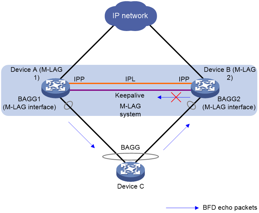
For example, as shown in Figure 5, Device C in the user network is dual-homed to an OSPF network through an M-LAG system. The M-LAG member devices are configured as gateways to implement Layer 3 forwarding. The gateway interfaces (for example, VLAN interfaces or VSI interfaces) on the M-LAG member devices use the same IP address and MAC address. Each M-LAG member device uses a static BFD session in echo packet mode to detect the link to Device C. The destination IP address in the BFD echo packets sent by the M-LAG member devices is the gateway IP address. Upon receiving the BFD echo packet sent by M-LAG 1, Device C might forward the packet to M-LAG 2. M-LAG 2 does not send the packet to M-LAG 1 because the destination IP address in the packet is the local device. Because no BFD echo packet is received from Device C, the BFD session state will become abnormal on M-LAG 1.
To resolve this issue, you can specify the local discriminator on M-LAG 1 for M-LAG 2 as a remote discriminator. Upon receiving a BFD echo packet matching a remote discriminator, M-LAG 2 sends the packet to M-LAG 1 through the peer link. This ensures that the BFD session on M-LAG 1 can come up correctly. Similarly, you can specify the local discriminator on M-LAG 2 for M-LAG 1 as a remote discriminator to ensure that the BFD session on M-LAG 2 can come up correctly.
Figure 5 BFD for M-LAG
Prerequisites
As a best practice, make sure the BFD session discriminators on the M-LAG member interfaces do not overlap in an M-LAG system.
Restrictions and guidelines
This feature is supported only on SH series interface modules.
After you specify a large number of remote discriminators for BFD sessions on the local device, BFD sessions might flap when you reboot the device. As a best practice to avoid this issue, use the link delay command to set the link-up event suppression interval to 30 seconds on M-LAG interfaces. For more information about the link delay command, see Ethernet link aggregation commands in Layer 2—LAN Switching Command Reference.
Procedure
|
Step |
Command |
Remarks |
|
1. Enter system view. |
system-view |
N/A |
|
2. Specify remote discriminators of static BFD sessions for the local device. |
bfd forwarding match remote-discriminator discr-value-list { discr-value1 [ to discr-value2 ] } &<1-10> |
By default, no remote discriminators of static BFD sessions are specified for the local device. |
Enabling SNMP notifications for BFD
To report critical BFD events to an NMS, enable SNMP notifications for BFD. For BFD event notifications to be sent correctly, you must also configure SNMP as described in Network Management and Monitoring Configuration Guide.
To enable SNMP notifications for BFD:
|
Command |
Remarks |
|
|
1. Enter system view. |
system-view |
N/A |
|
2. Enable SNMP notifications for BFD. |
snmp-agent trap enable bfd |
By default, SNMP notifications are enabled for BFD. |
Displaying and maintaining BFD
Execute the display command in any view and the reset command in user view.
|
Task |
Command |
|
Display BFD session information. |
display bfd session [ discriminator local local-value | static session-name | verbose ] display bfd session [ [ dynamic ] [ control | echo ] [ ip ] [ state { down | admin-down | init | up } ] [ discriminator remote remote-value ] [ peer-ip ipv4-address [ vpn-instance vpn-instance-name ] ] [ verbose ] ] display bfd session [ [ dynamic ] [ control | echo ] [ ipv6 ] [ state { down | admin-down | init | up } ] [ discriminator remote remote-value ] [ peer-ipv6 ipv6-address [ vpn-instance vpn-instance-name ] ] [ verbose ] ] display bfd session [ [ dynamic ] [ control | echo ] [ lsp | te | pw ] [ state { down | admin-down | init | up } ] [ discriminator remote remote-value ] [ [ peer-ip ipv4-address [ vpn-instance vpn-instance-name ] ] | [ peer-ipv6 ipv6-address [ vpn-instance vpn-instance-name ] ] ] [ verbose ] ] display bfd session [ [ static ] [ ip ] [ state { down | admin-down | init | up } ] [ discriminator remote remote-value ] [ peer-ip ipv4-address [ vpn-instance vpn-instance-name ] ] [ verbose ] display bfd session [ [ static ] [ ipv6 ] [ state { down | admin-down | init | up } ] [ discriminator remote remote-value ] [ peer-ipv6 ipv6-address [ vpn-instance vpn-instance-name ] ] [ verbose ] |
|
Display the TTL values for BFD packets. |
display bfd ttl |
|
Clear BFD session statistics. |
reset bfd session statistics |
