- Table of Contents
-
- 09-Security Configuration Guide
- 00-Preface
- 01-AAA configuration
- 02-802.1X configuration
- 03-MAC authentication configuration
- 04-Portal configuration
- 05-Web authentication configuration
- 06-Triple authentication configuration
- 07-Port security configuration
- 08-Password control configuration
- 09-Keychain configuration
- 10-Public key management
- 11-PKI configuration
- 12-IPsec configuration
- 13-SSH configuration
- 14-SSL configuration
- 15-Attack detection and prevention configuration
- 16-TCP attack prevention configuration
- 17-IP source guard configuration
- 18-ARP attack protection configuration
- 19-ND attack defense configuration
- 20-uRPF configuration
- 21-MFF configuration
- 22-FIPS configuration
- 23-MACsec configuration
- 24-802.1X client configuration
- 25-Microsegmentation configuration
- 26-Object group configuration
- Related Documents
-
| Title | Size | Download |
|---|---|---|
| 25-Microsegmentation configuration | 206.69 KB |
Contents
Components of microsegmentation
Restrictions and guidelines: Microsegmentation configuration
Microsegmentation tasks at a glance
Prerequisites for microsegmentation configuration
Configuring an aggregate microsegment
Configuring the microsegment extended community attribute
Configuring the network address match method for microsegments
Display and maintenance commands for microsegmentation
Microsegmentation configuration examples
Example: Configuring microsegmentation by using a QoS policy as the GBP in an IP network
Example: Configuring microsegmentation by using a PBR policy node as the GBP in an EVPN network
Configuring microsegmentation
About microsegmentation
The microsegmentation feature, also called group-based security segregation, controls traffic based on groups the traffic assigned to. For example, you can group servers in data centers based on specific criteria and apply traffic control policies to different groups.
Basic concepts
Microsegment
A microsegment groups endpoints (such as servers) based on specific criteria. Each microsegment has a globally unique ID.
Group-based policy
A group-based policy (GBP) is a microsegment-based traffic control policy can be implemented by using the following functions:
· PBR—A policy node corresponds to a GBP and controls communication between microsegments through the apply next-hop or apply output-interface null0 action. For more information about PBR, see Layer 3—IP Routing Configuration Guide.
· QoS policy—A class-behavior association corresponds to a GBP and controls communication between microsegments through the filter deny or filter permit action in the traffic behavior. For more information about QoS policy, see QoS configuration ACL and QoS Configuration Guide.
· Packet filtering—A packet filter corresponds to a GBP and controls communication between microsegments through the permit or deny rule in an ACL. For more information about packet filtering, see ACL configuration ACL and QoS Configuration Guide.
Components of microsegmentation
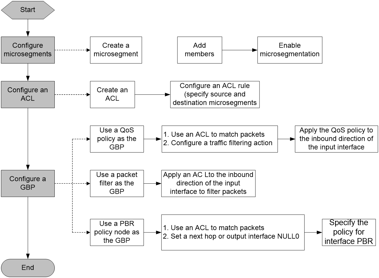
As shown in Figure 1, the microsegmentation feature contains the microsegment, ACL, and GBP settings. A GBP can be a QoS policy, a packet filter, or a PBR policy node.
This feature controls whether members in different microsegments can communicate. The GBP takes effect on the local end of a link. To control bidirectional traffic, configure this feature on both ends. Intermediate nodes do not require the configuration of this feature.
This feature can be used in IP, VXLAN, and EVPN networks. The configurations are slightly different in different networks.
· In an IP network, all settings must be configured on the Layer 3 gateway devices. In a VXLAN or EVPN network, all settings must be configured on the VTEPs.
· In an EVPN network, if the microsegment settings are automatically synchronized to the remote end through the BGP extended community attribute in the MAC/IP advertisement route, you do not need to configure microsegment settings on the remote end.
Figure 1 Microsegmentation configuration workflow
How microsegmentation works
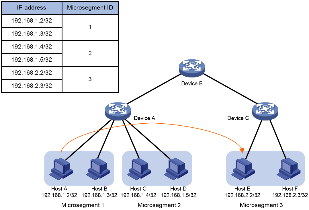
The microsegmentation feature works in the same way in IP, VXLAN, and EVPN networks. As shown in Figure 2, this section takes unidirectional traffic in an IP network as an example to illustrate how this feature works. This example uses a QoS policy as the GBP.
1. After receiving a packet sent from Host A to Host D, Device A obtains its source IP address (192.168.1.2) and destination IP address (192.168.1.5).
2. Device A searches the FIB table for the source IP address according to the longest match rule and determines that Host A belongs to microsegment 1.
3. Device A searches the FIB table for the destination IP address according to the longest match rule and determines that Host B belongs to microsegment 2.
4. Device A matches microsegment 1 and microsegment 2 against ACLs and executes one of the following actions in the QoS policy on matching packets:
¡ Forwards matching packets if the action is filter permit.
¡ Drops matching packets if the action is filter deny.
Figure 2 Forwarding of Layer 3 packets in an IP network
The microsegmentation feature works in the same way for cross-device packet forwarding.
Restrictions and guidelines: Microsegmentation configuration
When you use this feature to control unidirectional inter-VPN traffic, follow these restrictions and guidelines:
· On the source PE device, if the route guiding traffic forwarding is a network route, you must add the destination address of the route to a microsegment as a member.
· On the destination PE device, if the route is a host route, you must add the destination address of the route to a microsegment as a member.
Microsegmentation tasks at a glance
To configure microsegmentation, perform the following tasks:
2. (Optional.) Configuring an aggregate microsegment
Choose one option as needed:
¡ Configuring packet filtering
5. (Optional.) Configuring the microsegment extended community attribute
Perform this task in an EVPN network to avoid extended community attribute conflicts.
6. (Optional.) Configuring the network address match method for microsegments
Prerequisites for microsegmentation configuration
This feature can be used in IP, VXLAN, and EVPN networks. For information about configuring these features, see the relevant configuration guides.
Configuring a microsegment
Restrictions and guidelines
To control bidirectional traffic, follow these rules:
· In an IP or VXLAN network, configure the same microsegment settings on the two ends.
· In an EVPN network, configure a microsegment only on the local end. When distributing a MAC/IP advertisement route, the device carries the microsegment ID in the BGP extended community attribute. If the members (IP addresses) are in the distributed route, the microsegment settings are automatically synchronized to the remote end. The synchronized microsegment settings directly take effect on the remote end and are not subject to the microsegment enable command. If you also configure a microsegment on the remote end,, the synchronized microsegment settings overwrite the configured ones in the case of any setting differences.
For more information about MAC/IP advertisement routes, see EVPN overview in EVPN Configuration Guide.
Procedure
1. Enter system view.
system-view
2. Create a microsegment and enter microsegment view.
microsegment microsegment-id [ name microsegment-name ]
3. Add a member to the microsegment.
member ipv4 ipv4-address { mask | mask-length } [ vpn-instance vpn-instance-name ]
member ipv6 ipv6-address prefix-length [ vpn-instance vpn-instance-name ]
By default, a microsegment does not contain members.
4. (Optional.) Add users connected through the corresponding AC by mapping the microsegment interface to a VSI.
xconnect vsi
By default, a microsegment is not bound to any VSI.
The information about added users is not displayed in the display microsegment command output.
For more information about the xconnect vsi command, see VXLAN Command Reference.
5. Return to system view.
quit
6. Enable microsegmentation.
microsegment enable
By default, microsegmentation is disabled.
Configuring an aggregate microsegment
About this task
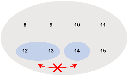
An aggregate microsegment is a group of microsegments with contiguous IDs. The ID of the aggregate microsegment is the start microsegment ID. You can use a mask to specify the member microsegments for an aggregate microsegment.
As shown in Figure 3, microsegments 8 through 15 can communicate with one another. To prevent communication between microsegments 12 and 14 and between microsegments 13 and 14, you can use an aggregate microsegment instead of reconfiguring microsegment settings. In this example, you can combine microsegments 12 and 13 to create an aggregate microsegment with ID 12, and use a GBP to prevent communication between aggregate microsegment 12 and microsegment 14.
Figure 3 Microsegment aggregation
Procedure
1. Enter system view.
system-view
2. Create an aggregate microsegment and enter its view.
microsegment aggregation aggregation-id mask-length mask-length [ name aggregation-name ]
Configuring an ACL
Restrictions and guidelines
To control bidirectional traffic, you must configure an ACL on both ends and configure an ACL rule with swapped source and destination microsegments on the two ends.
If you use a PBR policy node or a QoS policy as the GBP, the ACL rules must be permit rules. The apply action or QoS action is taken on matching packets.
If you use a packet filter as the GBP, the ACL rules can be permit or deny rules. Matching packets are permitted or denied.
If an ACL does not contain the vpn-instance vpn-instance-name option, it matches only non-VPN packets.
Procedure
1. Enter system view.
system-view
2. Create an IPv4 or IPv6 advanced ACL and enter its view. Choose one option as needed:
¡ acl [ ipv6 ] number acl-number [ name acl-name ] [ match-order { auto | config } ]
¡ acl [ ipv6 ] { advanced | basic } { acl-number | name acl-name } [ match-order { auto | config } ]
3. Configure a rule.
For more information, see the rule command in ACL and QoS Command Reference.
In the rule command, the destination microsegment microsegment-id and source microsegment microsegment-id options must be specified, and other parameters can be configured as needed.
Configuring a GBP
Configuring PBR
About this task
You can control communication between microsegments by referencing an ACL and specifying a next hop (permitting traffic) or the output interface NULL0 (dropping traffic) in a PBR policy.
For more information about PBR, see Layer 3—IP Routing Configuration Guide.
Restrictions and guidelines
To control bidirectional traffic, you must configure PBR on both ends.
Procedure
1. Enter system view.
system-view
2. Create a node for a policy, and enter its view.
policy-based-route policy-name [ deny | permit ] node node-number
3. Set an ACL match criterion for the node.
if-match acl { acl-number | name acl-name }
By default, no ACL match criterion is set.
4. Configure an action for the node. Choose one option as needed:
¡ Set a next hop.
apply next-hop ip-address
¡ Set NULL0 as the output interface.
apply output-interface null0
By default, no action is configured.
5. Return to system view.
quit
6. Specify the policy for interface PBR.
ip policy-based-route policy-name
By default, no interface policy is applied to an interface.
Configuring a QoS policy
About this task
You can use the traffic filtering action in a QoS policy to control communication between microsegments.
Procedure
1. Enter system view.
system-view
2. Define a traffic class.
a. Create a traffic class and enter traffic class view.
traffic classifier classifier-name [ operator { and | or } ]
b. Configure a match criterion.
if-match acl [ ipv6 ] { acl-number | name acl-name }
By default, no match criterion is configured.
Only IPv4 and IPv6 advanced ACLs can be used to match packets.
c. Return to system view.
quit
3. Define a traffic behavior.
a. Create a traffic behavior and enter traffic behavior view.
traffic behavior behavior-name
b. Configure a traffic filtering action.
filter { deny | permit }
By default, no traffic filtering action is configured.
c. Return to system view.
quit
4. Define a QoS policy.
a. Create a QoS policy and enter QoS policy view.
qos policy policy-name
b. Associate the traffic class with the traffic behavior in the QoS policy.
classifier classifier-name behavior behavior-name
By default, a traffic class is not associated with a traffic behavior.
c. Return to system view.
quit
5. Apply the QoS policy to an interface.
a. Enter interface view.
interface interface-type interface-number
b. Apply the QoS policy to the inbound direction of the interface.
qos apply policy policy-name inbound [ share-mode ]
By default, no QoS policy is applied to an interface.
Configuring packet filtering
About this task
You can apply an ACL to the inbound direction of an interface to control communication between microsegments.
Procedure
1. Enter system view.
system-view
2. Enter interface view.
interface interface-type interface-number
3. Apply an ACL to the inbound direction of the interface.
packet-filter [ ipv6 ] { acl-number | name acl-name } inbound
By default, no ACL is applied to an interface.
Configuring the microsegment extended community attribute
About this task
A MAC/IP advertisement route carries microsegment IDs in a BGP extended community attribute and advertises microsegment settings to a peer through the extended community attribute. For more information about MAC/IP advertisement routes, see EVPN overview in EVPN Configuration Guide.
To avoid attribute conflicts, you can perform this task to modify the microsegment extended community attribute value.
Procedure
1. Enter system view.
system-view
2. Enter BGP instance view.
bgp as-number [ instance instance-name ]
3. Set the microsegment extended community attribute value.
extcommunity-type microsegment-id microsegment-type-value
The default setting is 83ff (hexadecimal).
4. (Optional.) Display the microsegment extended community attribute value in BGP EVPN routes and the microsegment ID.
display bgp l2vpn evpn
For more information about this command, see EVPN commands in EVPN Command Reference.
5. (Optional.) Display the microsegment IDs carried in routes.
display ip routing-table
For more information about this command, see IP basics commands in Layer 3—IP Routing Command Reference.
Configuring the network address match method for microsegments
About this task
The device determines the segment membership of packets by matching the source and destination IP addresses of packets. The following match methods are available:
· Exact match—The mask lengths of the source and destination IP addresses must be equal to those of members in microsegments. For example, a packet sourced from 10.10.10.1/24 matches member 10.10.10.0/24 instead of 10.10.10.0/23.
· Longest match—The mask lengths of the source and destination IP addresses can be greater than or equal to those of members in microsegments. For example, a packet sourced from 10.10.10.1/24 matches member 10.10.10.0/16.
The device uses different match methods for different member types of microsegments:
· Host addresses (IPv4 addresses with a 32-bit mask and IPv6 addresses with a 128-bit prefix) use the longest match method, which cannot be modified.
· The default route (0.0.0.0/0 or 0::0/0) uses the exact match method, which cannot be modified.
· Network addresses (IPv4 addresses with a 1-bit to 31-bit mask and IPv6 addresses with a 1-bit to 127-bit prefix) use the exact match method by default. You can configure the longest match method for this member type.
The longest match method helps you simplify configuration when you need to add a large number of network addresses to a microsegment. For example, to match network addresses 10.10.10.0/24, 10.10.20.0/24, and 10.10.30.0/24 to microsegment 1, you need to execute only the member ipv4 10.10.10.0/16 command if you use longest match.
Procedure
1. Enter system view.
system-view
2. Configure the network address match method for microsegments.
microsegment subnet-match longest
By default, exact match is used for network addresses.
Display and maintenance commands for microsegmentation
Execute display commands in any view.
|
Task |
Command |
|
Display aggregate microsegment configuration. |
display microsegment aggregation [ aggregation-id | name aggregation-name ] |
|
Display microsegment configuration. |
display microsegment [ microsegment-id | name microsegment-name ] |
Microsegmentation configuration examples
Example: Configuring microsegmentation by using a QoS policy as the GBP in an IP network
Network configuration
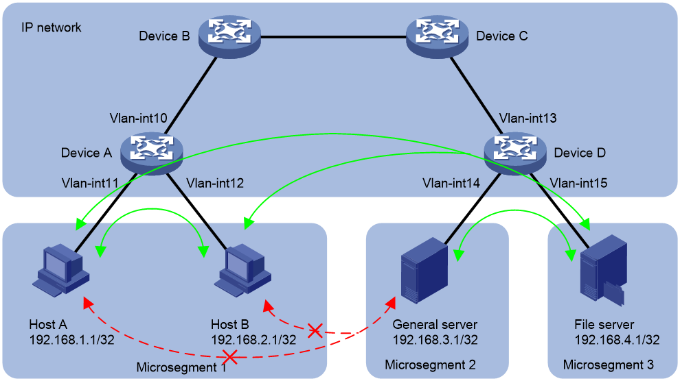
As shown in Figure 4, configure microsegmentation to meet the following requirements:
· Host A, Host B, and the general server can access the file server.
· Host A and the general server cannot access each other. Host B and the general server cannot access each other.
Analysis
1. Add Host A and Host B to microsegment 1.
2. Add the general server to microsegment 2, and add the file server to microsegment 3.
3. Configure a QoS policy to allow microsegment 1 and microsegment 3 to communicate, allow microsegment 2 and microsegment 3 to communicate, and prevent microsegment 1 and microsegment 2 from communicating.
Prerequisites
Before configuring microsegmentation, make sure the devices can reach one another.
Configuring Device A
1. Configure microsegments:
# Create microsegment 1, and add the IP addresses of Host A and Host B as its members.
<DeviceA> system-view
[DeviceA] microsegment 1 name EPG1
[DeviceA-microsegment-1] member ipv4 192.168.1.1 32
[DeviceA-microsegment-1] member ipv4 192.168.2.1 32
[DeviceA-microsegment-1] quit
# Create microsegment 2, and add the IP address of the general server as its member.
[DeviceA] microsegment 2 name EPG2
[DeviceA-microsegment-2] member ipv4 192.168.3.1 32
[DeviceA-microsegment-2] quit
# Create microsegment 3, and add the IP address of the file server as its member.
[DeviceA] microsegment 3 name EPG3
[DeviceA-microsegment-3] member ipv4 192.168.4.1 32
[DeviceA-microsegment-3] quit
# Enable microsegmentation.
[DeviceA] microsegment enable
2. Configure ACLs:
# Create an IPv4 advanced ACL named EPG1-EPG3, configure a rule to match the IP packets from microsegment 1 to microsegment 3.
[DeviceA] acl advanced name EPG1-EPG3
[DeviceA-acl-ipv4-adv-EPG1-EPG3] rule 0 permit ip source microsegment 1 destination microsegment 3
[Device-acl-ipv4-adv-EPG1-EPG3] quit
# Create an IPv4 advanced ACL named EPG1-EPG2, configure a rule to match the IP packets from microsegment 1 to microsegment 2.
[DeviceA] acl advanced name EPG1-EPG2
[DeviceA-acl-ipv4-adv-EPG1-EPG2] rule 0 permit ip source microsegment 1 destination microsegment 2
[DeviceA-acl-ipv4-adv-EPG1-EPG2] quit
3. Configuring a QoS policy:
# Create a traffic class named CLASSIFIER-GBP13, and use ACL EPG1-EPG3 as the match criterion.
[DeviceA] traffic classifier CLASSIFIER-GBP13
[DeviceA-classifier-CLASSIFIER-GBP13] if-match acl name EPG1-EPG3
[DeviceA-classifier-CLASSIFIER-GBP13] quit
# Create a traffic behavior named BEHAVIOR-GBP13, and configure a permit action.
[DeviceA] traffic behavior BEHAVIOR-GBP13
[DeviceA-behavior-BEHAVIOR-GBP13] filter permit
[DeviceA-behavior-BEHAVIOR-GBP13] quit
# Create a traffic class named CLASSIFIER-GBP12, and use ACL EPG1-EPG2 as the match criterion.
[DeviceA] traffic classifier CLASSIFIER-GBP12
[DeviceA-classifier-CLASSIFIER-GBP12] if-match acl name EPG1-EPG2
[DeviceA-classifier-CLASSIFIER-GBP12] quit
# Create a traffic behavior named BEHAVIOR-GBP12, and configure a deny action.
[DeviceA] traffic behavior BEHAVIOR-GBP12
[DeviceA-behavior-BEHAVIOR-GBP12] filter deny
[DeviceA-behavior-BEHAVIOR-GBP12] quit
# Create a QoS policy named GBP1, and associate the configured traffic classes and traffic behaviors in the QoS policy.
[DeviceA] qos policy GBP1
[DeviceA-qospolicy-GBP1] classifier CLASSIFIER-GBP13 behavior BEHAVIOR-GBP13
[DeviceA-qospolicy-GBP1] classifier CLASSIFIER-GBP12 behavior BEHAVIOR-GBP12
[DeviceA-qospolicy-GBP1] quit
# Apply QoS policy GBP1 to the inbound direction of Vlan-interface 11.
[DeviceA] interface vlan-interface 11
[DeviceA-Vlan-interface11] qos apply policy GBP1 inbound
[DeviceA-Vlan-interface11] quit
# Apply QoS policy GBP1 to the inbound direction of Vlan-interface 12.
[DeviceA] interface vlan-interface 12
[DeviceA-Vlan-interface12] qos apply policy GBP1 inbound
[DeviceA-Vlan-interface12] quit
Configuring Device D
1. Configure microsegments:
# Create microsegment 1, and add the IP addresses of Host A and Host B as its members.
<DeviceD> system-view
[DeviceD] microsegment 1 name EPG1
[DeviceD-microsegment-1] member ipv4 192.168.1.1 32
[DeviceD-microsegment-1] member ipv4 192.168.2.1 32
[DeviceD-microsegment-1] quit
# Create microsegment 2, and add the IP address of the general server as its member.
[DeviceD] microsegment 2 name EPG2
[DeviceD-microsegment-2] member ipv4 192.168.3.1 32
[DeviceD-microsegment-2] quit
# Create microsegment 3, and add the IP address of the file server as its member.
[DeviceD] microsegment 3 name EPG3
[DeviceD-microsegment-3] member ipv4 192.168.4.1 32
[DeviceD-microsegment-3] quit
# Enable microsegmentation.
[DeviceD] microsegment enable
2. Configure ACLs:
# Create an IPv4 advanced ACL named EPG3-EPG1, configure a rule to match the IP packets from microsegment 3 to microsegment 1.
<DeviceD> system-view
[DeviceD] acl advanced name EPG3-EPG1
[DeviceD-acl-ipv4-adv-EPG3-EPG1] rule 0 permit ip source microsegment 3 destination microsegment 1
[DeviceD-acl-ipv4-adv-EPG3-EPG1] quit
# Create an IPv4 advanced ACL named EPG2-EPG1, configure a rule to match the IP packets from microsegment 2 to microsegment 1.
[DeviceD] acl advanced name EPG2-EPG1
[DeviceD-acl-ipv4-adv-EPG2-EPG1] rule 0 permit ip source microsegment 2 destination microsegment 1
[DeviceD-acl-ipv4-adv-EPG2-EPG1] quit
# Create an IPv4 advanced ACL named EPG2-EPG3, configure a rule to match the IP packets from microsegment 2 to microsegment 3.
[DeviceD] acl advanced name EPG2-EPG3
[DeviceD-acl-ipv4-adv-EPG2-EPG3] rule 0 permit ip source microsegment 2 destination microsegment 3
[DeviceD-acl-ipv4-adv-EPG2-EPG3] quit
# Create an IPv4 advanced ACL named EPG3-EPG2, configure a rule to match the IP packets from microsegment 3 to microsegment 2.
[DeviceD] acl advanced name EPG3-EPG2
[DeviceD-acl-ipv4-adv-EPG3-EPG2] rule 0 permit ip source microsegment 3 destination microsegment 2
[DeviceD-acl-ipv4-adv-EPG3-EPG2] quit
3. Configuring a QoS policy:
# Create a traffic class named CLASSIFIER-GBP23, and use ACL EPG2-EPG3 as the match criterion.
[DeviceD] traffic classifier CLASSIFIER-GBP23
[DeviceD-classifier-CLASSIFIER-GBP23] if-match acl name EPG2-EPG3
[DeviceD-classifier-CLASSIFIER-GBP23] quit
# Create a traffic behavior named BEHAVIOR-GBP23, and configure a permit action.
[DeviceD] traffic behavior BEHAVIOR-GBP23
[DeviceD-behavior-BEHAVIOR-GBP23] filter permit
[DeviceD-behavior-BEHAVIOR-GBP23] quit
# Create a traffic class named CLASSIFIER-GBP21, and use ACL EPG2-EPG1 as the match criterion.
[DeviceD] traffic classifier CLASSIFIER-GBP21
[DeviceD-classifier-CLASSIFIER-GBP21] if-match acl name EPG2-EPG1
[DeviceD-classifier-CLASSIFIER-GBP21] quit
# Create a traffic behavior named BEHAVIOR-GBP21, and configure a deny action.
[DeviceD] traffic behavior BEHAVIOR-GBP21
[DeviceD-behavior-BEHAVIOR-GBP21] filter deny
[DeviceD-behavior-BEHAVIOR-GBP21] quit
# Create a QoS policy named GBP2, and associate the configured traffic classes and traffic behaviors in the QoS policy.
[DeviceD] qos policy GBP2
[DeviceD-qospolicy-GBP2] classifier CLASSIFIER-GBP23 behavior BEHAVIOR-GBP23
[DeviceD-qospolicy-GBP2] classifier CLASSIFIER-GBP21 behavior BEHAVIOR-GBP21
[DeviceD-qospolicy-GBP2] quit
# Apply QoS policy GBP2 to the inbound direction of Vlan-interface 14.
[DeviceD] interface vlan-interface 14
[DeviceD-Vlan-interface14] qos apply policy GBP2 inbound
[DeviceD-Vlan-interface14] quit
# Create a traffic class named CLASSIFIER-GBP31, and use ACL EPG3-EPG1 as the match criterion.
[DeviceD] traffic classifier CLASSIFIER-GBP31
[DeviceD-classifier-CLASSIFIER-GBP31] if-match acl name EPG3-EPG1
[DeviceD-classifier-CLASSIFIER-GBP31] quit
# Create a traffic behavior named BEHAVIOR-GBP31, and configure a permit action.
[DeviceD] traffic behavior BEHAVIOR-GBP31
[DeviceD-behavior-BEHAVIOR-GBP31] filter permit
[DeviceD-behavior-BEHAVIOR-GBP31] quit
# Create a traffic class named CLASSIFIER-GBP32, and use ACL EPG3-EPG2 as the match criterion.
[DeviceD] traffic classifier CLASSIFIER-GBP32
[DeviceD-classifier-CLASSIFIER-GBP32] if-match acl name EPG3-EPG2
[DeviceD-classifier-CLASSIFIER-GBP32] quit
# Create a traffic behavior named BEHAVIOR-GBP32, and configure a permit action.
[DeviceD] traffic behavior BEHAVIOR-GBP32
[DeviceD-behavior-BEHAVIOR-GBP32] filter permit
[DeviceD-behavior-BEHAVIOR-GBP32] quit
# Create a QoS policy named GBP3, and associate the configured traffic classes and traffic behaviors in the QoS policy.
[DeviceD] qos policy GBP3
[DeviceD-qospolicy-GBP3] classifier CLASSIFIER-GBP31 behavior BEHAVIOR-GBP31
[DeviceD-qospolicy-GBP3] classifier CLASSIFIER-GBP32 behavior BEHAVIOR-GBP32
[DeviceD-qospolicy-GBP3] quit
# Apply QoS policy GBP3 to the inbound direction of Vlan-interface 15.
[DeviceD] interface vlan-interface 15
[DeviceD-Vlan-interface15] qos apply policy GBP3 inbound
[DeviceD-Vlan-interface15] quit
Verifying the configuration
# Verify that Host A and Host B cannot successfully ping the general server.
C:\> ping 192.168.3.1
Pinging 192.168.3.1 with 32 bytes of data:
Request timed out
Request timed out
Request timed out
Request timed out
Ping statistics for 192.168.3.1:
Packets: Sent = 4, Received = 0, Lost = 4 (100% loss),
The output shows that Host A and Host B cannot successfully ping the general server.
# Verify that Host A and Host B can successfully ping the file server.
C:\> ping 192.168.4.1
Pinging 192.168.40.100 with 32 bytes of data:
Reply from 192.168.10.100: bytes=32 time=1ms TTL=255
Reply from 192.168.10.100: bytes=32 time<1ms TTL=255
Reply from 192.168.10.100: bytes=32 time<1ms TTL=255
Reply from 192.168.10.100: bytes=32 time<1ms TTL=255
Ping statistics for 192.168.10.100:
Packets: Sent = 4, Received = 4, Lost = 0 (0% loss),
Approximate round trip times in milli-seconds:
Minimum = 0ms, Maximum = 1ms, Average = 0ms
The output shows that Host A and Host B can successfully ping the file server.
# Display the configuration of each microsegment on Device A.
[DeviceA] display microsegment 1
Microsegment ID : 1
Microsegment name : EPG1
IPv4 member:
192.168.1.1/32
192.168.2.1/32
[DeviceA] display microsegment 2
Microsegment ID : 2
Microsegment name : EPG2
IPv4 member:
192.168.3.1/32
[DeviceA] display microsegment 3
Microsegment ID : 3
Microsegment name : EPG3
IPv4 member:
192.168.4.1/32
# Display summary information about microsegments on Device A.
[DeviceA] display microsegment
Microsegment status: Enabled
Total microsegments: 3
Microsegment list :
Microsegment ID Members Microsegment name
1 2 EPG1
2 1 EPG2
3 1 EPG3
# Display the configuration of ACLs on Device A.
[DeviceA] display acl all
Advanced IPv4 ACL named EPG1-EPG2, 1 rule,
ACL's step is 5, start ID is 0
rule 0 permit ip source microsegment 1 destination microsegment 2
Advanced IPv4 ACL named EPG1-EPG3, 1 rule,
ACL's step is 5, start ID is 0
rule 0 permit ip source microsegment 1 destination microsegment 3
# Display the configuration and statistics of QoS policies for interfaces on Device A.
[DeviceA] display qos policy interface
Interface: Vlan-interface11
Direction: Inbound
Policy: GBP1
Classifier: CLASSIFIER-GBP13
Matched : 0 (Packets) 0 (Bytes)
Operator: AND
Rule(s) :
If-match acl name EPG1-EPG3
Behavior: BEHAVIOR-GBP13
Filter enable: Permit
Classifier: CLASSIFIER-GBP12
Matched : 0 (Packets) 0 (Bytes)
Operator: AND
Rule(s) :
If-match acl name EPG1-EPG2
Behavior: BEHAVIOR-GBP12
Filter enable: Deny
Interface: Vlan-interface12
Direction: Inbound
Policy: GBP1
Classifier: CLASSIFIER-GBP13
Matched : 0 (Packets) 0 (Bytes)
Operator: AND
Rule(s) :
If-match acl name EPG1-EPG3
Behavior: BEHAVIOR-GBP13
Filter enable: Permit
Classifier: CLASSIFIER-GBP12
Matched : 0 (Packets) 0 (Bytes)
Operator: AND
Rule(s) :
If-match acl name EPG1-EPG2
Behavior: BEHAVIOR-GBP12
Filter enable: Deny
# Display the configuration of microsegments, and ACLs, and QoS policies on Device D. (Details not shown.)
Example: Configuring microsegmentation by using a PBR policy node as the GBP in an EVPN network
Network configuration
As shown in Figure 5, configure microsegmentation to meet the following requirements:
· Host A, Host B, and the general server can access the file server.
· Host A and the general server cannot access each other. Host B and the general server cannot access each other.
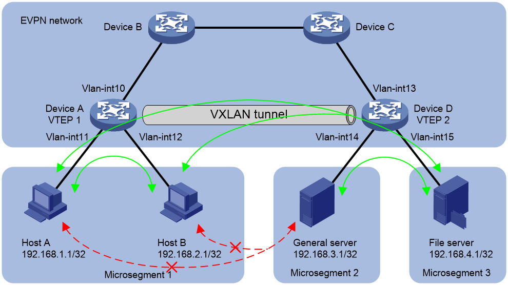
Analysis
1. Add Host A and Host B to microsegment 1.
2. Add the general server to microsegment 2, and add the file server to microsegment 3.
3. Configure PBR to allow microsegment 1 and microsegment 3 to communicate, allow microsegment 2 and microsegment 3 to communicate, and prevent microsegment 1 and microsegment 2 from communicating.
Restrictions and guidelines
Microsegments need to be configured only on Device A. BGP will synchronize the microsegment settings to Device D.
Prerequisites
Before configuring microsegmentation, configure EVPN-related settings. (Details not shown.)
Configuring Device A
1. Configure microsegments:
# Create microsegment 1, and add the IP addresses of Host A and Host B as its members.
<DeviceA> system-view
[DeviceA] microsegment 1 name EPG1
[DeviceA-microsegment-1] member ipv4 192.168.1.1 32
[DeviceA-microsegment-1] member ipv4 192.168.2.1 32
[DeviceA-microsegment-1] quit
# Create microsegment 2, and add the IP address of the general server as its member.
[DeviceA] microsegment 2 name EPG2
[DeviceA-microsegment-2] member ipv4 192.168.3.1 32
[DeviceA-microsegment-2] quit
# Create microsegment 3, and add the IP address of the file server as its member.
[DeviceA] microsegment 3 name EPG3
[DeviceA-microsegment-3] member ipv4 192.168.4.1 32
[DeviceA-microsegment-3] quit
# Enable microsegmentation.
[DeviceA] microsegment enable
2. Configure ACLs:
# Create an IPv4 advanced ACL named EPG1-EPG3, configure a rule to match the IP packets from microsegment 1 to microsegment 3.
[DeviceA] acl advanced name EPG1-EPG3
[DeviceA-acl-ipv4-adv-EPG1-EPG3] rule 0 permit ip source microsegment 1 destination microsegment 3
[Device-acl-ipv4-adv-EPG1-EPG3] quit
# Create an IPv4 advanced ACL named EPG1-EPG2, configure a rule to match the IP packets from microsegment 1 to microsegment 2.
[DeviceA] acl advanced name EPG1-EPG2
[DeviceA-acl-ipv4-adv-EPG1-EPG2] rule 0 permit ip source microsegment 1 destination microsegment 2
[DeviceA-acl-ipv4-adv-EPG1-EPG2] quit
3. Configuring PBR:
# Configure Node 0 for the policy GBP1 to forward the packets matching ACL EPG1-EPG3 to next hop 192.168.4.1. In this way, Host A and Host B in microsegment 1 can access the file server in microsegment 3.
[DeviceA] policy-based-route GBP1 node 0
[DeviceA-pbr-GBP1-0] if-match acl name EPG1-EPG3
[DeviceA-pbr-GBP1-0] apply next-hop 192.168.4.1
[DeviceA-pbr-GBP1-0] quit
# Configure Node 1 for the policy GBP1 to forward the packets matching ACL EPG1-EPG2 through output interface NULL0. In this way, Host A and Host B in microsegment 1 cannot access the general server in microsegment 2.
[DeviceA] policy-based-route GBP1 node 1
[DeviceA-pbr-GBP1-1] if-match acl name EPG1-EPG2
[DeviceA-pbr-GBP1-1] apply output-interface null0
[DeviceA-pbr-GBP1-1] quit
# Configure interface PBR by applying the policy GBP1 to VLAN-interface 11.
[DeviceA] interface vlan-interface 11
[DeviceA-Vlan-interface11] ip policy-based-route GBP1
[DeviceA-Vlan-interface11] quit
# Configure interface PBR by applying the policy GBP1 to VLAN-interface 12.
[DeviceA] interface vlan-interface 12
[DeviceA-Vlan-interface12] ip policy-based-route GBP1
[DeviceA-Vlan-interface12] quit
Configuring Device D
4. Configure ACLs:
# Create an IPv4 advanced ACL named EPG3-EPG1, configure a rule to match the IP packets from microsegment 3 to microsegment 1.
<DeviceD> system-view
[DeviceD] acl advanced name EPG3-EPG1
[DeviceD-acl-ipv4-adv-EPG3-EPG1] rule 0 permit ip source microsegment 3 destination microsegment 1
[DeviceD-acl-ipv4-adv-EPG3-EPG1] quit
# Create an IPv4 advanced ACL named EPG2-EPG1, configure a rule to match the IP packets from microsegment 2 to microsegment 1.
[DeviceD] acl advanced name EPG2-EPG1
[DeviceD-acl-ipv4-adv-EPG2-EPG1] rule 0 permit ip source microsegment 2 destination microsegment 1
[DeviceD-acl-ipv4-adv-EPG2-EPG1] quit
# Create an IPv4 advanced ACL named EPG2-EPG3, configure a rule to match the IP packets from microsegment 2 to microsegment 3.
[DeviceD] acl advanced name EPG2-EPG3
[DeviceD-acl-ipv4-adv-EPG2-EPG3] rule 0 permit ip source microsegment 2 destination microsegment 3
[DeviceD-acl-ipv4-adv-EPG2-EPG3] quit
# Create an IPv4 advanced ACL named EPG3-EPG2, configure a rule to match the IP packets from microsegment 3 to microsegment 2.
[DeviceD] acl advanced name EPG3-EPG2
[DeviceD-acl-ipv4-adv-EPG3-EPG2] rule 0 permit ip source microsegment 3 destination microsegment 2
[DeviceD-acl-ipv4-adv-EPG3-EPG2] quit
5. Configuring PBR:
# Configure Node 0 for the policy GBP2 to forward the packets matching ACL EPG2-EPG3 to next hop 192.168.4.1. In this way, the general server in microsegment 2 can access the file server in microsegment 3.
[DeviceD] policy-based-route GBP2 node 0
[DeviceD-pbr-GBP2-0] if-match acl name EPG2-EPG3
[DeviceD-pbr-GBP2-0] apply next-hop 192.168.4.1
[DeviceD-pbr-GBP2-0] quit
# Configure Node 1 for the policy GBP2 to forward the packets matching ACL EPG2-EPG1 through output interface NULL0. In this way, the general server in microsegment 2 cannot access Host A or Host B in microsegment 1.
[DeviceD] policy-based-route GBP2 node 1
[DeviceD-pbr-GBP2-1] if-match acl name EPG2-EPG1
[DeviceD-pbr-GBP2-1] apply output-interface null0
[DeviceD-pbr-GBP2-1] quit
# Configure Node 0 for the policy GBP3 to forward the packets matching ACL EPG3-EPG1 to next hop 192.168.1.1 or 192.168.2.1. In this way, the file server in microsegment 3 can access Host A and Host B in microsegment 1.
[DeviceD] policy-based-route GBP3 node 0
[DeviceD-pbr-GBP3-0] if-match acl name EPG3-EPG1
[DeviceD-pbr-GBP3-0] apply next-hop 192.168.1.1 192.168.2.1
[DeviceD-pbr-GBP3-0] quit
# Configure Node 1 for the policy GBP3 to forward the packets matching ACL EPG3-EPG2 to next hop 192.168.3.1. In this way, the file server in microsegment 3 can access the general server in microsegment 2.
[DeviceD] policy-based-route GBP3 node 1
[DeviceD-pbr-GBP3-1] if-match acl name EPG3-EPG2
[DeviceD-pbr-GBP3-1] apply next-hop 192.168.3.1
[DeviceD-pbr-GBP3-1] quit
# Configure interface PBR by applying the policy GBP2 to VLAN-interface 14.
[DeviceD] interface vlan-interface 14
[DeviceD-Vlan-interface14] ip policy-based-route GBP2
[DeviceD-Vlan-interface14] quit
# Configure interface PBR by applying the policy GBP3 to VLAN-interface 15.
[DeviceD] interface vlan-interface 15
[DeviceD-vlan-interface15] ip policy-based-route GBP3
[DeviceD-vlan-interface15] quit
Verifying the configuration
# Verify that Host A and Host B cannot successfully ping the general server.
C:\> ping 192.168.3.1
Pinging 192.168.3.1 with 32 bytes of data:
Request timed out
Request timed out
Request timed out
Request timed out
Ping statistics for 192.168.3.1:
Packets: Sent = 4, Received = 0, Lost = 4 (100% loss),
The output shows that Host A and Host B cannot successfully ping the general server.
# Verify that Host A and Host B can successfully ping the file server.
C:\> ping 192.168.4.1
Pinging 192.168.40.100 with 32 bytes of data:
Reply from 192.168.10.100: bytes=32 time=1ms TTL=255
Reply from 192.168.10.100: bytes=32 time<1ms TTL=255
Reply from 192.168.10.100: bytes=32 time<1ms TTL=255
Reply from 192.168.10.100: bytes=32 time<1ms TTL=255
Ping statistics for 192.168.10.100:
Packets: Sent = 4, Received = 4, Lost = 0 (0% loss),
Approximate round trip times in milli-seconds:
Minimum = 0ms, Maximum = 1ms, Average = 0ms
The output shows that Host A and Host B can successfully ping the file server.
# Display the configuration of each microsegment on Device A.
[DeviceA] display microsegment 1
Microsegment ID : 1
Microsegment name : EPG1
IPv4 member:
192.168.1.1/32
192.168.2.1/32
[DeviceA] display microsegment 2
Microsegment ID : 2
Microsegment name : EPG2
IPv4 member:
192.168.3.1/32
[DeviceA] display microsegment 3
Microsegment ID : 3
Microsegment name : EPG3
IPv4 member:
192.168.4.1/32
# Display summary information about microsegments on Device A.
[DeviceA] display microsegment
Microsegment status: Enabled
Total microsegments: 3
Microsegment list :
Microsegment ID Members Microsegment name
1 2 EPG1
2 1 EPG2
3 1 EPG3
# Display the configuration of ACLs on Device A.
[DeviceA] display acl all
Advanced IPv4 ACL named EPG1-EPG2, 1 rule,
ACL's step is 5, start ID is 0
rule 0 permit ip source microsegment 1 destination microsegment 2
Advanced IPv4 ACL named EPG1-EPG3, 1 rule,
ACL's step is 5, start ID is 0
rule 0 permit ip source microsegment 1 destination microsegment 3
# Display the configuration and statistics of PBR policies for interfaces on Device A.
[DeviceA] display ip policy-based-route interface vlan-interface 11
Policy-based routing information for interface Vlan-interface11:
Policy name: GBP1
node 0 permit:
if-match acl name EPG1-EPG3
apply next-hop 192.168.4.1
Matches: 20, bytes: 20000
node 1 permit:
if-match acl name EPG1-EPG2
apply output-interface NULL0
Matches: 4, bytes: 4000
Total matches: 24, total bytes: 24000
[DeviceA] display ip policy-based-route interface vlan-interface 12
Policy-based routing information for interface Vlan-interface12:
Policy name: GBP1
node 0 permit:
if-match acl name EPG1-EPG3
apply next-hop 192.168.4.1
Matches: 20, bytes: 20000
node 1 permit:
if-match acl name EPG1-EPG2
apply output-interface NULL0
Matches: 4, bytes: 4000
Total matches: 24, total bytes: 24000
# Display the configuration of microsegments, and ACLs, and PBR policies on Device D. (Details not shown.)