- Table of Contents
- Related Documents
-
| Title | Size | Download |
|---|---|---|
| 01-Text | 871.25 KB |
1 Terminology and basic knowledge for lightning protection
Classification of lightning strokes
Lightning strokes on network devices
General grounding requirements
Grounding the device by using a grounding strip
Grounding the switch with a grounding conductor buried in the earth ground
Grounding the switch by using an AC power cord
Equipotential bonding connection
6 Installing lightning arresters
Installing a power lightning arrester
Installing a signal lightning arrester
Lightning arrester installation example
7 Installing the lightning protection system in a wiring closet
Lightning protection installation in a wiring closet
Restrictions and guidelines for lightning protection system installation
9 Appendix Measurement of grounding resistance
1 Terminology and basic knowledge for lightning protection
Terminology
|
Terminology |
Description |
|
Lightning stroke |
A single electrical discharge in a lightning flash to earth. |
|
Direct lightning flash |
A lightning flash that directly strikes a building or lightning protection facility. |
|
Induced lightning flash |
Because of the rapid change of lightning current, a transient strong electromagnetic field is generated in the surrounding space, resulting in a high induced electromotive force on the nearby conductor. |
|
Lighting overvoltage |
Transient overvoltage on a point caused by a lightning stroke. |
|
Air-termination system |
Part of an external lightning protection system (LPS) using metallic elements such as rods, mesh conductors or catenary wires intended to intercept lightning flashes. |
|
Down-conductor system |
Part of an external lightning protection system (LPS) intended to conduct lightning current from the air-termination system to the earth-termination system. |
|
Surge protective device (SPD) |
Device intended to limit transient overvoltage and divert surge currents; contains at least one non-linear component. An SPD is also called a lightning arrester in this document. |
|
Earth |
The conductive mass of the earth, whose electric potential at any point is conventionally taken as equal to zero |
|
Earth electrode |
A conductive part or a group of conductive parts that are in intimate contact with the earth and provide an electrical connection. |
|
Earthing grid |
Part of an earthing installation that is restricted to the earth electrodes and their interconnections. |
|
Earthing connection |
Connection between the earth electrode and grounding strip. |
|
Earthing arrangement |
All the electrical connections and devices involved in the earthing of a system, installation, or equipment |
|
Equipotential bonding |
An electrical connection that connects grounding terminals of connected devices to reach the same or potential voltage. |
|
Common earthing system |
Grounding system that connects the following: · Lightning protection facilities of all parts. · Metal structures of the building. · Low voltage electrical distribution PE wire. · Equipotential bonding strip. · Equipment protection earthing. · Shielding body earthing. · ESD grounding. · Earthing facilities. |
Basic knowledge
Lightning strokes might cause extensive damage to devices and interrupt the operation of the entire system. It is crucial to protect devices from lightning strokes.
Classification of lightning strokes
· Direct lightning flash—A lightning flash that directly strikes a building, frame, tree, animal, or plant. It can directly destroy buildings and frames and cause casualties because of electrical and thermal effects.
· Induced lightning flash—The discharge between thunder clouds or between thunder clouds and the ground generates induced voltage on nearby overhead lines, buried lines, metal pipelines, or similar conductors. The induced voltage is transmitted to devices through conductors, resulting in damage to the devices.
Lightning strokes on network devices
· A direct lightning stroke is diverted to the earth directly through an air-termination system, which causes potential around the earthing grid to rise. Overvoltage is drawn to the devices along the grounding cables, damaging the devices.
· When the lightning current is led into the ground through the lightning down conductor, high current rate change causes a strong magnetic field in the vicinity of the down conductor. Overvoltage is induced on the surrounding devices.
· When the power lines or communication lines in and out of a building or an equipment room are hit by a lightning stroke, overvoltage and overcurrent run into the devices along the lines and damage the devices.
Lightning protection
Typically a building uses a lightning rod against direct lightning strokes. However, the power cords and signal cables of electronic devices might easily carry induced currents caused by lightning strokes to the devices. Therefore, you must build a comprehensive lightning protection system for an electronic information system in a building, including an external and internal lightning protection system.
Figure1-1 Comprehensive lightning protection system
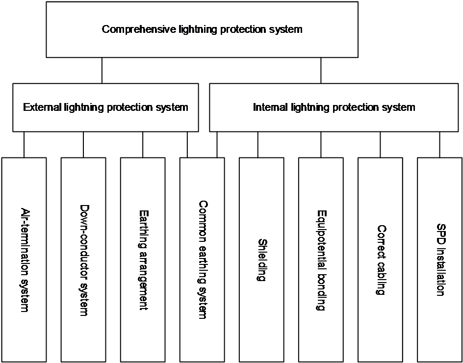
· The external lightning protection system contains air-termination system, down-conductor system, and earthing arrangement. The system mainly protects the building against direct lightning strokes.
· The internal lightning protection system contains an equipotential bonding system, common grounding system, shielding system, correct cable routing, and lightning arrester. The system reduces and prevents the EM effects of overcurrent caused by lightning strokes.
2 General requirements
H3C devices use the internal lightning protection system shown in Figure1-1. Lightning protection is typically performed from grounding, routing cables, and equipotential bonding.
Grounding
Reliable grounding is crucial for lightning protection and anti-interference. To ground the devices correctly and reliably, follow all the guidelines in this section.
Routing cables
To minimize the impact of induced lightning strokes on devices and enhances resistance against interference, follow these guidelines to route power cords and signal cables:
· Avoid routing cables overhead and along roofs outdoors.
· Route different types of cables separately.
Equipotential bonding
Equipotential bonding is designed to reduce the potential difference between metal components and the system. It can effectively reduce overvoltage occurrences caused by lightning strokes.
3 Grounding
General grounding requirements
· To quickly discharge overvoltage and overcurrent caused by lightning strokes or other reasons, ground all the uncharged metal components on the device. Uncharged metal components include grounding terminals on the chassis, metal sheaths or shields on outdoor cables, and signal lightning arresters on cables. When AC power is used, you can use the PE wire to ground the device. When DC power is used, ground the positive electrode of the 48V DC power source at the DC power outlet on the power distribution cabinet.
· Design the lightning protection grounding system based on the principles of voltage balance and equal potential. All the grounding facilities share a group of grounding conductors.
· Follow these guidelines to select and route a grounding cable:
¡ Use a short and thick yellow and green plastic insulated copper wire (not aluminum) as the grounding cable. Do not use other equipment as the electrical connection part of a grounding cable.
¡ As a best practice, use the yellow and green grounding cable provided with the device. Alternatively, you can use the optional yellow and green grounding cable. If you choose to purchase a grounding cable yourself, make sure the cross-sectional area of the grounding cable is greater than or equal to that of the power cord provided with the device.
¡ Make sure the cross-sectional area of the grounding cable that connects the rack grounding strip and the building grounding is greater than or equal to 6 mm2 (0.0093 sq in) and the length of the grounding cable does not exceed 30 m (98.43 ft). If the connection distance is greater than 30 m (98.43 ft), add a new grounding strip or rearrange the grounding strips to reduce the length required for the grounding cable.
¡ Do not lay a grounding cable and a signal cable in parallel or entangle them.
¡ Do not add a connector, switch, or fuse to a grounding cable.
¡ Ensure good electrical contact at the connection points at both ends of a grounding cable. To protect the connection points from corrosion, coat them with antirust paint, silicone, or paint powders.
Grounding methods
· Grounding the device by using a grounding strip
· Grounding the switch with a grounding conductor buried in the earth ground
· Grounding the switch by using an AC power cord
If part of a cable is routed outdoors, ground the metal sheath or shield of the outdoor part reliably. Connect the cable to the earthing grid by the shortest possible route.
If you install a lightning arrester for a cable, ground the lightning arrester reliably. For more information, see "Installing a power lightning arrester" and "Installing a signal lightning arrester."
Grounding the device by using a grounding strip
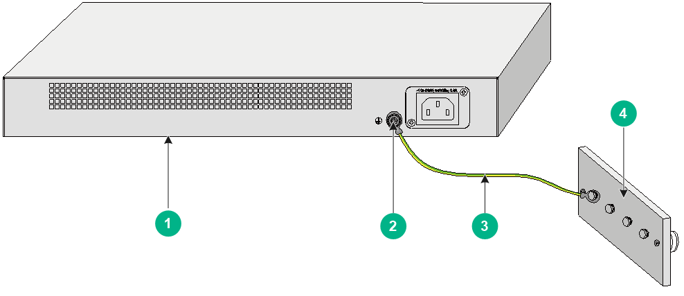
If a grounding strip is available at the installation site, attach one end of the grounding cable to a grounding post on the grounding strip and fasten it with a nut. As a best practice, use the provided or optional yellow and green grounding cable. Make sure the grounding cable is as short as possible and do not wind the cable. When you connect a grounding cable to a grounding strip outdoors, treat it with anti-corrosion measures.
Figure3-1 Grounding the switch by using a grounding strip
|
(1) Device (rear panel) |
(2) Grounding screw on the device |
|
(3) Grounding wire |
(4) Grounding strip |
Grounding the switch with a grounding conductor buried in the earth ground
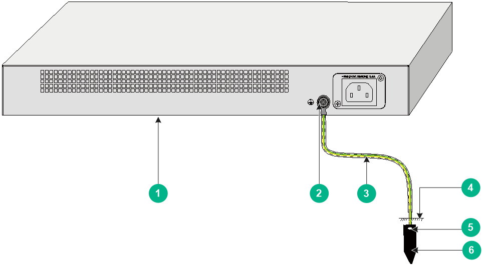
If the installation site does not have grounding strips, but earth ground is available, hammer a 2.5 m (8.20 ft) or longer angle iron or steel tube into the earth ground to serve as a grounding conductor. Make sure a minimum of 0.7 m (2.30 ft) is left between the top of the grounding conductor and the ground. In cold areas, bury the grounding conductor below the frozen soil layer. In areas with thin soil or rocky gravel, determine the depth for burying the grounding conductor based on the actual condition.
If zinc-coated steel is used, the following dimensions requirements must be met:
· Angle iron—A minimum of 50 × 50 × 5 mm (1.97 × 1.97 × 0.20 in).
· Steel tube—A minimum of 3.5 mm (0.14 in) in thickness.
· Flat steel—A minimum of 40 × 4 mm (1.57 × 0.16 in).
· Round steel—A minimum of 10 mm (0.39 in).
Weld the yellow-green grounding cable to the angel iron or steel tube and treat the joint for corrosion protection.
Figure3-2 Grounding the switch by burying the grounding body into the earth
|
(1) Device (rear panel) |
(2) Grounding screw on the device |
(3) Grounding wire |
|
(4) Ground |
(5) Weld point |
(6) Grounding conductor |
Grounding the switch by using an AC power cord
If the installation site does not have grounding strips or earth ground, for example, in a corridor or office, ground an AC-powered switch through the PE wire of the power cord. Make sure the following requirements are met:
· The power cord has a PE wire.
· The ground contact in the power outlet is securely connected to the ground in the power distribution room or on the AC transformer side. If the ground contact in the power outlet is not connected to the ground, report the issue and reconstruct the grounding system.
· The PE terminal for the device is securely connected to the PE wire of the AC power cord.
Figure3-3 Grounding through an AC PE wire

|
(2) Three-wire AC power input cable |
|
|
NOTE: The power connector of a power cord might vary in different countries or regions. This method is applicable only if the power cord has a PE wire. |
Resistance
Make sure the grounding resistance of the grounding strip is less than 1 ohm and that of the angle iron in the ground is less than 10 ohm. For locations with high soil resistivity, sprinkle some resistance reducer to reduce soil resistivity or replace soil around the grounding strip with soil with lower resistance. For measurement of the grounding resistance, see "Appendix Measurement of grounding resistance."
4 Cable routing
General requirements
Cables might be routed indoors or outdoors depending on the device installation location. Read the outdoor or indoor cable routing guidelines carefully before routing the cables.
|
|
CAUTION: · To minimize damage caused by induced lightning strokes, route telecommunication cables such as Ethernet cables indoors whenever possible. · To avoid damage caused by lightning strokes, do not route AC power cords from outdoors for a device for indoor use. · Do not run an Ethernet cable and power cord in parallel. If the cables are damaged, high voltage of the power cord might travel through the network cable to the network port on the device, causing high voltage damage. |
Indoor cable routing
· Route different types of cables separately.
· As a best practice, bind the cables with cable ties at even spacing.
· Make sure the grounding cable is as short and thick as possible. When you connect a grounding cable to a grounding strip, use a screw to fasten the joint tightly or weld the joint and treat it with anti-corrosion measures.
· Keep indoor cables a minimum of 10 cm (3.94 in) away from outdoor cables.
Outdoor cable routing
· If a cable cannot be routed completely indoors, lay the outdoor part of the cable underground. If part of the cable cannot be laid underground but is routed overhead, feed the cable through a metal tube 15 m (49.21 ft) before leading it indoors. Ground the two ends of the metal pipe reliably and install a power or signal lightning arrester for the target interface on the device.
· If you use a shielded cable, make sure the shielding layer makes good contact with the device metal cover at the connection point and install a power or signal lightning arrester for the target interface.
· If you connect outdoor cables without any protection to the device, install a power or signal lightning arrester for the target interface.
Routing power cords
Connect one end of a power cord to the device and the other end to the power strip. Fold the excess part of the power cord into an S-shape and attach it to the inside panel of the rack. Keep power cords a minimum of 5 cm (1.97 in) away from other cables.
Routing signal cables
Install and bundle outdoor and indoor signal cables separately and route them from different outlets on the rack.
Routing fibers
|
|
CAUTION: A fiber is not conductive and does not transmit overvoltage. However, an optical fiber with reinforcing metal stiffener (for example, a metallic armored fiber) transmits overvoltage. You must ground optical fibers with reinforcing metal stiffener from outdoors on an optical distribution frame (ODF) or fiber splice enclosure. |
To connect optical fibers from fiber ports to fiber-copper converters, hang the fibers on the inside panel of the rack. To connect optical fibers to other devices, feed the fibers through PVC pipes. Do not pull and stretch the fibers.
Routing grounding cables
|
|
IMPORTANT: · Before you connect a grounding cable, determine the connection distance in case the cable is too long or too short. · After you complete connecting cables, you can use firestop sealant to fill up the extra space in the outlets. |
Connect one end of a grounding cable to the grounding terminal on the device and the other end to the grounding strip. Keep the grounding cable a minimum of 5 cm (1.97 in) away from signal cables.
5 Equipotential bonding
About equipotential bonding
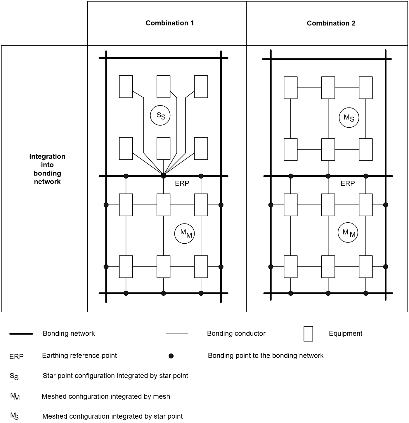
To reach the same or similar potential between interconnected devices in the same physical space such as a cabinet or equipment room, all conductive parts and the protective grounding strip and the grounding terminals of lightning arresters must be connected to the bonding network in start (S), meshed (M), or S and M combined configuration at the shortest possible distance. Conductive parts include metal covers of devices, rack, cabinet, metal tubes, metal cable trays, and metal sheath of shielded cables.
Figure5-1 Basic bonding network connection configurations

Figure5-2 Combined bonding network connection configurations
Restrictions and guidelines
· Use yellow and green cables with a minimum cross-sectional area of 6 mm2 (0.0093 sq in) for equipotential bonding.
· Use cables for equipotential bonding as short as possible.
· Prepare a grounding strip (ring) to act as the bonding bar.
Equipotential bonding connection
Connect the interconnected devices as shown in Figure5-3 for equipotential bonding. After you finish the connection, use a multimeter to test each connection point to ensure good contact and ensure that the resistance is less than 0.1 ohm.
Figure5-3 Equipotential bonding connection
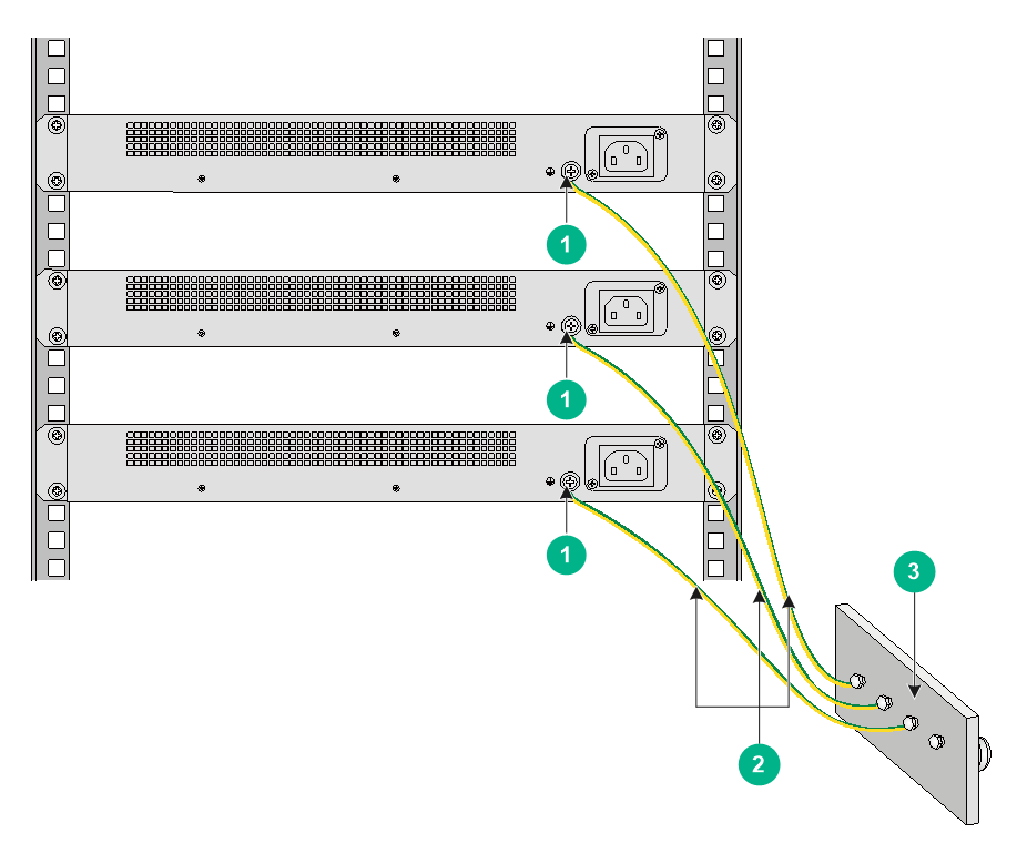
|
(1) Grounding terminal |
(2) Grounding cable |
(3) Grounding strip |
6 Installing lightning arresters
Installing a power lightning arrester
About power lightning arresters
|
CAUTION: · For a country or region such as the European Union that require CE marking on a power lighting arrester, use a power lighting arrester that has a CE marking. · Before installing a power lightning arrester, read the manual provided with it carefully. The manual typically contains the technical parameters and the maintenance and installation instructions for the lightning arrester. |
No power lightning arrester is shipped with a device. Prepare one for the device as required.
If an AC power cord is routed from outdoors, connect the AC power cord first to a power lightning arrester before leading it to the AC power port on the device. After a power lightning arrester is installed, the AC power runs first through the arrester and then to the device.
As a best practice, use a power lighting arrester with a nominal discharge current of 20 kA (8/20 us) or above, and make sure the total length of the power cord from the power lighting arrester to the power port on the device is not less than 5 m (16.40 ft). The total length includes also the power cord for the power strip if a power strip is used.
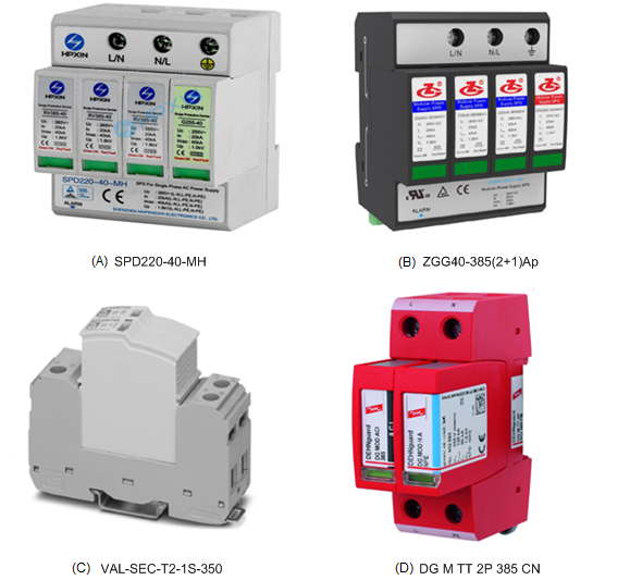
Table6-1 describes four power lighting arresters recommended for your selection.
Table6-1 Recommended power lighting arresters
|
Power lighting arrester model |
Figure |
Manufacturer and website |
|
SPD220-40-MH |
A in Figure6-1 |
Shenzhen Haipengxin Electronics Co., Ltd. http://www.hpxin.com/index.php?lang=en |
|
ZGG40-385(2+1)Ap |
B in Figure6-1 |
Sichuan Zhongguang Lightning Protection Technologies Co., Ltd. http://www.zhongguang.com/en |
|
VAL-SEC-T2-1S-350 |
C in Figure6-1 |
Phoenix Contact http://www.phoenixcontact.com/online/portal/pc |
|
DG M TT 2P 385 CN |
D in Figure6-1 |
DEHN http://www. dehn-international.com/en |
For an SPD220-40-MH or ZGG40-385(2+1)Ap power lighting arrester, you can connect the live line (L) of the power cord to the neutral terminal (N) of the lighting arrester and the neutral line (N) of the power cord to the live terminal (L) of the lighting arrester. These connections are not allowed on a VAL-SEC-T2-1S-350 or DG M TT 2P 385 CN lighting arrester. You can use a testing tool to test whether these connections exist.
Figure6-1 Recommended power lighting arresters
Restrictions and guidelines
· To use a power lightning arrester, make sure its PE terminal is grounded reliably and the grounding cable does not exceed 0.5 m (1.64 ft) and has a minimum cross-sectional area of 6 mm2 (0.0093 in2)
· If a VAL-SEC-T2-1S-350 or DG M TT 2P 385 CN lightning arrester is used, never connect the live line (L) of the power cord to the neutral terminal (N) of the lighting arrester. This might cause malfunction of the lighting arrester and even results in fire accidents.
· Observe the status indicator on the front panel of the power lightning arrester regularly. The power lightning arrester is operating correctly if the indicator is green. If the indicator is red, the arrester is faulty. You must replace it in time.
Installation tools
The following tools are required for power lightning arrester installation.
· Flathead or Phillips screwdriver
· Multimeter
· Diagonal pliers
Procedure
1. Mount the power lightning arrester on the 35 mm (1.38 in) DIN rail in the rack, as shown in Figure6-2.
2. Use a grounding cable to connect the PE terminal of the power lightning arrester to the grounding strip on the rack and use a screwdriver to fasten the connections.
3. Use a multimeter to measure whether the grounding cable of the power lightning arrester is in good contact with the grounding strip on the rack. Make sure the resistance between the lightning arrester and the grounding strip is less than 0.1 ohm.
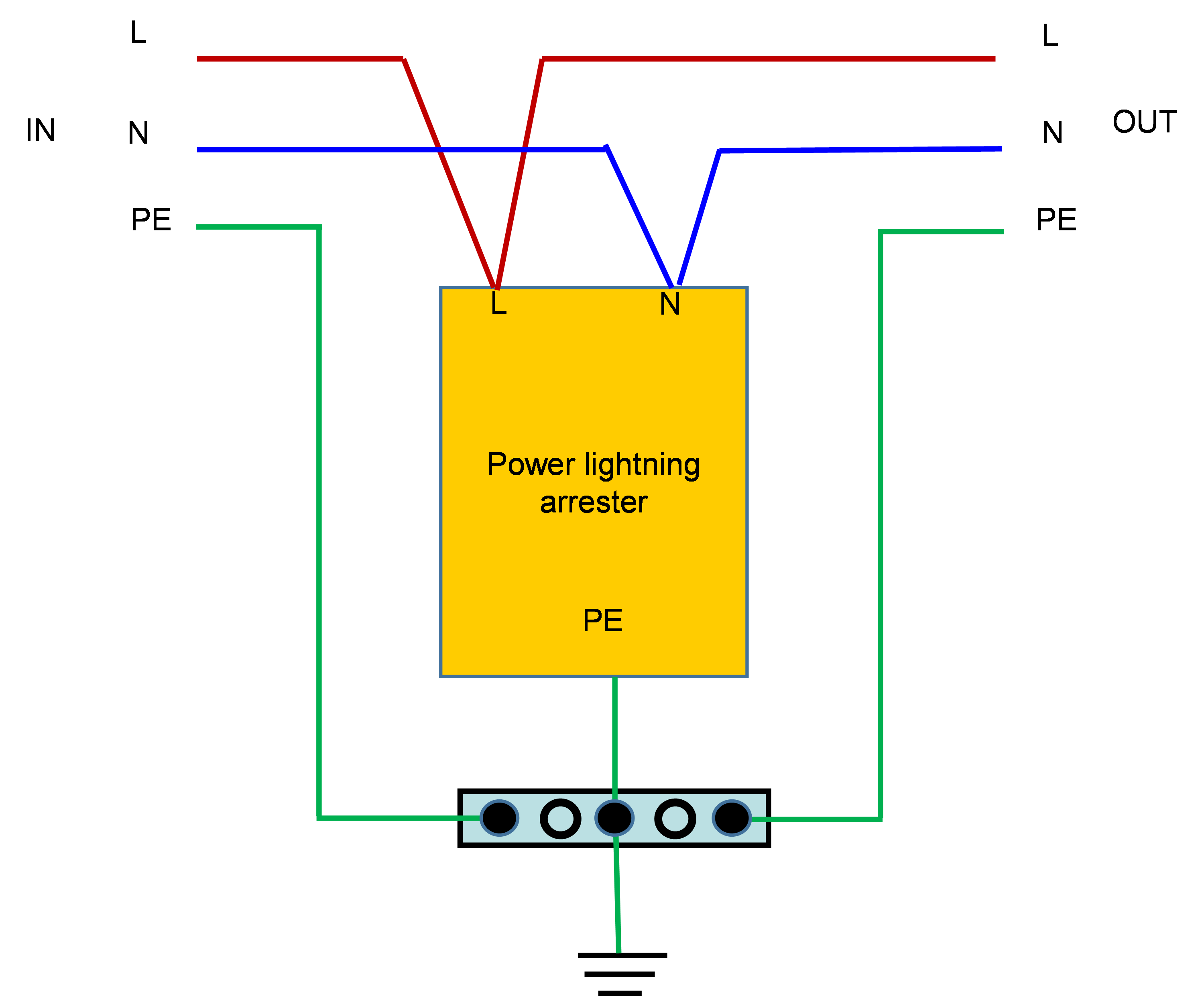
4. Connect the L and N wires of the power cord from the power source to the L terminal and N terminal of the power lighting arrester, respectively. Then connect the L and N wires of the power cord for the device to the L terminal and N terminal of the power lighting arrester, respectively. Use a screwdriver to fasten the connections.
Figure6-2 Mounting a power lightning arrester on a 35 mm (1.38 in) DIN rail
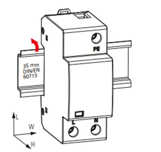
Figure6-3 Power lighting arrester wire connections
Installing a signal lightning arrester
|
|
CAUTION: · Before you install a signal lightning arrester, read the manual provided with it carefully. The manual typically contains the technical parameters and maintenance and installation guidelines for the signal lightning arrester. · CE marking is not required for signal lightning arresters. |
About signal lightning arresters
No signal lightning arresters are provided with a device. Prepare them yourself as required.
If a network cable is routed from outdoors, connect it first to a signal lightning arrester with a nominal discharge current of 3 kA (8/20 us) or above before leading it to the target port on the device. This will protect the device from possible damages caused by lightning strokes.
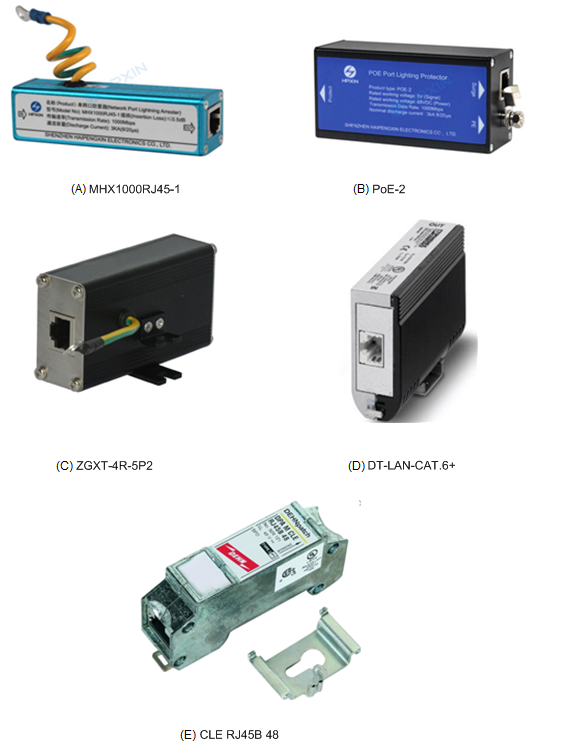
Table6-2 describes the signal lighting arresters recommended for your selection.
Table6-2 Recommended signal lighting arresters
|
Signal lighting arrester model |
Figure |
Description |
Manufacturer and website |
|
MHX1000RJ45-1 |
A in Figure6-4 |
Applicable to 1000 Mbps Ethernet port Not supported for PoE |
Shenzhen Haipengxin Electronics Co., Ltd. http://www.hpxin.com/index.php?lang=en |
|
PoE-2 |
B in Figure6-4 |
Applicable to 1000 Mbps Ethernet port Supported for PoE |
Shenzhen Haipengxin Electronics Co., Ltd. http://www.hpxin.com/index.php?lang=en |
|
ZGXT-4R-5P2 |
C in Figure6-4 |
Applicable to 1000 Mbps Ethernet port Supported for PoE |
Sichuan Zhongguang Lightning Protection Technologies Co., Ltd. http://www.zhongguang.com/en |
|
DT-LAN-CAT.6+ |
D in Figure6-4 |
Applicable to 10 Gbps Ethernet port Supported for PoE |
Phoenix Contact http://www.phoenixcontact.com/online/portal/pc |
|
CLE RJ45B 48 |
E in Figure6-4 |
Applicable to 1000 Mbps Ethernet port Supported for PoE |
DEHN http://www. dehn-international.com/en |
Figure6-4 Recommended signal lighting arresters
Required tools
The following tools are required for signal lightning arrester installation.
· Flathead or Phillips screwdriver
· Multimeter
· Diagonal pliers
Restrictions and guidelines
When installing a signal lightning arrester, identify its IN/Surge end and OUT/Protect end. Make sure you connect the network cable from outdoors to the IN/Surge end, and connect the OUT/Protect end to the protected device.
Connect the grounding cable for the signal lightning arrester to the grounding terminal on the device and make sure the grounding cable does not exceed 0.2 m (0.66 ft). If a number of signal lightning arresters are used, and the grounding terminals on the device are not sufficient, connect the grounding cables for the arresters to the grounding strip for the rack, and make sure the grounding cables do not exceed 0.5 m (1.64 ft).
Make sure the grounding cable has a minimum cross-sectional area of 1.5 mm2 (0.0023 in2)
If the device has more than one network port connected with cables routed from outdoors, install a signal lightning arrester for each network port.
Installation procedure (method 1)
1. Place the signal lightning arrester as close to the grounding terminal on the device as possible.
2. Measure the distance between the arrester and the grounding terminal on the device, cut the ground wire of the arrester to a length as required, and securely fasten the ground wire to the grounding terminal on the device.
3. Use the multimeter to verify that the ground wire of the arrester makes good contact with the grounding terminal on the device. Make sure the resistance between the grounding point of the lightning arrester and the grounding terminal on the device is less than 0.1 ohm.
4. Insert the outdoor network cable into the arrester's IN/Surge end, and the cable connected to the switch into the OUT/Protect end, and observe the LEDs on the lightning arrester to verify that the connection is correct.
5. Use nylon ties to bundle the cables neatly.
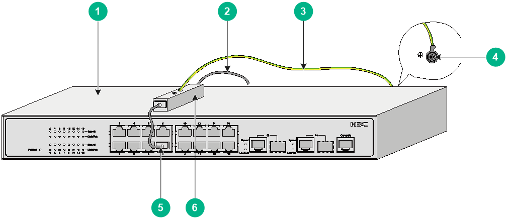
Figure6-5 Installing a signal lightning arrester (method 1)
|
(1) Device (Ethernet switch) |
(2) Cable routed from outdoors |
(3) Equipotential bonding wire |
|
(4) Grounding terminal on the device |
(5) Ethernet cable |
(6) Signal lightning arrester |
Installation procedure (method 2)
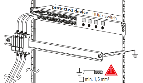
Signal lightning arresters D and E listed in Figure6-4 can be mounted on a 35 mm (1.38 in) DIN rail and grounded reliably through the DIN rail, as shown in Figure6-6.
Figure6-6 Installing a signal lightning arrester (method 2)
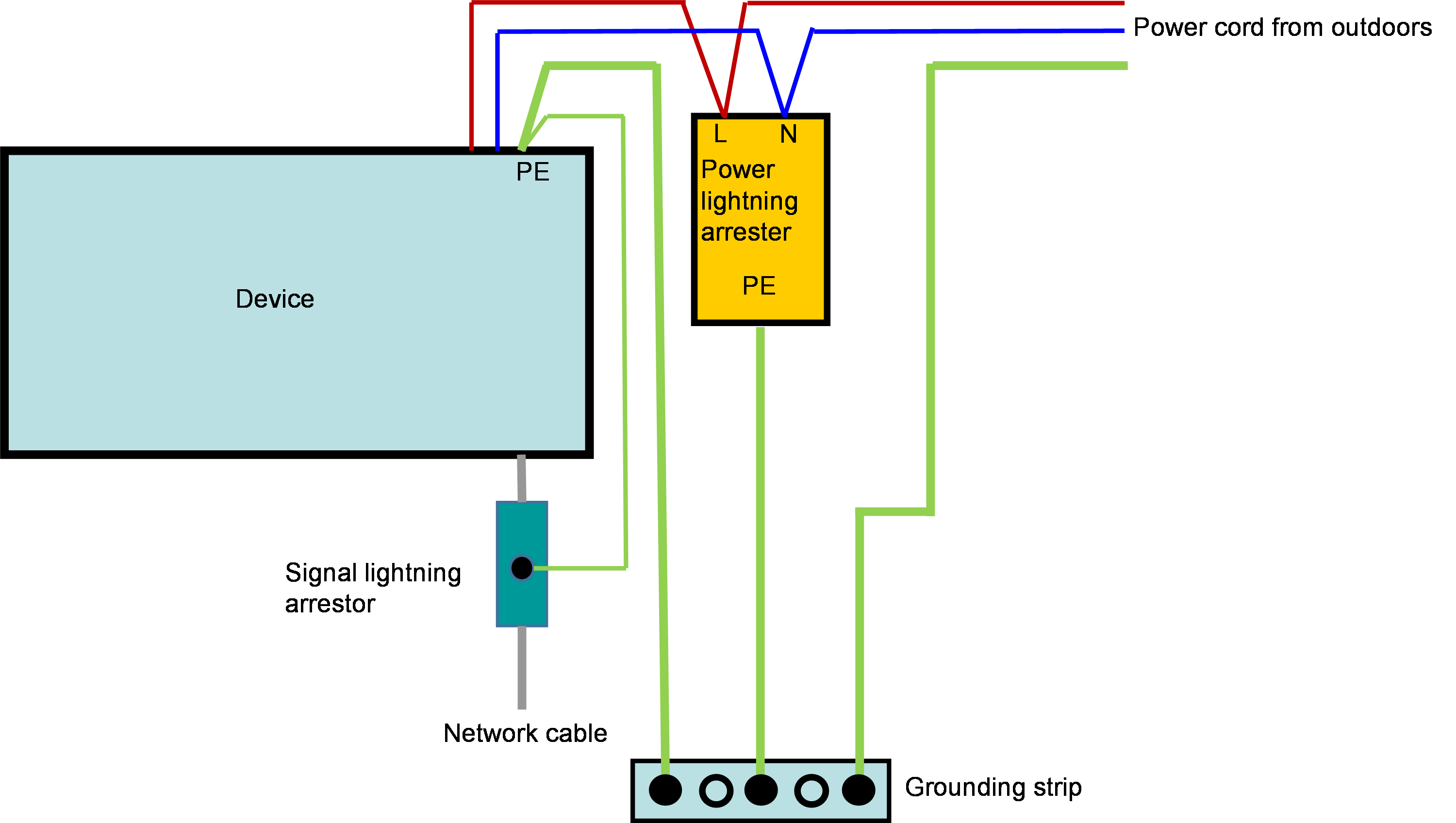
Lightning arrester installation example
Figure6-7 Lightning arrester installation example
7 Installing the lightning protection system in a wiring closet
Lightning protection installation in a wiring closet
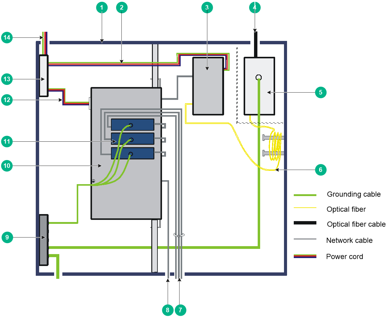
You can place a switch, fiber splice enclosure, and fiber-copper converter in a wiring closet. Place the devices in the wiring closet based on the data flow direction: uplink fibers, fiber splice enclosure, fiber-copper converter, switch, and user. Avoid intertwining the cables.
Figure7-1 Wiring closet lightning protection system installation
|
(1) Wiring closet |
Metal closet that contains the devices to be protected. |
|
(2) Power cord for the fiber-copper converter |
Connects the fiber-copper converter and the power lighting arrester. |
|
(3) Fiber-copper converter |
Optional. If the device supports SFP transceiver modules, you are not required to order the fiber-copper converter separately. |
|
(4) Fiber cable with metal-shielded fiber core |
Routes a fiber cable outdoors from the fiber cable outlet and connects it to an uplink device. To protect fiber cables from environmental affects, use fiber cables with metal-shielded fiber core. |
|
(5) Fiber splice enclosure |
Optional. It fuses fibers and fiber patch cords. |
|
(6) Fiber |
If the fiber in the wiring closet is too long, wrap and fix the fiber. Wrap the fiber with a large radius. |
|
(7) Cables to route outdoors |
Bundle the cables neatly and rout them through the outlet to the outdoors. |
|
(8) Cables to route indoors |
Bundle and outlet the indoor cables separately from the outdoor cables. |
|
(9) Grounding strip for the wiring closet |
Used to ground the devices and protect the devices from lightning strokes. |
|
(10) Protected device |
Ethernet switch. |
|
(11) Signal lightning arrester |
Install a signal lightning arrester for cables laid from outdoors. |
|
(12) Power cord of the device |
Connects the device and the power lightning arrester. |
|
(13) Power lightning arrester |
Use a power lightning arrester for power input at a site where lightning strokes frequently occur or a site with special needs. |
|
(14) Power cord routing from outdoors |
Connects the power source and the power lightning arrester. |
Restrictions and guidelines for lightning protection system installation
Wiring closet
· Install the wiring closet at the first floor to reduce the grounding resistance.
· Install the wiring closet at a dry and ventilated site where there is no sun exposure.
· In areas where lightning strokes frequently occur, do not pole-mount a device or install the device on an outdoor wall. If you have to install the device outdoors, install lighting arresters for the device to minimize the damage caused by lightning strokes. For installation of lighting arresters, see "Installing lightning arresters."
Protected device
· Connect the grounding terminal on the real panel of the device to the grounding strip in the wiring closet.
· The power of the device is led in through the power lightning arrester or common strip in the wiring closet. Make sure the strip is reliably grounded.
Fiber-copper converter
· Secure the fiber-copper converter in the wiring closet. Do not intertwine the network cables and the power cords.
· Lead the power of the fiber-copper converter in through the power lightning arrester or common strip in the wiring closet. Make sure the strip is reliably grounded.
Fiber cable and fiber splice enclosure
· Lay the uplink fiber underground before you lead it into the wiring closet, and connect it to the fiber splice enclosure.
· If you have to lay the fiber cable overhead, isolate the fiber splice enclosure from the wiring closet. You can use a PVC gasket or dielectric frame to isolate the fiber splice enclosure from the wiring closet and make sure the fiber splice enclosure is a minimum of 10 cm (3.94 in) away from the wiring closet and other devices. If you cannot totally separate them, use a buffered optical fiber, for example, a metallic armored fiber. Feed the buffered optical fiber through a multi-strand copper ground wire with a minimum cross-section area of 16 mm2 (0.0248 sq in), and connect it to the grounding strip.
Signal lightning arrester
· Add a signal lightning arrester with a nominal discharge current of 3 kA(8/20 us) or above for an outdoor wiring cable and a cable connected to the outdoor devices.
· Connect the grounding cable for the signal lightning arrester directly to the grounding terminal on the device. If a number of single-port signal lightning arresters are used, and the grounding terminals on the device are not sufficient for single-port signal lightning arresters, connect the grounding cables for the arresters directly to the grounding strip in the wiring closet. Make sure the grounding cables are as short and thick as possible.
Power supply
· Do not connect a power cord from the power grid directly to the device. Use the power from the distribution boxes in the corridor.
· To protect the device from damages caused by lightning strokes, install a power lightning arrester for the power port if the AC power cord is routed from outdoors. As a best practice, use a power lightning arrester with a nominal discharge current of 20 kA (8/20 us) or above.
· Ensure reliable PE connection at the power inlets.
Grounding strip in the wiring closet
· Add a grounding strip for the wiring closet that does not have a grounding strip.
· If you cannot add a grounding strip for the wiring closet, make sure all devices in the wiring closet are equipotentially bonded and are connected finally to the outdoor earth.
Post-installation check
To ensure correct operation of a device after its installation, check the following items before powering it on:
· The grounding cable is connected correctly and reliably.
· The indoor and outdoor cables are installed and bundled separately.
· The power cords, grounding cables, and signal cables are a minimum of 5 cm (1.97 in) away from each other.
· The optical fiber with reinforcing stiffener routed from outdoors is grounded reliably on the ODF or fiber splice enclosure.
· The interconnected devices in the same physical space or area are all equipotentially bonded. For example, all conductive parts including the metal covers of devices, cabinets, racks, metal tubes, cable trays, metal sheath of shielded cables, as well as protective grounding strips and surge arrester grounding terminals in the equipment room are all connected to the equipotential bonding network. Use a multimeter to measure the resistance between the grounding terminal of each device and the grounding point. Make sure the resistance reading is less than 0.1 ohm.
· If an AC power cord is routed from outdoors, make sure a power lightning arrester with a suitable discharge current is installed for the AC power port, and the power cord length from the arrester to the power input port on the device is not less than 5 m (16.40 ft).
· If a network cable is routed from outdoors, make sure a signal lightning arrester with suitable discharge current is installed for the target interface, and the input and output connections of the arrester are correct.
· The grounding cables for the power and signal lightning arresters are corrected correctly and reliably. Use a multimeter to measure the resistance between the grounding point of each lighting arrester and the grounding terminal on the device. Make sure the resistance reading is less than 0.1 ohm.
· Measure and make sure the grounding resistance of the grounding strip to which the devices connect is less than 1 ohm and that of the earth electrode such as an angel iron in the ground is less than 10 ohm.
· The network cables do not run in parallel with power cords.
8 Documentation
· IEC62305-1 Protection against lightning –Part 1: General principles
· IEC62305-2 Protection against lightning –Part 2: Risk management
· IEC62305-3 Protection against lightning –Part 3: Physical damage to structures and life hazard
· IEC62305-4 Protection against lightning – Part 4: Electrical and electronic systems within structures
· IEC 60364-5-54 Electrical installations of buildings – Part 5-54 Selection and erection of electrical equipment – Earthing arrangement, protective conductors and protective bonding conductors
· ITU-T K.27 Bonding configurations and earthing inside a telecommunication building
· ETSI EN 300 253 Environmental Engineering (EE); Earthing and bonding of ICT equipment powered by -48 VDC in telecom and data centers
9 Appendix Measurement of grounding resistance
Grounding resistance is resistance to the flow of electric current from the earth electrode into the earth. A grounding resistance tester can be used for the measurement. You can use the three-point measurement method as described in Figure9-1 or triangle measurement method as described in Figure9-2 to test the grounding resistance for a grounding strip or angle iron in the earth.
Guidelines
Make sure the potential electrode and current electrode are reliably grounded.
Do not measure the grounding resistance immediately after rain.
Three-point measurement
As shown in Figure9-1, place the potential electrode and current electrode as follows:
· Distance between the current electrode and grounding grip d1—Four to five times the maximum diagonal length D of the grounding grid. In this arrangement, potential will be evenly distributed for a distance between the current electrode and the grounding grip.
· Distance between the potential electrode and grounding grip d2—About 50% to 60% of d1.
Move the potential electrode along the connection line between the grounding grid and the current electrode three times, each time moving about 5% of d1. If the resistance values measured are close to each other, the measurement results are valid.
If you cannot place the current electrode at a distance of four to five times of D, set d1 and d2 as follows, depending on the soil resistivity:
· Set d1 to be twice of D and d2 to be the value of D in areas with relatively uniform soil resistivity.
· Set d1 to be three times of D and d2 to be 1.7 times of D in areas with varying soil resistivity.
Figure9-1 Arrangement of electrodes for three-point measurement

Triangle measurement
The potential and current electrodes can also be arranged in a triangle as shown in Figure9-2. Typically you place the electrodes in an arrangement of d2 = d1 ≥ 2d and at an angle about 30°.
Figure9-2 Triangle arrangement of potential electrode and current electrodes

