- Table of Contents
- Related Documents
-
| Title | Size | Download |
|---|---|---|
| 01-Installation Guide | 2.87 MB |
Examining the installation site
Installing the switch in a 19-inch rack
Rack-mounting procedure at a glance
Chassis dimensions and rack requirements
Rack-mounting the switch by using front and rear mounting brackets
Rack-mounting the switch by using front mounting brackets and a rack-mount rail kit
Connecting the grounding cable to the chassis
Grounding the switch by using a grounding strip
Installing and removing a fan tray
Installing and removing a power supply
Connecting the power cord for a PSR450-12A/PSR450-12A1 power supply
Connecting the power cord for a PSR450-12AHD power supply
Connecting the DC power cord for a PSR450-12D power supply
3 Accessing the switch for the first time
Connecting the switch to a configuration terminal
Connecting a DB9-to-RJ45 console cable
4 Maintenance and troubleshooting
Configuration terminal display issues
No display on the configuration terminal
Garbled display on the configuration terminal
1 Preparing for installation
This document is applicable to the following Ethernet switches:
Table1-1 Switch series and models
|
Switch series |
Switch model |
Product code |
|
S6116 switch series |
S6116-48X |
LS-6116-48X |
|
S6116-48X-M |
LS-6116-48X-M |
Safety recommendations
To avoid any equipment damage or bodily injury caused by incorrect use, read the following safety recommendations before installation. Note that the recommendations do not cover every possible hazardous condition.
· Before cleaning the switch, remove all power cords from the switch. Do not clean the switch with wet cloth or liquid.
· Do not place the switch near water or in a damp environment. Prevent water or moisture from entering the switch chassis.
· Do not place the switch on an unstable case or desk. The switch might be severely damaged in case of a fall.
· Ensure good ventilation of the equipment room and keep the air inlet and outlet vents of the switch free of obstruction.
· Connect the yellow-green protection grounding cable before power-on.
· Make sure the operating voltage is in the required range.
· To avoid electrical shocks, do not open the chassis while the switch is operating or when the switch is just powered off.
· When replacing a removable component such as a power supply or fan tray, wear an ESD wrist strap and make sure it makes good skin contact and is reliably grounded.
Examining the installation site
The switch must be used indoors. Mount your switch in a rack and verify the following items:
· Adequate clearance is reserved at the air inlet and outlet vents for ventilation.
· The rack has a good ventilation system.
· Identify the hot aisle and cold aisle at the installation site, and make sure ambient air flows into the switch from the cold aisle and exhausts to the hot aisle.
· Identify the airflow designs of neighboring devices, and prevent hot air flowing out of the bottom device from entering the top device.
· The rack is sturdy enough to support the switch and its accessories.
· The rack is reliably grounded.
To ensure correct operation and long service life of your switch, install it in an environment that meets the requirements described in the following subsections.
Temperature/humidity
Maintain appropriate temperature and humidity in the equipment room.
· Lasting high relative humidity can cause poor insulation, electricity leakage, mechanical property change of materials, and metal corrosion.
· Lasting low relative humidity can cause washer contraction and ESD and cause problems including loose screws and circuit failure.
· High temperature can accelerate the aging of insulation materials and significantly lower the reliability and lifespan of the switch.
For the temperature and humidity requirements of different switch models, see H3C S6116 Ultra-Low Latency Switch Series Hardware Information and Specifications.
Cleanliness
Dust buildup on the chassis might cause electrostatic adsorption and dust corrosion, resulting in poor contact of metal connectors and contact points. This might shorten the device's lifetime and even cause device failure in the worst case. Table1-2 describes the switch requirement for cleanliness.
Table1-2 Switch requirement for cleanliness
|
Substance |
Particle diameter |
Concentration limit |
|
Dust particles |
≥ 0.5 µm |
≤ 1.8 × 10⁷ particles/m3 |
To maintain cleanliness in the equipment room, follow these guidelines:
· Keep the equipment room away from pollution sources. Do not smoke, eat, or drink in the equipment room.
· Use double-layer glass in windows and seal doors and windows with dust-proof rubber strips. Use screen doors and window screens for doors and windows open to the outside and make sure the external windows are air tight.
· Use dustproof materials for floors, walls, and ceilings and use wallpaper or matt paint that does not produce powders.
· Clean the equipment room regularly and clean the air filters of the rack each month.
· Wear ESD clothing and shoe covers before entering the equipment room, keep the ESD clothing and shoe covers clean, and change them frequently.
Corrosive gas limit
Corrosive gases can accelerate corrosion and aging of metal components. Make sure the corrosive gases do not exceed the concentration limits as shown in Table1-3.
Table1-3 Corrosive gas concentration limits
|
Gas |
Average concentration (mg/m3) |
Maximum concentration (mg/m3) |
|
SO2 |
0.3 |
1.0 |
|
H2S |
0.1 |
0.5 |
|
Cl2 |
0.1 |
0.3 |
|
HCI |
0.1 |
0.5 |
|
HF |
0.01 |
0.03 |
|
NH3 |
1.0 |
3.0 |
|
O3 |
0.05 |
0.1 |
|
NOX |
0.5 |
1.0 |
|
|
CAUTION: As a best practice, control the corrosive gas concentrations in the equipment room at their average values. Make sure the corrosive gas concentrations do not exceed 30 minutes per day at their maximum values. |
To control corrosive gases, use the following guidelines:
· As a best practice, do not build the equipment room in a place with a high concentration of corrosive gases.
· Make sure the equipment room is not connected to sewer, vertical shaft, or septic tank pipelines and keep it far away from these pipelines. The air inlet of the equipment room must be away from such pollution sources.
· Use environmentally friendly materials to decorate the equipment room. Avoid using organic materials that contains harmful gases, such as sulfur or chlorine-containing insulation cottons, rubber mats, sound-proof cottons, and avoid using plasterboards with high sulfur concentration.
· Place fuel (diesel or gasoline) engines separately. Do not place them in the same equipment room with the device. Make sure the exhausted air of the engines will not flow into the equipment room or towards the air inlet of the air conditioners.
· Place batteries separately. Do not place them in the same room with the device.
· Employ a professional company to monitor and control corrosive gases in the equipment room regularly.
EMI
All electromagnetic interference (EMI) sources, from outside or inside of the switch and application system, adversely affect the switch in the following ways:
· A conduction pattern of capacitance coupling.
· Inductance coupling.
· Electromagnetic wave radiation.
· Common impedance (including the grounding system) coupling.
To prevent EMI, use the following guidelines:
· If AC power is used, use a single-phase three-wire power receptacle with protection earth (PE) to filter interference from the power grid.
· Keep the switch far away from radio transmitting stations, radar stations, and high-frequency devices.
· Use electromagnetic shielding, for example, shielded interface cables, when necessary.
· To prevent signal ports from getting damaged by overvoltage or overcurrent caused by lightning strikes, route interface cables only indoors.
Laser safety
|
|
WARNING! · The switch is a Class 1M laser device. · Disconnected optical fibers or transceiver modules might emit invisible laser light. Do not stare into beams or view directly with optical instruments when the switch is operating. |
Installation tools
No installation tools are provided with the switch. Prepare the following tools yourself:
· Phillips screwdriver.
· Flat-head screwdriver.
· ESD wrist strap.
· Marker.
Installation accessories
Before installation, make sure you have all the required installation accessories. If any accessory is damaged or missing, use the part No. provided in this table to purchase a new one.
Table1-4 Installation accessories
|
Part No. |
Description |
Quantity |
Applicable device models |
|
2150A03X |
Front mounting bracket kit
|
1 kit, provided (If the mounting bracket has a small round role, you can use the hole to hang the asset tag.) |
All S6116 models |
|
2150A0BP |
Rear mounting kit, including a pair of rear mounting brackets and two shoulder screws
|
1 kit, provided |
All S6116 models |
|
2150A050 |
1U rack mounting rail kit A (including long slide rails and chassis rails)
|
Optional |
All S6116 models |
|
2150A0CP |
1U rack mounting rail kit B (including super-short slide rails and chassis rails)
|
Optional |
All S6116 models |
|
N/A |
M6 screw and cage nut
|
User supplied |
All S6116 models |
|
0404A1TR |
Grounding cable
|
1, provided |
All S6116 models |
|
N/A |
Grounding screw
|
1, provided |
All S6116 models |
|
2114A09C |
Power supply filler panel
|
1, provided |
All S6116 models |
|
N/A |
Releasable cable tie
|
User supplied |
All S6116 models |
|
04042967 |
Serial console cable
|
Optional |
All S6116 models |
|
14990101 |
SFP port plug
|
Same number as the SFP+ ports |
All S6116 models |


2 Installing the switch
|
|
CAUTION: Keep the tamper-proof seal on a mounting screw on the chassis cover intact, and if you want to open the chassis, contact H3C for permission. Otherwise, H3C shall not be liable for any consequence caused thereby. |
|
|
CAUTION: Always wear an ESD wrist strap during the installation process. Make sure the wrist strap makes good skin contact and is reliably grounded. |
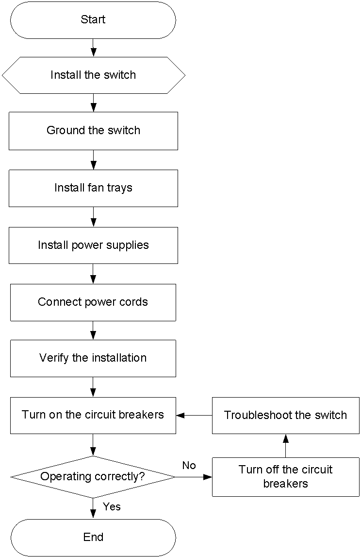
Figure2-1 Hardware installation flow
Installing the switch in a 19-inch rack
Installation accessories
Table2-2 Installation accessories
|
Front mounting brackets |
Rear mounting brackets or rack mounting rail kit |
|
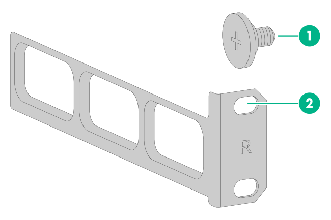
1U high, one pair (provided). See Figure2-2. (If the mounting bracket has a small round role, you can use the hole to hang the asset tag.) |
· 1U rear mounting brackets (provided). See Figure2-3. · 1U rack mounting rail kit A, including one pair of chassis rails and one pair of long slide rails (optional). See Figure2-4. · 1U rack mounting rail kit B, including one pair of chassis rails and one pair of super-short slide rails (optional). See Figure2-5. |

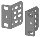
Figure2-3 Rear mounting bracket and shoulder screw
|
(1) Shoulder screw |
(2) Screw hole for attaching the rear mounting bracket to the rack |
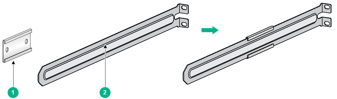
Figure2-4 1U rack mounting rail kit A (long slide rails)
|
(1) Chassis rail |
(2) Long slide rail |
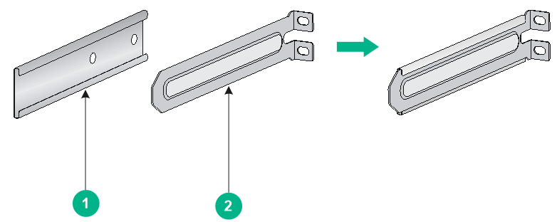
Figure2-5 1U rack mounting rail kit B (super-short slide rails)
|
(1) Chassis rail |
(2) Super-short slide rail |
Rack-mounting procedure at a glance
Figure2-6 Rack-mounting procedure

|
|
NOTE: If a rack shelf is available, you can rack-mount the switch by using the front mounting brackets and rack shelf. Put the switch on the rack shelf, slide the switch to an appropriate location, and then attach the front mounting brackets to the front rack posts. |
Chassis dimensions and rack requirements
The S6116 switches have the same chassis dimensions. This document uses the S6116-48X switch as an example.
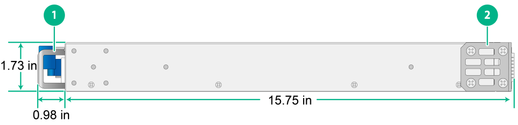
Figure2-7 S6116-48X chassis dimensions with the front mounting brackets installed at the port side
|
(1) Power supply handle |
(2) Front mounting bracket |
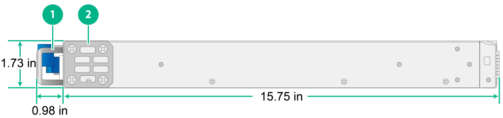
Figure2-8 S6116-48X chassis dimensions with the front mounting brackets installed at the power supply side
|
(1) Power supply handle |
(2) Front mounting bracket |
Follow these guidelines when you install the switch in a 19-inch rack:
· The distance between the front and rear posts of the rack must meet the requirements described in Table2-3.
· To secure the switch to the rack, you must install not only front mounting brackets, but also slide rails or rack-mount rail kit.
|
Chassis dimensions |
Installation method |
Distance between the front and rear rack posts |
Rack depth requirement |
|
· Height—44 mm (1.73 in) (1 RU) · Width—440 mm (17.32 in). · Total depth—425 mm (16.73 in) ¡ 25 mm (0.98 in) for the power supply or fan tray handle ¡ 400 mm (15.75 in) for the chassis. |
Front mounting brackets at the port side Rear mounting brackets with the wide flange inside the rack |
372 to 536 mm (14.65 to 21.10 in) |
To ensure that the rack door can be closed easily after cables are connected, make sure the rack meets the following requirements: · A minimum of 800 mm (31.50 in) in depth (recommended). · A minimum of 130 mm (5.12 in) from the front rack post to the front door. · A minimum of 153 mm (6.02 in) from the rear rack post to the interior side of the rear door. |
|
Front mounting brackets at the power supply side Rear mounting brackets with the wide flange inside the rack |
372 to 507 mm (14.65 to 19.96 in) |
||
|
Front mounting brackets at the port side Rear mounting brackets with the wide flange outside the rack |
214 to 378 mm (8.43 to 14.88 in) |
||
|
Front mounting brackets at the power supply side Rear mounting brackets with the wide flange outside the rack |
214 to 349 mm (8.43 to 13.74 in) |
||
|
Front mounting brackets Rack-mount rail kit with long slide rails |
562 to 793 mm (22.13 to 31.22 in) |
To ensure that the rack door can be closed easily after cables are connected, make sure the rack meets the following requirements: · A minimum of 800 mm (31.50 in) in depth (recommended) · A minimum of 130 mm (5.12 in) from the front rack post to the front door · A minimum of 470 mm (18.50 in) from the front rack post to the rear door |
|
|
Front mounting brackets Rack-mount rail kit with super-short slide rails (narrow-spacing installation) |
397 to 505 mm (15.63 to 19.88 in) |
||
|
Front mounting brackets Rack-mount rail kit with super-short slide rails (wide-spacing installation) |
504 to 612 mm (19.84 to 24.09 in) |
Rack-mounting the switch by using front and rear mounting brackets
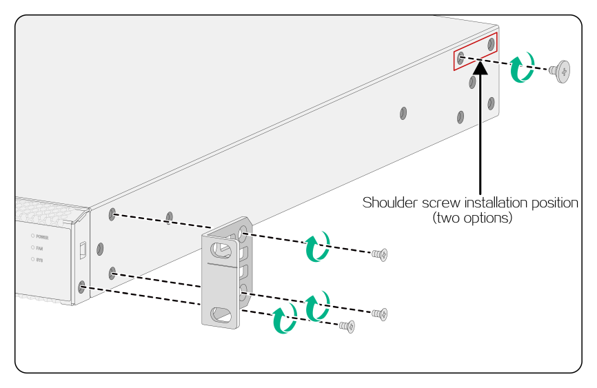
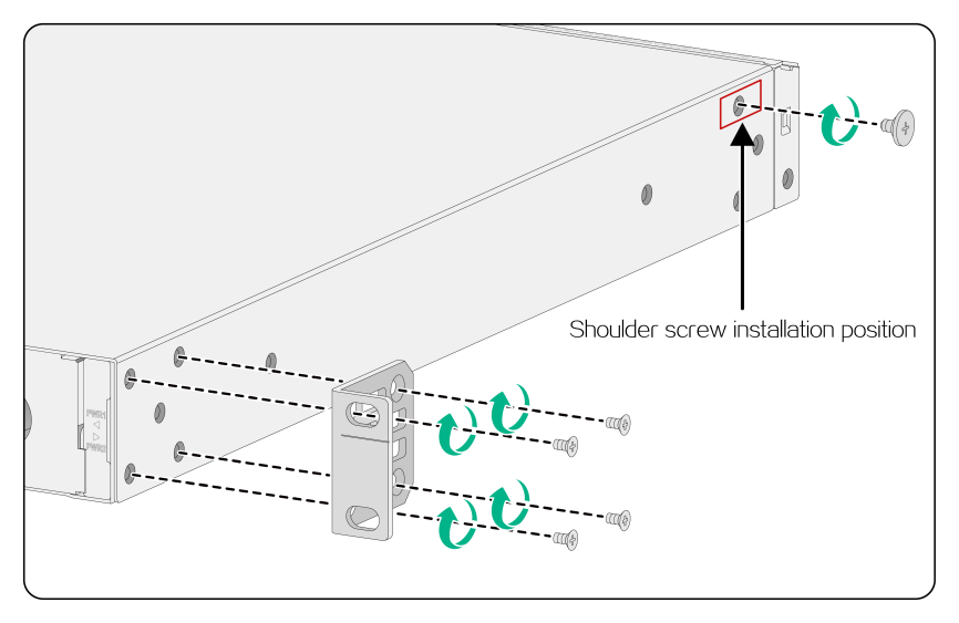
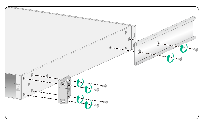
Attaching the front mounting brackets and shoulder screws to the switch
The switch provides two installation positions for front mounting brackets. One is near the port side and the other is near the power supply side. Choose the installation position for the front mounting brackets as required. The screw (mounting bracket screws and shoulder screws) installation method differs slightly for installing the front mounting brackets at the power supply side or port side.
To attach the front mounting brackets and shoulder screws to the switch:
1. Align the holes in the wide flange of one front mounting bracket with the screw holes in a side panel of the chassis. See Figure2-9 and Figure2-10.
2. Use M4 screws (supplied with the switch) to attach the mounting bracket to the chassis.
As a best practice, use a torque of 12 kgf-cm (1.18 Nm) to fasten the M4 screws.
3. Repeat the preceding two steps to attach the other mounting bracket to the chassis.
4. Unpack the shoulder screws and attach them to the chassis. As a best practice, use a torque of 12 kgf-cm (1.18 Nm) to fasten the shoulder screws.
If you install the front mounting brackets at the port side, two installation positions are available for the shoulder screw (red marked in Figure2-9).
If you install the front mounting brackets at the power supply side, one installation position is available for the shoulder screw (red marked in Figure2-10.).
Figure2-9 Attaching the front mounting brackets (port side mounting position) and shoulder screws to the chassis
Attaching the rear mounting brackets to the rack
1. Determine the switch installation position in the rack.
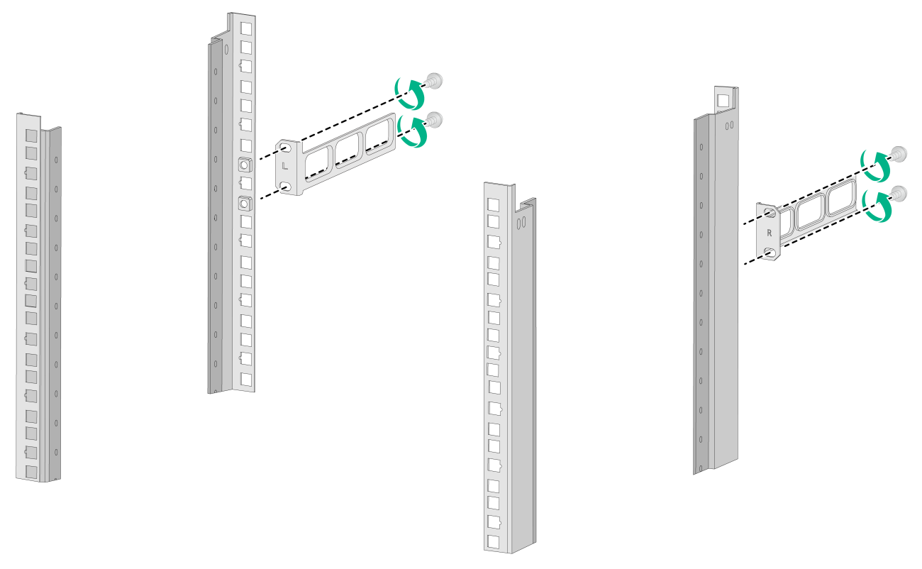
2. Orient the rear mounting brackets with the wide flange inside or outside the rack as required, as shown in Figure2-11 and Figure2-12.
3. Use M6 screws and cage nuts to attach the rear mounting brackets to the rear rack posts. As a best practice, use a torque of 30 kgf-cm (2.94 Nm) to fasten the M6 screws.
Make sure the corresponding cage nuts on the left and right rear rack posts are at the same height.
Do not fully tighten the M6 screws before mounting the switch in the rack.
Figure2-11 Attaching the rear mounting brackets to the rack with the wide flange inside the rack
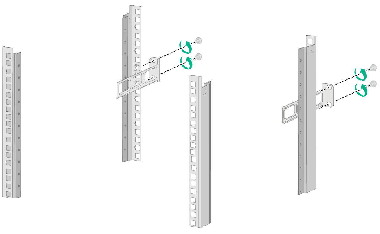
Figure2-12 Attaching the rear mounting brackets to the rack with the wide flange outside the rack
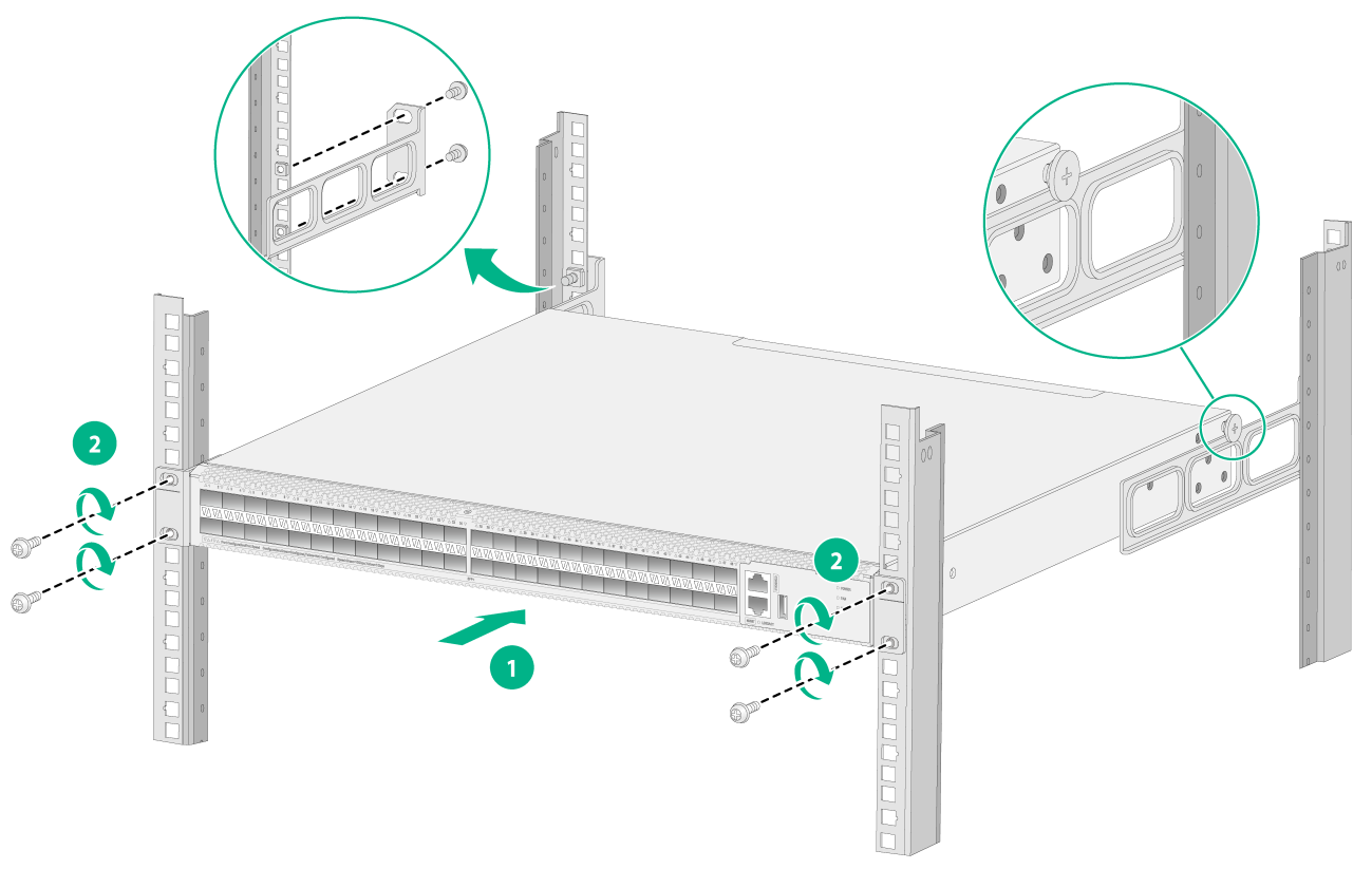
Mounting the switch in the rack
The rack-mounting procedure is the same for the S6116 switches. The following procedure uses the S6116-48X switch as an example.
To mount the switch in the rack:
1. Wear an ESD wrist strap and make sure it makes good skin contact and is reliably grounded.
2. Verify that the front mounting brackets and shoulder screws are securely attached to the two sides of the switch. For more information, see Figure2-9 and Figure2-10.
3. Attach cage nuts (user supplied) to the front rack posts and make sure the corresponding cage nuts on the front and rear rack posts are at the same height.
4. One person supports the chassis bottom and pushes the chassis into the rack. Make sure the shoulder screws rest firmly on the upper edge of the rear mounting brackets. See Figure2-13 and Figure2-14.
5. The other person attaches the front mounting brackets by using M6 screws and cage nuts to the front rack posts. Make sure the switch is installed securely in the rack. See Figure2-13 and Figure2-14. As a best practice, use a torque of 30 kgf-cm (2.94 Nm) to fasten the M6 screws.
Figure2-13 Mounting the switch in the rack (with the wide flange of the rear mounting brackets inside the rack)
Rack-mounting the switch by using front mounting brackets and a rack-mount rail kit
The switch has two front mounting bracket installation positions on its two side panels: one near the network port side and one near the power supply side.
The switch provides a grounding point (with a grounding sign) on the rear panel.
The front mounting bracket installation positions and grounding point position are the same for the S6116 switches. This document uses the S6116-48X switch as an example.
Figure2-15 Front mounting bracket installation positions and grounding point on the S6116-48X switch
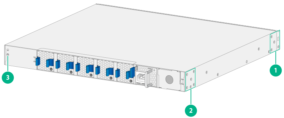
|
(1) Front mounting bracket installation position near the port side |
|
(2) Front mounting bracket installation position near the power supply side |
|
(3) Grounding point |
Attaching the front mounting brackets and chassis rails to the chassis
|
|
IMPORTANT: M4 screws are used to secure the mounting brackets and chassis rails to the switch. As a best practice, use a torque of 12 kgf-cm (1.18 Nm) to fasten M4 screws. |
The method of attaching the front mounting brackets and chassis rails to the chassis is the same for the S6116 switches. This document uses the S6116-48X switch as an example.
To attach the mounting brackets and chassis rails to the chassis:
1. Place the wide flange of a front mounting bracket against a side panel of the chassis and align the round holes in the wide flange of the front mounting bracket with the screw holes in the side panel. Then use M4 screws (provided) to attach the front mounting bracket to the chassis.
¡ To install the front mounting brackets at the port side, see Figure2-16, Figure2-17, and Figure2-18.
¡ To install the front mounting brackets at the power supply side, see Figure2-19, Figure2-20, and Figure2-21.
2. Determine the chassis rail installation position based on the front mounting bracket installation position.
3. Place the chassis rail against the side panel of the chassis and align the installation holes in the chassis rail with rail mounting holes in the chassis. Then use M4 screws (provided) to attach the chassis rail to the chassis.
¡ For installation of chassis rails of rack mounting rail kit A (long slide rails), see Figure2-16 and Figure2-19.
¡ The chassis rails of rack mounting rail kit B (super-short slide rails) support narrow-spacing installation and wide-spacing installation. Select narrow-spacing (as shown in Figure2-17 and Figure2-20) or wide-spacing (as shown in Figure2-18 and Figure2-21) installation based on the distance between the front and rear rack posts.
4. Follow the same procedure to attach another mounting bracket and chassis rail to the opposite chassis side.
Figure2-16 Attaching the front mounting brackets and chassis rails to an S6116-48X switch (front mounting brackets installed near the port side, rack mounting rail kit A)
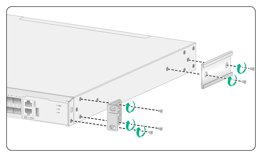
Figure2-17 Attaching the front mounting brackets and chassis rails to an S6116-48X switch (front mounting brackets installed near the port side, rack mounting rail kit B, narrow-spacing installation of chassis rails)
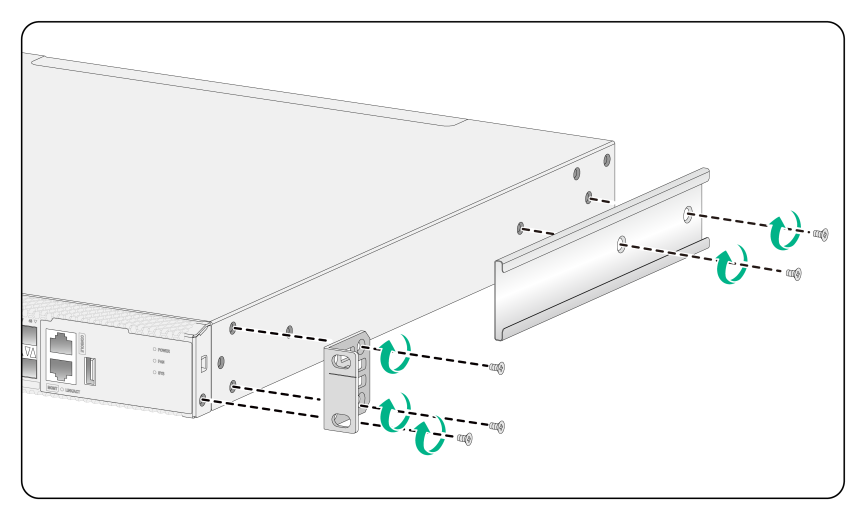
Figure2-18 Attaching the front mounting brackets and chassis rails to an S6116-48X switch (front mounting brackets installed near the port side, rack mounting rail kit B, wide-spacing installation of chassis rails)
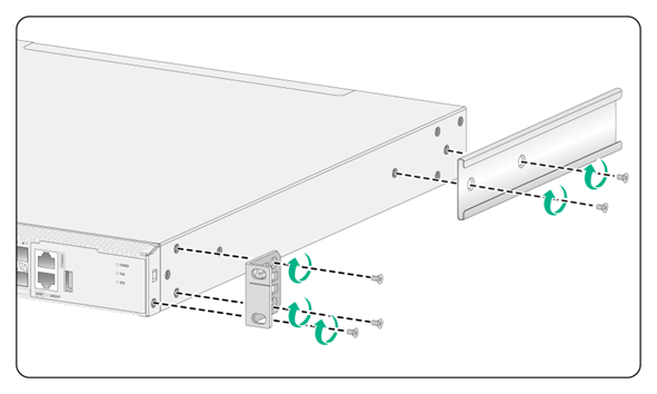
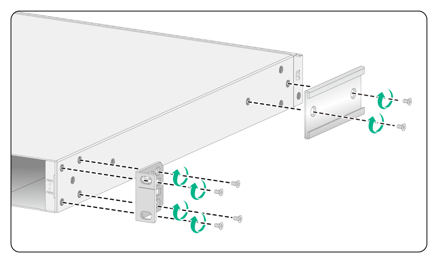
Figure2-20 Attaching the front mounting brackets and chassis rails to an S6116-48X switch (front mounting brackets installed near the power supply side, rack mounting rail kit B, narrow-spacing installation of chassis rails)
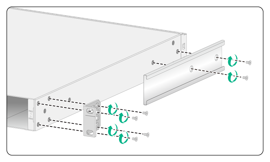
Figure2-21 Attaching the front mounting brackets and chassis rails to an S6116-48X (front mounting brackets installed near the power supply side, rack mounting rail kit B, wide-spacing installation of chassis rails)
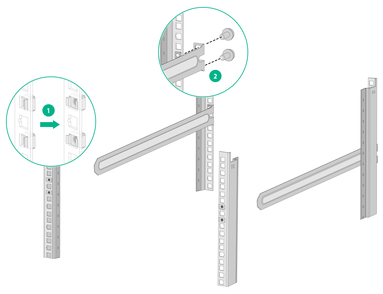
Attaching the long/short slide rails to the rack
|
|
IMPORTANT: M6 screws and cage nuts are used to attach the slide rails to the rack. Prepare M6 screws and cage nuts yourself. As a best practice, use a torque of 30 kgf-cm (2.94 Nm) to fasten the M6 screws. |
Before mounting the switch in the rack, you must attach slide rails to the rack.
The installation procedure is the same for different types of slide rails. The following procedure attaches 1U long slide rails to the rack.
To attach the slide rails to the rack:
1. Identify the slide rail installation position on the rack based on the switch installation position.
2. Install cage nuts (user-supplied) in the mounting holes in the rack posts.
3. Align the screw holes in one slide rail with the cage nuts in a rear rack post, and then use M6 screws (user-supplied) to attach the slide rail to the rack, as shown in Figure2-22.
4. Attach the other slide rail to the rear rack post on the opposite side.
Make sure the two slide rails are at the same height and can slide into the chassis rails smoothly.
Figure2-22 Installing the 1U long slide rails
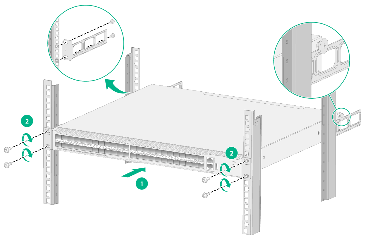
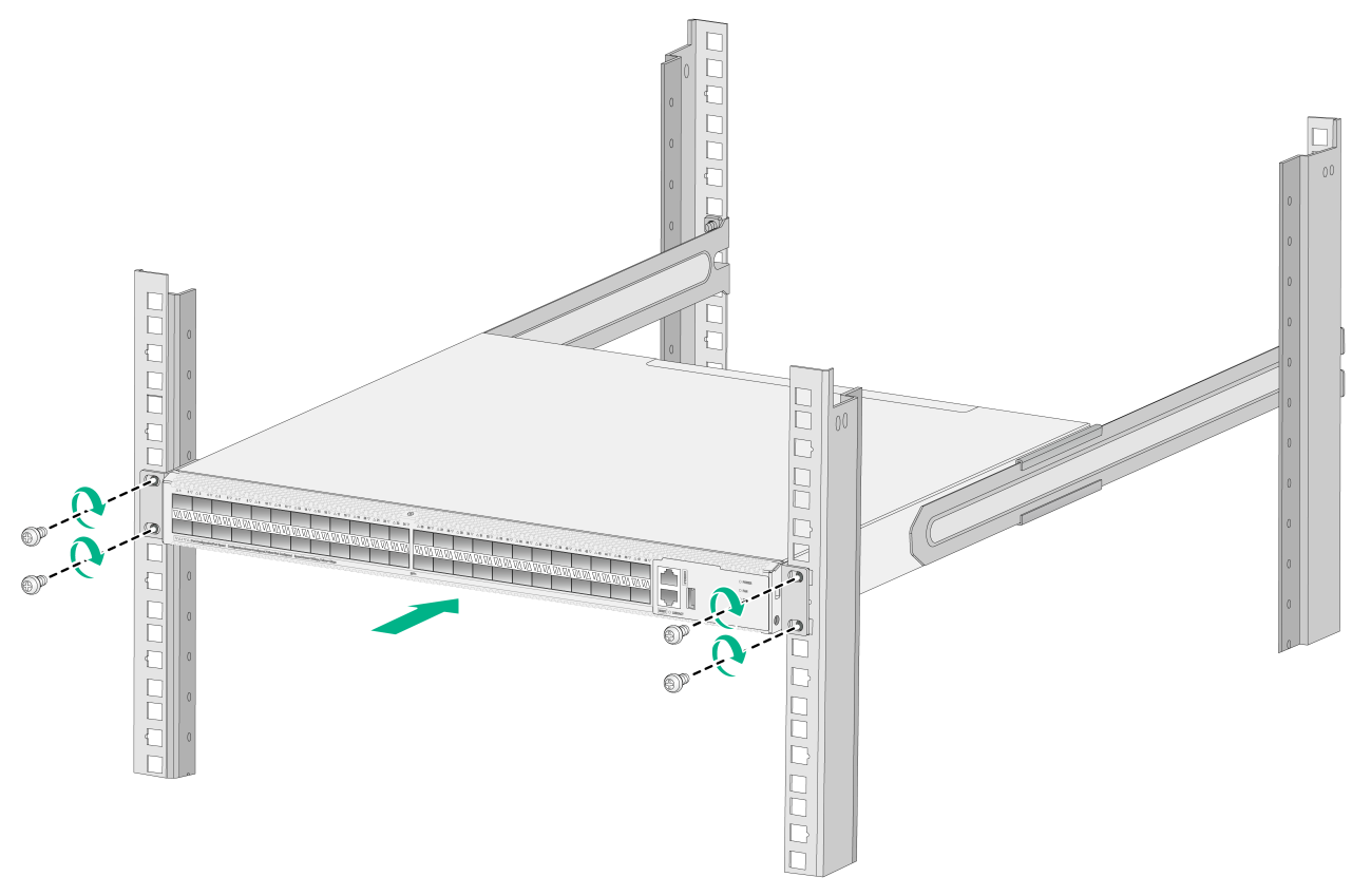
Mounting the switch in the rack
The rack-mounting procedure is the same for the S6116 switches. The following procedure uses the S6116-48X switch as an example.
To mount the switch in the rack:
1. Wear an ESD wrist strap and make sure it makes good skin contact and is reliably grounded.
2. Verify that the front mounting brackets and chassis rails have been securely attached to the switch chassis.
3. Verify that the slide rails have been correctly attached to the rear rack posts.
4. Attach cage nuts (user-supplied) to the front rack posts and make sure they are at the same level as the slide rails.
5. One person performs the following operations:
a. Supporting the bottom of the switch, aligns the chassis rails with the slide rails on the rack posts.
b. Pushes the switch slowly for the slide rails to slide into the chassis rails smoothly until the mounting brackets are flush against the front rack posts.
- For long slide rails of rack mounting rail kit A and slide rails of rack mounting rail kit C, make sure the front ends of the slide rails reach out of the chassis rails.
- For super-short slide rails of rack mounting rail kit B, make sure the slide rails slide a minimum length of 110 mm (4.33 in) into the chassis rails.
6. The other person uses M6 screws (user-supplied, rust-proofed) to attach the mounting brackets to the rack.
As a best practice, use a torque of 30 kgf-cm (2.94 Nm) to fasten the M6 screws.
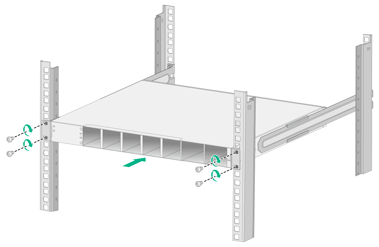
Figure2-24 Mounting an S6116-48X switch in the rack (front mounting brackets installed near the port side)
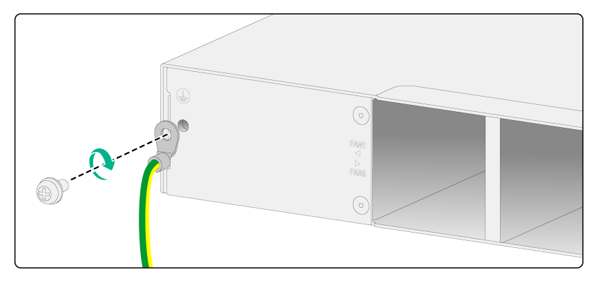
Connecting the grounding cable to the chassis
1. Unpack the grounding cable and grounding screw.
2. Use the grounding screw to attach the single-hole ring terminal of the grounding table to the grounding point and then fasten the screw (clockwise direction), as shown in Figure2-25.
As a best practice, use a torque of 16 kgf-cm (1.57 Nm) to fasten the grounding screws.
Figure2-25 Attaching the grounding cable to the chassis
Grounding the switch by using a grounding strip
|
|
CAUTION: · Correctly connecting the grounding cable is crucial to lightning protection and EMI protection. You must connect the grounding cable correctly and reliably for the switch. · Do not connect the grounding cable to a fire main or lightning rod. · To guarantee the grounding effect and avoid switch damage, use the grounding cable provided with the switch to connect the switch to a grounding strip in the equipment room. |
To ground the switch by using a grounding strip:
1. Make sure one end of the grounding cable has been attached to the switch.
2. Remove the hex nut from a grounding post on the grounding strip.
3. Cut the grounding cable to a length according to the distance between the switch and the grounding strip.
4. Attach a ring terminal to the grounding cable:
a. Strip 5 mm (0.20 in) of insulation off the end of the grounding cable.
b. Slide the heat-shrink tubing onto the cable and insert the bare metal part into the end of the ring terminal.
c. Use a crimping tool to secure the metal part of the cable to the ring terminal.
d. Slide the heat-shrink tubing down the cable until the tube covers the joint.
e. Use a heat gun to shrink the tubing around the cable.
Figure2-26 Attaching a ring terminal to the grounding cable

5. Attach the ring terminal to the grounding post of the grounding strip, and fasten it with the removed hex nut.
Figure2-27 Connecting the grounding cable to a grounding strip
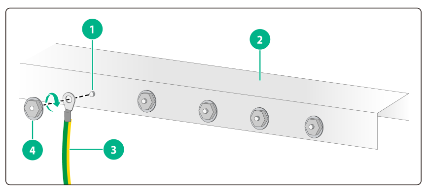
|
(1) Grounding post |
(2) Grounding strip |
|
(3) Grounding cable |
(4) Hex nut |
Installing and removing a fan tray
|
|
CAUTION: · The switch came with empty fan tray slots. For adequate heat dissipation, you must install five fan trays of the same model for the switch. If a fan tray is absent or faulty, the system reports an insufficient fan tray number error. If more than one fan tray is absent or faulty, the device will not start. · Make sure all slots have a module installed when the switch is operating. · If more than one fan tray fails during switch operation, do not remove the failed fan trays simultaneously. Replace the fan trays one by one and finish replacing each fan tray within three minutes. |
Installing a fan tray
|
|
CAUTION: To prevent damage to the fan tray or the connectors on the backplane, insert the fan tray gently. If you encounter a hard resistance while inserting the fan tray, pull out the fan tray and insert it again. |
Select fan trays for the switch as needed. For the fan trays available for the switch and their specifications, see H3C S6116 Ultra-Low Latency Switch Series Hardware Information and Specifications.
The procedure of installing fan trays is the same for the S6116 switches. This section uses the S6116-48X switch as an example to describe how to install a fan tray.
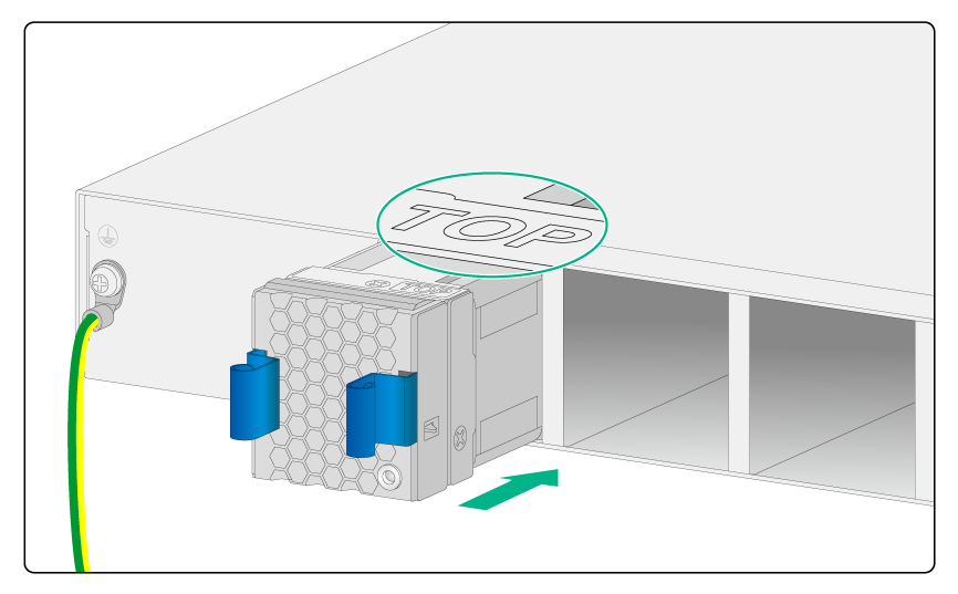
To install a fan tray:
1. Wear an ESD wrist strap and make sure it makes good skin contact and is reliably grounded.
2. Unpack the fan tray and verify that the fan tray model is correct.
3. Orient the fan tray with the "TOP" mark facing upward. Grasp the handle of the fan tray with one hand and support the fan tray bottom with the other, and slide the fan tray along the guide rails into the slot until the fan tray is fully seated in the slot and has a firm contact with the backplane.
Figure2-28 Installing a fan tray (LSPM1FANSA-SN)
Removing a fan tray
|
|
WARNING! · Ensure electricity safety and never touch the rotating fans when you hot-swap a fan tray. · To prevent an unbalanced fan from causing loud noise, do not touch the fans, even if they are not rotating. · Do not touch any bare wires and terminals on a fan tray. · Do not place a fan tray in a moist location or let liquid flow into it. · Contact H3C Support if the circuits or components on a fan tray are faulty. Do not remove any fan tray components. |
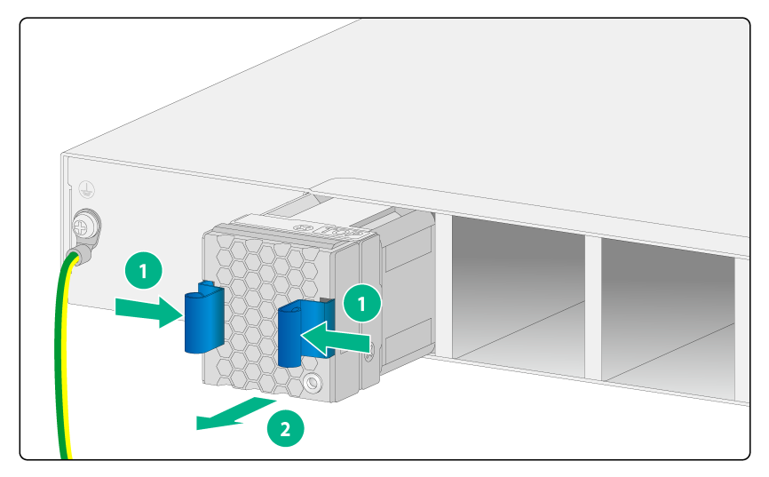
The procedure of removing fan trays is the same for the S6116 switches. This section uses the S6116-48X switch as an example to describe how to remove a fan tray.
1. Wear an ESD wrist strap and make sure it makes good skin contact and is reliably grounded.
2. Press the fan tray handles towards each other to disengage the fan tray from the chassis. Then pull out the fan tray slowly out of the slot along the guide rails.
3. Place the removed fan tray in an antistatic bag.
Figure2-29 Removing a fan tray (LSPM1FANSA-SN)
Installing and removing a power supply
The switch came with power supply slot PWR1 empty and power supply slot PWR2 installed with a filler panel. As a best practice, install two power supplies of the same model for the switch.
Select power supplies for the switch as required. For the power supplies available for the switch and their specifications, see H3C S6116 Ultra-Low Latency Switch Series Hardware Information and Specifications.
Precautions
· Provide a separate circuit breaker for each power supply.
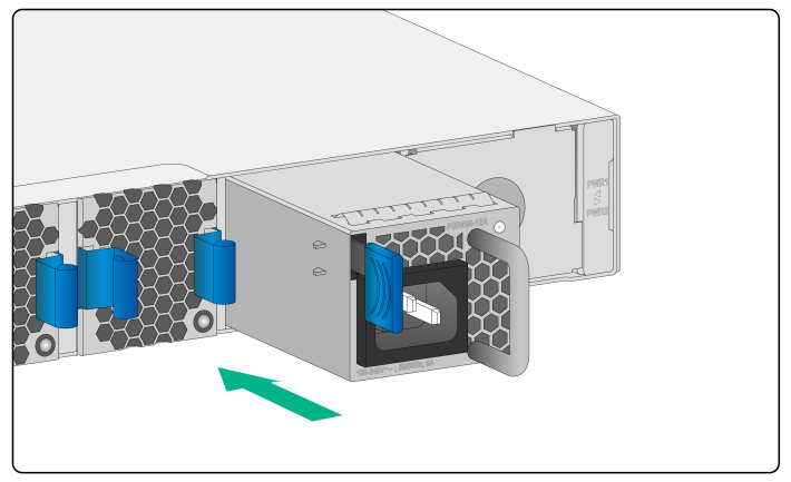
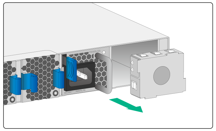
· To avoid device damage and body injury, strictly follow procedures in Figure2-30 and Figure2-31 to install and remove a power supply, respectively.
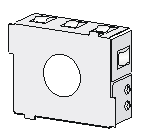
Figure2-30 Installation procedure
![]()
![]()
· If a power supply slot is empty, install a filler panel in it to ensure adequate heat dissipation.
Installing a power supply
To install a power supply:
1. Wear an ESD wrist strap and make sure it makes good skin contact and is reliably grounded.
2. Unpack the power supply and verify that the power supply model is correct.
3. Correctly orient the power supply with the lettering on it upward. Grasp the handle of the power supply with one hand and support its bottom with the other, and slide the power supply slowly along the guide rails into the slot. Make sure the power supply has good contact with the backplane.
To prevent connector damages, insert the power supply gently. The power supply and power supply slot have disorientation rejection designs. If you encounter a hard resistance while inserting the power supply, pull out the power supply and insert it again.
Figure2-32 Installing a power supply
|
|
IMPORTANT: If the target power supply slot has a filler panel installed, first remove the filler panel from the slot (as shown Figure2-33). |
Figure2-33 Removing the filler panel from a power supply slot
Removing a power supply
|
|
CAUTION: When the switch has two power supplies in 1+1 redundancy mode, removing one power supply does not affect the operation of the switch. When the switch has only one power supply installed, removing the power supply powers off the switch. |
Removing a PSR450-12A/PSR450-12A1 power supply
The procedure of removing a PSR450-12A or PSR450-12A1 power supply is the same for the S6116 switches. The following procedure removes a PSR450-12A power supply from an S6116-48X switch.
To remove a PSR450-12A power supply:
1. Wear an ESD wrist strap and make sure it makes good skin contact and is reliably grounded.
2. Remove the power cord.
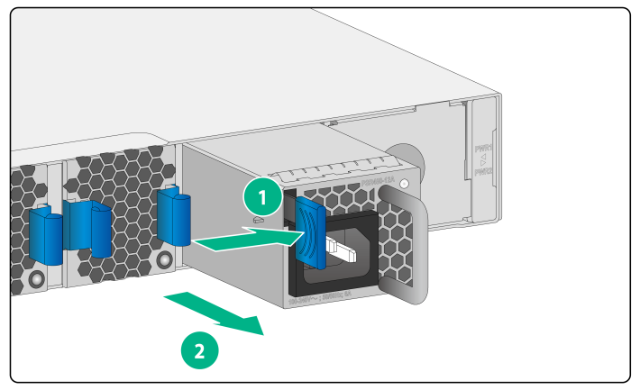
3. Hold the handle on the power supply with one hand, pivot the latch on the power supply to the right with your thumb, and pull the power supply part way out of the slot, as shown in Figure2-34.
4. Supporting the power supply bottom with one hand, slowly pull the power supply out with the other hand.
5. Place the removed power supply in an antistatic bag for future use.
Figure2-34 Removing a PSR450-12A power supply
|
(1) Pivot the latch to the right with your thumb |
(2) Pull the power supply out |
Removing a PSR450-12AHD power supply
The procedure of removing a PSR450-12AHD power supply is the same for the S6116 switches. The following procedure removes a PSR450-12AHD power supply from an S6116-48X switch.
To remove a PSR450-12AHD power supply:
1. Wear an ESD wrist strap and make sure it makes good skin contact and is reliably grounded.
2. Remove the power cord from the power supply.
a. Release the locking tab on the cable clamp and then open the cable clamp (see Figure2-35).
b. Remove the power cord connector from the power supply (see Figure2-36).
Figure2-35 Opening the cable clamp
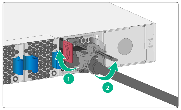
Figure2-36 Removing the power cord from the power supply
3. Hold the handle of the power supply with one hand, press the latch on the power supply to the right with your thumb, and simultaneously pull the power supply part way out of the slot. Supporting the power supply bottom with the other hand, slowly pull the power supply out of the slot along the guide rails.
4. Put the removed power supply in an antistatic bag for future use.
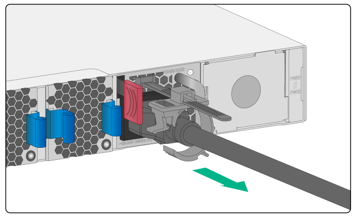
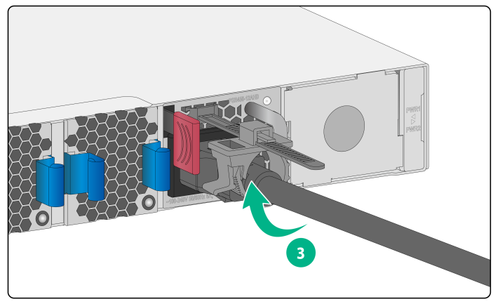
Removing a PSR450-12D DC power supply
The procedure of removing a PSR450-12D power supply is the same for the S6116 switches. The following procedure removes a PSR450-12D power supply from an S6116-48X switch.
To remove a PSR450-12D power supply:
1. Wear an ESD wrist strap and make sure it makes good skin contact and is reliably grounded.
2. Use a flat-head screwdriver to loosen the screws on the power cord connector, and then pull the connector out to remove the power cord. See Figure2-37.
3. Hold the handle on the power supply with one hand, pivot the latch on the power supply to the right with your thumb, and simultaneously pull the power supply part way out of the slot. Supporting the power supply bottom with the other, slowly pull the power supply out of the slot. See Figure2-34.
4. Put the removed power supply in an antistatic bag.
Figure2-37 Removing a PSR450-12D power supply
|
(1) Use a flat-head screwdriver to loosen the screws on the power cord connector |
|
(2) Pull the power cord connector out |
Connecting the power cord
|
|
WARNING! Provide a circuit breaker for each power input. When you connect a power cord, make sure the circuit breaker is switched off. |
Connecting the power cord for a PSR450-12A/PSR450-12A1 power supply
1. Insert the female connector of the power cord supplied with the power supply into the power receptacle on the power supply.
2. Use a releasable cable tie to secure the power cord to the handle of the power supply, as shown in Figure2-38.
3. Connect the other end of the power cord to an AC or DC power source.
Figure2-38 Connecting the power cord (PSR450-12A power supply)
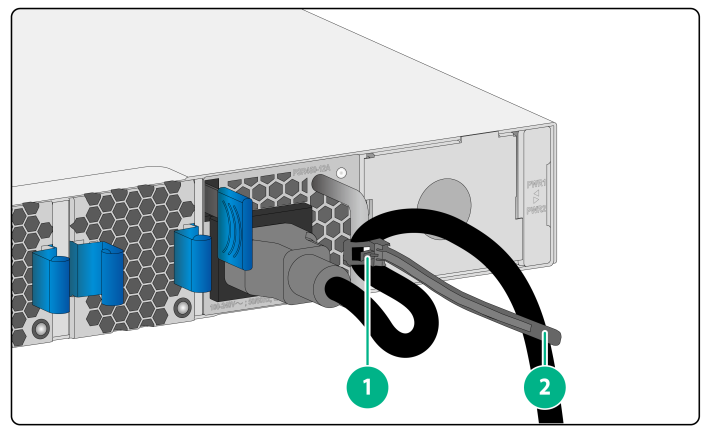
|
(1) Releasable cable tie |
|
(2) Fasten the cable tie to secure the power cord to the handle of the power supply |
Connecting the power cord for a PSR450-12AHD power supply
1. Slide the cable clamp onto the tie mount on the power supply, as shown in Figure2-39.
2. Connect the female connector of the power cord to the power receptacle on the power supply, as shown in Figure2-40
3. Close the cable clamp and slide it forward until it is flush against the edge of the female connector, as shown in Figure2-41.
4. Connect the other end of the power cord to an AC or DC power source.
Figure2-39 Connecting the power cord for a PSR450-12AHD power supply (1)

Figure2-40 Connecting the power cord for a PSR450-12AHD power supply (2)
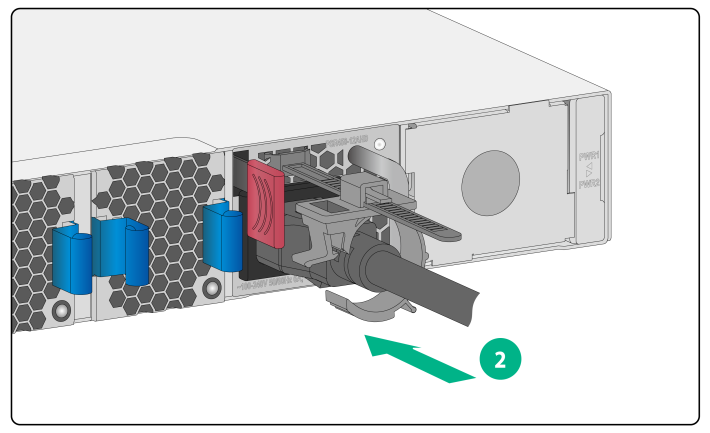
Figure2-41 Connecting the power cord for a PSR450-12AHD power supply (3)
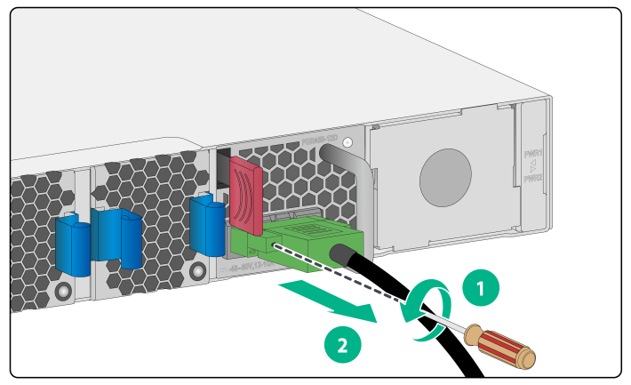
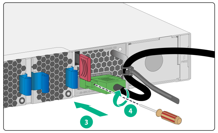
Connecting the DC power cord for a PSR450-12D power supply
1. As shown by callouts 1 and 2 in Figure2-42, use a flat-head screwdriver to remove the two captive screws from the protection cover over the DC power input receptacle.
2. As shown by callout 3 in Figure2-43, correctly orient the DC power cord connector and insert the connector into the power receptacle on the power supply.
If you orient the DC power cord connector upside down, you cannot insert the connector into the power receptacle.
3. As shown by callout 4 in Figure2-43, use a flat-head screwdriver to fasten the screws on the power cord connector.
4. Connect the other end of the power cord to a DC power source.
Figure2-42 Connecting the DC power cord for a PSR450-12D power supply (1)

Figure2-43 Connecting the DC power cord for a PSR450-12D power supply (2)
If the provided DC power cord cannot meet your connection requirements, use the following table to prepare a suitable copper cable as the DC power cord.
Table2-4 Requirements for a suitable DC power cord
|
Power supply model |
Power cord connector |
Minimum cross sectional area of the conductor |
Cross sectional area of the provided power cord |
Maximum cross sectional area of the conductor |
|
PSR450-12D |
Use the connector of the provided power cord |
2.1 mm2 or 14 AWG |
3.3 mm2 or 12 AWG |
3.3 mm2 or 12 AWG |
Verifying the installation
After you complete the installation, verify the following items:
· There is enough space for heat dissipation around the switch, and the rack is stable.
· The grounding cable is securely connected.
· The power source is as required by the switch.
· The power cords are correctly connected.
· All the interface cables are cabled indoors. The switch does not support outdoor cable routing.
3 Accessing the switch for the first time
Connecting the switch to a configuration terminal
You can connect the switch to a configuration terminal from the serial console port.
In Figure3-1, the switch is connected to a configuration terminal (PC as an example) from the serial console port.
Figure3-1 Connecting the switch to a configuration terminal from the serial console port
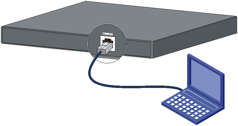
As shown in Table3-1, you can only use a DB9-to-RJ45 console cable to connect the switch to a configuration terminal. The switch is not provided with a DB9-to-RJ45 console cable. Prepare one yourself.
Table3-1 Configuration terminal connection methods and console cables
|
Connection method |
Console cable type |
Configuration terminal-side connector |
Switch-side connector |
|
Using the serial console port for connection |
DB9-to-RJ45 console cable |
DB-9 female connector |
RJ-45 connector |
The signal pinout for the RJ-45 connector of a serial console cable varies by vendor. To avoid abnormal configuration terminal display, use a serial console cable provided by H3C as shown in Table3-2. To prepare a serial console cable yourself, make sure the signal pinout for the RJ-45 connector is the same as that shown in Table3-3.
|
Console cable type |
Console cable view |
Product code of the recommended H3C console cable |
|
DB9-to-RJ45 console cable |
|
04042967 |

Connecting a DB9-to-RJ45 console cable
|
|
CAUTION: Follow these guidelines when you connect a DB9-to-RJ45 console cable: · Identify the mark on the serial console port and make sure you are connecting to the correct port. · The serial ports on PCs do not support hot swapping. To connect a PC to an operating switch, first connect the PC end. To disconnect a PC from an operating switch, first disconnect the switch end. |
A DB9-to-RJ45 console cable is an 8-core shielded cable, with a crimped RJ-45 connector at one end for connecting to the serial console port of the switch, and a DB-9 female connector at the other end for connecting to the serial port on the console terminal.
Figure3-2 DB9-to-RJ45 console cable
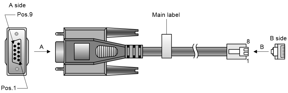
Table3-3 DB9-to-RJ45 console cable signal pinout
|
RJ-45 |
Signal |
DB-9 |
Signal |
|
1 |
RTS |
8 |
CTS |
|
2 |
DTR |
6 |
DSR |
|
3 |
TXD |
2 |
RXD |
|
4 |
SG |
5 |
SG |
|
5 |
SG |
5 |
SG |
|
6 |
RXD |
3 |
TXD |
|
7 |
DSR |
4 |
DTR |
|
8 |
CTS |
7 |
RTS |
To connect the switch to a configuration terminal (for example, a PC) through a DB9-to-RJ45 console cable:
1. Plug the DB-9 female connector of the DB9-to-RJ45 console cable to the serial port on the PC.
2. Connect the RJ-45 connector to the serial console port on the switch.
Setting terminal parameters
To configure and manage the switch from the serial console port, you must run a terminal emulator program, TeraTermPro or PuTTY, on your configuration terminal. You can use the emulator program to connect a network device, a Telnet site, or an SSH site. For more information about the terminal emulator programs, see the user guides for these programs
Configure the terminal parameters as follows:
· Bits per second—9600.
· Data bits—8.
· Stop bits—1.
· Parity—None.
· Flow control—None.
Starting the switch
1. Before powering on the switch, verify that the following requirements are met:
¡ The power cords are correctly connected.
¡ The input power voltage meets the requirement of the switch.
¡ The console cable is correctly connected.
¡ The configuration terminal (a PC, for example) has started, and the parameters are set correctly.
2. Power on the switch.
During the startup process, you can access Boot ROM menus to perform tasks such as software upgrade and file management. The Boot ROM interface and menu options vary by software versions. For more information about Boot ROM menu options, see the software-matching release notes for the device.
3. After the startup completes, you can access the CLI to configure the switch.
For more information about the configuration commands and CLI, see H3C S6116 Ultra-Low Latency Switch Series Configuration Guides and H3C S6116 Ultra-Low Latency Switch Series Command References.
4 Maintenance and troubleshooting
Power supply failure
You can determine whether a power supply is faulty by observing the status LED on the power supply. For more information about the status LED on a power supply, see H3C PSR450 Power Module Series User Manual.
Symptom
The status LED on a power supply is not steady green.
Solution
To resolve the issue:
1. Verify that the power cord is correctly connected.
2. Verify that the power source is as required by the power supply.
3. Verify that the operating temperature of the switch is in an acceptable range and good ventilation is provided for the power supply.
4. If the issue persists, contact H3C Support
To replace a power supply, see "Installing and removing a power supply."
Fan tray failure
|
|
CAUTION: If more than one fan tray fails while the switch is operating, do not remove the failed fan trays simultaneously. Replace the fan trays one by one and finish replacing each fan tray within 3 minutes. |
Symptom
The status LED on a fan tray is steady on and the system outputs a message that indicates a fan tray failure.
Solution
Replace the failed fan tray. For more information, see "Installing and removing a fan tray."
Configuration terminal display issues
No display on the configuration terminal
Symptom
The configuration terminal does not have display when the switch is powered on.
Solution
To resolve the issue:
1. Verify that the power system is operating correctly.
2. Verify that the console cable has been connected correctly and the console cable is in good condition.
3. Verify that terminal parameter settings are correct:
¡ Baud rate—9600.
¡ Data bits—8.
¡ Stop bits—1.
¡ Parity—None.
¡ Flow control—None.
4. If the issue persists, contact H3C Support.
Garbled display on the configuration terminal
Symptom
The configuration terminal displays garbled text when the switch is powered on.
Solution
To resolve the issue:
1. Verify that the terminal parameter settings are correct:
¡ Baud rate—9600.
¡ Data bits—8.
¡ Stop bits—1.
¡ Parity—None.
¡ Flow control—None.
2. If the issue persists, contact H3C Support.
