- Table of Contents
- Related Documents
-
| Title | Size | Download |
|---|---|---|
| 01-Text | 530.00 KB |
Overview
About the power module
The PSR1600B-12A-B is an AC-input and DC-output power module. It provides a maximum output of 1600 W.
The power module has the following features:
· Self-protection—The power module provides a self-protection mechanism against input overcurrent, input undervoltage, output overcurrent, output overvoltage, output short circuit, and overtemperature conditions.
· Redundancy—The power module can work together with a second one or more to achieve N+1 or N+N redundancy and load sharing.
· Hot swapping—The power module can be installed on or removed from an operating device. You can remove a power module only when the remaining power modules can provide sufficient power for the device.
Technical specifications
|
Item |
Specification |
|
Rated AC input voltage |
100 VAC to 240 VAC @ 50 Hz or 60 Hz |
|
Max AC input voltage |
90 VAC to 290 VAC @ 47 Hz to 63 Hz |
|
Rated HVDC input voltage |
240V DC |
|
Max HVDC input voltage |
180V~320V DC |
|
Output voltage |
12 V |
|
Maximum output current |
131 A (12 V) |
|
Maximum output power |
1600 W |
|
Dimensions (H × W × D) (including the handle) |
40.2 × 73.5 × 253.8 mm (1.58 × 2.89 × 9.99 in) |
|
Ambient temperature, operating |
–10°C to +55°C (+14°F to +131°F) |
|
Ambient humidity (RH), noncondensing |
5% to 95% |
|
|
CAUTION: Whether the power module supports high-voltage DC input depends on the device model. For information, see hardware information and specifications for the device. |
Views
Figure 1 PSR1600B-12A-B power module view
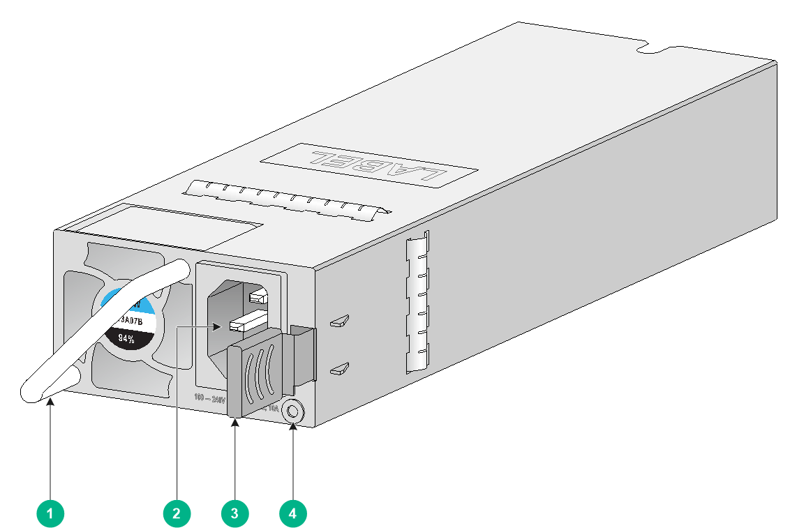
|
(1) Handle |
(2) AC-input receptacle |
|
(3) Latch |
(4) Status LED |
LEDs
The power module has a LED to indicate its operating status.
|
LED status |
Description |
|
Steady green |
The power module is operating correctly, and is in active state. |
|
Flashing green at 1 Hz |
The power module is operating correctly, and is in standby state. |
|
Flashing green at 2 Hz |
The power module is updating the software. |
|
Steady amber |
The power module is faulty or in self-protection mode. |
|
Flashing amber at 1 Hz |
Abnormal power output. (Output overvoltage, output undervoltage, output overcurrent, output overpower, or overtemperature has occurred. The power module has not entered self-protection mode.) |
|
Flashing amber at 2 Hz |
The power module does not have power input but other power modules in the device have power input. |
|
Off |
No power modules in the device have power input. |
Installing and removing the power module
Safety precautions
To avoid injuring yourself or damaging the power module and device, follow these safety precautions:
· When installing and removing the power module, wear an ESD wrist strap. Make sure the strap makes good skin contact and is reliably grounded.
· To avoid damaging the power module and device, make sure the external power source provides a voltage as required by the power module and the power module output voltage is as required by the device.
· To avoid bodily injury, do not touch any bare cables or terminals of the power module.
· Do not place the power module in a wet area, and prevent liquid from flowing into the power module.
· To avoid power module damage, do not open the power module. When an internal circuit or component is faulty, contact H3C Support.
Installation tools
You must wear an ESD wrist strap when installing or removing the power module. Prepare one yourself.
Installing the power module
To avoid bodily injury or device damage, strictly follow the procedure in Figure 2 to install the power module.
Figure 2 Power module installation procedure
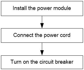
To install the power module:
1. Wear an ESD wrist strap, and make sure the strap makes good skin contact and is reliably grounded.
2. Unpack the power module. Make sure the power module model is as required.
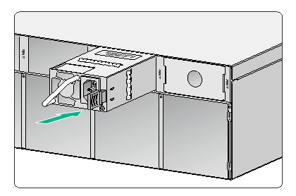
3. As shown in Figure 3, correctly orient the power module. Holding the power module handle with one hand and supporting the power module bottom with the other, align the power module with the target power module slot. Push the power module slowly into the slot along the guide rails until the latch clicks and locks in place.
Make sure the power module makes good contact with the backplane connector of the device.
If you encounter a hard resistance while inserting the power module, pull out the power module, orient it correctly, and then insert it again.
Figure 3 Installing the power module
|
|
IMPORTANT: Keep safe the filler panel for the power module slot and the package for the power module. |
Connecting the power cord
|
|
WARNING! · Make sure each power cord has a separate circuit breaker. · Before connecting the power cord, make sure the circuit breaker for it is turned off. |
To connect the power cord:
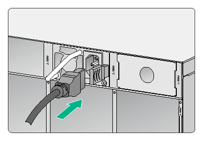
1. As shown in Figure 4, connect the female connector of the AC power cord into the AC-input receptacle on the power module.
Figure 4 Connecting the AC power cord
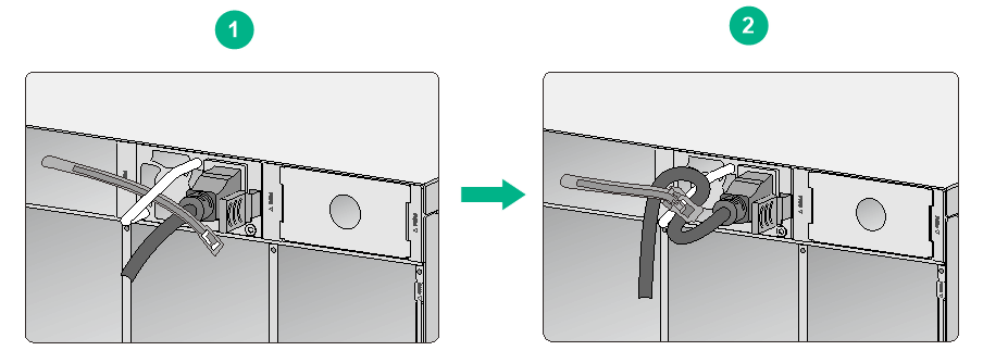
2. As shown in Figure 5, use a cable tie to secure the power cord to the handle of the power module.
Figure 5 Securing the AC power cord
3. Connect the other end of the power cord to an external AC power source and turn on the circuit breaker.
4. Examine the status LED on the power module to verify that the power module is operating correctly.
If the LED is steady green or flashing green, the power cord is connected correctly. If the LED is off or amber, check the installation and fix the issues.
Removing the power module
To avoid bodily injury or device damage, strictly follow the procedure in Figure 6 to remove the power module.
Figure 6 Power module removal procedure
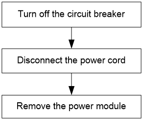
To remove the power module:
1. Turn off the circuit breaker.
2. Wear an ESD wrist strap, and make sure the strap makes good skin contact and is reliably grounded.
3. Loosen and remove the cable tie, and then remove the power cord.
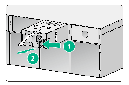
4. As shown in Figure 7, use one hand to hold the power module handle, press the latch towards the handle, and then pull the power module part way out of the slot. Supporting the power module with the other hand, pull it completely out of the slot.
Figure 7 Removing the power module
5. Place the removed power module on an anti-static mat or put it into its original package.
6. If you are not to install a new power module, install a filler panel in the slot to prevent dust and ensure good ventilation in the device.
