- Table of Contents
-
- 09-Security Configuration Guide
- 00-Preface
- 01-AAA configuration
- 02-802.1X configuration
- 03-MAC authentication configuration
- 04-Portal configuration
- 05-Web authentication configuration
- 06-Port security configuration
- 07-User profile configuration
- 08-Password control configuration
- 09-Keychain configuration
- 10-Public key management
- 11-PKI configuration
- 12-SSH configuration
- 13-SSL configuration
- 14-Object group configuration
- 15-Attack detection and prevention configuration
- 16-TCP attack prevention configuration
- 17-IP source guard configuration
- 18-ARP attack protection configuration
- 19-ND attack defense configuration
- 20-uRPF configuration
- 21-SAVI configuration
- 22-SAVA configuration
- 23-MFF configuration
- 24-Crypto engine configuration
- 25-FIPS configuration
- 26-MACsec configuration
- 27-Microsegmentation configuration
- Related Documents
-
| Title | Size | Download |
|---|---|---|
| 19-ND attack defense configuration | 159.29 KB |
Contents
ND attack defense tasks at a glance
Configuring ND packet rate limit
Enabling source MAC consistency check for ND messages
Configuring ND attack detection
Restrictions and guidelines for ND attack detection configuration
Configuring ND attack detection for a VLAN
Ignoring ingress ports of ND packets
Enabling ND attack detection logging
Display and maintenance commands for ND attack detection
Example: Configuring ND attack detection
Specifying the role of the attached device
Configuring and applying an RA guard policy
Enabling the RA guard logging feature
Display and maintenance commands for RA guard
Configuring IPv6 destination guard
Restrictions and guidelines: IPv6 destination guard configuration
Enabling/disabling IPv6 destination guard globally
Enabling/disabling IPv6 destination guard on an interface
Display and maintenance commands for IPv6 destination guard
Configuring ND keepalive entry scanning
About ND keepalive entry scanning
Configuring ND keepalive entry scanning
Display and maintenance commands for ND keepalive entry scanning
Enabling SNMP notifications for ND
Configuring ND attack defense
About ND attack defense
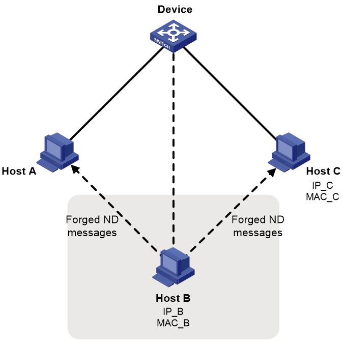
IPv6 Neighbor Discovery (ND) attack defense is able to identify forged ND messages to prevent ND attacks.
The IPv6 ND protocol does not provide any security mechanisms and is vulnerable to network attacks. As shown in Figure 1, an attacker can send the following forged ICMPv6 messages to perform ND attacks:
· Forged NS/NA/RS messages with an IPv6 address of a victim host. The gateway and other hosts update the ND entry for the victim with incorrect address information. As a result, all packets intended for the victim are sent to the attacking terminal.
· Forged RA messages with the IPv6 address of a victim gateway. As a result, all hosts attached to the victim gateway maintain incorrect IPv6 configuration parameters and ND entries.
ND attack defense tasks at a glance
All ND attack defense tasks are optional.
· Configuring ND packet rate limit
· Enabling source MAC consistency check for ND messages
· Configuring ND attack detection
· Configuring IPv6 destination guard
· Configuring ND keepalive entry scanning
· Enabling SNMP notifications for ND
Configuring ND packet rate limit
About this task
This feature limits the receiving rate of ND packets that are to be delivered to the CPU, preventing the CPU from being overwhelmed by ND packets.
Enabled with ND attack detection, the device redirects the received ND packets to the CPU for security check. If attackers send a large number of forged ND packets to the device, the CPU will be overloaded. As a result, other features might malfunction and the device might crash. To avoid this situation, configure ND packet rate limit on ND packet receiving interfaces. When the receiving rate of ND packets on the interfaces exceeds the rate limit, the packets that exceed the limit will be discarded.
When logging for ND packet rate limit is enabled, the device sends the highest threshold-crossed ND packet rate within the sending interval in a log message to the information center. You can configure the information center module to set the log output rules. For more information about information center, see Network Management and Monitoring Configuration Guide.
Restrictions and guidelines
As a best practice, configure this feature if the device is configured with ND attack detection or ND snooping or has detected ND flood attacks.
To prevent the device from sending log messages frequently, set the log message sending interval to a high value.
On a Layer 2 aggregate interface, if you enable ND packet rate limit and the logging for this feature, the device sends log messages upon limit violations on its member ports.
Procedure
1. Enter system view.
system-view
2. (Optional.) Enable logging for ND packet rate limit.
ipv6 nd rate-limit log enable
By default, logging for ND packet rate limit is disabled.
3. (Optional.) Set the log message sending interval.
ipv6 nd rate-limit log interval interval
By default, the device sends log messages every 60 seconds.
4. Enter interface view.
interface interface-type interface-number
Supported interfaces include Layer 2 Ethernet interfaces, Layer 2 aggregate interfaces, Layer 3 Ethernet interfaces, and Layer 3 aggregate interfaces.
5. Enable ND packet rate limit.
ipv6 nd rate-limit [ pps ]
By default, ND packet rate limit is enabled.
Enabling source MAC consistency check for ND messages
About this task
The source MAC consistency check feature is typically configured on gateways to prevent ND attacks.
This feature checks the source MAC address and the source link-layer address for consistency for each arriving ND message.
· If the source MAC address and the source link-layer address are not the same, the device drops the packet.
· If the addresses are the same, the device continues learning ND entries.
The ND logging feature logs source MAC inconsistency events, and it sends the log messages to the information center. The information center can then output log messages from different source modules to different destinations. For more information about the information center, see Network Management and Monitoring Configuration Guide.
Procedure
1. Enter system view.
system-view
2. Enable source MAC consistency check for ND messages.
ipv6 nd mac-check enable
By default, source MAC consistency check is disabled for ND messages.
3. (Optional.) Enable the ND logging feature.
ipv6 nd check log enable
By default, the ND logging feature is disabled.
As a best practice, disable the ND logging feature to avoid excessive ND logs.
Configuring ND attack detection
About ND attack detection
ND attack detection checks incoming ND messages for user validity to prevent spoofing attacks. It is typically configured on access devices.
ND attack detection is applicable to VLANs.
ND attack detection defines the following types of interfaces on a VLAN network:
· ND trusted interface—Performs no user validity check on the received ND messages.
· ND untrusted interface—Discards incoming RA and redirect messages, and performs the user validity check on other types of incoming ND messages.
ND attack detection compares the source IPv6 address and the source MAC address in an incoming ND message against security entries from other modules.
· If a match is found, the device verifies the user as legal, and it forwards the packet.
· If no match is found, the device verifies the user as illegal, and it discards the ND message.
ND attack detection uses static IPv6 source guard binding entries, ND snooping entries, and DHCPv6 snooping entries for user validity check.
· Static IPv6 source guard binding entries are created by using the ipv6 source binding command. For information about IPv6 source guard, see "Configuring IP source guard."
· DHCPv6 snooping entries are automatically generated by the DHCPv6 snooping feature. For information about DHCPv6 snooping, see Layer 3–IP Services Configuration Guide.
Restrictions and guidelines for ND attack detection configuration
When you configure ND attack detection, follow these restrictions and guidelines:
· To prevent ND untrusted interfaces from dropping all received ND messages, make sure IPv6 source guard static bindings, DHCPv6 snooping, or both features are configured.
· To make the IPv6 source guard static bindings effective for ND attack detection, you must perform the following operations:
¡ Specify the vlan vlan-id option in the ipv6 source binding command.
¡ Enable ND attack detection for the same VLAN.
Configuring ND attack detection for a VLAN
1. Enter system view.
system-view
2. Enter VLAN view.
vlan vlan-id
3. Enable ND attack detection.
ipv6 nd detection enable
By default, ND attack detection is disabled.
4. (Optional.) Configure the interface as ND trusted interface:
a. Return to system view.
quit
b. Enter Layer 2 Ethernet or aggregate interface view.
interface interface-type interface-number
c. Configure the interface as ND trusted interface.
ipv6 nd detection trust
By default, all interfaces are ND untrusted interfaces.
Ignoring ingress ports of ND packets
About this task
With ND attack detection enabled, the device can perform security check on received packets based on the local and remote IPSG bindings. Remote IPSG bindings do not contain port information. The device drops ND packets that match remote IPSG bindings because it does not find matching ingress ports for these packets. To prevent the device from dropping these packets, you can configure the device to ignore ingress ports of ND packets. This feature does not examine the ingress ports of ND packets, so that ND packets that match remote IPSG bindings will not be dropped.
Procedure
1. Enter system view.
system-view
2. Ignore ingress ports of ND packets in ND attack detection.
ipv6 nd detection port-match-ignore
By default, ingress ports of ND packets are examined in ND attack detection.
Enabling ND attack detection logging
About this task
This feature allows a device to generate logs when it detects invalid ND packets. The log information helps administrators locate and solve problems. Each log records the following information:
· Victim port numbers in a VLAN.
· Source IP address of the invalid ND packets.
· Source MAC address of the invalid ND packets.
· VLAN ID of the invalid ND packets.
· Total number of dropped ND packets.
Procedure
1. Enter system view.
system-view
2. Enable ND attack detection logging.
ipv6 nd detection log enable
By default, ND attack detection logging is disabled.
Display and maintenance commands for ND attack detection
Execute display commands in any view and reset commands in user view.
|
Task |
Command |
|
Display statistics for ND messages dropped by ND attack detection. |
display ipv6 nd detection statistics [ interface interface-type interface-number ] |
|
Clear ND attack detection statistics. |
reset ipv6 nd detection statistics [ interface interface-type interface-number ] |
Example: Configuring ND attack detection
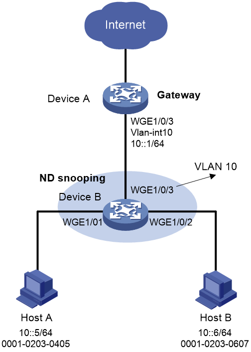
Network configuration
As shown in Figure 2, configure ND attack detection on Device B to check user validity for ND messages from Host A and Host B.
Procedure
# Create VLAN 10.
<DeviceA> system-view
[DeviceA] vlan 10
[DeviceA-vlan10] quit
# Configure Twenty-FiveGigE 1/0/3 to trunk VLAN 10.
[DeviceA] interface twenty-fivegige 1/0/3
[DeviceA-Twenty-FiveGigE1/0/3] port link-type trunk
[DeviceA-Twenty-FiveGigE1/0/3] port trunk permit vlan 10
[DeviceA-Twenty-FiveGigE1/0/3] quit
# Assign IPv6 address 10::1/64 to VLAN-interface 10.
[DeviceA] interface vlan-interface 10
[DeviceA-Vlan-interface10] ipv6 address 10::1/64
[DeviceA-Vlan-interface10] quit
2. Configure Device B:
# Create VLAN 10.
<DeviceB> system-view
[DeviceB] vlan 10
[DeviceB-vlan10] quit
# Configure Twenty-FiveGigE 1/0/1, Twenty-FiveGigE 1/0/2, and Twenty-FiveGigE 1/0/3 to trunk VLAN 10.
[DeviceB] interface twenty-fivegige 1/0/1
[DeviceB-Twenty-FiveGigE1/0/1] port link-type access
[DeviceB-Twenty-FiveGigE1/0/1] port access vlan 10
[DeviceB-Twenty-FiveGigE1/0/1] quit
[DeviceB] interface twenty-fivegige 1/0/2
[DeviceB-Twenty-FiveGigE1/0/2] port link-type access
[DeviceB-Twenty-FiveGigE1/0/2] port access vlan 10
[DeviceB-Twenty-FiveGigE1/0/2] quit
[DeviceB] interface twenty-fivegige 1/0/3
[DeviceB-Twenty-FiveGigE1/0/3] port link-type trunk
[DeviceB-Twenty-FiveGigE1/0/3] port trunk permit vlan 10
[DeviceB-Twenty-FiveGigE1/0/3] quit
# Enable ND attack detection for VLAN 10.
[DeviceB] vlan 10
[DeviceB-vlan10] ipv6 nd detection enable
# Enable ND snooping for IPv6 global unicast addresses and ND snooping for IPv6 link-local addresses in VLAN 10.
[DeviceB-vlan10] ipv6 nd snooping enable global
[DeviceB-vlan10] ipv6 nd snooping enable link-local
[DeviceB-vlan10] quit
# Configure Twenty-FiveGigE 1/0/3 as ND trusted interface.
[DeviceB] interface twenty-fivegige 1/0/3
[DeviceB-Twenty-FiveGigE1/0/3] ipv6 nd detection trust
Verifying the configuration
Verify that Device B inspects all ND messages received by Twenty-FiveGigE 1/0/1 and Twenty-FiveGigE 1/0/2 based on the ND snooping entries. (Details not shown.)
Configuring RA guard
About RA guard
RA guard allows Layer 2 access devices to analyze and block unwanted and forged RA messages.
Upon receiving an RA message, the device makes the forwarding or dropping decision based on the role of the attached device or the RA guard policy.
1. If the role of the device attached to the receiving interface is router, the device forwards the RA message. If the role is host, the device drops the RA message.
2. If no attached device role is set, the device uses the RA guard policy applied to the VLAN of the receiving interface to match the RA message.
¡ If the policy does not contain match criteria, the policy will not take effect and the device forwards the RA message.
¡ If the RA message content matches every criterion in the policy, the device forwards the message. Otherwise, the device drops the message.
Specifying the role of the attached device
Restrictions and guidelines
Make sure your setting is consistent with the type of the attached device. If you are not aware of the device type, do not specify a role for the device.
Procedure
1. Enter system view.
system-view
2. Enter interface view.
¡ Enter Layer 2 Ethernet interface view.
interface interface-type interface-number
¡ Enter aggregate interface view.
interface bridge-aggregation interface-number
3. Specify the role of the device attached to the interface.
ipv6 nd raguard role { host | router }
By default, the role of the device attached to the interface is not specified.
Configuring and applying an RA guard policy
About this task
Configure an RA guard policy if you do not specify a role for the attached device or if you want to filter the RA messages sent by a router.
Procedure
1. Enter system view.
system-view
2. Create an RA guard policy and enter its view.
ipv6 nd raguard policy policy-name
3. Configure the RA guard policy.
Choose the following tasks as needed:
¡ Specify an ACL match criterion.
if-match acl { ipv6-acl-number | name ipv6-acl-name }
¡ Specify a prefix match criterion.
if-match prefix acl { ipv6-acl-number | name ipv6-acl-name }
¡ Specify a router preference match criterion.
if-match router-preference maximum { high | low | medium }
¡ Specify an M flag match criterion.
if-match autoconfig managed-address-flag { off | on }
¡ Specify an O flag match criterion.
if-match autoconfig other-flag { off | on }
¡ Specify a maximum or minimum hop limit match criterion.
if-match hop-limit { maximum | minimum } limit
By default, the RA guard policy is not configured.
4. Quit RA guard policy view.
quit
5. Enter VLAN view.
vlan vlan-number
6. Apply an RA guard policy to the VLAN.
ipv6 nd raguard apply policy [ policy-name ]
By default, no RA guard policy is applied to the VLAN.
Enabling the RA guard logging feature
About this task
This feature allows a device to generate logs when it detects forged RA messages. The log information helps administrators locate and solve problems. Each log records the following information:
· Name of the interface that received the forged RA message.
· Source IP address of the forged RA message.
· Number of RA messages dropped on the interface.
The RA guard logging feature sends the log messages to the information center. The information center can then output log messages from different source modules to different destinations. For more information about the information center, see Network Management and Monitoring Configuration Guide.
Procedure
1. Enter system view.
system-view
2. Enable the RA guard logging feature.
ipv6 nd raguard log enable
By default, the RA guard logging feature is disabled.
Display and maintenance commands for RA guard
Execute display commands in any view.
|
Task |
Command |
|
Display the RA guard policy configuration. |
display ipv6 nd raguard policy [ policy-name ] |
|
Display RA guard statistics. |
display ipv6 nd raguard statistics [ interface interface-type interface-number ] |
|
Clear RA guard statistics. |
reset ipv6 nd raguard statistics [ interface interface-type interface-number ] |
Example: Configuring RA guard
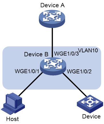
Network configuration
As shown in Figure 3, Twenty-FiveGigE 1/0/1, Twenty-FiveGigE 1/0/2, and Twenty-FiveGigE 1/0/3 of Device B are in VLAN 10.
Configure RA guard on Device B to filter forged and unwanted RA messages.
· Configure an RA policy in VLAN 10 for Twenty-FiveGigE 1/0/2 to filter all RA messages received from the unknown device.
· Specify host as the role of the host. All RA messages received on Twenty-FiveGigE 1/0/1 are dropped.
· Specify router as the role of the Device A. All RA messages received on Twenty-FiveGigE 1/0/3 are forwarded.
Procedure
# Create an RA guard policy named policy1.
<DeviceB> system-view
[DeviceB] ipv6 nd raguard policy policy1
# Set the maximum router preference to high for the RA guard policy.
[DeviceB-raguard-policy-policy1] if-match router-preference maximum high
# Specify on as the M flag match criterion for the RA guard policy.
[DeviceB-raguard-policy-policy1] if-match autoconfig managed-address-flag on
# Specify on as the O flag match criterion for the RA guard policy.
[DeviceB-raguard-policy-policy1] if-match autoconfig other-flag on
# Set the maximum advertised hop limit to 120 for the RA guard policy.
[DeviceB-raguard-policy-policy1] if-match hop-limit maximum 120
# Set the minimum advertised hop limit to 100 for the RA guard policy.
[DeviceB-raguard-policy-policy1] if-match hop-limit minimum 100
[DeviceB-raguard-policy-policy1] quit
# Assign Twenty-FiveGigE 1/0/1 and Twenty-FiveGigE 1/0/2 to VLAN 10.
[DeviceB] interface twenty-fivegige 1/0/1
[DeviceB-Twenty-FiveGigE1/0/1] port link-type access
[DeviceB-Twenty-FiveGigE1/0/1] port access vlan 10
[DeviceB-Twenty-FiveGigE1/0/1] quit
[DeviceB] interface twenty-fivegige 1/0/2
[DeviceB-Twenty-FiveGigE1/0/2] port link-type access
[DeviceB-Twenty-FiveGigE1/0/2] port access vlan 10
[DeviceB-Twenty-FiveGigE1/0/2] quit
# Configure Twenty-FiveGigE 1/0/3 to trunk VLAN 10.
[DeviceB] interface twenty-fivegige 1/0/3
[DeviceB-Twenty-FiveGigE1/0/3] port link-type trunk
[DeviceB-Twenty-FiveGigE1/0/3] port trunk permit vlan 10
[DeviceB-Twenty-FiveGigE1/0/3] quit
# Apply the RA guard policy policy1 to VLAN 10.
[DeviceB] vlan 10
[DeviceB-vlan10] ipv6 nd raguard apply policy policy1
[DeviceB-vlan10] quit
# Specify host as the role of the device attached to Twenty-FiveGigE 1/0/1.
[DeviceB] interface twenty-fivegige 1/0/1
[DeviceB-Twenty-FiveGigE1/0/1] ipv6 nd raguard role host
[DeviceB-Twenty-FiveGigE1/0/1] quit
# Specify router as the role of the device attached to Twenty-FiveGigE 1/0/3.
[DeviceB] interface twenty-fivegige 1/0/3
[DeviceB-Twenty-FiveGigE1/0/3] ipv6 nd raguard role router
[DeviceB-Twenty-FiveGigE1/0/3] quit
Verifying the configuration
# Verify that the device forwards or drops RA messages received on Twenty-FiveGigE 1/0/2 based on the RA guard policy. (Details not shown.)
# Verify that the device drops RA messages received on Twenty-FiveGigE 1/0/1. (Details not shown.)
# Verify that the device forwards RA messages received on Twenty-FiveGigE 1/0/3 to other interfaces in VLAN 10. (Details not shown.)
Configuring IPv6 destination guard
About IPv6 destination guard
IPv6 destination guard ensures that the device resolves IPv6 destination IP addresses only when the IP addresses have matching DHCPv6 relay entries or IP source guard bindings. The feature ensures that users can access only valid and active terminals, and reduces the number of ND entries on the device, improving device performance.
Before sending out a packet to an IPv6 address, the device performs the IPv6 destination guard as follows:
1. Searches DHCPv6 relay entries for a match based on the destination IPv6 address and packet output interface.
¡ If a match is found, the device initiates ND resolution from the output interface. If the resolution succeeds, the device sends out the packet. If the resolution fails, the device drops the packet.
¡ If no match is found, the device proceeds to the next step.
2. Searches IP source guard binding table for a match based on the destination IPv6 address and packet output interface.
¡ If a match is found, the device initiates ND resolution from the output interface. If the resolution succeeds, the device sends out the packet. If the resolution fails, the device drops the packet.
¡ If no match is found, the device does not initiate ND resolution and drops the packet.
The device enters stressed mode when the CPU or memory usage exceeds their thresholds or the number of unresolved ND entries exceeds a specific value. If the device continues resolving a large number of IPv6 addresses in stressed mode, the CPU will be overloaded and the device will crash. To reduce the workload of the device, specify the stressed keyword. In this case, IPv6 destination guard is enabled after device enters stressed mode. The device resolves only IPv6 addresses that pass the IPv6 destination guard check.
For more information about DHCPv6 relay entries, see DHCPv6 relay agent configuration in Layer 3—IP Services Configuration Guide. For more information about IP source guard entries, see "Configuring IP source guard."
Restrictions and guidelines: IPv6 destination guard configuration
You can enable IPv6 destination guard globally or on an interface.
For an interface, the interface-specific IPv6 destination guard status configuration has higher priority than the global IPv6 destination guard status.
If IPv6 destination guard is not enabled on an interface, the IPv6 destination guard status on the interface is determined by the global IPv6 destination guard status.
Enabling/disabling IPv6 destination guard globally
1. Enter system view.
system-view
2. Enable or disable IPv6 destination guard globally.
¡ Enable IPv6 destination guard globally.
ipv6 destination-guard global enable [ stressed ]
¡ Disable IPv6 destination guard globally.
undo ipv6 destination-guard global enable
By default, IPv6 destination guard is disabled globally.
Enabling/disabling IPv6 destination guard on an interface
1. Enter system view.
system-view
2. Enter system view.
interface interface-type interface-number
3. Enable or disable IPv6 destination guard on an interface.
¡ Enable IPv6 destination guard on an interface.
ipv6 destination-guard enable [ stressed ]
¡ Disable IPv6 destination guard on an interface.
ipv6 destination-guard disable
By default, the interface-specific IPv6 destination guard status is consistent with the global IPv6 destination guard status.
Display and maintenance commands for IPv6 destination guard
Execute display commands in any view.
|
Task |
Command |
|
Display IPv6 destination guard status. |
display ipv6 destination-guard [ interface interface-type interface-number ] |
Configuring ND keepalive entry scanning
About ND keepalive entry scanning
In a large-scale network, it takes a long time for ND scanning to identify the hosts that go offline abnormally if you specify a large scanning range. After you enable ND keepalive entry scanning, the system can quickly locate those hosts and monitor the host status within the aging time.
When users come online, the system generates dynamic ND entries and IPSG binding entries. Enabled with ND keepalive entry scanning, the system also creates online keepalive entries when users come online. If users go offline, the corresponding ND entries are deleted and the status of the keepalive entries is set to offline. The device sends NS packets at intervals to the IPv6 addresses in the offline keepalive entries until the keepalive entries become online again or are deleted when the aging time expires. The interval varies with the number of NS packets that have been sent to the IPv6 address in an offline keepalive entry. For more information about IP source guard configuration, see Security Configuration Guide.
Configuring ND keepalive entry scanning
1. Enter system view.
system-view
2. (Optional.) Set the NS packet sending rate for keepalive entry scanning.
ipv6 nd scan keepalive send-rate pps
By default, the device sends NS packets at a rate of 48 pps during keepalive entry scanning.
3. (Optional.) Set the aging time for ND keepalive entries.
ipv6 nd scan keepalive aging-time time
By default, the aging time for ND keepalive entries is 60 minutes.
4. Enter interface view.
interface interface-type interface-number
5. Enable the ND keepalive entry scanning feature.
ipv6 nd scan keepalive enable
By default, the ND keepalive entry scanning is disabled on an interface.
Display and maintenance commands for ND keepalive entry scanning
Execute display commands in any view and reset commands in user view.
|
Task |
Command |
|
Display ND keepalive entries. |
display ipv6 nd scan keepalive entry [ interface interface-type interface-number ] [ count ] |
|
Display statistics about NS packets sent to the IPv6 addresses in offline keepalive entries. |
display ipv6 nd scan keepalive statistics [ slot slot-number ] [ interface interface-type interface-number ] |
|
Clear statistics about NS packets sent to the IPv6 addresses in offline keepalive entries. |
reset ipv6 nd scan keepalive statistics [ slot slot-number ] |
Enabling SNMP notifications for ND
About this task
Enable SNMP notifications for ND as required.
· If you enable ND entry limit notifications, the device sends the current ND entry information as a notification to the SNMP module when the number of ND entries exceeds the alarm threshold.
· If you enable endpoints and local device conflict notifications, the device sends a notification to the SNMP module when an endpoint and local device conflict occurs. The notification includes the source IPv6 address, source MAC address, destination IPv6 address, and destination MAC address in the conflicting ND packet.
· If you enable sending rate limit notifications for ND Miss messages and ND packets, the device sends the highest threshold-crossed rate as a notification to the SNMP module. When the device receives an IP packet in which the destination IP address is unresolvable, it sends a ND Miss message to the CPU.
· If you enable receiving rate limit notifications for ND packets, the device sends the highest threshold-crossed rate as a notification to the SNMP module. For more information about ND packet rate limit, see "Configuring ND packet rate limit."
For ND event notifications to be sent correctly, you must also configure SNMP on the device. For more information, see SNMP configuration in Network Management and Monitoring Configuration Guide.
Procedure
1. Enter system view.
system-view
2. Enable SNMP notifications for ND.
snmp-agent trap enable nd [ entry-limit | local-conflict | nd-miss | rate-limit ] *
By default, SNMP notifications for ND are disabled.
If you do not specify any keywords, this command enables all SNMP notifications for ND.