- Table of Contents
-
- 03-Layer 2-LAN Switching Configuration Guide
- 00-Preface
- 01-MAC address table configuration
- 02-Bulk interface configuration
- 03-Ethernet interface configuration
- 04-Ethernet link aggregation configuration
- 05-M-LAG configuration
- 06-Port isolation configuration
- 07-VLAN configuration
- 08-MVRP configuration
- 09-Loopback, null, and inloopback interface configuration
- 10-QinQ configuration
- 11-VLAN mapping configuration
- 12-Loop detection configuration
- 13-Spanning tree configuration
- 14-LLDP configuration
- 15-L2PT configuration
- 16-Service loopback group configuration
- 17-Cut-through Layer 2 forwarding configuration
- Related Documents
-
| Title | Size | Download |
|---|---|---|
| 04-Ethernet link aggregation configuration | 480.71 KB |
Contents
Configuring Ethernet link aggregation
About Ethernet link aggregation
Ethernet link aggregation application scenario
Aggregate interface, aggregation group, and member port
How static link aggregation works
How dynamic link aggregation works
Load sharing modes for link aggregation groups
Restrictions and guidelines: Mixed use of manual and automatic link aggregation configuration
Ethernet link aggregation tasks at a glance
Configuring a manual link aggregation
Restrictions and guidelines for aggregation group configuration
Configuring a Layer 2 aggregation group
Configuring a Layer 3 aggregation group
Configuring an aggregate interface
Configuring the description of an aggregate interface
Setting the MAC address for an aggregate interface
Configuring jumbo frame support
Setting the MTU for a Layer 3 aggregate interface
Setting the expected bandwidth for an aggregate interface
Configuring an edge aggregate interface
Configuring physical state change suppression on an aggregate interface
Shutting down an aggregate interface
Restoring the default settings for an aggregate interface
Setting the minimum and maximum numbers of Selected ports for an aggregation group
Ignoring port speed in setting the aggregation states of member ports
Specifying ignored VLANs for a Layer 2 aggregate interface
Configuring load sharing for link aggregation groups
Setting static load sharing modes for link aggregation groups
Setting a dynamic load sharing mode for a link aggregation group
Specifying ignored packet fields for default link-aggregation load sharing
Enabling local-first load sharing for link aggregation
Configuring link aggregation load sharing algorithm settings
Setting a hash offset to adjust the load balancing results on link aggregations
Setting the load sharing mode for tunneled traffic
Specifying link aggregation management VLANs and link aggregation management port
Excluding a subnet from load sharing on aggregate links
Enabling a Layer 2 aggregate interface to reflect incoming packets back
Enabling link-aggregation traffic redirection
About link-aggregation traffic redirection
Restrictions and guidelines for link-aggregation traffic redirection
Enabling link-aggregation traffic redirection globally
Enabling link-aggregation traffic redirection for an aggregation group
Isolating aggregate interfaces on the device
Enabling BFD for an aggregation group
Display and maintenance commands for Ethernet link aggregation
Ethernet link aggregation configuration examples
Example: Configuring a Layer 2 static aggregation group
Example: Configuring a Layer 2 dynamic aggregation group
Example: Configuring Layer 2 aggregation load sharing
Example: Configuring a Layer 2 edge aggregate interface
Example: Configuring a Layer 3 static aggregation group
Example: Configuring a Layer 3 dynamic aggregation group
Configuring Ethernet link aggregation
About Ethernet link aggregation
Ethernet link aggregation bundles multiple physical Ethernet links into one logical link (called an aggregate link). Link aggregation provides the following benefits:
· Increased bandwidth beyond the limits of a single individual link. In an aggregate link, traffic is distributed across the member ports.
· Improved link reliability. The member ports dynamically back up one another. When a member port fails, its traffic is automatically switched to other member ports.
Ethernet link aggregation application scenario
As shown in Figure 1, Device A and Device B are connected by three physical Ethernet links. These physical Ethernet links are combined into an aggregate link called link aggregation 1. The bandwidth of this aggregate link can reach up to the total bandwidth of the three physical Ethernet links. At the same time, the three Ethernet links back up one another. When a physical Ethernet link fails, the traffic transmitted on the failed link is switched to the other two links.
Figure 1 Ethernet link aggregation diagram

Aggregate interface, aggregation group, and member port
Each link aggregation is represented by a logical aggregate interface. Each aggregate interface has an automatically created aggregation group, which contains member ports to be used for aggregation. The type and number of an aggregation group are the same as its aggregate interface.
Supported aggregate interface types
An aggregate interface can be one of the following types:
· Layer 2—A Layer 2 aggregate interface is created manually. The member ports in a Layer 2 aggregation group can only be Layer 2 Ethernet interfaces.
· Layer 3—A Layer 3 aggregate interface is created manually. The member ports in its Layer 3 aggregation group can only be Layer 3 Ethernet interfaces.
On a Layer 3 aggregate interface, you can create subinterfaces. A Layer 3 aggregate subinterface processes traffic only for the VLAN numbered with the same ID as the subinterface number.
The port rate of an aggregate interface equals the total rate of its Selected member ports. Its duplex mode is the same as that of the Selected member ports. For more information about Selected member ports, see "Aggregation states of member ports in an aggregation group."
Aggregation states of member ports in an aggregation group
A member port in an aggregation group can be in any of the following aggregation states:
· Selected—A Selected port can forward traffic.
· Unselected—An Unselected port cannot forward traffic.
· Individual—An Individual port can forward traffic as a normal physical port. This state is peculiar to the member ports of edge aggregate interfaces. A member port of an edge aggregate interface is placed in Individual state if the LACP timeout timer expires because it has not received LACPDUs.
For more information about edge aggregate interfaces, see "Edge aggregate interface."
Operational key
When aggregating ports, the system automatically assigns each port an operational key based on port information, such as port rate and duplex mode. Any change to this information triggers a recalculation of the operational key.
In an aggregation group, all Selected ports have the same operational key.
Configuration types
Port configuration includes the attribute configuration and protocol configuration. Attribute configuration affects the aggregation state of the port but the protocol configuration does not.
Attribute configuration
To become a Selected port, a member port must have the same attribute configuration as the aggregate interface. Table 1 describes the attribute configuration.
Table 1 Attribute configuration
|
Feature |
Attribute configuration |
|
Port isolation |
Membership of the port in an isolation group. Isolation group number. |
|
QinQ |
QinQ status (enabled/disabled), TPID for VLAN tags, and VLAN transparent transmission. For information about QinQ, see "Configuring QinQ." |
|
VLAN mapping |
VLAN mapping configured on the port. For more information about VLAN mapping, see "Configuring VLAN mapping." |
|
VLAN |
VLAN attribute settings: · Permitted VLAN IDs. · PVID. · Link type (trunk, hybrid, or access). · PVLAN port type (promiscuous, trunk promiscuous, host, or trunk secondary). · IP subnet-based VLAN configuration. · Protocol-based VLAN configuration. · VLAN tagging mode. For information about VLANs, see "Configuring VLANs." |
Protocol configuration
Protocol configuration of a member port does not affect the aggregation state of the member port. MAC address learning and spanning tree settings are examples of the protocol configuration.
Link aggregation modes
An aggregation group operates in one of the following modes:
· Static—Static aggregation is stable. An aggregation group in static mode is called a static aggregation group. The aggregation states of the member ports in a static aggregation group are not affected by the peer ports.
· Dynamic—An aggregation group in dynamic mode is called a dynamic aggregation group. Dynamic aggregation is implemented through IEEE 802.3ad Link Aggregation Control Protocol (LACP). The local system and the peer system automatically maintain the aggregation states of the member ports. Dynamic link aggregation reduces the administrators' workload.
How static link aggregation works
Reference port selection process
When setting the aggregation states of the ports in an aggregation group, the system automatically chooses a member port as the reference port. A Selected port must have the same operational key and attribute configurations as the reference port.
The system chooses a reference port from the member ports in up state.
The candidate reference ports are organized into different priority levels following these rules:
1. In descending order of port priority.
2. Full duplex.
3. In descending order of speed.
4. Half duplex.
5. In descending order of speed.
From the candidate ports with the same attribute configurations as the aggregate interface, the one with the highest priority level is chosen as the reference port.
· If multiple ports have the same priority level, the port that has been Selected (if any) is chosen. If multiple ports with the same priority level have been Selected, the one with the smallest port number is chosen.
· If multiple ports have the same priority level and none of them has been Selected, the port with the smallest port number is chosen.
Setting the aggregation state of each member port
After the reference port is chosen, the system sets the aggregation state of each member port in the static aggregation group.
Figure 2 Setting the aggregation state of a member port in a static aggregation group
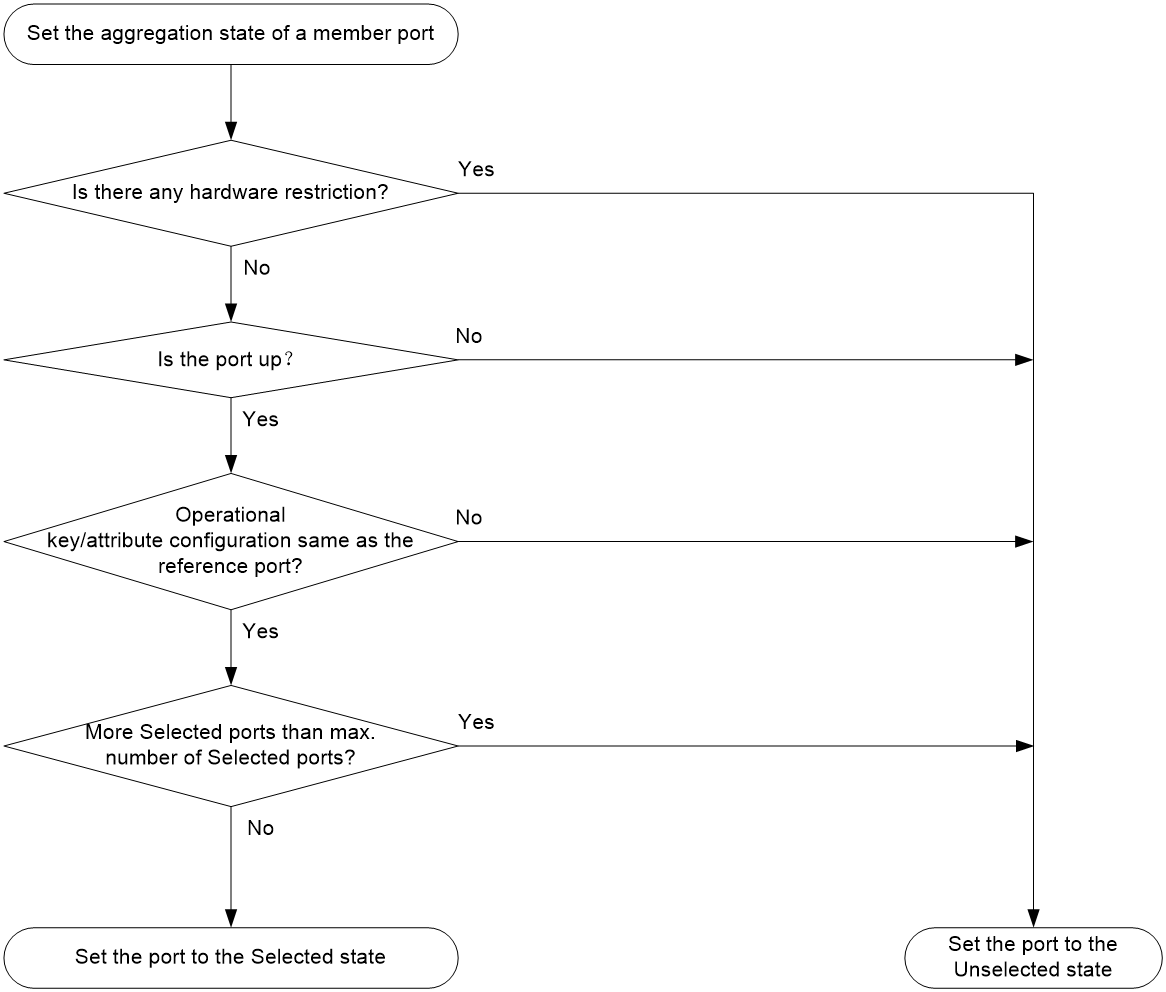
After the limit on Selected ports is reached, the aggregation state of a new member port varies by following conditions:
· The port is placed in Unselected state if the port and the Selected ports have the same port priority. This mechanism prevents traffic interruption on the existing Selected ports. A device reboot can cause the device to recalculate the aggregation states of member ports.
· The port is placed in Selected state when the following conditions are met:
¡ The port and the Selected ports have different port priorities, and the port has a higher port priority than a minimum of one Selected port.
¡ The port has the same attribute configurations as the aggregate interface.
Any operational key or attribute configuration change might affect the aggregation states of link aggregation member ports.
Dynamic link aggregation
About LACP
Dynamic aggregation is implemented through IEEE 802.3ad Link Aggregation Control Protocol (LACP).
LACP uses LACPDUs to exchange aggregation information between LACP-enabled devices. Each member port in a dynamic aggregation group can exchange information with its peer. When a member port receives an LACPDU, it compares the received information with information received on the other member ports. In this way, the two systems reach an agreement on which ports are placed in Selected state.
LACP functions
LACP offers basic LACP functions and extended LACP functions, as described in Table 2.
Table 2 Basic and extended LACP functions
|
Category |
Description |
|
Basic LACP functions |
Implemented through the basic LACPDU fields, including the LACP system priority, system MAC address, port priority, port number, and operational key. |
|
Extended LACP functions |
Implemented by extending the LACPDU with new TLV fields. Extended LACP can implement LACP MAD for the IRF feature. For more information about IRF and the LACP MAD mechanism, see Virtual Technologies Configuration Guide. The device can participate in LACP MAD as either an IRF member device or an intermediate device. |
LACP operating modes
LACP can operate in active or passive mode.
When LACP is operating in passive mode on a local member port and its peer port, both ports cannot send LACPDUs. When LACP is operating in active mode on either end of a link, both ports can send LACPDUs.
LACP priorities
LACP priorities include LACP system priority and port priority, as described in Table 3. The smaller the priority value, the higher the priority.
|
Type |
Description |
|
LACP system priority |
Used by two peer devices (or systems) to determine which one is superior in link aggregation. In dynamic link aggregation, the system that has higher LACP system priority sets the Selected state of member ports on its side. The system that has lower priority sets the aggregation state of local member ports the same as their respective peer ports. |
|
Port priority |
Determines the likelihood of a member port to be a Selected port on a system. A port with a higher port priority is more likely to become Selected. |
LACP timeout interval
The LACP timeout interval specifies how long a member port waits to receive LACPDUs from the peer port. If a local member port has not received LACPDUs from the peer in 3 seconds after the LACP timeout interval expires, the member port considers the peer as failed.
The LACP timeout interval also determines the LACPDU sending rate of the peer. LACP timeout intervals include the following types:
· Short timeout interval—3 seconds. If you use the short timeout interval, the peer sends one LACPDU per second.
· Long timeout interval—90 seconds. If you use the long timeout interval, the peer sends one LACPDU every 30 seconds.
Methods to assign interfaces to a dynamic link aggregation group
You can use one of the following methods to assign interfaces to a dynamic link aggregation group:
· Manual assignment—Manually assign interfaces to the dynamic link aggregation group.
· Automatic assignment—Enable automatic assignment on interfaces to have them automatically join a dynamic link aggregation group depending on the peer information in the received LACPDUs.
|
|
NOTE: When you use automatic assignment on one end, you must use manual assignment on the other end. |
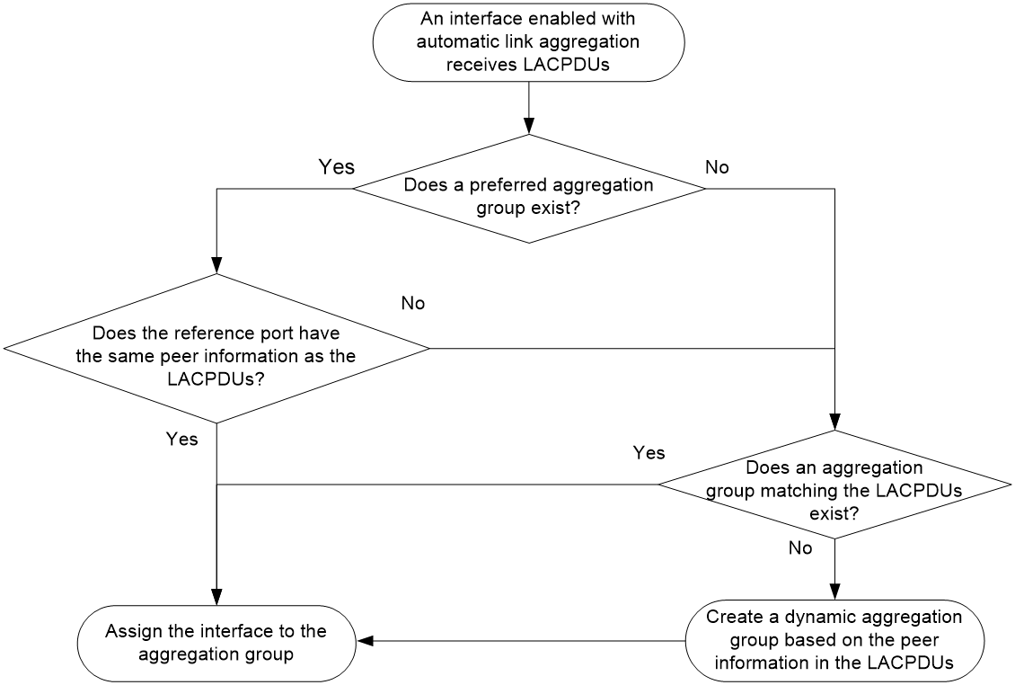
Automatic member port assignment
This feature automates the assignment of aggregation member ports to an aggregation group. You can use this feature when setting up an aggregate link to a server.
As shown in Figure 3, an interface enabled with automatic assignment joins a dynamic aggregation group based on the peer information in the LACPDUs received from the aggregation peer. If none of the existing dynamic aggregation groups is qualified, the device automatically creates a new dynamic aggregation group, Then, the device assigns the interface to that group and synchronizes the interface's attribute configurations to the aggregate interface.
A dynamic aggregation group that contains automatically assigned member ports selects a reference port and Selected ports as described in "How dynamic link aggregation works." The assignment methods of member ports do not change the processes of reference port selection and Selected port selection.
Figure 3 Automatic member port assignment process
How dynamic link aggregation works
Choosing a reference port
The system chooses a reference port from the member ports in up state. A Selected port must have the same operational key and attribute configurations as the reference port.
The local system (the actor) and the peer system (the partner) negotiate a reference port by using the following workflow:
1. The two systems determine the system with the smaller system ID.
A system ID contains the LACP system priority and the system MAC address.
a. The two systems compare their LACP priority values.
The lower the LACP priority, the smaller the system ID. If the LACP priority values are the same, the two systems proceed to step b.
b. The two systems compare their MAC addresses.
The lower the MAC address, the smaller the system ID.
2. The system with the smaller system ID chooses the port with the smallest port ID as the reference port.
A port ID contains a port priority and a port number. The lower the port priority, the smaller the port ID.
a. The system chooses the port with the lowest priority value as the reference port.
If the ports have the same priority, the system proceeds to step b.
b. The system compares their port numbers.
The smaller the port number, the smaller the port ID.
The port with the smallest port number and the same attribute configurations as the aggregate interface is chosen as the reference port.
|
|
NOTE: To identify the port numbers of aggregation member ports, execute the display link-aggregation verbose command and examine the Index field in the command output. |
Setting the aggregation state of each member port
After the reference port is chosen, the system with the smaller system ID sets the state of each member port on its side.
Figure 4 Setting the state of a member port in a dynamic aggregation group
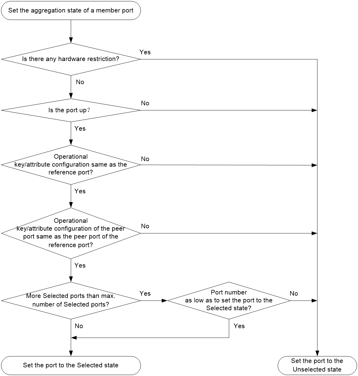
The system with the greater system ID can detect the aggregation state changes on the peer system. The system with the greater system ID sets the aggregation state of local member ports the same as their peer ports.
When you aggregate interfaces in dynamic mode, follow these guidelines:
· A dynamic link aggregation group chooses only full-duplex ports as the Selected ports.
· For stable aggregation and service continuity, do not change the operational key or attribute configurations on any member port.
· When a member port changes to the Selected or Unselected state, its peer port changes to the same aggregation state.
· After the Selected port limit is reached, a newly joining port becomes a Selected port if it is more eligible than a current Selected port.
Edge aggregate interface
Dynamic link aggregation fails on a server-facing aggregate interface if dynamic link aggregation is configured only on the device. The device forwards traffic by using only one of the physical ports that are connected to the server.
To improve link reliability, configure the aggregate interface as an edge aggregate interface. This feature enables all member ports of the aggregation group to forward traffic. When a member port fails, its traffic is automatically switched to other member ports.
After dynamic link aggregation is configured on the server, the device can receive LACPDUs from the server. Then, link aggregation between the device and the server operates correctly.
An edge aggregate interface takes effect only when it is configured on an aggregate interface corresponding to a dynamic aggregation group.
Load sharing modes for link aggregation groups
In a link aggregation group, traffic can be load shared across the Selected ports based on any of the following modes:
· Per-flow load sharing—Distributes traffic on a per-flow basis. The load sharing mode classifies packets into flows and forwards packets of the same flow on the same link. This mode can be one of or a combination of the following traffic classification criteria:
¡ Ingress port.
¡ Source or destination IP.
¡ Source or destination MAC.
¡ Source or destination port number.
¡ MPLS label.
· Per-packet load sharing—Distributes traffic on a per-packet basis.
· Automatic load sharing—Automatically selects a load sharing mode depending on the packet type. For example, the load sharing mode differs between IPv4 packets and Layer 2 packets. This mode is also called the flexible mode.
· Intelligent load sharing—Distributes traffic based on the bandwidth usage of Selected member ports. In this mode, the device periodically samples the bandwidth usage of Selected member ports and adjusts traffic distribution if the bandwidth usage of a Selected member port exceeds a threshold. The threshold varies by device model. After you set the intelligent load sharing mode, the device distributes traffic based on the default load sharing mode and then optimizes traffic distribution based on the bandwidth usage.
· Resilient load sharing—Redistributes as less traffic as possible when a link state change occurs to minimize its impact on services. In this mode, an aggregation group distributes traffic based on the default load sharing mode when no link change occurs. When a link fails, the system rehashes the traffic on the failed link across the remaining Selected links. Because the existing traffic on the Selected links is not rehashed as in other modes, impact on the ongoing services is minimized. When the failed link recovers, the system rehashes part of the traffic on the existing Selected links to the recovered link. Because not all traffic is rehashed, the traffic distribution pattern might differ from what it was before the link failure.
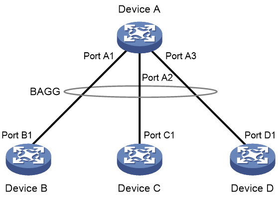
S-MLAG
Simple multichassis link aggregation (S-MLAG) enhances dynamic link aggregation to establish an aggregation that spans multiple standalone devices to a remote device.
An S-MLAG multichassis aggregation connects one dynamic Layer 2 aggregate interface on each S-MLAG device to the remote device, as shown in Figure 5.
S-MLAG uses an S-MLAG group to manage the aggregate interfaces for each aggregation, and it runs LACP to maintain each aggregation as does dynamic link aggregation. To the remote device, the S-MLAG devices appear as one peer aggregation system.
Use S-MLAG only to establish aggregate links with servers.
Figure 5 S-MLAG application scenario
Restrictions and guidelines: Mixed use of manual and automatic link aggregation configuration
To avoid unexpected aggregation issues, do not use manual assignment, automatic assignment, and automatic link aggregation in any combination. If you use any two of these features in combination, an automatically assigned member port might move between aggregation groups or undesirably change from Selected to Unselected in some situations.
For a mirroring group, do not assign the source port to an aggregation group other than the one that accommodates the destination port, egress port, or reflector port. If the source port is in a different aggregation group than the other ports, mirrored LACPDUs will be transmitted between the aggregation groups and cause aggregate interface flapping.
On an M-LAG system with multislot link aggregation configured, the number of MAC addresses learned on the M-LAG member devices varies by the load sharing state:
· If the M-LAG member devices do not load share traffic, the traffic will be distributed to one of the M-LAG member devices. When an M-LAG member device learns MAC address entries, it sends these entries to the peer M-LAG member device. In this scenario, the M-LAG member devices have the same number of MAC addresses.
· If the M-LAG member devices load share the traffic evenly or unevenly, the traffic will be distributed to both M-LAG member devices. When an M-LAG member device learns MAC address entries, it sends these entries to the peer M-LAG member device.
¡ If hash conflict occurs during the MAC address synchronization, the M-LAG member devices can learn a maximum of twice the number of MAC addresses learned on one M-LAG member device. If the M-LAG member devices learn the same MAC addresses, the total number of learned MAC addresses equals the number of MAC addresses learned on one M-LAG member device.
¡ If no hash conflict occurs, the M-LAG member devices learn twice the number of MAC addresses learned on one M-LAG member device.
Ethernet link aggregation tasks at a glance
To configure Ethernet link aggregation, perform the following tasks:
2. Configuring link aggregations
¡ Configuring a manual link aggregation
3. (Optional.) Configuring an aggregate interface
¡ Configuring the description of an aggregate interface
¡ Setting the MAC address for an aggregate interface
¡ Configuring jumbo frame support
¡ Setting the MTU for a Layer 3 aggregate interface
¡ Setting the expected bandwidth for an aggregate interface
¡ Configuring an edge aggregate interface
An edge aggregate interface uses all member ports to forward traffic when the aggregation peer is not enabled with dynamic link aggregation.
¡ Configuring physical state change suppression on an aggregate interface
¡ Shutting down an aggregate interface
¡ Restoring the default settings for an aggregate interface
4. (Optional.) Adjusting aggregation states of link aggregation member ports
¡ Setting the minimum and maximum numbers of Selected ports for an aggregation group
¡ Ignoring port speed in setting the aggregation states of member ports
¡ Specifying ignored VLANs for a Layer 2 aggregate interface
To have the system ignore the permit state and tagging mode of a VLAN when it decides Selected ports, perform this task.
5. (Optional.) Configuring load sharing for link aggregation groups
¡ Setting static load sharing modes for link aggregation groups
¡ Setting a dynamic load sharing mode for a link aggregation group
¡ Specifying ignored packet fields for default link-aggregation load sharing
¡ Enabling local-first load sharing for link aggregation
¡ Configuring link aggregation load sharing algorithm settings
¡ Setting a hash offset to adjust the load balancing results on link aggregations
¡ Setting the load sharing mode for tunneled traffic
6. (Optional.) Optimizing traffic forwarding
¡ Specifying link aggregation management VLANs and link aggregation management port
Perform this task to enable an aggregation group to forward Layer 3 data traffic of some VLANs through a specific member port.
¡ Excluding a subnet from load sharing on aggregate links
Perform this task to make sure the bidirectional traffic of a subnet traverses the same member port in an aggregation group.
¡ Enabling a Layer 2 aggregate interface to reflect incoming packets back
Perform this task to have a Layer 2 aggregate interface reflect a packet back when it is both the incoming and outgoing interfaces of that packet.
¡ Enabling link-aggregation traffic redirection
This feature redirects traffic on an unavailable Selected port to the remaining available Selected ports of an aggregation group to avoid traffic interruption.
¡ Isolating aggregate interfaces on the device
7. (Optional.) Enabling BFD for an aggregation group
Configuring the system ID
About this task
The two ends of a dynamic aggregate link choose a reference port from the end with a smaller system ID.
The system ID contains the LACP system priority and LACP system MAC address. Two devices use the following rules to compare their system IDs:
· If their system IDs contain different LACP system priorities, the system ID with a smaller LACP system priority value is smaller.
· If their system IDs contain the same LACP system priority, the system ID with a lower LACP system MAC address is smaller.
To view the LACP system MAC address and LACP system priority, execute the display link-aggregation verbose command.
You can configure the system ID globally and in aggregate interface view. The global system ID takes effect on all aggregation groups, and an aggregate-interface-specific system ID takes precedence over the global system ID.
Restrictions and guidelines
Member devices in an S-MLAG system must use the same LACP system priority and LACP system MAC address.
On an M-LAG system, M-LAG interfaces in the same M-LAG group must use the same LACP system MAC address.
For member ports to be selected correctly, do not modify the LACP system priority and LACP system MAC address after a dynamic link aggregation is established.
Procedure
1. Enter system view.
system-view
2. Set the LACP system MAC address globally.
lacp system-mac mac-address
By default, the LACP system MAC address is the bridge MAC address of the device.
3. Set the LACP system priority globally.
lacp system-priority priority
By default, the LACP system priority is 32768.
4. Enter aggregate interface view.
¡ Enter Layer 2 aggregate interface view.
interface bridge-aggregation interface-number
¡ Enter Layer 3 aggregate interface view.
interface route-aggregation interface-number
5. Set the LACP system MAC address on the aggregate interface.
port lacp system-mac mac-address
By default, the LACP system MAC address is the bridge MAC address of the device.
6. Set the LACP system priority on the aggregate interface.
port lacp system-priority priority
By default, the LACP system priority is 32768.
Configuring a manual link aggregation
Restrictions and guidelines for aggregation group configuration
Layer 2 aggregation group restrictions
You cannot assign an interface to a Layer 2 aggregation group if any features in Table 4 are configured on that interface.
Table 4 Features incompatible with Layer 2 aggregation member ports
|
Feature on the interface |
Reference |
|
Forcibly bringing up a fiber port by using the port up-mode command |
"Configuring Ethernet interfaces" |
|
MAC authentication |
MAC authentication in Security Configuration Guide |
|
Port security |
Port security in Security Configuration Guide |
|
802.1X |
802.1X in Security Configuration Guide |
Aggregation member port restrictions
Deleting an aggregate interface also deletes its aggregation group and causes all member ports to leave the aggregation group.
If an interface has different attribute configurations from the aggregate interface, the interface cannot join the aggregation group.
After joining an aggregation group, an interface inherits the attribute configurations on the aggregate interface. You can modify the attribute configurations only on the aggregate interface.
After an interface leaves an aggregation group, VLAN settings on the interface will not be restored to the default.
To avoid a loop, shut down an interface before removing the interface from an aggregation group.
After a reference port leaves a dynamic aggregation group, you must remove its peer port from the aggregation group. This restriction ensures that the local port can be assigned to another aggregation group.
Do not assign a reflector port for port mirroring to an aggregation group. For more information about reflector ports, see Network Management and Monitoring Configuration Guide.
You cannot assign monitor ports for port mirroring to an aggregation group.
Attribute and protocol configuration restrictions
For a link aggregation, attribute configurations are configurable only on the aggregate interface and are automatically synchronized to all member ports. You cannot configure attribute configurations on a member port until it is removed from the link aggregation group. After the aggregate interface is deleted, the settings that have been synchronized from the aggregate interface are retained on the member ports.
If an attribute setting on the aggregate interface fails to be synchronized to a Selected member port, the port might change to the Unselected state.
The protocol configurations for an aggregate interface take effect only on the current aggregate interface. The protocol configurations for a member port take effect only when the port leaves its aggregation group.
Configuration consistency requirements
You must configure the same aggregation mode at the two ends of an aggregate link.
· For a successful static aggregation, make sure the ports at both ends of each link are in the same aggregation state.
· For a successful dynamic aggregation:
¡ Make sure the ports at both ends of a link are assigned to the correct aggregation group. The two ends can automatically negotiate the aggregation state of each member port.
¡ If you use automatic interface assignment on one end, you must use manual assignment on the other end.
Configuring a Layer 2 aggregation group
Configuring a Layer 2 static aggregation group
1. Enter system view.
system-view
2. Create a Layer 2 aggregate interface and enter Layer 2 aggregate interface view.
interface bridge-aggregation interface-number
When you create a Layer 2 aggregate interface, the system automatically creates a Layer 2 static aggregation group numbered the same as that interface.
3. Return to system view.
quit
4. Assign an interface to the Layer 2 aggregation group:
a. Enter Layer 2 Ethernet interface view.
interface interface-type interface-number
b. Assign the interface to the Layer 2 aggregation group.
port link-aggregation group group-id [ force ]
Repeat the substeps to assign more interfaces to the aggregation group.
To synchronize the attribute configurations from the aggregate interface when the current interface joins the aggregation group, specify the force keyword.
5. (Optional.) Set the port priority of the interface.
link-aggregation port-priority priority
The default port priority of an interface is 32768.
Configuring a Layer 2 dynamic aggregation group
1. Enter system view.
system-view
2. Create a Layer 2 aggregate interface and enter Layer 2 aggregate interface view.
interface bridge-aggregation interface-number
When you create a Layer 2 aggregate interface, the system automatically creates a Layer 2 static aggregation group numbered the same as that interface.
3. Configure the aggregation group to operate in dynamic mode.
link-aggregation mode dynamic
By default, an aggregation group operates in static mode.
4. Return to system view.
quit
5. Assign an interface to the Layer 2 aggregation group:
a. Enter Layer 2 Ethernet interface view.
interface interface-type interface-number
b. Assign the interface to the Layer 2 aggregation group or enable automatic assignment on that interface.
port link-aggregation group { group-id [ force ] | auto [ group-id ] }
Repeat these two substeps to assign more Layer 2 Ethernet interfaces to the aggregation group.
To synchronize the attribute configurations from the aggregate interface when the current interface joins the aggregation group, specify the force keyword.
To enable automatic assignment, specify the auto keyword. As a best practice, do not modify the configuration on an automatically created aggregate interface or its member ports.
6. Set the LACP operating mode for the interface.
¡ Set the LACP operating mode to passive.
lacp mode passive
¡ Set the LACP operating mode to active.
undo lacp mode
By default, LACP is operating in active mode.
7. (Optional.) Set the port priority for the interface.
link-aggregation port-priority priority
The default setting is 32768.
8. (Optional.) Set the short LACP timeout interval (3 seconds) for the interface.
lacp period short
By default, the long LACP timeout interval (90 seconds) is used by the interface.
To avoid traffic interruption during an ISSU, do not set the short LACP timeout interval before performing the ISSU. For more information about ISSU, see Fundamentals Configuration Guide.
Configuring a Layer 3 aggregation group
Configuring a Layer 3 static aggregation group
1. Enter system view.
system-view
2. Create a Layer 3 aggregate interface and enter Layer 3 aggregate interface view.
interface route-aggregation interface-number
When you create a Layer 3 aggregate interface, the system automatically creates a Layer 3 static aggregation group numbered the same as that interface.
3. Return to system view.
quit
4. Assign an interface to the Layer 3 aggregation group:
a. Enter Layer 3 Ethernet interface view.
interface interface-type interface-number
b. Assign the interface to the Layer 3 aggregation group.
port link-aggregation group group-id
Repeat the substeps to assign more interfaces to the aggregation group.
5. (Optional.) Set the port priority of the interface.
link-aggregation port-priority priority
The default port priority of an interface is 32768.
Configuring a Layer 3 dynamic aggregation group
1. Enter system view.
system-view
2. Create a Layer 3 aggregate interface and enter Layer 3 aggregate interface view.
interface route-aggregation interface-number
When you create a Layer 3 aggregate interface, the system automatically creates a Layer 3 static aggregation group numbered the same as that interface.
3. Configure the aggregation group to operate in dynamic mode.
link-aggregation mode dynamic
By default, an aggregation group operates in static mode.
4. Return to system view.
quit
5. Assign an interface to the Layer 3 aggregation group:
a. Enter Layer 3 Ethernet interface view.
interface interface-type interface-number
b. Assign the interface to the Layer 3 aggregation group or enable automatic assignment on that interface.
port link-aggregation group { group-id | auto [ group-id ] }
Repeat these two substeps to assign more Layer 3 Ethernet interfaces to the aggregation group.
To enable automatic assignment, specify the auto keyword. As a best practice, do not modify the configuration on an automatically created aggregate interface or its member ports.
6. Set the LACP operating mode for the interface.
¡ Set the LACP operating mode to passive.
lacp mode passive
¡ Set the LACP operating mode to active.
undo lacp mode
By default, LACP is operating in active mode.
7. (Optional.) Set the port priority of the interface.
link-aggregation port-priority priority
The default setting is 32768.
8. (Optional.) Set the short LACP timeout interval (3 seconds) for the interface.
lacp period short
By default, the long LACP timeout interval (90 seconds) is used by the interface.
To avoid traffic interruption during an ISSU, do not set the short LACP timeout interval before performing the ISSU. For more information about ISSU, see Fundamentals Configuration Guide.
Configuring a Layer 3 aggregate subinterface
1. Enter system view.
system-view
2. Create a Layer 3 aggregate subinterface, and enter Layer 3 aggregate subinterface view.
interface route-aggregation interface-number.subnumber
Configuring S-MLAG
Restrictions and guidelines
Use S-MLAG only to establish aggregate links with servers.
S-MLAG is intended for a non-IRF environment. Do not configure it on an IRF fabric. For more formation about IRF, see Virtual Technologies Configuration Guide.
Each S-MLAG group can contain only one aggregate interface on each device.
The aggregate interfaces in an S-MLAG group cannot be used as M-LAG interfaces or M-LAG peer-link interfaces. For more information about M-LAG interfaces and peer-link interfaces, see M-LAG configuration in Layer 2—LAN Switching Configuration Guide.
On S-MLAG devices, make sure the member ports in an aggregation group have the same speed and duplex mode. Inconsistency in these settings might cause reference port reselection and interrupt traffic forwarding when new member ports join the aggregation group.
Do not configure the following settings on S-MLAG devices:
· LACP MAD.
· Link-aggregation traffic redirection.
· Maximum or minimum number of Selected ports.
· Automatic member port assignment.
· Ignoring port speed in setting the aggregation states of member ports.
· Spanning tree. For more information, see "Configuring spanning tree protocols."
As a best practice, maintain consistency across S-MLAG devices in service feature configuration.
Prerequisites
Configure the link aggregation settings other than S-MLAG settings on each S-MLAG device. Make sure the settings are consistent across the S-MLAG devices.
Procedure
1. Enter system view.
system-view
2. Set the LACP system MAC address.
lacp system-mac mac-address
By default, the LACP system MAC address is the bridge MAC address of the device.
All S-MLAG devices must use the same LACP system MAC address.
3. Set the LACP system priority.
lacp system-priority priority
By default, the LACP system priority is 32768.
All S-MLAG devices must use the same LACP system priority.
4. Set the LACP system number.
lacp system-number number
By default, the LACP system number is not set.
You must assign a unique LACP system number to each S-MLAG device.
5. Enter Layer 2 aggregate interface view.
interface bridge-aggregation interface-number
6. Set the link aggregation mode to dynamic.
link-aggregation mode dynamic
By default, an aggregation group operates in static mode.
7. Assign the aggregate interface to an S-MLAG group.
port s-mlag group group-id
By default, an aggregate interface is not assigned to any S-MLAG group.
Configuring an aggregate interface
Most settings that can be made on Layer 2 or Layer 3 Ethernet interfaces can also be made on Layer 2 or Layer 3 aggregate interfaces.
Configuring the description of an aggregate interface
About this task
You can configure the description of an aggregate interface for administration purposes, for example, describing the purpose of the interface.
Procedure
1. Enter system view.
system-view
2. Enter aggregate interface view.
¡ Enter Layer 2 aggregate interface view.
interface bridge-aggregation interface-number
¡ Enter Layer 3 aggregate interface view.
interface route-aggregation interface-number
¡ Enter Layer 3 aggregate subinterface view.
interface route-aggregation interface-number.subnumber }
3. Configure the interface description.
description text
By default, the description of an interface is interface-name Interface.
Setting the MAC address for an aggregate interface
About this task
Typically, all aggregate interfaces on a device use the same MAC address, and aggregate interfaces on different devices use different MAC addresses. However, you must set different MAC addresses for aggregate interfaces on a device in some situations.
Procedure
1. Enter system view.
system-view
2. Enter aggregate interface view.
¡ Enter Layer 3 aggregate interface view.
interface route-aggregation interface-number
¡ Enter Layer 3 aggregate subinterface view.
interface route-aggregation interface-number.subnumber
3. Set the MAC address for the aggregate interface.
mac-address mac-address
By default, all Layer 3 aggregate interfaces and subinterfaces on the device use the same default MAC address.
Configuring jumbo frame support
About this task
An aggregate interface might receive frames larger than 1536 bytes during high-throughput data exchanges, such as file transfers. These frames are called jumbo frames.
How an aggregate interface processes jumbo frames depends on whether jumbo frame support is enabled on the interface.
· If configured to deny jumbo frames, the aggregate interface discards jumbo frames.
· If enabled with jumbo frame support, the aggregate interface performs the following operations:
¡ Processes jumbo frames that are within the allowed length.
¡ Discards jumbo frames that exceed the allowed length.
Procedure
1. Enter system view.
system-view
2. Enter aggregate interface view.
¡ Enter Layer 2 aggregate interface view.
interface bridge-aggregation interface-number
¡ Enter Layer 3 aggregate interface view.
interface route-aggregation interface-number
3. Allow jumbo frames.
jumboframe enable [ size ]
By default, an aggregate interface allows jumbo frames with a maximum length of 9416 bytes to pass through.
If you execute this command multiple times, the most recent configuration takes effect.
Setting the MTU for a Layer 3 aggregate interface
About this task
The MTU of an interface affects IP packets fragmentation and reassembly on the interface.
Procedure
1. Enter system view.
system-view
2. Enter Layer 3 aggregate interface or subinterface view.
interface route-aggregation { interface-number | interface-number.subnumber }
3. Set the MTU.
mtu size
The default setting is 1500 bytes.
Setting the expected bandwidth for an aggregate interface
About this task
Expected bandwidth is an informational parameter used only by higher-layer protocols for calculation. You cannot adjust the actual bandwidth of an interface by performing this task.
Procedure
1. Enter system view.
system-view
2. Enter aggregate interface view.
¡ Enter Layer 2 aggregate interface view.
interface bridge-aggregation interface-number
¡ Enter Layer 3 aggregate interface view.
interface route-aggregation interface-number
¡ Enter Layer 3 aggregate subinterface view.
interface route-aggregation interface-number.subnumber }
3. Set the expected bandwidth for the interface.
bandwidth bandwidth-value
By default, the expected bandwidth (in kbps) is the interface baud rate divided by 1000.
Configuring an edge aggregate interface
Restrictions and guidelines
This configuration takes effect only on aggregate interfaces in dynamic mode.
Link-aggregation traffic redirection cannot operate correctly on an edge aggregate interface. For more information about link-aggregation traffic redirection, see "Enabling link-aggregation traffic redirection."
Procedure
1. Enter system view.
system-view
2. Enter aggregate interface view.
¡ Enter Layer 2 aggregate interface view.
interface bridge-aggregation interface-number
¡ Enter Layer 3 aggregate interface view.
interface route-aggregation interface-number
3. Configure the aggregate interface as an edge aggregate interface.
lacp edge-port
By default, an aggregate interface does not operate as an edge aggregate interface.
Configuring physical state change suppression on an aggregate interface
About this task
The physical link state of an aggregate interface is either up or down. Each time the physical link of an interface comes up or goes down, the system immediately reports the change to the CPU. The CPU then notifies the upper-layer protocol modules (such as routing and forwarding modules) of the change, and the device automatically generates traps and log messages and sends them to the SNMP and information center modules. You can configure SNMP and information center to output these messages.
To prevent frequent physical link flapping from affecting system performance, configure physical state change suppression. You can configure this feature to suppress link-down events, link-up events, or both. If an event of the specified type still exists when the suppression interval expires, the system reports the event to the CPU.
Restrictions and guidelines
When you configure suppression interval settings on an aggregate interface, make sure its peer interface is also an aggregate interface in the same aggregation mode. In addition, the suppression interval settings must be the same between the peer aggregate interfaces.
As a best practice, use the default setting in an S-MLAG environment.
On an interface, you can configure different suppression intervals for link-up and link-down events. If you execute the link-delay command multiple times for an event type, the most recent configuration takes effect on that event type.
Use this feature on an aggregate interface to reduce the impact of interface flapping on upper-layer services, for example, on an M-LAG peer-link interface. For more information about peer-link interfaces, see "Configuring M-LAG."
Procedure
1. Enter system view.
system-view
2. Enter aggregate interface view.
¡ Enter Layer 2 aggregate interface view.
interface bridge-aggregation interface-number
¡ Enter Layer 3 aggregate interface view.
interface route-aggregation interface-number
3. Configure physical state change suppression.
link-delay { down | up } [ msec ] delay-time
By default, each time the physical link of an aggregate interface goes up or comes down, the system immediately reports the change to the CPU.
Shutting down an aggregate interface
Restrictions and guidelines
Shutting down or bringing up an aggregate interface affects the aggregation states and link states of member ports in the corresponding aggregation group as follows:
· When an aggregate interface is shut down, all its Selected ports become Unselected and all member ports go down.
· When an aggregate interface is brought up, the aggregation states of all its member ports are recalculated.
When you shut down or bring up a Layer 3 aggregate interface, all its aggregate subinterfaces are also shut down or brought up. Shutting down or bringing up a Layer 3 aggregate subinterface does not affect the state of the main aggregate interface.
Procedure
1. Enter system view.
system-view
2. Enter aggregate interface view.
¡ Enter Layer 2 aggregate interface view.
interface bridge-aggregation interface-number
¡ Enter Layer 3 aggregate interface view.
interface route-aggregation interface-number
¡ Enter Layer 3 aggregate subinterface view.
interface route-aggregation interface-number.subnumber }
3. Shut down the interface.
shutdown
|
|
CAUTION: The shutdown command will disconnect all links established on an interface. Make sure you are fully aware of the impacts of this command when you use it on a live network. |
Restoring the default settings for an aggregate interface
Restrictions and guidelines
|
|
CAUTION: The default command might interrupt ongoing network services. Make sure you are fully aware of the impacts of this command when you execute it on a live network. |
The default command might fail to restore the default settings for some commands for reasons such as command dependencies and system restrictions.
To resolve this issue:
1. Use the display this command in interface view to identify these commands.
2. Use their undo forms or follow the command reference to restore their default settings.
3. If the restoration attempt still fails, follow the error message instructions to resolve the issue.
Procedure
1. Enter system view.
system-view
2. Enter aggregate interface view.
¡ Enter Layer 2 aggregate interface view.
interface bridge-aggregation interface-number
¡ Enter Layer 3 aggregate interface view.
interface route-aggregation interface-number
¡ Enter Layer 3 aggregate subinterface view.
interface route-aggregation interface-number.subnumber }
3. Restore the default settings for the aggregate interface.
Default
Setting the minimum and maximum numbers of Selected ports for an aggregation group
About this task
The bandwidth of an aggregate link increases as the number of Selected member ports increases. To avoid congestion, you can set the minimum number of Selected ports required for bringing up an aggregate interface.
This minimum threshold setting affects the aggregation states of aggregation member ports and the state of the aggregate interface.
· When the number of member ports eligible to be Selected ports is smaller than the minimum threshold, the following events occur:
¡ The eligible member ports are placed in Unselected state.
¡ The link layer state of the aggregate interface becomes down.
· When the number of member ports eligible to be Selected ports reaches or exceeds the minimum threshold, the following events occur:
¡ The eligible member ports are placed in Selected state.
¡ The link layer state of the aggregate interface becomes up.
The maximum number of Selected ports allowed in an aggregation group is limited by either manual configuration or hardware limitation, whichever value is smaller.
You can implement backup between two ports by performing the following tasks:
· Assigning two ports to an aggregation group.
· Setting the maximum number of Selected ports to 1 for the aggregation group.
Then, only one Selected port is allowed in the aggregation group, and the Unselected port acts as a backup port.
Restrictions and guidelines
|
|
IMPORTANT: After you set the minimum percentage of Selected ports for an aggregation group, aggregate interface flapping might occur when ports join or leave an aggregation group. Make sure you are fully aware of the impacts of this setting when you configure it on a live network. |
You can set either the minimum number or the minimum percentage of Selected ports for an aggregation group. If you configure both settings on an aggregate interface, the higher Selected port number limit takes effect.
The minimum and maximum numbers of Selected ports must be the same between the two ends of an aggregate link.
The minimum percentage of Selected ports must be the same between the two ends of an aggregate link.
For an aggregation group, the maximum number of Selected ports must be equal to or higher than the minimum number of Selected ports. If you set the minimum percentage of Selected ports for the aggregation group, do not set the maximum number of Selected ports. If you set the maximum number of Selected ports, the calculated minimum number of Selected ports might be larger than the maximum number of Selected ports.
Procedure
1. Enter system view.
system-view
2. Enter aggregate interface view.
¡ Enter Layer 2 aggregate interface view.
interface bridge-aggregation interface-number
¡ Enter Layer 3 aggregate interface view.
interface route-aggregation interface-number
3. Set the minimum number of Selected ports for the aggregation group. Choose one of the following methods:
¡ Set the minimum number of Selected ports.
link-aggregation selected-port minimum min-number
¡ Set the minimum percentage of Selected ports.
link-aggregation selected-port minimum percentage number
By default, the minimum number of Selected ports is not specified for an aggregation group.
4. Set the maximum number of Selected ports for the aggregation group.
link-aggregation selected-port maximum max-number [ lacp-sync ]
By default, an aggregation group can have a maximum of 256 Selected ports.
For a static aggregate link, you must set the maximum number of Selected ports to the same value at its two ends.
For a dynamic aggregate link, you must set the maximum number of Selected ports to the same value at its two ends if you do not specify the lacp-sync keyword. If you specify this keyword, the two ends of the aggregate link compare their maximum Selected port number settings and use the smaller value.
Disabling the default action of selecting a Selected port for dynamic aggregation groups that have not received LACPDUs
About this task
The default port selection action applies to dynamic aggregation groups.
This action automatically chooses the port with the lowest ID from among all up member ports as a Selected port if none of them has received LACPDUs before the LACP timeout interval expires.
After this action is disabled, a dynamic aggregation group will not have any Selected ports to forward traffic if it has not received LACPDUs before the LACP timeout interval expires.
Procedure
1. Enter system view.
system-view
2. Disable the default port selection action.
lacp default-selected-port disable
By default, the default port selection action is enabled for dynamic aggregation groups.
Configuring a dynamic aggregation group to use port speed as the prioritized criterion for reference port selection
About this task
Perform this task to ensure that a dynamic aggregation group selects a high-speed member port as the reference port. After you perform this task, the reference port will be selected based on the criteria in order of device ID, port speed, and port ID.
Restrictions and guidelines
Changing reference port selection criteria might cause transient traffic interruption. Make sure you understand the impact of this task on your network.
As a best practice, shut down the peer aggregate interfaces before you execute this command and bring up the interfaces after this command is executed on both of them.
Procedure
1. Enter system view.
system-view
2. Enter aggregate interface view.
¡ Enter Layer 2 aggregate interface view.
interface bridge-aggregation interface-number
¡ Enter Layer 3 aggregate interface view.
interface route-aggregation interface-number
3. Specify port speed as the prioritized criterion for reference port selection.
lacp select speed
By default, port ID is the prioritized criterion for reference port selection of a dynamic aggregation group.
Ignoring port speed in setting the aggregation states of member ports
About this task
This feature allows ports at a different speed than the reference port to become Selected by ignoring the port speed during operational key calculation.
You must configure the same port speed ignoring setting at the two ends of a static configuration to ensure that the peer ports are placed in the same aggregation state. This requirement does not apply to a dynamic aggregation, on which the two ends negotiate the aggregation state of the peer ports automatically.
Restriction and guidelines
Make sure you are fully aware of the impacts of this feature when you use it on a live network.
· When you execute the link-aggregation ignore speed command or its undo form, the operational key changes and the aggregate interface flaps temporarily.
· The link-aggregation ignore speed command might cause traffic loss on Selected ports operating at a speed lower than the other Selected ports in the aggregation group when traffic is distributed among the ports.
Procedure
1. Enter system view.
system-view
2. Enter aggregate interface view.
¡ Enter Layer 2 aggregate interface view.
interface bridge-aggregation interface-number
¡ Enter Layer 3 aggregate interface view.
interface route-aggregation interface-number
3. Configure the aggregation group to ignore port speed in setting the aggregation states of member ports.
link-aggregation ignore speed
By default, an aggregation group does not ignore port speed in setting the aggregation states of member ports.
Specifying ignored VLANs for a Layer 2 aggregate interface
About this task
By default, you cannot add a port to a Layer 2 link aggregation group if it has a different VLAN permit state or tagging mode than the aggregate interface.
To have a port participate in a Layer 2 aggregation despite its difference with the aggregate interface in the settings of a VLAN, configure that VLAN as an ignored VLAN.
Restrictions and guidelines
This feature takes effect only when the link type of a Layer 2 aggregate interface is hybrid or trunk.
Procedure
1. Enter system view.
system-view
2. Enter Layer 2 aggregate interface view.
interface bridge-aggregation interface-number
3. Specify ignored VLANs.
link-aggregation ignore vlan vlan-id-list
By default, a Layer 2 aggregate interface does not ignore any VLANs.
Configuring load sharing for link aggregation groups
Setting static load sharing modes for link aggregation groups
About this task
You can set the static global or group-specific load sharing mode. A link aggregation group preferentially uses the group-specific load sharing mode. If the group-specific load sharing mode is not available, the group uses the global load sharing mode.
Restrictions and guidelines
The dynamic load sharing mode has priority over the static load sharing mode. If you configure both settings on an aggregate interface, the dynamic mode takes effect.
In system view, the device supports the following load sharing modes:
· Source IP address.
· Destination IP address.
· Source MAC address.
· Destination MAC address.
· Layer 1 MPLS label.
· Layer 2 MPLS label.
· Source IP address and destination IP address.
· Source IP address and source port.
· Destination IP address and destination port.
· Layer 1 MPLS label and Layer 2 MPLS label.
· Source IP address, source port, destination IP address, and destination port.
· Any combination of ingress port, source MAC address, and destination MAC address.
In aggregate interface view, the device supports the following load sharing modes:
· Load sharing mode automatically determined based on the packet type.
· Per-packet.
· Resilient.
· Source IP address.
· Destination IP address.
· Source MAC address.
· Destination MAC address.
· Destination IP address and source IP address.
· Destination MAC address and source MAC address.
When you set the resilient load sharing mode, follow these restrictions and guidelines:
· In this mode, an aggregation group distributes traffic based on the default load sharing mode when no link change occurs.
· When you set the dynamic load sharing mode on an aggregate interface, you cannot set the resilient load sharing mode on all aggregate interfaces.
· To enable resilient load sharing mode on an aggregate interface that has Selected member ports, use the following procedure:
a. Use the shutdown command to shut down the aggregate interface.
b. Enable resilient load sharing mode.
· When you set the resilient load sharing mode on an M-LAG interface, use the following procedures:
c. Enable resilient load sharing mode.
d. Assign the member ports to the M-LAG interface.
· When you set the resilient load sharing mode on a local M-LAG interface or a peer M-LAG interface on which member ports exist, use the following procedures:
e. Delete the M-LAG interface.
f. Recreate an M-LAG interface.
g. Enable resilient load sharing mode on the new M-LAG interface.
For more information about M-LAG interfaces, see "Configuring M-LAG."
Setting the global link-aggregation load sharing mode
1. Enter system view.
system-view
2. Set the global link-aggregation load sharing mode.
link-aggregation global load-sharing mode { { destination-ip | destination-mac | destination-port | ingress-port | mpls-label1 | mpls-label2 | source-ip | source-mac | source-port } *
By default, packets are load shared depending on their packet type, as follows:
¡ Layer 2 frames are load shared based on the source and destination MAC addresses, and EtherType value.
¡ IP packets are load shared based on the source and destination IP addresses, protocol numbers, and source and destination port numbers.
Setting the group-specific load sharing mode
1. Enter system view.
system-view
2. Enter aggregate interface view.
¡ Enter Layer 2 aggregate interface view.
interface bridge-aggregation interface-number
¡ Enter Layer 3 aggregate interface view.
interface route-aggregation interface-number
3. Set the load sharing mode for the aggregation group.
link-aggregation load-sharing mode { { destination-ip | destination-mac | source-ip | source-mac } * | flexible | per-packet | resilient }
By default, group-specific load sharing mode is the same as the global load sharing mode.
Setting a dynamic load sharing mode for a link aggregation group
About this task
An aggregation group does not distribute traffic based on the bandwidth usage of its member ports when using a static load sharing mode. As a result, traffic might be distributed unevenly among the aggregation member ports. To obtain balanced load sharing results, you can use dynamic load sharing to distribute traffic based on the bandwidth usage of aggregation member ports.
Dynamic load sharing supports the following modes:
· Eligible—Distributes the traffic from a flow on a per-flowlet basis. Flowlets are bursts of packets from a flow, which are separated based on the flowlet gap timer. If the forwarding latency between two bursts of packets is larger than the flowlet gap timer, they are two flowlets and can be forwarded on different links. The link selected for a flowlet is the least utilized link at the time of selection.
· Fixed—Distributes traffic across the aggregation member links on a per-flow basis. The link selected for a flow is the least utilized link at the time of selection.
· Spray—Distributes traffic across the aggregation member links on a per-packet basis. The link selected for a packet is the least utilized link at the time of selection.
|
|
IMPORTANT: In spray mode, packets in a flow might be distributed to different links and arrive at the receiving device out of order. When you use this mode, you must make sure the receiving device supports packet reordering. |
Restrictions and guidelines
If you enable resilient load sharing mode on an aggregate interface, you cannot enable dynamic load sharing mode on any aggregate interfaces.
The dynamic load sharing mode has priority over the static load sharing mode. If you configure both settings on an aggregate interface, the dynamic mode takes effect.
Procedure
1. Enter system view.
system-view
2. Enter aggregate interface view.
¡ Enter Layer 2 aggregate interface view.
interface bridge-aggregation interface-number
¡ Enter Layer 3 aggregate interface view.
interface route-aggregation interface-number
3. Configure a dynamic load sharing mode.
link-aggregation load-sharing mode dynamic{ eligible [ flowlet-gap-time flowlet-gap-time ] | fixed | spray }
By default, an aggregation group uses the static load sharing mode.
Specifying ignored packet fields for default link-aggregation load sharing
About this task
To obtain the optimal load distribution performance in the default load sharing mode, you can perform this task to exclude some fields from load sharing calculation.
Procedure
1. Enter system view.
system-view
2. Specify ignored packet fields for default link-aggregation load sharing.
link-aggregation load-sharing ignore { destination-ip | destination-mac | destination-port | ethernet-type | ingress-port | ip-protocol | mpls-label1 | mpls-label2 | mpls-label3 | source-ip | source-mac | source-port | vlan-id } *
By default, no ignored packet fields are specified for default link-aggregation load sharing.
Enabling local-first load sharing for link aggregation
About this task
Use local-first load sharing in a multidevice link aggregation scenario to distribute traffic preferentially across member ports on the ingress slot.
When you aggregate ports on different member devices in an IRF fabric, you can use local-first load sharing to reduce traffic on IRF links, as shown in Figure 6. For more information about IRF, see Virtual Technologies Configuration Guide.
Figure 6 Load sharing for multidevice link aggregation in an IRF fabric
Enabling local-first load sharing for link aggregation globally
1. Enter system view.
system-view
2. Enable local-first load sharing for link aggregation globally.
link-aggregation load-sharing mode local-first
By default, local-first load sharing is enabled globally.
Configuring link aggregation load sharing algorithm settings
About this task
Use the link aggregation load sharing algorithm and hash seed features to optimize traffic distribution on aggregate links when the default load sharing mode is used. Each algorithm represents a CRC calculation method and the hash seed is used in hashing.
You can use a load sharing algorithm and a hash seed individually or in combination to obtain the optimal load sharing performance.
Restrictions and guidelines
When you try each algorithm or algorithm and seed combination, use the display counters command to verify the load sharing result.
The link aggregation load sharing algorithm settings do not take effect on per-flow load sharing.
Procedure
1. Enter system view.
system-view
2. Configure a link aggregation load sharing algorithm.
link-aggregation global load-sharing algorithm algorithm-number
By default, no algorithm is configured.
3. Configure a link aggregation load sharing hash seed.
link-aggregation global load-sharing seed seed-number
By default, no hash seed is configured.
Setting a hash offset to adjust the load balancing results on link aggregations
About this task
If undesirable traffic imbalance occurs on link aggregations, you can use this command to adjust the load sharing results on link aggregations.
Restrictions and guidelines
Misuse of this feature causes unbalanced traffic distribution. Make sure you are fully aware of the impacts of this feature when you configure it on a live network.
Procedure
1. Enter system view.
system-view
2. Set a hash offset to adjust the load sharing results on link aggregations.
link-aggregation global load-sharing offset offset-value
By default, no hash offset is configured for load sharing on link aggregations.
Setting the load sharing mode for tunneled traffic
About this task
Perform this task to set the criterion used by aggregation groups to distribute tunneled traffic for load sharing.
The device can use one of the following modes to distribute tunneled traffic on a link aggregation:
· Inner—Distributes tunneled traffic based on the inner IP header.
· Outer—Distributes tunneled traffic based on the outer IP header.
Procedure
1. Enter system view.
system-view
2. Set the load sharing mode for tunneled traffic on aggregate links.
link-aggregation global load-sharing tunnel { inner | outer }
By default, tunneled traffic is distributed based on the inner IP header on aggregate links.
Specifying link aggregation management VLANs and link aggregation management port
About this task
For an aggregation group to forward Layer 3 data traffic of some VLANs through a specific port, specify the VLANs as management VLANs and the port as a management port.
Procedure
1. Enter system view.
system-view
2. Specify link aggregation management VLANs.
link-aggregation management-vlan vlan-id-list
By default, no link aggregation management VLANs are specified.
3. Enter Layer 2 Ethernet interface view.
interface interface-type interface-number
4. Configure the port as a management port for its aggregation group.
link-aggregation management-port
By default, a port does not act as a management port in its aggregation group.
Excluding a subnet from load sharing on aggregate links
About this task
Typically, an aggregate interface distributes traffic across its Selected member ports. The uplink and downlink traffic of a host might be distributed to different member ports. To make sure the bidirectional traffic of a subnet traverses the same member port, you can exclude that subnet from load sharing by specifying it as a link aggregation management subnet.
As shown in Figure 7, an aggregate link is established between the server and the IRF fabric. The server sends all uplink traffic of a subnet through Port C1 to Port A1 on the IRF fabric. If that subnet is not specified as a management subnet, the IRF fabric distributes its downlink traffic across Port A1 and Port B2. To send the downlink traffic of that subnet to the server only through Port A1, you can specify the subnet as a link aggregation management subnet.
Figure 7 Link aggregation scenario before management subnets are used
When an aggregate interface receives an ARP packet from the management subnet, the device looks up the sender IP address in the ARP table for a matching entry.
· If no matching entry exists, the device creates an ARP entry on the aggregation member port from which the packet came in. This mechanism ensures that the returned downlink traffic will be forwarded out of the member port that received the uplink traffic.
· If an ARP entry already exists on a different port than the aggregate interface or its member ports, the device does not update that ARP entry. Instead, the device broadcasts an ARP request out of all ports to relearn the ARP entry.
When an aggregate interface sends an ARP packet to the management subnet, the device sends the packet out of all Selected member ports of the aggregate interface.
Restrictions and guidelines
You can configure a maximum of 20 management subnets.
To ensure correct packet forwarding, delete all ARP entries of a subnet before you specify it as a management subnet or after you remove it from the management subnet list.
If you are using link aggregation management subnets, do not use the following features:
· M-LAG. For more information, see Layer 2—LAN Switching Configuration Guide.
· ARP snooping. For more information, see Layer 3—IP Services Configuration Guide.
Procedure
1. Enter system view.
system-view
2. Specify a link aggregation management subnet.
link-aggregation management-subnet ip-address { mask | mask-length }
By default, no link aggregation management subnets are specified.
Enabling a Layer 2 aggregate interface to reflect incoming packets back
About this task
By default, the device drops a packet if its outgoing interface is the incoming interface where the packet arrived. To have a Layer 2 aggregate interface reflect a packet back when it is both the incoming and outgoing interfaces of that packet, perform this task.
Procedure
1. Enter system view.
system-view
2. Enter Layer 2 aggregate interface view.
interface bridge-aggregation interface-number
3. Enable port bridging.
port bridge enable
By default, port bridging is disabled. A Layer 2 aggregate interface cannot reflect incoming packets back.
Enabling link-aggregation traffic redirection
About link-aggregation traffic redirection
This feature operates on dynamic link aggregation groups. It redirects traffic on a Selected port to the remaining available Selected ports of an aggregation group if one of the following events occurs:
· The port is shut down by using the shutdown command.
· The slot that hosts the port reboots, and the aggregation group spans multiple slots.
|
|
NOTE: The device does not redirect traffic to member ports that become Selected during the traffic redirection process. |
This feature ensures zero packet loss for known unicast traffic, but does not protect unknown unicast traffic.
You can enable link-aggregation traffic redirection globally or for an aggregation group. Global link-aggregation traffic redirection settings take effect on all aggregation groups. A link aggregation group preferentially uses the group-specific link-aggregation traffic redirection settings. If group-specific link-aggregation traffic redirection is not configured, the group uses the global link-aggregation traffic redirection settings.
Restrictions and guidelines for link-aggregation traffic redirection
Link-aggregation traffic redirection applies only to dynamic link aggregation groups.
As a best practice, enable link-aggregation traffic redirection on a per-interface basis. If you enable this feature globally, communication with a third-party peer device might be affected if the peer is not compatible with this feature.
To prevent traffic interruption, enable link-aggregation traffic redirection at both ends of the aggregate link.
To prevent packet loss that might occur at a reboot, do not enable the spanning tree feature together with link-aggregation traffic redirection.
Link-aggregation traffic redirection does not operate correctly on an edge aggregate interface.
Enabling link-aggregation traffic redirection globally
1. Enter system view.
system-view
2. Enable link-aggregation traffic redirection globally.
link-aggregation lacp traffic-redirect-notification enable
By default, link-aggregation traffic redirection is disabled globally.
Enabling link-aggregation traffic redirection for an aggregation group
1. Enter system view.
system-view
2. Enter aggregate interface view.
¡ Enter Layer 2 aggregate interface view.
interface bridge-aggregation interface-number
¡ Enter Layer 3 aggregate interface view.
interface route-aggregation interface-number
3. Enable link-aggregation traffic redirection for the aggregation group.
link-aggregation lacp traffic-redirect-notification enable
By default, link-aggregation traffic redirection is disabled for an aggregation group.
Isolating aggregate interfaces on the device
About this task
Aggregate interface isolation is applicable to dynamic aggregate interfaces when the device acts a M-LAG member device in an M-LAG system. It gracefully changes all dynamic aggregate interfaces on the device to the Unselected state and switch traffic over to their counterpart M-LAG interfaces on the other M-LAG member device.
Restrictions and guidelines
This feature takes effect only on dynamic aggregate interfaces. It cannot isolate static aggregate interfaces or M-LAG peer-link interfaces.
As a best practice, make sure no M-LAG interfaces are in M-LAG MAD DOWN state before you isolate them. If one of the M-LAG interfaces is in M-LAG MAD DOWN state when you isolate them, M-LAG interface will persist in that state and cannot forward traffic after the isolation is removed.
Procedure
1. Enter system view.
system-view
2. Isolate aggregate interfaces.
link-aggregation lacp isolate [ bagg | ragg ]
By default, aggregate interfaces are not isolated.
To remove DR interface isolation, execute the undo form of this command.
Enabling BFD for an aggregation group
About this task
You can use BFD to monitor member link status in an aggregation group. After you enable BFD on an aggregate interface, each Selected port in the aggregation group establishes a BFD session with its peer port. BFD operates differently depending on the aggregation mode.
· BFD on a static aggregation—When BFD detects a link failure, BFD notifies the Ethernet link aggregation module that the peer port is unreachable. The local port is then placed in Unselected state. However, the BFD session between the local and peer ports remains, and the local port keeps sending BFD packets. When BFD on the local port receives packets from the peer port upon link recovery, BFD notifies the Ethernet link aggregation module that the peer port is reachable. Then, the local port is placed in Selected state again. This mechanism ensures that the local and peer ports of a static aggregate link have the same aggregation state.
· BFD on a dynamic aggregation—When BFD detects a link failure, BFD notifies the Ethernet link aggregation module that the peer port is unreachable. At the same time, BFD clears the session and stops sending BFD packets. When the local port is placed in Selected state again upon link recovery, the local port establishes a new session with the peer port and BFD notifies the Ethernet link aggregation module that the peer port is reachable. Because BFD provides fast failure detection, the local and peer systems of a dynamic aggregate link can negotiate the aggregation state of their member ports faster.
For more information about BFD, see High Availability Configuration Guide.
Restrictions and guidelines
When you enable BFD for an aggregation group, follow these restrictions and guidelines:
· Make sure the source and destination IP addresses are reversed between the two ends of an aggregate link. For example, if you execute link-aggregation bfd ipv4 source 1.1.1.1 destination 2.2.2.2 at the local end, execute link-aggregation bfd ipv4 source 2.2.2.2 destination 1.1.1.1 at the peer end. The source and destination IP addresses cannot be the same.
· The BFD parameters configured on an aggregate interface take effect on all BFD sessions established by the member ports in its aggregation group. BFD on a link aggregation supports only control packet mode for session establishment and maintenance. The two ends of an established BFD session can only operate in Asynchronous mode.
· As a best practice, do not configure BFD for any protocols on a BFD-enabled aggregate interface.
· Make sure the number of member ports in a BFD-enabled aggregation group is less than or identical to the number of BFD sessions supported by the device. If the aggregation group contains more member ports than the supported sessions, some Selected ports might change to the Unselected state.
· If the number of BFD sessions differs between the two ends of an aggregate link, check their settings for inconsistency in the maximum number of Selected ports. You must make sure the two ends have the same setting for the maximum number of Selected ports.
Procedure
1. Enter system view.
system-view
2. Enter aggregate interface view.
¡ Enter Layer 2 aggregate interface view.
interface bridge-aggregation interface-number
¡ Enter Layer 3 aggregate interface view.
interface route-aggregation interface-number
3. Enable BFD for the aggregation group.
link-aggregation bfd ipv4 source ip-address destination ip-address
By default, BFD is disabled for an aggregation group.
Display and maintenance commands for Ethernet link aggregation
Execute display commands in any view and reset commands in user view.
Ethernet link aggregation configuration examples
Example: Configuring a Layer 2 static aggregation group
Network configuration
On the network shown in Figure 8, perform the following tasks:
· Configure a Layer 2 static aggregation group on both Device A and Device B.
· Enable VLAN 10 at one end of the aggregate link to communicate with VLAN 10 at the other end.
· Enable VLAN 20 at one end of the aggregate link to communicate with VLAN 20 at the other end.
Procedure
1. Configure Device A:
# Create VLAN 10, and assign port Twenty-FiveGigE 1/0/4 to VLAN 10.
<DeviceA> system-view
[DeviceA] vlan 10
[DeviceA-vlan10] port twenty-fivegige 1/0/4
[DeviceA-vlan10] quit
# Create VLAN 20, and assign port Twenty-FiveGigE 1/0/5 to VLAN 20.
[DeviceA] vlan 20
[DeviceA-vlan20] port twenty-fivegige 1/0/5
[DeviceA-vlan20] quit
# Create Layer 2 aggregate interface Bridge-Aggregation 1.
[DeviceA] interface bridge-aggregation 1
[DeviceA-Bridge-Aggregation1] quit
# Assign ports Twenty-FiveGigE 1/0/1 through Twenty-FiveGigE 1/0/3 to link aggregation group 1.
[DeviceA] interface twenty-fivegige 1/0/1
[DeviceA-Twenty-FiveGigE1/0/1] port link-aggregation group 1
[DeviceA-Twenty-FiveGigE1/0/1] quit
[DeviceA] interface twenty-fivegige 1/0/2
[DeviceA-Twenty-FiveGigE1/0/2] port link-aggregation group 1
[DeviceA-Twenty-FiveGigE1/0/2] quit
[DeviceA] interface twenty-fivegige 1/0/3
[DeviceA-Twenty-FiveGigE1/0/3] port link-aggregation group 1
[DeviceA-Twenty-FiveGigE1/0/3] quit
# Configure Layer 2 aggregate interface Bridge-Aggregation 1 as a trunk port and assign it to VLANs 10 and 20.
[DeviceA] interface bridge-aggregation 1
[DeviceA-Bridge-Aggregation1] port link-type trunk
[DeviceA-Bridge-Aggregation1] port trunk permit vlan 10 20
[DeviceA-Bridge-Aggregation1] quit
2. Configure Device B in the same way Device A is configured. (Details not shown.)
Verifying the configuration
# Display detailed information about all aggregation groups on Device A.
[DeviceA] display link-aggregation verbose
Loadsharing Type: Shar -- Loadsharing, NonS -- Non-Loadsharing
Port Status: S -- Selected, U -- Unselected, I -- Individual
Port: A -- Auto port, M -- Management port, R -- Reference port
Flags: A -- LACP_Activity, B -- LACP_Timeout, C -- Aggregation,
D -- Synchronization, E -- Collecting, F -- Distributing,
G -- Defaulted, H -- Expired
Aggregate Interface: Bridge-Aggregation1
Aggregation Mode: Static
Loadsharing Type: Shar
Management VLANs: None
Port Status Priority Oper-Key
WGE1/0/1(R) S 32768 1
WGE1/0/2 S 32768 1
WGE1/0/3 S 32768 1
The output shows that link aggregation group 1 is a Layer 2 static aggregation group that contains three Selected ports.
Example: Configuring a Layer 2 dynamic aggregation group
Network configuration
On the network shown in Figure 9, perform the following tasks:
· Configure a Layer 2 dynamic aggregation group on both Device A and Device B.
· Enable VLAN 10 at one end of the aggregate link to communicate with VLAN 10 at the other end.
· Enable VLAN 20 at one end of the aggregate link to communicate with VLAN 20 at the other end.

Procedure
1. Configure Device A:
# Create VLAN 10, and assign the port Twenty-FiveGigE 1/0/4 to VLAN 10.
<DeviceA> system-view
[DeviceA] vlan 10
[DeviceA-vlan10] port twenty-fivegige 1/0/4
[DeviceA-vlan10] quit
# Create VLAN 20, and assign the port Twenty-FiveGigE 1/0/5 to VLAN 20.
[DeviceA] vlan 20
[DeviceA-vlan20] port twenty-fivegige 1/0/5
[DeviceA-vlan20] quit
# Create Layer 2 aggregate interface Bridge-Aggregation 1, and set the link aggregation mode to dynamic.
[DeviceA] interface bridge-aggregation 1
[DeviceA-Bridge-Aggregation1] link-aggregation mode dynamic
[DeviceA-Bridge-Aggregation1] quit
# Assign ports Twenty-FiveGigE 1/0/1 through Twenty-FiveGigE 1/0/3 to link aggregation group 1.
[DeviceA] interface twenty-fivegige 1/0/1
[DeviceA-Twenty-FiveGigE1/0/1] port link-aggregation group 1
[DeviceA-Twenty-FiveGigE1/0/1] quit
[DeviceA] interface twenty-fivegige 1/0/2
[DeviceA-Twenty-FiveGigE1/0/2] port link-aggregation group 1
[DeviceA-Twenty-FiveGigE1/0/2] quit
[DeviceA] interface twenty-fivegige 1/0/3
[DeviceA-Twenty-FiveGigE1/0/3] port link-aggregation group 1
[DeviceA-Twenty-FiveGigE1/0/3] quit
# Configure Layer 2 aggregate interface Bridge-Aggregation 1 as a trunk port and assign it to VLANs 10 and 20.
[DeviceA] interface bridge-aggregation 1
[DeviceA-Bridge-Aggregation1] port link-type trunk
[DeviceA-Bridge-Aggregation1] port trunk permit vlan 10 20
[DeviceA-Bridge-Aggregation1] quit
2. Configure Device B in the same way Device A is configured. (Details not shown.)
Verifying the configuration
# Display detailed information about all aggregation groups on Device A.
[DeviceA] display link-aggregation verbose
Loadsharing Type: Shar -- Loadsharing, NonS -- Non-Loadsharing
Port Status: S -- Selected, U -- Unselected, I -- Individual
Port: A -- Auto port, M -- Management port, R -- Reference port
Flags: A -- LACP_Activity, B -- LACP_Timeout, C -- Aggregation,
D -- Synchronization, E -- Collecting, F -- Distributing,
G -- Defaulted, H -- Expired
Aggregate Interface: Bridge-Aggregation1
Creation Mode: Manual
Aggregation Mode: Dynamic
Loadsharing Type: Shar
Management VLANs: None
System ID: 0x8000, 000f-e267-6c6a
Local:
Port Status Priority Index Oper-Key Flag
WGE1/0/1(R) S 32768 11 1 {ACDEF}
WGE1/0/2 S 32768 12 1 {ACDEF}
WGE1/0/3 S 32768 13 1 {ACDEF}
Remote:
Actor Priority Index Oper-Key SystemID Flag
WGE1/0/1 32768 81 1 0x8000, 000f-e267-57ad {ACDEF}
WGE1/0/2 32768 82 1 0x8000, 000f-e267-57ad {ACDEF}
WGE1/0/3 32768 83 1 0x8000, 000f-e267-57ad {ACDEF}
The output shows that link aggregation group 1 is a Layer 2 dynamic aggregation group that contains three Selected ports.
Example: Configuring Layer 2 aggregation load sharing
Network configuration
On the network shown in Figure 10, perform the following tasks:
· Configure Layer 2 static aggregation groups 1 and 2 on Device A and Device B, respectively.
· Enable VLAN 10 at one end of the aggregate link to communicate with VLAN 10 at the other end.
· Enable VLAN 20 at one end of the aggregate link to communicate with VLAN 20 at the other end.
· Configure link aggregation groups 1 and 2 to load share traffic across aggregation group member ports.
¡ Configure link aggregation group 1 to load share packets based on source MAC addresses.
¡ Configure link aggregation group 2 to load share packets based on destination MAC addresses.
Procedure
1. Configure Device A:
# Create VLAN 10, and assign the port Twenty-FiveGigE 1/0/5 to VLAN 10.
<DeviceA> system-view
[DeviceA] vlan 10
[DeviceA-vlan10] port twenty-fivegige 1/0/5
[DeviceA-vlan10] quit
# Create VLAN 20, and assign the port Twenty-FiveGigE 1/0/6 to VLAN 20.
[DeviceA] vlan 20
[DeviceA-vlan20] port twenty-fivegige 1/0/6
[DeviceA-vlan20] quit
# Create Layer 2 aggregate interface Bridge-Aggregation 1.
[DeviceA] interface bridge-aggregation 1
# Configure Layer 2 aggregation group 1 to load share packets based on source MAC addresses.
[DeviceA-Bridge-Aggregation1] link-aggregation load-sharing mode source-mac
[DeviceA-Bridge-Aggregation1] quit
# Assign ports Twenty-FiveGigE 1/0/1 and Twenty-FiveGigE 1/0/2 to link aggregation group 1.
[DeviceA] interface twenty-fivegige 1/0/1
[DeviceA-Twenty-FiveGigE1/0/1] port link-aggregation group 1
[DeviceA-Twenty-FiveGigE1/0/1] quit
[DeviceA] interface twenty-fivegige 1/0/2
[DeviceA-Twenty-FiveGigE1/0/2] port link-aggregation group 1
[DeviceA-Twenty-FiveGigE1/0/2] quit
# Configure Layer 2 aggregate interface Bridge-Aggregation 1 as a trunk port and assign it to VLAN 10.
[DeviceA] interface bridge-aggregation 1
[DeviceA-Bridge-Aggregation1] port link-type trunk
[DeviceA-Bridge-Aggregation1] port trunk permit vlan 10
[DeviceA-Bridge-Aggregation1] quit
# Create Layer 2 aggregate interface Bridge-Aggregation 2.
[DeviceA] interface bridge-aggregation 2
# Configure Layer 2 aggregation group 2 to load share packets based on destination MAC addresses.
[DeviceA-Bridge-Aggregation2] link-aggregation load-sharing mode destination-mac
[DeviceA-Bridge-Aggregation2] quit
# Assign ports Twenty-FiveGigE 1/0/3 and Twenty-FiveGigE 1/0/4 to link aggregation group 2.
[DeviceA] interface twenty-fivegige 1/0/3
[DeviceA-Twenty-FiveGigE1/0/3] port link-aggregation group 2
[DeviceA-Twenty-FiveGigE1/0/3] quit
[DeviceA] interface twenty-fivegige 1/0/4
[DeviceA-Twenty-FiveGigE1/0/4] port link-aggregation group 2
[DeviceA-Twenty-FiveGigE1/0/4] quit
# Configure Layer 2 aggregate interface Bridge-Aggregation 2 as a trunk port and assign it to VLAN 20.
[DeviceA] interface bridge-aggregation 2
[DeviceA-Bridge-Aggregation2] port link-type trunk
[DeviceA-Bridge-Aggregation2] port trunk permit vlan 20
[DeviceA-Bridge-Aggregation2] quit
2. Configure Device B in the same way Device A is configured. (Details not shown.)
Verifying the configuration
# Display detailed information about all aggregation groups on Device A.
[DeviceA] display link-aggregation verbose
Loadsharing Type: Shar -- Loadsharing, NonS -- Non-Loadsharing
Port Status: S -- Selected, U -- Unselected, I -- Individual
Port: A -- Auto port, M -- Management port, R -- Reference port
Flags: A -- LACP_Activity, B -- LACP_Timeout, C -- Aggregation,
D -- Synchronization, E -- Collecting, F -- Distributing,
G -- Defaulted, H -- Expired
Aggregate Interface: Bridge-Aggregation1
Aggregation Mode: Static
Loadsharing Type: Shar
Management VLANs: None
Port Status Priority Oper-Key
WGE1/0/1(R) S 32768 1
WGE1/0/2 S 32768 1
Aggregate Interface: Bridge-Aggregation2
Aggregation Mode: Static
Loadsharing Type: Shar
Management VLANs: None
Port Status Priority Oper-Key
WGE1/0/3(R) S 32768 2
WGE1/0/4 S 32768 2
The output shows that:
· Link aggregation groups 1 and 2 are both load-shared Layer 2 static aggregation groups.
· Each aggregation group contains two Selected ports.
# Display all the group-specific load sharing modes on Device A.
[DeviceA] display link-aggregation load-sharing mode interface
The dynamic load sharing mode takes effect if it exists.
Route-Aggregation1 load-sharing mode:
Dynamic:
N/A
Static:
source-mac address
The dynamic load sharing mode takes effect if it exists.
Route-Aggregation2 load-sharing mode:
Dynamic:
N/A
Static:
destination-mac address
The output shows that:
· Link aggregation group 1 distributes packets based on source MAC addresses.
· Link aggregation group 2 distributes packets based on destination MAC addresses.
Example: Configuring a Layer 2 edge aggregate interface
Network configuration
As shown in Figure 11, a Layer 2 dynamic aggregation group is configured on the device. The server is not configured with dynamic link aggregation.
Configure an edge aggregate interface so that both Twenty-FiveGigE 1/0/1 and Twenty-FiveGigE 1/0/2 can forward traffic to improve link reliability.

Procedure
# Create Layer 2 aggregate interface Bridge-Aggregation 1, and set the link aggregation mode to dynamic.
<Device> system-view
[Device] interface bridge-aggregation 1
[Device-Bridge-Aggregation1] link-aggregation mode dynamic
# Configure Layer 2 aggregate interface Bridge-Aggregation 1 as an edge aggregate interface.
[Device-Bridge-Aggregation1] lacp edge-port
[Device-Bridge-Aggregation1] quit
# Assign ports Twenty-FiveGigE 1/0/1 and Twenty-FiveGigE 1/0/2 to link aggregation group 1.
[Device] interface twenty-fivegige 1/0/1
[Device-Twenty-FiveGigE1/0/1] port link-aggregation group 1
[Device-Twenty-FiveGigE1/0/1] quit
[Device] interface twenty-fivegige 1/0/2
[Device-Twenty-FiveGigE1/0/2] port link-aggregation group 1
[Device-Twenty-FiveGigE1/0/2] quit
Verifying the configuration
# Display detailed information about all aggregation groups on the device when the server is not configured with dynamic link aggregation.
[Device] display link-aggregation verbose
Loadsharing Type: Shar -- Loadsharing, NonS -- Non-Loadsharing
Port Status: S -- Selected, U -- Unselected, I -- Individual
Port: A -- Auto port, M -- Management port, R -- Reference port
Flags: A -- LACP_Activity, B -- LACP_Timeout, C -- Aggregation,
D -- Synchronization, E -- Collecting, F -- Distributing,
G -- Defaulted, H -- Expired
Aggregate Interface: Bridge-Aggregation1
Creation Mode: Manual
Aggregation Mode: Dynamic
Loadsharing Type: Shar
Management VLANs: None
System ID: 0x8000, 000f-e267-6c6a
Local:
Port Status Priority Index Oper-Key Flag
WGE1/0/1 I 32768 11 1 {AG}
WGE1/0/2 I 32768 12 1 {AG}
Remote:
Actor Priority Index Oper-Key SystemID Flag
WGE1/0/1 32768 81 0 0x8000, 0000-0000-0000 {DEF}
WGE1/0/2 32768 82 0 0x8000, 0000-0000-0000 {DEF}
The output shows that Twenty-FiveGigE 1/0/1 and Twenty-FiveGigE 1/0/2 are in Individual state when they do not receive LACPDUs from the server. Both Twenty-FiveGigE 1/0/1 and Twenty-FiveGigE 1/0/2 can forward traffic. When one port fails, its traffic is automatically switched to the other port.
Example: Configuring a Layer 3 static aggregation group
Network configuration
On the network shown in Figure 12, perform the following tasks:
· Configure a Layer 3 static aggregation group on both Device A and Device B.
· Configure IP addresses and subnet masks for the corresponding Layer 3 aggregate interfaces.

Procedure
1. Configure Device A:
# Create Layer 3 aggregate interface Route-Aggregation 1, and configure an IP address and subnet mask for the aggregate interface.
<DeviceA> system-view
[DeviceA] interface route-aggregation 1
[DeviceA-Route-Aggregation1] ip address 192.168.1.1 24
[DeviceA-Route-Aggregation1] quit
# Assign Layer 3 Ethernet interfaces Twenty-FiveGigE 1/0/1 through Twenty-FiveGigE 1/0/3 to aggregation group 1.
[DeviceA] interface twenty-fivegige 1/0/1
[DeviceA-Twenty-FiveGigE1/0/1] port link-aggregation group 1
[DeviceA-Twenty-FiveGigE1/0/1] quit
[DeviceA] interface twenty-fivegige 1/0/2
[DeviceA-Twenty-FiveGigE1/0/2] port link-aggregation group 1
[DeviceA-Twenty-FiveGigE1/0/2] quit
[DeviceA] interface twenty-fivegige 1/0/3
[DeviceA-Twenty-FiveGigE1/0/3] port link-aggregation group 1
[DeviceA-Twenty-FiveGigE1/0/3] quit
2. Configure Device B in the same way Device A is configured. (Details not shown.)
Verifying the configuration
# Display detailed information about all aggregation groups on Device A.
[DeviceA] display link-aggregation verbose
Loadsharing Type: Shar -- Loadsharing, NonS -- Non-Loadsharing
Port Status: S -- Selected, U -- Unselected, I -- Individual
Port: A -- Auto port, M -- Management port, R -- Reference port
Flags: A -- LACP_Activity, B -- LACP_Timeout, C -- Aggregation,
D -- Synchronization, E -- Collecting, F -- Distributing,
G -- Defaulted, H -- Expired
Aggregate Interface: Route-Aggregation1
Aggregation Mode: Static
Loadsharing Type: Shar
Management VLANs: None
Port Status Priority Oper-Key
WGE1/0/1(R) S 32768 1
WGE1/0/2 S 32768 1
WGE1/0/3 S 32768 1
The output shows that link aggregation group 1 is a Layer 3 static aggregation group that contains three Selected ports.
Example: Configuring a Layer 3 dynamic aggregation group
Network configuration
On the network shown in Figure 13, perform the following tasks:
· Configure a Layer 3 dynamic aggregation group on both Device A and Device B.
· Configure IP addresses and subnet masks for the corresponding Layer 3 aggregate interfaces.

Procedure
1. Configure Device A:
# Create Layer 3 aggregate interface Route-Aggregation 1.
<DeviceA> system-view
[DeviceA] interface route-aggregation 1
# Set the link aggregation mode to dynamic.
[DeviceA-Route-Aggregation1] link-aggregation mode dynamic
# Configure an IP address and subnet mask for Route-Aggregation 1.
[DeviceA-Route-Aggregation1] ip address 192.168.1.1 24
[DeviceA-Route-Aggregation1] quit
# Assign Layer 3 Ethernet interfaces Twenty-FiveGigE 1/0/1 through Twenty-FiveGigE 1/0/3 to aggregation group 1.
[DeviceA] interface twenty-fivegige 1/0/1
[DeviceA-Twenty-FiveGigE1/0/1] port link-aggregation group 1
[DeviceA-Twenty-FiveGigE1/0/1] quit
[DeviceA] interface twenty-fivegige 1/0/2
[DeviceA-Twenty-FiveGigE1/0/2] port link-aggregation group 1
[DeviceA-Twenty-FiveGigE1/0/2] quit
[DeviceA] interface twenty-fivegige 1/0/3
[DeviceA-Twenty-FiveGigE1/0/3] port link-aggregation group 1
[DeviceA-Twenty-FiveGigE1/0/3] quit
2. Configure Device B in the same way Device A is configured. (Details not shown.)
Verifying the configuration
# Display detailed information about all aggregation groups on Device A.
[DeviceA] display link-aggregation verbose
Loadsharing Type: Shar -- Loadsharing, NonS -- Non-Loadsharing
Port Status: S -- Selected, U -- Unselected, I -- Individual
Port: A -- Auto port, M -- Management port, R -- Reference port
Flags: A -- LACP_Activity, B -- LACP_Timeout, C -- Aggregation,
D -- Synchronization, E -- Collecting, F -- Distributing,
G -- Defaulted, H -- Expired
Aggregate Interface: Route-Aggregation1
Creation Mode: Manual
Aggregation Mode: Dynamic
Loadsharing Type: Shar
Management VLANs: None
System ID: 0x8000, 000f-e267-6c6a
Local:
Port Status Priority Index Oper-Key Flag
WGE1/0/1(R) S 32768 11 1 {ACDEF}
WGE1/0/2 S 32768 12 1 {ACDEF}
WGE1/0/3 S 32768 13 1 {ACDEF}
Remote:
Actor Priority Index Oper-Key SystemID Flag
WGE1/0/1 32768 81 1 0x8000, 000f-e267-57ad {ACDEF}
WGE1/0/2 32768 82 1 0x8000, 000f-e267-57ad {ACDEF}
WGE1/0/3 32768 83 1 0x8000, 000f-e267-57ad {ACDEF}
The output shows that link aggregation group 1 is a Layer 3 dynamic aggregation group that contains three Selected ports.
Example: Configuring Layer 3 aggregation load sharing
Network configuration
On the network shown in Figure 14, perform the following tasks:
· Configure Layer 3 static aggregation groups 1 and 2 on Device A and Device B, respectively.
· Configure IP addresses and subnet masks for the corresponding Layer 3 aggregate interfaces.
· Configure link aggregation group 1 to load share packets based on source IP addresses.
· Configure link aggregation group 2 to load share packets based on destination IP addresses.
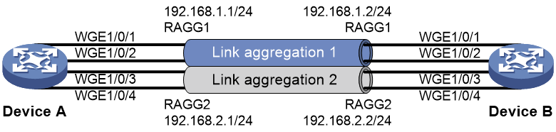
Procedure
1. Configure Device A:
# Create Layer 3 aggregate interface Route-Aggregation 1.
<DeviceA> system-view
[DeviceA] interface route-aggregation 1
# Configure Layer 3 aggregation group 1 to load share packets based on source IP addresses.
[DeviceA-Route-Aggregation1] link-aggregation load-sharing mode source-ip
# Configure an IP address and subnet mask for Layer 3 aggregate interface Route-Aggregation 1.
[DeviceA-Route-Aggregation1] ip address 192.168.1.1 24
[DeviceA-Route-Aggregation1] quit
# Assign Layer 3 Ethernet interfaces Twenty-FiveGigE 1/0/1 and Twenty-FiveGigE 1/0/2 to aggregation group 1.
[DeviceA] interface twenty-fivegige 1/0/1
[DeviceA-Twenty-FiveGigE1/0/1] port link-aggregation group 1
[DeviceA-Twenty-FiveGigE1/0/1] quit
[DeviceA] interface twenty-fivegige 1/0/2
[DeviceA-Twenty-FiveGigE1/0/2] port link-aggregation group 1
[DeviceA-Twenty-FiveGigE1/0/2] quit
# Create Layer 3 aggregate interface Route-Aggregation 2.
[DeviceA] interface route-aggregation 2
# Configure Layer 3 aggregation group 2 to load share packets based on destination IP addresses.
[DeviceA-Route-Aggregation2] link-aggregation load-sharing mode destination-ip
# Configure an IP address and subnet mask for Layer 3 aggregate interface Route-Aggregation 2.
[DeviceA-Route-Aggregation2] ip address 192.168.2.1 24
[DeviceA-Route-Aggregation2] quit
# Assign Layer 3 Ethernet interfaces Twenty-FiveGigE 1/0/3 and Twenty-FiveGigE 1/0/4 to aggregation group 2.
[DeviceA] interface twenty-fivegige 1/0/3
[DeviceA-Twenty-FiveGigE1/0/3] port link-aggregation group 2
[DeviceA-Twenty-FiveGigE1/0/3] quit
[DeviceA] interface twenty-fivegige 1/0/4
[DeviceA-Twenty-FiveGigE1/0/4] port link-aggregation group 2
[DeviceA-Twenty-FiveGigE1/0/4] quit
2. Configure Device B in the same way Device A is configured. (Details not shown.)
Verifying the configuration
# Display detailed information about all aggregation groups on Device A.
[DeviceA] display link-aggregation verbose
Loadsharing Type: Shar -- Loadsharing, NonS -- Non-Loadsharing
Port Status: S -- Selected, U -- Unselected, I -- Individual
Port: A -- Auto port, M -- Management port, R -- Reference port
Flags: A -- LACP_Activity, B -- LACP_Timeout, C -- Aggregation,
D -- Synchronization, E -- Collecting, F -- Distributing,
G -- Defaulted, H -- Expired
Aggregate Interface: Route-Aggregation1
Aggregation Mode: Static
Loadsharing Type: Shar
Management VLANs: None
Port Status Priority Oper-Key
WGE1/0/1(R) S 32768 1
WGE1/0/2 S 32768 1
Aggregate Interface: Route-Aggregation2
Aggregation Mode: Static
Loadsharing Type: Shar
Management VLANs: None
Port Status Priority Oper-Key
WGE1/0/3(R) S 32768 2
WGE1/0/4 S 32768 2
The output shows that:
· Link aggregation groups 1 and 2 are both load-shared Layer 3 static aggregation groups.
· Each aggregation group contains two Selected ports.
# Display all the group-specific load sharing modes on Device A.
[DeviceA] display link-aggregation load-sharing mode interface
The dynamic load sharing mode takes effect if it exists.
Route-Aggregation1 load-sharing mode:
Dynamic:
N/A
Static:
source-ip address
The dynamic load sharing mode takes effect if it exists.
Route-Aggregation2 load-sharing mode:
Dynamic:
N/A
Static:
destination-ip address
The output shows that:
· Link aggregation group 1 distributes packets based on source IP addresses.
· Link aggregation group 2 distributes packets based on destination IP addresses.
Example: Configuring S-MLAG
Network configuration
Device B, Device C, and Device D are standalone devices. As shown in Figure 15, configure Device B, Device C, and Device D as S-MLAG devices to establish a multidevice aggregate link with Device A.
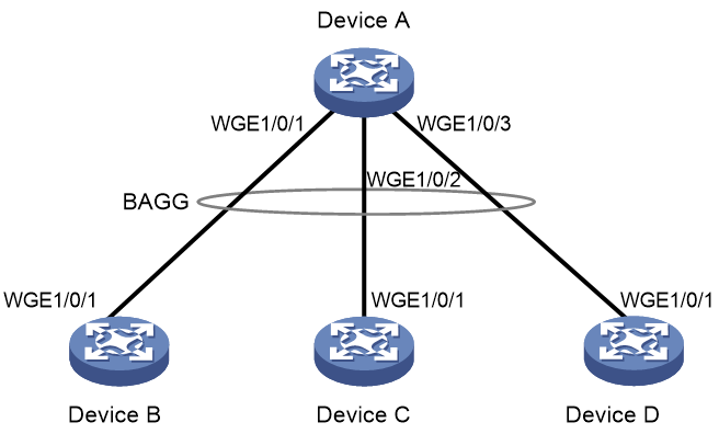
Procedure
1. Configure Device A:
# Create Layer 2 aggregate interface Bridge-Aggregation 10, and set the link aggregation mode to dynamic.
<DeviceA> system-view
[DeviceA] interface bridge-aggregation 10
[DeviceA-Bridge-Aggregation10] link-aggregation mode dynamic
[DeviceA-Bridge-Aggregation10] quit
# Assign Twenty-FiveGigE 1/0/1 through Twenty-FiveGigE 1/0/3 to aggregation group 10.
[DeviceA] interface twenty-fivegige 1/0/1
[DeviceA-Twenty-FiveGigE1/0/1] port link-aggregation group 10
[DeviceA-Twenty-FiveGigE1/0/1] quit
[DeviceA] interface twenty-fivegige 1/0/2
[DeviceA-Twenty-FiveGigE1/0/2] port link-aggregation group 10
[DeviceA-Twenty-FiveGigE1/0/2] quit
[DeviceA] interface twenty-fivegige 1/0/3
[DeviceA-Twenty-FiveGigE1/0/3] port link-aggregation group 10
[DeviceA-Twenty-FiveGigE1/0/3] quit
2. Configure Device B:
# Set the LACP system MAC address to 0001-0001-0001.
<DeviceB> system-view
[DeviceB] lacp system-mac 1-1-1
# Set the LACP system priority to 123.
[DeviceB] lacp system-priority 123
# Set the LACP system number to 1.
[DeviceB] lacp system-number 1
# Create Layer 2 aggregate interface Bridge-Aggregation 2, and set the link aggregation mode to dynamic.
[DeviceB] interface bridge-aggregation 2
[DeviceB-Bridge-Aggregation2] link-aggregation mode dynamic
# Assign Bridge-Aggregation 2 to S-MLAG group 100.
[DeviceB-Bridge-Aggregation2] port s-mlag group 100
# Assign Twenty-FiveGigE 1/0/1 to aggregation group 2.
[DeviceB] interface twenty-fivegige 1/0/1
[DeviceB-Twenty-FiveGigE1/0/1] port link-aggregation group 2
[DeviceB-Twenty-FiveGigE1/0/1] quit
3. Configure Device C:
# Set the LACP system MAC address to 0001-0001-0001.
<DeviceC> system-view
[DeviceC] lacp system-mac 1-1-1
# Set the LACP system priority to 123.
[DeviceC] lacp system-priority 123
# Set the LACP system number to 2.
[DeviceC] lacp system-number 2
# Create Layer 2 aggregate interface Bridge-Aggregation 3, and set the link aggregation mode to dynamic.
[DeviceC] interface bridge-aggregation 3
[DeviceC-Bridge-Aggregation3] link-aggregation mode dynamic
# Assign Bridge-Aggregation 3 to S-MLAG group 100.
[DeviceC-Bridge-Aggregation3] port s-mlag group 100
# Assign Twenty-FiveGigE 1/0/1 to aggregation group 3.
[DeviceC] interface twenty-fivegige 1/0/1
[DeviceC-Twenty-FiveGigE1/0/1] port link-aggregation group 3
[DeviceC-Twenty-FiveGigE1/0/1] quit
4. Configure Device D:
# Set the LACP system MAC address to 0001-0001-0001.
<DeviceD> system-view
[DeviceD] lacp system-mac 1-1-1
# Set the LACP system priority to 123.
[DeviceD] lacp system-priority 123
# Set the LACP system number to 3.
[DeviceD] lacp system-number 3
# Create Layer 2 aggregate interface Bridge-Aggregation 4, and set the link aggregation mode to dynamic.
[DeviceD] interface bridge-aggregation 4
[DeviceD-Bridge-Aggregation4] link-aggregation mode dynamic
# Assign Bridge-Aggregation 4 to S-MLAG group 100.
[DeviceD-Bridge-Aggregation4] port s-mlag group 100
# Assign Twenty-FiveGigE 1/0/1 to aggregation group 4.
[DeviceD] interface twenty-fivegige 1/0/1
[DeviceD-Twenty-FiveGigE1/0/1] port link-aggregation group 4
[DeviceD-Twenty-FiveGigE1/0/1] quit
Verifying the configuration
# Verify that Twenty-FiveGigE 1/0/1 through Twenty-FiveGigE 1/0/3 on Device A are Selected ports.
[DeviceA] display link-aggregation verbose
Loadsharing Type: Shar -- Loadsharing, NonS -- Non-Loadsharing
Port Status: S -- Selected, U -- Unselected, I -- Individual
Port: A -- Auto port, M -- Management port, R -- Reference port
Flags: A -- LACP_Activity, B -- LACP_Timeout, C -- Aggregation,
D -- Synchronization, E -- Collecting, F -- Distributing,
G -- Defaulted, H -- Expired
Aggregate Interface: Bridge-Aggregation10
Creation Mode: Manual
Aggregation Mode: Dynamic
Loadsharing Type: Shar
Management VLANs: None
System ID: 0x8000, 40fa-264f-0100
Local:
Port Status Priority Index Oper-Key Flag
WGE1/0/1(R) S 32768 1 1 {ACDEF}
WGE1/0/2 S 32768 2 1 {ACDEF}
WGE1/0/3 S 32768 3 1 {ACDEF}
Remote:
Actor Priority Index Oper-Key SystemID Flag
WGE1/0/1 32768 16385 50100 0x7b , 0001-0001-0001 {ACDEF}
WGE1/0/2 32768 32769 50100 0x7b , 0001-0001-0001 {ACDEF}
WGE1/0/3 32768 49153 50100 0x7b , 0001-0001-0001 {ACDEF}