- Table of Contents
- Related Documents
-
| Title | Size | Download |
|---|---|---|
| 02-Appendix | 547.30 KB |
Contents
Appendix A About the BX1010E switch module
Switch module and mezzanine network adapter connections
Switch module and mezzanine network adapter port connections
Mezzanine network adapters compatible with the switch module
Transceiver module and cables available for the switch module
Appendix A About the BX1010E switch module
Hardware figures in this document are for illustration only.
Screenshots in this document are taken on a specific software version and are for illustration only.
Switch module is a type of interconnect module and is also called interconnect module in this document.
Introduction
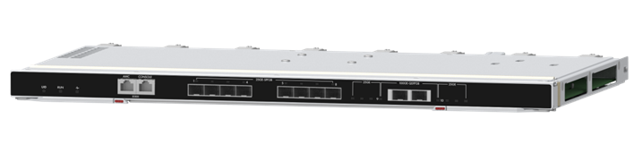
H3C UniServer BX1010E switch module, as an Ethernet switching control unit inside the enclosure, provides data switching for the blade servers. It also provides external data ports to connect the blade servers to the external network.
Figure 1 BX1010E switch module
High availability
The switch modules can be configured in redundancy. The enclosure supports a maximum of six switch modules. See Figure 2 for the slots for the switch modules. The six switch modules form three module pairs with internal ports inter-connected: Slots 1 and 4 pair, slots 2 and 5 pair, and slots 3 and 6 pair. Each pair can be used as a switching plane. You can configure the switch modules in a pair to operate in active/standby mode as needed.
Figure 2 Installation position

Technical specifications
Table 1 Technical specifications
|
Item |
Specification |
|
|
Dimensions (H × W × D) |
27 × 491.6 × 296.5 mm (1.06 × 19.35 × 11.67 in) |
|
|
Weight |
3.48 kg (7.67 lb) |
|
|
Max. power consumption |
80 W |
|
|
Environment |
Temperature |
· Operating: 5°C to 45°C (41°F to 113°F) · Storage: –40°C to +70°C (–40°F to +158°F) |
|
· Operating: 8% to 90%, noncondensing · Storage: 5% to 95%, noncondensing |
||
|
· Operating: –60 m to +5000 m (–196.85 ft to +16404.20 ft) The allowed maximum temperature decreases by 0.33 °C (32.59 °F) as the altitude increases by 100 m (328.08 ft) from 900 m (2952.76 ft). Storage: –60 m to +5000 m (–196.85 ft to +16404.20 ft) |
||
Ports
Port numbering
The ports on the switch module are numbered in the format of A/B/C:
· A—IRF member device ID. By default, switch modules are not set up in an IRF fabric. The default value of A is 1.
Devices with the same member ID cannot set up an IRF fabric. To change the IRF member ID for a device, execute the irf member renumber command.
· B—Differentiates between internal and external ports. 0 represents an internal port and 1 represents an external port.
· C—Number of the port on the switch module.
A breakout interface split from a port is numbered in the format of A/B/C:D. D represents the breakout interface number, which is in the range of 1 to 4.
External ports
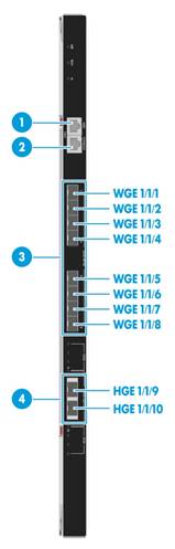
Figure 3 External ports
|
(1) AMC serial port |
(2) SYS serial port (console port) |
|
(3) 25-GE fiber ports |
(4) 100-GE fiber ports |
Table 2 External port description
|
Number |
Port name |
Port type |
Quantity |
Description |
|
1 |
AMC serial port |
RJ-45 |
1 |
You can access the AMC CLI of the switch module from the port. The baud rate is 115200 bps. It can be used only by technical engineers to upgrade the AMC firmware version. |
|
2 |
SYS serial port (console port) |
RJ-45 |
1 |
You can access the CLI of the switch module from the port for local management, debugging, and maintenance. The baud rate is 9600 bps. |
|
3 |
25-GE fiber port |
SFP28 |
8 |
N/A |
|
4 |
100-GE fiber port |
QSFP28 |
4 |
A 100-GE fiber port can be used as follows: · A single 100-GE port. · Split into 4 × 25-GE ports. After it is split, the port can only use a 100G transceiver module or cable that supports splitting for connection. · Split into 4 × 10GE ports. After it is split, the port can only use a 40G transceiver module or cable that support splitting for connection. |
|
· For the transceiver module and cables available for the switch module and their specifications, see "Transceiver module and cables available for the switch module." · For information about splitting a 100-GE fiber port and combining breakout interfaces, see "Splitting a 100-GE interface and combining breakout interfaces into a 100-GE interface." |
||||
Internal ports
Table 3 Internal port description
|
Port name |
Quantity |
Description |
|
25-GE port |
20 |
· 16 of the 25-GE internal ports are used to connect the blade servers. The 16 ports are numbered WGE 1/0/1 to WGE 1/0/16. · 4 of the 25-GE internal ports are used to connect the pair switch module through the midplane. The 4 ports are numbered WGE 1/0/17 to WGE1/0/20. (The six switch modules form three module pairs with internal ports inter-connected: Slots 1 and 4 pair, slots 2 and 5 pair, and slots 3 and 6 pair.) As a best practice, use these ports as IRF physical ports. |
|
10-GE port |
2 |
The two 10-GE internal ports are used to connect the AE module. Only switch modules in slot 1 and 4 can connect the AE module. The two ports are numbered XGE1/0/21 and XGE1/0/22. |
LEDs and buttons
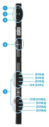
Figure 4 LED and buttons
|
(1) UID LED |
(2) RUN LED |
|
(3) Health LED |
(4) 25-GE fiber port LED |
|
(5) 100-GE fiber port/breakout interface LEDs |
|
|
· The eight 25-GE fiber port LEDs are the same in appearance. One of these LEDs is marked in the figure for illustration. · Each of the two 100-GE fiber ports has four LEDs. ¡ If a 100-GE fiber port is used as a single port, the LED nearest to it indicates its status. The other three LEDs are off. ¡ If a 100-GE fiber port is split into four interfaces, each of the four LEDs indicates the operating status of a breakout interface. The matching relations between the LEDs and breakout interfaces are as shown in the figure. |
|
Table 4 Description for LEDs and buttons
|
Number |
LED name |
Status |
|
|
1 |
UID LED (UID) |
· Steady blue—The UID LED is activated. The UID LED can be activated from the OM. · Flashing blue (1 Hz)—The module is being managed from SOL or firmware is being upgraded from the OM. · Off—The UID LED is not activated. |
|
|
2 |
RUN LED (RUN) |
· Steady green/off—A system failure has occurred. · Flashing green (4 Hz)—The system is being loaded. · Flashing green (1 Hz)—The system is operating correctly. |
|
|
3 |
Health LED ( |
· Steady green—The switch module is operating correctly. · Flashing red (1 Hz)—An alarm is present on the switch module. · Off—No power is present on the switch module, or the switch module is not installed securely in the slot. |
|
|
4 |
25-GE fiber port LED |
· Steady green—A link is present on the port and the port rate is 25 Gbps, but no data is being transmitted or received on the port. · Flashing green—A link is present on the port and the port rate is 25 Gbps, and data is being transmitted or received on the port. · Steady yellow—A link is present on the port and the port rate is 10 Gbps, but no data is being transmitted or received on the port.. · Flashing yellow—A link is present on the port and the port rate is 10 Gbps, and data is being transmitted or received on the port. · Off—No link is present on the port. |
|
|
5 |
100-GE fiber port/breakout interface LED |
Not spitted |
The LED nearest to the port indicates the port status. The other three LEDs are off. · Steady green—A link is present on the port and the port rate is 100 Gbps, but no data is being transmitted or received on the port. · Flashing green—A link is present on the port and the port rate is 100 Gbps, and data is being transmitted or received on the port. · Steady yellow—A link is present on the port and the port rate is 40 Gbps, but no data is being transmitted or received on the port. · Flashing yellow—A link is present on the port and the port rate is 40 Gbps, and data is being transmitted or received on the port. · Off—No link is present on the port. |
|
Split into 4 × 25-GE ports |
Each of the four LEDs indicates the operating status of a breakout interface: · Steady green—A link is present on the breakout interface and the interface rate is 25 Gbps, but no data is being transmitted or received on the interface. · Flashing green—A link is present on the breakout interface and the interface rate is 25 Gbps, and data is being transmitted or received on the interface. · Off—No link is present on the interface |
||
|
Split into 4 × 10GE ports |
Each of the four LEDs indicates the operating status of a breakout interface: · Steady green—A link is present on the breakout interface and the interface rate is 10 Gbps, but no data is being transmitted or received on the interface. · Flashing green—A link is present on the breakout interface and the interface rate is 10 Gbps, and data is being transmitted or received on the interface. · Off—No link is present on the interface |
||
|
· For the location and appearance of the LEDs, see Figure 4. · For information about splitting a 100-GE fiber port and combining breakout interfaces, see "Splitting a 100-GE interface and combining breakout interfaces into a 100-GE interface." |
|||
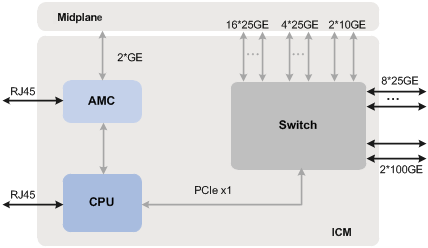
Logical architecture
As shown in Figure 5, the switch module contains three logical units:
· CPU unit—As the control and management core of the switch module, it is responsible for module management, system configuration, and special packet processing.
· AMC unit—As the auxiliary management unit of the switch module, it is responsible for data collection and report, power up/down control of the module, and system monitoring.
· Switch unit—As the data processing core of the switch module, it is responsible for internal and external data forwarding and report of unrecognized packets.
Installation guidelines
Follow these guidelines when you install switch modules:
· As shown in Figure 6, you can install a maximum of six switch modules in the enclosure.
· The installation positions of switch modules and mezzanine network adapters must allow their internal connections.
· The six switch modules form three pairs with internal ports inter-connected: Slots 1 and 4 pair, slots 2 and 5 pair, and slots 3 and 6 pair. Each pair can be used as a switching plane, and the switch modules in each pair operate in active/standby mode.
· The switch module can be hot swapped.
Figure 6 Switch module installation slots
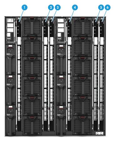
|
(1) ICM1 slot |
(2) ICM2 slot |
(3) ICM3 slot |
|
(4) ICM4 slot |
(5) ICM5 slot |
(6) ICM6 slot |
Internal connections
Switch module and mezzanine network adapter connections
The installation positions of switch modules and mezzanine network adapters must allow their internal connections as described in Table 5.
Table 5 Switch module and mezzanine network adapters connections
|
Blade server model |
Max number of mezzanine network adapters on the server |
Internal connection diagram between switch modules and mezzanine network adapters |
|
|
H3C UniServer B5700 G5 |
3 |
The connection diagrams are logical diagrams, presenting the connection relations between the mezzanine network adapter slots and switch module slots. For the specific locations of the mezzanine network adapter slots and switch module slots, see the marks on the modules. |
|
|
H3C UniServer B5700 G3 |
3 |
||
|
H3C UniServer B7800 G3 |
6 |
||
|
H3C UniServer B5800 G3 |
3 |
||
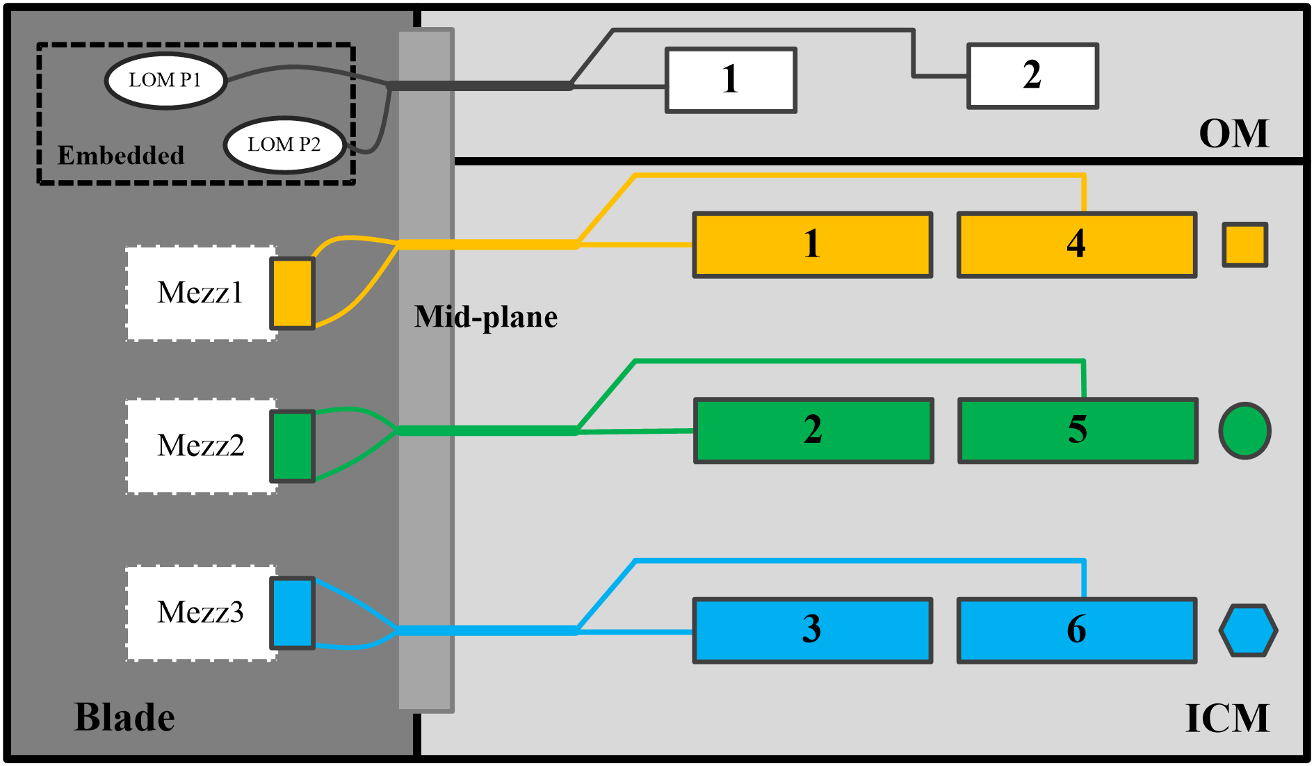
Switch module and mezzanine network adapter internal connections (method 1)
As shown in Figure 7, switch modules and mezzanine network adapters are connected as follows:
· Network adapters embedded in the system board connected to the active and standby OMs.
· Mezzanine network adapter 1 connected to switch modules in slots 1 and 4.
· Mezzanine network adapter 2 connected to switch modules in slots 2 and 5.
· Mezzanine network adapter 3 connected to switch modules in slots 3 and 6.
Figure 7 Switch module and mezzanine network adapter internal connections (method 1)
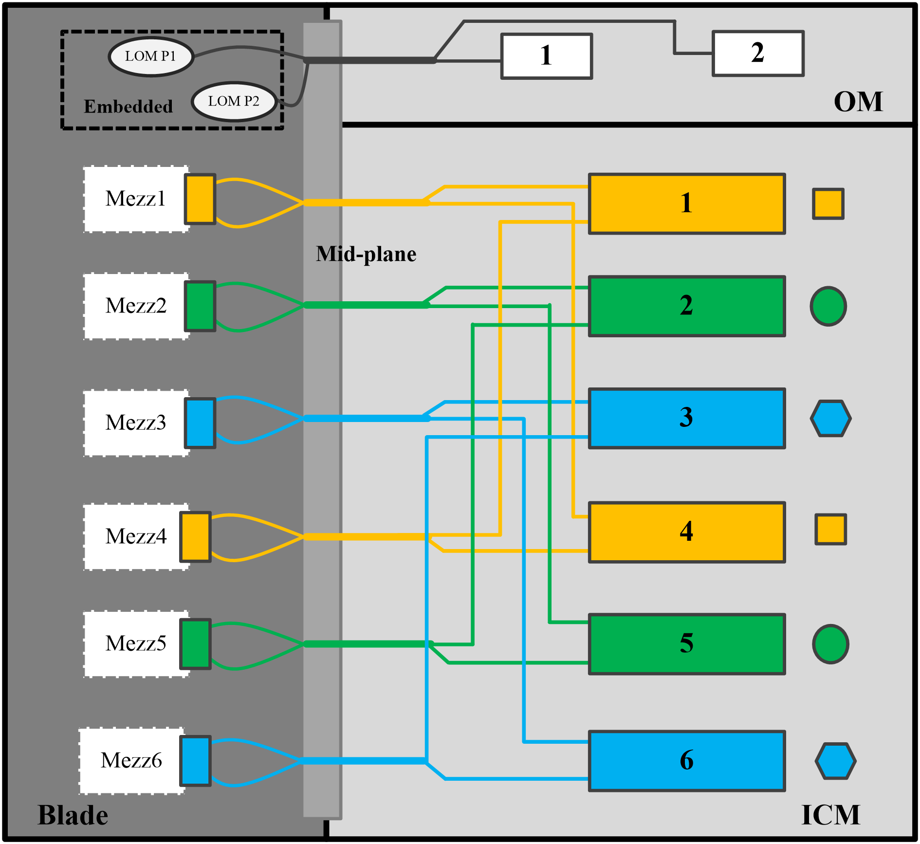
Switch module and mezzanine network adapter internal connections (method 2)
As shown in Figure 8, switch modules and mezzanine network adapters are collected as follows:
· Network adapter embedded in the system board connected to the active and standby OMs.
· Mezzanine network adapters 1 and 4 connected to switch modules in slots 1 and 4.
· Mezzanine network adapters 2 and 5 connected to switch modules in slots 2 and 5.
· Mezzanine network adapters 3 and 6 connected to switch modules in slots 3 and 6.
Figure 8 Switch module and mezzanine network adapter internal connections (method 2)
Switch module and mezzanine network adapter port connections
Before configuring mezzanine network adapters on the blade server, identify the connections between the mezzanine network adapter ports and switch modules.
Hardware compatibility
Mezzanine network adapters compatible with the switch module
Table 6 describes the mezzanine network adapters compatible with the BX1010E switch modules.
Table 6 Mezzanine network adapters compatible with the BX1010E switch modules
|
Mezzanine network adapter model |
Port quantity |
Description |
|
NIC-ETH561i-Mb-4*10G |
4 |
4-port 10Gb Ethernet mezzanine network adapter |
|
NIC-ETH522i-Mb-2*10G |
2 |
4-port 10Gb converged mezzanine network adapter |
|
NIC-ETH521i-Mb-4*10G |
4 |
2-port 25Gb converged mezzanine network adapter |
|
NIC-ETH640i-Mb-2*25G |
2 |
2-port 25Gb Ethernet mezzanine network adapter |
|
NIC-ETH681i-Mb-2*25G |
2 |
2-port 25Gb Ethernet mezzanine network adapter |
|
NIC-ETH682i-Mb-2*25G |
2 |
2-port 25Gb converged mezzanine network adapter |
Transceiver module and cables available for the switch module
The following tables describe the transceiver module and cables available for the switch module.
Table 7 Transceiver module and cables available for the switch module (1)
|
Transceiver module/cable model |
Type |
Central wavelength |
Max transmission distance |
Remarks |
|
QSFP-40G-D-AOC-20M |
QSFP+ |
N/A |
20 m (65.62 ft) |
QSFP+ AOC cable |
|
QSFP-40G-D-AOC-20M |
QSFP+ |
N/A |
20 m (65.62 ft) |
QSFP+ AOC cable |
Table 8 Transceiver module and cables available for the switch module (2)
|
Transceiver module/cable model |
Type |
Central wavelength |
Max transmission distance |
Remarks |
|
SFP-FC-8G-SW-MM850-CM |
SFP |
850 nm |
· 150 m (492.13 ft) (8G) · 380 m (1246.72 ft) (4G) · 500 m (1640.42 ft) (2G) |
8G/4G/2G FC fiber port transceiver module |
|
SFP-FC-8G-SW-MM850 |
SFP |
850 nm |
· 150 m (492.13 ft) (8G) · 380 m (1246.72 ft) (4G) · 500 m (1640.42 ft) (2G) |
8G/4G/2G FC fiber port transceiver module |
|
SFP-FC-16G-SW-MM850-CM |
SFP |
850 nm |
· 100 m (328.08 ft) (16G) · 150 m (492.13 ft) (8G) · 380 m (1246.72 ft) (4G) |
16G/8G/4G FC fiber port transceiver module |
|
SFP-FC-16G-SW-MM850 |
SFP |
850 nm |
· 100 m (328.08 ft) (16G) · 150 m (492.13 ft) (8G) · 380 m (1246.72 ft) (4G) |
16G/8G/4G FC fiber port transceiver module |
|
SFP-FC-16G-LW-SM1310-CM |
SFP |
1310 nm |
10 km (6.21 miles) |
16G/8G/4G FC fiber port transceiver module |
|
SFP-FC-16G-LW-SM1310 |
SFP |
1310 nm |
10 km (6.21 miles) |
16G/8G/4G FC fiber port transceiver module |
Table 9 Transceiver module and cables available for the switch module (3)
|
Transceiver module/cable model |
Central wavelength |
Connector |
Fiber/cable specifications |
Max transmission distance |
|
SFP+ transceiver modules |
||||
|
SFP-XG-SX-MM850-A1 |
850 nm |
LC |
50/125 µm, MMF |
300 m (984.25 ft) |
|
62.5/125 µm, MMF |
33 m (108.27 ft) |
|||
|
SFP-XG-SX-MM850-A |
50/125 µm, MMF |
300 m (984.25 ft) |
||
|
62.5/125 µm, MMF |
33 m (108.27 ft) |
|||
|
SFP-XG-SX-MM850-E1 |
50/125 µm, MMF |
300 m (984.25 ft) |
||
|
62.5/125 µm, MMF |
33 m (108.27 ft) |
|||
|
SFP-XG-SX-MM850-E |
50/125 µm, MMF |
300 m (984.25 ft) |
||
|
62.5/125 µm, MMF |
33 m (108.27 ft) |
|||
|
SFP-XG-LX-SM1310-CM |
1310 nm |
9/125 µm, SMF |
10 km (6.21 miles) |
|
|
SFP-XG-LX-SM1310-E |
9/125 µm, SMF |
10 km (6.21 miles) |
||
|
SFP28 transceiver modules |
||||
|
SFP-25G-SR-MM850-1 |
850 nm |
LC |
50/125 µm, MMF |
100 m (328.08 ft) |
|
SFP-25G-SR-MM850-1-X |
50/125 µm, MMF |
100 m (328.08 ft) |
||
|
QSFP+ transceiver modules |
||||
|
QSFP-40G-SR4-MM850-CM |
850 nm |
MPO |
50/125 µm, MMF |
150 m (492.13 ft) |
|
QSFP-40G-SR4-MM850 |
50/125 µm, MMF |
150 m (492.13 ft) |
||
|
QSFP-40G-CSR4-MM850-CM |
50/125 µm, MMF |
400 m (1312.34 ft) |
||
|
QSFP-40G-SR4-MM850 |
50/125 µm, MMF |
400 m (1312.34 ft) |
||
|
QSFP28 transceiver modules |
||||
|
QSFP-100G-SR4-MM850-CM |
850 nm |
MPO |
50/125 µm, MMF |
100 m (328.08 ft) |
|
QSFP-100G-SR4-MM850 |
50/125 µm, MMF |
100 m (328.08 ft) |
||
|
SFP+ copper cables |
||||
|
SFP-XG-CAB-3M-CM |
N/A |
N/A |
SFP+ copper cable |
3 m (9.84 ft) |
|
LSWM3STK |
3 m (9.84 ft) |
|||
|
SFP-XG-CAB-5M-CM |
5 m (16.40 ft) |
|||
|
LSTM1STK |
5 m (16.40 ft) |
|||
|
SFP28 copper cables |
||||
|
SFP-25G-D-CAB-3M |
N/A |
N/A |
SFP28 copper cable |
3 m (9.84 ft) |
|
SFP-25G-D-CAB-3M-CM |
3 m (9.84 ft) |
|||
|
QSFP+ copper cables |
||||
|
QSFP-40G-3M-CM |
N/A |
N/A |
QSFP+ copper cable |
3 m (9.84 ft) |
|
QSFP-40G-5M-CM |
5 m (16.40 ft) |
|||
|
QSFP+ fiber cables |
||||
|
QSFP-40G-D-AOC-7M-CM |
N/A |
N/A |
QSFP+ fiber cable |
7 m (22.97 ft) |
|
QSFP-40G-D-AOC-7M |
7 m (22.97 ft) |
|||
|
QSFP-40G-D-AOC-10M-CM |
10 m (32.81 ft) |
|||
|
QSFP-40G-D-AOC-10M |
10 m (32.81 ft) |
|||
|
QSFP-40G-D-AOC-20M-CM |
20 m (65.62 ft) |
|||
|
QSFP-40G-D-AOC-20M |
20 m (65.62 ft) |
|||
|
QSFP28 copper cables |
||||
|
QSFP-100G-D-CAB-3M |
N/A |
N/A |
QSFP28 copper cable |
3 m (9.84 ft) |
|
QSFP-100G-D-CAB-3M-CM |
3 m (9.84 ft) |
|||
|
QSFP28 to 4 × SFP28 copper cables |
||||
|
QSFP-100G-4SFP-25G-CAB-3M-CM |
N/A |
N/A |
QSFP28 to 4*SFP28 copper cable |
3 m (9.84 ft) |
|
QSFP-100G-4SFP-25G-CAB-3M |
3 m (9.84 ft) |
|||
|
QSFP-100G-4SFP-25G-CAB-5M-CM |
5 m (16.40 ft) |
|||
|
QSFP-100G-4SFP-25G-CAB-5M |
5 m (16.40 ft) |
|||
|
· You can use a QSFP-100G-4SFP-25G-CAB-3M-CM, QSFP-100G-4SFP-25G-CAB-3M, QSFP-100G-4SFP-25G-CAB-5M-CM, or QSFP-100G-4SFP-25G-CAB-5M cable to connect a 100G QSFP28 port to four 25G SFP28 ports when the 100G port is split into four 25-GE ports. · You can use a QSFP-40G-SR4-MM850-CM, QSFP-40G-SR4-MM850, QSFP-40G-CSR4-MM850-CM, or QSFP-40G-SR4-MM850 transceiver module to connect one 40G QSFP+ port to four 10G SFP+ ports. The QSFP+ transceiver module and SFP+ transceiver modules at the two ends must be the same in central wavelength and fiber type. |
||||
|
|
IMPORTANT: · As a best practice, use H3C transceiver modules and cables for the switch module. For the specifications of H3C transceiver modules and cables, see H3C Transceiver Modules User Guide. · H3C transceiver modules and cables are subject to change over time. For the most up-to-date list of H3C transceiver modules and cables, contact H3C Support or marketing staff. · Always wear an ESD wrist strap when installing transceiver modules and cables. For the installation method and precautions, see H3C Transceiver Modules and Network Cables Installation Guide. |
Appendix B Technical support
· Log and sensor information:
· Product serial number.
· Product model and name.
· Snapshots of error messages and descriptions.
· Hardware change history, including installation, replacement, insertion, and removal of hardware.
Appendix C Product recycling
New H3C Technologies Co., Ltd. provides product recycling services for its customers to ensure that hardware at the end of its life is recycled. Vendors with product recycling qualification are contracted to New H3C to process the recycled hardware in an environmentally responsible way.
For product recycling services, contact New H3C at
· Tel: 400-810-0504
· E-mail: [email protected]
· Website: http://www.h3c.com
Appendix D Glossary
|
Description |
|
|
Hot swapping |
A module that supports hot swapping (a hot-swappable module) can be installed or removed while the server is running without affecting the system operation. |
|
Redundancy |
A mechanism that ensures high availability and business continuity by providing backup modules. In redundancy mode, a backup or standby module takes over when the primary module fails. |
Appendix E Acronyms
|
Acronym |
Full name |
|
A |
|
|
AE |
App Engine |
|
AMC |
Auxiliary Management Controller |
|
C |
|
|
CLI |
Command-line interface |
|
F |
|
|
FC |
Fiber Channel |
|
FCoE |
Fibre Channel over Ethernet |
|
FCF |
FCoE Forwarder |
|
I |
|
|
ICM |
Interconnect module |
|
IRF |
Intelligent Resilient Framework |
|
M |
|
|
Mezz |
Mezzanine |
|
N |
|
|
NPV |
N_Port Virtualization |
|
O |
|
|
OM |
Onboard Manager |
|
S |
|
|
SOL |
Serial Over LAN |
|
SSH |
Secure Shell |
|
U |
|
|
UID |
Unit identification |
