- Table of Contents
- Related Documents
-
| Title | Size | Download |
|---|---|---|
| 01-Text | 1.01 MB |
Powering on and powering off the module
Powering off the switch module
Accessing the switch module from the SYS serial port (console port)
Accessing the switch module through SOL serial port redirection
Configuring a management IP address for the switch module
Obtaining and planning related data
Configuring a management IP address from the OM Web interface
Configuring a management IP address from the OM CLI
Configuring a management IP address from the switch module CLI
Splitting a 100-GE interface and combining breakout interfaces into a 100-GE interface
Splitting a 100-GE interface into four 25-GE interfaces
Splitting a 100-GE interface into four 10-GE interfaces
Combining breakout interfaces into a 100-GE interface
Configuring switch module services
Safety information
To avoid bodily injury or damage to the module, read the following information carefully before you operate the module. In practice, safety information includes but is not limited to what are mentioned in this document.
General operating safety
To avoid bodily injury or damage to the module, follow these guidelines when you operate the module:
· Only H3C authorized or professional engineers are allowed to install, service, repair, operate, or upgrade the module.
· Place the module on a clean, stable table or floor for servicing.
· Keep the module clean and dust-free, and do not place the module in a wet environment or let liquid flow into the module.
· When using tools for servicing, be sure to follow the operation instructions.
· Before powering on the module, make sure the server is grounded reliably.
· Make sure that you move or place the module evenly and slowly.
· To avoid being burnt, allow the module and its internal modules to cool before touching them.
· For adequate heat dissipation of the server, install a filler panel in the slot if the module is not installed.
Electrical safety
To avoid bodily injury or damage to the module, follow these guidelines:
· Verify whether the operation area has potential risks carefully, such as an ungrounded chassis, unreliable grounding, or wet floor.
· Do not work alone when you service the module with power present.
· To avoid electric shocks, do not touch the power supply directly or indirectly through conductive objects.
Laser safety
|
|
WARNING! Disconnected optical fibers or transceiver modules might emit invisible laser light. Do not stare into beams or view directly with optical instruments when the module is operating |
ESD prevention
Preventing electrostatic discharge
To prevent electrostatic damage, follow these guidelines:
· Transport or store the module in an antistatic bag.
· Place the module on a grounded surface before removing it from its antistatic bag.
· Avoid touching pins, leads, or circuitry.
· You must take ESD preventions before touching the electrostatic-sensitive components.
Grounding methods to prevent electrostatic discharge
The following are grounding methods that you can use to prevent electrostatic discharge:
· Wear an ESD wrist strap and make sure it makes good skin contact and is reliably grounded.
· Take adequate personal grounding measures, including wearing antistatic clothing and static dissipative shoes.
· Use conductive field service tools.
· Use a portable field service kit with a folding static-dissipating work mat.
Replacing the switch module
Hardware figures in this document are for illustration only.
Screenshots in this document are taken on a specific software version and are for illustration only.
Switch module is a type of interconnect module and is also called interconnect module in this document.
Tools
Table 1 lists the tools that you might use when replacing the switch module.
|
Picture |
Name |
Description |
|
|
Diagonal pliers |
Cuts insulation tubes and cable ties. |
|
|
Multimeter |
Measures resistance and voltage. |
|
|
ESD wrist strap |
Prevents ESD when you install, remove, or service the module. |
|
|
Antistatic gloves |
|
|
|
Antistatic clothing |
|
|
|
Ladder |
Supports operations at height. |
|
|
Interface cable (such as an Ethernet cable or optical fiber) |
Connects the module to an external network. |
|
|
Terminal (for example, a PC) |
Used for accessing the module. |


Preparing for replacement
Before replacing a switch module, make the following preparations.
· Take the following ESD prevention measures:
¡ Wear ESD clothing.
¡ Wear an ESD wrist strap and make sure it is grounded reliably.
¡ Remove any conductive objects (such as jewelry and watches).
· Backup the switch module configuration.
· Examine the slot and connector for damages. Make sure the pins are not damaged (bent for example) and do not contain any foreign objects.
· Be clear about the switch module installation guidelines.
¡ Install a maximum of switch modules for the server.
¡ The installation positions of switch modules and mezzanine network adapters must allow their internal connections.
¡ The six switch modules form three pairs with internal ports inter-connected: Slots 1 and 4 pair, slots 2 and 5 pair, and slots 3 and 6 pair. Each pair can be used as a switching plane, and the switch modules in each pair operate in active/standby mode.
¡ The switch module can be hot swapped.
Replacement procedure
1. Press the release button on the switch module to fully open the ejector levers and then pull the module out from the chassis.
2. Place the switch module into an antistatic bag.
3. Take the new switch module from the antistatic bag.
4. Press the release button on the new switch module to fully open the ejector levers
5. Orient the switch module with the "UP" word facing upward, insert it into the chassis slowly, and then close the ejector levers.
Powering on and powering off the module
Powering on the module
Power-on methods
The switch module supports the following power-on methods.
Table 2 Switch module power-on methods
|
Power-on method |
Application scenario |
|
Together with the server |
· The switch module is installed on the server before the server is powered on. · The switch is installed on the server after the server is powered on. |
|
From the OM Web interface |
The switch module is installed on an operating server and the module is powered off (the heath LED on the module is off). |
|
From the OM CLI |
Procedure
When power is present on the switch module, its health LED is steady green. For the health LED location on the module, see "LEDs and buttons."
Powering on the switch module together with the server
· If the switch module has been installed on the server before the server is powered on, it will power on automatically when the chassis is powered on. You are not required to perform any extra operations.
· If you install the switch module on an operating server, it will power on automatically. You are not required to perform any extra operations.
Powering on the switch module from the OM Web interface
1. Obtain required information as described in Table 3.
Table 3 Obtaining required information
|
Parameter |
Setting |
|
OM management IP |
· Management IP address (default): 192.168.100.100 · Subnet mask (default): 255.255.255.0 |
|
OM username and password |
· Username (default): admin · Password (default): Password@_ |
|
Slot where the switch module resides |
1 |
|
Data in this table is used as an example. |
|
2. Log in to the OM Web interface.
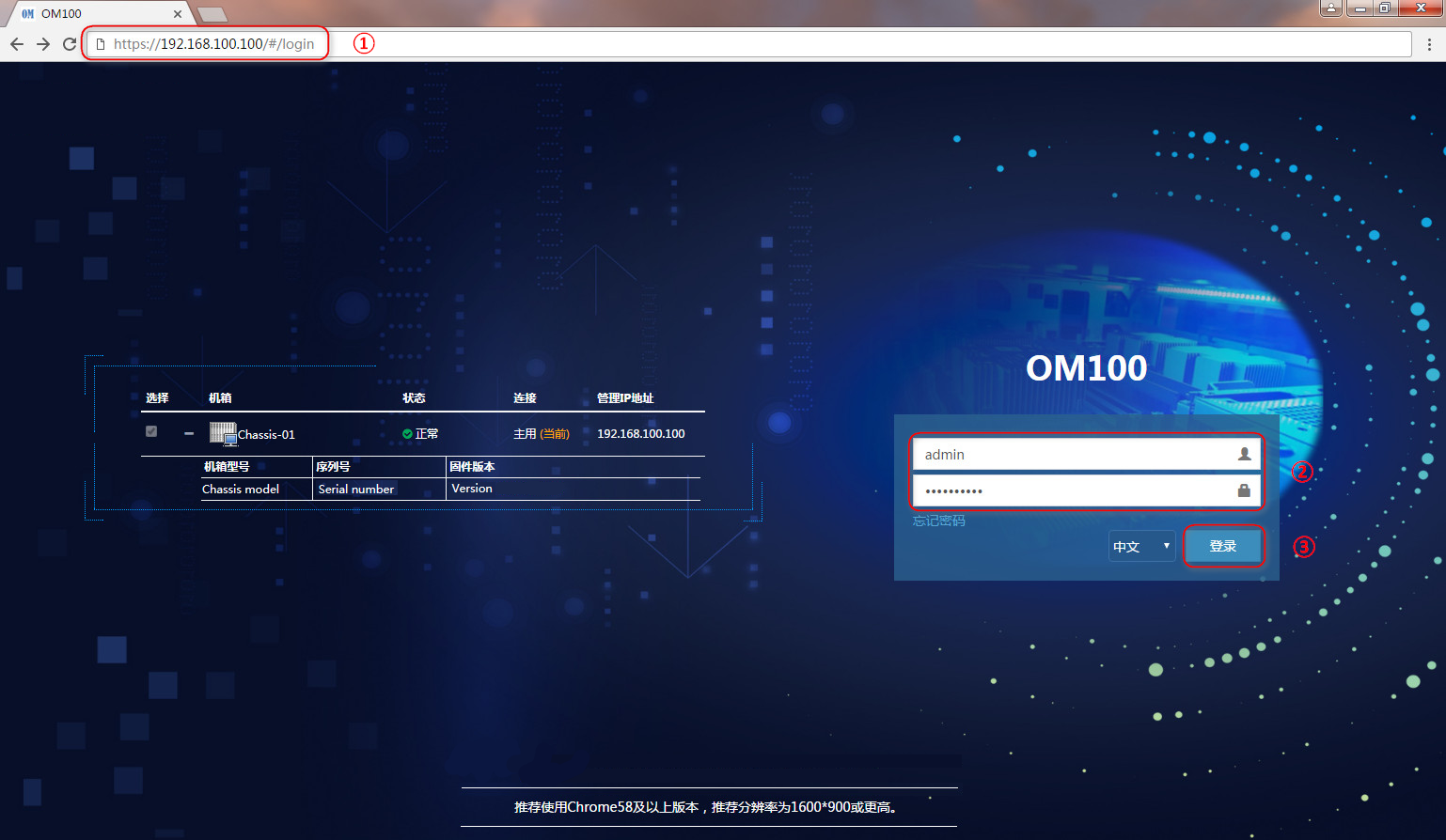
a. As shown by callout 1 in Figure 1, open your browser on your PC and enter the OM Web management IP (in the format of https://OM_ip_address)
b. As shown by callout 2 in Figure 1, enter the username and password.
c. As shown by callout 3 in Figure 1, click Login.
Figure 1 Logging in to the OM Web interface
3. Perform the following tasks to power on the switch module.
a. Click Interconnect Module Management.
b. Select the target switch module.
c. Click Virtual Power and then select Power On.
d. Click OK.
Powering on the switch module from the OM CLI
1. Open a remote access program, set the SSH login parameters, and log in to the OM CLI.
Table 4 SSH login parameters
|
Parameter |
Setting |
|
Protocol |
SSH |
|
Port number |
22 |
|
OM management IP |
· Management IP address (default): 192.168.100.100 · Subnet mask (default): 255.255.255.0 |
|
OM username and password |
· Username (default): admin · Password (default): Password@_ |
|
· By default, SSH access to OM CLI is enabled. · Data in this table is used as an example. |
|
2. Information as follows is displayed after you access the OM CLI.
******************************************************************************
* Copyright (c) 2004-2020 New H3C Technologies Co., Ltd. All rights reserved.*
* Without the owner's prior written consent, *
* no decompiling or reverse-engineering shall be allowed. *
******************************************************************************
<OM>
3. Execute the io on CPU 1 command to power on the target switch module.
In this example, the switch module in slot 1 is powered on.
<OM> io 1 CPU on
4. Execute the display io list command to verify that the switch module in slot 1 has been powered on.
<OM>display io list
Slot : 1
Running status : Normal
UID LED : Off
PSU : On
Management URL : http://192.168.200.1/web/index.html
Product name : BX1010E
CPU usage : 15%
Powering off the switch module
Power-off methods
The switch module supports the following power-off methods.
Table 5 Switch module power-off methods
|
Power-off method |
Application scenario |
|
Together with the server |
N/A |
|
From the OM Web interface |
The switch module is operating on the server. |
|
From the OM CLI |
Procedure
When the switch module is powered off, its health LED is off. For the health LED location on the module, see "LEDs and buttons."
Powering off the switch module together with the server
The switch module will be powered off automatically when the server is powered off. You are not required to perform any extra operation.
Powering off the switch module from the OM Web interface
1. Obtain required information.
Table 6 Obtaining required information
|
Parameter |
Setting |
|
OM management IP |
· Management IP address (default): 192.168.100.100 · Subnet mask (default): 255.255.255.0 |
|
OM username and password |
· Username (default): admin · Password (default): Password@_ |
|
Slot where the switch module resides |
1 |
|
Data in this table is used as an example. |
|
2. Log in to the OM Web interface.
a. As shown by callout 1 in Figure 2 open your browser on your PC and enter the OM Web management IP (in the format of https://OM_ip_address)
b. As shown by callout 2 in,Figure 2 enter the username and password.
c. As shown by callout 3 in,Figure 2 click Login.
Figure 2 Logging in to the OM Web interface
3. Perform the following operations to power off the switch module.
a. Click Interconnect Module Management.
b. Select the target switch module.
c. Click Virtual Power and then select Power Off.
d. Click OK.
Powering off the switch module from the OM CLI
1. Open a remote access program, set the SSH login parameters, and log in to the OM CLI.
Table 7 SSH login parameters
|
Parameter |
Setting |
|
Protocol |
SSH |
|
Port number |
22 |
|
OM management IP |
· Management IP address (default): 192.168.100.100 · Subnet mask (default): 255.255.255.0 |
|
OM username and password |
· Username (default): admin · Password (default): Password@_ |
|
· By default, SSH access to OM CLI is enabled. · Data in this table is used as an example. |
|
2. Information as follows is displayed after you access the OM CLI.
******************************************************************************
* Copyright (c) 2004-2020 New H3C Technologies Co., Ltd. All rights reserved.*
* Without the owner's prior written consent, *
* no decompiling or reverse-engineering shall be allowed. *
******************************************************************************
<OM>
3. Execute the io 1 CPU off command to power off the target switch module.
Switch module in slot 1 is powered off in this example.
<OM> io 1 CPU off
4. Execute the display io list command to verify that the switch module in slot 1 has been powered off.
<OM>display io list
Slot : 1
Running status : Normal
UID LED : Off
PSU : Off
Management URL :
Product name : BX1010E
CPU usage : 0%
Configuring the switch module
Examples are used in this section for your better understanding.
Accessing the switch module
Obtaining required data
Before accessing the switch module, obtain required data as shown in Table 8.
|
Parameter |
Setting |
|
OM management IP |
· Management IP address (default): 192.168.100.100 · Subnet mask (default): 255.255.255.0 |
|
OM username and password |
· Username (default): admin · Password (default): Password@_ |
|
Slot where the switch module resides |
1 |
|
Data in this table is used as an example. |
|
Accessing the switch module from the SYS serial port (console port)
Prerequisites
· The switch module has been powered on. For information about powering on the switch module, see "Powering on the module."
· You have connected your PC to the SYS serial port (console port) on the switch module. For the location of the console port, see "External ports."
Procedure
1. Open a remote access program and set the login parameters.
Table 9 Login parameters
|
Setting |
|
|
Serial line to connect to |
COMn. n is an integer and represents the console port number. |
|
Speed (baud) |
9600 (default) |
|
Data bits |
8 (default) |
|
Stop bits |
1 (default) |
|
Parity |
None (default) |
|
Flow control |
None (default) |
2. The following information is displayed after you access the CLI of the switch module.
********************************************************************************
* Copyright (c) 2004-2019 New H3C Technologies Co., Ltd. All rights reserved. *
* Without the owner's prior written consent, *
* no decompiling or reverse-engineering shall be allowed. *
********************************************************************************
<Sysname>
Accessing the switch module through SOL serial port redirection
Prerequisites
· The switch module has been powered on. For information about powering on the switch module, see "Powering on the module."
· You have accessed the OM CLI. For information about accessing the OM CLI, see "Accessing the OM CLI."
Procedure
Execute the sol connect command to access the CLI of the target switch module.
The switch module in slot 1 is used in this example.
<OM>sol connect io 1
Begin to edit commands.
<Sysname>%Jul 29 13:42:35:975 2013 H3C SHELL/5/SHELL_LOGIN: Console logged in from c
on1.
<Sysname>
|
|
NOTE: After accessing the switch module CLI through SOL serial port redirection, you can enter "~" and "." in sequence in any view ("~" will not be displayed on the CLI) and then press Enter to return to the CLI of the OM module. |
Configuring a management IP address for the switch module
Obtaining and planning related data
Obtain and plan related data as described in Table 10 before configuring a management IP address for the switch module.
Table 10 Obtaining and planning related data
|
Parameter |
Setting |
|
Data to obtain |
|
|
OM management IP |
· Management IP address (default): 192.168.100.100 · Subnet mask (default): 255.255.255.0 |
|
OM username and password |
· Username (default): admin · Password (default): Password@_ |
|
Slot where the switch module resides |
1 |
|
Data to plan |
|
|
Switch module |
· IP address: 192.168.200.1 · Subnet mask: 255.255.255.0 · Gateway: 192.168.200.254 |
|
Data in this table is used as an example. |
|
Configuring a management IP address from the OM Web interface
Prerequisites
· The switch module has been powered on. For information about powering on the switch module, see "Powering on the module."
· You have accessed the OM Web interface. For information about accessing the OM Web interface, see "Accessing the OM Web interface."
Procedure
1. Click Chassis Management, and then select Chassis Management > Slot IP Address Management > Interconnect Module Slot IP.
2. Enable IPv4 management address configuration for the target switch module, configure the management IP address settings, and then click Apply.
3. Click OK in the dialog box that opens.
To save the current configuration of the switch module, click Saving to the configuration file before clicking OK.
Configuring a management IP address from the OM CLI
Prerequisites
· The switch module has been powered on. For information about powering on the switch module, see "Powering on the module."
· You have accessed the OM CLI. For information about accessing the OM CLI, see "Accessing the OM CLI."
Procedure
Execute the auto-ipv4 command to configure the management IP address for the switch module. This example configures the management IP address for the switch module in slot 1. When configuring the management IP address, you can select to save the configuration to the configuration file or not.
· To configure the management IP address for the switch module with the configuration saved to the configuration file, execute the following command:
<OM>auto-ipv4 address 192.168.200.1 mask 255.255.255.0 gateway 192.168.200.254 io 1 save enable
· To configure the management IP address for the switch module without saving the configuration to the configuration file, execute the following command:
<OM>auto-ipv4 address 192.168.200.1 mask 255.255.255.0 gateway 192.168.200.254 io 1 save disable
Configuring a management IP address from the switch module CLI
Prerequisites
· The switch module has been powered on. For information about powering on the switch module, see "Powering on the module."
· You have accessed the switch module. For information about accessing the switch module, see "Accessing the switch module."
Procedure
For the configuration procedure, see the configuration guide and command reference for H3C UniServer BX1010E switch module.
Splitting a 100-GE interface and combining breakout interfaces into a 100-GE interface
You can use a 100-GE interface on the switch module as a single interface. To improve port density, reduce costs, and improve network flexibility, you can also split a 100-GE interface into four breakout interfaces.
The breakout interfaces split from a 100-GE interface support the same configuration and features as common physical interfaces, except that they are numbered differently.
For example:
· You can split 100-GE interface HundredGigE 1/1/9 into four 25-GE interfaces Twenty-FiveGigE 1/1/9:1 through Twenty-FiveGigE 1/1/9:4.
· You can split 100-GE interface HundredGigE 1/1/9 into four 10-GE interfaces Ten-GigabitEthernet 1/1/9:1 to Ten-GigabitEthernet 1/1/9:4.
If you need higher bandwidth on a single interface, you can combine the breakout interfaces into a 100-GE interface.
By default, a 100-GE interface is not split and operates as a single interface.
Prerequisites
· The switch module has been powered on. For information about powering on the switch module, see "Powering on the module."
· You have accessed the switch module. For information about accessing the switch module, see "Accessing the switch module."
· Be sure that you are clear about the restrictions and guidelines for splitting and combining interfaces. For more information, see the configuration guides and command references for the H3C UniServer BX1010E switch module.
· To split a 100-GE interface into four 25-GE interfaces, you need a 100-GE transceiver module or cable that support splitting for connection. To split a 100-GE interface into four 10-GE interfaces, you need a 40-GE transceiver module or cable that support splitting for connection.
Splitting a 100-GE interface into four 25-GE interfaces
1. Enter the CLI of the switch module.
2. Enter system view.
<Sysname> system-view
3. Enter 100-GE interface view. HundredGigE 1/1/9 is used in this example.
[Sysname] interface hundredgige 1/1/9
[Sysname-HundredGigE1/1/9]
4. Execute the using twenty-fivegige command to split the 100-GE interface into four 25-GE breakout interfaces.
[Sysname-HundredGigE1/1/9] using twenty-fivegige
The interface HundredGigE1/1/9 will be deleted. Continue? [Y/N]:y
Splitting a 100-GE interface into four 10-GE interfaces
1. Enter the CLI of the switch module.
2. Enter system view.
<Sysname> system-view
3. Enter 100-GE interface view. HundredGigE 1/1/9 is used in this example.
[Sysname] interface hundredgige 1/1/9
[Sysname-HundredGigE1/1/9]
4. Execute the using tengige command to split the 100-GE interface into four 10-GE breakout interfaces.
[Sysname-HundredGigE1/1/9] using tengige
The interface HundredGigE1/1/9 will be deleted. Continue? [Y/N]:y
Combining breakout interfaces into a 100-GE interface
1. Enter the CLI of the switch module.
2. Enter system view.
<Sysname> system-view
3. Enter the view of any breakout interface.
¡ If the 100-GE interface is split into 25-GE breakout interfaces, execute the interface twenty-fivegige command to enter the view of any 25-GE breakout interface. Twenty-FiveGigE 1/1/9:1 is used in this example.
[Sysname] interface twenty-fivegige 1/1/9:1
¡ If the 100-GE interface is split into 10-GE breakout interfaces, execute the interface ten-gigabitethernet command to enter the view of any 10-GE breakout interface. Ten-GigabitEthernet 1/1/9:1 is used in this example.
[Sysname] interface ten-gigabitethernet 1/1/9:1
4. Execute the using hundredgige command to combine breakout interfaces into a 100-GE interface.
¡ To combine 25-GE breakout interfaces into a 100-GE interface:
[Sysname-Twenty-FiveGigE1/1/9:1] using hundredgige
The interfaces Twenty-FiveGigE 1/1/9:1 through Twenty-FiveGigE 1/1/9:4 will be deleted. Continue? [Y/N]:y
¡ To combine 10-GE breakout interfaces into a 100-GE interface:
[Sysname-Ten-GigabitEthernet1/1/9:1]using hundredgige
The interfaces Ten-GigabitEthernet1/1/9:1 through Ten-GigabitEthernet1/1/9:4 will be deleted. Continue? [Y/N]:y
|
|
IMPORTANT: After splitting or combining interfaces, you must execute the save command and reboot the device for the configuration to take effect. After the device is rebooted, you can view information about the split or combined interfaces from the display interface brief command output. |
Configuring switch module services
Prerequisites
· The switch module has been powered on. For information about powering on the switch module, see "Powering on the module."
· You have accessed the switch module. For information about accessing the switch module, see "Accessing the switch module."
· You have planned the services to configure for the switch module.
Procedure
For the configuration procedure, see the configuration guide and command reference for H3C UniServer BX1010E switch module.
Saving the configuration file
Prerequisites
· The switch module has been powered on. For information about powering on the switch module, see "Powering on the module."
· You have accessed the switch module. For information about accessing the switch module, see "Accessing the switch module.
Procedure
1. Access user view of the switch module at the CLI. Execute the dir command to view the current file system of the switch module, identify the next-startup configuration file name, and verify that the flash has sufficient space to accommodate a new startup configuration file.
<Sysname> dir
Directory of flash:
0 drw- - Apr 17 2019 17:43:29 diagfile
1 drw- - Apr 08 2019 14:49:27 flyfishlog
2 -rw- 412 Apr 29 2019 10:50:54 ifindex.dat
3 drw- - Apr 17 2019 17:43:29 logfile
4 drw- - Apr 08 2019 14:51:51 pki
5 drw- - Apr 08 2019 14:49:17 seclog
6 -rw- 2649 Apr 29 2019 10:50:54 startup.cfg
7 -rw- 669171 Apr 29 2019 10:50:55 startup.mdb
8 -rw- 5705728 Apr 28 2019 14:35:55 uis-cmw710-boot-1.00.10.bin
9 -rw- 108381184 Apr 28 2019 14:36:52 uis-cmw710-system-1.00.10.bin
10 -rw- 7168 Apr 29 2019 14:06:09 uis.db
11 -rw- 7168 Apr 29 2019 14:06:09 uis_bak.db
12 drw- - Apr 22 2019 11:19:19 versionInfo
<Sysname>
2. From any view of the switch module, execute the save command to save the current configuration information.
<Sysname> save
The current configuration will be written to the device. Are you sure? [Y/N]:y
Please input the file name(*.cfg)[flash:/startup.cfg]
(To leave the existing filename unchanged, press the enter key):
flash:/startup.cfg exists, overwrite? [Y/N]:y
Validating file. Please wait...
Saved the current configuration to mainboard device successfully.
<Sysname>
3. From user view of the switch module, execute the tftp put command to back up the system image file and next-startup configuration file to an TFTP server.
<Sysname>tftp 192.168.1.1 put flash:/uis-cmw710-system-1.00.10.bin
Press CTRL+C to abort.
% Total % Received % Xferd Average Speed Time Time Time Current
Dload Upload Total Spent Left Speed
84 103M 0 0 84 87.0M 0 851k 0:02:04 0:01:44 0:00:20 837k
<Sysname>tftp 192.168.1.1 put flash:/uis-cmw710-boot-1.00.10.bin
Press CTRL+C to abort.
% Total % Received % Xferd Average Speed Time Time Time Current
Dload Upload Total Spent Left Speed
100 5572k 0 0 100 5572k 0 832k 0:00:06 0:00:06 --:--:-- 828k
<Sysname>
4. From user view of the switch module, execute the tftp put command to back up the filestartup.cfg configuration file to the TFTP server.
<Sysname>tftp 192.168.1.1 put startup.cfg
Press CTRL+C to abort.
% Total % Received % Xferd Average Speed Time Time Time Current
Dload Upload Total Spent Left Speed
100 6549 0 0 100 6549 0 270k --:--:-- --:--:-- --:--:-- 319k
<Sysname>
Common operations
Accessing the OM Web interface
Prerequisites
· The server has been powered on.
· Data required for accessing the OM Web interface has been obtained.
Procedure
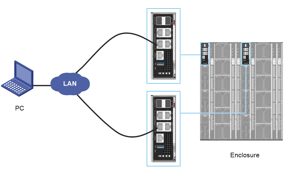
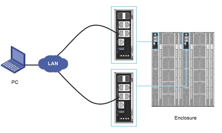
1. As shown in Figure 3, connect the Ethernet port on your PC to the MGMT port on the active and standby OM modules over the LAN. Make sure the PC and OM module management network are reachable to each other at Layer 3.
Figure 3 Setting up the environment for accessing the OM Web interface
2. Log in to the OM Web interface.
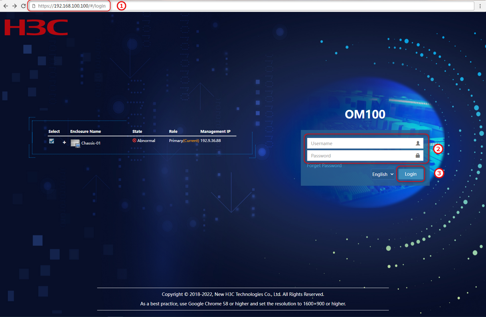
a. As shown by callout 1 in,Figure 4 open your browser on the your PC and enter the OM Web management IP (in the format of https://OM_ip_address)
b. As shown by callout 2 in Figure 4,enter the username and password.
c. As shown by callout 3 in Figure 4, click Login.
Figure 4 Logging in to the OM Web interface

Accessing the OM CLI
Prerequisites
· The server has been powered on.
· Data required for accessing the CLI has been obtained.
Procedure
1. As shown in Figure 5, connect the Ethernet port on your PC to the MGMT port on the active and standby OM modules over the LAN. Make sure the PC and OM module management network are reachable to each other at Layer 3.
Figure 5 Setting up the environment for accessing the OM CLI
2. Log in to the OM CLI.
a. As shown by callout 1 in,Figure 6 open your browser on the your PC and enter the OM Web management IP (in the format of https://OM_ip_address)
b. As shown by callout 2 in,Figure 6 enter the username and password.
c. As shown by callout 3 in Figure 6, click Login.
Figure 6 Logging in to the OM Web interface

3. Open a remote access software, set the SSH login parameters, and log in to the OM CLI.
Table 11 SSH login parameters
|
Parameter |
Description |
|
Protocol |
SSH |
|
Port number |
22 |
|
OM management IP |
· Management IP address (default): 192.168.100.100 · Subnet mask (default): 255.255.255.0 |
|
OM username and password |
· Username (default): admin · Password (default): Password@_ |
|
· By default, SSH access to OM CLI is enabled. · Data in this table is used as an example. |
|
4. Information as follows is displayed after you access the OM CLI.
******************************************************************************
* Copyright (c) 2004-2019 New H3C Technologies Co., Ltd. All rights reserved.*
* Without the owner's prior written consent, *
* no decompiling or reverse-engineering shall be allowed. *
******************************************************************************
<OM>
Upgrading firmware
For information about the firmware upgrade procedure, see H3C UniServer B16000 Blade Server Upgrade Guide.
