- Table of Contents
- Related Documents
-
| Title | Size | Download |
|---|---|---|
| 02-Appendix | 2.88 MB |
Appendix A Install diskless boot-compatible OS
Configure an IP address of the AE module
Configure an Ethernet adapter of the server through BIOS
Access the KVM console of a blade server (for AE modules only)
Configure the IP address of the FIST server
Appendix A Install diskless boot-compatible OS
Overview
Complying with iSCSI, diskless boot provided by FIST allows servers to boot the operating system from a remote storage volume instead of a local drive. You can manually install operating systems in the storage volume to implement diskless boot.
OSs that support diskless boot include the following:
· Red Hat Enterprise Linux 7.5 (64 bit)
· CentOS 7.5 (64 bit)
· VMware ESXi 6.5 U2 (64 bit)
· VMware ESXi 6.7 (64 bit)
Restrictions and guidelines
When using diskless boot, as a best practice, use the local drives only as data drives, and make sure the local drives have no OS installed and have no system boot programs. Otherwise, the diskless boot process might be affected after an OS is installed.
Procedure
Install FIST
For information about how to install FIST, see FIST Installation Guide.
Prepare the OS image file
Download the .iso image file of the OS from the official website of the OS.
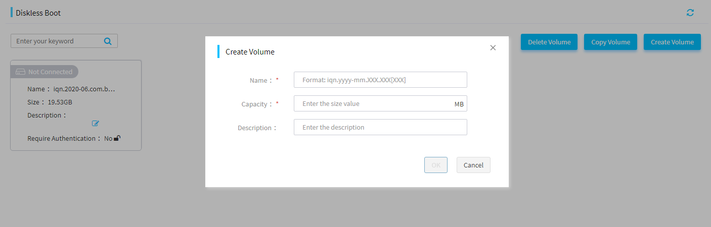
Create a storage volume
1. Log in to FIST.
2. In the navigation pane, select Menu > Templates > Diskless Boot.
3. Click Create Volume and create a volume.
Figure 1 Creating a volume
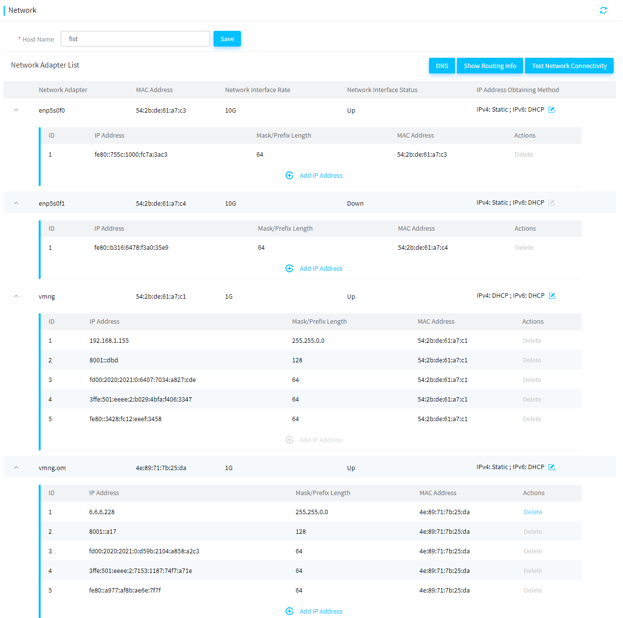
Configure an IP address of the AE module
If the FIST server runs on an AE module, the following network ports are available:
· vmng—Network port connected to the service network port of the OM module.
· vmng.om—Network port connected to the management network port of the OM module.
· enp5s0f0—Network port connected to interconnect module 1.
· enp5s0f1—Network port connected to interconnect module 4.
You must configure the IP address of the network port that connects FIST to the server. This IP address will be used as the IP address of the iSCSI server.
Restrictions and guidelines
If the server and the AE module where the storage volume is created reside in the same enclosure, make sure the Ethernet adapter of the server is connected to Interconnect module 1 or 4.
If the server and the AE module where the storage volume is created reside in different enclosures, make sure the Ethernet adapter of the AE module connects to the server through switches.
Procedure
1. Log in to FIST.
2. In the navigation pane, select Menu > System > Network.
3. Identity the network port that connects FIST to the server.
4. Click Add IP Address to configure the IP address of the network port.
Figure 2 Configuring an IP addresses of the AE module
Configure an Ethernet adapter of the server through BIOS
Procedure
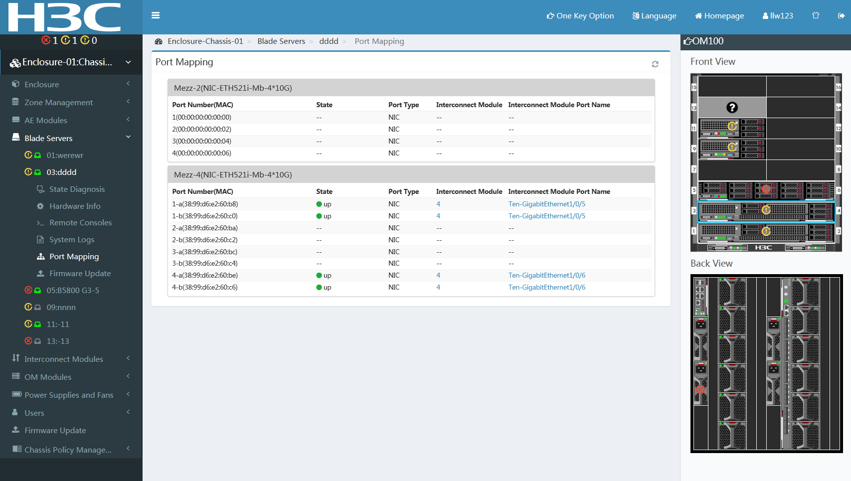
1. Log in to OM of the server, select Blade Servers > Blade_Server > Port Mapping. Then, Identify the location of the Ethernet adapter of the server to perform diskless boot and verify that the interconnect module connected to the Ethernet adapter is present.
Figure 3 Port mapping on the OM
2. Enter the BIOS setup utility, select Advanced, select the Slot x Port x entry of the Ethernet adapter, and press Enter.
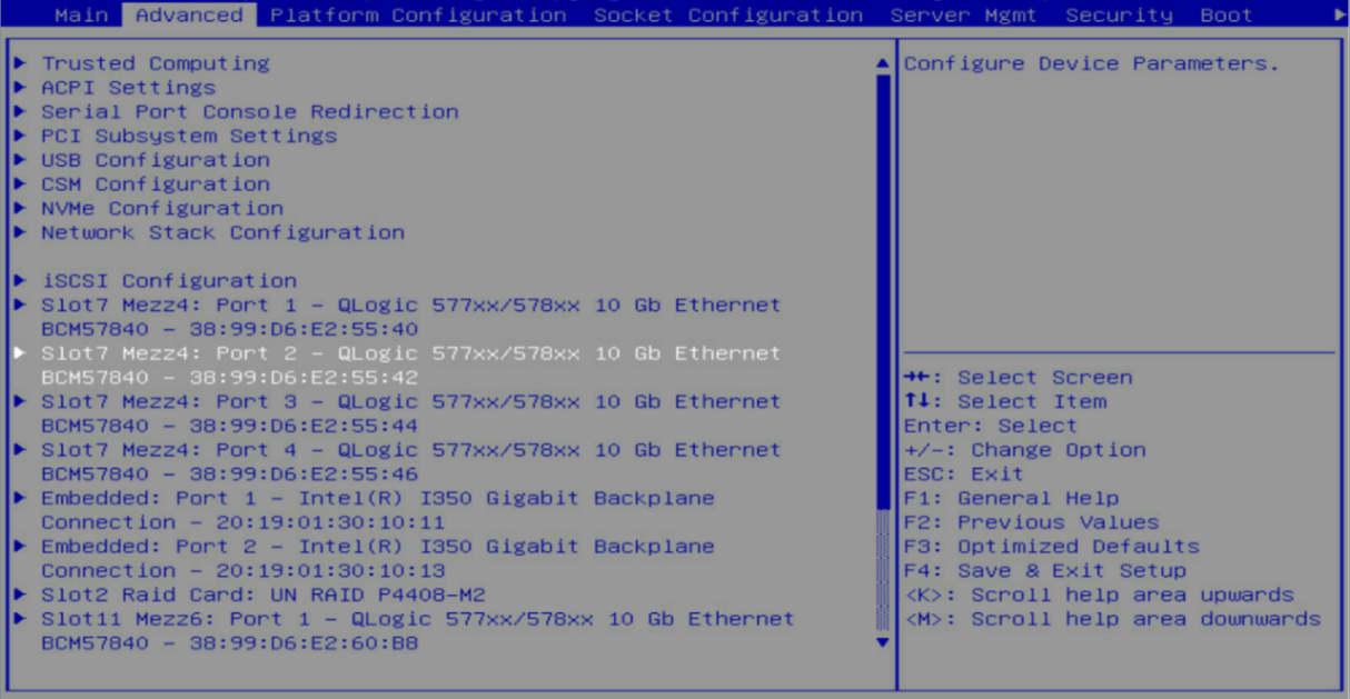
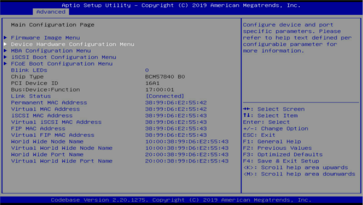
3. Verify that the link status is Connected, and press Enter.
Figure 5 Main Configuration Page screen
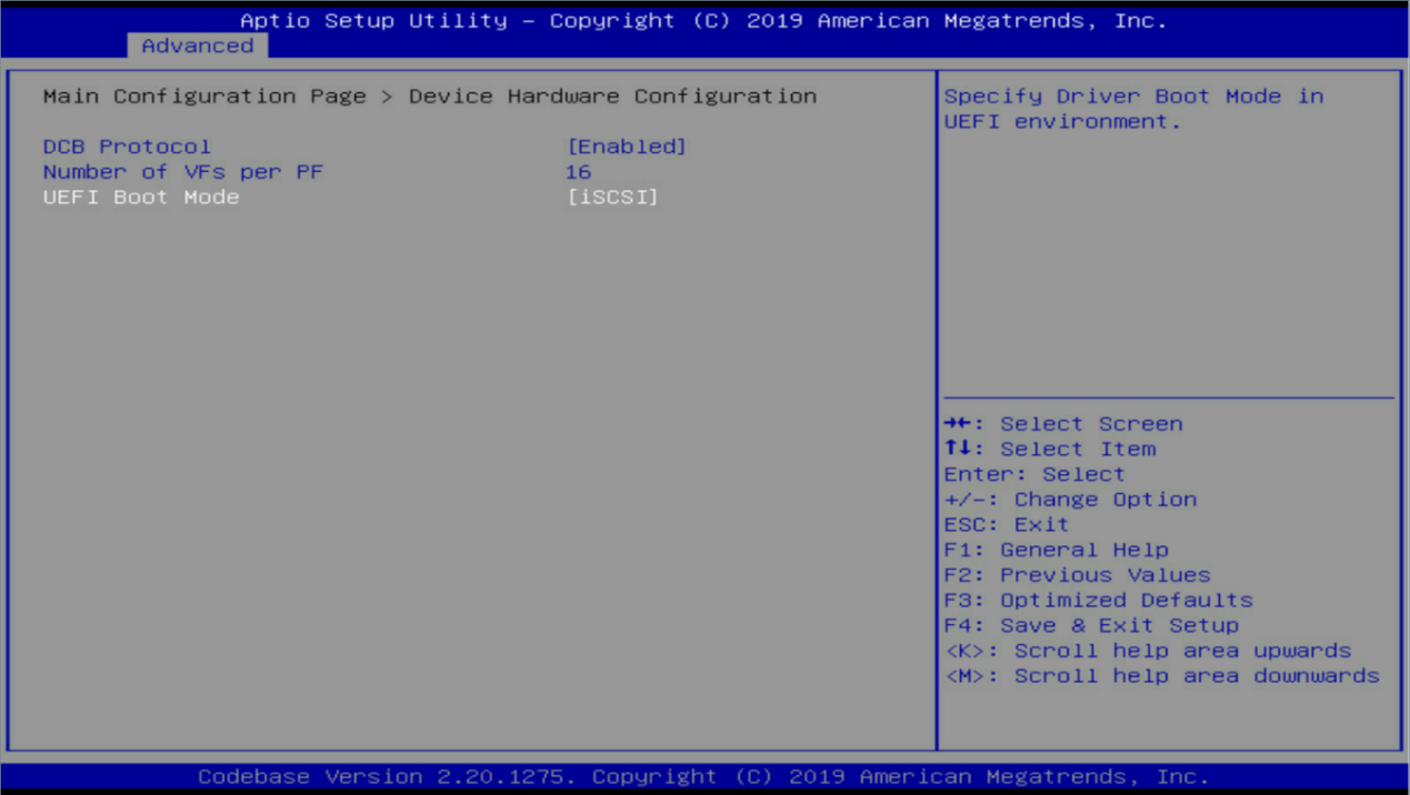
4. Set the UEFI boot mode to iSCSI, and press Enter.
Figure 6 Device Hardware Configuration menu
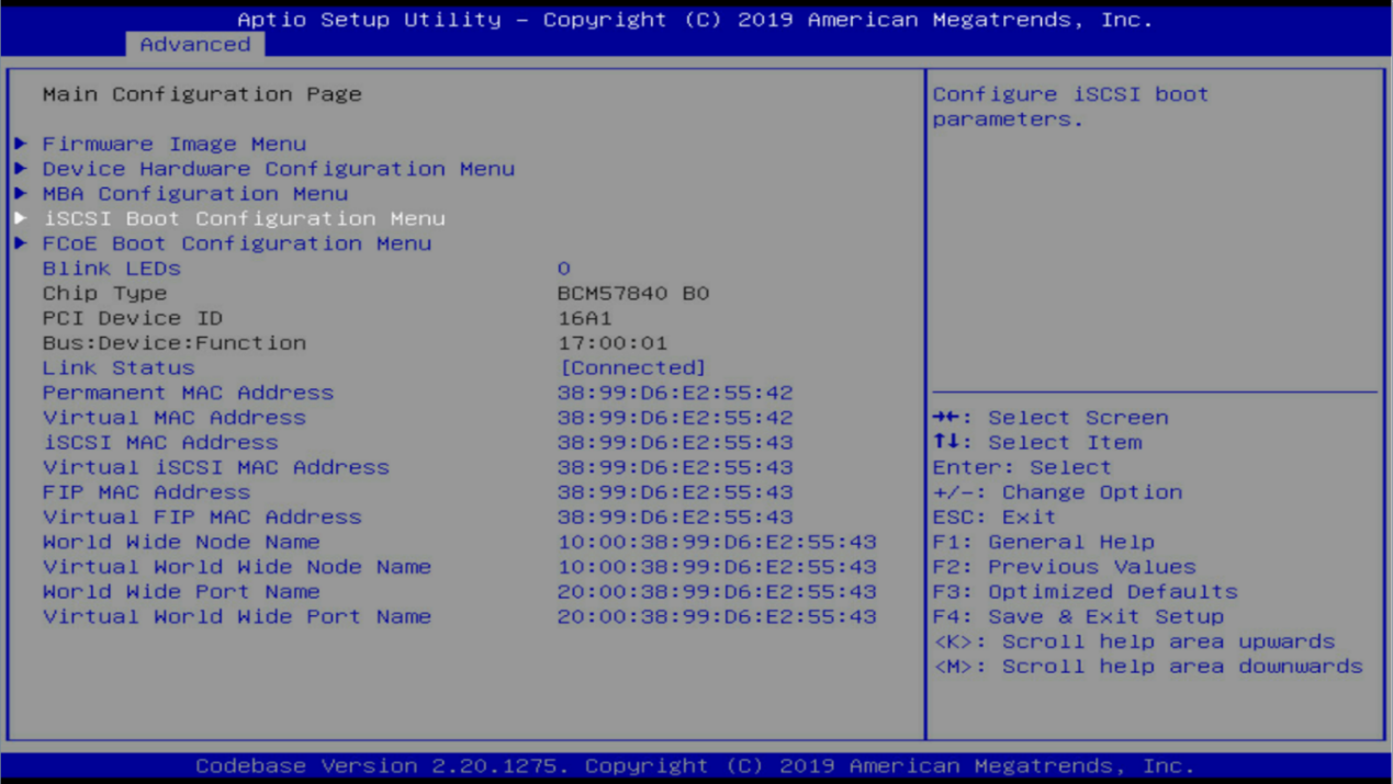
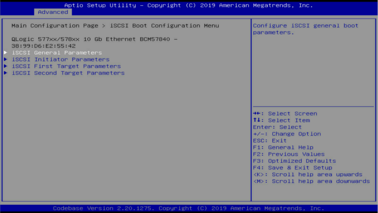
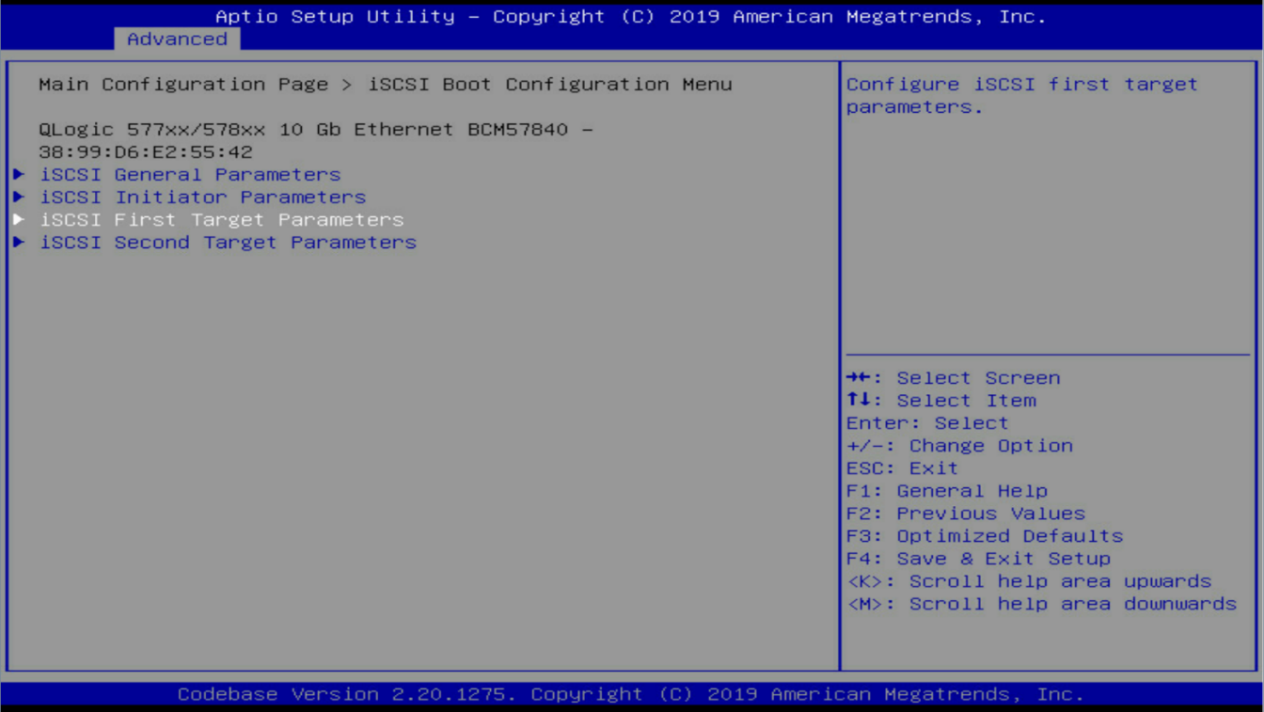
5. Press ESC, select iSCSI Boot Configuration Menu, and press Enter.
Figure 7 Main Configuration Page menu screen
6. Select iSCSI General Parameters, and press Enter.
Figure 8 iSCSI Boot Configuration Menu screen
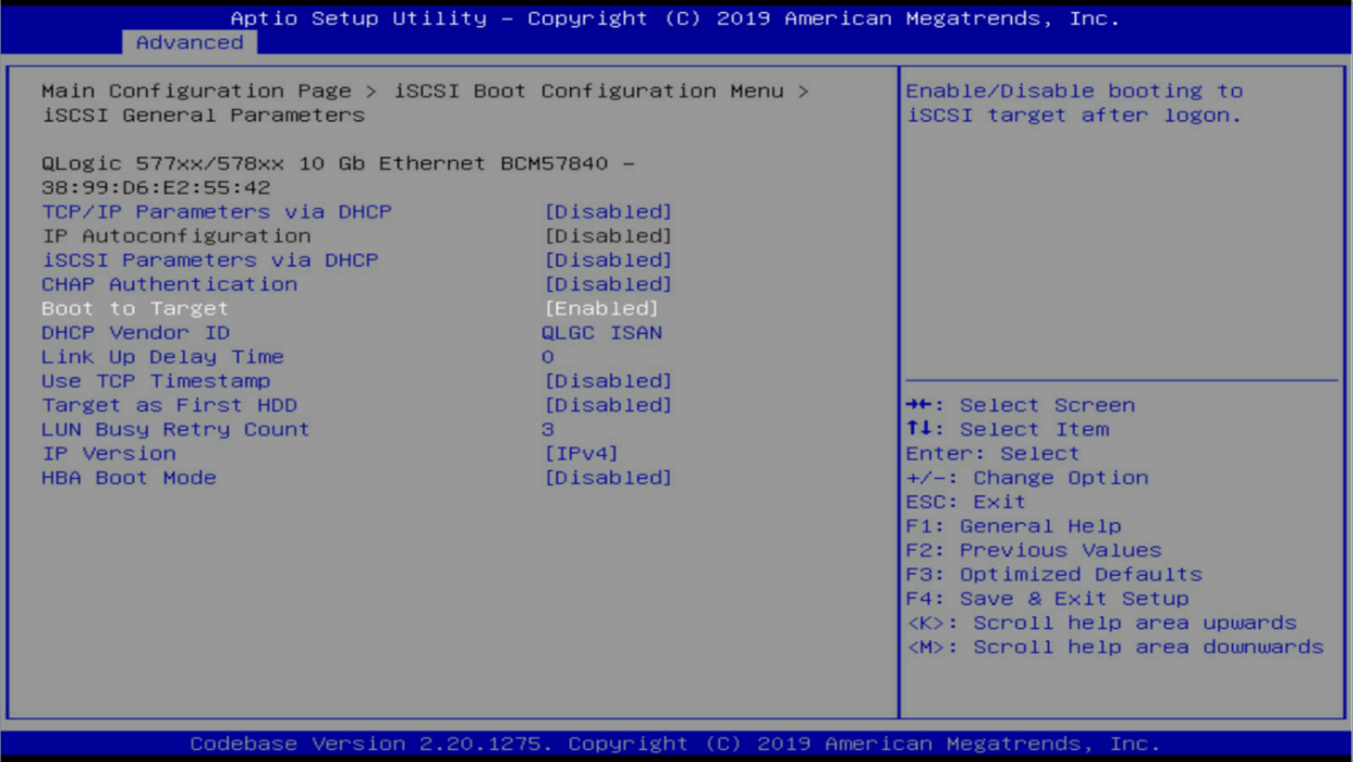
7. Configure the general iSCSI parameters as follows:
a. Enable TCP/IP Parameters via DHCP if you want to use DHCP to assign an IP address to the network port. To statically assign an IP address, disable this parameter.
b. Enable CHAP Authentication if the storage volume is enabled with authentication.
c. Enable Boot to Target.
d. Use the default settings for other parameters.
e. Press Enter.
Figure 9 iSCSI General Parameters submenu screen
8. Press ESC, select iSCSI Initiator Parameters, and press Enter.
Figure 10 iSCSI Boot Configuration Menu screen
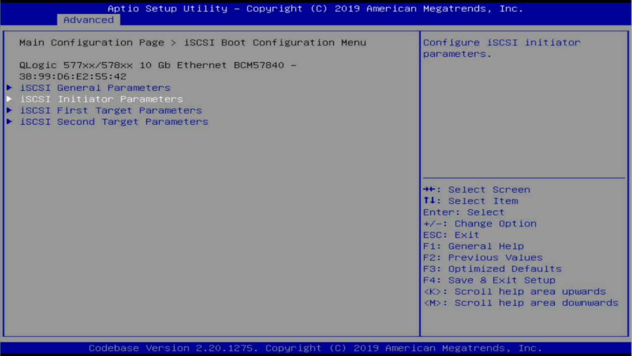
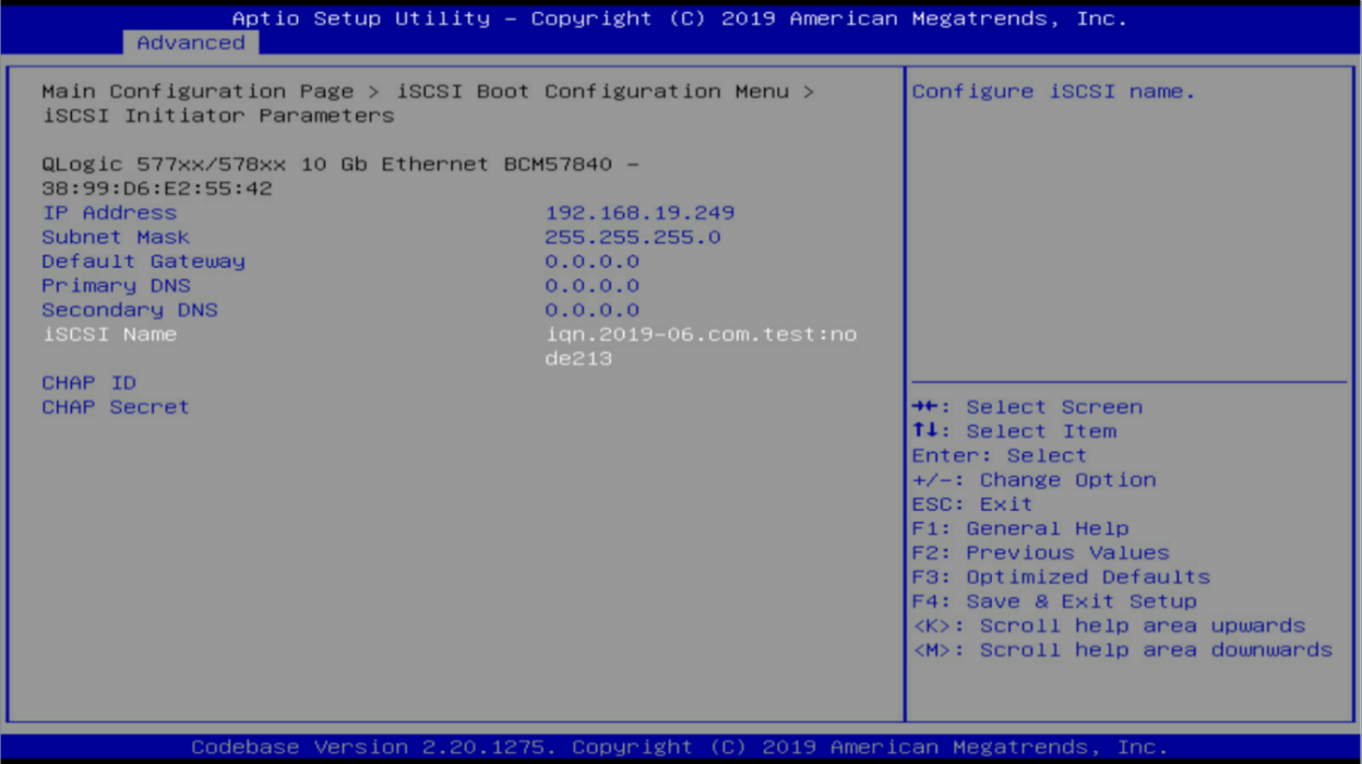
9. Configure the iSCSI initiator parameters as follows:
a. (Optional.) Set the IP address and subnet mask if TCP/IP Parameters via DHCP is disabled. The Ethernet adapter will use the IP address to communicate with the storage volume.
b. (Optional.) Set the default gateway and DNS settings as needed.
c. Set the iSCSI name, the unique IQN name that the Ethernet adapter uses to connect to the storage volume.
d. (Optional.) Set the CHAP ID and CHAP secret (the credentials of the storage volume) if CHAP authentication is enabled for the storage volume.
Each time you edit the iSCSI target parameters, you must reset the CHAP ID and CHAP secret.
Figure 11 iSCSI Initiator Parameters submenu screen
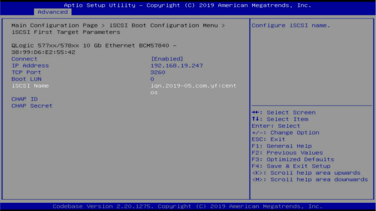
10. Press ESC, select iSCSI First Target Parameters, and press Enter.
Figure 12 iSCSI Boot Configuration Menu screen
11. Configure the iSCSI target parameters as follows:
a. Enable Connect to enable the connection settings.
b. Set the IP address of the iSCSI server, which is the IP address of a network port on the AE module configured in "Configure an IP address of the AE module."
c. Set the iSCSI name, the IQN name of the storage volume created on the AE module.
d. Use the default settings for other parameters.
e. Press Enter.
Figure 13 iSCSI First Target Parameters submenu screen
12. Reboot the server to commit the configuration changes.
Install the OS
You can use different methods to install the OS as needed. This example uses the installation image mounted to KVM of the server.
Prerequisites
Start the KVM of the server, mount the standard installation image, and reboot the server.
Install Redhat/Centos7.5
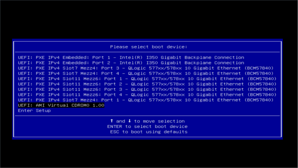
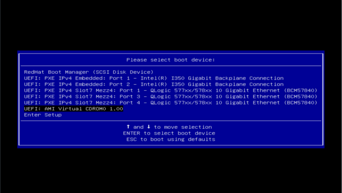
1. Enter the BIOS setup utility of the server.
2. Select the virtual CDROM as the boot device, and press Enter.
Figure 14 Boot menu
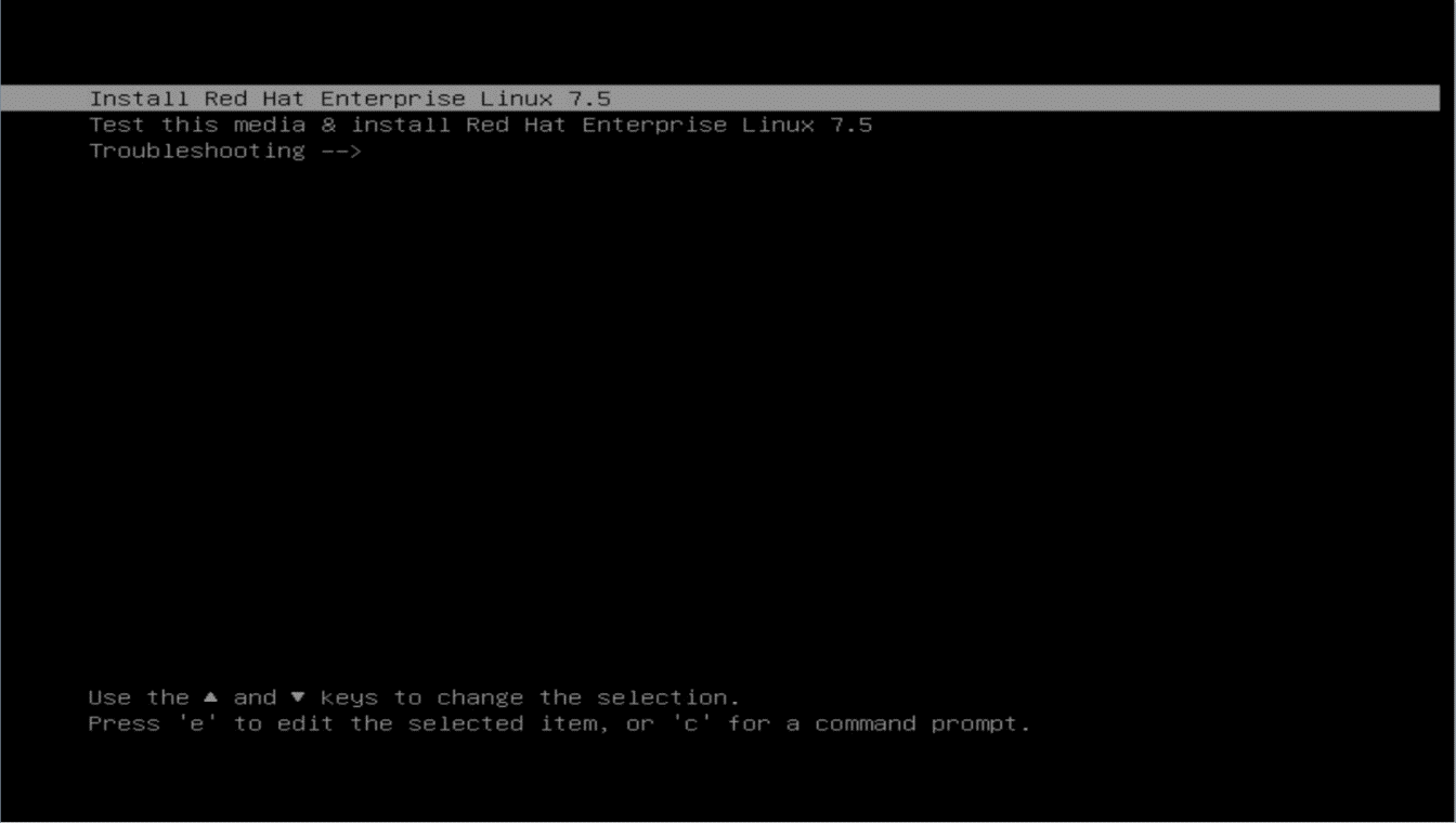
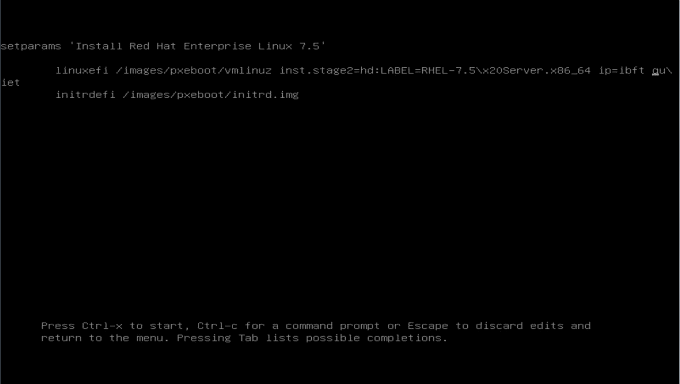
3. On the boot splash screen, select the first or second item, and press e.
Figure 15 Boot splash screen
4. On the second line, enter ip=ibft with leading and ending spaces before quite, and then press Ctrl+x.
Figure 16 Setting parameter screen
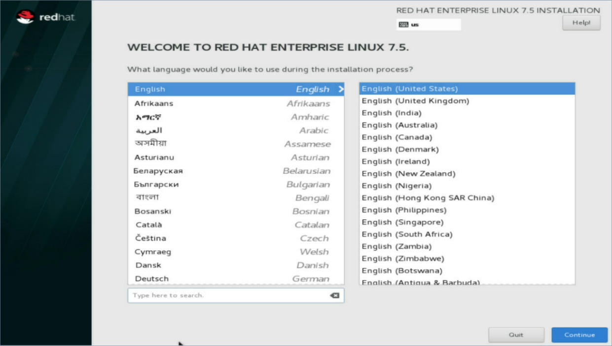
5. On the Welcome screen, select a language, and then click Continue.
Figure 17 Welcome screen
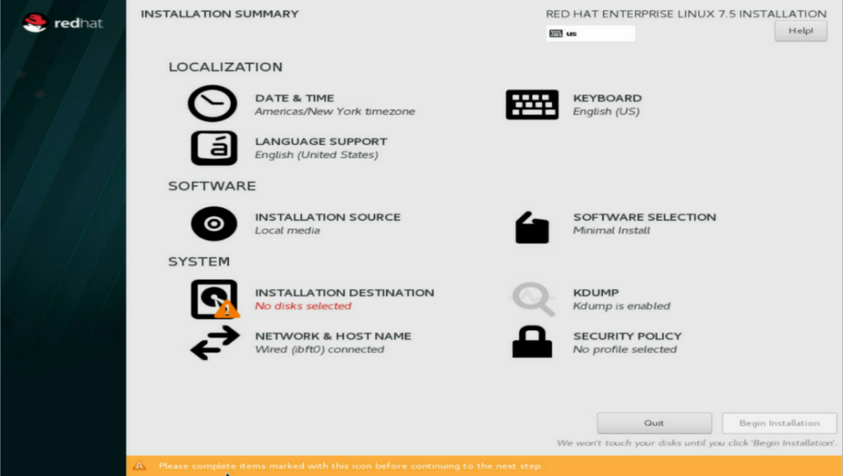
6. On the installation summary screen, verify that the NETWORK & HOSTNAME section displays ibft0 connected, which indicates the system obtains the Ethernet adapter settings on BIOS.
Figure 18 Installation summary screen
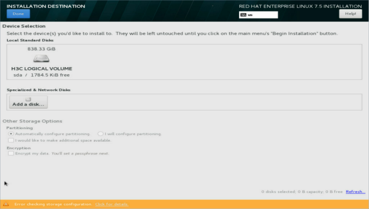
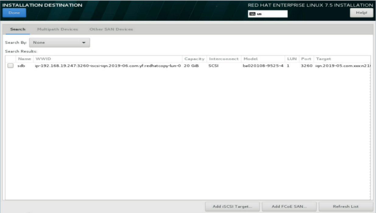
7. Click INSTALLATION DESTINATION to select target installation drives. In this example, the storage volume created on the AE module is used.
8. On the INSTALLATION DESTINATION screen, click Add a disk in the Specialized & Network Disks section. Do not select a local disk in Local Standard Disks.
Figure 19 INSTALLATION DESTINATION screen
9. On the Add a disk screen, verify that the IQN name and capacity of the iSCSI storage controller are correct. Then, select this iSCSI storage controller, and click Done.
If no iSCSI storage controller is displayed, verify that the Ethernet adapter is correctly configured and the network environment is correctly set up.
Figure 20 Add a disk screen
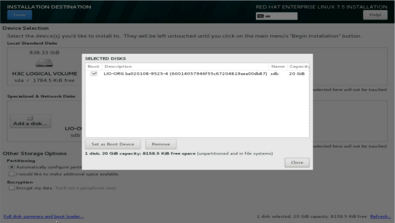
10. On the INSTALLATION DESTINATION screen, click Full disk summary and boot loader at the bottom left corner. Then, on the dialog box that opens, verify the boot device of the iSCSI storage volume is correct, select the boot device, and click Close.
Figure 21 SELECTED DISKS dialog box
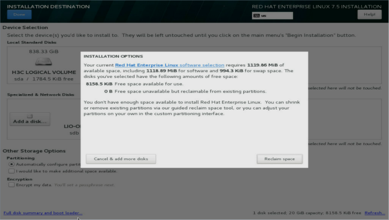
11. Select a partition method for the Partitioning parameter in the Other Storage Options section. This example uses automatic partitioning.
If the iSCSI storage volume already has partitions, the system will prompt you to repartition. Click Reclaim space and then repartition the iSCSI storage volume.
Figure 22 INSTALLATION OPTIONS screen
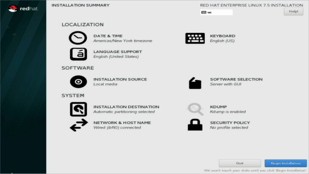
12. Select the required installation image and configure the other installation parameters. For more information, see H3C Servers Operating System Installation Guide.
13. Click Begin Installation, and wait for the installation to finish.
Figure 23 Installation summary screen
14. Reboot the server.
15. (Optional.) You can copy the iSCSI storage volume to perform diskless boot on other servers in FIST.
Install VMware ESXi 6.5 U2/ESXi 6.7
1. Enter the BIOS setup utility of the server.
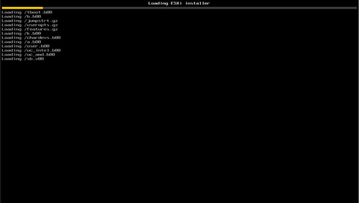
2. Select the virtual CDROM as the boot device, and press Enter. This example uses ESXi 6.5 U2. For ESXi 6.7, the installation procedure is the same.
Figure 24 Boot menu screen
3. Wait for the ESXi installer loading to finish.
Figure 25 loading ESXi installer screen
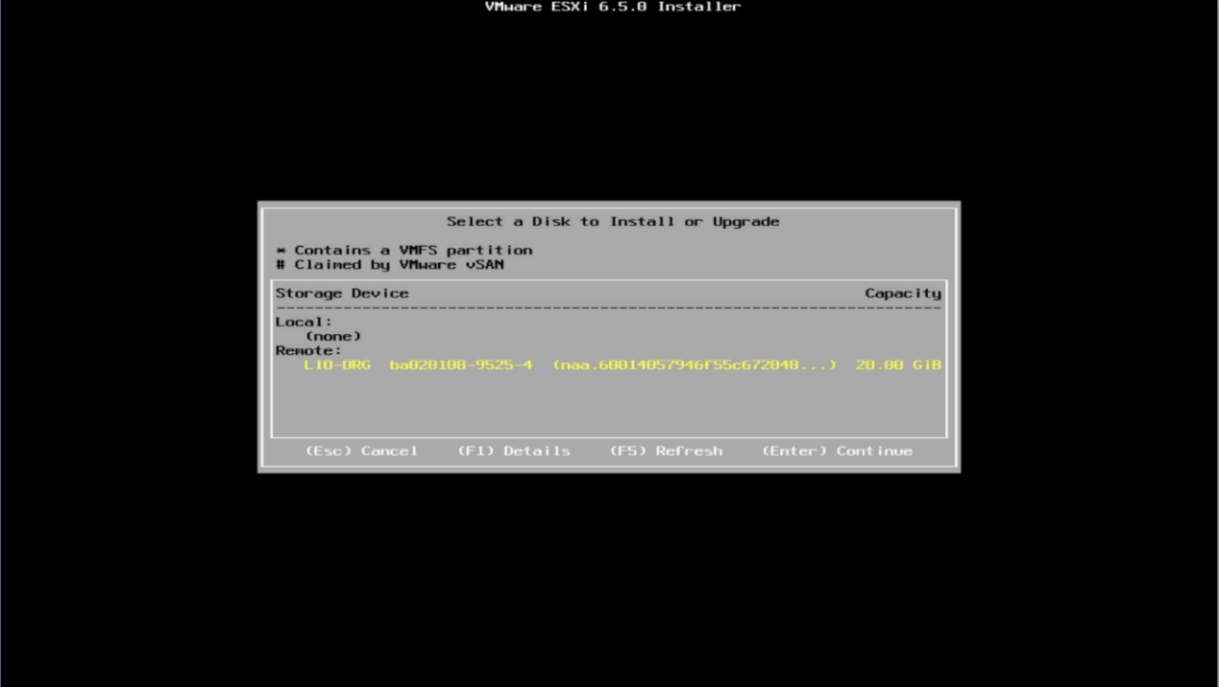
4. On the dialog box that opens, select the iSCSI storage volume, and press Enter.
If no iSCSI storage volume is displayed, verify that the Ethernet adapter is correctly configured and the network environment is correctly set up.
Figure 26 Selecting a drive to install the OS
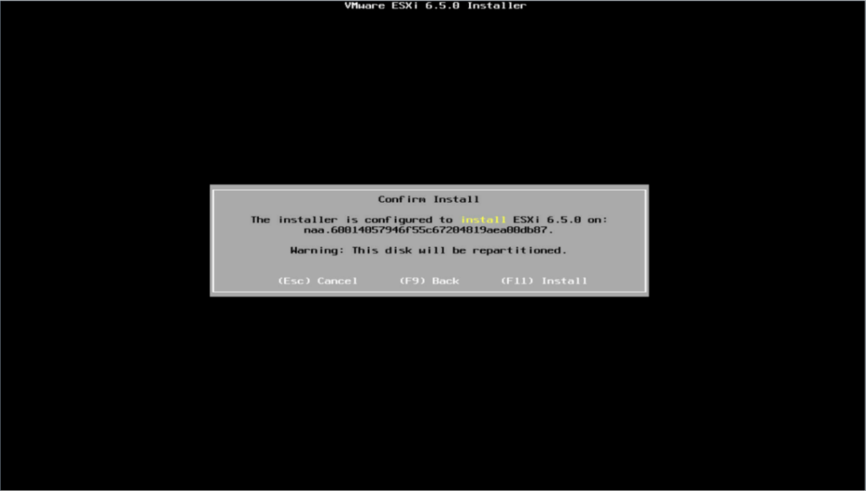
5. (Optional.) On the Confirm Disk Selection dialog box that opens, click OK. If the iSCSI storage volume already has partitions, the system will overwrite the storage volume.
Figure 27 Overwriting the partitions on the drive
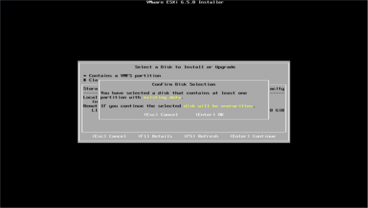
Figure 28 Repartitioning the drive
6. Set the other installation parameters such as the language and root password.
7. Start the installation, and wait for the installation to finish.
8. Reboot the server to enter the ESXi system.
9. (Optional.) You can copy the iSCSI storage volume to perform diskless boot on other servers in FIST.
Appendix B Use FIST VGA
After FIST is installed to an AE module or virtual machine, the function provided by the Web interface of the FIST server is referred to as FIST video graphics array (VGA). On the Web interface of FIST VGA, you can set the server IP and view the blade server systems.
To access FIST VGA, you just need to start the FIST server. No password is required.
Web interface layout
The Web interface of FIST VGA is as shown in Figure 29. The Web interface contains a bar section at the top and a work section, as described in Table 1.
Figure 29 Web interface of FIST VGA
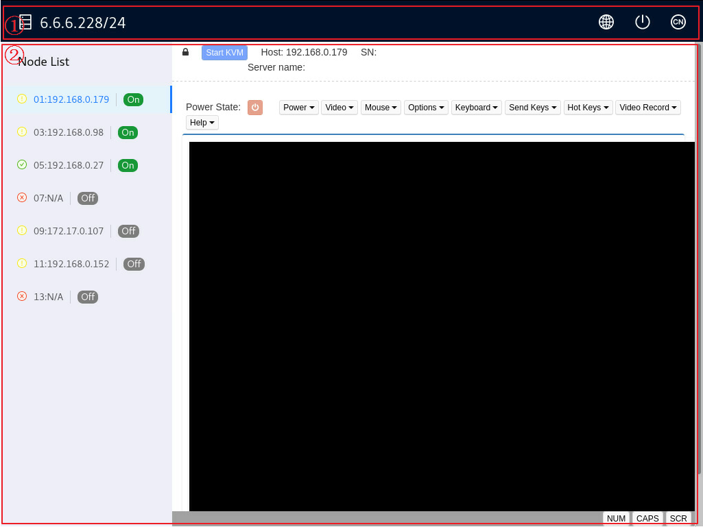
|
Number |
Section |
Description |
|
1 |
Header section |
The IP address of the FIST server is displayed on the left. The following buttons are provided on the right: · · |
|
2 |
Work section |
The node list on the left pane displays the blade server nodes and their status in the AE module. The right pane shows the KVM console of the blade server selected on the left pane. NOTE: For FIST installed to a virtual machine, the work section is blank. |
Functions
Access the KVM console of a blade server (for AE modules only)
1. Access the Web interface of FIST VGA.
The node list on the left displays the HDM IP addresses of all the blade server nodes in the AE module.
2. Select a blade server node.
The KVM console of the blade server is displayed on the right pane.
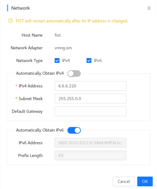
Configure the IP address of the FIST server
1. Access the Web interface of FIST VGA.
2. Click the Network Settings icon ![]() in the upper right corner.
in the upper right corner.
3. In the Network window that opens, set the system IP address of the FIST server.
Figure 30 Configure the IP address of the FIST server