- Table of Contents
- Related Documents
-
| Title | Size | Download |
|---|---|---|
| 01-Text | 8.33 MB |
Content
Connect the FIST server to the network
Obtain the FIST server IP address
General restrictions and guidelines
General restrictions and guidelines
Manage servers remotely through FIST
Use the switch management functions
View enclosure template information
Configure RAID configuration templates
Access the switch template list page
Manage interconnect module templates
Apply an enclosure template to enclosures
Apply an enclosure configuration file
Delete an enclosure configuration file
Enclosure slot configuration files
Apply a server template to servers
Apply a server configuration file
Delete a server configuration file
View a server configuration file
Edit a server configuration file
Delete server configuration files
Apply server configuration files
Update the firmware by using HDM out-of-band management
Manage energy efficiency and prediction (G6 servers)
Configure inlet temperature analysis
Configure server usage analysis
Perform one-key power consumption limit
Configure the DHCP server settings
View the DHCP client information
Configure static IP allocation
Configure PXE OS installation parameters
Incorporate FIST to vCenter Server as a FIST plugin
Configure the network settings
View basic Ethernet adapter information
Set the IP address obtaining method for a network port
Manage the IP addresses of a network port
Synchronize the system time with an NTP server
Configure the security tip for login
View LDAP server information and test connectivity to a server
Introduction
The H3C Fast Intelligent Scalable Toolkit (FIST) is an intelligent, extensible server management software that allows customers to manage servers remotely from a unified, intuitive graphical user interface.
Architecture
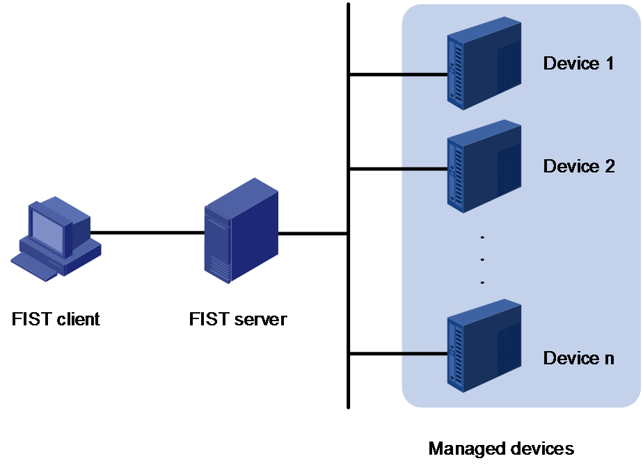
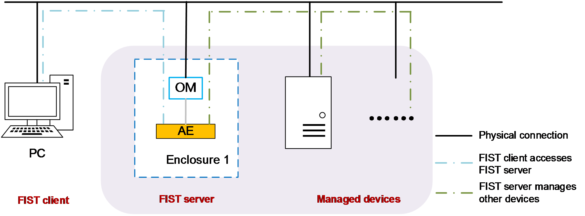
As shown in Figure 1, the FIST architecture contains the following elements:
· FIST client—An endpoint device (such as a PC) used to access FIST through the Web browser.
· FIST server—A PC, physical server, or AE module hosting the FIST server software. The AE module ships with FIST pre-installed.
· Managed devices—Devices managed by FIST.
The FIST client and FIST server can reside on the same device, which means that you can access FIST from the browser of the host where the FIST server resides.
Features
FIST offers the following features:
· Devices—Allows you to centrally manage enclosures, servers, and switches in FIST. You can add devices to FIST, view information about the devices managed by FIST, and manage the devices.
· Templates—Allows you to define templates to deploy BIOS, HDM, RAID, and operating system settings to servers.
· Deployment—Allows you to apply server and enclosure templates for bulk device configuration, and deploy component updates such as firmware and driver updates to servers.
· Monitor—Provides the following capabilities:
¡ Provides visibility into the status of managed servers through reports and operation logs.
¡ Supports forwarding alarms to designated email recipients based on user-defined alarm email notification settings.
The monitor functions help troubleshoot problems and improve operations and maintenance efficiency.
· Tools—Allows you to configure management tools, including the DHCP server, PXE, and FIST SMS.
· System—Provides FIST system configuration and management options. For example, you can configure the system time, network, and backup and restore settings for FIST. You can also manage user accounts in FIST and set up a FIST cluster by teaming up the FIST node up with a secondary node.
The available FIST features vary depending on the environment in which FIST is running:
· In an AE environment, the full set of FIST features is available.
· In a non-AE environment, only the FIST features listed in is available.
Table 1 Features supported by FIST in a non-AE environment
|
Level-1 menu |
Level-2 menu |
Remarks |
|
Devices |
Enclosure List |
See "Manage enclosures." |
|
Server List |
See "Manage servers." |
|
|
Switch List |
See "Manage switches." |
|
|
Templates |
Enclosure Templates |
See "Manage enclosure templates." |
|
Server Templates |
See "Manage server templates." |
|
|
HDM/BIOS Templates |
See "Configure HDM/BIOS templates." |
|
|
Repositories |
See "Configure repositories." |
|
|
Switch Templates |
See "Manage switch templates." |
|
|
Address Pools |
See "Manage address pools." |
|
|
Networks |
See "Manage networks." |
|
|
Manage images |
See "Manage images." |
|
|
Clone images (available in FIST that runs on a VM) |
See "Clone images." |
|
|
Deployment |
Apply Enclosure Templates |
See "Apply enclosure templates." |
|
Enclosure Config Files |
||
|
Enclosure Slot Config Files |
||
|
Apply Server Templates |
See "Apply server templates." |
|
|
Apply Server Config Files |
See "Server configuration files." |
|
|
Update Components |
See "Update components." |
|
|
Update the Firmware |
See "Update the firmware." |
|
|
Monitor |
Reports |
See "View reports." |
|
Operation Logs |
See "View operation logs." |
|
|
Alarm Forwarding |
See "Configure alarm forwarding." |
|
|
Tools |
DHCP Server |
See "Configure the DHCP server." |
|
Push and install software |
See "Push and install software." |
|
|
System |
Network (available in FIST that runs on a VM) |
|
|
Proxy Settings |
See "Configuring proxy settings." |
|
|
System Time (available in FIST that runs on a VM) |
See "Configure the system time." |
|
|
Maintain and upgrade |
See "Maintain and upgrade." |
|
|
Security Tip for Login |
||
|
User List |
See "Manage user settings" |
|
|
LDAP management |
See "Manage LDAP" |
|
|
Online Users |
See "Manage user settings" |
Application scenarios
FIST can run in PCs or servers. As a bulk server management tool, FIST helps enterprises manage, monitor, update, and query resources more effectively to simplify device management.
The H3C UniServer B16000 AE module comes with FIST pre-installed. FIST embedded within an AE module can manage not only local enclosures, but also blade servers, rack servers, and switches in the enclosures. FIST in an AE module supports hybrid IT architecture and cluster-mode management.
Applicable products
This document is applicable to the following products:
· AE modules
· H3C UniServer B16000
· H3C UniServer B5700 G5
· H3C UniServer R4300 G5
· H3C UniServer R4330 G5 H3
· H3C UniServer R4330 G5
· H3C UniServer R4700 G5
· H3C UniServer R4900 G5
· H3C UniServer R4930 G5
· H3C UniServer R4930 G5 H3
· H3C UniServer R4950 G5
· H3C UniServer R5300 G5
· H3C UniServer R5500 G5
· H3C UniServer R6900 G5
· H3C UniServer B5700 G3
· H3C UniServer B5800 G3
· H3C UniServer B7800 G3
· H3C UniServer E3200 G3
· H3C UniServer R2700 G3
· H3C UniServer R2900 G3
· H3C UniServer R4300 G3
· H3C UniServer R4500 G3
· H3C UniServer R4700 G3
· H3C UniServer R4900 G3
· H3C UniServer R4950 G3
· H3C UniServer R5300 G3
· H3C UniServer R6700 G3
· H3C UniServer R6900 G3
· H3C UniServer R8900 G3
Guidelines
The information in this document might differ from your product if it contains custom configuration options or features.
The model name of a hardware option in this document might differ slightly from its model name label. A model name label might add a prefix or suffix to the hardware-coded model name for purposes such as identifying the matching server brand or applicable region. For example, storage controller model HBA-1000-M2-1 represents storage controller model label UN-HBA-1000-M2-1, which has a prefix of UN-.
The webpage screenshots used in this document are for illustration only and might differ from your products.
Log in to FIST
Prepare for a FIST login
Connect the FIST server to the network
To log in to FIST running on a PC or a server, just make sure the FIST client and FIST server reside on the same network segment.
To log in to FIST running on an AE module, complete the following tasks first:
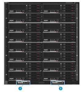
1. Make sure the enclosure has a minimum of one AE module present.
An enclosure supports a maximum of two AE modules, as shown in Figure 2.
Figure 2 AE module slots
|
1: Slot E1 |
2: Slot E2 |
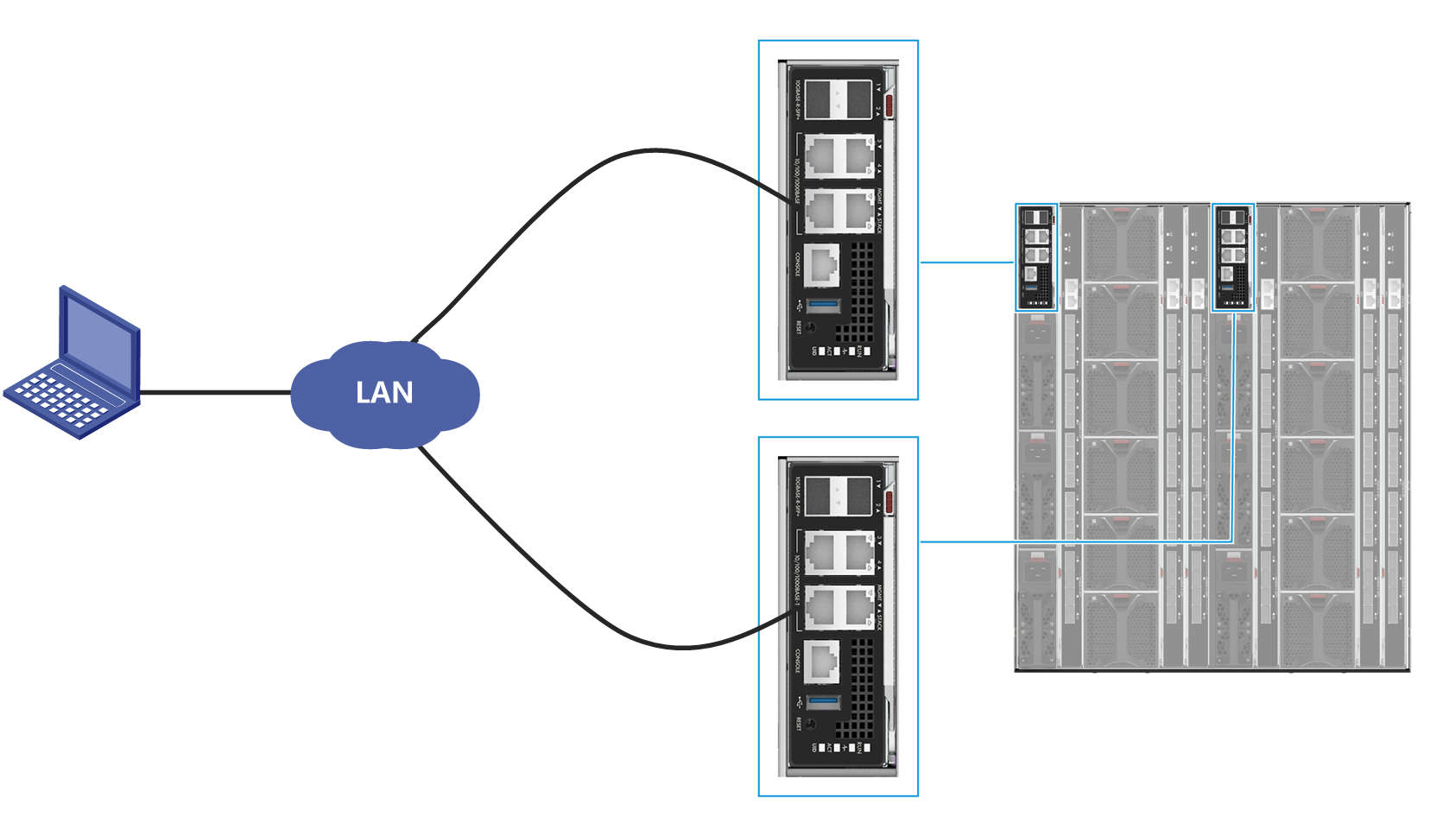
2. Connect the Ethernet port on the FIST client host to the MGMT port on the primary or standby OM module over the LAN, as shown in Figure 3.
Figure 3 Connecting to the OM module
3. On the FIST client, specify an IP address that resides on the same network segment as the FIST server. See Figure 2 for the default IP address of FIST server.
Obtain the FIST server IP address
|
|
IMPORTANT: After logging in to FIST running in an AE module by using the default IP address, change the FIST IP address to avoid IP address conflicts in the future. For how to change the FIST IP address, see "Configure the network settings." |
Table 2 shows the default settings for FIST running in an AE module.
|
Parameter |
FIST server location |
Parameter value |
|
Username |
N/A |
admin |
|
Password |
Password@_ |
|
|
FIST login IP address |
AE module slot E1 |
192.168.0.100/24 |
|
AE module slot E2 |
192.168.0.101/24 |
|
|
Non-AE environment |
System IP address of the device where FIST resides. |
FIST client requirements
Users can access FIST from a Web browser directly. See Table 3 for the supported Web browsers and recommended resolution.
|
Browser |
Resolution |
|
· Google Chrome 66.0 or later · Mozilla Firefox 60.0 or later |
1600 × 900 or higher |
Log in to FIST
1. Enter either of the following URLs in the address bar of the browser:
¡ http://FIST ip address:port , where port represents the HTTP port number used by FIST.
¡ https://FIST ip address:port , where port represents the HTTPS port number used by FIST.
You can configure the HTTP port and HTTPS port for FIST in the FIST service startup settings. For more information, see H3C Servers FIST Installation Guide.
Alternatively, you can access FIST locally from the server where FIST is installed. To do so, enter http://localhost:port or http://127.0.0.1 in the address bar of the Web browser.
2. On the FIST login page, enter the username and password of a FIST user.
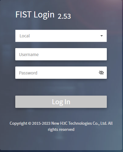
3. Click Log In.
The FIST Web interface opens, as shown in Figure 5. The FIST Web interface can be divided into two areas, as described in Table 4.
Figure 5 FIST Web interface
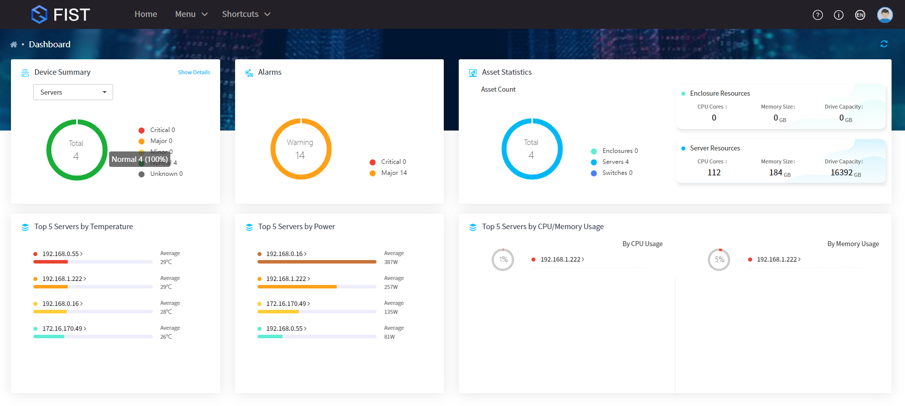
Table 4 FIST Web interface design description
|
Area |
Description |
|
Header section |
· · · · |
|
Work pane |
Displays operation information and function links. |
Access by shortcut
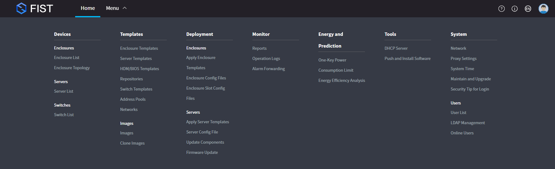
On the top navigation bar, you can use Shortcuts to access a specified menu directly. To add a
menu to Shortcuts, click Menu
and then click ![]() for the menu. To remove a
menu from Shortcuts, click Menu
and then click
for the menu. To remove a
menu from Shortcuts, click Menu
and then click ![]() for the menu. You can add a
maximum of 10 menus to Shortcuts.
for the menu. You can add a
maximum of 10 menus to Shortcuts.
Figure 6 Adding menus to shortcuts
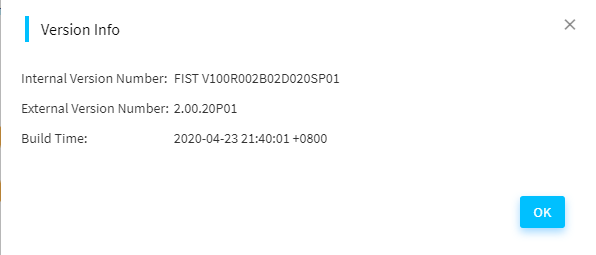
Check FIST version info
Click the Version Info
button ![]() in the top right corner to check the FIST
version information, as shown in Figure 7.
in the top right corner to check the FIST
version information, as shown in Figure 7.
Figure 7 FIST version information
Manage user settings
You can perform the following user management tasks in FIST:
· Manage the user accounts that can be used to log in to FIST.
· Configure a password complexity policy to enforce on the FIST users.
· Set the login rules to allow only logins matching specific requirements.
Manage users
Both local users and LDAP users are allowed to log in to FIST.
Manage local users
Add a user
About this task
You can add a user with an admin or guest role to FIST:
· admin—This role allows users to access all Web interface menus and execute all functional operations, such as user management, device management, OS installation, and component update.
· guest—This role allows users only to access all Web interface menus and change the password of its own.
FIST provides a default admin user account named admin.
Concurrent logins with the same admin user account is supported and each login is counted as a separate user. FIST supports a maximum of 30 concurrent online users.
Restrictions and guidelines
· FIST supports a maximum of 10 users including the default user admin.
· The name of a new user to be created cannot be System, which is used by the system.
Procedure
1. In the navigation pane, select Menu > System > User List.
The Users page displays all users.
Figure 8 Users page
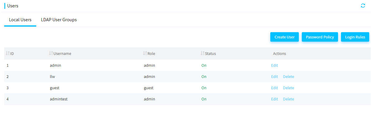
2. On the Local Users tab, click Create User.
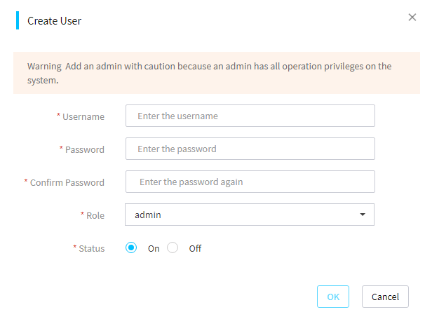
3. In the Create User dialog box, perform the following steps:
¡ Enter the username.
¡ Enter and confirm the password.
¡ Select a role, admin or guest.
¡ Select a status.
Figure 9 Create User dialog box
4. Click OK.
Edit a user
About this task
You can edit a user with an admin or guest role in FIST:
· An admin user can change the password, role, and status of all users (including default user admin).
· A guest user can change only its own password.
Restrictions and guidelines
· The password of users must meet the all requirements in the password policy.
· Editing an online user will forcibly log out the user. The new settings take effect at the next login of the user.
Procedures
To change the password of the default user:
1. In the navigation pane, select Menu > System > User List.
2. On the Local Users tab, click Edit in the Actions column for default user admin.
3. In the dialog box that opens, enter the current password, and then enter and confirm the new password.
4. Click OK.
To edit a non-default user:
1. In the navigation pane, select Menu > System > User List.
2. On the Local Users tab, click Edit in the Actions column for a non-default user.
3. In the dialog box that opens, perform the following steps:
¡ Select Change Password. Then, enter the current password, and enter and confirm the new password.
¡ Select a new role.
¡ Select a new status.
4. Click OK.
Delete a user
About this task
Perform this task to delete a non-default user.
· Only admin users can delete users.
· Default user admin cannot be deleted.
· Deleting an online user will forcibly log out the user (including the current user that performs the deletion operation).
Procedure
1. In the navigation pane, select Menu > System > User List.
2. On the Local Users tab, click Delete in the Actions column for the user you want to delete.
3. In the dialog box that opens, enter the password of the current login user.
4. Click OK.
Configure a password policy
About this task
Perform this task to enhance FIST access security by setting rules that the passwords of user accounts (including default user admin) must follow.
Procedure
1. In the navigation pane, select Menu > System > User List.
2. On the Local Users tab, click Password Policy.
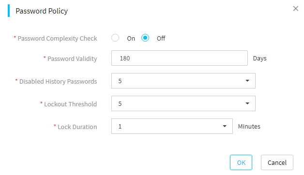
3. In the Password Policy dialog box, perform the following steps:
¡ Enable or disable the password complexity check.
¡ Set the password validity.
¡ Select the number of disabled history passwords.
¡ Select the password lockout threshold.
¡ Select the password lockout duration.
Figure 10 Password Policy dialog box
4. Click OK.
Parameters
· Password Complexity Check: Disable or enable password complexity check.
¡ If this feature is enabled, passwords must meet the following enhanced complexity requirements:
- 8 to 20 characters in length.
- Case sensitive. Valid characters are letters, digits, spaces, and the following special characters: ` ~ ! @ # $ % ^ & * ( ) _ + - = [ ] \ { } | ; ' : " , . / < > ?
- Must contain characters from at least two of the following categories: uppercase letters, lowercase letters, and digits.
- Must contain at least one space or special character.
- Must not be identical to the username or the reverse of the username.
¡ If this feature is disabled, passwords must meet the following basic complexity requirements:
- 1 to 20 characters in length.
- Case sensitive. Valid characters are letters, digits, spaces, and the following special characters: ` ~ ! @ # $ % ^ & * ( ) _ + - = [ ] \ { } | ; ' : " , . / < > ?
· Password Validity: Validity period of a password. When a password is about to expire, FIST prompts the user to change the password.
· Disabled History Passwords: Number of unique passwords that a user must create before a history password can be reused. For example, if you set the value to 2, a user must create two unique passwords before the user uses a history password.
· Lockout Threshold: Number of consecutive login failures that will cause a user account to be locked.
· Lock Duration: Amount of time before a locked account can be used again.
Manage login rules
About this task
Perform this task to configure login rules to control FIST login. If information of a user login matches a login rule, the login is allowed. If information of a user login does not match any login rule, the login is denied. By default, no login rules are configured, and all logins are allowed.
Restrictions and guidelines
Configure login rules with caution because a user is allowed to log in to FIST only when a matching login rule is found.
Procedures
To create a login rule:
1. In the navigation pane, select Menu > System > User List.
2. On the Local Users tab, click Login Rules.
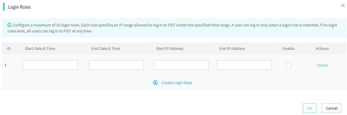
3. In the Login Rules dialog box that opens, click Create Login Rule, and then perform the following steps:
¡ Enter the start date & time and end time date & time of the time range during which users can log in to FIST.
¡ Enter the start IP address and end IP address.
¡ Check the box in the Enable column to activate the rule.
Figure 11 Login Rules dialog box
4. Click OK.
To edit login rules:
1. In the navigation pane, select Menu > System > User List.
2. On the Local Users tab, click Login Rules.
3. In the Login Rules dialog box that opens, edit the login rule settings.
4. Click OK.
To delete a login rule:
1. In the navigation pane, select Menu > System > User List.
2. On the Local Users tab, click Login Rules.
3. In the Login Rules dialog box that opens, click Delete in the Actions column for the login rule you want to delete.
4. Click OK.
Manage LDAP user groups
Users in the LDAP user groups that have been added to FIST can directly log in to FIST. An LDAP account cannot log in to FIST with pre-Windows 2000 logon name.
Add LDAP user groups
About this task
Perform this task to add LDAP user groups on an LDAP server to FIST. FIST supports a maximum of 10 user groups per LDAP server.
Before you add LDAP user groups to FIST, add the LDAP server hosting the LDAP user groups to FIST first. For more information, see "Manage LDAP."
Procedure
1. In the navigation pane, select Menu > System > User List.
2. Click the LDAP User Groups tab.
Figure 12 LDAP user groups tab
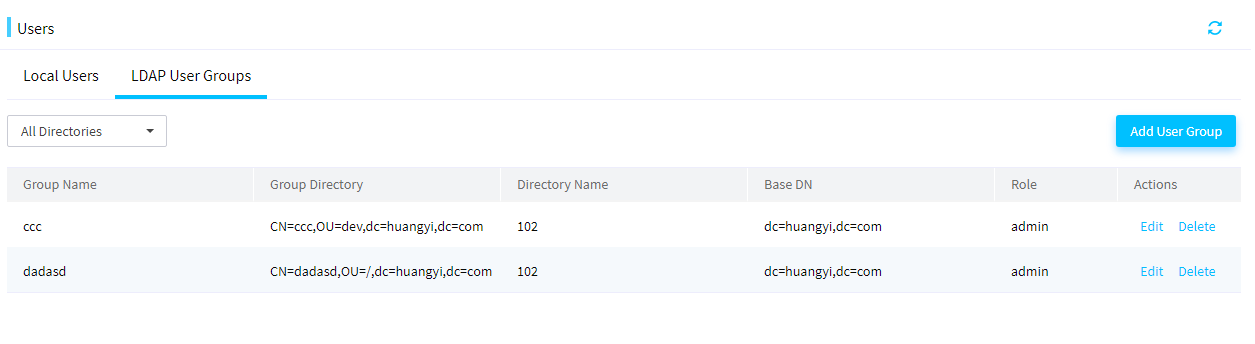
3. Click Add User Group. In the Add User Group dialog box that opens, configure the following parameters:
a. Select an LDAP server from the Directory list.
b. Select the directories of the LDAP user groups you want to add in the Group text box.
c. Select the role of the users in the user groups from the Role list.
Figure 13 Add user group dialog box
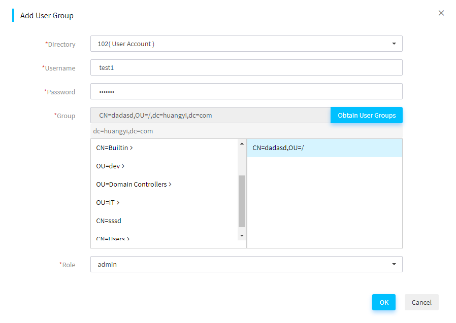
4. Click OK.
Edit LDAP user groups
1. In the navigation pane, select Menu > System > User List.
2. Click the LDAP User Groups tab.
3. Click the Edit icon in the Actions column for the target LDAP user group.
4. In the Edit User Group dialog box that opens, edit the user group settings and click OK.
Delete LDAP user groups
1. In the navigation pane, select Menu > System > User List.
2. Click the LDAP User Groups tab.
3. Click the Delete icon in the Actions column for the target LDAP user group.
4. In the confirmation dialog box that opens, click OK.
View online user information
Perform this task to view information about all online users.
Restrictions and guidelines
If a user exits FIST without clicking Log Out button ![]() on the FIST
Web interface, the user will not be removed from the online user list until the
timeout timer expires.
on the FIST
Web interface, the user will not be removed from the online user list until the
timeout timer expires.
Procedure
1. In the navigation pane, select Menu > System > Online Users.
The online user list displays all online users in FIST.
2. View information about the online users.
3. To kick out an online user, click the Kick Out link in the Actions column for the user. Only users with administrative privileges can kick out online users.
Figure 14 Online Users page
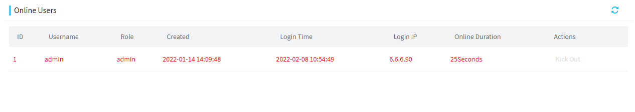
Parameters
· Username: Name of an online user.
· Role: Role of the user.
· Created: Time when the user was created.
· Login Time: Time when the user logged in to FIST most recently.
· Login IP: IP address used by the user to log in to FIST.
· Online Duration: Length of time elapsed since the user logged in to FIST.
Manage devices
FIST can manage both enclosures and servers.
Manage enclosures
From the Enclosure List menu, you can manage enclosures and the blade servers and other modules in the enclosures.
General restrictions and guidelines
FIST communicates with the OM module of an enclosure through HTTP to manage the enclosure. For FIST to manage an enclosure correctly, do not disable the HTTP service on the OM Web interface.
Manage enclosures
As shown in Figure 15, an AE module is shipped with FIST pre-installed. FIST provides centralized management of data center devices including the local enclosure where the AE module resides, remote enclosures, rack servers, and switches. You can access FIST on the AE module simply by connecting to the management port of the OM module, which is connected to the AE module by default within the enclosure.
Figure 15 FIST management enclosure network diagram
Add an enclosure
About this task
Perform this task to add an enclosure to FIST. If an enclosure to be added has enclosures cascaded, FIST will automatically add the cascaded enclosures.
If FIST is running in an AE module, the enclosure where the AE module resides will be added to FIST automatically and cannot be deleted.
Adding an enclosure to FIST automatically adds all blade servers installed in the enclosure to FIST. You can view the blade servers on the Menu > Devices > Server List page.
Restrictions and guidelines
If the OM management address of the enclosure to be added is on a different subnet than FIST, you must configure the network settings to enable FIST to communicate with the enclosure. For more information, see "Configure the network settings."
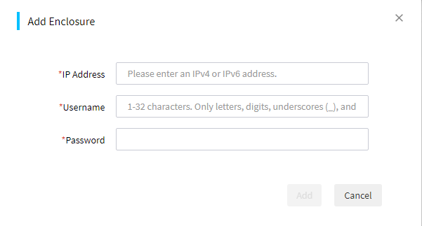
Procedure
1. In the navigation pane, select Menu > Devices > Enclosure List.
2. Click Add Enclosure.
3. In the dialog box that opens, configure the required parameters, and then click OK.
Figure 16 Adding an enclosure
Delete an enclosure
About this task
Perform this task to delete an enclosure.
Restrictions and guidelines
If FIST is running in an AE module, the enclosure where the AE module resides cannot be deleted.
Procedure
1. In the navigation pane, select Menu > Devices > Enclosure List.
2. Click Delete in the Actions column for the enclosure to be deleted.
3. In the confirmation dialog box that opens, click OK.
View enclosure information
About this task
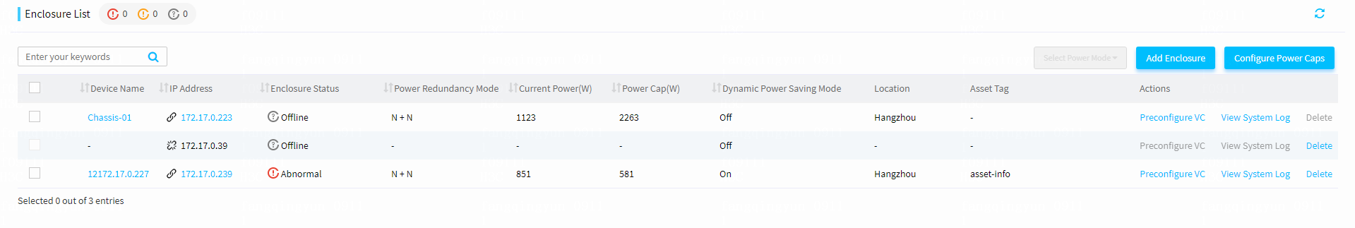
Perform this task to access the enclosure list page to view information about enclosures managed by FIST. From the page, you can also drill down to view the detailed information of individual enclosures.
Procedure
1. In the navigation pane, select Menu > Devices > Enclosure List. The Enclosure List page displays information about all enclosures.
Figure 17 Enclosure list page
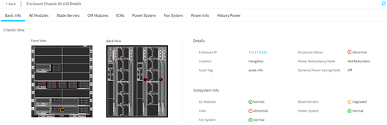
2. Click the name of an enclosure to open the enclosure details page.
Figure 18 Enclosure Details
Configure power caps for enclosures
About this task
Perform this task to set the power caps for enclosures, either statically or dynamically depending on the configuration method you select. The power cap set for an enclosure determines the maximum amount of power that can be consumed by the enclosure and all the devices installed in it.
Supported power cap configuration methods are:
· Auto—Configure FIST to dynamically allocate power caps to selected enclosures in bulk. In this mode, select the target enclosures, set the total power cap value that can be allocated to these enclosures, and click OK. Then, FIST automatically allocates a power cap to each enclosure in proportion to the enclosure's share of the total power consumed by all the selected enclosures. That is, the higher the current power of an enclosure, the higher the power cap allocated to it. If the power cap calculated for an enclosure exceeds the limit (18000 W), the enclosure's power cap will be set to 18000 W.
· Manual—Manually specify the power caps for individual enclosures.
Restrictions and guidelines
· The power cap of an enclosure is in the range of 2500 W to 18000 W.
· To dynamically set the power caps for N enclosures from a total available power cap value, specify the total aggregate power cap in the range of 2500 W*N to 18000W*N.
Procedure
1. In the navigation pane, select Menu > Devices > Enclosure List.
2. Click Configure Power Caps.
3. Select a configuration method, Manual or Auto.
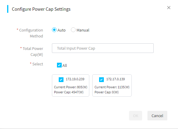
4. To have FIST dynamically allocate power caps to enclosures:
a. Select Auto for Configuration Method.
b. Select the target enclosures. By default, all enclosures are selected.
c. In the Total Power Cap (W) field, specify the total power cap value that can be allocated to the selected enclosures.
Figure 19 Configuring FIST to dynamically allocate power caps to selected enclosures
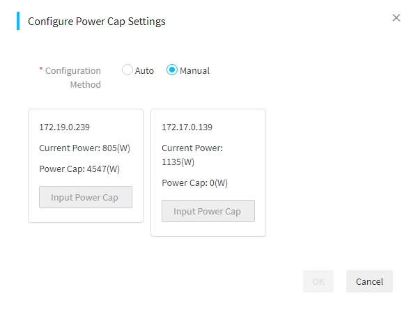
5. To set power caps for individual enclosures manually:
a. Select Manual for Configuration Method.
b. Set the power cap value for each enclosure.
Figure 20 Manually setting the power caps for enclosures
6. Click OK.
Set the power mode for enclosures
About this task
Perform this task to configure the power settings for an enclosure.
The power supply system of an enclosure can contain up to six hot-swappable power supplies. Install power supplies and configure the power redundancy mode according to the enclosure's power requirements, which vary depending on the number and type of devices installed in the enclosure.
FIST supports the following power management features:
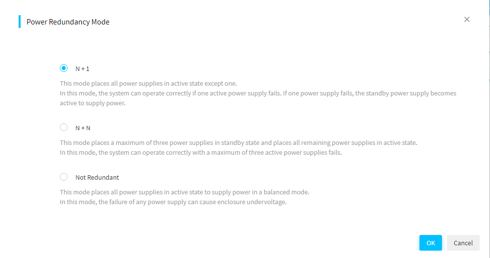
· Power redundancy mode—Protects an enclosure from power supply failures.
FIST supports both the N+1 and N+N redundancy modes. In the event of one or more power supply failures, the redundant power supplies take over the load to prevent the system from powering off. The system powers off only when the surviving power supplies do not have enough power to meet the system's power requirements. If no redundant power supply is available (as is the case with the No Redundancy mode), the system might power off when one power supply fails.
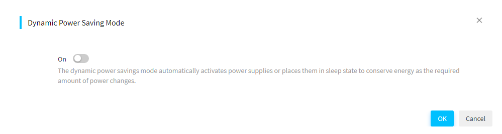
· Dynamic power saving mode—Automatically places unused power supplies in standby mode to increase enclosure power supply efficiency, thereby minimizing enclosure power consumption during lower power demand. Increased power demands automatically return standby power supplies to full performance.
For example, assume that an enclosure has six power supplies installed, is configured to work in N+1 power redundancy mode, and requires two active power supplies to supply the current power.
¡ If the dynamic power saving mode is enabled, only three power supplies share in delivering the enclosure power load, with one being the redundant power supply. The remaining three power supplies will be placed in standby mode.
¡ If the dynamic power saving mode is disabled, all of the six power supplies share the power load.
Restrictions and guidelines
· Make sure all power supplies installed in the enclosure are of the same model.
Table 5 provides information about supported power supplies.
Supported power supplies
|
Type |
Model |
Rated input voltage range |
Maximum rated output power |
|
3000 W AC power supply |
PSR3000-12A |
100 VAC to 240 VAC |
3000 W |
· When setting the power redundancy mode for an enclosure, make sure the enclosure has the correct number of power supplies installed in the correct locations.
Table 6 shows the recommended power settings for an enclosure with 3000 W AC power supplies. If the number of power supplies exceeds the recommended number, enable the dynamic power saving mode to reduce power consumption.
Table 6 Recommended power settings for an enclosure with 3000 W AC power supplies
|
Max power that can be supplied |
Power redundancy mode |
Number of power supplies installed |
Recommended power supply bays |
|
3000 W |
No Redundancy |
1 |
PSU_1 |
|
6000 W |
No Redundancy |
2 |
PSU_1, PSU_2 |
|
9000 W |
No Redundancy |
3 |
PSU_1, PSU_2, PSU_3 |
|
12000 W |
No redundancy |
4 |
PSU_1, PSU_2, PSU_3, PSU_4 |
|
15000 W |
No Redundancy |
5 |
PSU_1, PSU_2, PSU_3, PSU_4, PSU_5 |
|
18000 W |
No Redundancy |
6 |
PSU_1, PSU_2, PSU_3, PSU_4, PSU_5, PSU_6 |
|
3000 W |
1+1 redundancy |
2 |
PSU_1, PSU_2 |
|
6000 W |
2+1 redundancy |
3 |
PSU_1, PSU_2, PSU_3 |
|
9000 W |
3+1 redundancy |
4 |
PSU_1, PSU_2, PSU_3, PSU_4 |
|
12000 W |
4+1 redundancy |
5 |
PSU_1, PSU_2, PSU_3, PSU_4, PSU_5 |
|
15000 W |
5+1 redundancy |
6 |
PSU_1, PSU_2, PSU_3, PSU_4, PSU_5, PSU_6 |
|
6000 W |
2+2 redundancy |
4 |
PSU_1, PSU_2, PSU_3, PSU_4 |
|
9000 W |
3+3 redundancy |
6 |
PSU_1, PSU_2, PSU_3, PSU_4, PSU_5, PSU_6 |
Procedure
1. In the navigation pane, select Menu > Devices > Enclosure List.
2. To set the power redundancy mode for an enclosure, select the enclosure, click Select Power Mode, and then select Power Redundancy Mode from the menu. In the dialog box that opens, select a power redundancy mode as needed, and then click OK.
Figure 21 Setting power redundancy mode
3. To enable or disable the dynamic power saving mode for an enclosure, select the enclosure, click Select Power Mode, and then select Dynamic Power Saving Mode from the menu. In the dialog box that opens, enable or disable the dynamic power saving mode as needed, and then click OK.
Figure 22 Enabling or disabling the dynamic power saving mode
Manage OM modules
About this task
As the management core of an enclosure, the OM module is interconnected with all other modules inside the enclosure through the enclosure's backplane to provide centralized management and monitoring.
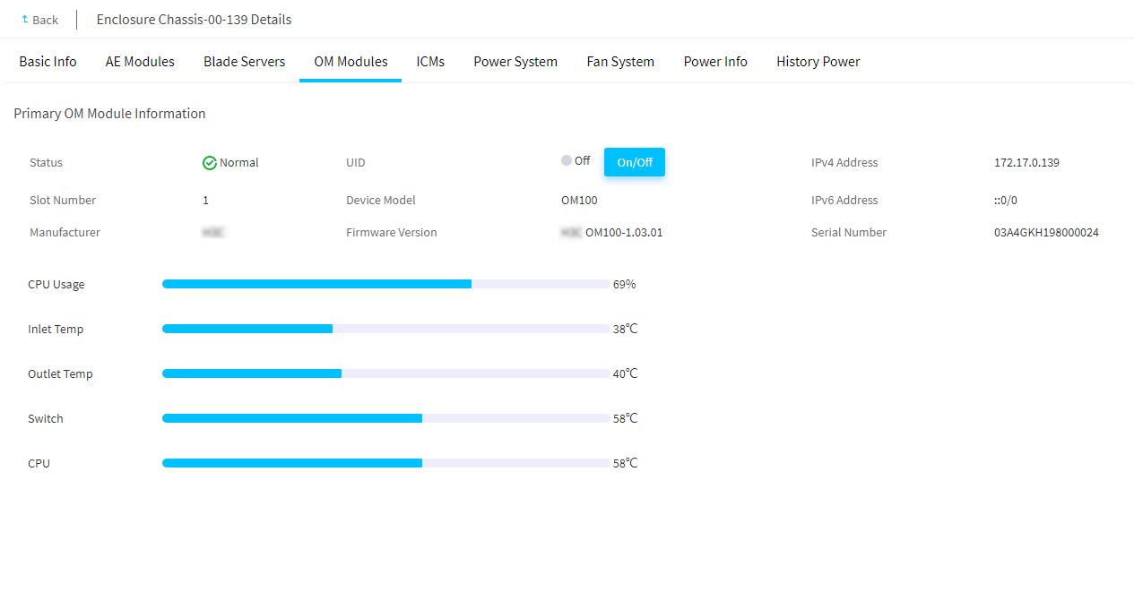
The OM Modules tab of an enclosure details page displays information about the primary and secondary OM modules in the enclosure. From the tab, you can turn on or turn off the UID LED for the OM modules. Turning on the UID LED helps locate the enclosure, especially in a high-density equipment room.
Procedure
1. In the navigation pane, select Menu > Devices > Enclosure List.
2. Click the name of an enclosure.
3. Click the OM Modules tab.
The tab displays information about the primary and secondary OM modules in the enclosure.
4. (Optional.) Turn on or off the UID LED as needed.
Figure 23 Viewing the OM module information of an enclosure
Manage AE modules
From the AE Modules tab of an enclosure details page, you can perform the following tasks:
· View basic and detailed information about each AE module in the enclosure.
· Turn on or turn off the UID LED for AE modules.
· Manage the virtual power for AE modules. For example, you can power on one or more selected AE modules.
· Launch a remote console to an AE module.
For the AE module where FIST resides, you can only view its basic information. Other functions are not supported.
Access the AE module list page
About this task
Perform this task to access the AE module list page of an enclosure.
Procedure
1. In the navigation pane, select Menu > Devices > Enclosure List.
2. Click the name of an enclosure.
3. Click the AE Modules tab.
The tab lists all AE modules in the enclosure.
Figure 24 AE module list page of an enclosure
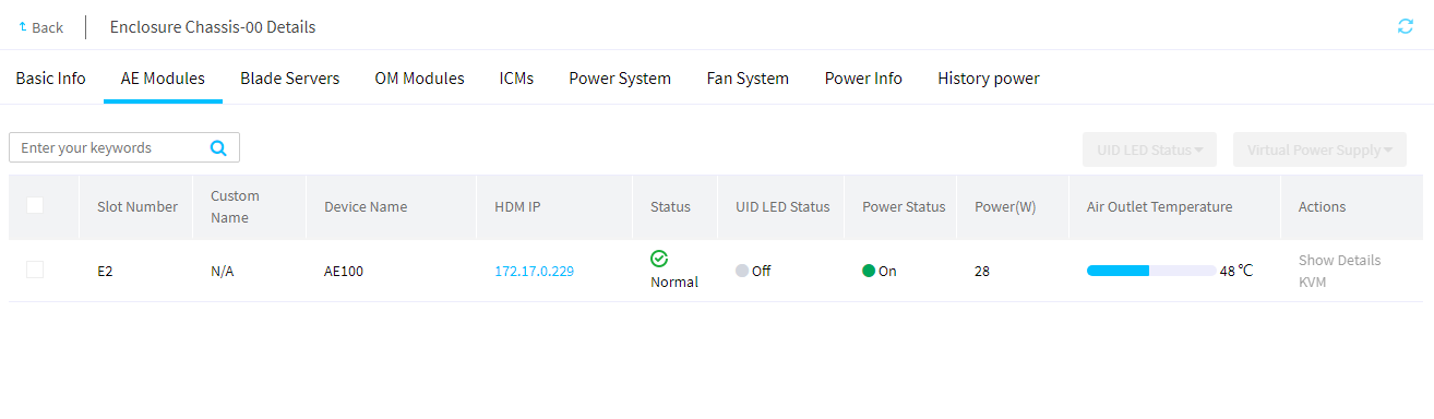
4. To change the UID LED state for one or more AE modules, select the AE modules, and then select On or Off from the UID LED Status list in the upper right corner.
5. To change the virtual power supply state for one or more AE modules, select the AE modules, and select a power option from the Virtual Power Supply list in the upper right corner. Then, click OK in the dialog box that opens.
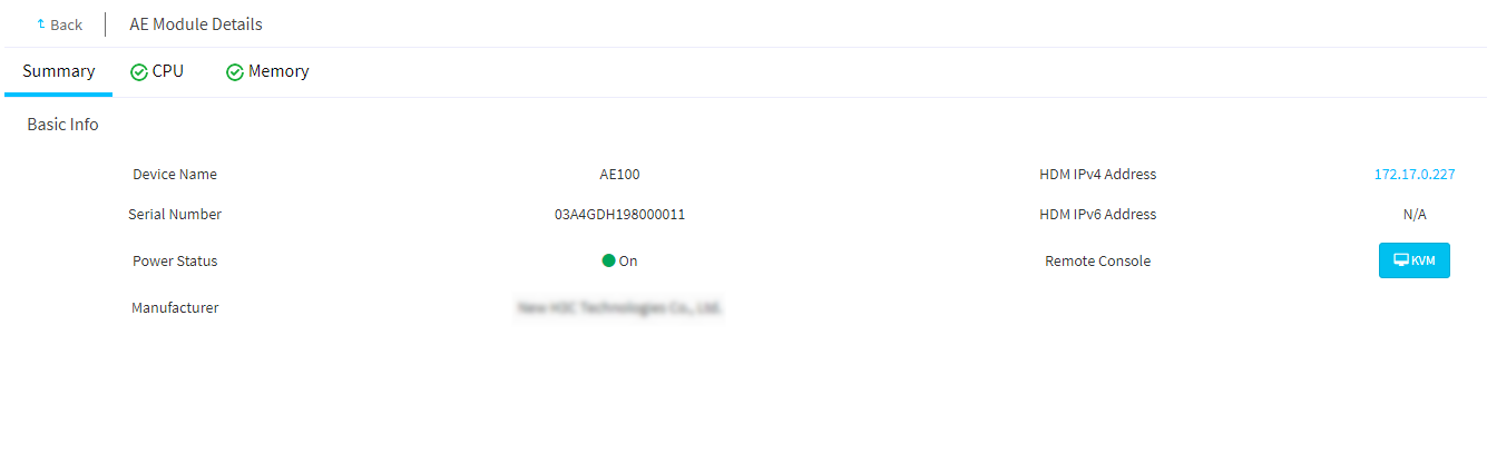
View detailed information about an AE module
About this task
Perform this task to access the details page of an AE module. The page displays information about the AE module on separate tabs, including Basic Info, CPU, and Memory.
Restrictions and guidelines
You cannot view detailed information about the local AE module where FIST resides.
Procedure
1. In the navigation pane, select Menu > Devices > Enclosure List.
2. Click the name of an enclosure.
3. Click the AE Modules tab.
The AE module list page opens.
4. Click Show Details in the Actions column for the AE module whose detailed information you want to view.
The AE module details page opens, displaying the Summary tab by default.
5. To view the CPU information of the AE module, click the CPU tab.
6. To view the memory information of the AE module, click the Memory tab.
Figure 25 AE module details page
Launch a remote console
About this task
Perform this task to manage an AE module from the KVM remote console.
Prerequisites
Before you can launch the KVM remote console for an AE module from FIST, verify that the KVM service is enabled on the AE module. If the KVM service is not enabled, enable the KVM service on the Security > Access services page of the AE module's HDM Web interface.
Restrictions and guidelines
This function is not available for the local AE module where FIST resides.
Procedure
1. In the navigation pane, select Menu > Devices > Enclosure List.
2. Click the name of an enclosure.
3. Click the AE Modules tab.
4. Click the KVM link in the Actions column for the target AE module.
5. Download the .jnlp file when prompted, and then run the file to launch the remote console window.
Manage blade servers
The blade servers in an enclosure provide compute and storage services.
From the Blade Servers tab of an enclosure details page, you can perform the following tasks:
· View basic and detailed information about the blade servers in the enclosure.
· Turn on or turn off the UID LED for blade servers.
· Manage the virtual power for blade servers. For example, you can power on or power off the blade servers.
· Set the one time boot options for blade servers
· Launch a remote console to a blade server.
Access the blade server list page of an enclosure
About this task
Perform this task to open the blade server list page of an enclosure.
Procedure
1. In the navigation pane, select Menu > Devices > Enclosure List.
2. Click the name of an enclosure.
3. Click the Blade Servers tab.
The tab lists all blade servers in the enclosure.
Figure 26 Blade Server tab of an enclosure
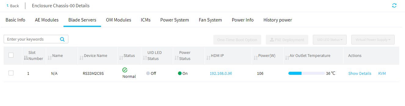
4. To change the UID LED state for one or more blade servers, select the blade servers, and then select On or Off from the UID LED Status list.
5. To change the virtual power supply state for one or more blade servers, select the blade servers, and select a power option from the Virtual Power Supply list. Then, click OK in the dialog box that opens.
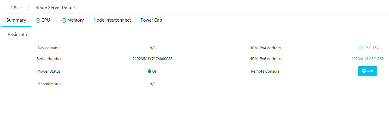
6. To view detailed information about a blade server, click the Details link in the Actions column for the server.
The page displays the summary information of the blade server by default. Click the Summary, CPU, Memory, and Node Interconnect tabs to view the CPU, memory, and mezzanine card information of the server as needed.
Figure 27 Blade server details page
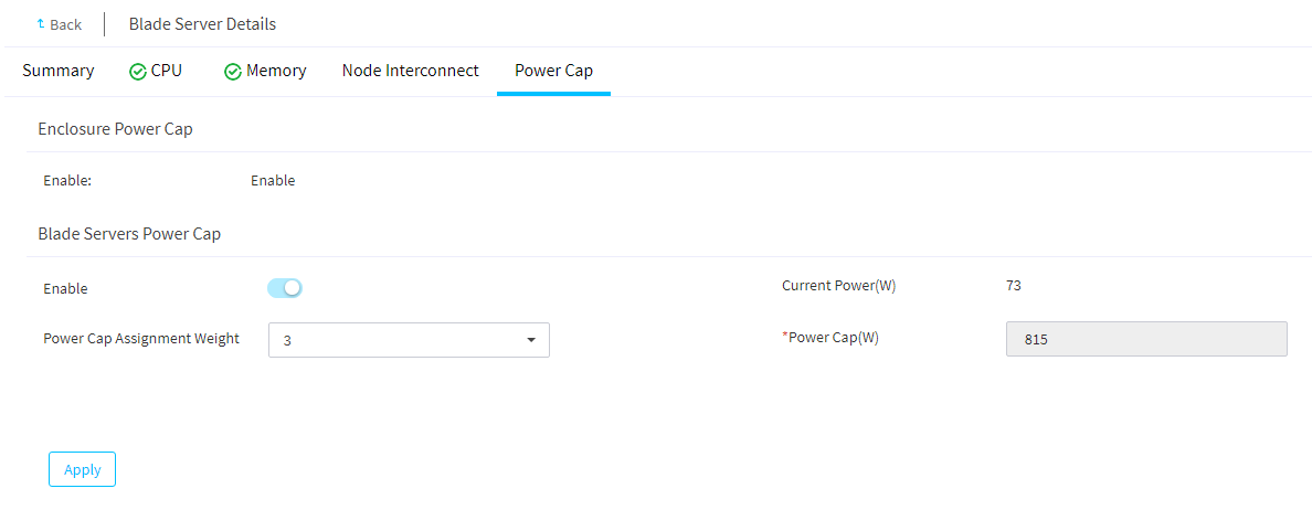
Set the power cap for a blade server
About this task
Perform this task to set the power cap or power cap assignment weight for a blade server.
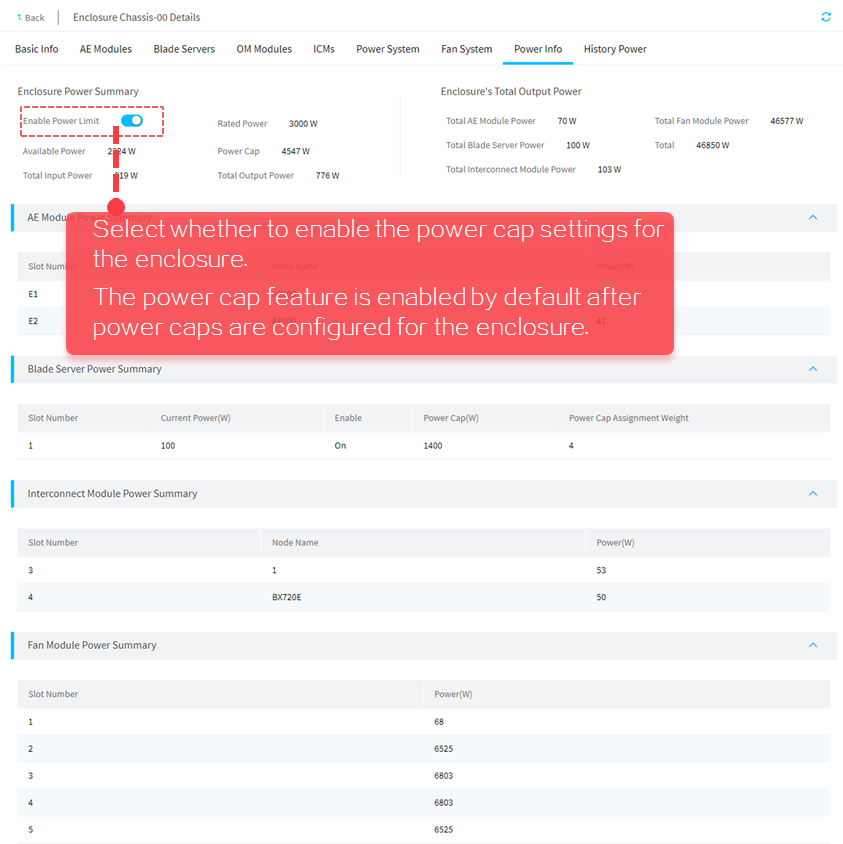
To set the power cap for a blade server, you must first disable the power cap feature for the enclosure where the server resides. For more information, see "View power information."
If power cap is enabled for an enclosure, you can set the power cap assignment weight for individual blade servers installed in the enclosure. A higher weight indicates that the blade server can get a higher power cap value. The default power cap assignment weight varies by the blade server type:
· For a 2-processor compute blade server, the default value is 2.
· For a 2-processor storage blade server, the default value is 3.
· For a 4-processor compute blade server, the default value is 4.
Procedure
1. In the navigation pane, select Menu > Devices > Enclosure List.
2. Click the name of an enclosure, and then click the Blade Servers tab.
3. Click Show Details in the Actions column for the blade server for which you want to set the power cap.
4. Click the Power Cap tab.
5. Set the power cap assignment weight or power cap value for the blade server:
¡ If power cap is enabled for the enclosure, set the power cap assignment weight for the blade server.
¡ If power cap is disabled for the enclosure, enable power cap for the blade server and set the power cap value for the blade server.
6. Click Apply.
Figure 28 Setting the power cap for an enclosure
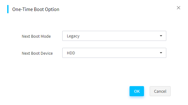
Configure boot option for the next reboot
About this task
Perform this task to specify the one-time boot mode and boot device for a server to use at the next reboot.
Procedure
1. In the navigation pane, select Menu > Devices > Enclosure List.
2. Click the name of an enclosure.
3. Click the Blade Servers tab.
4. Select the target servers, and then click One-Time Boot Option.
5. Configure the following parameters as needed:
¡ Next Boot Mode: Select the boot mode for the next reboot. Options include Legacy and UEFI (the default). To use the boot mode set in BIOS for the next reboot, leave this field empty.
¡ Next Boot Device: Select the boot device for the next reboot. Options include HDD, PXE, BIOS, and CD/DVD. To use the BIOS settings at the next reboot, leave this field empty.
6. Click OK.
Figure 29 Setting the one-time boot option
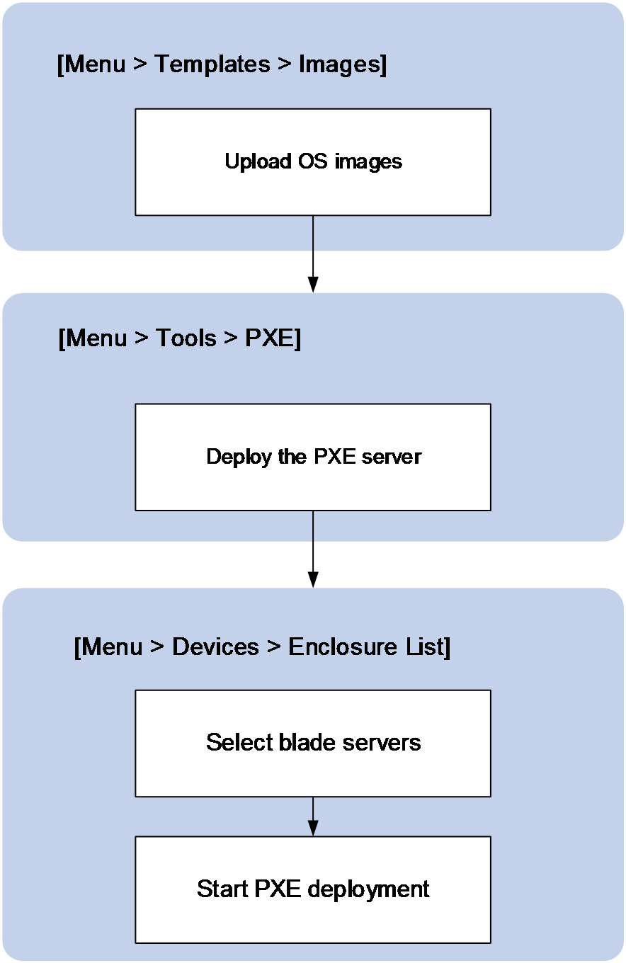
Install operating systems by using PXE
About this task
Perform this task to bulk install operating systems on blade servers by using PXE.
Before PXE deployment, upload the OS image to the Menu > Templates > Images list and enable the PXE server. For more information, see "Manage images" and "Configure PXE deployment."
Figure 30 shows the PXE deployment procedure.
Figure 30 PXE deployment procedure
Restrictions and guidelines
Make sure the IP addresses in the DHCP IP pool do not conflict with existing IP addresses on the network.
Make sure the BIOS boot mode used during the PXE installation of the operating system is the same as the BIOS boot mode used for subsequent access to the operating system. Otherwise subsequent access to the operating system might fail.
The default root password for the Linux OS installed by this feature is 123456.
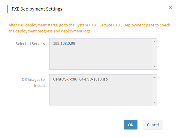
Procedure
1. In the navigation pane, select Menu > Devices > Enclosure List.
2. Click the name of an enclosure.
3. Click the Blade Servers tab.
4. Select the target servers, and then click PXE Deployment.
5. Configure the PXE installation parameters and complete the OS installation on the selected servers.
Figure 31 Install operating systems by using PXE
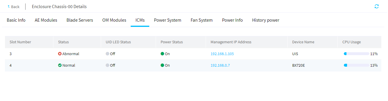
View interconnect modules
About this task
Perform this task to view the interconnect modules in an enclosure.
Interconnect modules connect devices within an enclosure so they can communicate with each other. They also provide external data interfaces for connecting to external devices.
Procedure
1. In the navigation pane, select Menu > Devices > Enclosure List.
2. Click the name of an enclosure.
3. Click the ICMs tab.
Figure 32 ICMs tab
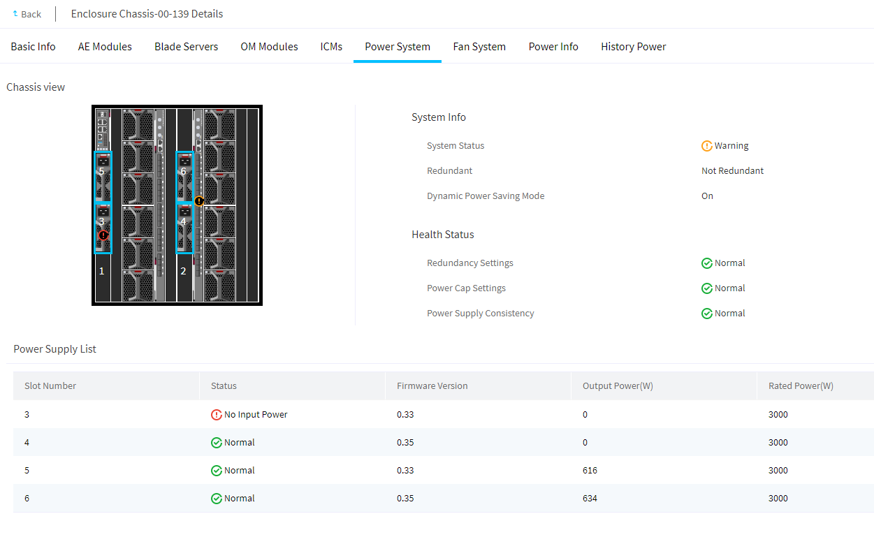
View power system information
About this task
Perform this task to view the power supply information of an enclosure, including the power system information, health status, and power supply list.
Procedure
1. In the navigation pane, select Menu > Devices > Enclosure List.
2. Click the name of an enclosure.
3. Click the Power System tab.
The tab displays information about power supplies in the enclosure.
Figure 33 Power System tab
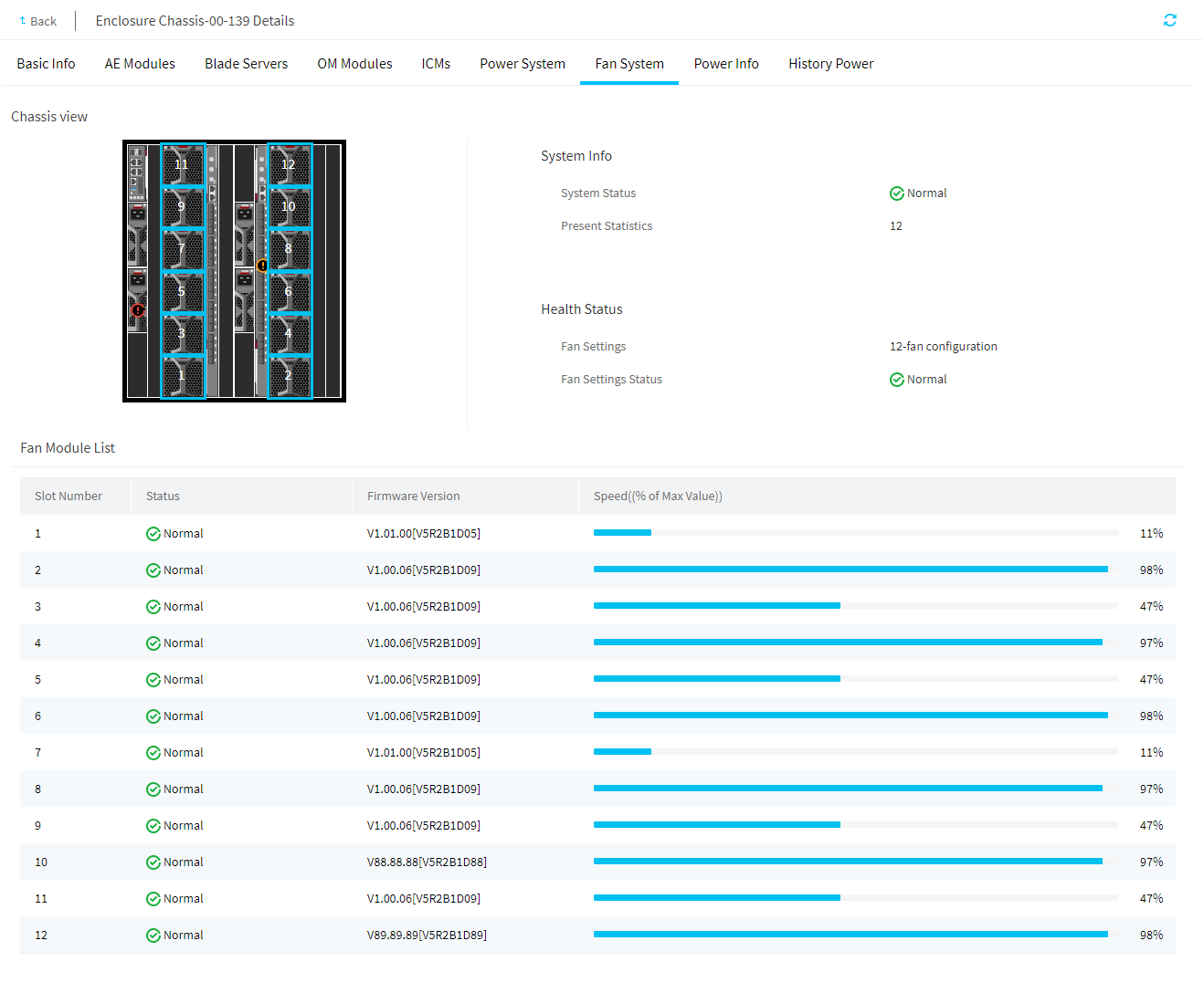
View fan system information
About this task
Perform this task to view basic information about fans, including the fan system information, health status, and fan module list.
The fan system supports a maximum of 12 fans in an enclosure, which provide N+1 redundancy. If one fan fails, the remaining fans keep running at the full speed to ensure heat dissipation, and the fan system remains in normal state.
The requirement on fan configuration depends on the installation situation of blade servers in an enclosure. When you install blade servers in an enclosure, follow these restrictions and guidelines:
· Install blade servers in the enclosure from left to right and from bottom to top.
· If both half-width and full-width blade servers are to be installed, install half-width blade servers first.
Based on the installation situation of blade servers in an enclosure, use one of the following fan configurations:
· 8-fan configuration: If area 3 of the enclosure does not have blade servers installed, you must install a minimum of 8 fans in the enclosure. Make sure fan bays 1 through 8 are installed with fans.
· 12-fan configuration: If area 3 of the enclosure has blade servers installed, you must install 12 fans in the enclosure.
Figure 34 Blade server installation areas
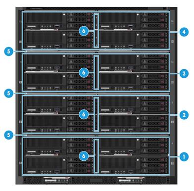
|
(1) to (4) Blade server installation areas |
|
(5) Fixed device bay shelf |
|
(6) Removable device bay divider |
Figure 35 Fan bays
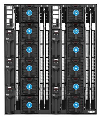
|
(1) to (12) Fan bays |
Procedure
1. In the navigation pane, select Menu > Devices > Enclosure List.
2. Click the name of an enclosure.
3. Click the Fan System tab.
The tab displays information about fans in the enclosure.
Figure 36 Fan System tab
View power information
Perform this task to view the enclosure's power summary information, the enclosure's total output power information, and the power summary information of AE modules, blade servers, interconnect modules, and fans.
Procedure
1. In the navigation pane, select Menu > Devices > Enclosure List.
2. Click the name of an enclosure.
3. Click the Power Info tab.
The tab displays information about power information of the enclosure.
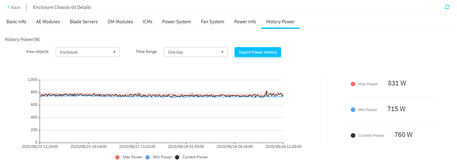
View power history
About this task
Perform this task to view and export power history data of an enclosure or blade servers in the enclosure. You can view the last week's data aggregated at 1-hour intervals, or view the last day's data aggregated at 5-minute intervals.
Procedure
1. In the navigation pane, select Menu > Devices > Enclosure List.
2. Click the name of an enclosure.
3. Click the History Power tab.
The tab page displays a power history chart and power history statistics of the enclosure.
4. To display power history statistics of an object within a time range, select the object from the View Objects list and the time range from the Time Range list.
5. Hover over a point on the power history chart to view the power statistics of the corresponding time.
6. To export power history statistics, click Export Power History.
Figure 38 Power History tab
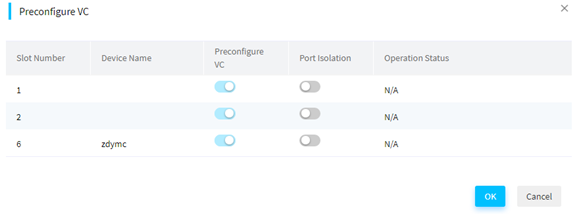
Preconfigure VC
About this task
Restrictions and guidelines
This feature becomes unavailable if an interconnect module is configured with IRF.
To use the VC preconfiguration function, make sure the firmware version of the OM module is between UN_BLADE-OM-1.02.08 and 1.02.12.
Before VC preconfiguration, make sure the remaining storage space of the OM module and interconnect module is enough to avoid configuration failure.
Procedure
1. In the navigation pane, select Menu > Enclosures > Enclosure List.
2. Click Preconfigure VC in the Actions column.
3. In the dialog box that opens as shown in Figure 39, preconfigure VC and click OK.
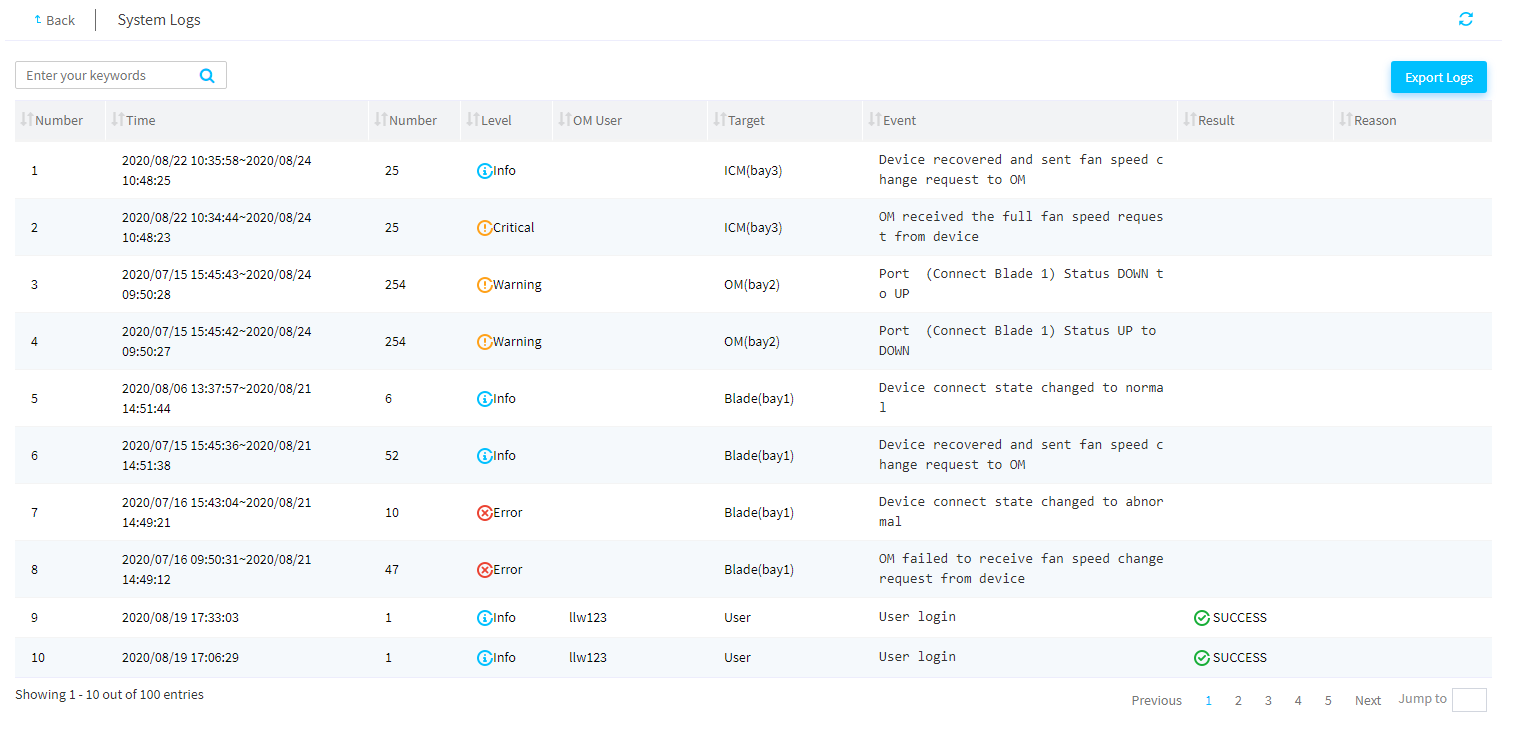
View system logs
About this task
Perform this task to view and export system logs of an enclosure. System logs records all events that occurred on an enclosure.
Restrictions and guidelines
Restarting an OM module or enclosure will clear all system logs of the OM module or enclosure.
The system can save a maximum of 100 system logs. When this limit is reached, the oldest system log is deleted.
You can export system logs within 31 days to a local file. Exported system logs will be removed from the System Logs page.
To view and export system logs of the past year, you must log in to the OM Web interface.
Procedure
1. In the navigation pane, select Menu > Devices > Enclosure List.
2. Click View System Log in the Actions column for an enclosure.
The System Logs page opens.
3. To export the system logs, click Export Logs tab.
The system exports system logs of the past 31 days to a local file named sys_log.
Figure 40 Viewing the system logs of an enclosure
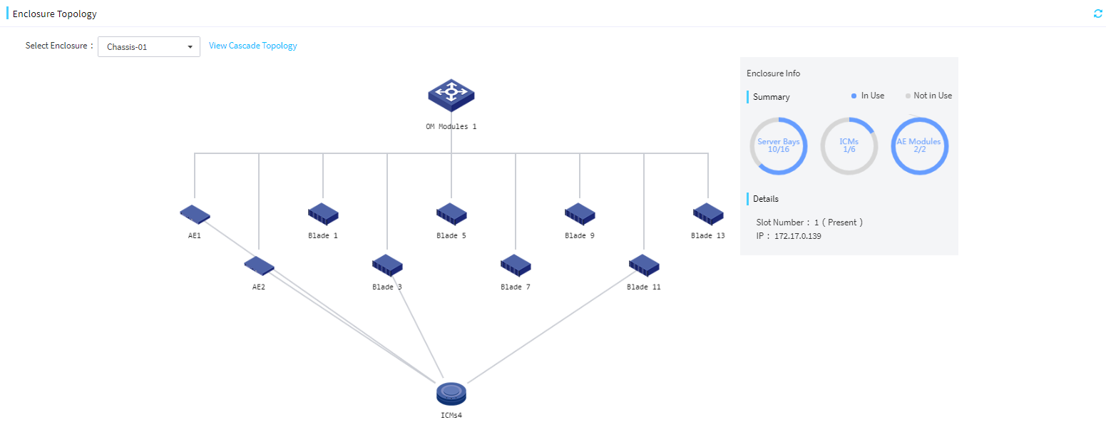
View the enclosure topology
About this task
Perform this task to view the internal topology and the cascade topology (if any) of an enclosure.
· Internal topology—Displays the blade servers, OM modules, mezzanine cards, interconnect modules, and AE modules as well as their interconnections in the enclosure. From the enclosure topology page, you can drill down to view detailed information about a blade server.
· Cascade topology—Displays enclosures cascaded to the enclosure.
Restrictions and guidelines
FIST can display the topology only for online enclosures. If an enclosure is offline or somehow cannot be connected, an offline tag is appended to the enclosure name and you cannot view the topology of the enclosure.
Procedure
1. In the navigation pane, select Menu > Enclosures > Enclosure Topology.
2. From the Select Enclosure list, select the name of an enclosure to open its topology.
Figure 41 Enclosure topology
3. Click a blade server in the topology to open the Enclosure Network Topology Blade Server Details page for the server. The page displays the connections between interconnect modules and mezzanine cards on the server.
Figure 42 Enclosure Network Topology Blade Server Details page
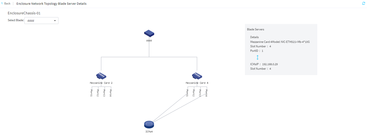
4. To view information about another blade server in the enclosure, select the server from the Select Blade list.
5. To view the cascade topology of the enclosure, click Back. On the Enclosure Topology page that opens, click View Cascade Topology next to the name of the enclosure. If View Cascade Topology is greyed out, it indicates that no enclosures are cascaded to the enclosure.
The Enclosure Cascade Topology page displays the enclosures cascaded to the enclosure. You can click an enclosure on this page to view its details, including the enclosure name, cascade number, enclosure IP address, and enclosure status.
Figure 43 Enclosure Cascade Topology page for an enclosure
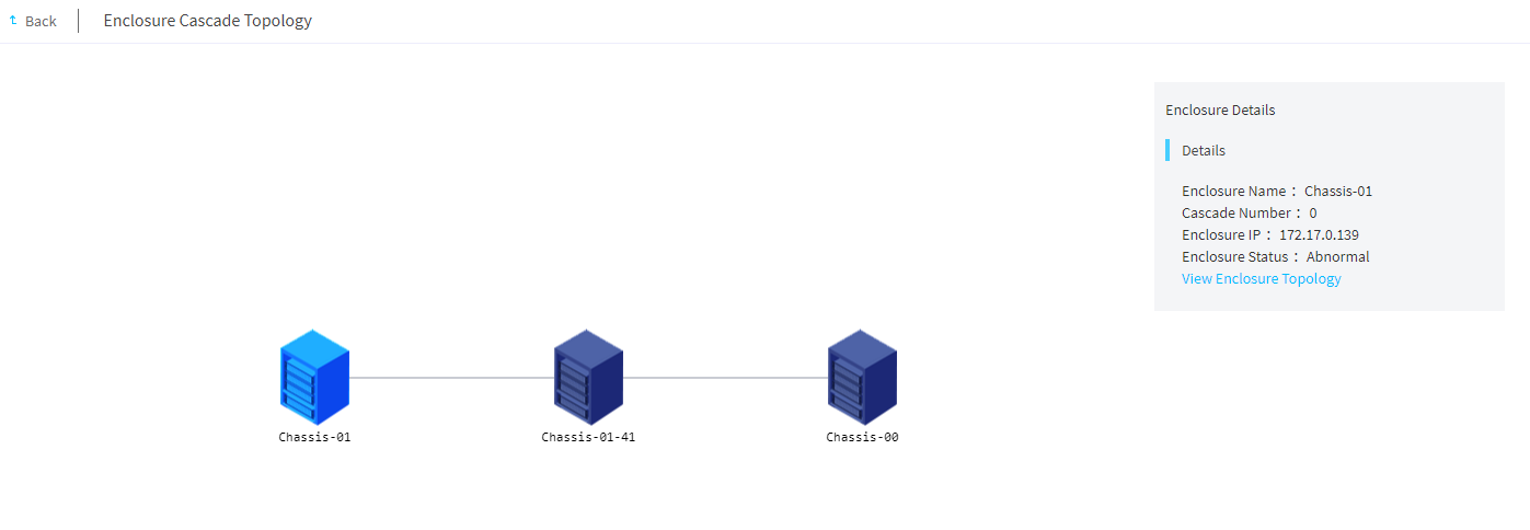
6. To return to the internal topology of the enclosure selected on this page, click View Enclosure Topology. This link is unavailable if the selected enclosure is not managed by FIST or is offline.
7. To return to the internal topology of the enclosure selected from the Select Enclosure list, click Back.
Manage servers
FIST can manage servers through HDM or FIST SMS installed on the servers.
With FIST, you can perform the following server management tasks:
· Add servers to FIST, edit server management settings in FIST, and delete servers from FIST.
· Launch a remote console to a managed server.
· View information about servers managed by FIST.
· Manage servers remotely from FIST. For example, you can power on or power off serves, turn on or off UID LEDs for servers.
General restrictions and guidelines
· If a device is managed by FIST, do not modify the device port number. If the port number is modified, you must add the device again or wait for a maximum of half an hour for the device to restore its port number automatically.
· When adding a FIST SMS server node to FIST, make sure the following requirements are met:
¡ The firewall is disabled on the server or port 12580 is added to the whitelist in the firewall.
¡ SELinux is disabled.
¡ The server has HDM installed and does not have an ongoing upgrade process.
¡ The server node can connect to the FIST server through the IP address of the operating system.
· When adding an HDM server node to FIST, make sure the following requirements are met:
¡ The FIST server can connect to the HDM dedicated network port or shared network port on the HDM server node.
¡ The access service ports used for communications with FIST are available on the HDM server node. Table 7 lists the default port numbers used by the access services.
To avoid IPMI communication failures, do not change the default ports used by the IPMI service.
Table 7 Default port numbers used by the access services
|
Service |
Default insecure port |
Default secure port |
|
CD-Media |
5120 |
5124 |
|
IPMI |
623 |
664 |
|
KVM |
7578 |
7582 |
|
SNMP Trap |
162 |
NA |
|
Web |
80 |
443 |
Add, edit, or delete servers
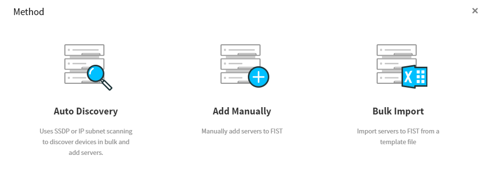
You can add servers to FIST manually, through auto discovery, or through bulk import. For servers added to FIST, you can edit their settings or delete them as needed.
Manually add a server to FIST
About this task
Perform this task to manually add HDM or FIST SMS server nodes to FIST.
Procedure
1. In the navigation pane, select Menu > Devices > Server List.
2. Click Add.
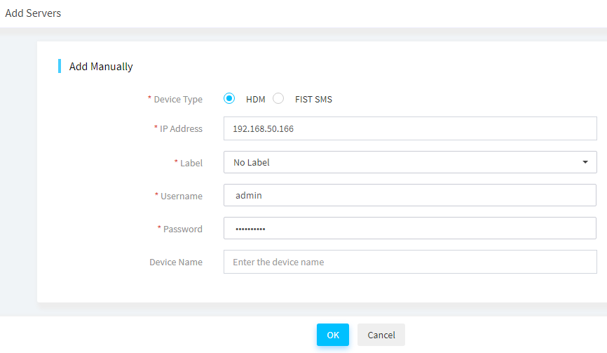
3. In the Method dialog box, select Add Manually.
4. Enter the device information and select a label:
¡ To add an HDM server node, select HDM for Device Type.
Specify the HDM IP address and device name.
In the Username and Password fields, specify the username and password of an HDM administrator account in FIST. If a non-administrator account is specified, some of the server management functions provided by FIST will be unavailable on the HDM server node.
An HDM server node can be managed by multiple FIST servers.
Figure 45 Adding an HDM server node
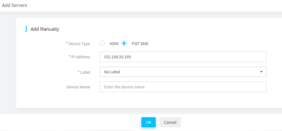
¡ To add a FIST SMS server node, select FIST SMS for Device Type. Specify the FIST SMS IP address and name of the server.
Figure 46 Adding a FIST SMS server node
5. Click OK.
Import servers
About this task
Perform this task to import servers to FIST from a file.
Prerequisites
Before you import servers to FIST, first prepare a valid import file that contains the servers you want to import. You can download the import file template on the Import Devices page and then fill in the device information as needed.
Table 8 lists the supported templates.
|
Template |
Description |
|
template-1.txt |
Template in TXT format. Each line represents a device in the format of IP address, username, password, port number (optional). For an HDM server node, specify the IP address, username, password, and port number (optional). For a FIST SMS server node, just specify the IP address. |
|
template-2.xlsx |
Template in XLSX format. Each row represents a device with the device type, IP address, username, password, and port number (optional) listed sequentially from column 1 to column 5. For an HDM server node, specify the device type, IP address, username, password, and port number (optional). For a FIST SMS server node, just specify the device type and IP address. |
|
template-3.xls |
Template in XLS format. Each row represents a device with the device type, IP address, username, password, and port number (optional) listed sequentially from column 1 to column 5. For an HDM server node, specify the device type, IP address, username, password, and port number (optional). For a FIST SMS server node, just specify the device type and IP address. |
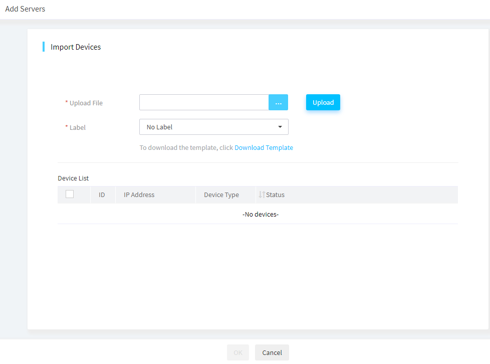
Procedure
1. In the navigation pane, select Menu > Devices > Server List.
2. Click Add, and then select Bulk Import.
3. In the Upload File field, click … to select the import file, and then click Upload to upload the file.
FIST displays all devices in the file on the device list.
4. Select a label.
5. Select the servers you want to import to FIST, and then click OK.
The import process might take a while.
Figure 47 Importing servers to FIST
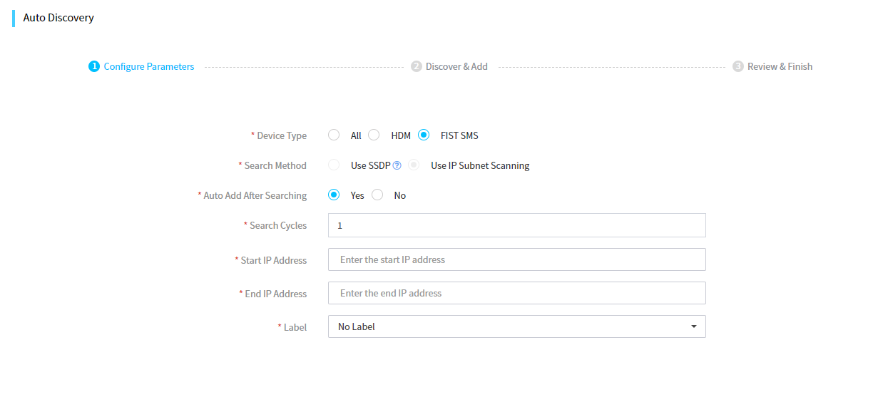
Add servers through auto discovery
About this task
Auto discovery allows you to search the network for servers by using SSDP or by using IP subnet scanning and add the found servers to FIST. Both HDM server nodes and FIST SMS server nodes can be added through auto discovery.
Restrictions and guidelines
The SSDP method is available only for G6 servers and servers of later generations.
· FIST management of servers can only be implemented in Layer 2 networks.
· FIST and HDM must be enabled with IPv6. HDM must also be enabled with SSDP and uses port 1900 for listening.
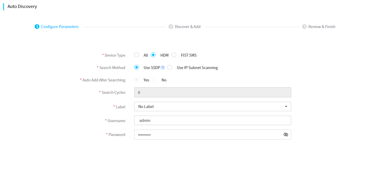
Procedure
1. In the navigation pane, select Menu > Devices > Server List.
2. Click Add, and then select Auto Discovery.
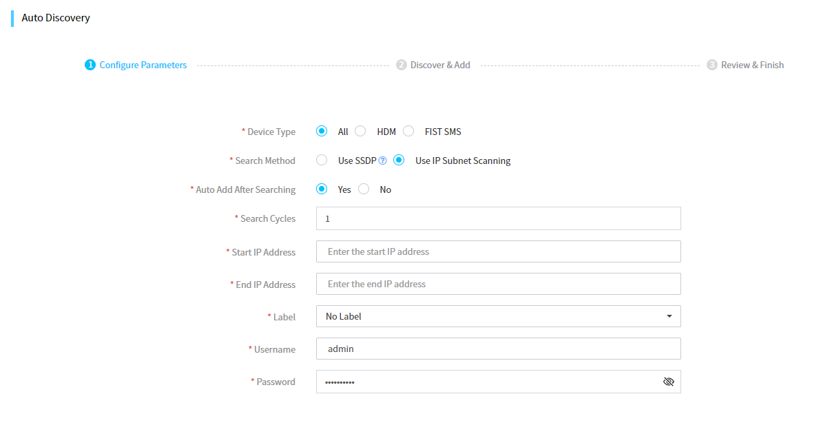
3. Select the device type and the search method.
¡ To search for HDM server nodes only or for both FIST SMS and HDM server nodes, select HDM or All for Device Type.
- If you select Use IP Subnet Scanning, enter the start and end IP addresses of an IP address range.
- If you select Use SSDP, enter the HDM login username and password of the servers.
Figure 48 Searching for both HDM and FIST SMS nodes or for HDM nodes only
¡ To search for FIST SMS server nodes only, select FIST SMS for Device Type. Only the IP subnet scanning method is supported for this device type. Enter the start and end IP addresses of an IP address range.
Figure 49 Searching for FIST SMS server nodes only
4. Select whether to add the discovered servers automatically.
¡ If you select Use SSDP for Search Method, the discovered servers will be added automatically by default.
¡ If you select Use IP Subnet Scanning for Search Method and select Yes for Auto Add After Searching, enter the number of search cycles in the Search Cycles field.
Figure 50 Adding discovered servers automatically
5. Select a label.
6. Click Search.
¡ If you select No for Auto Add After Searching, select servers to be added from the discovered server list, and then click Add.
Figure 51 Adding selected servers to FIST
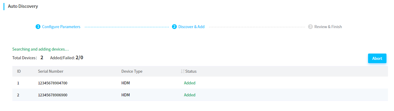
¡ If you select Yes for Auto Add After Searching, FIST automatically adds a server once it discovers the server. To abort the process, click Abort at the upper right corner of the discovered server list.
Figure 52 Automatically adding discovered servers to FIST
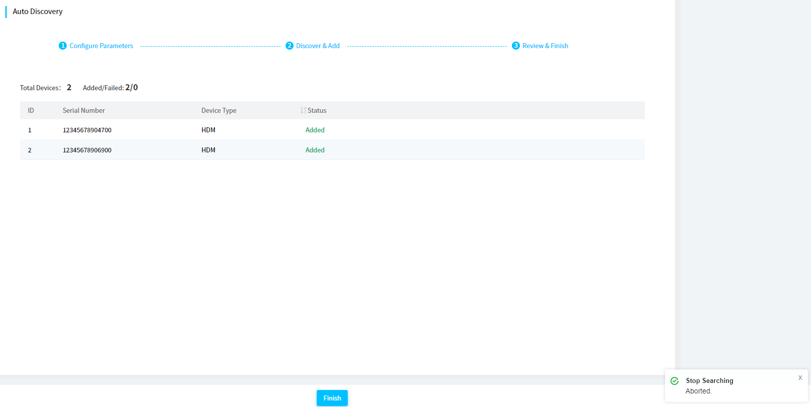
7. To go back to the Server List page and view the newly added servers, click Back in the upper left corner of the page.
Configure IP settings in bulk
Introduction
Perform this task to edit the HDM management IP addresses of multiple servers in bulk by using IP configuration template files. The servers can be those managed by FIST or those not managed. This feature is available only for servers using HDM-3.10 or a later version.
This feature is applicable to the following scenarios:
· The default IP address (192.168.1.2) that comes with a device is not edited.
· The default IP address (192.168.1.2) that comes with a device has changed.
In the scenario where the default IP address (192.168.1.2) that comes with a device is not edited:
Procedure
1. In the navigation pane, select Menu > Devices > Server List.
2. Click Bulk IP Settings. The Bulk IP Settings page as shown in Figure 53 opens.
For information about how to configure this feature, click Usage Guidelines.
Figure 53 Configure IP settings in bulk
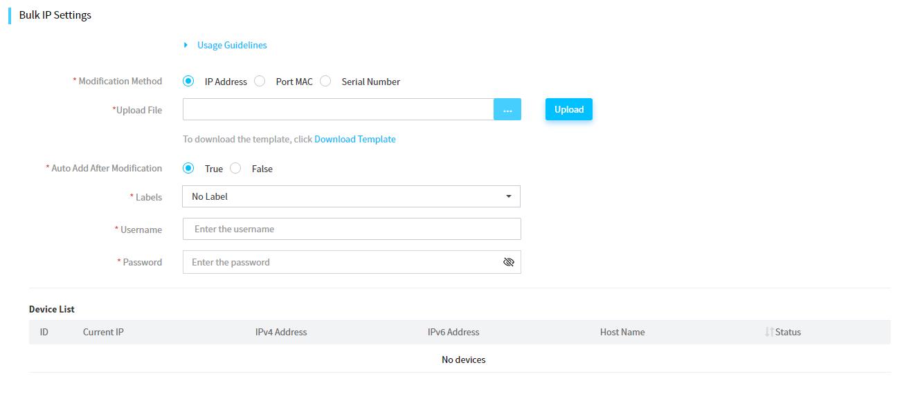
3. In the Modification Method filed, select a method to configure IP settings in bulk. Options include IP Address, Port MAC, and Serial Number. If you select Serial Number, you can select whether to support SSDP. SSDP is available for only G6 servers and servers of later generations.
The port MAC and serial number modification method is application to scenarios where the default device IP address (192.168.1.2) has not been changed. The IP address modification method is application to scenarios where the default device IP address (192.168.1.2) has been changed.
4. In the Upload File field, click the … icon. In the dialog box that opens, select the device IP configuration file.
To download the port MAC, serial number, or IP address template, click Download Template. Fill in device information as instructed in the README file downloaded together with the template. Information carried in an IP address template are as shown in Table 9.
Table 9 IP address template description
|
Template |
Description |
|
template-IP.xlsx and template-IP.xls |
Each row represents a device and the columns from the left to right represent: current IP address (IPv4 or IPv6), dedicated IPv4 mode, address, subnet mask, gateway, dedicated IPv6 mode, address, prefix, gateway, shared port IPv4 mode, address, subnet mask, gateway, shared port IPv6 mode, address, prefix, gateway, and host name. You must specify the current IP address and a minimum of one target IP address (shared port IPv4, shared port IPv6, dedicated port IPv4, or dedicated port IPv6). To avoid conflicts, make sure the current IP address is different from any target IP address, and the target IP addresses are different from each other. |
5. Click Upload. After upload, you can view the uploaded device information from the device list, as shown in Figure 54.
Figure 54 Device list in bulk IP settings
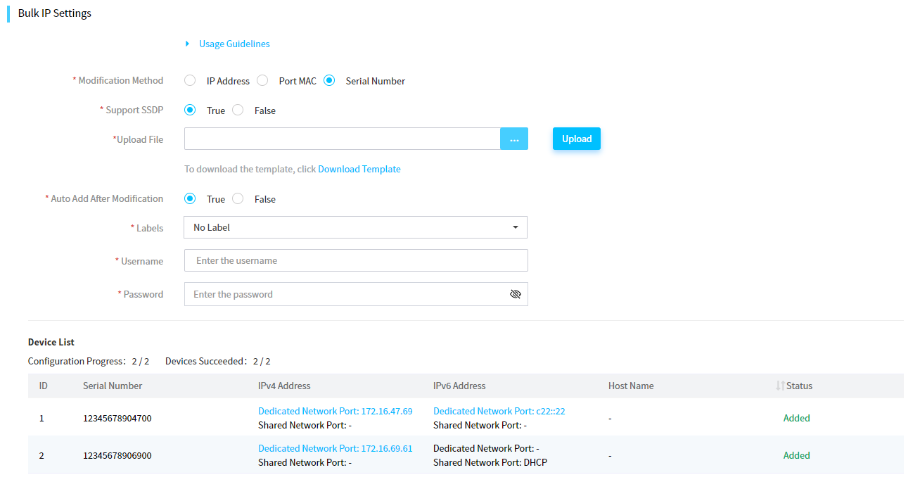
6. Configure the Auto Add After Modification field. If the servers are not required to be managed by FIST after the modification, you can select False. If the servers are required to be managed by FIST after the modification, select True.
7. Select a label.
8. In the Username and Password fields, enter the HDM username and password, respectively.
9. Click OK.
The system starts editing HDM management IP addresses of the servers in bulk. If you select True for Auto Add After Modification, the system will add the servers to the server list after the IP addresses are edited. This process might take a long time.
10. Click Back to return to the server list.
Delete servers
About this task
Perform this task to delete servers from FIST.
Procedure
1. In the navigation pane, select Menu > Devices > Server List.
2. Select the servers you want to delete, click More in the top left corner, and then select Delete.
3. Click OK in the confirmation dialog box that opens.
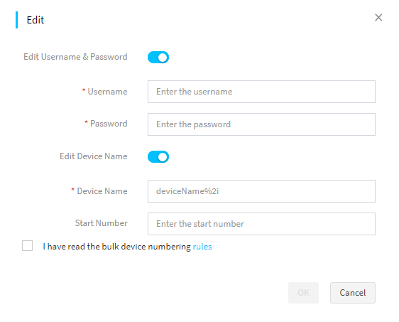
Edit servers
About this task
Perform this task to bulk edit the names and HDM login credentials for servers managed by FIST.
Procedure
1. In the navigation pane, select Menu > Devices > Server List.
2. Select the target servers, click More, and then select Edit.
3. Select the Edit HDM Username & Password option, and then specify the new HDM login user name and password for the servers.
4. Select the Edit Server Name option, and then rename the selected servers as follows:
¡ To assign a unique name that contains an automatically generated sequence number to each server, enter the device name with string %*i and specify the start sequence number. Replace the asterisk (*) in the %*i string with the number of digits you want to include in the sequence number, which must be an integer in the range of 1 to 4. To use a one-digit sequence number, specify %*i as %1i or %i.
For example, with the device name set to FIST%4i and the start number set to 6, FIST will rename the first server as FIST0006 and subsequent servers as FIST0007, FIST0008, and so on.
¡ To assign a uniform name to all the selected servers, enter the server name and leave the Start Number field empty.
5. Click OK.
Figure 55 Editing server settings
Manage labels
You can create labels and assign labels to servers to facilitate server identification and filtering.
Restrictions and guidelines
You can assign a maximum of five labels to a server.
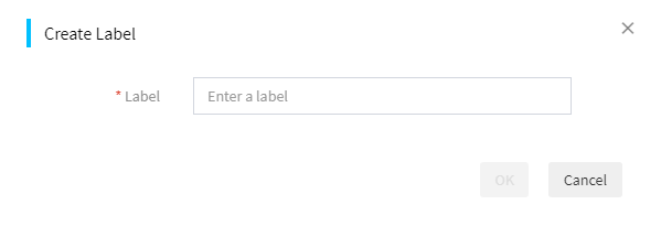
Create a label
1. In the navigation pane, select Menu > Devices > Server List.
2. Perform either of the following steps:
¡ To create a label and assign it to designated servers, select the servers, click Manage Labels in the upper right corner, and then select Create Label.
¡ To create a label without assigning it to any servers, directly click Manage Labels in the upper right corner, and then select Create Label.
3. Enter the label name, and then click OK.
Figure 56 Creating a label
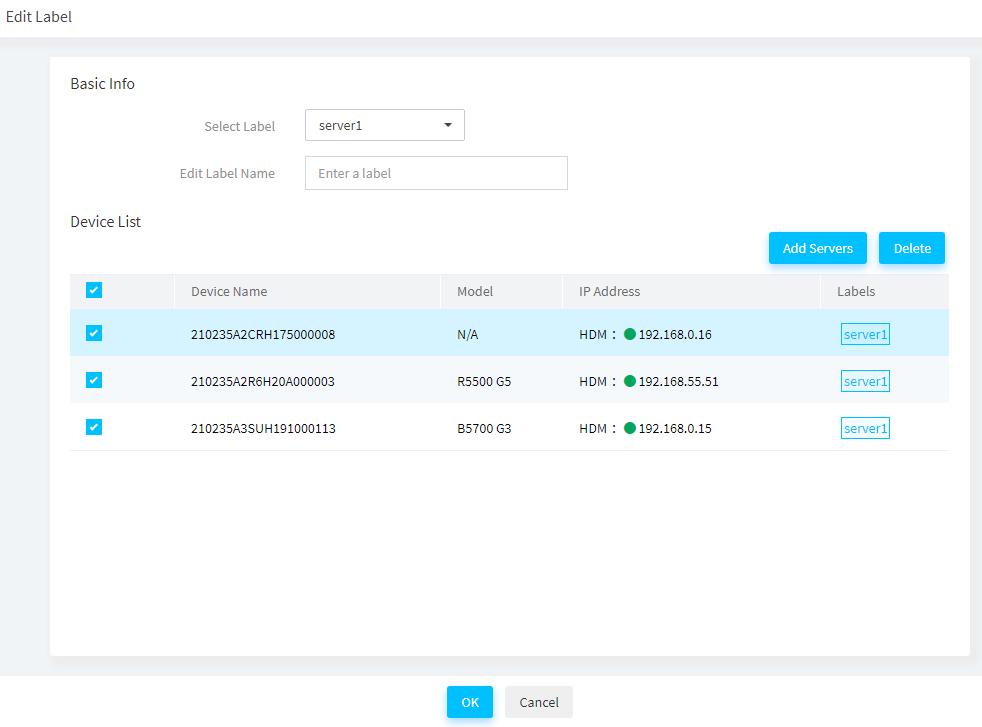
Edit a label
4. In the navigation pane, select Menu > Devices > Server List.
5. In the upper right corner, click Manage Labels, and then select Edit Label.
6. From the Select Label list, select the label you want to edit.
7. To change the label name, enter the new label name in the Edit Label Name field.
8. In the server list area, select the servers to which you want to assign the label.
9. To delete one or more servers from the server list, select the servers, and then click Delete.
10. Click OK.
Figure 57 Editing a label
Delete a label
1. In the navigation pane, select Menu > Devices > Server List.
2. In the upper right corner, click Manage Labels, and then select Delete Label.
3. From the Select Label list, select the label you want to delete.
4. Click OK to delete the label from all devices that have the label assigned.
Launch a remote console
About this task
Perform this task to launch a KVM or H5 KVM remote consoles to configure and manage a server.
Restrictions and guidelines
· Only an account with the KVM remote control privilege can start the remote console.
· A maximum of four concurrent remote control sessions are supported.
· A flashing UID LED indicates that the remote console on a server is active.
Procedure
1. In the navigation pane, select Menu > Devices > Server List.
2. Click the KVM or H5 KVM in the Actions column for the target server.
View server information
View server details
About this task
You can view the detailed information of a server on the Server Details page, which provides server information on these tabs: Summary, Hardware Details, Temperature Info, and Power Settings.
Restrictions and guidelines
FIST does not provide information about the power supplies or fans for a blade server.
Procedure
1. In the navigation pane, select Menu > Devices > Server List.
2. Click the name of the server whose detailed information you want to view.
3. On the Server Details page, click a tab to view the information displayed on the tab.
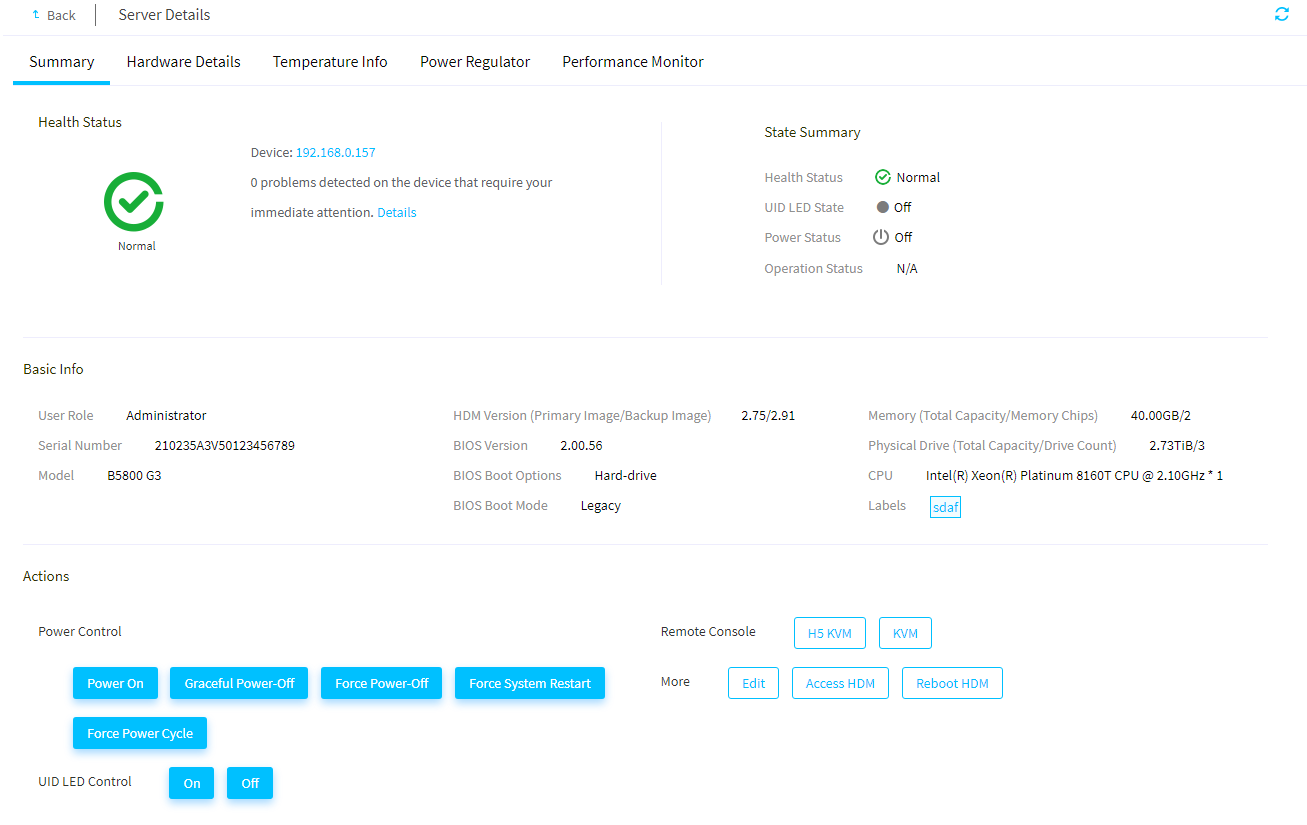
Available tabs include:
¡ Summary: Displays the overall health, status, and basic information of the server, and provides management options for the server.
Figure 58 Summary tab
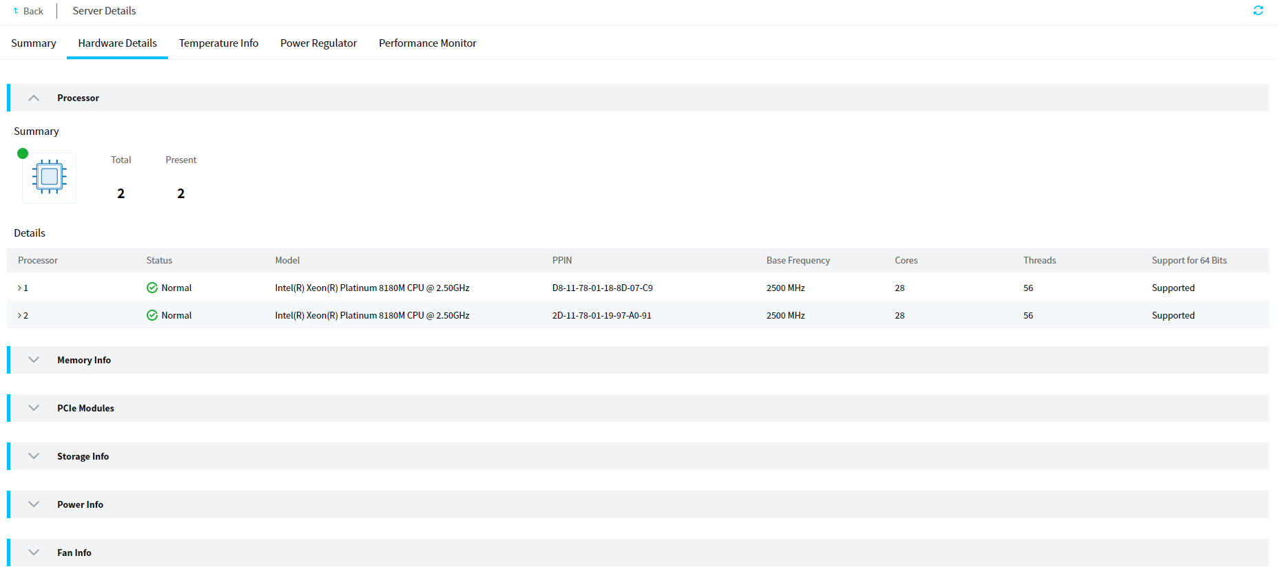
¡ Hardware Details: Displays information about the processors, memory, PCIe modules, storage controllers, logical drives, physical drives, power supplies, fans, and firmware on the server.
Figure 59 Hardware Details tab
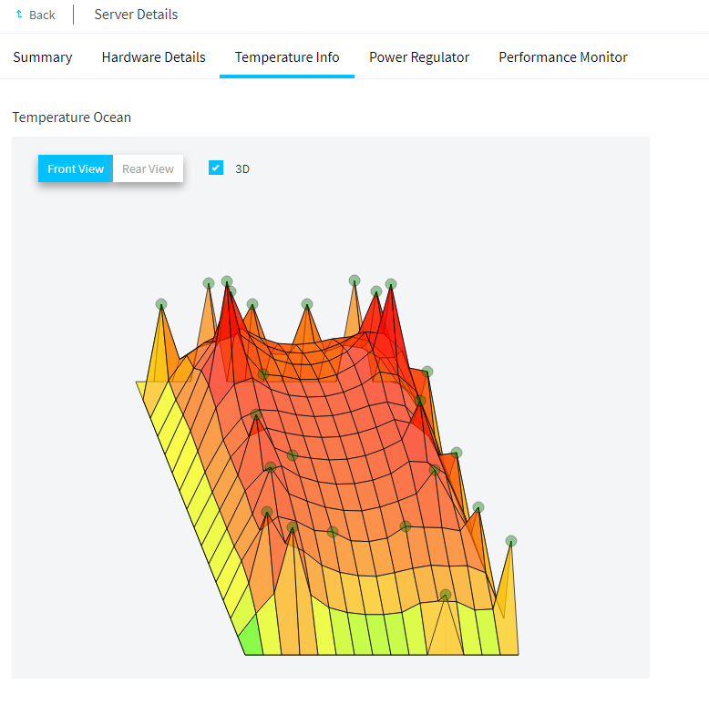
¡ Temperature Info: Displays temperature information about the server in a temperature heatmap. Hover over the map to view the temperature sensor name, status, and reading.
Figure 60 Temperature Info tab
¡ Power Regulator: Allows you to view and configure power settings for the server. For information about how to set the power settings for the server, see "Configure power capping settings."
Figure 61 Power Regulator tab
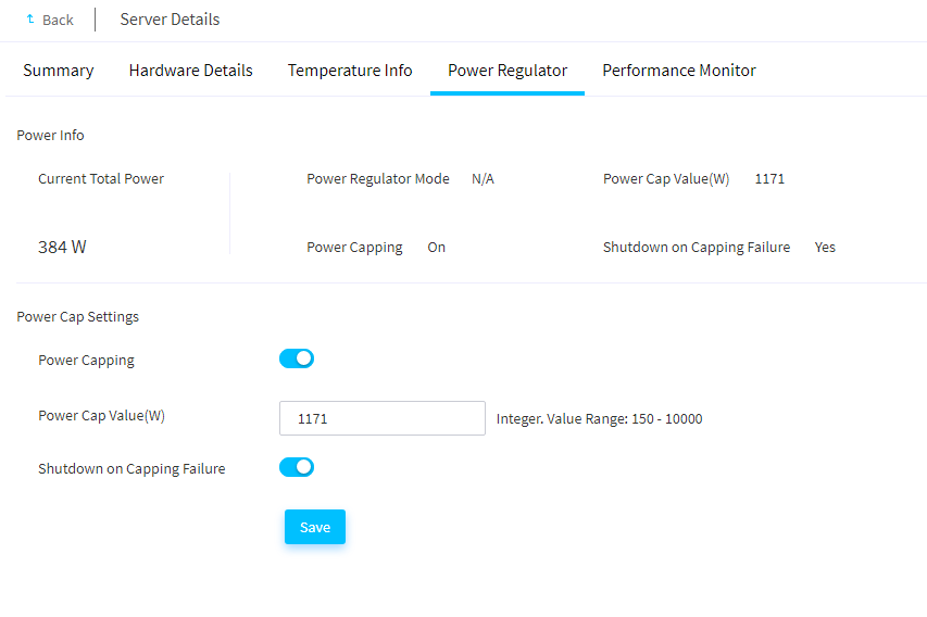
Configure power capping settings
About this task
From the Power Regulator tab of the Server Details page, you can configure the power capping settings for the server.
The power capping feature allows you to limit the power consumption of a server to a power cap value that is lower than or equal to the maximum rated power of the server.
When the power cap value is exceeded, the server attempts to decrease power consumption by automatically decreasing the operating frequency of system components such as processors. Power capping fails if the power consumption cannot drop below the power cap value in 30 seconds.
You can configure the server to shut down or continue to run on power capping failure.
Procedure
1. In the navigation pane, select Menu > Devices > Server List.
2. Click the name of a server to enter the server details page.
3. Click the Power Regulator tab.
4. Select Enable for Power Capping to enable power capping.
5. Set the power cap value.
Power capping is at the expense of system performance. Select the power cap value carefully to avoid undesirable decrease in performance, especially when the server contains power intensive components, such as GPUs and SSDs.
6. (Optional.) Enable or disable the Shutdown on Capping Failure feature as needed.
7. Click Save.
View performance monitoring data of a FIST SMS server node
About this task
For a FIST SMS server node, you can view its physical resource usage information on the Server Performance Monitor page. FIST collects the CPU usage, drive space usage, memory usage, network throughput, cache memory, GPU usage, drive I/O, drive throughput, drive read/write ratio, drive queue depth, I/O latency, NFS client read/write speed, NFS server read/write speed, system load, inlet temperature, and power information of managed FIST SMS server nodes at 30-second monitor intervals. You can view the past 30 days' resource usage data for a FIST SMS server.
The NFS server read/write speed, NFS client read/write speed, and system load are available only in Linux operating systems.
To monitor the NFS server read/write speed, GPU usage, disk information, and physical resources data that requires a CLI-based obtaining method, you must first configure the environment. For detailed information about the resource obtaining methods, see H3C Servers FIST SMS User Guide.
· GPU usage information: Requires installing and running nvidia-smi.
· NFS client read/write speed and NFS server read/write speed: Requires installing the NFS client and setting up the server environment.
To use the iostat tool that comes with the system to obtain resources, value obtaining fails if the corresponding field is missing in iostat. In this case, manual installation is required. To manually install iostat, use the software package manager or the source code. To use the source code method, use the symbolic link to replace the iostat file path.
If the FIST SMS of a server is not added to FIST, the performance monitoring page of the server displays only the history power and temperature trend graphs for the server.
Restrictions and guidelines
· If FIST failed to obtain the server information for a monitoring period, the data corresponding to the monitoring period is displayed as empty. A message is displayed to indicate that the connection to the FIST SMS node failed.
· When the usage of a specific type of resources exceeds the corresponding alarm threshold, the server will send the corresponding SNMP alarms. When the usage drops below the threshold, the server will send messages for clearing the SNMP alarms. To use FIST to listen to SNMP alarms, configure related functions on the alarm forwarding page. For more information, see "Configure alarm forwarding."
Procedure
1. In the navigation pane, select Menu > Devices > Server List.
2. Click the device name of the FIST SMS server whose monitoring data you want to view.
3. Click the Monitor tab.
The tab displays the following physical resource usage information of the FIST SMS server node:
¡ CPU Usage: Displays the CPU usage of applications running on the server.
¡ Drive Usage: Displays the percentage of used drive space to the total available drive space for the server.
¡ Memory Usage: Displays the percentage of memory space used by all processes to the total available memory space.
¡ Network Throughput: Displays the transmission and receiving rates (in Mbps) of the selected network adapter. In the upper right corner of the line chart, select the MAC address of the network adapter whose data you want to view.
¡ History Temperature: Displays inlet temperature change trend of the server.
¡ History Power: Displays power change trend of the server, in watts.
¡ CPU Usage Alarm Threshold: Threshold for the CPU usage to trigger an alarm. The value 0 indicates disabling alarming.
¡ Memory Usage Alarm Threshold: Threshold for the memory usage to trigger an alarm. The value 0 indicates disabling alarming.
¡ Drive Usage Alarm Threshold: Threshold for the drive usage to trigger an alarm. The value 0 indicates disabling alarming.
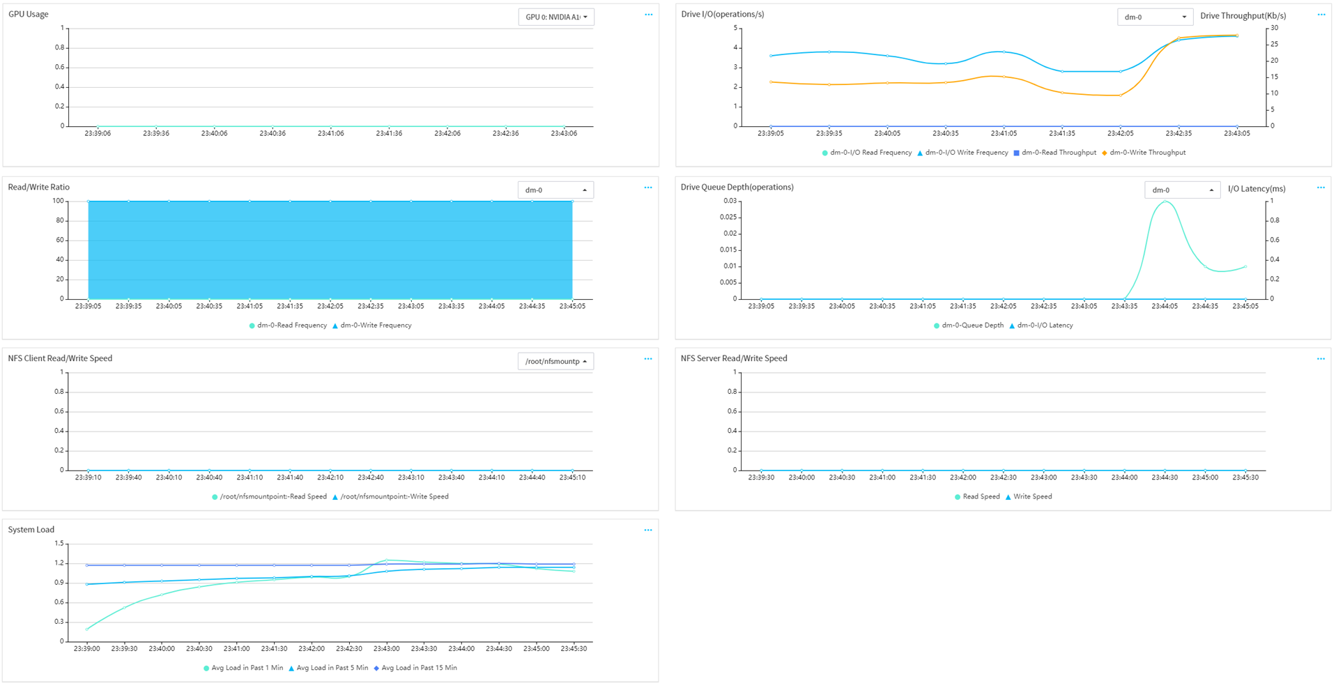
¡ Cache Memory (MB): Cache memory size.
¡ GPU Usage: Percentage of GPU resources used by running services to the total available GPU resources.
¡ Drive I/O (operations/s): Drive read/write in a given unit of time.
¡ Read/Write Ratio: Percentage of drive read/write operations to the total read/write operations in a given unit of time.
¡ Drive Queue Depth (operations): Average queue length for drive read/write operations in a given unit of time.
¡ Drive Throughput (kb/s): Read and write throughput in a given unit of time.
¡ I/O Latency (ms): Average waiting time for a drive read/write operation to finish in a queue in a given unit of time.
¡ NFS Client Read/Write Speed: Data amount of NFS client read/write operations in a given unit of time.
¡ NFS Server Read/Write Speed: Data amount of NFS server read/write operations in a given unit of time.
¡ System Load: Computing workload of the computer system in a given unit of time.
Each line chart shows data collected over a time span of 3 hours.
Figure 62 Server Performance Monitor page (1)
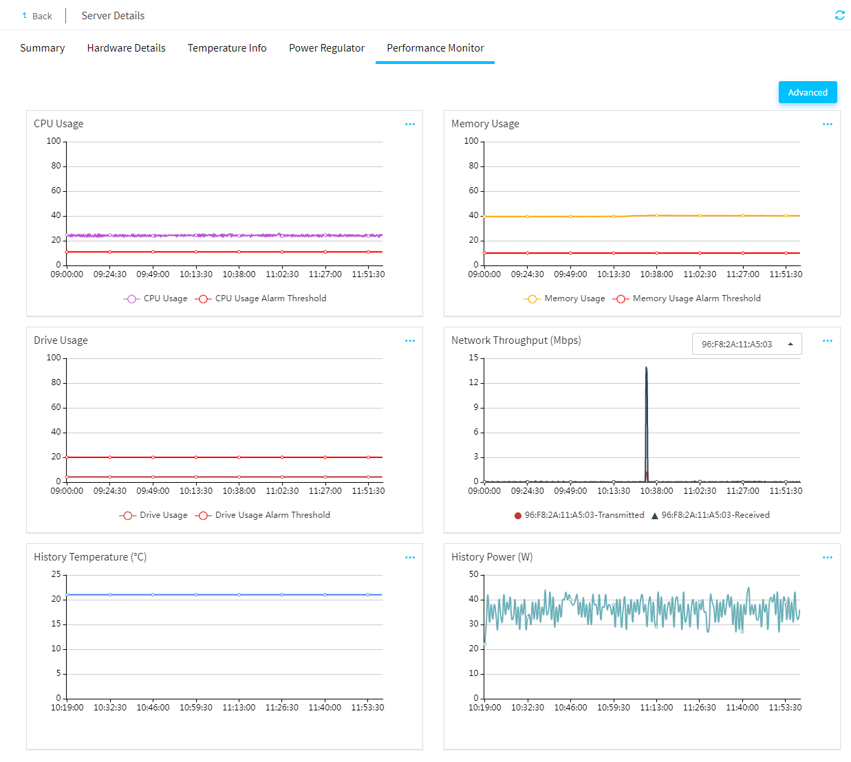
Figure 63 Server Performance Monitor page(2)
4. Roll the mouse wheel to adjust the size of a chart and view the data for each monitoring period.
5. (Optional.) Click Advanced. You can view and set the usage alarm thresholds of the server. After you set a threshold, the threshold will be marked by a red line in the line chart.
Manage servers remotely through FIST
Power on or power off servers
About this task
Perform this task to power on or power off servers remotely from FIST.
Restrictions and guidelines
If you use FIST to power on a large number of servers at the same time, the electric current might be too large. As a best practice, operate these servers in multiple batches and power on servers in staggered shifts.
Procedure
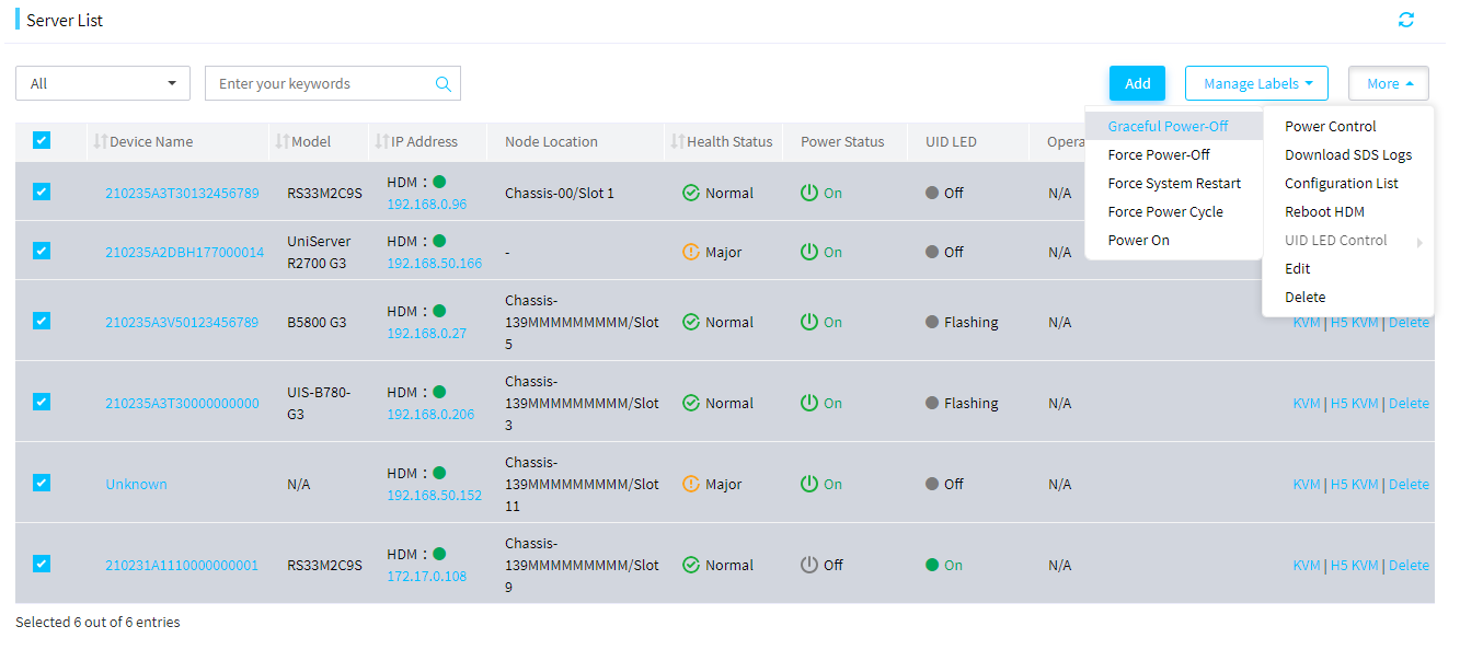
1. In the navigation pane, select Menu > Devices > Server List.
2. Select the target servers, click More, and then select Power Control.
3. Select one of the following power options as needed:
¡ Graceful Power-Off: Power off the servers gracefully. This button mimics a physical momentary press of the power button on the server.
¡ Force Power-Off: Force the servers to power off. This button mimics a physical press and hold of the power button on the server.
¡ Force System Restart: Reboot the servers without powering off them.
¡ Force Power Cycle: Force the servers to reboot immediately.
¡ Power On: Power on the servers. This button mimics a physical momentary press of the power button on the server.
4. In the dialog box that opens, select Operating instructions lick OK.
Figure 64 Powering on or powering off servers
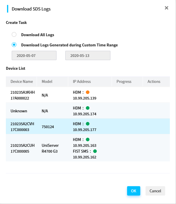
Download SDS logs
About this task
Perform this task to download and save SDS logs of managed servers to local .sds files.
Procedure
1. In the navigation pane, select Menu > Devices > Server List.
2. Select the servers whose SDS logs you want to download, click More, and then select Download SDS Logs.
3. Select whether to download all SDS logs or only SDS logs generated during a specific time range.
4. To download only SDS logs generated during a specific time range, specify the log generation time range as needed.
5. Click OK.
FIST starts to download the SDS logs of the selected servers and displays the device-specific downloading progress on the device list.
Figure 65 Downloading SDS logs
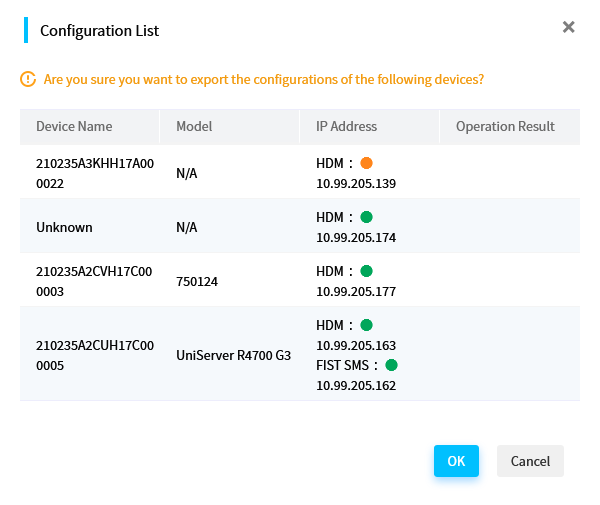
Export the configuration information of servers
About this task
Perform this task to export the basic configuration information of selected servers to .json files. The exported information includes the server model, HDM IP address, BIOS/HDM version, processor, memory, storage, and PCIe module information.
FIST exports the configuration information of each selected server to a separate file. In addition, it creates a file to record all servers (identified by their names) and their PCIe module information. All those files will be compressed to an archive and can be downloaded locally.
Procedure
1. In the navigation pane, select Menu > Devices > Server List.
2. Select the servers whose configuration information you want to export, click More, and then select Configuration List.
3. Click OK to export the configuration of the selected servers.
4. Save the exported server configuration file to the local device.
Figure 66 Exporting the configuration information of selected servers
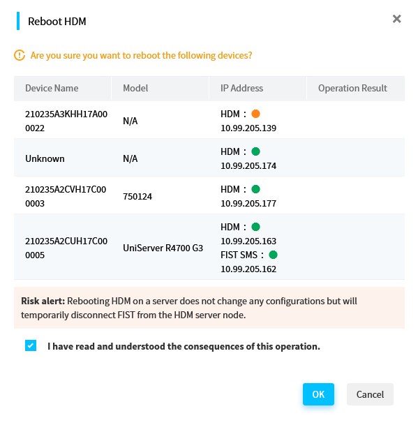
Reboot HDM
About this task
Perform this task to reboot HDM on selected servers.
Restrictions and guidelines
· Rebooting HDM on a server will temporarily disconnect the server from FIST. The connection is automatically restored after HDM starts up.
· Video files cannot survive an HDM reboot. Back up the video files on a server before you reboot HDM on the server.
· To avoid HDM and operating system anomalies, do not power on or power off the server during the HDM reboot process.
Procedure
1. In the navigation pane, select Menu > Devices > Server List.
2. Select the target servers, click More, and then select Reboot HDM.
3. Verify the operation information, and then select I have read and understood the consequences of this operation.
4. Click OK.
Figure 67 Rebooting HDM on selected servers
Turn or turn off the UID LED for servers
About this task
Perform this task to turn on or turn off the UID LED of servers remotely from FIST. Turning on the UID LED for a server helps locate the server, especially in a high-density server environment.
Restrictions and guidelines
You cannot turn on or turn off the UID LED for a server with a flashing UID LED. A flashing UID LED indicates that a firmware update is being performed on the server or the remote console is being used on the server.
Procedure
1. In the navigation pane, select Menu > Devices > Server List.
2. Select the target servers, and then click More.
3. Select UID LED Control, and then select On or Off.
4. Verify the operation information, and then click OK.
Figure 68 Turning or turning off the UID LED for servers
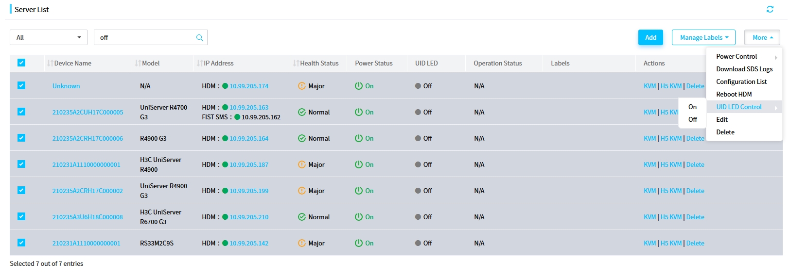
Manage switches
FIST can manage switches of the following models:
· H3C S6800-54QT
· H3C S6850-56HF
· H3C S6800-54QF
· H3C UIS M8380-C
· H3C UIS M8310
Use the switch management functions
Perform this task to manage switches. For example, you can add and delete a switch, update the user settings for a switch, and log in to the SSH console of a switch.
Add a switch
About this task
Perform this task to add switches to FIST for management. You can add up to 30 switches to FIST.
Prerequisites
· Obtain the management IP address of the switch.
· Obtain the username and password of the system user that has admin privilege to manage the switch, and specify that the user can use the HTTP service.
· Enable NETCONF over SOAP on the switch.
· Make sure the network where FIST resides and the management network of the switch to be added can reach each other.
Procedure
1. Obtain the management IP address of the switch and the username and password of the system user that has admin privilege to manage the switch.
2. Log in to the CLI of the switch and perform the following steps:
# Enable NETCONF over SOAP on the switch.
[Sysname] netconf soap http enable
# Enter the system user view and specify that the user can use the HTTP service. This example uses user admin.
[Sysname] local-user admin
[Sysname-luser-manage-admin] service-type http
3. Add a secondary IP address that belongs to the management network of the switch:
a. Execute the display ip interface brief command on the switch. As shown in Figure 69, the IP address of the M-GE0/0/0 port is the management IP address of the switch.
Figure 69 Obtaining the management IP address of the switch
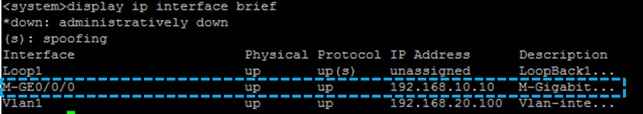
4. Add the switch to FIST:
a. Log in to FIST.
b. In the navigation pane, select Menu > Devices > Switch List.
c. Click Add Switch. In the dialog box that opens, enter related information and click OK.
Figure 70 Adding a switch
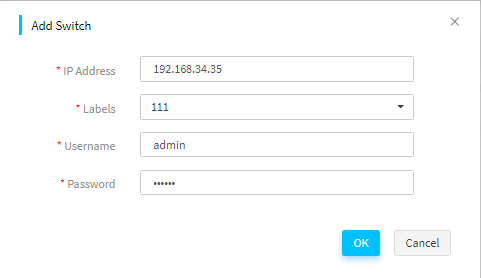
d. Verify that the newly added switch is displayed on the switch list.
Figure 71 Adding a switch
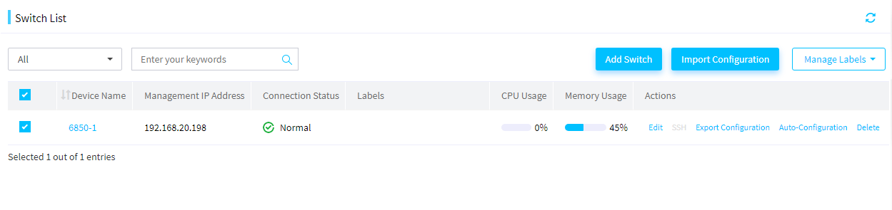
Log in through SSH console
About this task
Through the SSH console, you can log in to the managed switch through SSH and open the CLI of the switch. To use this function, make sure the SSH service is enabled on the managed switch and the login user supports the SSH service.
Restrictions and guidelines
· If the SSH remote console window fails to be loaded correctly, click the link provided at the bottom of window to load the certificates on a new page. After the load is completed, return to the remote console window and click Refresh. If you will not use the SSH console for a long period of time, execute a command to exit the SSH console.
· When you are using the SSH console to log in to the CLI of the managed switch, do not click Refresh. Otherwise, you will be logged out.
· The SSH feature is not available if you set up the FIST environment in a Windows operating system and add switches to FIST.
Procedure
1. In the navigation pane, select Menu > Devices > Switch List.
2. Click SSH in the Actions column for the switch.
Figure 72 Log in to a switch through SSH
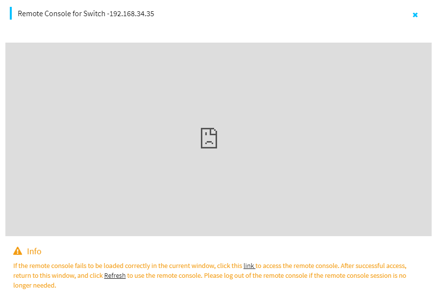
Export the configuration of a switch
About this task
Perform this task to export the configuration of a switch and save the exported switch configuration in a switch configuration template on the Menu > Templates > Switch Configuration Templates page.
This feature is available only for H3C S6850-56HF and H3C S6800-54Q switches.
Restrictions and guidelines
· Do not operate on the switch (through CLI, SNMP, or other methods) while FIST is exporting the switch configuration.
· Configuration export is a resource-intensive operation. Make sure the switch has enough resources before you export its configuration.
· Do not set the name of a switch configuration template to FIST.cfg.
Procedure
1. In the navigation pane, select Menu > Devices > Switch List.
2. Click Export Configuration in the Actions column for the switch whose configuration you want to export.
3. In the dialog box that opens, click OK.
Import configuration to a switch
About this task
Perform this task to import the configuration in a switch configuration template to a managed switch.
This feature is available only for H3C S6850-56HF and H3C S6800-54Q switches.
Restrictions and guidelines
· After you import configuration to a switch, FIST might fail to communicate with the switch because of switch address conflicts. To resolve the issue, manually edit the IP address of the switch and add the switch to FIST again.
· Do not import configuration to a switch on which the configuration export operation in progress.
· You can import configuration to a switch only by using a switch configuration template with a matching switch model.
· Do not operate on the switch (through CLI, SNMP, or other methods) while FIST is importing configuration to the switch.
· Configuration import is a resource-intensive operation. Make sure the switch has enough resources before you import configuration to it.
Procedure
1. In the navigation pane, select Menu > Devices > Switch List.
2. Select the target switch, and then click Import Configuration.
3. In the dialog box that opens, select the configuration template you want to import to the switch, and then click OK.
Figure 73 Selecting a configuration template to import to the switch
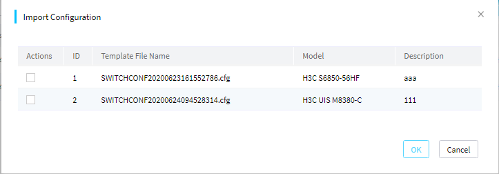
Configure auto-configuration
The auto-configuration feature allows you to bind a server template to a switch port to enable automated configuration of the switch port and the server connected to that port.
When a server is added to FIST, FIST checks the following items:
· Whether the management port of the server is correctly connected to a switch port that has a bound server template.
· Whether the auto-configuration feature is enabled on FIST.
If yes, FIST will automatically apply the bound server template to the server and configure the switch port according to the connection settings in the server template.
Restrictions and guidelines
LLDP must be enabled both globally and on the corresponding switch ports for the auto-configuration feature to work correctly.
FIST can apply the bound server template of a switch port to the connected server only when the server is powered off.
Procedure
1. In the navigation pane, select Menu > Devices > Switch List.
2. Click the device name of a switch to enter the details page.
3. Click the Auto-Configuration tab.
Figure 74 Auto-Configuration tab
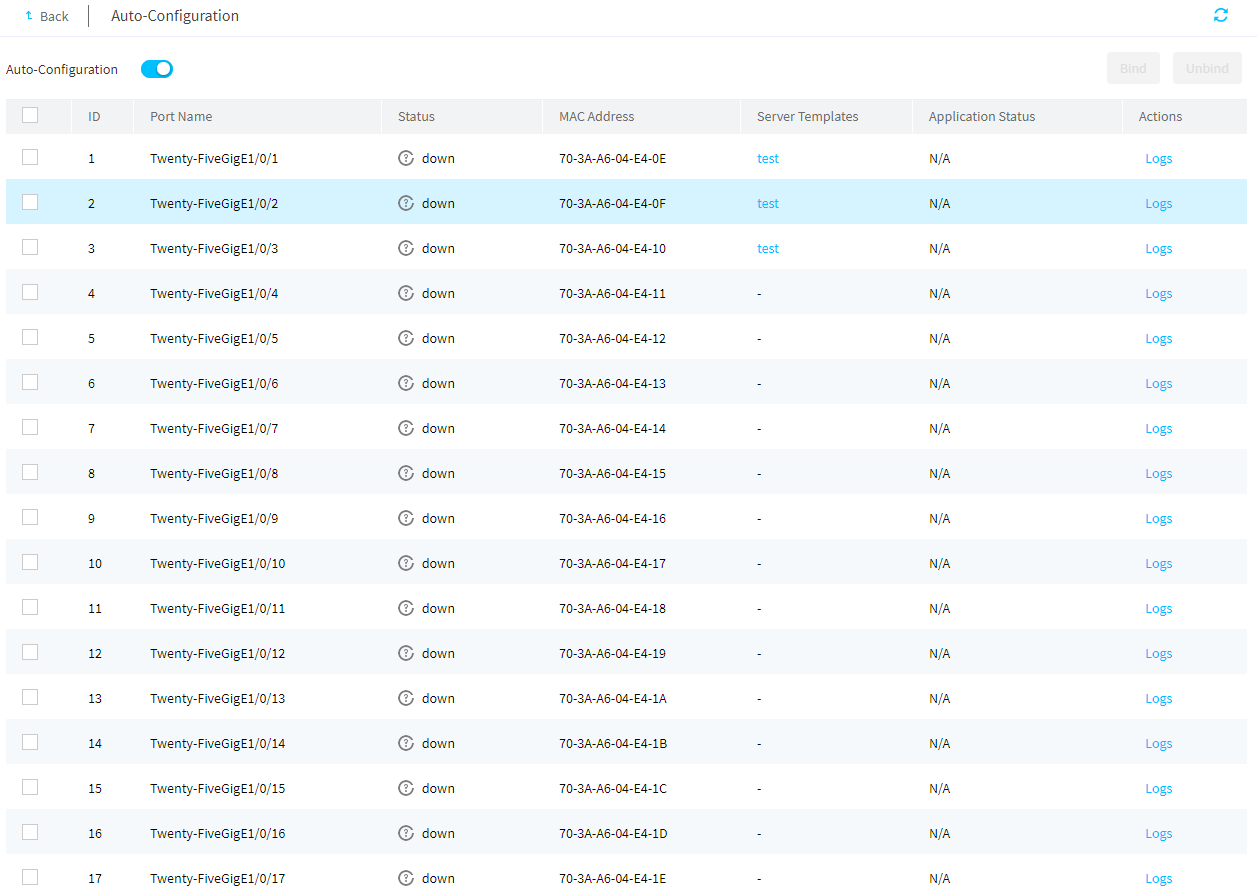
4. On the switch port list, select the switch ports to which you want to bind a server template, and then click Bind.
5. In the dialog box that opens, select the server template you want to bind to the selected switch ports, and then click OK.
Figure 75 Binding a server template to the selected switch ports
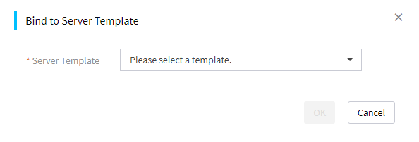
6. Turn on the Auto-Configuration toggle switch to enable the auto-configuration feature.
7. To remove the server template bindings for some switch ports, select the ports, and then click Unbind. In the confirmation dialog box that opens, click OK.
8. To view the server template application logs for a switch port, click the Logs link in the Actions column for the switch port.
Delete a switch
1. In the navigation pane, select Menu > Devices > Switch List.
2. Click Delete in the Actions column for the switch that you want to delete. In the dialog box that opens, click OK.
Update information of a switch
About this task
You can update the username and password of a switch in FIST, so that the username and password are consistent with those of the switch and the switch can pass authentication.
Procedure
1. In the navigation pane, select Menu > Devices > Switch List.
2. Click Edit in the Actions column for the switch that you want to edit.
3. Enter related information and click OK.
Search for switches
About this task
Perform this task to search for switches by name, IP, and other information.
Procedure
1. In the navigation pane, select Menu > Devices > Switch List.
2. In the search area, select the search criterion and enter the search keyword. Available search criteria include device name, IP address, connection state, CPU usage, and memory usage.
View switch details
View the summary, card, port, and interface information of a switch
About this task
Perform this task to access the Switch Details page. The page provides the following tabs:
· Summary—Displays the basic information of the switch, including the device name, model, version, and management IP address.
· Cards—Displays information about the cards on the switch, including the card name, model, status, CPU usage, and memory usage.
· Ports—Displays information about the physical Ethernet and FC ports on the switch. For each physical port, this tab displays its PVID, link type, MAC address, traffic statistics, and peer end information.
· Interfaces—Displays information about the logical interfaces on the cards of the switch. Supported logical interface types include Layer 2/Layer 3 aggregate interfaces, VLAN interfaces, Loopback interfaces, null interfaces, InLoopback interfaces, Register-Tunnel interfaces, VFC interfaces, and HDLC link bundle interfaces. For each interface, this tab displays its name, status, IP address, interface type, and other information.
Procedure
1. In the navigation pane, select Menu > Devices > Switch List.
2. Click the device name of a switch to enter the details page.
3. Click the Summary, Cards, Ports, or Interfaces tab to view information corresponding information about the switch.
Figure 76 Switch Details page
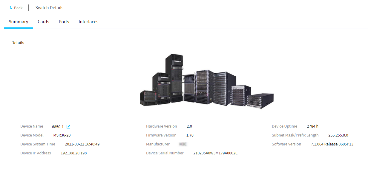
4. (Optional.) To rename the switch, click the Rename icon ![]() next to the device name on the Summary tab. In
the dialog box that opens, enter the new device name, and then click OK.
next to the device name on the Summary tab. In
the dialog box that opens, enter the new device name, and then click OK.
View the traffic statistics of a port or interface
About this task
Perform this task to view the traffic statistics of a physical port or logical interface on a switch card, such as the numbers of packets sent and received, and the packet drop statistics.
Procedure
1. In the navigation pane, select Menu > Devices > Switch List.
2. Click the device name of a switch to enter the details page.
3. Click the Ports or Interfaces tab, and then click Traffic Details in the Actions column for a port or interface.
|
|
NOTE: For interfaces on switches, you can view detailed traffic statistics about only aggregate interfaces. |
4. Click Last Statistics Polling Interval to view traffic statistics collected for the port or interface during the last polling interval. The default polling interval is 300 seconds.
Figure 77 Interface traffic statistics
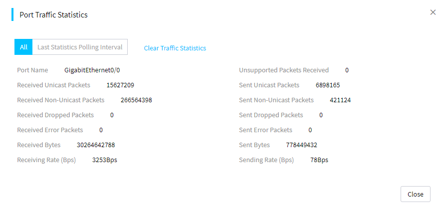
Manage switch labels
Perform this task to add, delete, and edit switch labels.
Add a switch label
You can assign labels to switches for ease of management as needed. You can add up to 1000 switch labels.
Procedure
1. In the navigation pane, select Menu > Devices > Switch List.
2. Click Manage Labels, and then select Create Label.
3. In the dialog box that opens, enter related information and click OK.
Figure 78 Adding a switch label
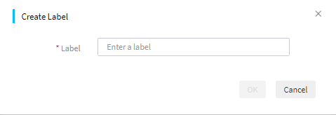
Edit a switch label
1. In the navigation pane, select Menu > Devices > Switch List.
2. Click Manage Labels, and then select Edit Label.
3. In the Basic Info area, select the label you want to edit and enter the new label name.
4. In the Device List area, click Add to select the devices to which you want to assign this label.
5. To remove the label from one or more devices, select the devices on the device list, and then click Delete.
6. Click OK.
Figure 79 Editing a switch label
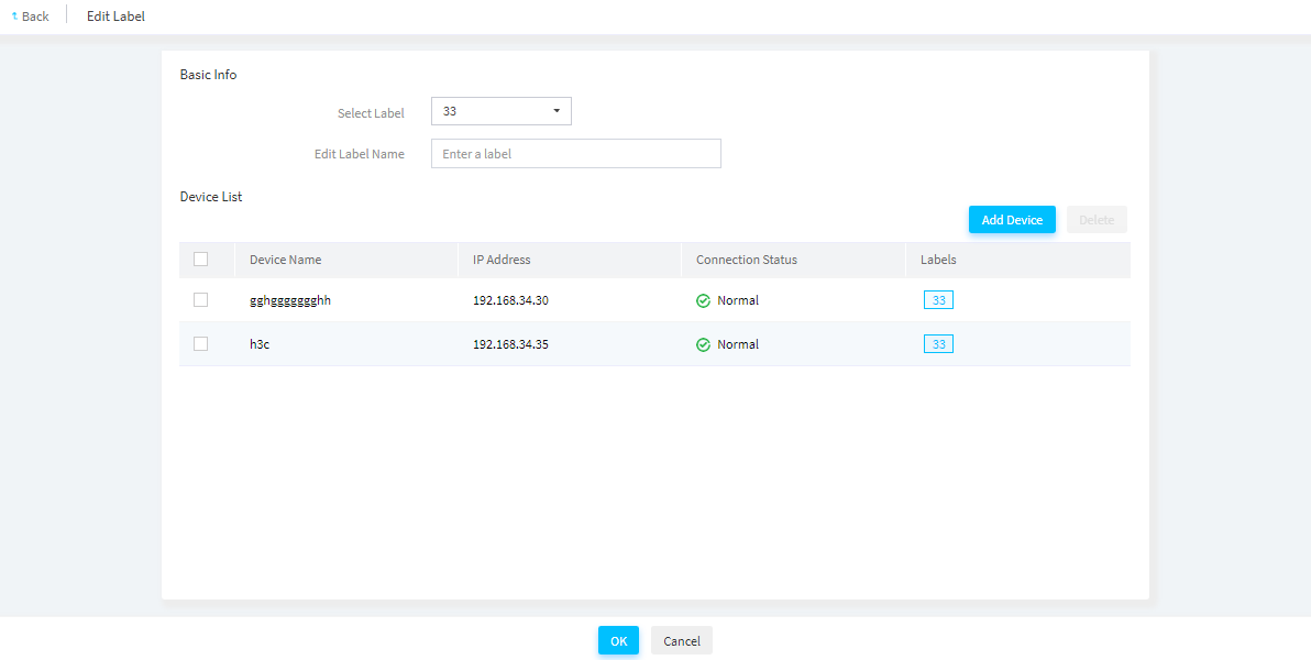
Delete switch labels
1. In the navigation pane, select Menu > Devices > Switch List.
2. Click Labels. Click Delete Label.
3. In the dialog box that opens, select the labels to delete and click OK.
Manage templates
Manage enclosure templates
From the Templates > Enclosure Templates page, you can add, copy, delete, edit, and view enclosure templates.
In an enclosure template, you can bind server templates to blade server slots in an enclosure. Then, you can apply the enclosure template to selected enclosures. For more information about applying enclosure templates, see "Apply enclosure templates."
View enclosure template information
About this task
Perform this task to view the enclosure template list and detailed information about an enclosure.
Procedure
1. In the navigation pane, select Menu > Templates > Enclosure Templates.
Figure 80 Enclosure template list
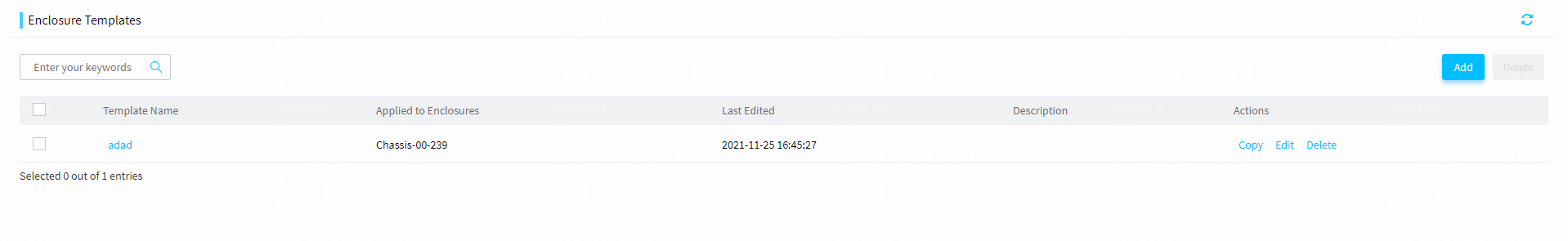
2. To view detailed information about an enclosure template, click the name of the template.
Add an enclosure template
Procedure
1. In the navigation pane, select Menu > Templates > Enclosure Templates.
2. Click Add.
3. In the Basic Info area, enter the template name and description (optional).
4. In the Blade Server-to-Template Bindings area, select the server template to bind to each blade server slot. For information about configuring a server template, see "Manage server templates."
5. Click OK.
Figure 81 Adding a server template
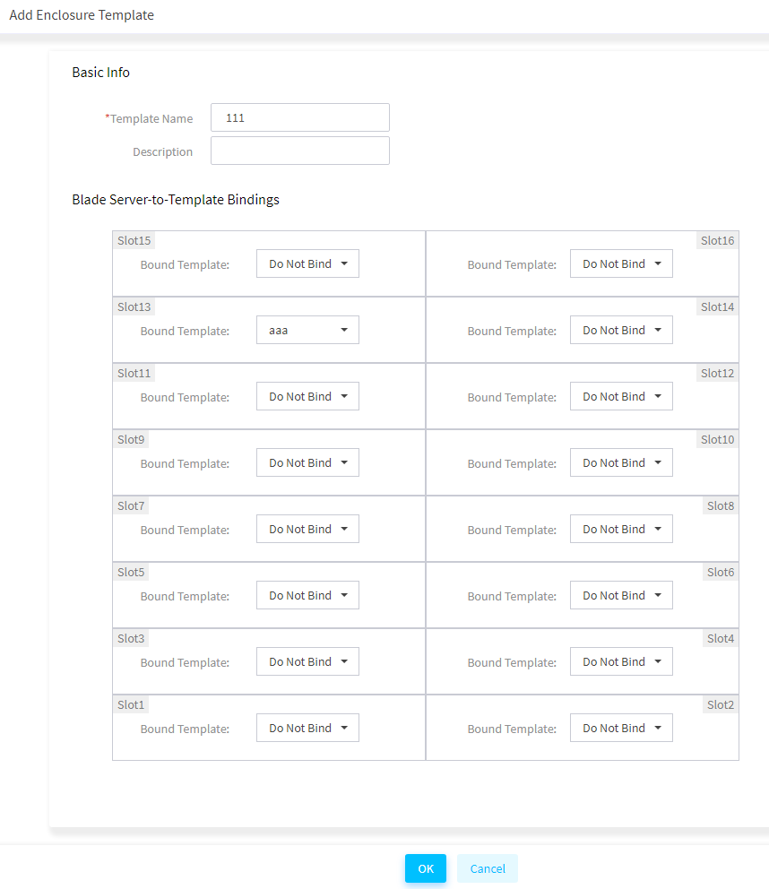
Delete enclosure templates
1. In the navigation pane, select Menu > Templates > Enclosure Templates.
2. Perform either of the following steps:
¡ To bulk delete enclosure templates, select the target templates and click Delete.
¡ To delete a single enclosure template, click Delete in the Actions column for the template.
3. In the dialog box that opens, click OK to confirm the operation.
Copy an enclosure template
1. In the navigation pane, select Menu > Templates > Enclosure Templates.
2. Click Copy in the Actions column for the template to be copied.
3. Specify a name for the new template, and then edit the template settings as needed.
4. Click OK.
Edit an enclosure template
1. In the navigation pane, select Menu > Templates > Enclosure Templates.
2. Click Edit in the Actions column for the template to be edited.
3. Edit the template settings.
4. Click OK.
Manage server templates
From the Templates > Server Templates page, you can add, copy, delete, edit, and view server templates.
In a server template, you can define HDM, BIOS, HDM online, connection, RAID, and OS installation settings for servers. Then, you can bulk apply the template settings to servers by applying the server template to servers. For more information about applying server templates, see "Apply server templates."
Add a server template
About this task
You can add a server template in one of the following methods:
· Add a new server template: Add a server template on the Add Server Template page.
· Copy and modify an existing server template: Copy and modify an existing server template to generate a new server template.
Procedure
1. In the navigation pane, select Menu > Templates > Server Templates to enter the Server Templates page as shown in Figure 82.
Figure 82 Server Templates page
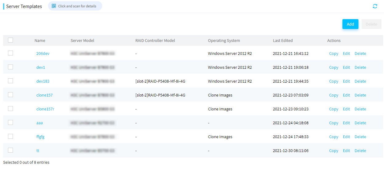
2. Click Add to enter the page as shown in Figure 83.
Figure 83 Adding a server template
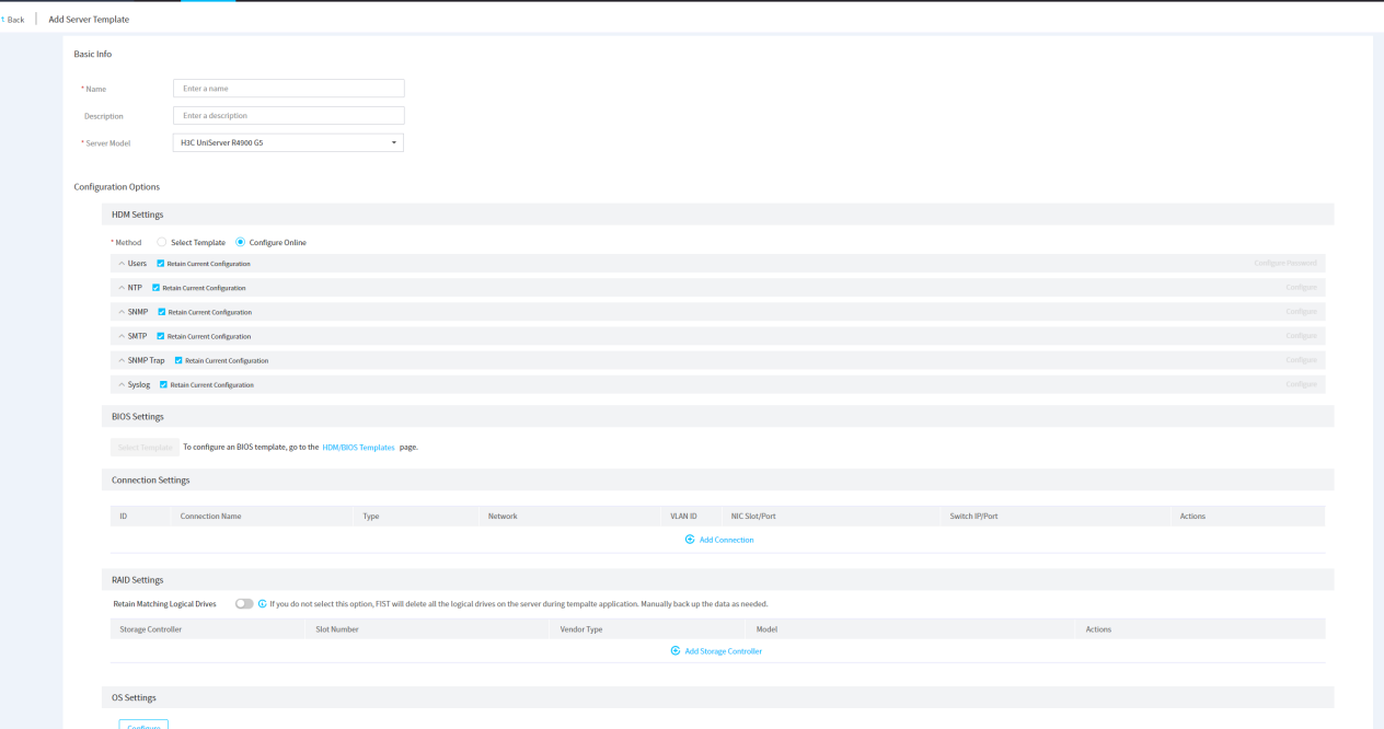
3. (Optional.) To create a server template based on an existing template, click Copy in the Actions column for the server template.
4. In the Basic Info area, enter the server template name and template description (optional), and select a compatible server model from the Server Model list.
5. Configure HDM Settings, BIOS Settings, Connection Settings, RAID Settings, and OS Settings. For more information, see the following sections.
6. To view details of a server template, click the name of the server template. If the method Use Answer File is selected for the server template in the OS settings, click Download File to download and view the answer file.
Configure HDM/BIOS templates
About this task
In a server template, you can select an exported HDM or BIOS configuration template file. Then, you can save the configuration template file in the server template and bulk apply the template to multiple servers. In this way, you can configure HDM settings and BIOS settings for multiple servers at the same time.
FIST allows you to export HDM settings or BIOS settings into a configuration template file. For more information, see "Configure HDM/BIOS templates."
Restrictions and guidelines
· Before applying HDM or BIOS settings to servers, make sure the HDM or BIOS of the target servers operates properly.
· Before applying an HDM template to servers, make sure the server model, HDM version, and hardware configuration of the target servers are the same as those in the HDM template.
· Before applying a BIOS template to servers, make sure the server model and BIOS version of the target servers are the same as those in the BIOS template. BIOS settings applied to a server take effect after the server is rebooted.
· After the HDM settings are successfully applied to a server, HDM of the server will automatically reboot. The HDM IP might change. If the HDM IP changes, the whole server template application process will end in advance. In this case, view the current HDM IP and add the HDM to FIST again.
Procedure
1. In the navigation pane, select Menu > Templates > Server Templates.
2. Click Add.
3. (Optional.) To configure the HDM or BIOS templates, click the HDM/BIOS Templates link.
4. Click Select Template in the HDM Settings or BIOS Settings area (the HDM Settings area in this example), select an exported HDM template, and click OK.
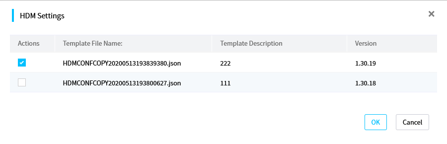
Configure HDM online
About this task
This task allows you to configure HDM online, including user, NTP, SNMP, SNMP Trap, and Syslog settings.
Procedure
1. Configure users:
|
|
IMPORTANT: Changing the default password (Password@_) of user admin might cause HDM connection errors. Please be cautious. |
a. Unselect Retain Current Configuration from the Users field.
b. Click Configure Password, and then configure the password policy.
- Enable or disable password complexity check.
- Specify password settings, such as password validity.
- Click OK.
Figure 85 Configuring the password policy
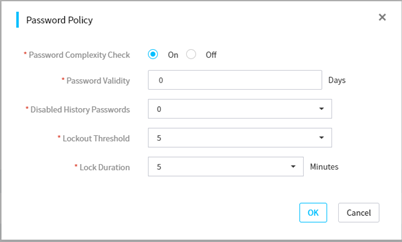
c. Click Add User, configure user settings, and then click OK.
Figure 86 Adding a user
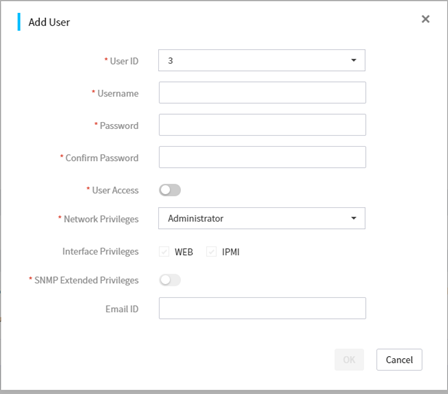
d. Click Edit for a user entry, configure user settings, and then click OK.
Figure 87 Editing a user
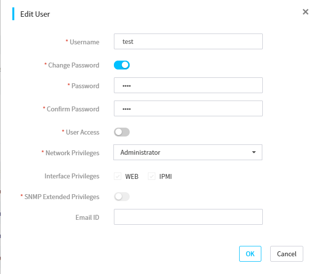
2. Configure NTP:
a. Unselect Retain Current Configuration from the NTP field.
b. Click Configure and then configure NTP:
- Enable or disable auto synchronization. This feature enables the system to synchronize time settings from the NTP server.
- Set the synchronization interval, and specify the primary, secondary, and tertiary NTP servers.
- Click OK.
Figure 88 Configuring NTP
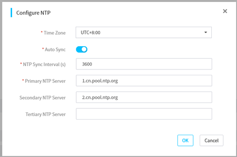
3. Configure SNMP:
a. Unselect Retain Current Configuration from the SNMP field.
b. Click Configure and then configure SNMP:
- Select the SNMP version.
- Select whether to enable the long community string feature.
- Select Read-Only Community String or Read/Write Community String and specify the string.
- Click OK.
Figure 89 Configuring SNMP
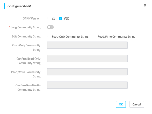
4. Configure SMTP:
a. Unselect Retain Current Configuration from the SMTP field.
b. Click Configure and then configure SNMP:
- Enable SMTP.
- Specify the SMTP server address and server port.
- Select whether to enable anonymous email. To send alert emails as anonymous emails, enable this feature. To send alert emails with sender identity information, disable this feature and enter the username and password for connecting to the SMTP server. The username is a string of 1 to 255 characters.
- Specify the sender email address. Make sure the email service uses the SMTP mail server.
- Select the severity levels. Options include Critical, Minor + Major + Critical, and All.
- Select email subjects. Options include Product Name, Host Name, Asset Tag, and System Board Serial Number. This field is available only for G6 servers.
- Click OK.
Figure 90 Configuring SMTP
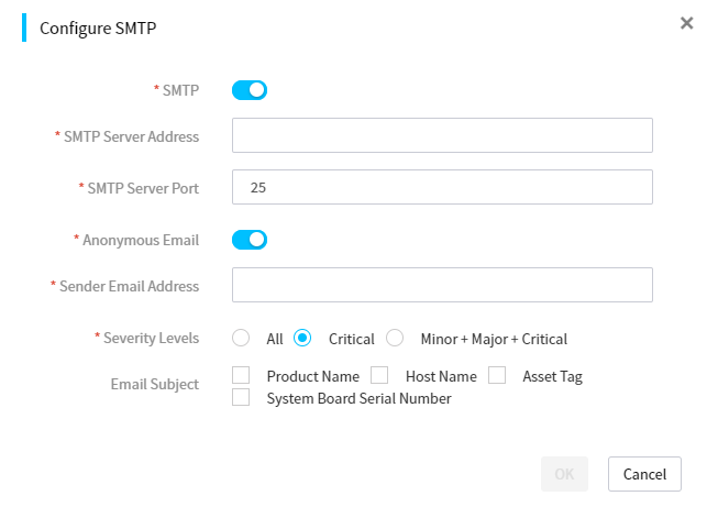
c. Click Add Email Address, and then configure recipient information:
- Select the username of the recipient. The email address of the user is automatically populated. This is available only for non-G6 servers.
- Enter the email subject. The subject is a string of 1 to 255 characters.
- Click OK.
Figure 91 Adding an email recipient
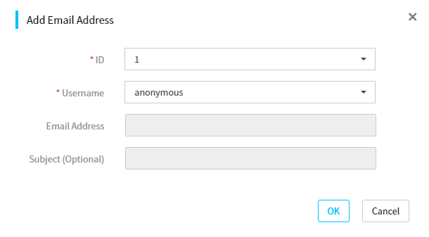
5. Configure SNMP Trap:
a. Unselect Retain Current Configuration from the SNMP Trap field.
b. Click Configure and then configure SNMP:
- Enable SNMP Trap.
- Select the SNMP Trap mode. Options include Node OID, Event OID, and Event code OID (only for G6 servers).
- Select the SNMP Trap version. If SNMPv3 is selected, you must also specify an SNMPv3 user.
- (Optional.) Enter the location of the server and contact information.
- Specify the community string and select the alarm severity levels.
- Click OK.
Figure 92 Configuring SNMP Trap
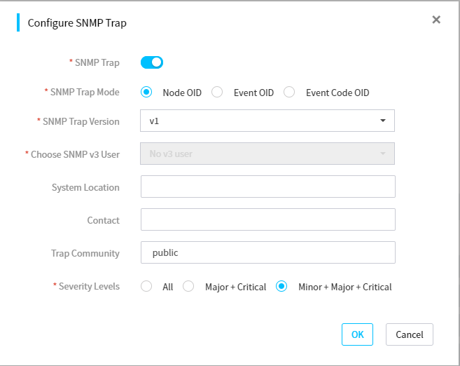
c. Click Add SNMP Trap Server, and then configure the SNMP Trap server:
- Select a server number.
- Select whether to enable the server.
- (Optional.) Specify the server address.
- Specify the port number.
- Click OK.
Figure 93 Adding an SNMP Trap server
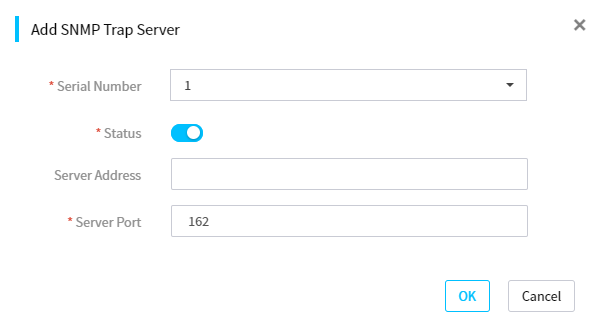
6. Configure Syslog:
|
|
NOTE: When you configure syslog settings, note that the Product serial number option is available in the Alarm log host ID field only in HDM version 2.80 and later. |
a. Unselect Retain Current Configuration from the Syslog field.
b. Click Configure and then configure SNMP.
Alarm Log Notification
- Enable log notification.
- Select an alarm log host ID, and select a transmission protocol.
- Select the log format. Options include Simplified, RFC3164, and RFC5424. This field is available only for G6 servers.
If you select the Simplified format, you must configure the custom log format. Options include Timestamp, Host Name, and Message,. The Message option is selected by default. This field is available only for G6 servers.
SDR Information Settings (non-G6 servers)
- Enable SDR remote information.
- Select a transmission protocol.
- Enter the server address, port number, and interval.
Host Serial Port Settings (non-G6 servers)
- Enable serial port information.
- Select a transmission protocol.
- Specify the server address and port number.
- Click OK.
Figure 94 Configuring Syslog

c. Click Add Alarm Log Server and then configure the alarm log server.
- Select a number.
- Select the server state.
- Enter the server name. This field is available only for G6 servers.
- Enter the server address and port number.
- Select the log type.
- Select the log severity. This field is available only for G6 servers.
- Click OK.
Figure 95 Adding an alarm log server

Configure the BIOS online
This task allows you to configure the BIOS online. Only the R4900 G3, R4900 G5, B5700 G5, R4700 G5, R6900 G5, and R5300 G5 servers support this feature. For the R4900 G3, this feature is available in BIOS 2.58 and later versions. For the R4900 G5, B5700 G5, R4700 G5, R6900 G5, and R5300 G5, this feature is available in BIOS 5.45 and later versions.
The BIOS options available for online configuration vary by device model. For more information, see the BIOS user guide for the device.
Figure 96 Configuring the BIOS online
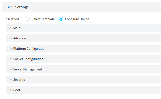
Configure connection settings
About this task
In a server template, you can define switch port-to-server port connections and assign a network to each connection. Then, you can bind the server template to the corresponding switch ports by using the auto-configuration feature to enable automated network configuration of the switch ports.
Restrictions and guidelines
The connection settings in a server template can be applied only to ports on an H3C S6850-56HF or H3C S6800-54QF switch.
A switch port will be configured as an access port after the connection settings are applied to the port.
Procedure
The configuration procedure varies by server model. This section describes these configuration procedures separately.
Add connection
1. In the navigation pane, select Menu > Templates > Server Templates.
2. Click Add to open the page for adding a server template.
3. In the Connection Settings area, click Add Connection for rack servers. In the dialog box that opens, configure the following parameters:
a. Enter a connection name in the Connection Name field.
b. Select an existing network from the Network list. For information about creating networks in FIST, see "Manage networks."
c. Select the NIC slot and NIC port at the server end of the connection. The HDM dedicated network port cannot be selected.
The NIC slot and NIC port settings are intended only for reference by the server administrator during network planning. The settings will not be directly applied to the actual server in the template application process.
d. Select the switch IP address and switch port at the switch end of the connection. The switch must have been added to FIST. For more information, see "Add a switch."
A template with a connection added can be applied only to one device.
4. Click OK to add the connection.
Figure 97 Adding a connection
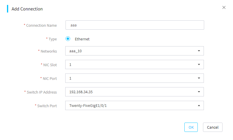
Add Mezz card
1. In the Connection Settings area, click Add Mezzanine Card for G3 blade servers. You can repeat the following steps to add multiple Mezzanine cards.
2. Select the slot number and type for a Mezzanine card.
3. Click Configure Port in the Actions column. In the dialog box that opens, configure ports as needed, as shown in Figure 98.
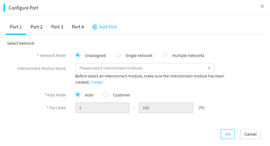
4. Select a network mode. If you select Multiple networks, you must set the server VLAN ID.
5. Select a created interconnect module template. For information about creating an interconnect module template, see "Manage interconnect module templates."
6. Select a rate mode and set a port rate.
7. Click OK.
Configure RAID configuration templates
About this task
Through preconfiguring a RAID configuration template, you can bulk configure RAID settings for servers.
Supported storage controllers
· HBA-1000-M2-1(RAID (Hide RAW) mode only)
· HBA-H460-B1
· HBA-H460-M1
· HBA-H5408-Mf-8i
· HBA-LSI-9440-8i
· RAID-L460-M4 (RAID mode only)
· HBA-LSI-9311-8i-A1-X
· RAID-LSI-9361-8i(1G)-A1-X
· RAID-LSI-9361-8i(2G)-1-X
· RAID-LSI-9460-16i(4G)
· RAID-LSI-9460-8i(4G)
· RAID-LSI-9460-8i(2G)
· HBA-LSI-9540-LP-8i
· RAID-LSI-9560-LP-8i-4GB
· RAID-LSI-9560-LP-16i-8GB
· RAID-P2404-Mf-4i-2GB
· RAID-P430-M1 (RAID (Hide RAW) mode and RAID (Expose RAW) mode)
· RAID-P430-M2 (RAID (Hide RAW) mode and RAID (Expose RAW) mode)
· RAID-P460-B2
· RAID-P460-B4
· RAID-P460-M2
· RAID-P460-M4
· RAID-P4408-Mf-8i-2GB
· RAID-P4408-Ma-8i-2GB
· RAID-P5408-Mf-8i-4GB
· RAID-P5408-Ma-8i-4GB
Restrictions and guidelines
· Make sure the storage controllers to be configured are of the same model as those specified in the RAID settings. If two storage controllers are specified in the RAID settings, make sure the corresponding slots have storage controllers of the matching models on the servers to be configured.
· Make sure the RAID member drives are present and operating properly.
Procedure
1. In the navigation pane, select Menu > Templates > Server Templates.
2. Click Add.
3. In the Basic Info area, set the parameters.
4. As shown in Figure 99, select whether to enable Retain Matching Logical Drives in the RAID Settings area. If you enable this option to retain a logical drive on a server, make sure the logical drive's member drives and RAID level match those of a logical drive configured in this area. If you do not enable this option, FIST will delete the existing logical drives on a server.
|
|
NOTE: · After you enable Retain Matching Logical Drives, FIST will retain a logical drive on a server if the logical drive's member drives and RAID level match those of a logical drive configured in this area. FIST will not modify the retained logical drives. For example, if the RAID name in the configuration file for a retained logical drive is different from the actual RAID name, FIST will not modify the RAID name of the retained logical drive. · To install an operating system to a retained logical drive, make sure the RAID name of the target drive in the OS settings area is the same as the original RAID name of the retained logical drive. |
5. Click Add Storage Controller. Select a storage controller model.
Figure 99 Adding a storage controller
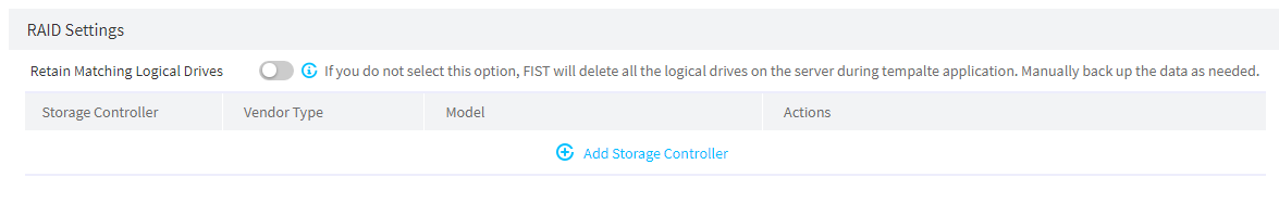
6. As shown in Figure 100, select values from the Slot Number, Vendor Type, and Model lists. The Slot Number list is available only when the selected server model supports multiple storage controllers. Click Configure to configure a logical drive.
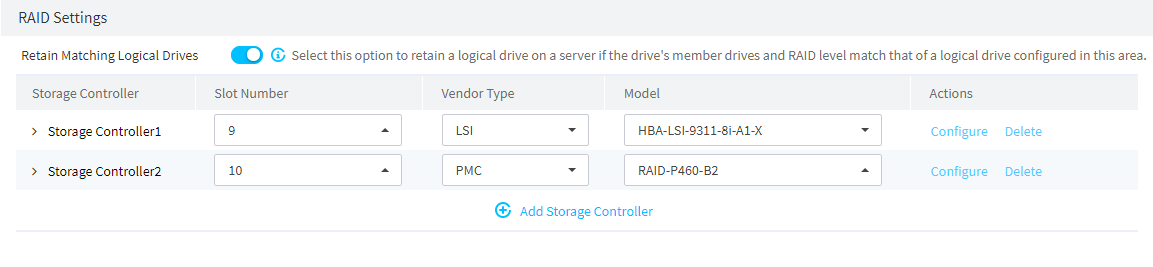
7. In the dialog box that opens as shown in Figure 101, click Add Logical Drive.
8. Enter the RAID name, and select the RAID level and physical drives.
9. Click OK.
Figure 101 Storage controller settings
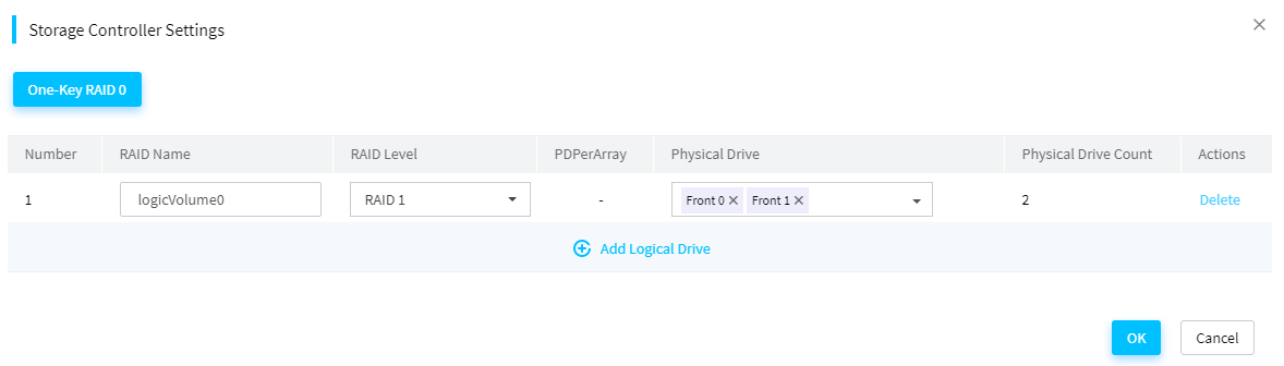
Table 10 Parameters for RAID settings
|
Parameter |
Remarks |
|
One-Key RAID 0 |
Select this option to use the remaining physical drives that have not been added to any RAID array to create RAID 0 or simple volume. Some storage controllers do not support the One-Key RAID 0 option. |
|
RAID Name |
Name of the RAID array (logical drive) to create. On the same storage controller, the RAID names must be unique. |
|
RAID Level |
Level of the logical drive to create. The available RAID levels depend on the storage controller model, as shown in Table 4. The other available storage controllers that are not listed in Table 4 support RAID 0, RAID 1, RAID 5, RAID 6, RAID 10, and RAID 50. |
|
Physical Drive |
Physical drives used to create the logical drive. |
|
PDPerArray |
Number of physical drives per sub RAID array. This parameter is required only for a RAID 50 array on an LSI controller. |
Table 11 RAID levels supported by storage controllers
|
Storage controller |
RAID levels |
|
HBA-1000-M2-1 |
RAID 0, RAID 1, and RAID 10 |
|
HBA-H460-B1 HBA-H460-M1 |
RAID 0, RAID 1, RAID 5, and RAID 10 |
|
HBA-H5408-Mf-8i |
RAID 0, RAID 1, and RAID 10 |
|
HBA-LSI-9311-8i-A1-X |
RAID 0, RAID 1, and RAID 10 |
|
RAID-P430-M1 RAID-P430-M2 |
RAID 0, RAID 1, RAID 5, RAID 6, RAID 10, RAID 50, and Simple Volume |
|
HBA-LSI-9440-8i |
RAID 0, RAID 1, RAID 5, RAID 10, and RAID 50 |
|
HBA-LSI-9540-LP-8i |
RAID 0, RAID 1, and RAID 10 |
Configure OS settings
About this task
Perform this task to create the configuration templates for OS installation. When you configure the OS installation template, you must configure the OS information, which supports the exported OSs for cloning, Linux operating systems, Windows operating systems, and VMware operating systems.
To successfully apply a server template for OS installation, you must upload the OS image files on the Menu > Templates > Images page.
Supported operating systems
A server template supports installing the Red Hat Enterprise Linux, SUSE Linux Enterprise Server, CentOS, Oracle Linux, Ubuntu Server, VMware ESXi, and Windows Server operating systems (excluding the core versions). For more information, see Table 5.
Table 12 Supported operating systems
|
OS type |
Versions |
|
Images imported for OS cloning |
For the operating systems supported by OS cloning, see "Clone images." |
|
CentOS |
CentOS 6.10 (64 bit) |
|
CentOS 7.3 (64 bit) |
|
|
CentOS 7.4 (64 bit) |
|
|
CentOS 7.5 (64 bit) |
|
|
CentOS 7.6 (64 bit) |
|
|
CentOS 7.7 (64 bit) |
|
|
CentOS 7.8 (64 bit) |
|
|
CentOS 7.9 (64 bit) |
|
|
CentOS 8.0 (64 bit) |
|
|
CentOS 8.1 (64 bit) |
|
|
CentOS 8.2 (64 bit) |
|
|
CentOS 8.3 (64 bit) |
|
|
CentOS 8.4 (64 bit) |
|
|
Red Hat Enterprise Linux |
Red Hat Enterprise Linux 6.7 (64 bit) (includes KVM) |
|
Red Hat Enterprise Linux 6.8 (64 bit) (includes KVM) |
|
|
Red Hat Enterprise Linux 6.9 (64 bit) (includes KVM) |
|
|
Red Hat Enterprise Linux 6.10 (64 bit) (includes KVM) |
|
|
Red Hat Enterprise Linux 7.2 (64 bit) (includes KVM) |
|
|
Red Hat Enterprise Linux 7.3 (64 bit) (includes KVM) |
|
|
Red Hat Enterprise Linux 7.4 (64 bit) (includes KVM) |
|
|
Red Hat Enterprise Linux 7.5 (64 bit) (includes KVM) |
|
|
Red Hat Enterprise Linux 7.6 (64 bit) (includes KVM) |
|
|
Red Hat Enterprise Linux 7.7 (64 bit) (includes KVM) |
|
|
Red Hat Enterprise Linux 7.8 (64 bit) (includes KVM) |
|
|
Red Hat Enterprise Linux 7.9 (64 bit) (includes KVM) |
|
|
Red Hat Enterprise Linux 8.0 (64 bit) (includes KVM) |
|
|
Red Hat Enterprise Linux 8.1 (64 bit) (includes KVM) |
|
|
Red Hat Enterprise Linux 8.2 (64 bit) (includes KVM) |
|
|
Red Hat Enterprise Linux 8.3 (64 bit) (includes KVM) |
|
|
Red Hat Enterprise Linux 8.4 (64 bit) (includes KVM) |
|
|
Red Hat Enterprise Linux 8.6 (64 bit) (includes KVM) |
|
|
SUSE Linux Enterprise Server |
SLES 11 SP4 (64 bit) (includes XEN & KVM) |
|
SLES 12 (64 bit) SP1 (includes XEN & KVM) |
|
|
SLES 12 (64 bit) SP2 (includes XEN & KVM) |
|
|
SLES 12 (64 bit) SP3 (includes XEN & KVM) |
|
|
SLES 12 (64 bit) SP4 (includes XEN & KVM) |
|
|
SLES 12 (64 bit) SP5 (includes XEN & KVM) |
|
|
SLES 15 (64 bit) (includes XEN & KVM) |
|
|
SLES 15 (64 bit) SP1 (includes XEN & KVM) |
|
|
Ubuntu Server |
Ubuntu Server 17.10 (64 bit) – LTS |
|
Ubuntu Server 17.10.1 (64 bit) – LTS |
|
|
Ubuntu Server 18.04 (64 bit) – LTS |
|
|
Ubuntu Server 18.04.1 (64 bit) – LTS |
|
|
Ubuntu Server 18.04.2 (64 bit) – LTS |
|
|
Ubuntu Server 18.04.3 (64 bit) – LTS |
|
|
CAS |
CAS 5.0 E0513 |
|
CAS 5.0 E0526 |
|
|
Oracle Linux 8.2 |
Oracle Linux 8.2 |
|
VMware ESXi |
VMware ESXi 6.5 U1 (64 bit) |
|
VMware ESXi 6.5 U2 (64 bit) |
|
|
VMware ESXi 6.5 U3 (64 bit) |
|
|
VMware ESXi 6.7 (64 bit) |
|
|
VMware ESXi 6.7 U3 (64 bit) |
|
|
VMware ESXi 7.0 (64 bit) |
|
|
Windows Server |
Microsoft Hyper-V Server 2012 R2 |
|
Microsoft Hyper-V Server 2016 |
|
|
Microsoft Hyper-V Server 2019 |
|
|
Microsoft Windows Server 2012 R2 |
|
|
Microsoft Windows Server 2016 |
|
|
Microsoft Windows Server 2019 |
|
|
Microsoft Windows Server 2012 R2 Standard |
|
|
Microsoft Windows Server 2012 R2 Datacenter |
|
|
Microsoft Windows Server 2012 R2 Essentials |
|
|
Microsoft Windows Server 2016 Essential |
|
|
Microsoft Windows Server 2016 Standard |
|
|
Microsoft Windows Server 2016 Datacenter |
|
|
Microsoft Windows Server 2019 Standard |
|
|
Microsoft Windows Server 2019 Datacenter |
Prerequisites
· Make sure the OS image file exists and contains the same OS as the server template.
· To install the Windows operating system, make sure the capacity of the target drive meets the primary partition requirements of the server template.
Procedure
1. In the OS Settings area on the page, click Configure.
2. (Optional.) As shown in Figure 102, when you select a RedHat or CentOS operating system, you can select the Use Answer File method. Click Download Template to obtain the answer file template for the system. Modify the answer file template as needed, and click the … icon next to Answer File to upload the answer file.
|
|
NOTE: If you select the Use Answer File method in the OS Settings area, click Download Template to obtain the answer file template for the system. If you completely self-define an answer file, the server template fails to be created. For the answer file format and usage, see the guidelines and the readme file in the template. |
Figure 102 Using an answer file
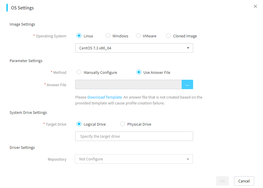
Table 13 Parameters for using an answer file
|
Parameter |
Remarks |
|
Answer File |
The operating system will be automatically installed according to the answer file. You can customize the answer file according to the downloaded template file. (This option is applicable to only the custom settings.) |
3. Configure OS-related parameters. The available parameters vary by OS type, as shown in Figure 103, Figure 104, and Figure 105. If necessary, you can select drivers to be installed from the repository. When installing an operating system on a server. iFIST will also automatically install its built-in drivers required by the operating system. For information about iFIST built-in drivers, see iFIST User Guide.
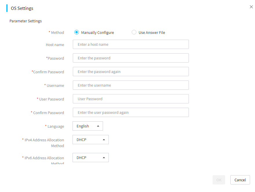
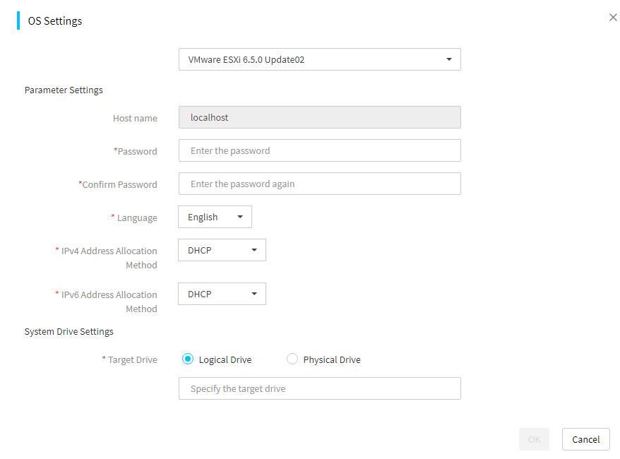
Table 14 Parameters for OS settings
|
Parameter |
Remarks |
|
Operating System |
Select the operating system type and operating system name. The OS Settings page varies by the selected operating system type. |
|
(Optional.) Host Name |
Name of the host where the operating system is to be installed. You can select a host name range in a host name pool. For more information about host name pools, see "Manage host name pools." The default host name for the Linux operating system is localhost. If you select DHCP as the IPv4 address allocation method for a VMware ESXi operating system, the Host Name field is unavailable. If you select Cloned Image for the operating system field, the default host name uses the host name in the source operating system. |
|
Password |
Password for logging in to the system. If you select a Linux operating system, the password is the root password. |
|
Username |
Username of a non-root user. NOTE: · This option is applicable only to the Linux operating system. · This option is not applicable to the VMware ESXi or CAS operating system. · When you configure a username in the Ubuntu system, do not use a reserved username of the Ubuntu system, for example, root and admin. |
|
User Password |
Password of a non-root user for logging in to the system. This option is applicable only to the Linux operating system. This option is not applicable to the VMware ESXi or CAS operating system. |
|
Language |
Language of the operating system: · Simplified Chinese. · English. NOTE: This option is not applicable to the VMware ESXi or CAS operating system. |
|
IPv4 Address Allocation Method |
Options are DHCP and Static. If you select Static, you must select an address range in an IPv4 address pool. For more information about IPv4 address pools, see "Manage IPv4 address pools." NOTE: The CAS operating system does not support DHCP. |
|
IPv6 Address Allocation Method |
Options are DHCP and Static. If you select Static, you must select an address range in an IPv6 address pool. For more information about IPv6 address pools, see "Manage IPv6 address pools." NOTE: · The VMware ESXi operating system supports only the DHCP method. · The CAS operating system does not support IPv6. · The Ubuntu Server operating system does not support IPv6 when IPv4 Address Allocation Method is set to Static, and it does not support IPv4 when IPv6 Address Allocation Method is set to Static. |
|
Target Drive |
Drive where the operating system is to be installed. |
|
Repository |
Select a repository. Available options are repositories in the repository library. When an inventoried repository is selected, the list will display the drivers applicable to the operating system selected on the OS Settings page. |
Figure 105 Windows OS settings
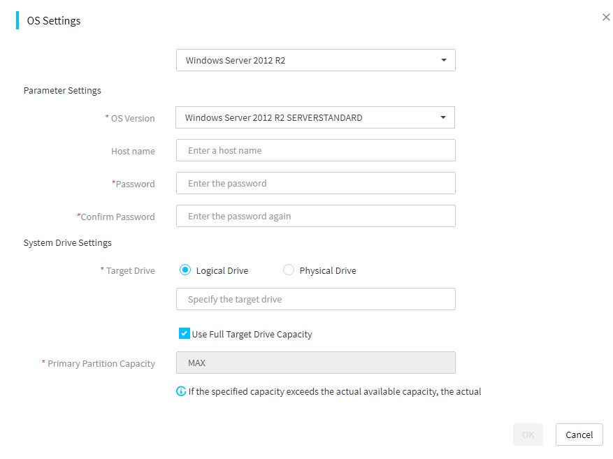
Table 15 Parameters for Windows OS settings
|
Parameter |
Remarks |
|
OS Version |
Select an OS version. (This option is applicable only to an operating system that supports multiple versions.) |
|
(Optional.) Host Name |
Name of the host where the operating system is to be installed. If this filed is left empty in the Windows operating system, the Windows operating system automatically assigns a host name. |
|
Primary Partition Capacity |
Capacity of the system partition where the operating system is to be installed, in the range of 51200 to 10485760 MB. If you select Use Full Logical Drive Capacity, the primary partition capacity is set to the maximum value available. To successfully install the operating system, make sure the capacity is no smaller than 50 GB. When the physical drive capacity is large, as a best practice, set the primary partition capacity to the maximum value. (This option is applicable only to the Windows operating systems. In the Linux operating systems, the primary partition capacity is not displayed and uses the maximum available value by default, and the minimum required drive capacity is 80 GB.) |
Configure HDM/BIOS templates
About this task
Perform this task to export the HDM/BIOS settings of a server to generate a configuration template file. Then, you can apply the configuration template file to the specified servers. This feature allows you to copy or configure HDM settings and BIOS settings for multiple servers at the same time. You can also use the configuration template file to back up the current settings of the server.
This feature depends on the HDM interface. The HDM settings imported to servers take effect after the HDMs are rebooted. The BIOS settings imported to servers take effect after the servers are rebooted.
Prerequisites
To use this feature, you must add HDM server nodes to FIST first. For more information, see "Add, edit, or delete servers."
Export HDM/BIOS settings
Prerequisites
· Before exporting the settings of a server, make sure the HDM or BIOS of the server operates properly.
· The privilege to export settings depends on the network privilege of the HDM account. Make sure the user has the privilege to this operation.
· During the export process, do not switch to another page, refresh the page, or execute other configuration management operations.
· Up to 40 HDM/BIOS configuration template files can be saved. If the upper limit has been reached, manually delete the configuration template files that are not frequently used.
Procedure
1. Click HDM Settings or BIOS Settings in the Export column for the managed server, as shown in Figure 106.
To quickly filter out the target server, you can use the label or enter a keyword in the search area.
Figure 106 HDM/BIOS configuration templates
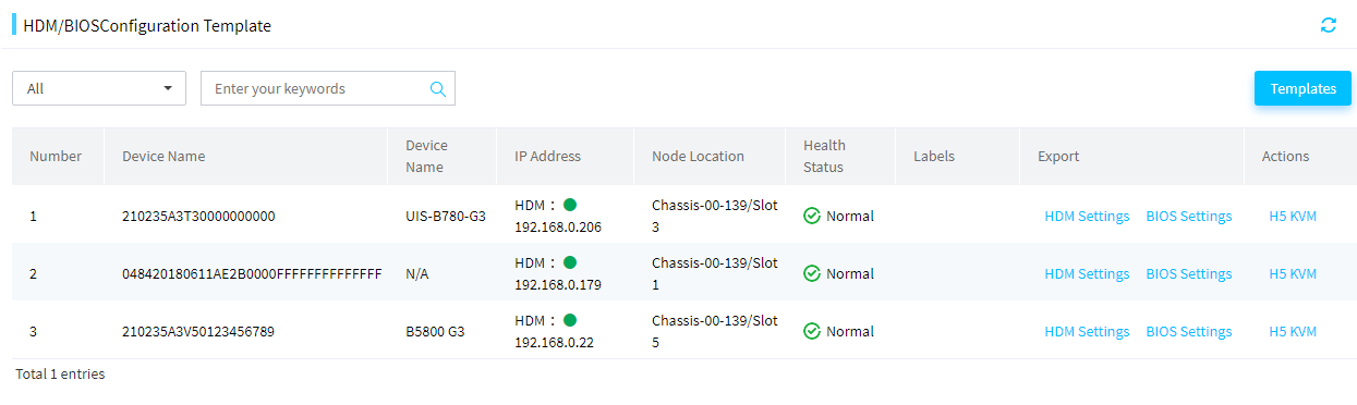
2. In the dialog box that opens, enter the template description (optional).
3. Click OK to start exporting the settings. The template file generated is automatically named [HDM/BIOS]CONFCOPY+time when the configuration was exported.json.
Manage templates
About this task
Perform this task to delete, download, and upload configuration templates.
Procedure
1. In the navigation pane, select Menu > Templates > HDM/BIOS Templates.
2. Click Templates to enter the template management page, as shown in Figure 107.
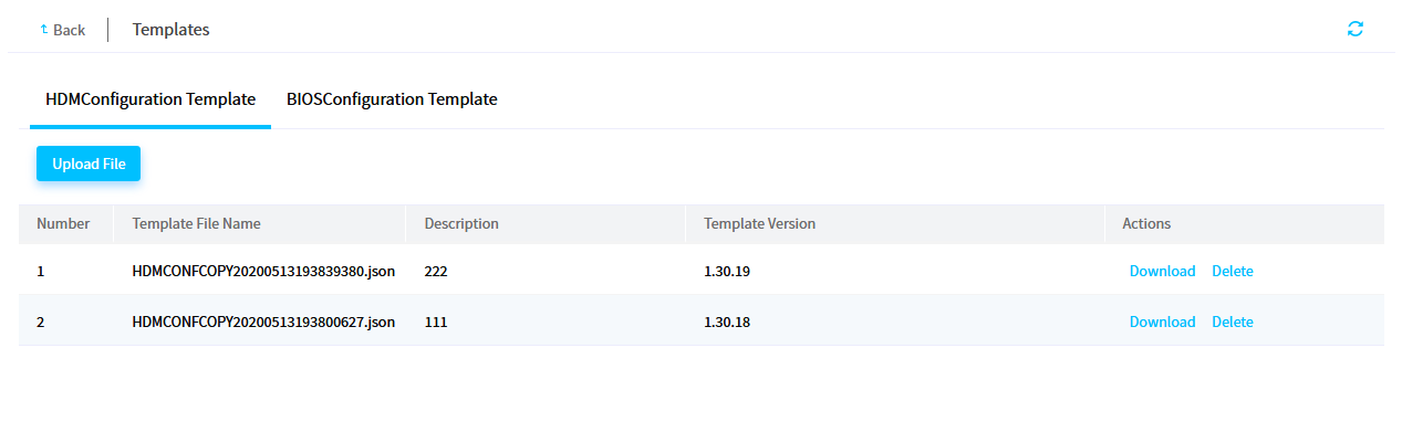
3. Click the HDM Templates or BIOS Templates tab.
4. Click Upload File.
5. In the dialog box that opens, click the … icon for the Upload File field, and select the configuration file to upload.
6. (Optional.) Enter the template description.
7. Click OK.
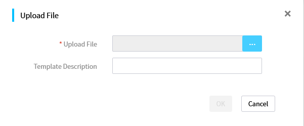
8. (Optional.) To download a configuration template file, click Download for the template to download, select the path to save the configuration template file, and click OK.
9. (Optional.) To delete a configuration template file, click Delete for the template to delete. In the dialog box that opens, click OK.
Configure repositories
About this task
From this menu, you can add, edit, delete, inventory, and customize repositories.
A repository is a compressed file containing various drivers for various optional cards and the system board and containing firmware for various HDM, BIOS, CPLD, drives, and optional cards. The firmware and drivers are collectively referred to as components.
By using this feature together with the component update feature, you can bulk update the firmware and drivers for servers. For more information, see “Update components.”
|
|
IMPORTANT: To update drivers in the component update process, make sure the managed servers have FIST SMS installed. |
Network diagram
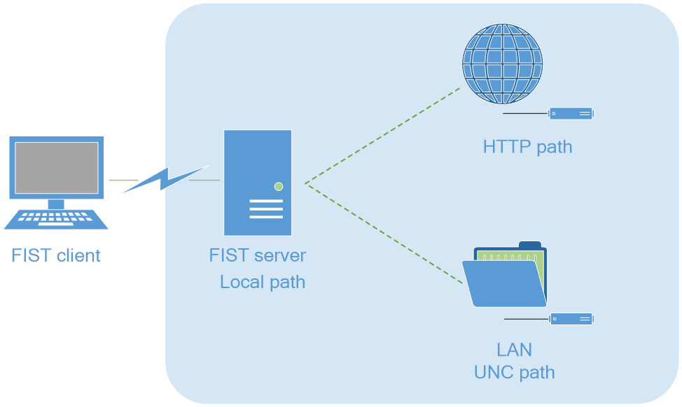
Add a repository
As of FIST 2.00.22, FIST will automatically inventory a repository after the repository is added.
Prerequisites
Prepare the repositories, and prepare the path types and paths for obtaining the repositories. The repository paths include three types, as shown in Table 9.
Table 16 Repository path types
|
Type |
Remarks |
|
UNC path |
Network path, through which you can obtain repository resources in a LAN through sharing resources. |
|
HTTP path |
HTTP server path, through which you can obtain repository resources on the specified HTTP server. |
|
Local path |
Local path, through which you can obtain repository resources on the FIST client. |
Procedure
1. In the navigation pane, select Menu > Templates > Repositories to enter the page as shown in Figure 110.
Figure 110 Repository management page
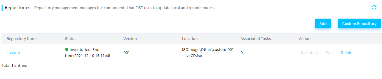
2. Click Add Repository. In the dialog box that opens, configure parameters as needed.
¡ If you select UNC Path as shown in Figure 111, you must enter the repository path, username, and password, and then click OK.
Figure 111 Adding a repository on an UNC path
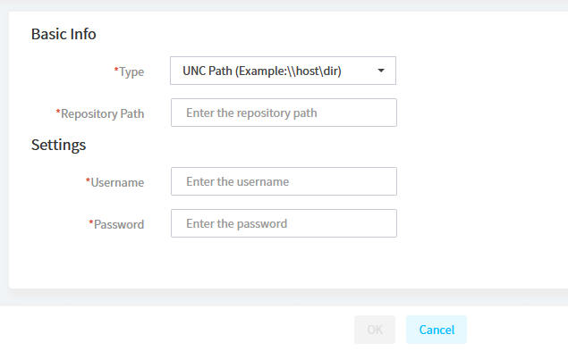
¡ If you select HTTP Path as shown in Figure 112, perform the following steps:
- Enter the repository path.
- To use the proxy to connect to an HTTP server, select Menu > System > Proxy Settings. For more information, see "Configuring proxy settings."
- Click OK.
Figure 112 HTTP path repository
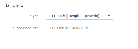
¡ If you select Local Path as shown in Figure 113, perform the following steps:
- Click Upload.
- In the dialog box that opens, select the repository file, and then click Upload.
Figure 113 Adding a repository on a local path
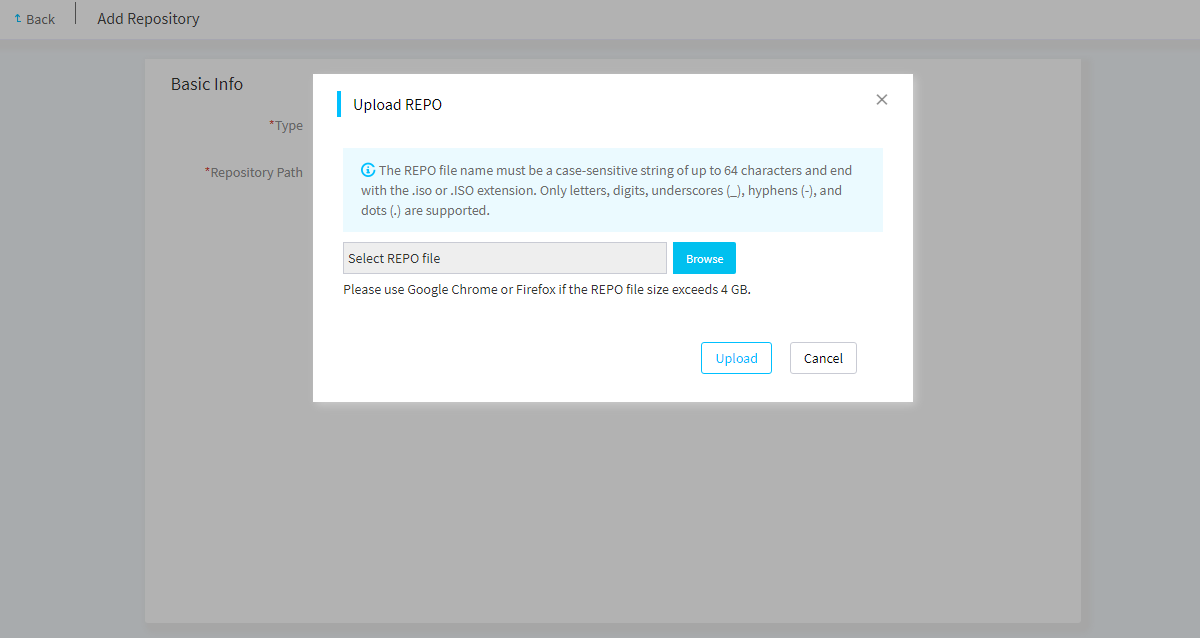
After you add a local repository to FIST, the repository list displays the newly added repository, and the repository will be automatically added to image list on the Menu > Templates > Images page.
Inventory a repository
About this task
Perform this task to list all components in a repository. After a repository is inventoried, its component list can display the corresponding components. In this case, the repository can be used properly.
Procedure
1. As shown in Figure 114, click Inventory in the Actions column for the repository that you want to inventory. Then, FIST will automatically inventory the selected repository.
Figure 114 Inventorying a repository
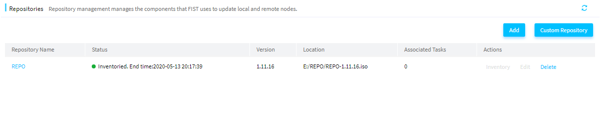
2. As shown in Figure 114, after inventorying is completed, the Status column for the repository displays Inventoried and the time when inventorying was completed.
3. Click the link in the Repository Name column for the target repository. The repository details page opens to display the repository information, as shown in Figure 115.
Figure 115 Repository Details

(Optional.) Create a custom repository or ISO file
About this task
Perform this task to select update packages for the specified components from the added and inventoried repositories and use them to create a custom repository or ISO file.
· After creating the custom repository, you can use it to upgrade components.
· After you create a custom ISO file, an ISO image file will be generated.
As of FIST 2.00.22, FIST will automatically inventory a custom repository after the custom repository is added.
Procedure
1. In the navigation pane, select Menu > Templates > Repositories to enter the repository management page.
2. Click Custom Repository. In the dialog box that opens, perform the following steps:
a. In the Basic Info area, enter the repository name and version, and then select Create ISO or Custom Repository for Build Type.
b. In the Source Repositories area, select the target repositories.
c. In the Filters area, select the target items, and then click Apply Filters to display the matching items.
d. In the component list, select the target components.
Figure 116 Creating a custom repository
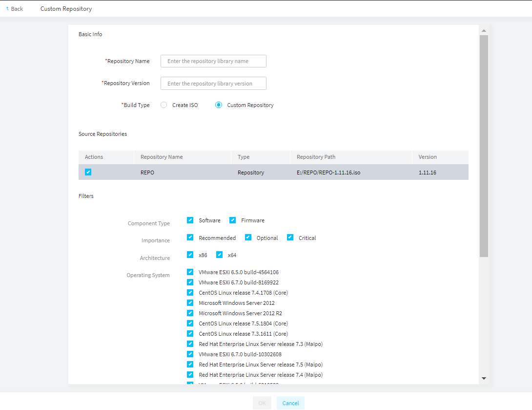
3. Click OK.
Edit a repository
About this task
Perform this task to edit a repository that has been added by a user but has not been inventoried. A custom repository, a local repository, or an inventoried repository cannot be edited. Depending on how a repository is added, you can perform either of the following tasks:
· For a repository added through an UNC path, when the username and password of the shared server change, you must synchronously edit the information on FIST.
· For a repository added through an HTTP server path, when the proxy option of the HTTP server changes between No Proxy and Manually Configure, you must synchronously edit the information on FIST.
Procedure
1. In the navigation pane, select Menu > Templates > Repository.
2. Click Edit in the Actions column for the repository to edit.
3. In the dialog box that opens, perform the following tasks:
¡ For a repository added through an UNC path, you can edit only the username and password of the shared server.
¡ For a repository added through an HTTP server path, you can switch the proxy option between No Proxy and Manually Configure and configure related parameters.
4. Click OK.
Manage switch templates
Access the switch template list page
1. In the navigation pane, select Menu > Templates > Switch Templates.
2. View information about the switch templates on the switch template list.
Figure 117 Switch template list page
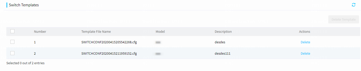
Delete switch templates
1. In the navigation pane, select Menu > Templates > Switch Templates.
2. Select the switch templates you want to delete, and then click Delete Template in the upper right corner. Alternatively, click Delete in the Actions column for the switch template you want to delete.
3. Click OK in the confirmation dialog box that opens.
Manage address pools
From this menu, you can create, edit, delete, and view IPv4 address pools, IPv6 address pools, and host name pools. After creating address pools, you can select a host name pool, IPv4 address pool, or IPv6 address pool rather than manually configure it in the OS Settings area when adding a server template. This feature significantly improves the configuration efficiency.
Manage IPv4 address pools
View IPv4 address pools
Procedure
1. In the navigation pane, select Menu > Templates > Address Pools.
2. Click the IPv4 Address Pools tab. View the IPv4 address pool list.
Figure 118 IPv4 address pools
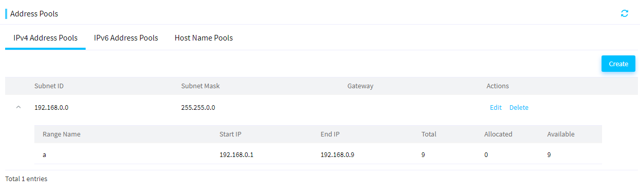
Create an IPv4 address pool
1. In the navigation pane, select Menu > Templates > Address Pools.
2. Click the IPv4 Address Pools tab. Click Add to open the Create IPv4 Address Pool page.
Figure 119 Creating an IPv4 address pool
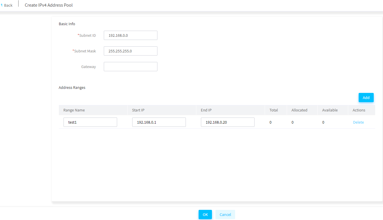
3. Enter the IPv4 subnet ID, subnet mask, and gateway (optional).
4. In the Address Ranges area, click Add. Enter the address range name, start IP, and end IP.
5. To add more address ranges, repeat the step above.
6. Click OK.
Edit an IPv4 address pool
Restrictions and guidelines
For an IPv4 address pool with address ranges, you cannot edit its subnet ID or subnet mask.
Procedure
1. In the navigation pane, select Menu > Templates > Address Pools.
2. Click the IPv4 Address Pools tab.
3. Click Edit in the Actions column for the address pool to be edited. Edit the address pool as needed.
4. Click OK.
Delete an IPv4 address range
1. In the navigation pane, select Menu > Templates > Address Pools.
2. Click the IPv4 Address Pools tab.
3. Click Edit in the Actions column for the address pool to be edited.
4. In the Address Ranges area, click Delete in the Actions column for the address range to be deleted.
Delete an IPv4 address pool
Restrictions and guidelines
Deleting an IPv4 address pool deletes all address ranges in the IPv4 address pool.
Procedure
1. In the navigation pane, select Menu > Templates > Address Pools.
2. Click the IPv4 Address Pools tab.
3. Click Delete in the Actions column for the IPv4 address pool to be deleted. In the dialog box that opens, click OK.
Manage IPv6 address pools
View IPv6 address pools
1. In the navigation pane, select Menu > Templates > Address Pools.
2. Click the IPv6 Address Pools tab. View the IPv6 address pool list.
Figure 120 IPv6 address pools
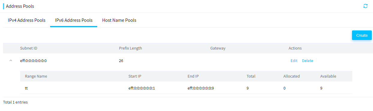
Create an IPv6 address pool
1. In the navigation pane, select Menu > Templates > Address Pools.
2. Click the IPv6 Address Pools tab. Click Add to open the Create IPv6 Address Pool page.
Figure 121 Creating an IPv6 address pool
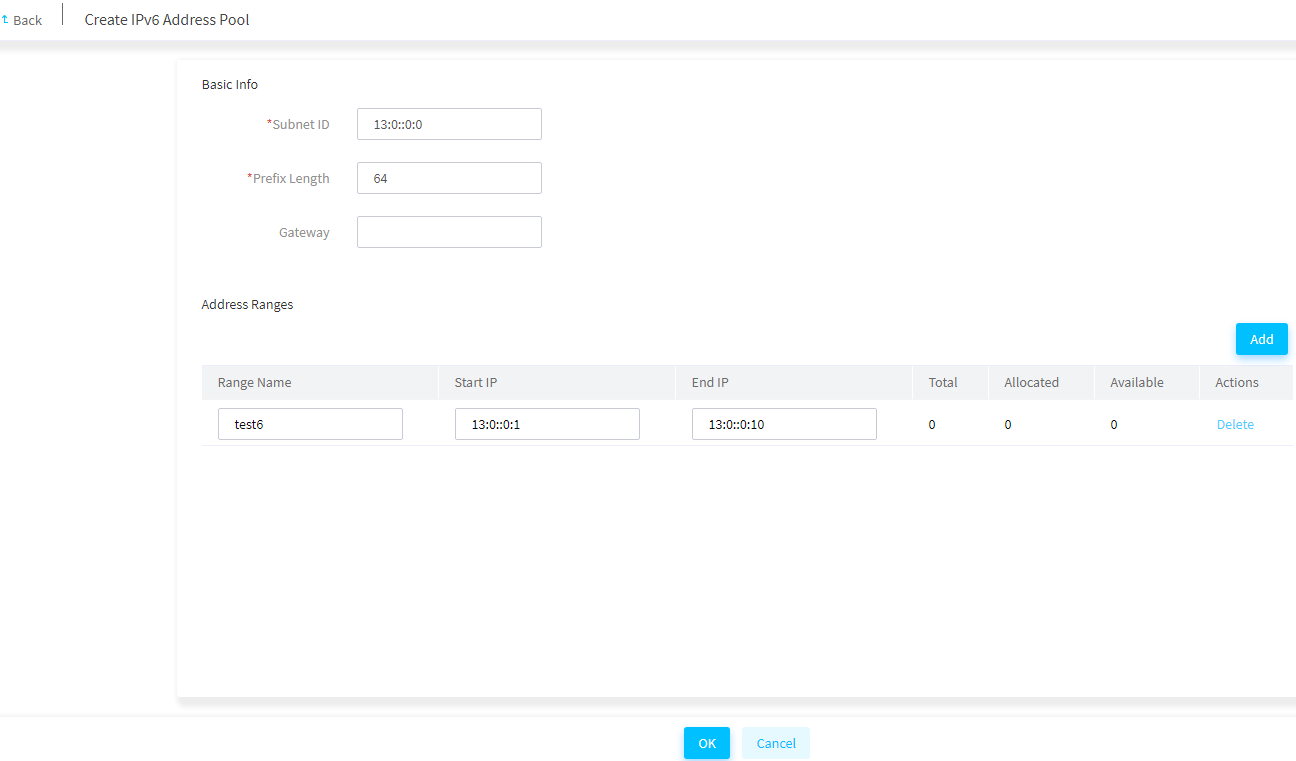
3. Enter the IPv6 subnet ID, prefix length, and gateway (optional).
4. In the Address Ranges area, click Add. Enter the address range name, start IP, and end IP.
5. To add more address ranges, repeat the step above.
6. Click OK.
Edit an IPv6 address pool
Restrictions and guidelines
For an IPv6 address pool with address ranges, you cannot edit its subnet ID or prefix length.
Procedure
1. In the navigation pane, select Menu > Templates > Address Pools.
2. Click the IPv6 Address Pools tab.
3. Click Edit in the Actions column for the address pool to be edited. Edit the address pool as needed.
4. Click OK.
Delete an IPv6 address range
1. In the navigation pane, select Menu > Templates > Address Pools.
2. Click the IPv6 Address Pools tab.
3. Click Edit in the Actions column for the address pool to be edited.
4. In the Address Ranges area, click Delete in the Actions column for the address range to be deleted.
Delete an IPv6 address pool
Restrictions and guidelines
Deleting an IPv6 address pool deletes all address ranges in the IPv6 address pool.
Procedure
1. In the navigation pane, select Menu > Templates > Address Pools.
2. Click the IPv6 Address Pools tab.
3. Click Delete in the Actions column for the IPv6 address pool to be deleted. In the dialog box that opens, click OK.
Manage host name pools
When adding a server template, you can directly select a host name pool rather than manually configure one in the OS Settings area. After the server template is applied to multiple servers to install OSs on these servers, the host names are generated for these servers in the format of prefix+index+suffix without manual configuration. This feature helps you easily identify the servers and improves the configuration efficiency.
View host name pools
Procedure
1. In the navigation pane, select Menu > Templates > Address Pools.
2. Click the Host Name Pools tab. View the host name pool list.
Figure 122 Host name pools
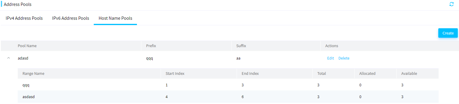
Create a host name pool
1. In the navigation pane, select Menu > Templates > Address Pools.
2. Click the Host Name Pools tab. Click Add to enter the Create Host Name Pool page.
Figure 123 Creating a host name pool
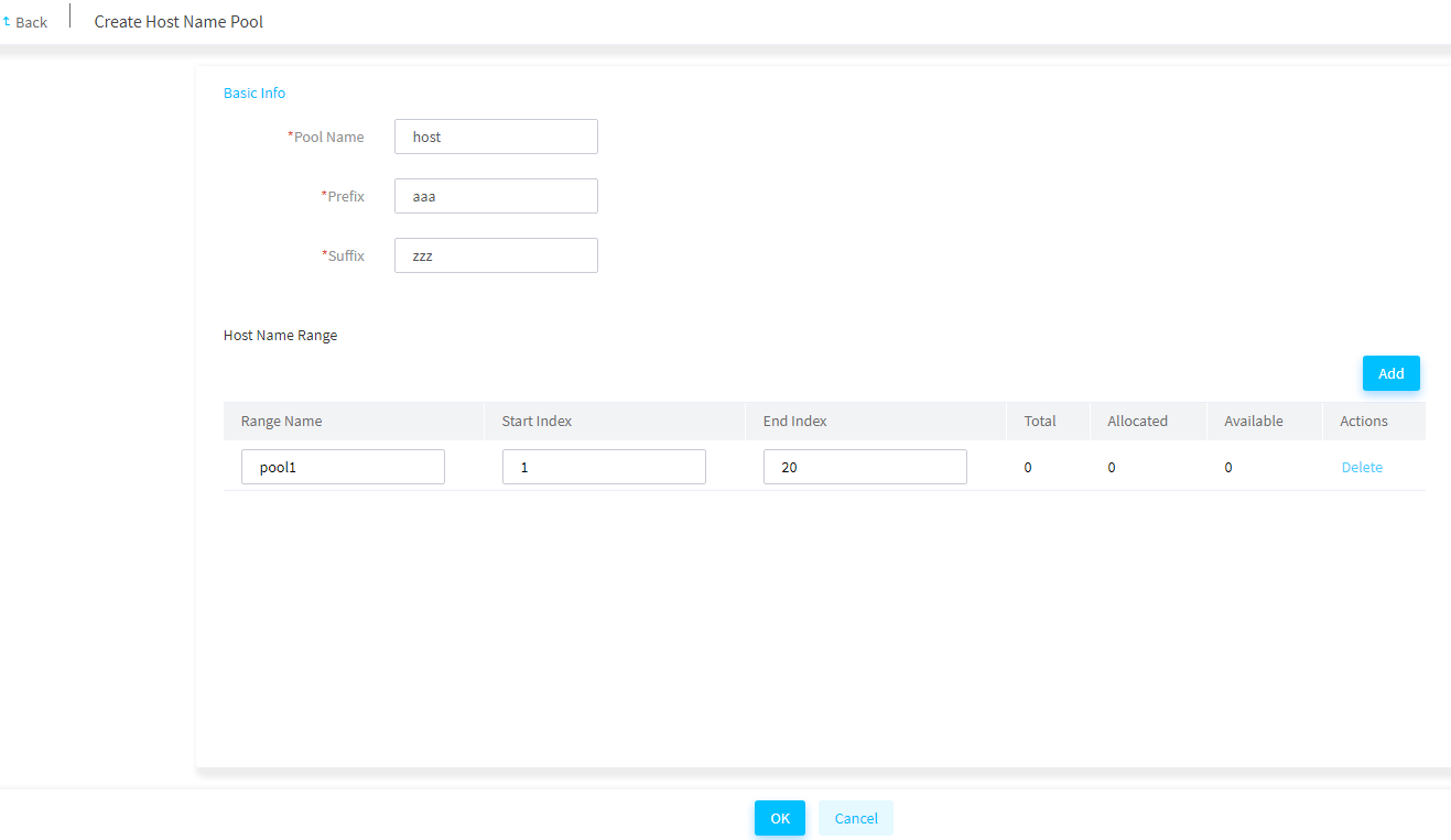
3. Enter the host name pool name, prefix, and suffix.
4. In the Host Name Ranges area, click Add. Enter the host name range name, start index, and end index.
5. To add more host name ranges, repeat the step above.
6. Click OK.
Edit a host name pool
1. In the navigation pane, select Menu > Templates > Address Pools.
2. Click the Host Name Pools tab.
3. Click Edit in the Actions column for the host name pool to be edited. Edit the host name pool as needed.
4. Click OK.
Delete a host name range
1. In the navigation pane, select Menu > Templates > Address Pools.
2. Click the Host Name Pools tab.
3. Click Edit in the Actions column for the host name pool to be edited.
4. In the Host Name Ranges area, click Delete in the Actions column for the host name range to be deleted.
Delete a host name pool
Restrictions and guidelines
Deleting a host name pool deletes all host name ranges in the host name pool.
Procedure
1. In the navigation pane, select Menu > Templates > Address Pools.
2. Click the Host Name Pools tab.
3. Click Delete in the Actions column for the host name pool to be deleted. In the dialog box that opens, click OK.
Manage network templates
From this menu, you can create, edit, delete, and view network templates or interconnect module templates in FIST. Then, you can use the networks and interconnect module templates when configuring connections in a server template. For more information about, see connecting settings in "Manage server templates."
Manage networks
From this menu, you can create, edit, delete, and view networks in FIST.
View a network
1. In the navigation pane, select Menu > Templates > Network Templates. Click the Networks tab.
2. View information about the networks on the network list. The network name format varies depending on whether a single VLAN ID or a VLAN ID range was specified during the network creation:
¡ If a VLAN ID range was specified, the network name takes the format of Network Name_VLAN ID. For example, wl1_10.
¡ If a single VLAN ID was specified, the network name takes the format of Network Name. For example, Test.
Figure 124 Networks
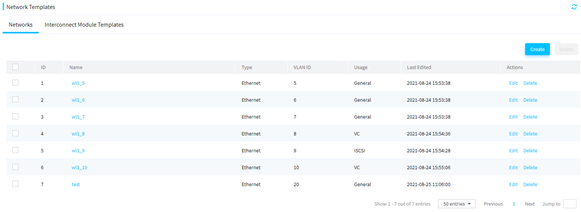
Create networks
1. In the navigation pane, select Menu > Templates > Network Templates. Click the Networks tab.
2. Click Create. The Create Network dialog box opens.
To create interconnect module templates later, you must select VC from the Usage list.
Figure 125 Creating networks
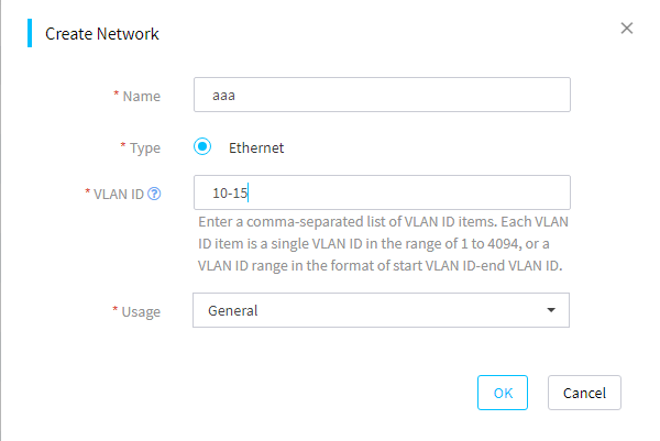
3. Configure the network parameters as follows:
¡ To create a single network, specify the network name and a VLAN ID for the network, configure other parameters as needed, and then click OK.
FIST will create only one network with the specified network name.
¡ To create multiple networks with the same network name and different VLAN IDs, specify the network name and the VLAN ID list, configure other parameters as needed, and then click OK.
FIST will create a network for each VLAN with a name in the format of Network Name_VLAN ID, for example, Blue_100.
4. Verify that the newly created networks are displayed on the Networks page.
Figure 126 Viewing the created networks
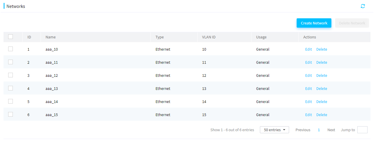
Edit a network
1. In the navigation pane, select Menu > Templates > Network Templates. Click the Networks tab.
2. Click Edit in the Actions column for the network to be edited.
3. Edit the network settings as needed.
4. Click OK.
Delete networks
1. In the navigation pane, select Menu > Templates > Network Templates. Click the Networks tab.
2. Perform either of the following steps:
¡ To bulk delete networks, select the networks and click Delete.
¡ To delete a single network, click Delete in the Actions column for the network.
3. In the dialog box that opens, click OK to confirm the operation.
Manage interconnect module templates
From this menu, you can create, edit, or delete the interconnect module templates.
View an interconnect module template
1. In the navigation pane, select Menu > Templates > Network Templates. Click the Interconnect Module Templates tab.
2. On this tab, view the interconnect module template information.
Figure 127 Interconnect module template information page
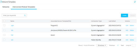
Create an interconnect module template
1. In the navigation pane, select Menu > Templates > Network Templates.
2. Click the Interconnect Module Templates tab.
3. Click Create.
4. In the dialog box that opens, configure the interconnect module template.
The Network list displays only networks with the usage as VC.
Figure 128 Creating an interconnect module template
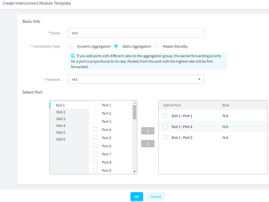
5. Click OK.
Figure 129 Interconnect module template list
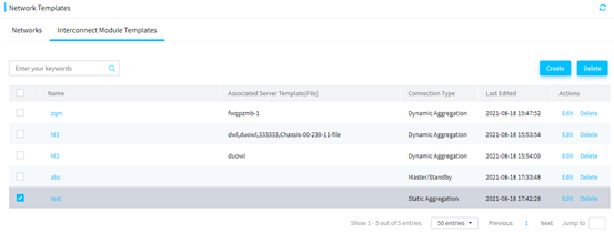
Edit an interconnect module template
1. In the navigation pane, select Menu > Templates > Network Templates.
2. Click the Interconnect Module Templates tab.
3. Click Edit in the Actions column for the interconnect module to be edited.
4. Click OK.
Delete an interconnect module template
1. In the navigation pane, select Menu > Templates > Network Templates.
2. Click the Interconnect Module Templates tab.
3. Perform either of the following steps:
¡ To bulk delete interconnect modules, select the interconnect modules and click Delete.
¡ To delete a single interconnect module, click Delete in the Actions column for the interconnect module.
4. In the dialog box that opens, click OK to confirm the operation.
Manage images
Restrictions and guidelines
· When the free space is about 10G, you cannot upload images. In this case, as a best practice, delete the images that are not needed.
· When FIST runs in Windows, for an uploaded image file to be used properly, you must run FIST as an administrator.
· The name of an image file to upload can contain up to 64 characters, including the file extension.
· For the upload to succeed, make sure the name of the image to upload is different from the name of any image on the image list.
· For the upload to succeed, do no refresh the page during the upload process.
· To avoid exceptions during operating system installation, make sure the image file to upload is downloaded from its official website and has not been edited.
Procedure
1. In the navigation pane, select Menu > Templates > Images to enter the page as shown in Figure 130.
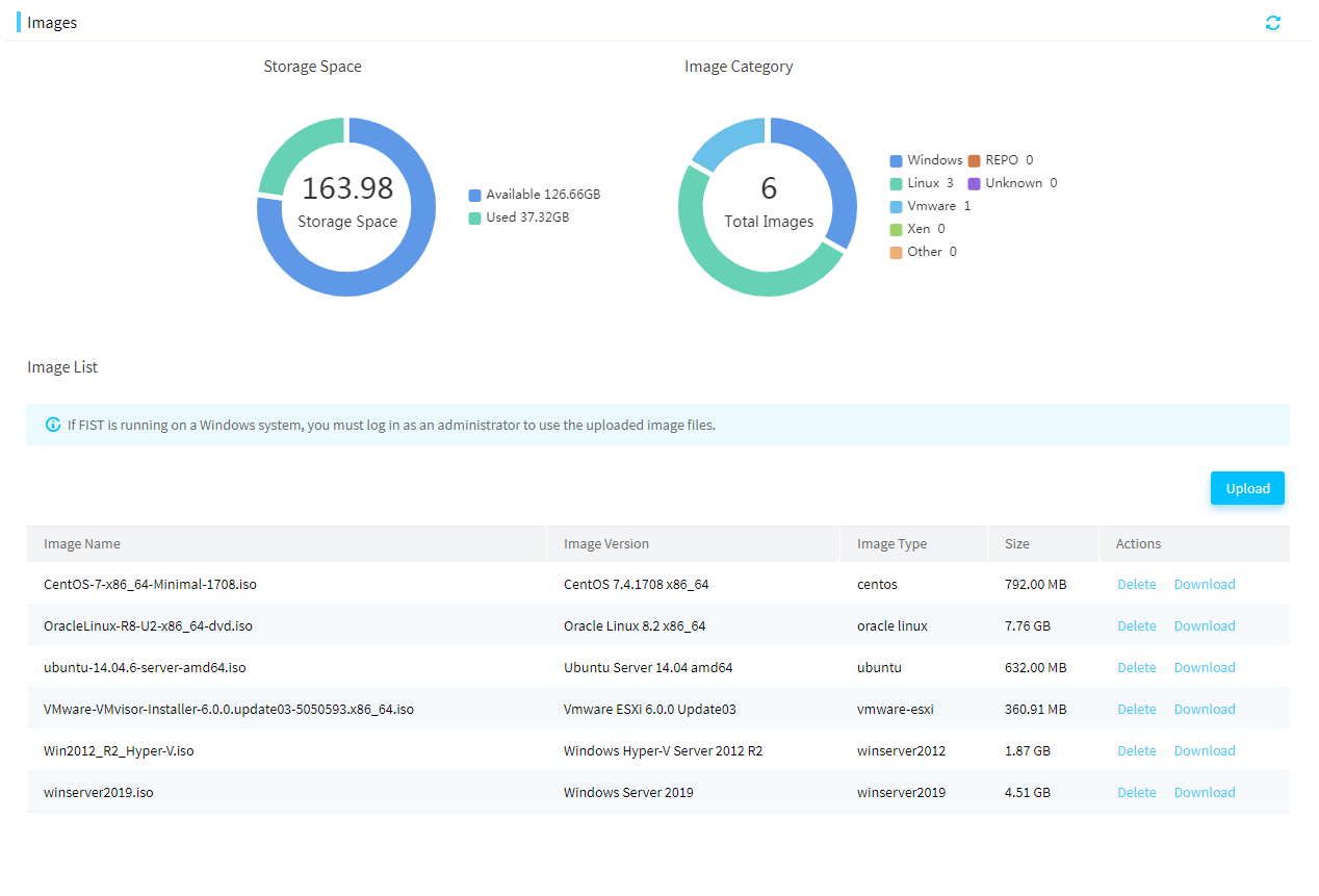
2. Click Upload in the upper right corner of the image list. The Upload Image dialog box opens, as shown in Figure 131.
Figure 131 Uploading an OS image
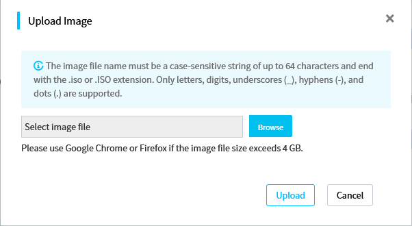
3. Click the Browse button. In the dialog box that opens, select the image file to upload.
4. Click Upload to upload the OS image file to the FIST server.
After the upload is completed, the OS image file is displayed on the image management page.
5. (Optional.) If the uploaded image file is a repository file, you can synchronize the file to the Menu > Templates > Repository page by clicking Sync to Repo in the Actions column for the file.
Clone images
About this task
|
|
IMPORTANT: · This feature is available only when FIST runs in the AE module or the VM. · To use this feature, you must install iFIST on the managed servers, and make sure iFIST has a system IP address that can communicate with FIST. · This feature is supported in FIST 2.00.13 and later. · This feature supports VMware operating systems in FIST 2.00.15 and later. |
This feature allows you to perform the following tasks:
· Export images for OS cloning: Perform this task to export the OS file on the specified logical drive of a server and save the file as an image file. This function supports exporting the following OSs:
¡ OSs manually installed through images mounted to KVM or USB flash drive.
¡ OSs installed through iFIST.
¡ OSs installed through server templates.
¡ OSs installed through PXE.
· Manage images: Manage image files. Perform this task to display image-related information, delete image files, and delete the tags for applying images to blade servers.
The exported image files for OS cloning can be added to the OS settings in a server template and applied. For more information, see "Manage server templates" and "Apply server templates."
Table 10 describes the support of OS cloning for operating systems.
Table 17 Support of OS cloning for operating systems
|
Operating systems |
Servers |
|
· Red Hat Enterprise Linux 7.2(64 bit) · Red Hat Enterprise Linux 7.3(64 bit) · Red Hat Enterprise Linux 7.4(64 bit) · Red Hat Enterprise Linux 7.5(64 bit) · Red Hat Enterprise Linux 7.6(64 bit) · Red Hat Enterprise Linux 7.7(64 bit) · Red Hat Enterprise Linux 7.8(64 bit) · Red Hat Enterprise Linux 7.9(64 bit) · Red Hat Enterprise Linux 8.0(64 bit) · Red Hat Enterprise Linux 8.1(64 bit) · Red Hat Enterprise Linux 8.2(64 bit) · Red Hat Enterprise Linux 8.3(64 bit) · Red Hat Enterprise Linux 8.4(64 bit) · CentOS 7.4 (64 bit) · CentOS 7.5 (64 bit) · CentOS 7.6 (64 bit) · VMware ESXi 6.5 U1 (64 bit) · VMware ESXi 6.5 U2 (64 bit) · VMware ESXi 6.5 U3 (64 bit) · VMware ESXi 6.7 (64 bit) |
· H3C UniServer B5700 G3 · H3C UniServer B5800 G3 · H3C UniServer B7800 G3 · H3C UniServer E3200 G3 · H3C UniServer R2700 G3 · H3C UniServer R2900 G3 · H3C UniServer R4700 G3 · H3C UniServer R4900 G3 · H3C UniServer R4950 G3 · H3C UniServer R5300 G3 · H3C UniServer R6700 G3 · H3C UniServer R6900 G3 · H3C UniServer R8900 G3 · H3C UniServer R4500 G3 · H3C UniServer R4900 G5 · H3C UniServer R4700 G5 · H3C UniServer R6900 G5 · H3C UniServer R4300 G5 · H3C UniServer R4950 G5 · H3C UniServer R4930 G5 · H3C UniServer R4330 G5 · H3C UniServer R5500 G5 · H3C UniServer B5700 G5 · H3C UniServer R5300 G5 |
Prerequisites
To use this feature, you must add HDM server nodes to FIST first. For more information, see "Add, edit, or delete servers."
Restrictions and guidelines
· This function cannot export partition-encrypted OSs
· FIST supports only LSI storage controllers operating in RAID mode (some LSI storage controllers do not require operating mode configuration).
· Before exporting images for OS cloning, make sure the HDM of the server operates properly and is turned on.
· Before exporting the OS image from a logical or physical drive on a server, make sure the drive is in valid state and has only one operating system installed.
· When the free space is 10G or lower, you cannot export images for cloning. In this case, as a best practice, delete the images that are not needed. For more information about the free space, access the Menu > Templates > Images page. During the clone&export process, do not power off or reboot the server. The clone&export process takes several minutes. Please wait patiently.
· When exporting images for OS cloning, follow these restrictions and guidelines according to the OS type:
¡ Linux
- When the server operates in UEFI mode, you can export only the operating systems installed in UEFI mode. When the server operates in legacy mode, you can export only the operating systems installed in legacy mode.
- The data in the system partitions (including /, /usr, /usr/local, /var, and /home) can be exported. If files in the /run, /proc, /media, and /sys directories are not exported, data in the other partitions (including swap and data partitions) cannot be exported.
- After you apply a cloned OS image file to a server, the partition information on the server is the same as the OS before export. Supported file systems include ext2, ext3, ext4, VFAT, XFS, and LVM. The btrfs file system is not supported. LVM thin provisioning supports only the liner mode.
¡ VMware ESXi
- Before exporting images for OS cloning, make sure the OS had been normally shut down once rather than shut down by forcibly powering off, so that the OS can save the configuration file related to the system status. Otherwise, the network settings in the image when you clone and export the image do not take effect.
- Data files of the VMware ESXi operating system cannot be exported. As a best practice, separate the system partitions from the data partitions.
- After applying a cloned image file, to create data partitions in the system logical drive, you must create them manually. A cloned OS image does not support retaining data partitions in the VMware ESXi operating system.
Procedure
1. In the navigation pane, select Menu > Templates > Clone Images.
To quickly filter out the target image, you can use the label or enter a keyword in the search area.
Figure 132 Clone Images
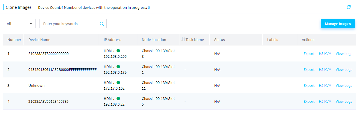
2. Click Export in the Actions column for a device, as shown in Figure 133. In the dialog box that opens, specify a name for the clone&export task, specify a name for the OS image file to be exported, select a storage controller and target drive, and click OK to issue the cloning instruction.
Figure 133 Exporting images for OS cloning
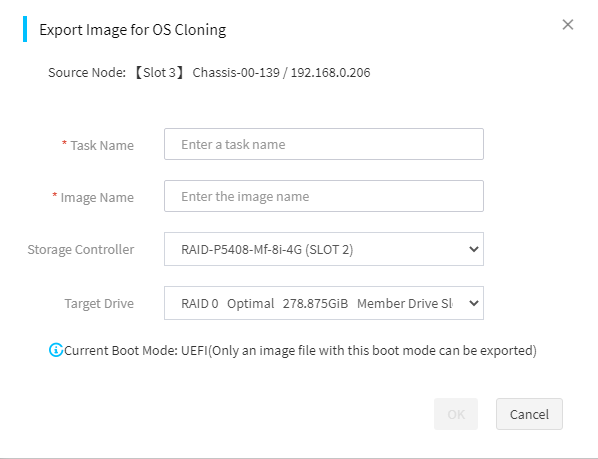
3. To see the cloning progress, see the Status column.
4. Click Manage Images to enter the image management page as shown in Figure 134. On this page, you can view the type and size of each exported image file.
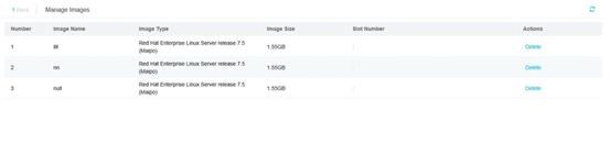
5. (Optional.) To delete an image, click Delete for the image to delete. In the dialog box that opens, click OK.
6. To view detailed logs, click View Logs for the device.
Configure diskless boot
Introduction
|
|
IMPORTANT: · This feature is available only when FIST runs in the AE module. · This feature is supported in FIST 2.00.13 and later. |
This feature complies with the iSCSI protocol and provides a remote storage volume for blade servers. You can manually install operating systems in the storage volume to implement diskless boot. For how to connect to a remote storage volume and install operating systems in the volume, see “Appendix.”
When using diskless boot, as a best practice, use the local drives only as data drives, and make sure the local drives have no OS installed and have no system boot programs. Otherwise, the diskless boot process might be affected after an OS is installed.
Storage volumes for diskless boot can be connected only when BIOS operates in UEFI mode.
Common file systems (for example, ext4 and xfs) cannot be mounted to multiple nodes at the same time. Therefore, except when you use a special cluster file system, do not try to use two NICs to connect to the same iSCSI volume. Otherwise, the file system might be damaged and the OS might fail to start.
Supported operating systems
|
|
IMPORTANT: This feature supports VMware operating systems in FIST 2.00.15 and later. |
The following operating systems support diskless boot:
· Red Hat Enterprise Linux 7.5 (64 bit)
· Red Hat Enterprise Linux 8.2 (64 bit)
· CentOS 7.5 (64 bit)
· CentOS 8.2 (64 bit)
· VMware ESXi 6.5 U2 (64 bit)
· VMware ESXi 6.7 (64 bit)
· VMware ESXi 7.0 U2 (64 bit)
Create a volume
About this task
Perform this task to create an empty iSCSI volume for the iSCSI client to connect. You can manually install operating systems in the storage volume to implement diskless boot.
Procedure
1. In the navigation pane, select Menu > Templates > Diskless Boot to enter the page as shown in Figure 135. On this page, you can view existing iSCSI volumes.
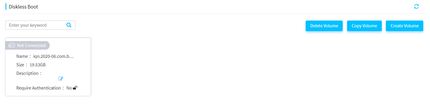
2. Click Create Volume. In the dialog box that opens, enter the name, capacity, and description for the volume.
|
|
NOTE: The iSCSI volume name must comply with the iSCSI Qualified Name (IQN) format as follows: iqn.yyyy-mm.<reversed domain name>[:identifier], for example, iqn.2014-10.dev.iscsi-target:disk. |
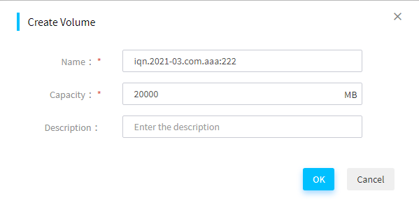
Copy a volume
About this task
Copy an existing iSCSI volume without any modification. After copying an iSCSI volume with a supported operating system installed, you can directly use the operating system.
The storage volume is completely copied, and the pure software packages installed in the storage volume are inherited. However, the hardware-related settings might vary with the system and hardware environments. Take the NIC settings as an example. If the source node and the target node both have the NIC with the same name, the NIC settings on the source node will take effect on the target node. If the source node uses a static IP, the target node must use the same static IP, which must be manually edited on the target node. If a storage volume is copied to a large number of target nodes, as a best practice, enable DHCP for IP address allocation.
After copying a volume with a VMware ESXi operating system installed, follow these restrictions and guidelines:
· As a best practice, separate the system partitions from the data partitions. Do not store the service data (for example, VM data) in the diskless boot volume. Otherwise, errors might occur after the volume is copied.
· A volume with a VMware ESXi operating system installed cannot be used across multiple blade servers.
· You can store data in a manually added iSCSI remote storage volume except the iSCSI boot volume in a VMware ESXi operating system. If you do this before copying the iSCSI volume, the added data storage configuration information will be lost after you copy the iSCSI volume. To re-connect to the remote volume, you must manually restore the connection.
· A copied VMware ESXi operating system might automatically reboot after the first boot. This is normal. The system can operate properly after the second reboot.
Procedure
|
|
IMPORTANT: To ensure complete data consistency on the source node and target node, as a best practice, copy the storage volume when the source node is not running any services or is shut down. |
To copy a volume:
1. In the navigation pane, select Menu > Templates > Diskless Boot to enter the page as shown in Figure 135.
Click Copy Volume, and click ![]() in
the upper right corner of the volume to copy.
in
the upper right corner of the volume to copy.
2. In the dialog box that opens as shown in Figure 137, enter the volume name. The size of the volume generated through copying is the same as that of the copied volume, and cannot be edited.
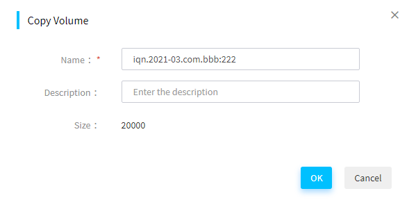
3. Click OK to start copying. Copying an iSCSI volume takes a period of time. Do not switch to any other pages during the copying process.
Delete a volume
About this task
Perform this task to delete an existing iSCSI volume.
Procedure
1. In the navigation pane, select Menu > Templates > Diskless Boot to enter the page as shown in Figure 135.
2. Click Delete Volume.
Click the ![]() icon in the upper right corner of the storage volume to delete.
icon in the upper right corner of the storage volume to delete.
3. In the dialog box that opens, click OK to delete the storage volume.
Set authentication
About this task
Set the iSCSI CHAP authentication information, which is used for authenticating an iSCSI client connecting to the iSCSI storage volume.
Procedure
1. In the navigation pane, select Menu > Templates > Diskless Boot to enter the page as shown in Figure 135.
2. Click ![]() or
or ![]() following
the Require Authentication field for an iSCSI
volume.
following
the Require Authentication field for an iSCSI
volume. ![]() indicates authentication is set.
indicates authentication is set. ![]() indicates
authentication is not set.
indicates
authentication is not set.
3. In the dialog box that opens, select Enable Authentication and enter the username and password for the storage volume. The iSCSI CHAP authentication password is a string of 12 to 16 characters.
4. Click OK.
Figure 138 Authentication settings
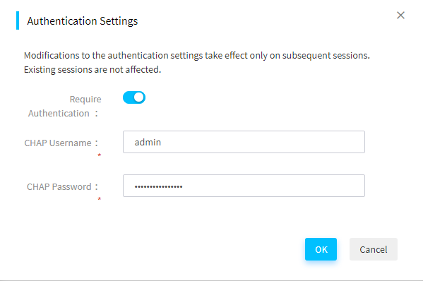
Deploy servers
Apply enclosure templates
Perform this task to apply an enclosure template to enclosures.
After an enclosure template is applied to an enclosure, FIST binds the server templates to the blade server slots according to the settings in the enclosure template. Whenever a server is installed in a slot of the enclosure, FIST automatically configures the server by using the bound server template when FIST runs in AE modules.
After applying an enclosure template to an enclosure, FIST automatically creates an enclosure configuration file for the enclosure based on the applied template.
For each blade server slot that is bound to a server template through application of an enclosure template, FIST creates an enclosure slot configuration file.
If the server to which the server template will be applied is not managed by FIST, FIST adds the server to the managed service list before applying the bound template to it.
Apply an enclosure template to enclosures
Restrictions and guidelines
In an enclosure template, you can bind two server templates to the two half-width slots in a full-width slot area. If a full-width blade server is installed in the full-width slot, FIST applies the server template bound to the half-width slot on the left side to the server.
For the connection settings function in an enclosure template to take effect, you must preconfigure VC before applying the enclosure template.
If a slot of an enclosure is bound to a server configuration template that contains the VC configuration, the VC configuration will take effect only when the enclosure configuration template or file is applied. If you apply the server configuration template directly, the VC configuration does not take effect.
Do not perform the following tasks when applying a configuration template:
· Power off or restart the device.
· Use KVM to perform mounting operations.
If the configuration contains other settings besides HDM settings, make sure the enclosure to which the template is applied is shut down.
If the HDM settings contain power capping settings, applying the template might cause the enclosure to be shut down.
Procedure
1. In the navigation pane, select Menu > Deployment > Enclosures > Apply Enclosure Templates.
Figure 139 Apply Enclosure Templates page
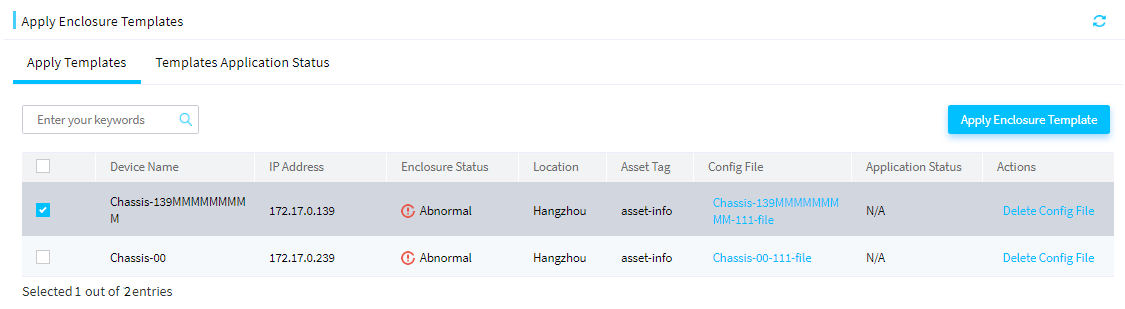
2. Select the target enclosures, and click Apply Enclosure Template. The Apply Enclosure Template dialog box opens.
Figure 140 Apply Enclosure Template dialog box
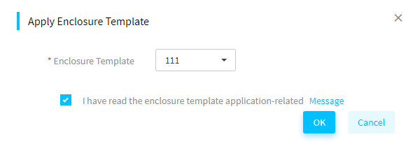
3. Select an enclosure template you want to apply to the selected enclosures and select I have read the enclosure template application-related Message.
4. Click OK.
The Template Application Status tab opens, displaying the template application status and progress.
5. To view template application information about a server, click Logs in the Actions column for the server.
Apply an enclosure configuration file
About this task
After an enclosure template is applied to an enclosure, the system automatically generates a configuration file for the enclosure and names the file in the format of Enclosure Name-Template Name-file. The configuration file contains all the settings in the enclosure template. You can edit the settings in the configuration file, and then apply the configuration file to the enclosure.
Procedure
1. In the navigation pane, select Menu > Deployment > Enclosures > Apply Enclosure Templates.
2. Click the configuration file name link for an enclosure. The configuration file details page opens.
Figure 141 Enclosure configuration file details page
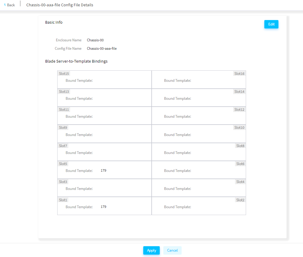
3. (Optional.) Review the configuration file settings. To edit the settings, click Edit in the upper right corner.
4. Click Apply to apply the configuration file.
Delete an enclosure configuration file
1. In the navigation pane, select Menu > Deployment > Enclosures > Apply Enclosure Templates.
2. Click Delete Config File in the Actions column for the target enclosure.
3. In the dialog box that opens, click OK.
Enclosure configuration files
About this task
After applying an enclosure template to an enclosure, FIST automatically generates an enclosure configuration file for the enclosure based on the applied template.
In an enclosure template, you can bind two server templates to the two half-width slots in a full-width slot area. If a full-width blade server is installed in the full-width slot, FIST applies the server template bound to the half-width slot on the left side to the server.
The enclosure configuration file contains all the settings in the enclosure template. You can edit the settings in the enclosure configuration file, and then apply the edited file to the enclosure as needed.
Procedure
1. In the navigation pane, select Menu > Deployment > Enclosures > Enclosure Config Files.
Figure 142 Enclosure configuration files
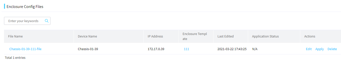
2. Click a file name to view detailed information about the selected enclosure configuration file.
3. (Optional.) To edit an enclosure configuration file, click Edit in the Actions column for the target file. In the dialog box that opens, edit the settings and then click Save.
Figure 143 Editing an enclosure configuration file
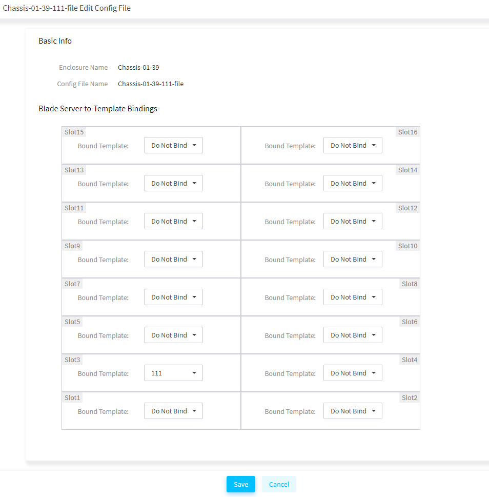
4. Click Apply in the Actions column for the enclosure configuration file you want to apply. In the dialog box that opens, click OK.
5. (Optional.) To delete an enclosure configuration file, click Delete in the Actions column for the target file. In the dialog box that opens, click OK.
Enclosure slot configuration files
About this task
FIST automatically creates an enclosure slot configuration file for each blade server slot that is bound to a server template through application of an enclosure template.
You can edit the settings in the enclosure slot configuration file, and then apply the edited file to the blade server as needed.
If an enclosure slot configuration file (or enclosure configuration file) is automatically applied after a node is unplugged and plugged, the VC configuration uses the policy file on the OM.
Procedure
1. In the navigation pane, select Menu > Deployment > Enclosures > Enclosure Slot Config Files.
Figure 144 Enclosure slot configuration files
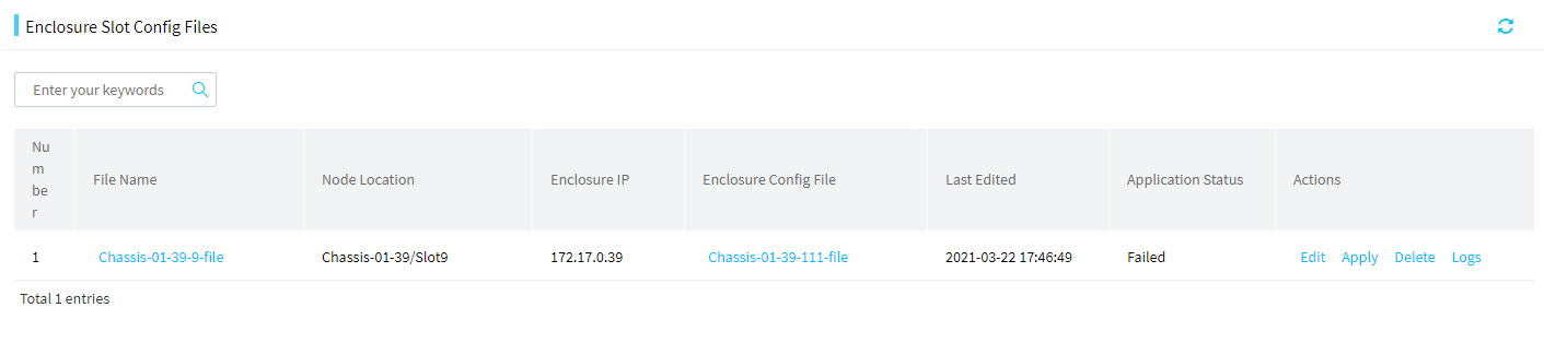
2. Click a file name to view detailed information about the selected enclosure slot configuration file.
3. (Optional.) To edit an enclosure slot configuration file, click Edit in the Actions column for the target file. In the dialog box that opens, edit the settings and then click Save.
Figure 145 Editing an enclosure slot configuration file
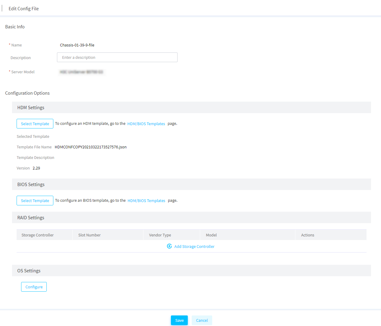
4. Click Apply in the Actions column for the enclosure slot configuration file you want to apply. In the dialog box that opens, click OK.
5. Click Logs in the Actions column for the enclosure slot configuration file to view its application logs.
6. (Optional.) To delete an enclosure slot configuration file, click Delete in the Actions column for the target file. In the dialog box that opens, click OK.
Apply server templates
Prerequisites
To use this feature, you must add HDM server nodes to FIST first. For more information, see "Add, edit, or delete servers."
Restrictions and guideline
Apply a server template to servers
Perform this task to apply a server template to servers. By applying a server template to a server, FIST deploys the HDM, BIOS, connection, RAID, and OS installation settings in the template to the server.
|
|
IMPORTANT: · To install an OS on a server by using a template with a cloned image or through FIST 2.00.26 or earlier, a server must be able to communicate with FIST through the system IP address of iFIST. iFIST obtains its system IP address from the DHCP server, which must reside on the same LAN as the server. · As of FIST 2.00. 26, this feature can work with HDM (HDM 2.11 or later) and iFIST (iFIST 1.01.26 or later) to implement out-of-band OS installation. · On a server running HDM of a version earlier than HDM 2.11 and iFIST of a version earlier than 1.01.26, FIST 2.00.26 can install an OS by communicating with iFIST on the server. |
Restrictions and guidelines
· If the configuration contains other settings besides HDM settings, make sure the server to which the template is applied is shut down.
· If the HDM settings contain power capping settings, applying the template might cause the server to be shut down.
· Before applying a template to servers, make sure no operations are in progress on the servers. During the template application process, do not perform other operations contained in the settings.
· During the template application process on a server, do not perform the following operations:
¡ Power off or reboot the server.
¡ Update, reset, or restore the factory defaults for HDM on the server.
¡ Perform mount operations through KVM.
· The privilege to apply HDM settings depends on the network privilege of the HDM account. Make sure the user has the privilege to this operation.
· After the HDM settings are successfully applied to a target server, the server will automatically reboot. The HDM status will restore in several minutes.
· To successfully apply the HDM or BIOS settings to a server, make sure the HDM or BIOS version in the template is the same as the HDM or BIOS version of the server.
· When you apply HDM settings of version HDM-1.11.19 or earlier (including all HDM-1.10.XX versions), the configuration import policy of FIST is the same as that of HDM. If the HDM settings are copied to multiple servers, the server HDM IPs might conflict. Use this feature with caution.
· When you apply HDM settings of version HDM-1.11.20 or later, FIST does not edit the HDM IP settings. To avoid IP conflicts, do not configure the same IP address for multiple HDMs.
· When you apply an HDM template to servers, the IP settings, VLAN settings, and LLDP settings in the HDM template will not take effect in FIST of version FIST-2.31 or later.
· FIST supports only LSI storage controllers operating in RAID mode (some LSI storage controllers do not require operating mode configuration).
· As a best practice, do not install an OS through applying a template on a disk of 2TB or larger. Such an installation might fail.
Procedure
1. In the navigation pane, select Menu > Deployment > Servers > Apply Server Templates to enter the page as shown in Figure 146.
Figure 146 Applying server templates
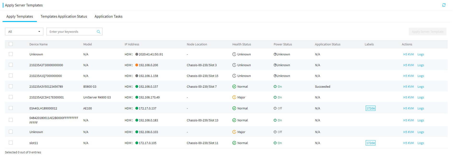
2. Select the target servers, and click Apply Server Template. On the page that opens, perform the following tasks.
To quickly filter out the target server, you can use the label or enter a keyword in the search area.
3. In the dialog box that opens as shown in Figure 147, select the server template to apply and verify the device name and device status.
Figure 147 Applying a server template
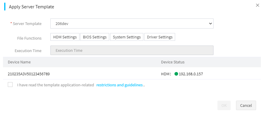
4. Set scheduled deployment. If you enable scheduled deployment, you can select the scheduled time from the Execution Time field. FIST will start deployment at the scheduled time. If you disable scheduled deployment, FIST immediately starts deployment after you click OK.
5. Select I have read the template application-related restrictions and guidelines.
6. Click OK to start applying the template to the selected servers.
The Template Application Status tab opens, displaying the template application status and progress.
7. To view detailed template application information about a server, click Logs in the Actions column for the server.
8. If you enable scheduled deployment, the application task page opens after the template is applied. On this page, you can see the task execution state.
¡ To stop an application task, click Stop in the Actions column for that task.
¡ To delete an application task, click Delete in the Actions column for that task.
Apply a server configuration file
After an enclosure template (file) is applied to the servers in an enclosure, the system automatically generates a configuration file named in the format of Enclosure Name-Slot-file for each server. You can edit the configuration file for a server as needed, and then apply the configuration file to the server.
Procedure
1. In the navigation pane, select Menu > Deployment > Servers > Apply Server Templates.
2. Click the configuration file name link for a server. The configuration file details page opens.
Figure 148 Server configuration file details page
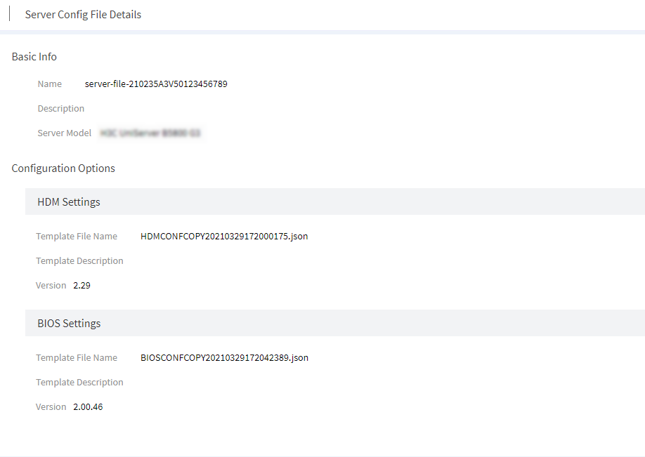
3. (Optional.) Review the configuration file settings. To edit the settings, click Edit in the upper right corner.
4. Click Apply to apply the configuration file.
Delete a server configuration file
1. In the navigation pane, select Menu > Deployment > Servers > Apply Server Templates.
2. Click Delete Configuration File in the Actions column for the target server.
3. In the dialog box that opens, click OK.
Server configuration files
A server configuration file is a configuration file generated for a single server after a server template is successfully applied. For how to apply a server template, see "Apply server templates."
You can edit the server configuration file of a server and then apply it to the same server again. This feature allows you to fast edit the configuration of a server without editing a server template.
View a server configuration file
In the navigation pane, select Menu > Deployment > Server Config Files to view the server configuration files in FIST.
Figure 149 Server configuration files
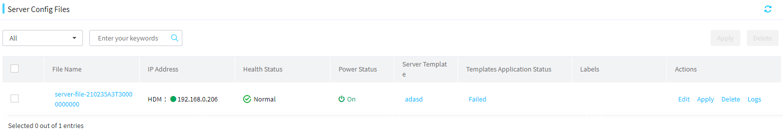
Edit a server configuration file
Restrictions and guidelines
When the IP address, subnet mask, or gateway is modified in the OS settings of a server configuration file, the IP address that the server template assigned to the server is withdrawn. The withdrawn IP address can be assigned to another server by the server template.
Procedure
1. In the navigation pane, select Menu > Deployment > Server Config Files.
2. Click Edit in the Actions column for the server configuration file to be edited. On the page shown in Figure 150, edit the server configuration file as needed.
Figure 150 Editing a server configuration file
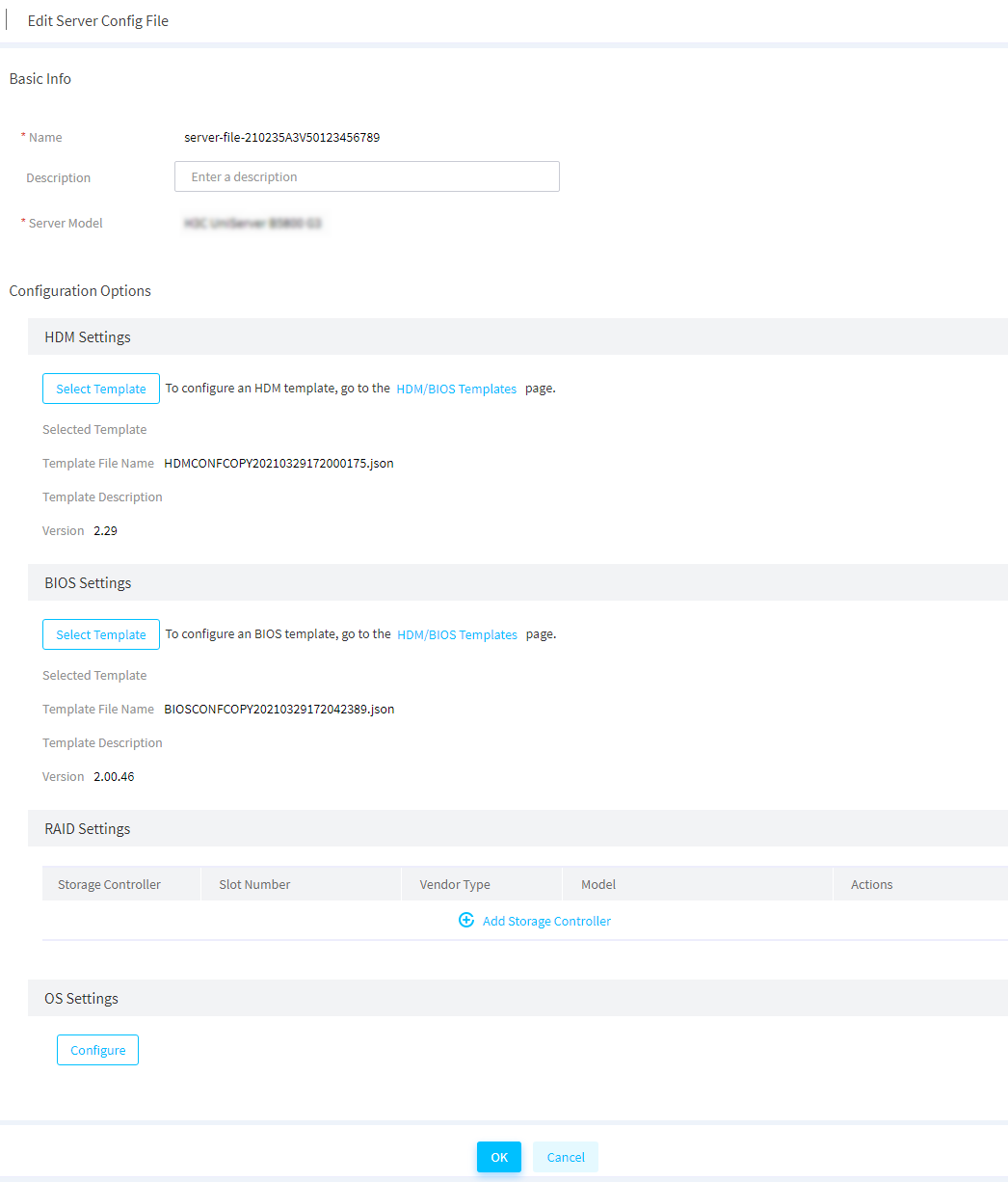
3. Review the configuration file change, and click OK.
Delete server configuration files
Restrictions and guidelines
When a server configuration file of a server is deleted, the IP address that the server template assigned to the server is withdrawn. The withdrawn IP address can be assigned to another server by the server template.
Procedure
1. In the navigation pane, select Menu > Deployment > Server Config Files.
2. Perform either of the following steps:
¡ To delete a single server configuration file, click Delete in the Actions column for the server configuration file to be deleted.
¡ To bulk delete server configuration files, select the server configuration files to be deleted, and click Delete in the upper right corner.
3. In the dialog box that opens, click OK to confirm the operation.
Apply server configuration files
Restrictions and guidelines
If the application status of a server configuration file is Failed, see the application logs to obtain more information about the server configuration file.
Procedure
1. In the navigation pane, select Menu > Deployment > Server Config Files to enter the page shown in Figure 151.
Figure 151 Server Config Files page
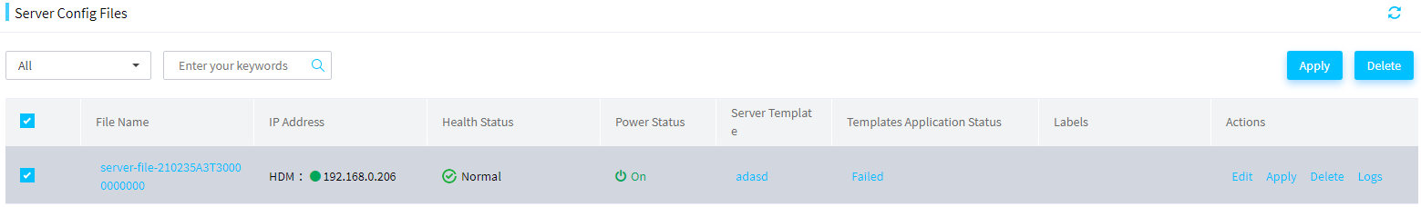
2. Perform either of the following steps:
¡ To apply a single server configuration file, click Apply in the Actions column for the server configuration file to be applied.
¡ To bulk apply server configuration files, select the server configuration files to be applied, and click Apply in the upper right corner.
3. In the dialog box that opens, click OK to confirm the operation.
Update components
From this menu, you can update the components of the local nodes and remote nodes. The components include HDM, BIOS, CPLD, and firmware and drivers for some hardware.
A local node refers to the FIST server. The local task contains only local nodes. The Update Components page will automatically add a local task named localhost. The local task cannot be deleted.
The remote nodes refer to the managed servers. The remote nodes include HDM and FIST SMS.
|
|
TIP: When the HDM version is between HDM-1.11.08 and HDM-1.30.18 for a server, if you use a REPO to upgrade the BIOS firmware through FIST SMS on FIST, the BIOS settings cannot be retained. |
Add a task
About this task
Perform this task to add multiple managed servers to a task, so that you can bulk update the server nodes.
Procedure
1. In the navigation pane, select Menu > Deployment > Update Components.
Node localhost is the host where the FIST server software is installed. When FIST is being installed on a server, the task named localhost is automatically created. The task named localhost cannot be deleted. Another local task named localhost cannot be added.
Figure 152 Updating components
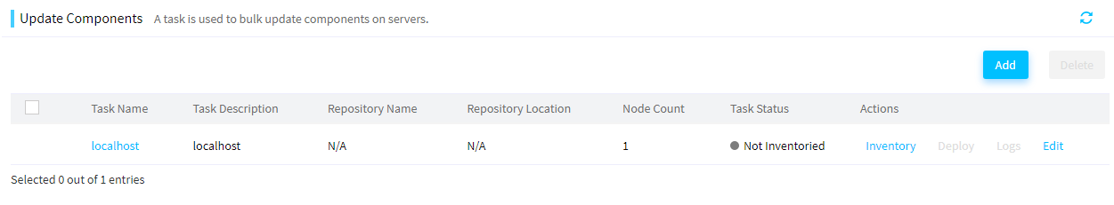
2. Click Add to enter the page as shown in Figure 153. On this page, perform the following steps:
a. Enter the task name and description.
b. Select the target server nodes.
c. Select the repository to be assigned to the servers from the Repository list.
d. In the Installation Options area, configure the HDM/BIOS firmware configuration retention policies and the server restart policy.
e. Click OK.
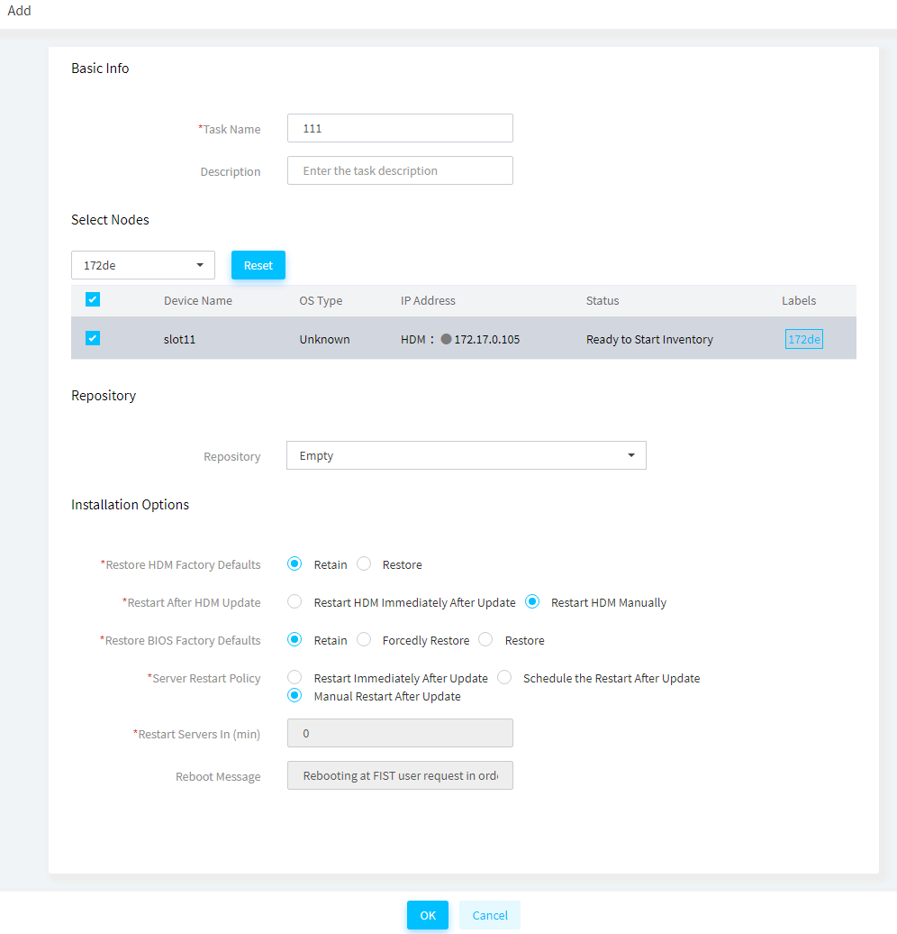
Inventory and deploy a task
About this task
Perform the following tasks to update components for nodes in a task:
· Inventory a task: Obtain information about each node in the task, and then filter out components applicable to the nodes from the repository. Before inventorying a task, make sure all repositories bound to the task have been inventoried.
· Deploy a task: Install the components to update on the nodes in the task.
Procedure
1. In the navigation pane, select Menu > Deployment > Update Components.
2. Click Inventory in the Actions column for the target task. In the dialog box that opens, select the target repository from the Repository list.
Figure 154 Inventorying a task
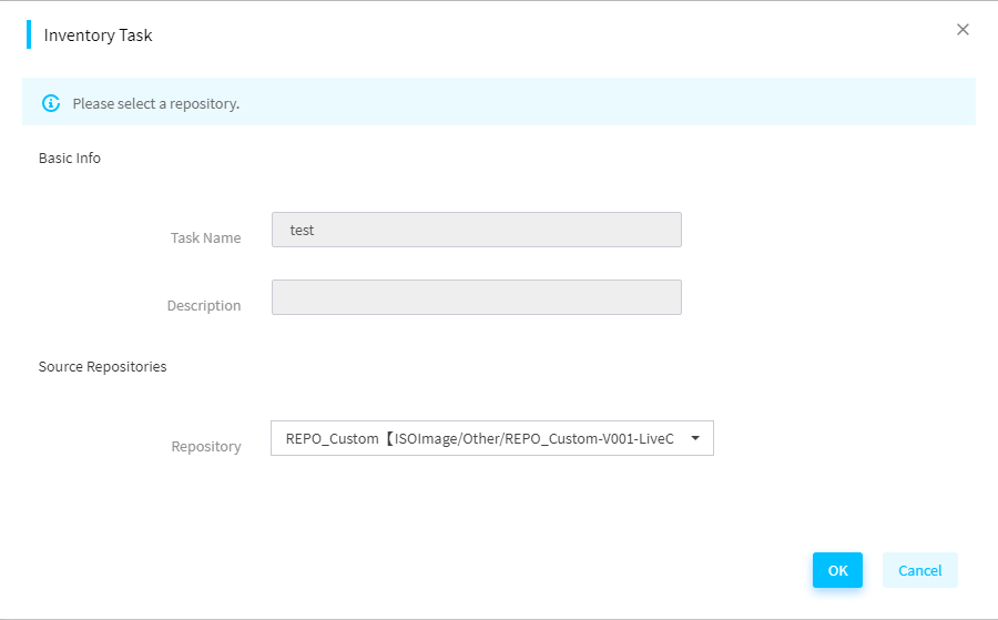
3. As shown in Figure 155, after inventorying is completed, the Deploy link appears. The local task named localhost cannot be deployed together with other tasks.
|
|
IMPORTANT: · Failure to inventory or deploy components on some nodes in the task does not affect the whole inventorying and deployment process. · When a task is being inventoried or deployed, FIST will automatically skip nodes in abnormal state in the task. If all nodes in a task are in abnormal state, you cannot inventory or deploy the task. |
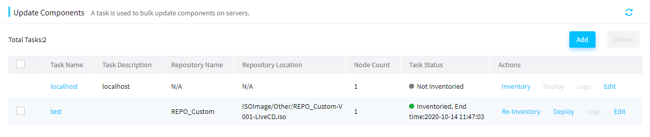
4. Click Deploy. The page as shown in Figure 156 opens. Check the component version to determine whether to update the component. Click the name of a component to view the component details. According to the dependent items of the component, determine whether you need to update the dependent components of the current component. Also, determine whether the target component needs a reboot to take effect.
|
|
IMPORTANT: When you select Restart HDM Immediately After Update, deploy HDM update separately to avoid affecting other component deployments if the current HDM version is in the HDM-2.XX format and is earlier than HDM-2.96. |
5. Set scheduled deployment. If you enable scheduled deployment, you can select the scheduled time. FIST will start deployment at the scheduled time. If you disable scheduled deployment, FIST immediately starts deployment after you click OK.
|
|
IMPORTANT: · When using the scheduled deployment function, make sure the browser time is the same as the server time to avoid time disorder. · For a task with scheduled deployment enabled, the related repository and task will be automatically inventoried after FIST is restarted. |
6. Click OK to start the deployment.
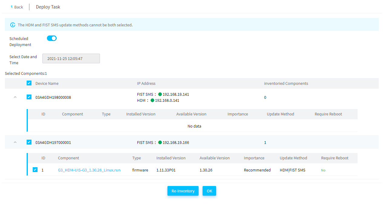
7. As shown in Figure 157, after the deployment is completed, click Logs to view the deployment logs.
Figure 157 Deployment completed
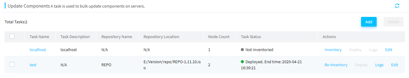
8. As shown in Figure 158, enter the task deployment log page to view the component deployment results.
Figure 158 Task deployment logs
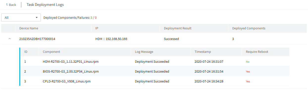
Edit a task
1. In the navigation pane, select Menu > Deployment > Update Components.
2. Click Edit in the Actions column for the task to edit. In the dialog box that opens, perform the following steps:
a. In the Basic Info area, edit the task description.
b. In the Select Nodes area, select the nodes to be edited.
c. In the Repository area, select the repository to be assigned to the task from the Repository list.
d. In the Installation Options area, edit HDM/BIOS firmware configuration retention policies and the server restart policy.
3. Click OK.
Troubleshooting issues
No result displayed after task inventorying
Symptom
The system does not display the inventorying result when a task is inventoried for component update.
Cause
· The user does not run FIST as an administrator or root user.
· The firewall is not disabled in the operating system where the FIST server or FIST SMS runs.
Action
1. Run FIST as an administrator or root user. In Windows, right-click the FistLaunch_x64.bat file and select Run as administrator. In Linux, switch to the root user to run FIST.
2. Verify that the firewall is disabled in the operating system. If the firewall is enabled, disable the firewall and perform task inventorying again.
3. If the issue persists, contact Technical Support.
Current component version displaying as Unknown during task deployment for component update
Symptom
The current component is displayed as Unknown during task deployment for component update.
Cause
FIST fails to obtain the current server component version.
Action
No action is required. After deployment, you can examine the component version to identify whether the component update is successful.
Insufficient HDM user privilege
Symptom
Deployment failed for component update and the reason is that the HDM user does not have the privilege.
Cause
The HDM user of the servers does not have administrator privilege.
Action
Edit devices on the Server List page, and specify the new username and password of the HDM user as an administrator.
Software requirements not met in the operating systems
Symptoms
Deployment failed for component update, and a message indicates that the dependent software is not installed.
Cause
When you update components through FIST SMS, the dependent software in the operating system for the update is not installed, for example, GNU Compiler Collection (GCC).
Action
Install the software as instructed in the operating system where FIST SMS resides.
FIST cannot connect to servers
Symptom
Deployment failed for component update, and the reason is that a login failure occurred.
Cause
· An error occurred on network connection between the FIST server and HDM.
· The username or password is incorrect for login to HDM or FIST SMS.
Action
1. Verify that the servers are powered on correctly and the network connection is normal
2. View server information, and edit devices on the server list to specify correct username and password for as required.
Component deployment failed
Symptom
Deployment failed for component update, but no reason is displayed.
Cause
· The Python environment is not installed when you update drive firmware through FIST SMS.
· Firmware of some components has protection mechanism and does not support repeated update, for example, PMem 200 memory, and Rack_NIC-360T-B2 and Rack_NIC-560F-B2 network adapters.
· For firmware or driver update through FIST SMS, the update fails because the original driver version of components is too low.
Action
1. If deployment failed on drive firmware, verify that Python is installed in the operating system and the Python environment is normal.
|
|
IMPORTANT: If multiple Python versions are available, execute the ln –s or update-alternatives command to specify the default Python version. For example: · ln -s /usr/local/python3/bin/python3.7 /usr/bin/python. · sudo alternatives --set python /usr/bin/python3. |
2. Restart the operating system to make the last deployment take effect.
3. Identify the driver version of the components that failed deployment, and manually update the driver as needed.
4. If the issue persists, contact Technical Support.
Update the firmware
|
|
TIP: · To use this feature, you must add HDM server nodes to FIST first. For more information, see "Add, edit, or delete servers." · Do not perform template application, component update, or other operations on a server while firmware update is in progress on the server. · Before upgrade, as a best practice to ensure that the firmware can be upgraded to the expected version, first check the related firmware version information in the REPO. |
FIST supports the following methods to update the firmware:
· Offline firmware update—This method automatically updates the firmware on multiple servers in bulk by using the REPO (containing the LiveCD system) uploaded to FIST. This method will affect the operation of the original operating system.
· HDM out-of-band firmware update—This method updates the REPO by using HDM out-of-band management and automatically accesses iFIST to perform firmware update at the next server startup.
Update the firmware offline
About this task
You can perform unattended firmware update on multiple servers in bulk.
Before you use this function, upload the REPO (ISO file) containing the LiveCD system to FIST. For information about the operation procedure, see "Manage images."
Restrictions and guidelines
· To ensure successful update, verify that the target server does not have an image mounted through KVM and its USB port is not connected to the USB drive.
· To guarantee the firmware update speed, use the HDM dedicated port as a best practice. If the shared network port is used, set the rate of the corresponding NIC on the FIST server to 100 Mbps.
· Keep the network stable during the update process.
· To abort the ongoing update process on a server and start a new update process, select the server, and then click Cancel Update first.
· An HDM server node in abnormal state cannot be rebooted.
· FIST can show the firmware update progress and result for a server only when a repository is used for the update and the server runs HDM 2.11 or later.
Procedure
1. In the navigation pane, select Menu > Deployment > Firmware Update > Offline Firmware Update.
2. Select the target servers, and then click Update Firmware.
To quickly filter out the target server, you can use the label or enter a keyword in the search area.
3. In the dialog box that opens, select the image file for the update, and then click OK.
4. (Optional.) To view the firmware update progress of a server, click the H5 KVM link in the Actions column for the sever.
5. (Optional.) After the update is complete for a server, click the Update Finished or Update Failed link in the Update Status column for the server to view the update result.
6. Some firmware products require a reboot to take effect. Select the updated servers and click Reboot to reboot the servers.
Figure 159 Offline firmware update
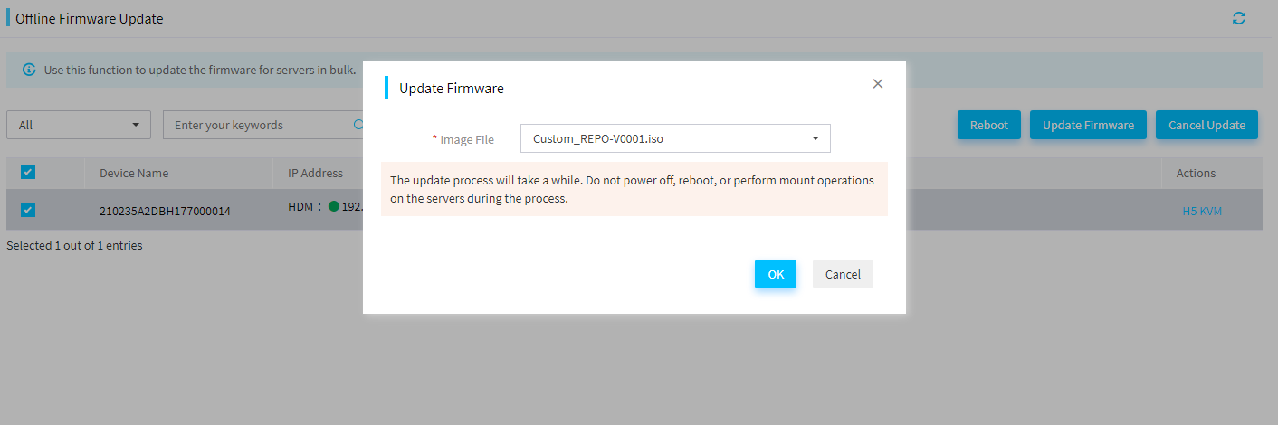
Update the firmware by using HDM out-of-band management
About this task
You can use HDM out-of-band management to update the REPO on multiple servers in bulk.
Before you use this function, upload the REPO to FIST. For information about the operation procedure, see "Manage images."
To use this feature, the following requirements must be met:
· FIST is used together with HDM and iFIST.
· FIST is in FIST-2.32 or later versions.
· HDM is in HDM-2.52 or later versions.
· iFIST is in iFIST-1.32 or later versions.
Procedure
1. In the navigation pane, select Menu > Deployment > Firmware Update > HDM Out-of-Band Firmware Update.
Figure 160 HDM Out-of-Band Firmware Update
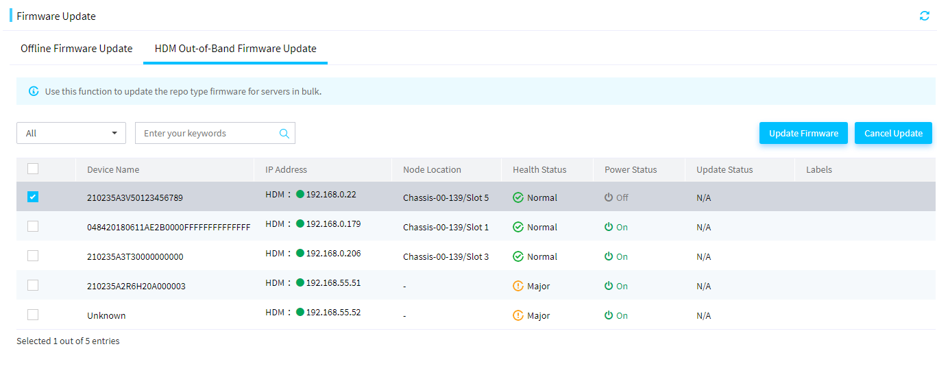
2. Select the target servers and then click Update Firmware. In the dialog box that opens, select the image file for the update, the server restart method after firmware update, and an update option.
To search for the target servers, select a label, and enter a keyword in the search box.
Figure 161 Configuring parameters
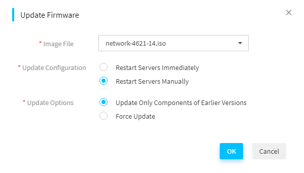
3. Click OK.
4. To cancel ongoing firmware update operations on servers, select the target servers and then click Cancel Update. In the confirmation dialog box that opens, click OK.
If a server is verifying the file for update, you cannot cancel the ongoing firmware update operation on the server.
Configure monitoring
View reports
The report feature collects and summarizes information about local users and managed servers.
View local users
About this task
Perform this task to view the summary information about all FIST users.
Procedure
1. In the navigation pane, select Menu > Monitor > Reports.
2. Click the Local User tab. You can view the statistics about local users.
Figure 162 Local user
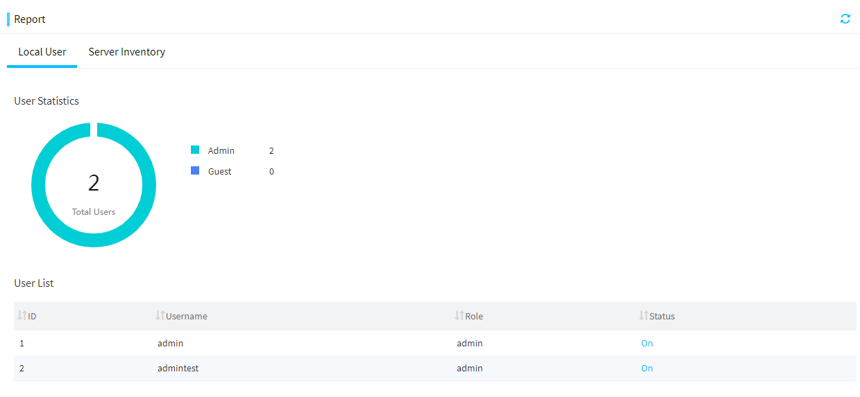
View the server inventory
About this task
Perform this task to export summary information about the servers managed by FIST to an Excel or PDF file and save the file on the FIST client locally.
A PDF file can be used as an inspection report. You can add inspector and customer information. The PDF file can also provide the summary of all H3C-proprietary servers and information about each H3C-proprietary server.
Procedure
1. In the navigation pane, select Menu > Monitor > Reports.
2. Click the Server Inventory tab. You can view the server statistics by healthy status, product name, processor core count, HDM version, and BIOS version, and view top 5 server statistics in pie charts.
You can also view the server inventory list, including serial number, product name, IP address, BIOS boot options, BIOS boot mode, processor model, memory, and firmware.
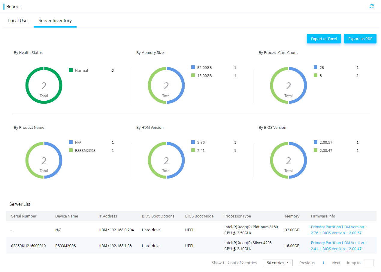
3. Click Export as Excel in the upper right corner to export the server inventory information to an Excel file.
4. Click Export as PDF in the upper right corner. In the dialog box that opens, configure the following settings, and then click OK to export the server inventory information to a PDF file:
¡ Select at least one value for the Health Status field.
¡ Select at least one PDF export model.
¡ Select server modules for details export.
¡ Enter inspection information, including the inspector name (optional), phone number (optional), customer organization name (optional), and customer organization address (optional).
View the chassis inventory
About this task
Perform this task to export summary information about chassis managed by FIST to an Excel or PDF file and save the file on the FIST client locally.
The chassis inventory file can be used as a routine inspection report. You can add inspector and customer information to the report.
Procedure
1. In the navigation pane, select Menu > Monitor > Reports.
2. Click the Chassis Inventory tab. You can view the chassis statistics by sub-system status and blade server model.
You can also view the chassis inventory list. The list displays the device name, IP address, chassis status, power redundancy mode, current power (W), power cap (W), dynamic power saving mode, location, and asset tag.
3. To export the inventory, select the target chassis, click Export, and then select Export as PDF or Export as Excel.
4. In the dialog box that opens, enter an inspector name (optional), phone number (optional), customer organization name (optional), and customer organization address (optional), and then click OK.
View operation logs
About this task
The operation log feature logs operations that a user performs on the FIST Web interface. The operation log information includes the operation user, operation timestamp, and operation result. You can set filters to view only operation logs that match the filters.
Procedure
1. In the navigation pane, select Menu > Monitor > Operation Logs.
The Operation Logs page displays all operation logs.
Figure 164 Operation Logs page
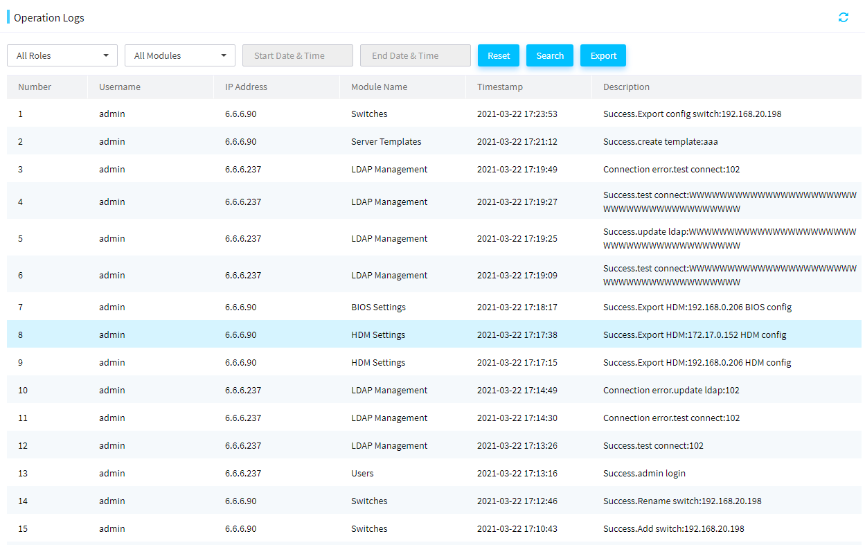
2. To filter operation logs, set the filter items.
¡ To filter operation logs by user role, select a role.
¡ To filter operation logs by module, select a module.
¡ To filter operation logs by time, select a time range.
3. Click Search. This page displays only operation logs that match all the specified filter items.
4. To clear the search criteria and display all logs, click Reset.
5. Click Export to download all operation logs in CSV format to the device.
Configure alarm forwarding
This module allows you to perform the following tasks to monitor the operating status of managed servers:
· Send server event logs to the specified recipients in emails.
· Listen to SNMP traps from the managed servers and send the traps to designated hosts.
· FIST supports sending the SNMP traps of the managed servers to users through WeCom, SMS, and voice messages.
Prerequisites
To use this feature, you must add HDM server nodes to FIST first. For more information, see "Add, edit, or delete servers."
Configure listening settings
About this task
Perform this task to listen to and receive SNMP traps sent from the managed servers to help users monitor the server status.
FIST will apply the listening settings to all the managed servers so the servers will send SNMP traps to FIST. Then, FIST will record all the received SNMP traps in the Activity Logs page.
Restrictions and guidelines
· Make sure the listening IP address is on the same network segment as the HDM IP address of the managed server.
· The listening settings take effect on HDM of the managed server only if the HDM user has the administrator user role.
Procedure
1. In the navigation pane, select Menu > Monitor > Alarm Forwarding.
Figure 165 Alarm Forwarding page
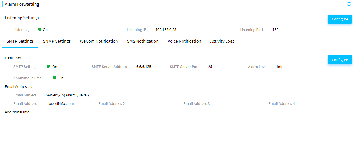
2. Click Configure. In the dialog box that opens, perform the following steps:
a. Select On for Listening Settings.
b. Select a listening IP address.
c. Set the listening port number.
Figure 166 Configuring listening settings
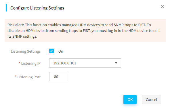
3. Click OK.
4. Click the Activity Logs tab. You can view SNMP traps that managed servers sent to FIST.
5. (Optional.) You can view the specified IP addresses of the SNMP trap servers on the Configuration > Alarm Settings > SNMP trap page on HDM.
Configure SMTP settings
About this task
Perform this task to implement the following functions:
· Send event logs of the managed servers to concerned users to monitor the operating status of the servers.
· Monitor the health status of the managed servers and then send alarm emails to concerned users to notify the health change.
Prerequisites
· Obtain the IP address and port number of the SMTP server, and make sure the FIST server can correctly communicate with the SMTP server.
· For the FIST server to correctly send alarm emails, enable the alarm listening feature and set the listening IP address and listening port number. For more information, see "Prerequisites."
Restrictions and guidelines
· When a managed server generates an event log with a severity equal to or higher than the severity specified on FIST, the recipients can receive an alarm notification email.
· If severity levels of alarms to be sent are specified on both FIST and HDM, only alarms that match both the severity levels will be sent.
Procedure
1. In the navigation pane, select Menu > Monitor > Alarm Forwarding.
2. Click the SMTP Settings tab. In the dialog box that opens, perform the following steps:
a. Select On for SMTP Settings.
b. Enter the IP address of the SMTP server.
c. Enter the port number of the SMTP server. The default port number is 25.
d. Select whether to enable Anonymous Email. If this feature is not enabled, you must specify the encryption protocol, sender username, and sender password.
e. Select the alarm level.
f. To customize the IP address, HDM host name, alarm level, or alarm event description in the email subject, enter the ${ip}, ${HDM_HostName}, ${level}, or ${event} field. If you do not enter an email subject, the default email subject will be used.
g. Add the email addresses of alert recipients.
Figure 167 Configuring SMTP settings
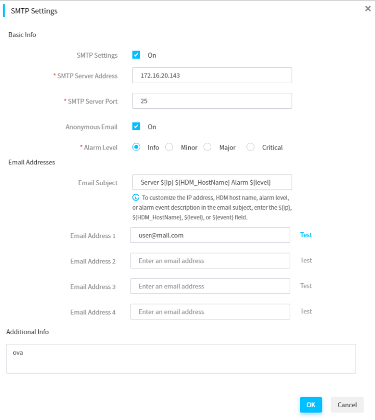
3. In the Additional Info field, enter the additional information to append to each email to be sent.
4. Click OK.
5. (Optional.) To test whether a recipient can receive an alarm, click Test for the email address of the recipient.
Configure SNMP settings
About this task
This feature is available in FIST 2.00.17 and later.
Perform this task to add SNMP users and target hosts to receive SNMP traps (trap destinations) from the managed servers.
FIST will receive SNMP traps that have a severity level equal to or higher than the specified level from the managed servers and then forward the traps to the target trap hosts.
Procedure
1. In the navigation pane, select Menu > Monitor > Alarm Forwarding.
2. Click the SNMP Settings tab.
Figure 168 SNMP Settings page
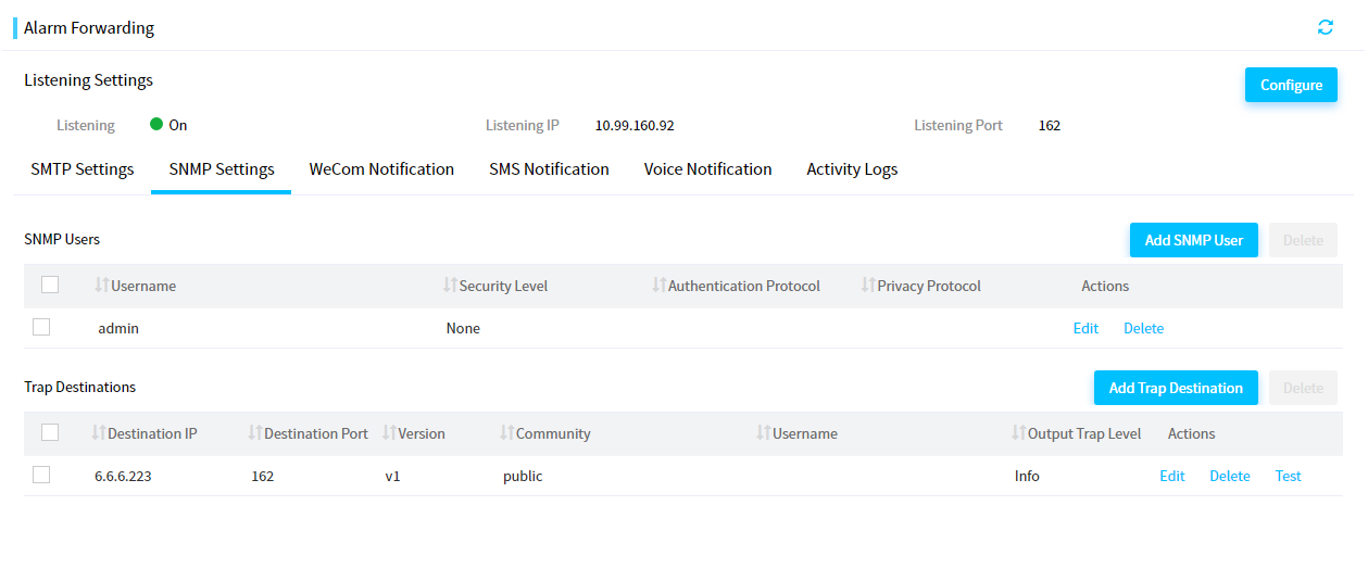
3. (Optional.) To send SNMPv3 traps, click Add SNMP User to add an SNMP user as follows:
a. Enter a username.
b. Select a security level.
c. Select an authentication protocol for the user.
d. Enter the authentication password for the user.
e. Click OK.
Figure 169 Adding an SNMP user
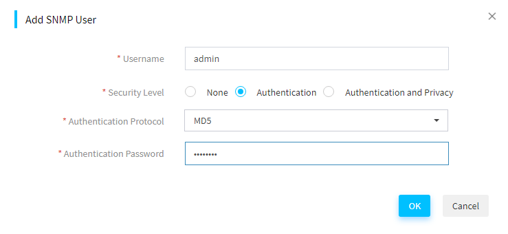
4. Click Add Trap Destination, and configure the trap destination as follows:
a. Enter the destination IP address.
b. Enter the destination port number. The default destination port number is 162.
c. Select an SNMP version.
d. Enter the community.
e. Select an output trap level.
Figure 170 Adding a trap destination
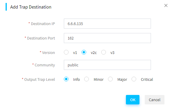
5. Click OK.
6. (Optional.) To send a test alarm message to a trap destination, click Test in the Actions column of the trap destination.
Configure WeCom notification
About this task
This feature is available in FIST 2.34 and later.
Perform this task to configure WeCom notification. With this feature enabled, the SNMP traps of the managed servers will be sent to the specified WeCom application.
Restrictions and guidelines
Only the WeCom administrator can obtain the WeCom parameters. To obtain WeCom parameters, see the related WeCom document.
Access to the Internet through HTTPS is required to use this function. Please configure DNS and proxy as required. For more information, see "Configure DNS" and "Configuring proxy settings."
Procedure
1. In the navigation pane, select Menu > Monitor > Alarm Forwarding.
2. Click the WeCom Notification tab.
Figure 171 Configuring WeCom notification
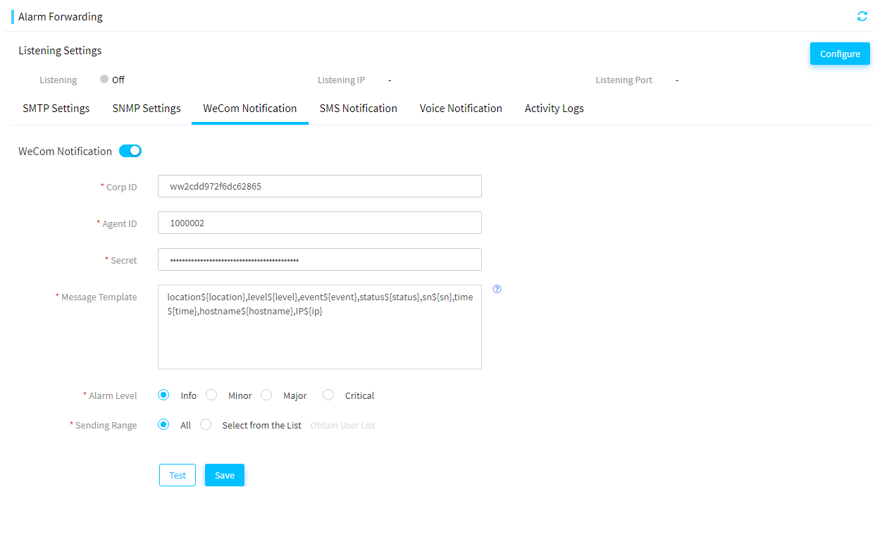
3. Enable WeCom notification, enter the required parameters, and click Save.
4. (Optional.) Click Test to test whether a notification can be sent to the specified WeCom application.
Configure SMS notification
About this task
This feature is available in FIST 2.34 and later.
Perform this task to configure SMS notification. With this feature enabled, the SNMP traps of the managed servers will be sent to the specified receiver through SMS.
Only Emay is supported in the current software version. For information about the SMS service content, contact Emay. For Emay, mainland China SMS belong to a different service from SMS provided in Hongkong, Macao and Taiwan, China, and other countries or regions. Do not mix the customer IDs of different services. For other functions, contact Emay customer service.
Restrictions and guidelines
Access to the Internet through HTTPS is required to use this function. Please configure DNS and proxy as required. For more information, see "Configure DNS" and "Configuring proxy settings."
Procedure
1. In the navigation pane, select Menu > Monitor > Alarm Forwarding.
2. Click the SMS Notification tab.
Figure 172 Configuring SMS notification
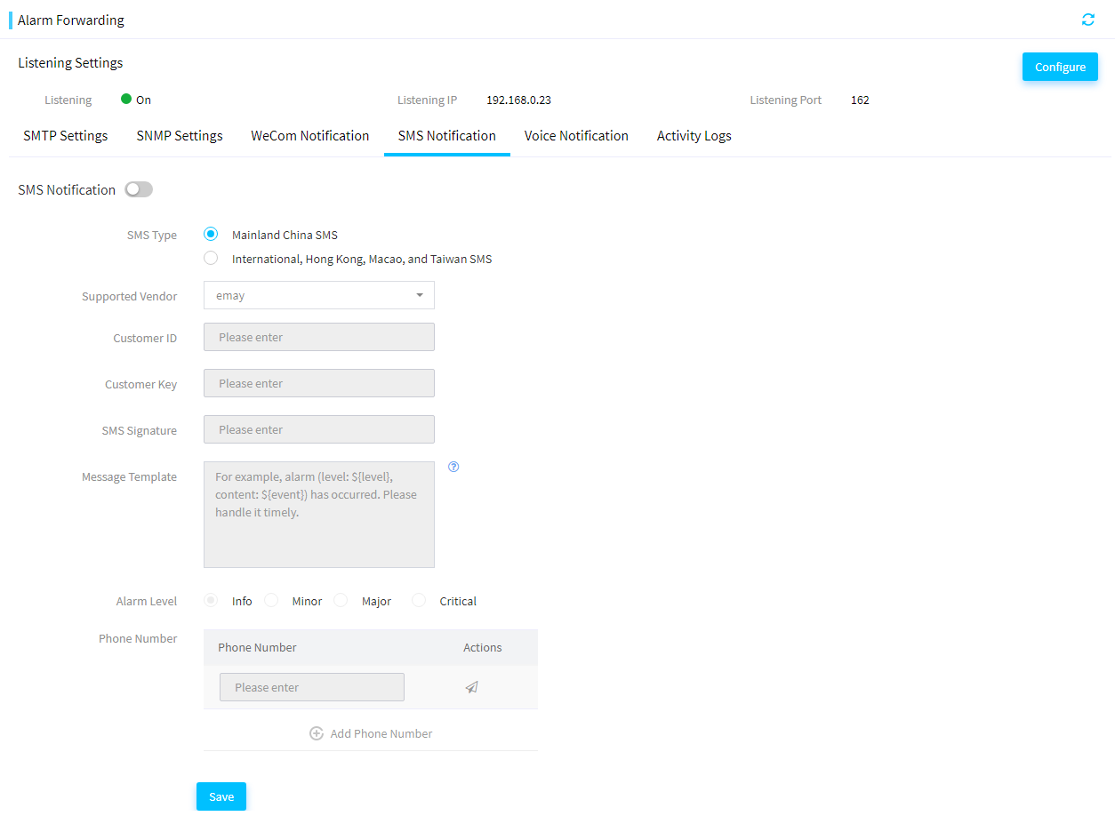
3. Enable SMS notification and enter the required parameters.
4. Click Add Phone Number and enter phone numbers.
5. (Optional.) Click the ![]() icon for a phone
number to test whether a SMS notification can be sent to the phone number.
icon for a phone
number to test whether a SMS notification can be sent to the phone number.
6. (Optional.) Click the ![]() icon
for a phone number to delete the phone number for receiving SMS notifications.
icon
for a phone number to delete the phone number for receiving SMS notifications.
7. Click Save.
Configure voice notification
About this task
This feature is available in FIST 2.34 and later.
Perform this task to configure voice notification. With this feature enabled, the SNMP traps of the managed servers will be sent through voice messages.
Restrictions and guidelines
To send voice messages successfully, notify Emay of the voice message template before using this feature. For more information, contact Emay customer service.
Access to the Internet through HTTPS is required to use this function. Please configure DNS and proxy as required. For more information, see "Configure DNS" and "Configuring proxy settings."
To edit the voice message template, notify Emay of the updated template and obtain the new template ID.
Procedure
1. In the navigation pane, select Menu > Monitor > Alarm Forwarding.
2. Click the Voice Notification tab.
Figure 173 Configuring voice notification
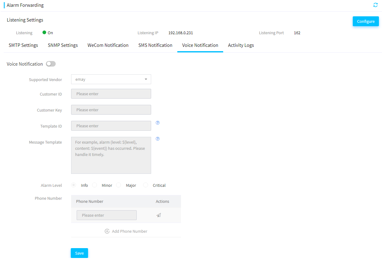
3. Enable voice notification and enter the required parameters.
4. Click Add Phone Number and enter phone numbers.
5. (Optional.) Click the ![]() icon
for a phone number to test whether a voice notification can be sent to the
phone number.
icon
for a phone number to test whether a voice notification can be sent to the
phone number.
6. (Optional.) Click the ![]() icon
for a phone number to delete the phone number for receiving voice
notifications.
icon
for a phone number to delete the phone number for receiving voice
notifications.
7. Click Save.
View activity logs
About this task
This module allows you to view SNMP traps sent to FIST by managed HDM server nodes.
The FIST host can receives SNMP traps only when the alarm listening feature is enabled.
Procedure
1. In the navigation pane, select Menu > Monitor > Alarm Forwarding.
2. Click the Activity Logs tab. The page displays all SNMP traps that FIST received.
3. To filter the SNMP traps, select a severity level, time range, or both, or enter a source or description in the search box.
Figure 174 Filtering SNMP traps
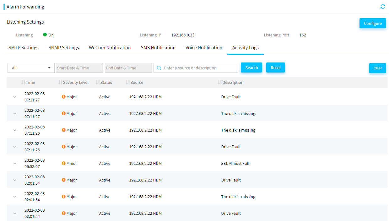
4. Click Search. The page displays only SNMP traps that match the filter criteria.
Manage energy efficiency and prediction (G6 servers)
Energy efficiency analysis
This module allows you to identify low-load or idle servers and transfer extra services to these servers or power off these servers to optimize the power consumption of the entire data center. This module supports detection only on NVIDIA GPUs. You must install NVIDIA GPU drivers in advance.
This feature is available only when FIST runs on a VM.
Configure inlet temperature analysis
Perform this task to view server temperature summary information, identify servers with temperature anomalies, and power on or power off servers in batch.
View inlet temperature information
1. In the navigation pane, select Menu > Energy and Prediction > Energy Efficiency Analysis > Inlet Temperature Analysis.
2. View inlet temperature information for servers.
Figure 175 Inlet temperature analysis
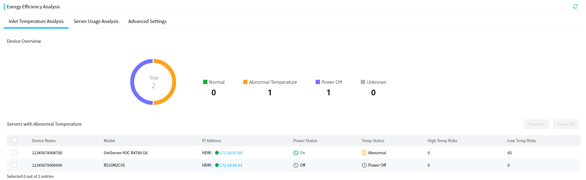
Power on servers in batch
1. Select servers from the Servers with Abnormal Temperature list.
2. Click Power On. In the dialog box that opens, confirm devices to be powered on, agree to the operation consequence notice, and click OK.
Figure 176 Powering on servers in batch
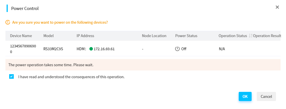
Power off servers in batch
1. Select servers from the Servers with Abnormal Temperature list.
2. Click Power Off. In the dialog box that opens, confirm devices to be powered off, agree to the operation consequence notice, and click OK.
Figure 177 Powering off servers in batch
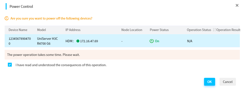
Configure server usage analysis
Perform this task to view server summary information, abnormally loaded servers, and server distribution by load status. You can power on and power off abnormally loaded servers in batch, configure power capping, and view server load trend in the past day.
View server usage information
1. In the navigation pane, select Menu > Energy and Prediction > Energy Efficiency Analysis > Server Usage Analysis.
2. View server usage information.
Figure 178 Server usage analysis
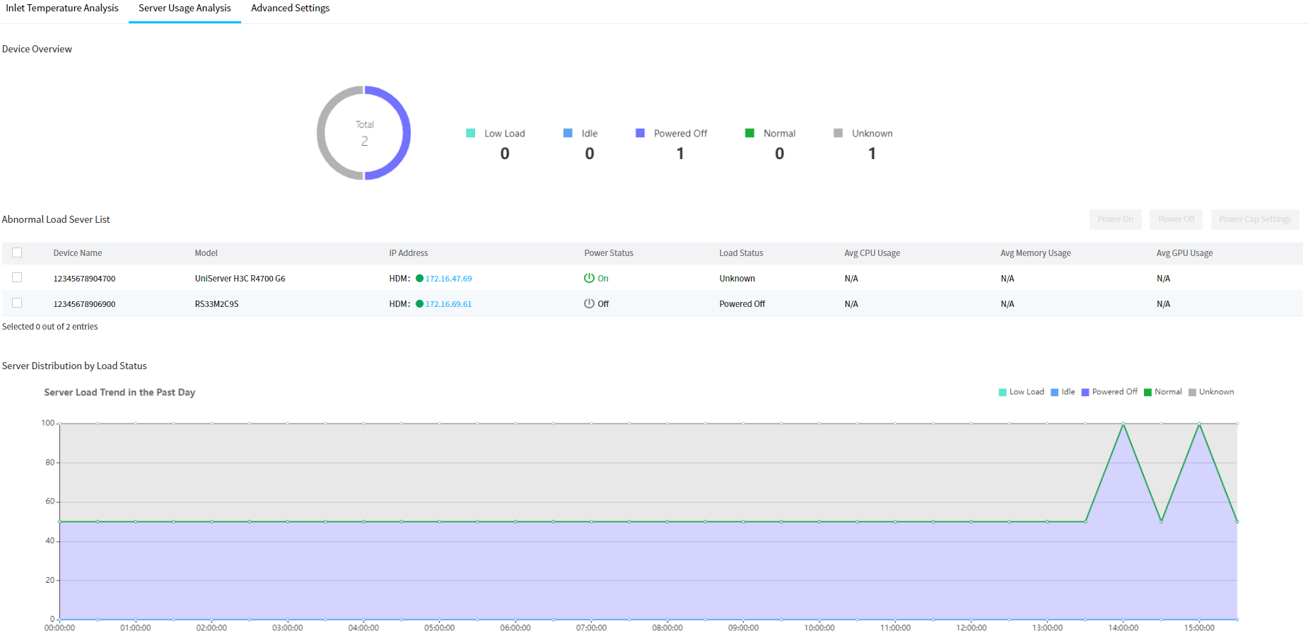
Power on servers in batch
1. Select servers from the abnormally loaded server list.
2. Click Power On. In the dialog box than opens, confirm devices to be powered on, agree to the operation consequence notice, and click OK.
Power off servers in batch
1. Select servers from the abnormally loaded server list.
2. Click Power Off. In the dialog box than opens, confirm devices to be powered off, agree to the operation consequence notice, and click OK.
Configure power cap settings
1. Select a server from the abnormally loaded server list.
2. Click Power Cap Settings for the server. View and configure power capping parameters.
3. Click OK.
Configure advanced settings
Perform this task to configure parameters for server usage analysis and inlet temperature analysis.
Procedure
1. In the navigation pane, select Menu > Energy and Prediction > Energy Efficiency Analysis > Advanced Settings.
2. Enable server usage analysis. Select CPU, GPU, and Memory for Set Thresholds as needed and specify respective values in the CPU Usage Lower Limit (%), GPU Usage Lower Limit (%), Memory Usage Lower Limit (%), and Duration (day) fields for idle and low-load servers.
3. Enable inlet temperature analysis. Select ASPMEAE AI or Custom for Set Temp Range. If you select ASPMEAE AI, specify an AI type (A1, A2, A3, or A4) and configure the High Temp Count Limit, Low Temp Count Limit, and Duration. If you select Custom, configure parameters such as the temperature range.
4. Click Save.
Figure 179 Configuring advanced settings
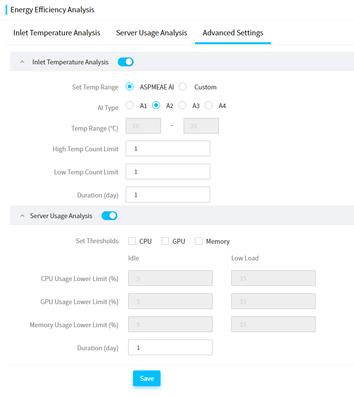
Perform one-key power consumption limit
About this task
When the power supply system in the equipment room fails, the emergency power supply will be enabled. To prolong the operation time with the emergency power supply, you can use this feature to limit the power consumption of servers to a low level. The operation might affect server performance.
Procedure
1. In the navigation pane, select Menu > Energy and Prediction > One-Key Power Consumption Limit.
Figure 180 One-Key Power Consumption Limit page
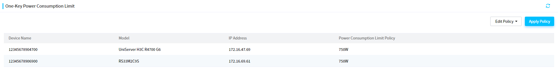
2. Select Default or Custom from the Edit Policy field.
¡ If you select Default, the system uses the default power consumption limit policies. To save the settings, click Save. To cancel the settings, click Cancel.
¡ If you select Custom, you can specify Power Off, No Action, or Custom in the Power Consumption Limit Policy column for each server. If you specify Custom for a server, configure the power cap value and select whether to enable shutdown on capping failure. To save the settings, click Save. To cancel the settings, click Cancel.
Figure 181 Selecting a policy editing method
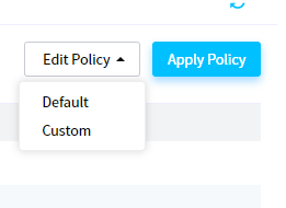
Figure 182 Selecting the default policy
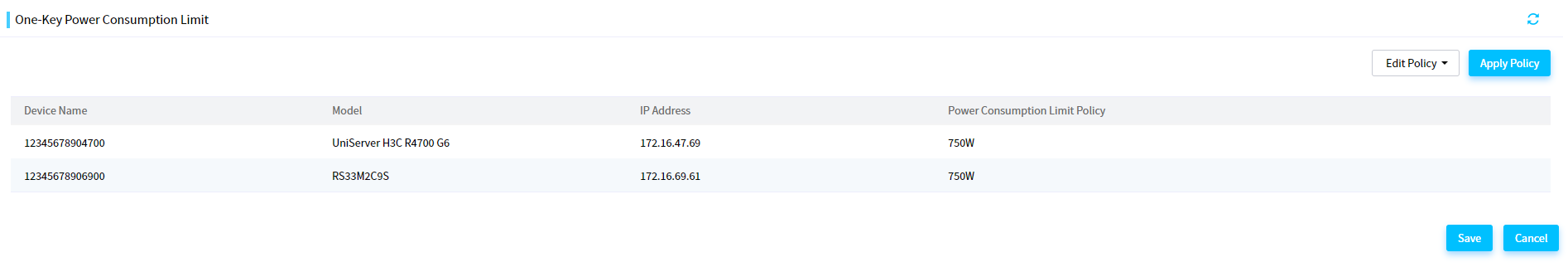
Figure 183 Customizing a policy
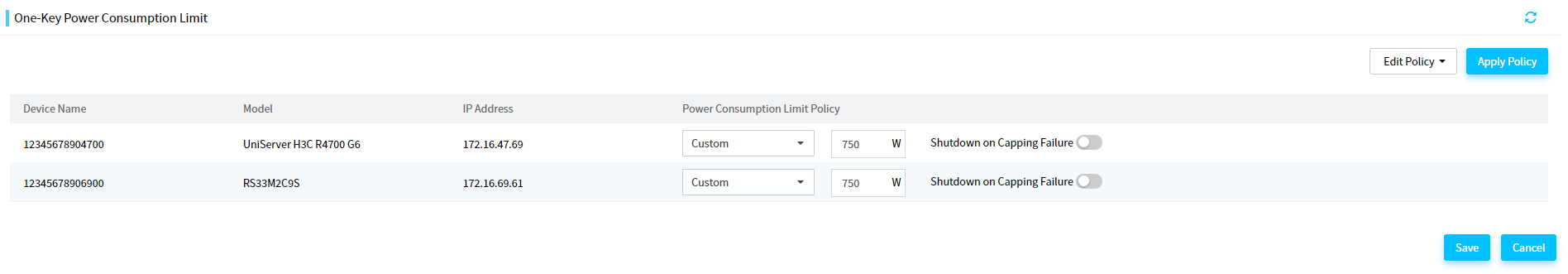
3. Click Apply Policy. In the dialog box that opens, enter YES to confirm the operation and then click OK.
Figure 184 Deploying the power policy
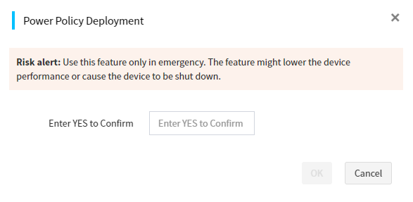
Configure tools
Configure the DHCP server
|
|
IMPORTANT: Before starting the DHCP server, first check the current LAN configuration, and make sure there are not multiple DHCP servers, which will cause network failure. |
This module allows you to use a DHCP server to automatically allocate an IP address or statically bind an IP address to each client on the same LAN. The IP address can be as an HDM management IP address or system IP address. FIST supports the following IP address allocation methods:
· Dynamic method—When a client requests an IP address from the DHCP server, the DHCP server automatically selects an IP address from the IP pool and assigns the IP address to the client.
· Static method—Manually binds an IP address to a client. When the client requests an IP address from the DHCP server, the DHCP server assigns the bound IP address to the client.
Restrictions and guidelines
The DHCP server feature is exclusive with the DHCP feature in PXE deployment. You cannot configure the two features at the same time because port conflict will occur.
Configure the DHCP server settings
About this task
Perform this task to configure the settings for the DHCP server. You can use the DHCP server to dynamically assign IP addresses to DHCP clients.
Restrictions and guidelines
· If a large number of DHCP clients exist on the network, set the lease time to a greater value.
· For the DHCP server service to start successfully, make sure port number 67 is not being used by another service (for example, dnsmasq).
Procedure
1. In the navigation pane, select Menu > Tools > DHCP Server.
2. Click DHCP Service. In the dialog box that opens, perform the following steps:
a. Select On for DHCP Server.
b. Select the first IP address from the Server IP list.
c. Enter the start IP address and end IP address.
d. Enter the lease time.
e. Enter the gateway address. This field is optional.
Make sure the start IP address and end IP address must be on the same network subnet as the DHCP server.
Figure 185 Configuring the DHCP server
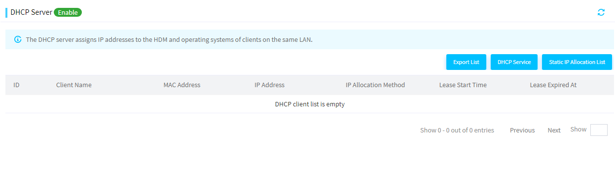
3. Click OK.
View the DHCP client information
About this task
Perform this task to view information about DHCP clients that obtain IP addresses from the DHCP server.
Procedure
1. In the navigation pane, select Menu > Tools > DHCP Server.
2. Click DHCP Service. The page displays information about all DHCP clients.
Figure 186 DHCP client information
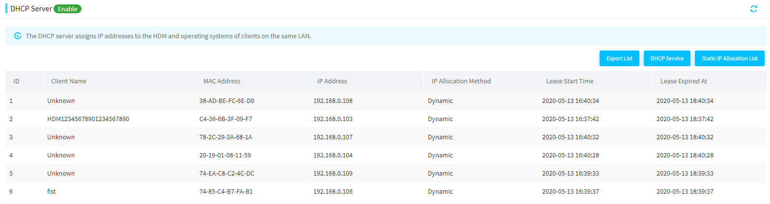
3. (Optional.) If the IP address of a DHCP client is statically assigned by the DHCP server, the Lease Expired At field of this client displays Release. You can click Release to unbind the IP address and the MAC address of the client.
Parameters
· Client Name: Name of a DHCP client.
· MAC Address: MAC address of the DHCP client.
· IP Address: IP address that the DHCP client obtains from the DHCP server.
· IP Allocation Method: Method through which the DHCP client obtains the IP address. Options include:
¡ Dynamic: The DHCP server dynamically selects the IP address from the IP address range to assign to the DHCP client.
¡ Static: The DHCP server statically binds the IP address with the DHCP client.
· Lease Start Time: Time when the DHCP client obtained the IP address.
· Lease Expired At: Time when the IP address expires.
Configure static IP allocation
About this task
This feature allows you to view information about static IP addresses assigned to DHCP clients, to assign a static IP address to a DHCP client, and to release a static IP address.
Restrictions and guidelines
Static IP allocation takes effect only when the DHCP server is enabled.
Procedure
1. In the navigation pane, select Menu > Tools > DHCP Server.
2. Click Static IP Allocation List. The dialog box that opens displays all static IP addresses that have been assigned to DHCP clients.
Figure 187 Static IP Allocation List page
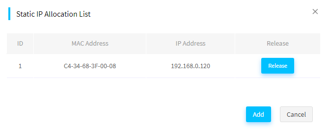
3. (Optional.) To reclaim the IP address assigned to a DHCP client, click Release. In the dialog box that opens, click OK.
4. (Optional.) Click Add to assign a static IP address to a DHCP client. In the dialog box that opens, enter a MAC address and an IP address.
Figure 188 Configuring a static IP allocation
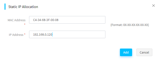
5. Click Add.
Parameters
· MAC Address: MAC address of a DHCP client. The MAC address cannot be a broadcast or multicast MAC address.
· IP Address: IP address statically assigned to the DHCP client. The IP address has the following restrictions:
¡ The IP address must be on the same network segment as the DHCP server but cannot be the same as the DHCP server address.
¡ The IP address can be out of the IP address range specified for the DHCP server.
¡ The IP address cannot be a multicast or broadcast address.
¡ The IP address must be an unused IP address.
Export the IP allocation list
About this task
Perform this task to export the list of IP addresses that have been assigned to DHCP clients to a local file.
Procedure
1. In the navigation pane, select Menu > Tools > DHCP Server.
2. Click Export List. FIST exports the statically assigned IP addresses to an EXCEL file.
Configure PXE deployment
About this task
|
|
IMPORTANT: · As a best practice, do not enable the PXE function if you do not need to deploy operating systems through PXE. · If another device is on the same network as FIST and the device is configured to obtain an IP address dynamically through DHCP, enabling the PXE function might cause the IP address of the device to change. To avoid affecting other devices on the network, you must isolate the FIST network and the network of devices for PXE deployment. |
PXE deployment allows a PXE client to download the OS it requires over the network and then automatically boot and install the OS.
The PXE deployment process is as follows:
1. A PXE client boots from its own PXE Ethernet adapter, requests an IP address and the location of the boot file from the DHCP server on the network.
2. The DHCP server returns an IP address and the location of the boot file to the PXE client.
3. The PXE client downloads the boot file from the TFTP server on the network and executes the boot file. Based on the execution result of the boot file, the PXE client loads the kernel and file systems from the TFTP server.
4. The PXE client enters the OS installation screen and installs the OS through HTTP.
For RedHat and CentOS installed by using this feature, the default root password is Password@. For other Linux OSs installed by using this feature, the default root password is 123456.
The following OSs support PXE deployment:
· CentOS 6.8 (64 bit)
· CentOS 7.2 (64 bit)
· CentOS 7.4 (64 bit)
· Red Hat Enterprise Linux 6.3 (64 bit)
· Red Hat Enterprise Linux 6.8 (64 bit)
· Red Hat Enterprise Linux 7.2 (64 bit)
· Red Hat Enterprise Linux 7.4 (64 bit)
· Red Hat Enterprise Linux 7.5 (64 bit
Restrictions and guidelines
· A PXE-capable Ethernet adapter is required on the PXE client.
· The PXE client obtains an IP address through the DHCP feature in PXE deployment.
· The IP range does not include a broadcast address.
· The IP addresses in the IP range do not conflict with existing IP addresses on the network.
· PXE deployment uses port numbers 67 and 69 as the DHCP service and the TFTP service, respectively. For PXE deployment to start successfully, make sure port numbers 67 and 69 are not used by other services.
· The DHCP feature in PXE deployment is exclusive with the DHCP server feature. You cannot configure the two features at the same time because port conflict will occur.
· When you install an OS to a blade server through PXE deployment, follow these restrictions and guidelines:
¡ If the iPXE boot loader is used, PXE deployment will fail for a server installed with a mezzanine card and with the legacy boot mode. In this case, use the PXELINUX or GRUB2 boot loader.
¡ The start IP address in the IP range must be on the same subnet as the IP address of network port vmng on the AE module.
¡ The IP range does not include the IP address of network port vmng on the AE module.
¡ IP addresses in the range of 192.250.0.0 through 192.250.255.255 are reserved for internal use. Do not include these IP addresses in the IP range.
Procedure
1. In the navigation pane, select Menu > Tools > PXE Deployment.
Figure 189 PXE deployment page
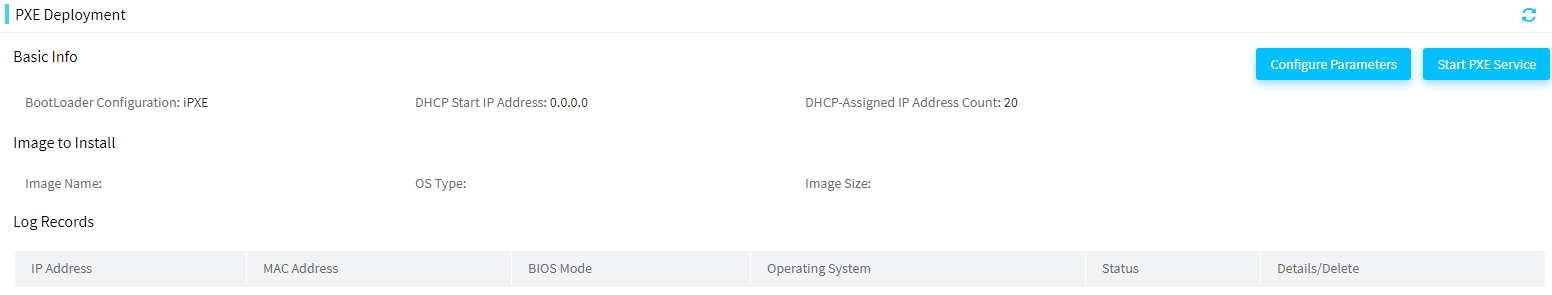
2. Click Configure Parameters, and configure PXE deployment parameters as follows:
a. Select a boot loader configuration mode.
b. Enter the DHCP start IP address and the DHCP-assigned IP address count.
During PXE deployment, the DHCP server will assign an IP address in this range to a server. After the OS installation, the server will use this IP address as the system IP address.
c. Select an image from the image list.
Figure 190 Configuring PXE deployment parameters
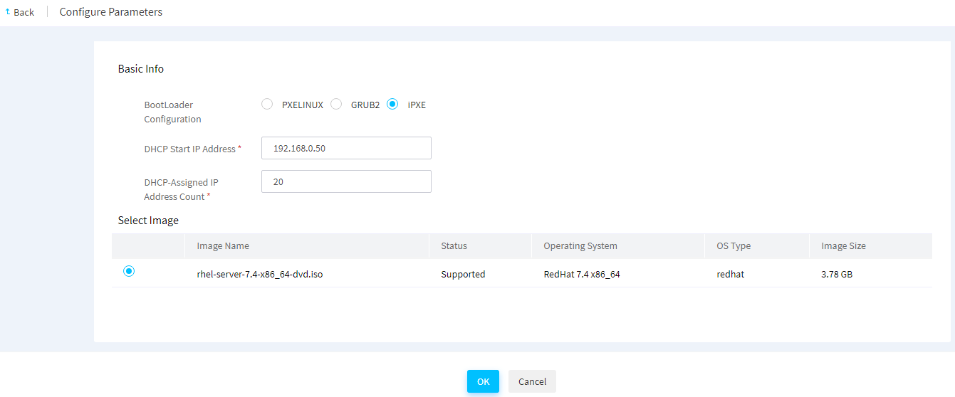
3. Click OK.
Parameters
· BootLoader Configuration: Boot loader of the OS to be installed on a server.
¡ PXELINUX—Derived from SysLinux, PXELINUX enables a client to boot from a network server.
¡ GRUB2—Also referred to GNU GRUB. GRUB2 is a multi-OS boot loader from the GNU project. GRUB2 allows a client to have multiple OSs simultaneously and boot from an expected OS.
¡ iPXE—Provides enhanced PXE implementations. It is compatible with multiple protocols. As a best practice, use iPXE.
· DHCP Start IP Address: First IP address of the IP pool used for IP assignment.
· DHCP-Assigned IP Address Count: Number of IP addresses in the IP pool used for IP assignment.
Configure PXE OS installation parameters
A KS file contains the parameters used by PXE to install the OS for servers, including root password, username, user password, partition settings, software package settings, and language.
FIST provides a default KS file that contains PXE-defined default parameters and a custom KS file that allows users to edit the parameters and restore the default settings.
In the current software version, FIST supports KS files only for RedHat and CentOS.
Restrictions and guidelines
· The custom KS file is automatically generated when the system uploads the OS software image. The parameter settings in the custom KS file are the same as those in the default KS file.
· For an OS in use, you cannot edit the custom KS file or restore the default settings of the KS file.
· During configuration restoration, FIST will restore the custom KS file if the image name and OS version of the custom KS file are the same as those in the configuration file used for restoration.
Edit the custom KS file
About this task
Perform this task to edit the settings in the custom KS file or restore the default settings of the file.
Procedure
1. In the navigation pane, select Menu > Tools > PXE Deployment.
2. Click Configure Parameters.
3. Select an image, click Configure KS File in the Actions column of the image, and then select Configure Custom KS.
4. On the Edit Custom KS File page, perform one of the following tasks:
¡ To edit the custom KS file manually, edit the parameters as needed, and click OK.
¡ To restore the default settings in the custom KS file, click Restore.
Figure 191 Editing the custom KS file
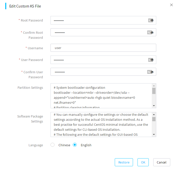
Parameters
· Root Password: Password of the administrator.
· Username: Username of a new user to be created.
· User Password: Password of the user.
· Partition Settings: Partition settings for OS installation.
· Software Package Settings: Settings of the software package used for OS installation.
· Language: Language of the OS to be installed. Options include Chinese and English.
View the default KS file
1. In the navigation pane, select Menu > Tools > PXE Deployment.
2. Click Configure Parameters.
3. Select an image, click Configure KS File in the Actions column of the image, and then select View Default KS.
You can view the settings in the default KS file on the page that opens.
Figure 192 Viewing the default KS file
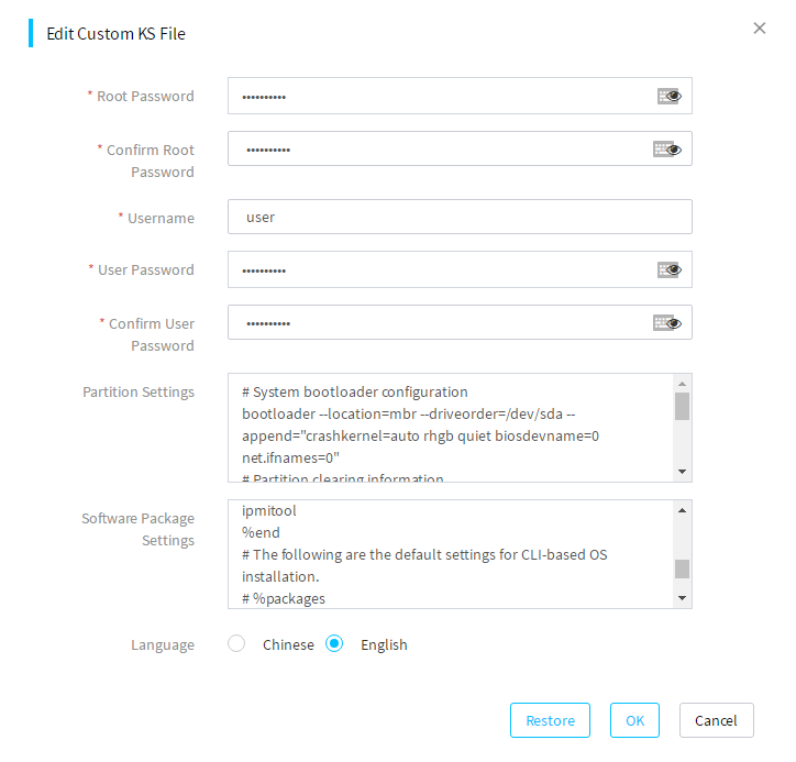
Apply a KS file
1. In the navigation pane, select Menu > Tools > PXE Deployment.
2. Click Configure Parameters.
3. Select an image, and click KS File in the Actions column of the image.
4. Select a KS file. Options include default and custom. PXE will use the settings in the specified KS file to install the OS for servers.
Figure 193 Applying a KS file
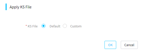
Push and install software
About this task
This module allows you to remotely install FIST SMS or general software to the OSs of the servers managed by FIST.
FIST System Management Service (FIST SMS) is the software installed in the OS of the managed servers to enhance the HDM and FIST management. After FIST SMS is successfully installed in the OS of a server, FIST SMS will run automatically and FIST will add this server as a FIST SMS device.
General software refers to any software you want to install in FIST. This feature pushes the software installation package and install script to the OS of a server and installs the software by executing the install script.
Restrictions and guidelines
The FIST SMS installation feature is available in FIST 2.00.16 and later versions.
The general software installation feature is available in FIST 2.00.33 and later.
This feature supports only FIST SMS-1.03.08 and later versions.
To avoid FIST SMS installation failure, do not make any changes to the installation package.
If the firewall feature is enabled on a server, the system automatically performs the following tasks after installing FIST SMS on the server:
· Adds the ports used by FIST SMS (ports 12580 and 6900) to the allowlist of the firewall. The ports will remain on the allowlist even after the FIST SMS server reboots.
· Enables the ICMPv4-In rule in the firewall settings so the FIST SMS server can be managed by FIST.
Prerequisites
To install FIST SMS, follow these guidelines:
· Install OpenJDK 1.8 (64-bit) on the server to be installed with FIST SMS. As from FIST SMS-1.37, if you install FIST SMS to a Window operating system, you do not need to configure the OpenJDK software in advance.
· To start FIST SMS successfully, use port 12580 only for FIST SMS.
· Verify that the winrm service is correctly configured on a Windows server or the sshd service has started on a Linux server.
To install general software, follow these guidelines:
· Prepare the software installation package and install script in advance and package them together into an installation file in the .tar.gz format.
· You might fail to install general software because of the following reasons:
¡ The running time of the install script exceeds the upper limit. The running time upper limit of the install script is 20 seconds in the Windows system and 20 minutes in the Linux system.
¡ The install script contains interactive statements, such as the pause statement.
· The extension of the install script varies by OS type.
¡ In the Windows operating system, the install script must be named as install.bat.
¡ In the Linux operating system, the install script must be named as install.sh.
· Verify that the winrm service is correctly configured on a Windows server or the sshd service has started on a Linux server.
Verify the winrm service status on a Windows server
1. Log in to the Windows system as an administrator and start PowerShell.
2. Execute the Get-Service winrm command to check the status of the winrm service.
¡ No actions are required if the service status is Running.
¡ Proceed to the next step if the service status is Stopped.
Figure 194 Checking the winrm service status
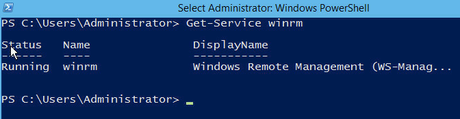
3. Execute the winrm quickconfig command to start the winrm service.
Figure 195 Starting the winrm service
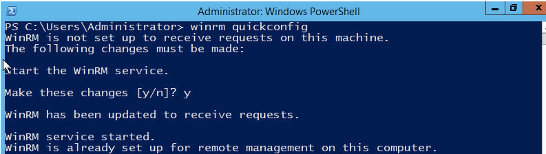
4. Execute the winrm set winrm/config/service '@{AllowUnencrypted="true"}' command to allow unencrypted transmission.
Figure 196 Allowing unencrypted transmission
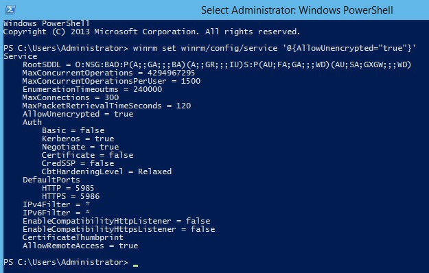
5. Execute the winrm set winrm/config/winrs '@{MaxMemoryPerShellMB="memory-size"}' command to set the maximum PowerShell memory size to a value greater than 1/16 of the server's physical memory.
Figure 197 Setting the maximum PowerShell memory
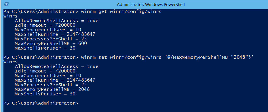
Verify the sshd service status on a Linux server
1. Log in to the Linux system as an administrator.
2. Install the sshd service and execute the service sshd start command to start the service. If the service has been installed, execute the service sshd status command to check the sshd service status.
¡ No actions are required if the service status is active.
¡ Proceed to the next step if the service status is inactive.
Figure 198 Checking the sshd service status
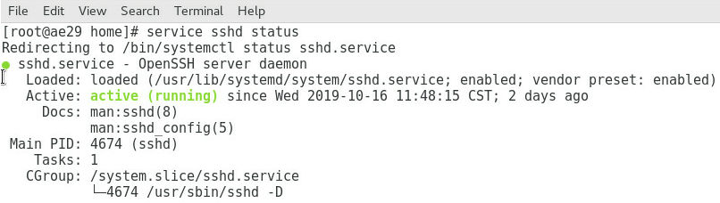
3. Execute the service sshd start command to start the sshd service. If the system prompts that sshd is not installed.
Procedure
1. In the navigation pane, select Menu > Tools > Push and Install Software.
2. Select an installation file type.
3. To upload a device list, perform the following steps:
a. (Optional.) Click Download Template under Device List File to download the device list template, and edit the devices in the device list template.
b. Click … in the Device List File field.
c. In the dialog box that opens, click Browse, select a device list file, and then click OK.
d. Click Upload. The Device List area displays the list of devices to which you can install FIST SMS or general software.
Figure 199 Installing FIST SMS
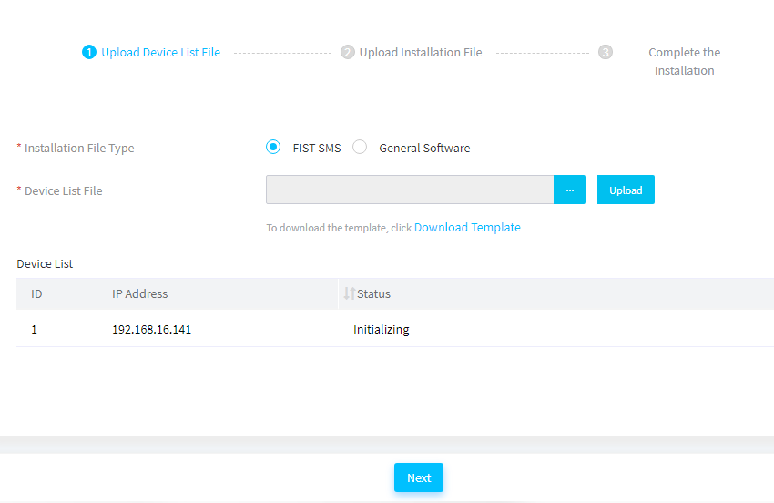
4. Click Next.
5. To upload a FIST SMS or general software installation file or FIST SMS driver file, perform the following tasks:
a. Click … in the FIST SMS Installation File, General Software Installation File, or FIST SMS Driver File field.
b. In the dialogue box that opens, click Browse, select the target file, and then click OK.
c. Click Upload. The system displays the name of the uploaded file.
Figure 200 Uploading the installation file
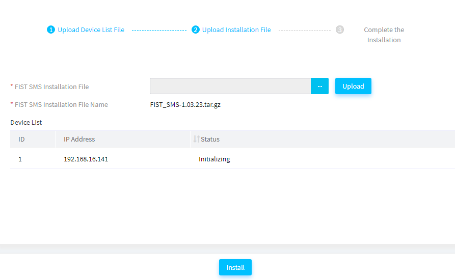
6. Click Install. The system starts to install FIST SMS or general software on the servers in the device list. It will take a long time, please wait for the process to finish.
After you install general software successfully, you can view the information in the Logs column. To view detailed logs, you can select devices in the device list and then click Download.
7. Click Finish.
Incorporate FIST to vCenter Server as a FIST plugin
About this feature
You can incorporate FIST as a plugin to vCenter Server. After that, you can access FIST through vSphere Client, an application that allows you to connect directly to a vCenter Server instance.
Prerequisites
Obtain the IP address, login username, and password of the vCenter Server.
Restrictions and guidelines
· If you use Google Chrome 85 or a later version, enter chrome://flags/#same-site-by-default-cookies in the address bar to disable the SameSite by default cookies feature, as shown in Figure 201. If you got stuck in the FIST login process by using another browser, try editing the browser cache settings in a similar way.
Figure 201 Editing the browser cache settings
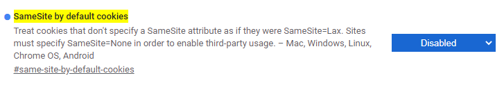
· After FIST registration is complete, if you need to register FIST of an earlier version or the same version again, uninstall the registered FIST plugin first. If you register FIST directly without uninstalling the previously registered FIST plugin, vCenter Server will not deploy the newly registered FIST plugin.
· To uninstall the deployed FIST plugin, use the vSphere Client SDK provided by vCenter Server (access the page at https://www.vmware.com/support/developer/webclient/index.html for more information). Use the extension-registration tool for the uninstallation.
¡ Command for uninstalling the FIST plugin:
$tools/extension-registration.bat -action unregisterPlugin -k sample.plugin -url https://vc-svr.example.com/sdk -u [email protected] -p secret
¡ Command parameter descriptions:
- -action: Specify the action to execute, which is unregisterPlugin in this example.
- -k sample.plugin: Specify the identifier of the target plugin, which is com.h3c.fist.localui in this example.
- -url https://vc-svr.example.com/sdk: Specify the URL of the SDK resources provided by vCenter Server, for example, https://192.168.128.117/sdk.
- -u [email protected]: Specify the login username of vCenter Server.
- -p secret: Specify the login password of vCenter Server.
¡ Command example for uninstalling FIST plugin:
D:\vsphere-client-sdk-6.7.0.40000-14186396\html-client-sdk\tools\vCenter plugin registration\prebuilt>extension-registration.bat -action unregisterPlugin -k com.h3c.fist.localui -u [email protected] -p ***** -url https:// 192.168.128.117/sdk
Procedure
1. Enter https://FIST ip address:https port in the address bar to log in to FIST. Then, enter https://FIST ip address:https port/server/0/register-plugin in the address bar to access the Register Plugin page, as shown in Figure 202.
|
|
IMPORTANT: To ensure normal access to FIST after FIST plugin registration, log in to FIST through HTTPS. |
Figure 202 Register Plugin page
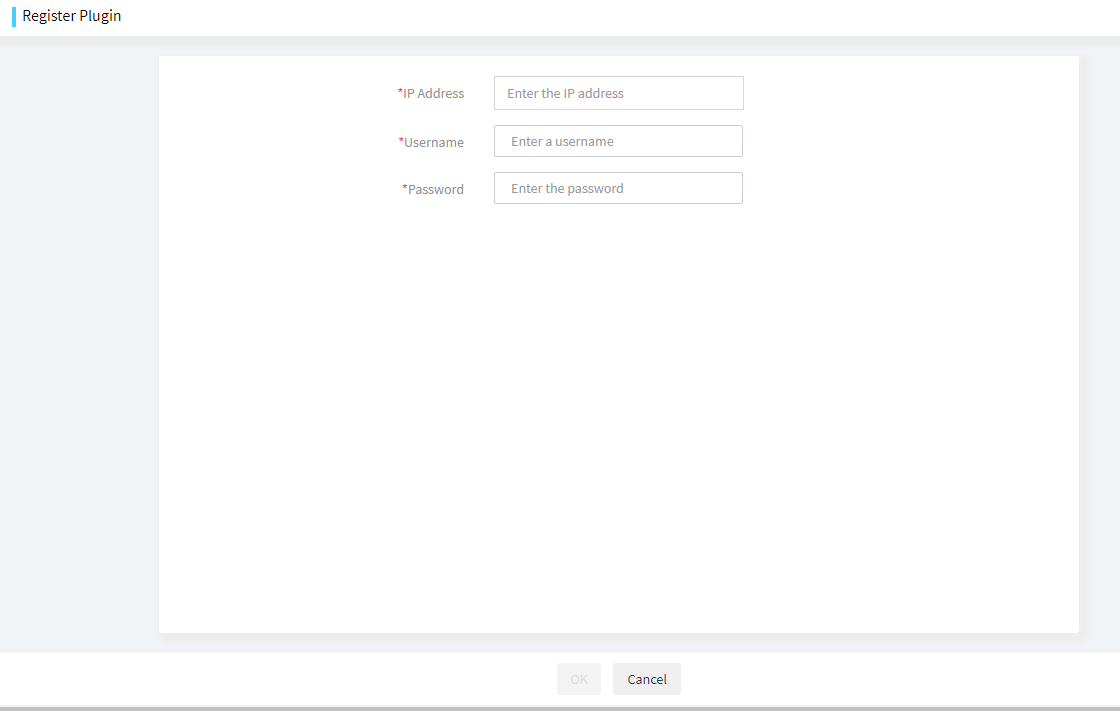
2. Enter the IP address, username, and password of the vCenter Server, and then click OK.
3. After the registration is complete, log in to vSphere Client. Click the FIST icon on the Shortcuts page to access FIST through vSphere Client, as shown in Figure 203.
Figure 203 vSphere Client interface
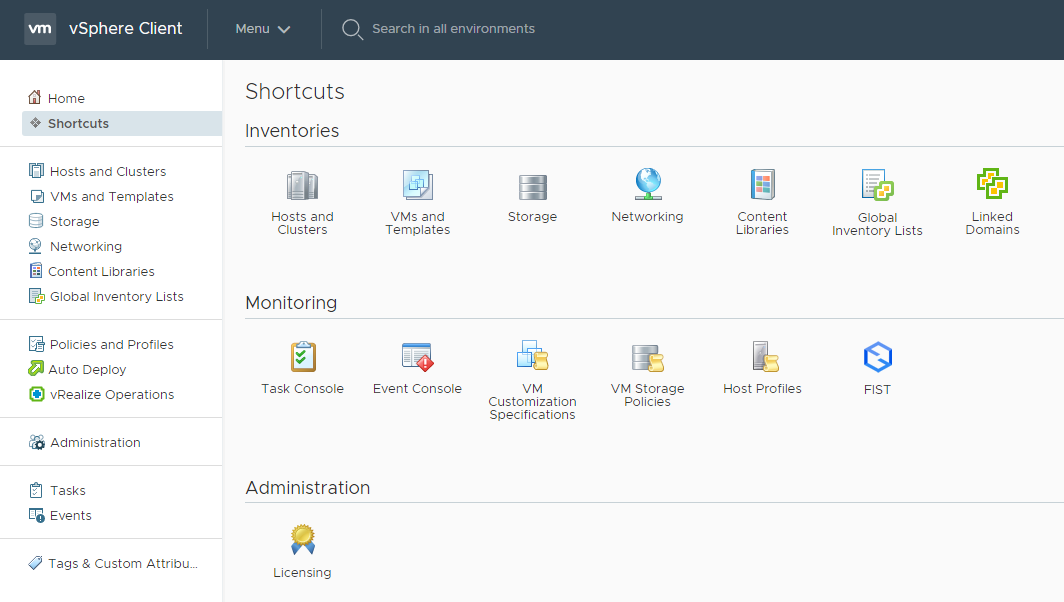
Configure the system settings
Configure the network settings
This module is available only when FIST runs on an AE module or VM.
This module allows you to view basic Ethernet adapter module information and routing entries, manage the IP address of the network ports, and test the network connectivity.
As shown in Figure 204, the AE module has a GE Ethernet adapter and a 10-GE Ethernet adapter. Two GE interfaces of the GE Ethernet adapter connect to OM module 1 and OM module 2, respectively. Two 10-GE interfaces of the 10-GE Ethernet adapters connect to interconnect module 1 and interconnect module 4, respectively.
Figure 204 Connections between modules in a server enclosure
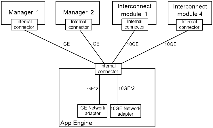
View basic Ethernet adapter information
Perform this task to view the basic information of the Ethernet adapter modules on the FIST server.
If the FIST server runs on an AE module, the following network ports are available:
· vmng—Aggregate interface of which the member ports are the network ports of the OM modules. The network port belongs to VLAN 1.
· vmng.om—Virtual network port used to communicate with an OM module. The virtual network port belongs to 4094.
· enp5s0f0—Network port connected to interconnect module 1.
· enp5s0f1—Network port connected to interconnect module 4.
Procedure
1. In the navigation pane, select Menu > System > Network.
2. View basic information of the Ethernet adapter modules. For more information about the parameters, see FIST Online Help.
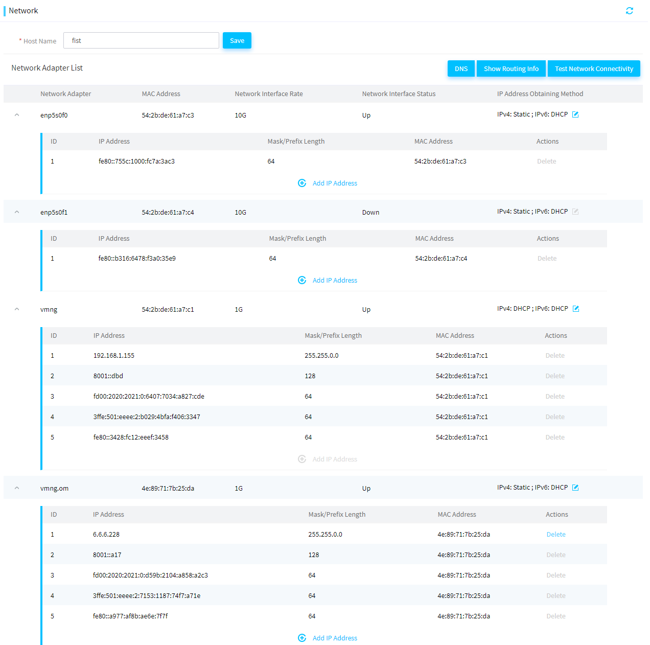
Set the host name for FIST
Perform this task to view or set the host name used for the FIST server. This feature is available only when the FIST server runs on an AE module.
Procedure
1. In the navigation pane, select Menu > System > Network.
2. Enter the host name.
3. Click Save.
Set the IP address obtaining method for a network port
Perform this task to set the method used to obtain an IP address for a network port of the FIST server. Supported method include static and DHCP.
Restrictions and guidelines
If you set the IP address obtaining method to DHCP for a network port, the network port will no longer use the static IP address. If you restore the method to static, the network port will use the previously specified static IP address.
Procedure
1. In the navigation pane, select Menu > System > Network.
2. Click the ![]() button
of a network port. In the dialog box that opens, set the IP address obtaining
method, and then click OK.
button
of a network port. In the dialog box that opens, set the IP address obtaining
method, and then click OK.
3. (Optional.) If you select the static mode, you must manually specify an IP address for the network port. For more information, see "Manage the IP addresses of a network port."
4. (Optional.) If you select the DHCP mode, the network port will send a DHCP request to apply for an IP address.
¡ If
the DHCP server assigns an IP address to the network port, click the ![]() icon in the top right corner to display
the obtained IP address.
icon in the top right corner to display
the obtained IP address.
¡ If the communication with the DHCP server fails in IPv4 DHCP mode, the system automatically restores the static method 1 minute later.
Manage the IP addresses of a network port
A network port can have multiple IP addresses for the port to communicate with devices on different subnets. For example, if the AE module needs to communicate with a server enclosure through an OM module, you must make sure that the network port connected to the OM module is on the same subnet as the server enclosure. To ensure this, perform this task to assign an IP address to the network port.
Assign an IP address to a network port
1. In the navigation pane, select Menu > System > Network.
2. Click Add New IP of a network port.
3. In the dialog box that opens, select IPv4 or IPv6, and enter an IP address and subnet mask or prefix length.
|
|
NOTE: When adding an IPv6 address, you cannot add an IPv6 address embedded with an IPv4 address (for example, ::192.168.0.1 ) or an IPv6 address that can be abbreviated into an address seemingly embedded with an IPv4 address (for example, ::c3:3). |
4. Click OK.
Delete an IP address of a network port
1. In the navigation pane, select Menu > System > Network.
2. Click Delete in the Actions column for an IP address of a network port. You cannot edit or delete a link-local address.
3. Click OK.
Configure DNS
About this task
This feature is available in FIST 2.34 and later.
Perform this task to configure DNS servers. You can configure IPv4 and IPv6 DNS servers simultaneously. To access websites or servers on the Internet through domain names, you must configure DNS for address resolution. Access to Internet is required for some features of FIST. To use such features, configure DNS as required.
This feature is available only when FIST runs on an AE module or a VM.
Restrictions and guidelines
FIST supports only static configuration of DNS server addresses. You cannot obtain DNS server addresses through dynamic acquisition.
Procedure
1. In the navigation pane, select Menu > System > Network.
2. Click DNS.
Figure 206 Configuring DNS
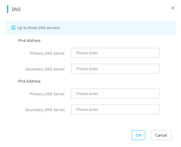
3. In the dialog box that opens, configure DNS servers. First configure the primary DNS servers.
4. Click OK.
5. (Optional.) To delete the existing DNS settings, delete DNS server information and click Save.
Test the network connectivity
Perform this task to test the network connectivity between the FIST server and an IP address and view the routing entries of the FIST server.
Procedure
1. In the navigation pane, select Menu > System > Network.
2. Click Ping IP Address and enter an IP address.
3. Click Ping. View the returned ping result.
4. (Optional.) Click Show Routing Info to view the routing information.
Configuring proxy settings
About this task
This feature is available in FIST 2.34 and later.
This module allows you to configure a proxy server. Thus, FIST can use the HTTP or HTTPS protocol for external communication.
In the current software version, FIST can use the proxy server only for the following features:
· Configure HTTP path as a repository path.
· Configure WeCom notification, SMS notification, or voice notification.
By default, no proxy is used when you use other features except for the above features in FIST.
Procedure
1. In the navigation pane, select Menu > System > Proxy Settings.
Figure 207 Configuring proxy settings
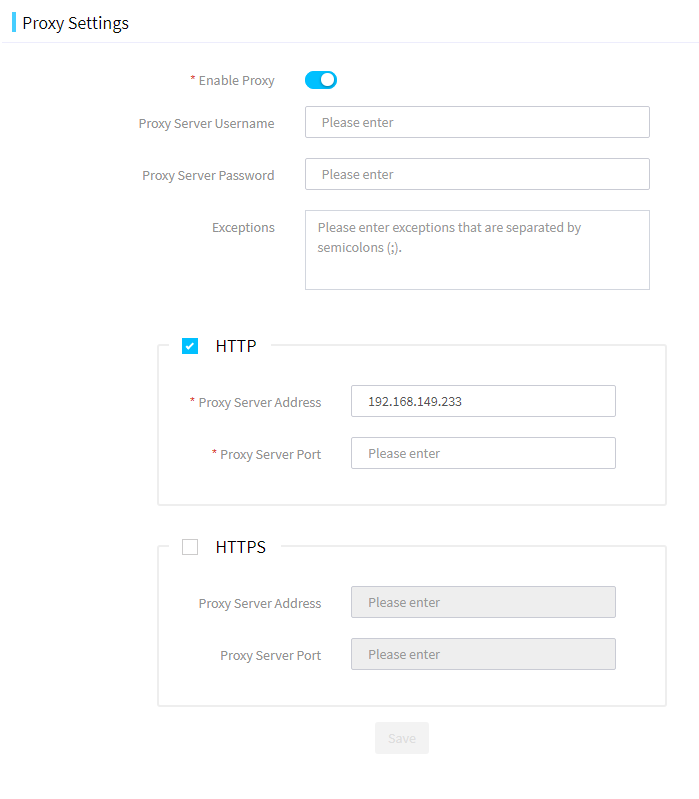
2. Select whether to enable proxy.
3. Enter the proxy server parameters.
4. (Optional.) Select HTTP to enable HTTP proxy.
5. (Optional.) Select HTTPS to enable HTTPS proxy.
6. Click Save.
Configure the system time
About this task
This feature is available in FIST 2.00.17 and later.
This module allows you to view or set the system time of FIST. This feature is available only when FIST runs on an AE module or a VM.
You can configure FIST to synchronize the system time with the NTP server or manually set the system time.
Synchronize the system time with an NTP server
1. In the navigation pane, select Menu > System > System Time.
2. Select Sync with NTP Server.
3. Enable the Auto Sync option.
4. Enter the IP addresses of the primary NTP server and the secondary NTP server.
Figure 208 Configuring the system time settings
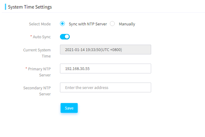
5. Click Save.
Manually set the system time
1. In the navigation pane, select Menu > System > System Time.
2. Select Manually, and select the date and time to be used by FIST.
Figure 209 Setting the system manually
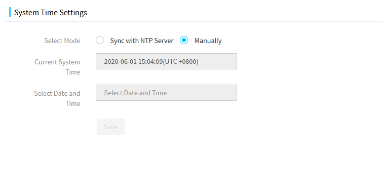
3. Click Save.
Configure a cluster
About this task
This feature is available in FIST 2.00.17 and later.
This module allows you to create or manage a cluster of AE modules to implement high availability. FIST automatically monitors the status of the primary node. When the primary node fails, FIST will switch to run on the secondary node, which avoids service interruption caused by the failure of the primary AE module.
Prerequisites
Cluster creation requires data synchronization. For correct data synchronization, make sure the time difference between the primary and secondary nodes is shorter than 10 seconds. For more information about how to set the system time, see "Configure the system time."
If a cluster is created, make sure the following conditions are met:
· Make sure the primary and secondary nodes can reach each other. As a best practice, assign static IP addresses to ports for the primary and secondary nodes to communicate with each other and make sure the ports have the same subnet mask.
· Make sure the primary and secondary nodes each have a unique host name for FIST access. Do not set the host name to localhost or a string of all digits.
· Do not configure multiple IP addresses on the same subnet for each network port.
For more information about how to set the host name and the network settings, see "Configure the network settings."
Restrictions and guidelines
· The secondary FIST node in the cluster will be stopped during cluster creation.
· During cluster creation, do not power off the AE modules or disconnect the network. Data synchronization will take a long time, please wait till the whole progress finishes.
· During cluster creation, do not perform any other operations on FIST of the primary node.
· After the cluster is created, do not edit the host name, network, or system settings of FIST.
· FIST cannot be reverted from cluster mode to standalone mode.
· The host name of an AE module used in a cluster cannot be localhost or all digits.
· As a best practice, use a static IP address for the port on the primary and secondary node used for communication.
· Cluster creation failure will cause the unavailability of FIST. Please try again to create the cluster.
Procedure
1. In the navigation pane, select Menu > System > Cluster
2. Click the Create Cluster link.
3. On the page that opens, configure the following parameters of the cluster to be created.
¡ Secondary Node Address—IP address used by the secondary node to communicate with the primary node. As a best practice, use the IP address of network port vmng.om or the 10-GE network port of the secondary AE module.
¡ FIST Virtual IP Address—Virtual IP address for users to access FIST after the cluster is created.
¡ iSCSI Virtual IP Address—IP address used to configure the iSCSI service. Make sure the entered iSCSI virtual IP address is on the same network segment as an IP address of the 10-GE network port on the primary AE module.
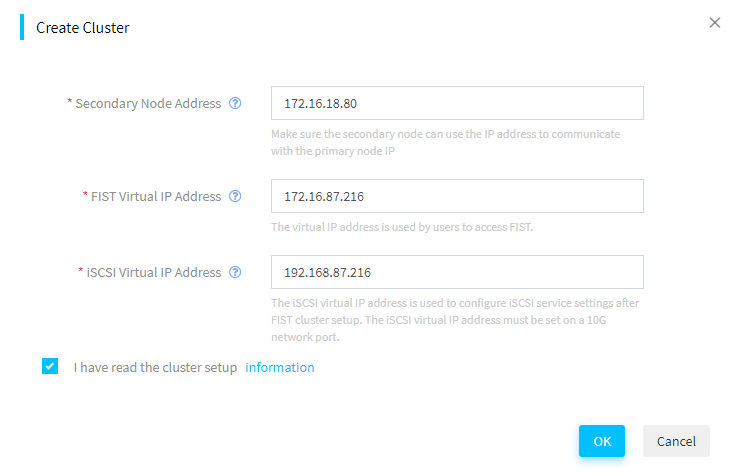
4. Click OK. You can see the progress of the creation from the progress bar. To view detailed information about the cluster creation, click View Log.
5. FIST will automatically restart after the cluster is successfully created. Log in to FIST by using the virtual IP address of FIST.
6. View information about the primary and secondary nodes on the Cluster page.
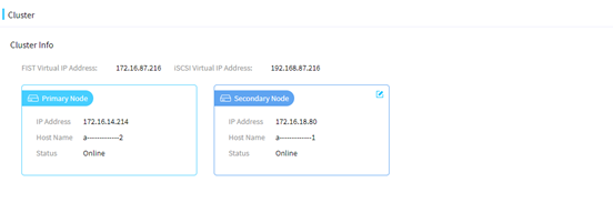
7. Click the Edit icon ![]() next
to the secondary node. In the dialog box that opens, enter the IP address of
the node to replace the current secondary node. Then, click OK. You can see the progress of the replacement from the
progress bar.
next
to the secondary node. In the dialog box that opens, enter the IP address of
the node to replace the current secondary node. Then, click OK. You can see the progress of the replacement from the
progress bar.
Maintain and upgrade
Perform this task to back up and restore the FIST data and upgrade the FIST software.
Back up and restore FIST data
About this task
This feature is available in FIST 2.00.14 and later.
This module allows you to back up and restore the FIST data, download system operation logs, and restore the default FIST settings.
The FIST data that can be backed up or restored includes the device information, component update task information, configuration template or file information, address pool information, and user information. Repositories, image files uploaded to the image list, cloned images, diskless boot volumes, and listening settings cannot be backed up.
After you restore the default settings, the information that can be backed up on the FIST server is cleared and the user settings are restored to the default.
Restrictions and guidelines
· Before you restore the FIST data or restore the default settings of FIST, back up the current FIST data.
· To avoid restoration failure, do not perform any operations that might affect the restoration during FIST data restoration or default FIST setting restoration.
· To ensure that FIST operates properly, you must manually reboot FIST after you restore the FIST data or restore the default settings of FIST. In FIST-2.39 and later, after FIST data restoration or default FIST setting restoration, FIST of the package version will be automatically stopped, and FIST on a VM or AE module will be restarted.
· To avoid configuration file verification failure during data restoration, do not make any changes to the backup configuration file.
· A server template or server configuration file becomes invalid after backup or restoration if it contains an image file or repository in the system settings. You must reconfigure the template or file before applying it to a server.
Procedure
1. In the navigation pane, select Menu > System Maintain and Upgrade. Click the Backup and Restore tab.
Figure 212 Backup & Restore page
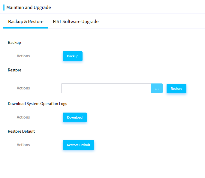
2. To back up the running configuration, click Backup. The system will export the running configuration to a compressed file.
3. To restore the configuration in a configuration file, click … next to Restore, select the target configuration file, and then click Restore.
Figure 213 Restoring the configuration in a configuration file
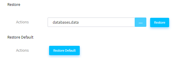
4. To download FIST system operation logs in a compressed file to the local host, click Download.
5. To restore the default settings, click Restore Default. In the dialog box that opens, click OK.
Upgrade FIST software
About this task
This feature is available in FIST-2.39 and later.
This feature allows you to upgrade or downgrade the FIST software version. FIST software upgrade will not cause FIST data loss. However, as a best practice, back up the critical data before upgrading FIST.
The FIST upgrade interface is available only for FIST running on a VM or AE module. FIST of the package version does not need installation. To upgrade FIST of the package version, replace the new package with the old package.
Restrictions and guidelines
· To ensure that FIST can be upgraded normally, first stop the other FIST operations in progress before upgrading FIST.
· Upgrading FIST will log out all logged-in users except the current user. Additionally, other users cannot log in during the FIST upgrade process.
· Upgrading FIST will interrupt or restart related processes in the system where FIST is installed. If these processes are being used, related services might be interrupted.
Procedure (for FIST on a VM or AE module)
1. In the navigation pane, select Menu > System > Maintain and Upgrade. Click the FIST Software Upgrade tab.
Figure 214 FIST Software Upgrade page
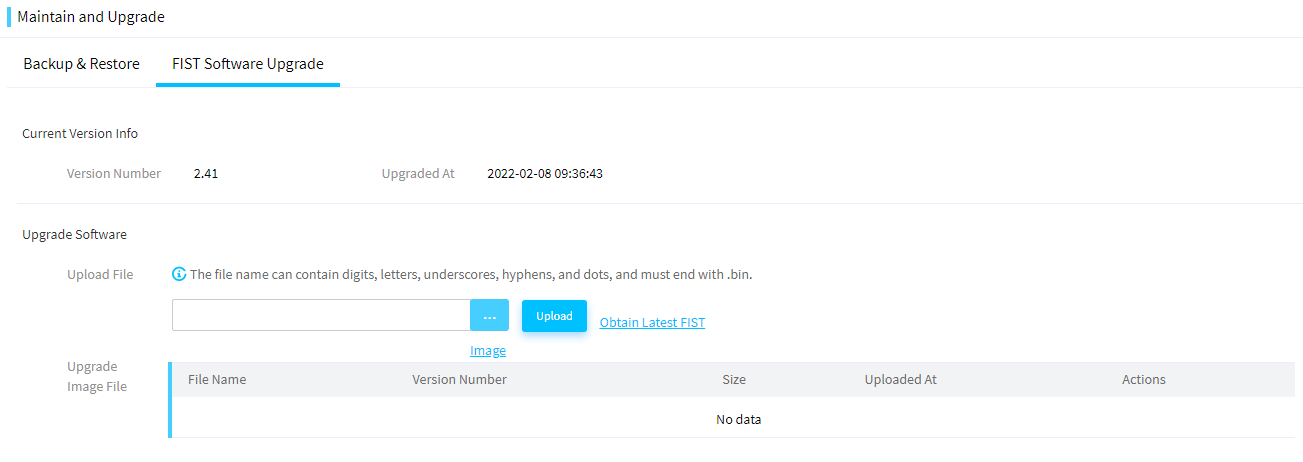
2. (Optional.) Click Obtain Latest FIST Image to download the needed FIST software upgrade package from the official website.
3. Click the … button for the software upgrade operation, select the FIST upgrade package, and click Upload to upload the upgrade package.
4. Click Start Upgrade. In the dialog box that opens, click OK to start upgrading FIST.
After the upgrade is finished, FIST will automatically restart and return to the login page. After FIST is restarted, refresh the page, and log in to use the new FIST version.
Procedure (for FIST of the package version)
|
|
IMPORTANT: After the upgrade, the port configuration cannot be retained. |
1. Obtain the FIST upgrade package from the official website, and then click STOP to stop FIST, as shown in Figure 215.
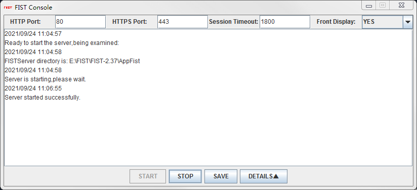
2. Select the new FIST upgrade package, decompress the package, and override the original FIST directory. Then, choose to replace all files as instructed, as shown in Figure 216.
Figure 216 Replacing all files
3. Restart FIST.
Configure the security tip for login
About this task
This feature is available in FIST 2.34 and later.
This module allows you to enable and configure the security tip for login.
Procedure
1. In the navigation pane, select Menu > System > Security Tip for Login.
Figure 217 Configuring the security tip for login
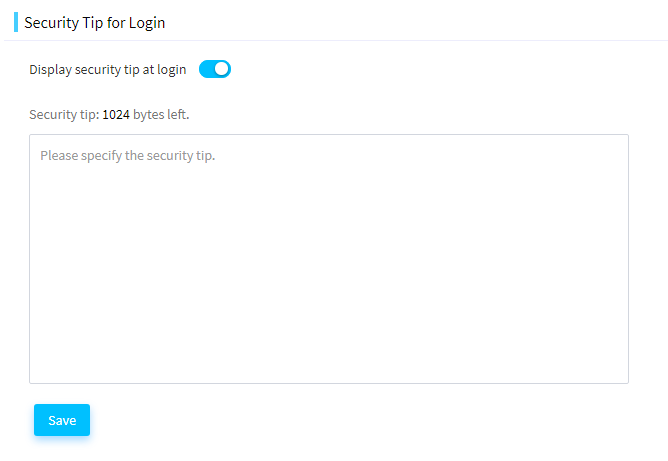
2. Select to enable Display security tip at login.
3. Enter a security tip or leave the security tip field empty.
4. Click Save.
After you save the security tip successfully, you can view the configured security tip on the login page.
Manage LDAP
FIST can work with an LDAP server to provide quick access to LDAP users on the server.
You can add LDAP servers to FIST and then add LDAP user groups on the LDAP servers to FIST. Member users in the LDAP user groups can then log in to FIST directly with their credentials stored in the LDAP server.
View LDAP server information and test connectivity to a server
1. In the navigation pane, select Menu > System > LDAP Management.
The LDAP Settings tab displays information about the LDAP servers configured in the system, each on a separate card.
Figure 218 LDAP settings tab
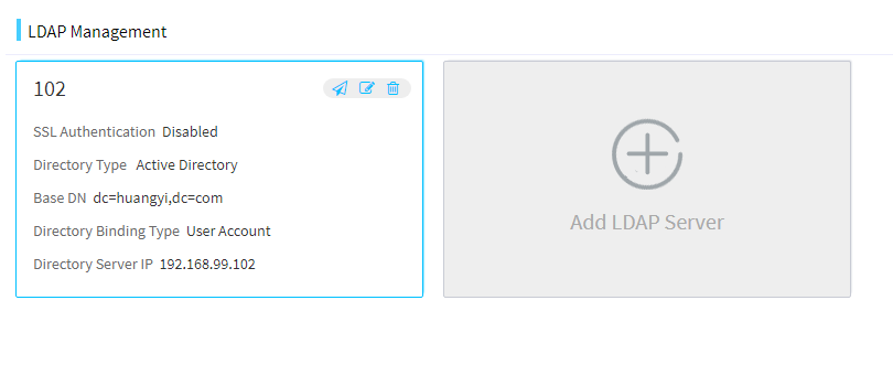
2. (Optional.) To test
connectivity to an LDAP server, click the ![]() icon in the top
right corner of the LDAP server card. For an LDAP server that uses the User Account directory binding type, you will be prompted
to enter the username and password for connectivity test.
icon in the top
right corner of the LDAP server card. For an LDAP server that uses the User Account directory binding type, you will be prompted
to enter the username and password for connectivity test.
Add an LDAP server
Perform this task to add an LDAP server to FIST. FIST supports a maximum of five LDAP servers.
Procedure
1. In the navigation pane, select Menu > System > LDAP Management.
2. Click Add LDAP Server.
3. In the Add LDAP Server dialog box that opens, configure the LDAP server parameters.
Figure 219 Add LDAP server dialog box
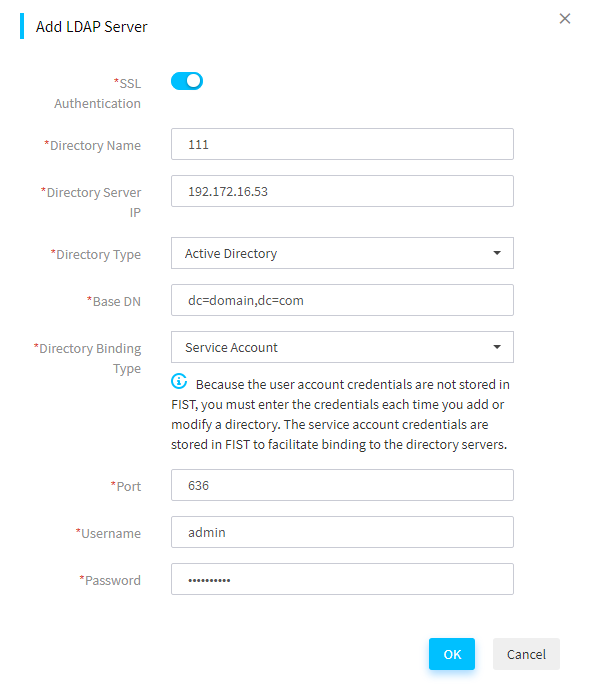
4. Click OK.
Edit an LDAP server
1. In the navigation pane, select Menu > System > LDAP Management.
2. Click the Edit
icon ![]() in the Actions column for the target
LDAP server.
in the Actions column for the target
LDAP server.
3. In the Edit LDAP Server dialog box that opens, edit the LDAP server parameters and click OK.
Delete an LDAP server
1. In the navigation pane, select Menu > System > LDAP Management.
2. Click the Delete
icon ![]() in the Actions column for the target
LDAP server.
in the Actions column for the target
LDAP server.
3. In the confirmation dialog box that opens, click OK.
Acronyms
|
Term |
Definition |
|
BIOS |
Basic Input Output System |
|
CPLD |
Complex Programmable Logic Device |
|
CPU |
Central Processing Unit |
|
DHCP |
Dynamic Host Configuration Protocol |
|
FIST |
Fast Intelligent Scalable Toolkit |
|
FIST SMS |
FIST System Management Service |
|
GUI |
Graphical User Interface |
|
HBA |
Host Bus Adapter |
|
HDM |
Hardware Device Management |
|
IPMI |
Intelligent Platform Management Interface |
|
OS |
Operating System |
|
PXE |
Preboot Execute Environment |
|
RAID |
Redundant Arrays of Independent Disks |
|
SDS |
|
|
UEFI |
Unified Extensible Firmware Interface |
