- Table of Contents
- Related Documents
-
| Title | Size | Download |
|---|---|---|
| 01-Text | 2.26 MB |
3SFF drive backplane (1SAS/SATA+2UniBay)
B/D/F information about the server
Component installation guidelines
Storage controller and its power fail safeguard module
Installing or removing the blade server
Connecting the blade server to a network
Connecting through the management module
Verifying the blade server status
Modifying the default user password of OM
Modifying the default IP address of the OM module
Modifying the default user password of HDM
Modifying the default IP address of HDM
Logging into the blade server operating system
Configuring basic BIOS settings
Installing the operating system and hardware drivers
Replaceable parts and their videos
Replacing the riser card and PCIe card
Removing the riser card and PCIe card
Installing the riser card and PCIe card
Replacing the storage controller and its power fail safeguard module
Removing the storage controller and its power fail safeguard module
Installing a storage controller and a power fail safeguard module
Replacing the straight-through card
Removing the straight-through card
Installing the straight-through card
Replacing the standard PCIe NIC
Removing a mezzanine network adapter
Installing a mezzanine network adapter
Removing a SATA M.2 SSD module
Installing a SATA M.2 SSD module
Replacing a SATA M.2 SSD adapter
Removing a SATA M.2 SSD adapter
Installing a SATA M.2 SSD adapter
Replacing the NVMe VROC module
Installing the NVMe VROC module
Installing and setting up a TCM or TPM
Installing and setting up a TPM or TCM
Installation and setup flowchart
Enabling the TCM or TPM in the BIOS
Configuring encryption in the operating system
Logging in to the blade server operating system
Accessing the blade server HDM interface
Monitoring the temperature and humidity in the equipment room
Updating firmware for the server
Safety information
To avoid bodily injury or damage to the server, read the following information carefully before you operate the server. In practice, the safety information includes but is not limited to what are mentioned in this document.
General operating safety
· Only H3C-authorized personnel or professional engineers can run the device.
· Place the device on a clean, stable workbench or floor for servicing.
· Before running the server, make sure that all cables are correctly connected.
· To cool the server adequately, follow the guidelines below:
¡ Do not block the ventilation holes on the server.
¡ Filler panels must be installed in idle slots of the server, such as drive slots.
¡ Do not run the server if no chassis cover, air duct, or filler panel for idle slots is installed.
· Make sure that you move or place the server evenly and slowly.
· To avoid being burnt, allow the server and its internal modules to cool before touching them.
Electrical safety
To avoid bodily injury or damage to the server, follow these guidelines:
· Verify whether the operation area has potential risks carefully, such as an ungrounded chassis, unreliable grounding, or wet floor.
· Make sure that you disable the power supply before you perform actions in power-off state.
· Power off the server when installing or removing any components that are not hot swappable.
Battery safety
The server's system board contains a system battery, which is designed with a lifespan of 3 to 5 years.
If the BIOS no longer automatically displays the correct date and time, you might need to replace the battery. When you replace the battery, follow these safety guidelines:
· Do not attempt to recharge the battery.
· Do not expose the battery to a temperature higher than 60°C (140°F).
· Do not disassemble, crush, puncture, short external contacts, or dispose of the battery in fire or water.
· Dispose of the battery at a designated facility. Do not throw the battery away together with other wastes
ESD prevention
Preventing electrostatic discharge
To prevent electrostatic damage, follow these guidelines:
· Transport or store the server with the components in antistatic bags.
· Keep the electrostatic-sensitive components in separate antistatic bags until they arrive at an ESD-protected area.
· Place the components on a grounded surface before removing them from their antistatic bags.
· Avoid touching pins, leads, or circuitry.
· You must take ESD preventions before touching the electrostatic-sensitive components.
Grounding methods to prevent electrostatic discharge
The following are grounding methods that you can use to prevent electrostatic discharge:
· Wear an ESD wrist strap and make sure it makes good skin contact and is reliably grounded.
· Take adequate personal grounding measures, including wearing antistatic clothing and static dissipative shoes.
· Use conductive field service tools.
· Use a portable field service kit with a folding static-dissipating work mat.
About the Blade Server
|
|
NOTE: This manual is a general document for the product. For customized products, the specifications may vary. · In this manual, the model of all components are simplified (for example, the prefix or suffix is deleted). Memory model DDR4-3200-16G-2Rx8-R represents the following models: UN-DDR4-3200-16G-2Rx8-R, UN-DDR4-3200-16G-2Rx8-R-F, and UN-DDR4-3200-16G-2Rx8-R-S. Figures in this document are for illustration only. The actual product may vary. |
Product Overview
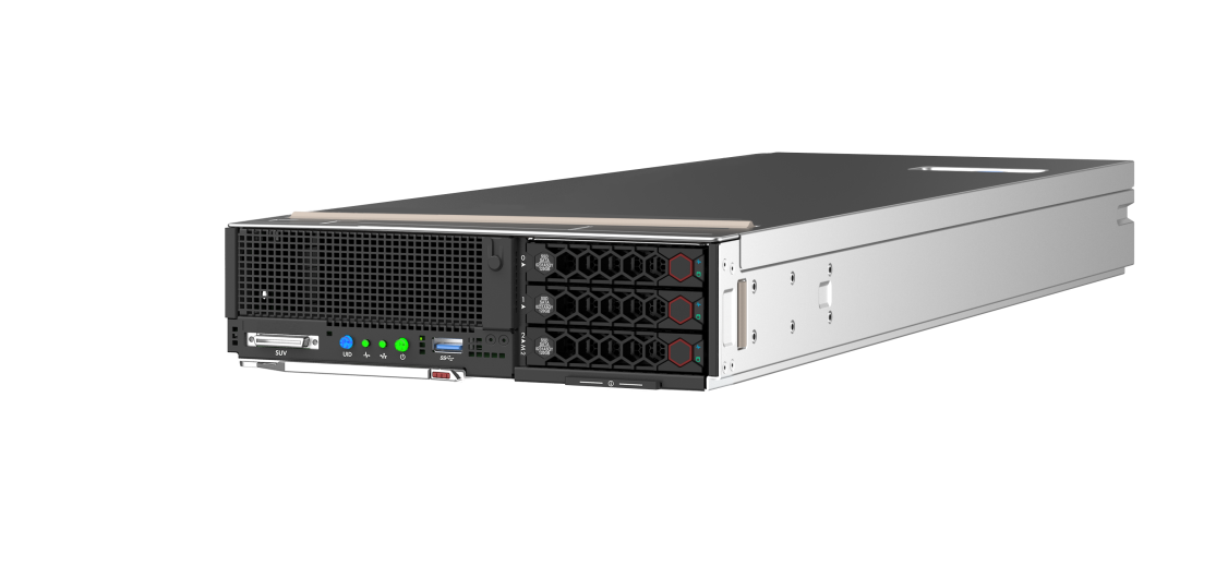
H3C UniServer B5700 G5 server (hereinafter referred to as the blade server) is an H3C-proprietary blade server with a maximum of two Intel Whitley Ice Lake series processors or Montage Jintide C3 series processors. The server provides strong computing performance and flexible expansion capability. The blade server can be installed in an H3C UniServer B16000 blade chassis (hereinafter referred to as the chassis) and managed through the OM module in a centralized way.
Figure 1 shows the appearance of the blade server.
Figure 1 Appearance of the blade server
Technical parameters
This section introduces the product specifications and technical parameters of the blade server.
Product specifications
Table 1 Product Specifications
|
Feature |
Description |
|
Processor |
Supports 2 Intel Whitley Ice Lake series processors or Montage Jintide C3 series processors l Up to 235 W power consumption per processor l Base frequency up to 3.1 GHz l Up to 48 MB cache per processor |
|
Memory |
Up to 32 memory modules, including DDR4 and PMem 200 memory module |
|
Storage controller |
· Embedded VROC array controller · High-performance storage controller · NVMe VROC module |
|
Chipset |
Intel C621A Lewisburg chipset |
|
Network interface |
2 × embedded 1 Gb/s Ethernet interfaces, connected to chassis backplane for interconnection with the active and standby OM modules |
|
The graphics card chip (model: AST2500) is integrated into the BMC chip. With 64 MB video memory, it supports maximum resolution of 1920 x 1080@60 Hz (32 bpp). Resolution description: · 1920 x 1080: Indicates that there are 1920 pixel columns horizontally and 1080 pixel columns vertically. · 60 Hz: Indicates the refresh rate of 60 times per second. · 32 bpp: Indicates the number of color bits. The larger the number of color bits, more colors will be displayed. |
|
|
I/O port |
· 1 × SUV connector (front panel, for SUV cable connection) · Supports up to 3 USB ports: ¡ 1 × USB 3.0 port (on the front panel) ¡ 2 × USB 2.0 ports (expanded by using the SUV cable) · 1 × VGA port (expanded by using the SUV cable) · 1 × serial port connector (expanded by using the SUV cable) |
|
Expansion slot |
Up to 5 PCIe 3.0 connectors (1 × memory controller connector, 1 × standard connector, 3 × Mezz card connectors) |
|
Certification |
CCC, CE, and FCC |
Technical parameters
Table 2 Technical parameters
|
Category |
Item |
Description |
|
Physical specifications |
Dimensions |
· Height × width: 59.5 × 215 × 613.4 mm · Height × width: Half height and half width · Maximum number of blade servers in a chassis: 16 |
|
Max. weight |
8.8 kg |
|
|
Power consumption |
Max. power |
710 W |
|
Environmental specifications |
Temperature |
Operating temperature: 5°C to 45°C NOTE: · The maximum operating temperature supported by the server may be reduced under some configurations. For details, see the "Operating temperature requirements". |
|
Storage temperature: –40°C to 70°C |
||
|
· Operating humidity: 8% to 90% (non-condensing) · Storage humidity: 5% to 95% (non-condensing) |
||
|
· Operating altitude: –60 m to +5000 m. When the altitude is higher than 900 m, the allowed maximum temperature decreases by 0.33°C for every 100 m increased in altitude (HDDs are not supported if the altitude is higher than 3000 m). · Storage altitude: –60 m to +5000 m |
Components
This sections describes components of the blade server.
Figure 2 Components of the blade server
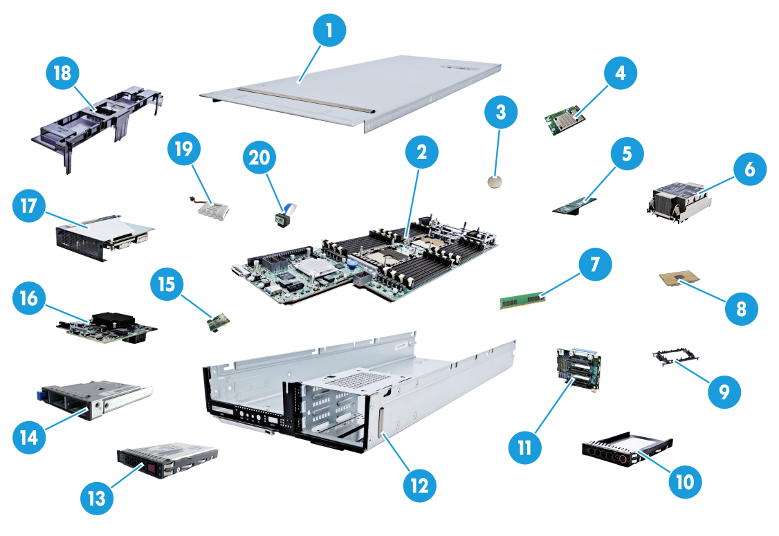
Table 3 Description of blade server components
|
Name |
Description |
|
|
1 |
Chassis cover |
- |
|
2 |
System board |
One of the most important parts of a blade server, on which multiple components are installed, such as a CPU, memory, and PCIe module. It is integrated with basic server components, including the BIOS chip, BMC chip, and PCIe connectors. |
|
3 |
System battery |
Powers the system clock to ensure a correct system date and time. |
|
4 |
Mezzanine module |
Refers to modules connected by the mezzanine connectors. Mezzanine modules communicate with the processor via the PCIe protocol. One of the mezzanine modules is the mezzanine NIC, which is used to connect to the interconnect module (ICM) at the rear of the chassis to enable interaction between the blade server and the client. |
|
5 |
Straight-through card |
Connects the embedded VROC array controller soft RAID and SATA drives. |
|
6 |
processor heatsink |
Cools the CPU. |
|
7 |
Memory |
Temporarily stores operational data in the CPU and data exchanged with external storage devices such as drives. |
|
8 |
Processor |
Integrates the memory controller and PCIe controller to provide powerful data processing capabilities for blade servers. |
|
9 |
Processor retaining bracket |
Attaches a CPU to the heatsink. |
|
10 |
Drive filler panel |
Ensures adequate cooling of the blade server. Install a filler panel when no drive is installed on the blade server. |
|
11 |
Drive backplane |
Powers the drive and provides a data transfer channel. |
|
12 |
Blade server chassis |
Centralizes blade server parts and components. |
|
13 |
Drive |
Provides data storage media for blade servers, and supports hot swapping. |
|
14 |
SATA M.2 SSD adapter module |
Expands two SATA M.2 SSD modules, and supports hot swapping. |
|
15 |
Encryption module (TCM/TPM module) |
Provides encryption services for servers to improve server data security. |
|
16 |
Storage controller |
Provides RAID support for SAS/SATA drives, and supports RAID expansion, RAID configuration memory, online upgrade and remote setup. |
|
17 |
Riser card |
Standard PCIe cards are installed to the blade server through the riser card. |
|
18 |
Air duct |
Provides cooling ducts inside the blade server. |
|
19 |
Supercapacitor |
Powers the Flash card integrated or installed on the memory controller in case of unexpected system power failure, to achieve power failure protection for data on the memory controller. |
|
20 |
NVMe VROC module |
Activates the NVMe drive array feature based on the VMD technology. |
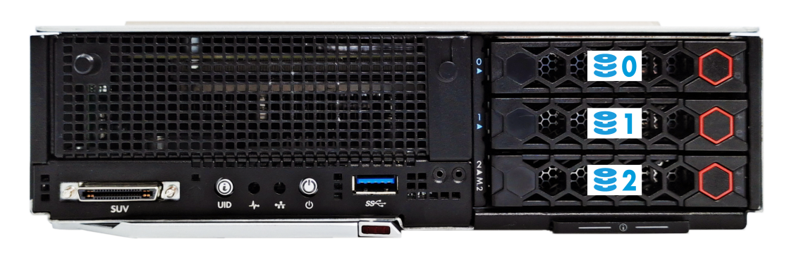
Front panel
This section introduces the components, LEDs, and interfaces on the front panel.
Front panel components
Figure 3 Front panel of the blade server
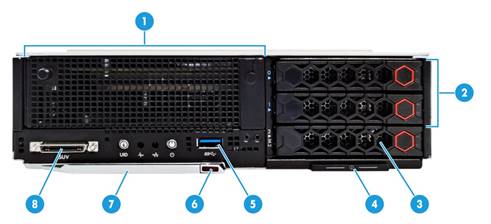
Table 4 Description of front panel components
|
Description |
|
|
1 |
· Optional riser card (for processor 2) |
|
2 |
Optional SAS/SATA drive or NVMe drive |
|
3 |
Optional SAS/SATA drive or SATA M.2 SSD module (via the adapter module) |
|
4 |
Pull-out asset label |
|
5 |
USB 3.0 port |
|
6 |
Buttons for releasing the locking levers |
|
7 |
Locking levers |
|
8 |
SUV connector |
|
· USB 3.0 ports can be used to connect the USB flash drive, USB keyboard or mouse, USB optical drive (for OS installation). |
|
LEDs and buttons
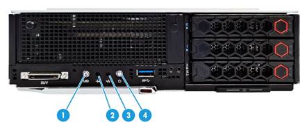
Figure 4 Front panel LEDs and buttons
|
SN |
Description |
Status |
|
1 |
UID button/LED |
· Steady blue—UID LED is activated. The UID LED can be activated by using the following methods: ¡ Press the UID button LED. ¡ Activate the UID LED from HDM or OM. · Flashing blue: ¡ 1 Hz—The upgrade is being upgraded or the system is being managed from HDM. Do not power off the server. ¡ 4 Hz—HDM is restarting. To restart HDM, press the UID button LED for ten seconds. · Off—UID LED is not activated. |
|
2 |
Health LED |
· Steady green—The system is operating correctly. · Flashing green (4 Hz)—HDM is initializing. · Flashing amber (0.5 Hz)—A predictive alarm is present. · Flashing amber (1 Hz)—A minor alarm is present. · Flashing red (1 Hz)—A critical alarm is present. |
|
3 |
Embedded GE network adapter LED |
· Steady green—A link is present on the port. · Flashing green—The port is receiving or sending data. · Off—No link is present on the port. |
|
4 |
Power on/standby button and system power LED |
· Steady green—The system has started. · Flashing green (1 Hz)—The system is starting. · Steady amber—The system is standby. · Off—No power is present. |
|
· When the Health LED shows that the system is faulty, check the system operating state on HDM. ¡ No power supplies are present. ¡ The installed power supplies are faulty. ¡ The chassis is not powered. |
||
SUV cable
The SUV cable connects to the SUV connector on the front panel of the blade server. The SUV cable allows for the expansion of two USB 2.0 ports, one serial port and one VGA port for the blade server.
Figure 5 SUV cable
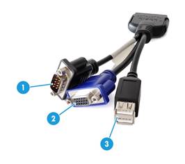
Table 6 SUV cable description
|
Item |
Description |
Application |
|
1 |
Serial port |
Diagnoses faults and debugs devices. |
|
2 |
VGA connector |
Connects terminal displays such as monitors or KVM devices |
|
3 |
2 × USB 2.0 connectors |
The extended USB 2.0 connectors and USB 3.0 connector that comes with the default configuration are all available for the following USB devices: · USB drives · USB keyboards or mouses. · USB optical drives for installing operating systems. |
Serial asset label pull tab
The serial label pull tab is on the front panel, as shown in "Front panel components." It provides the following information about the blade server:
· Product QR code. Users can scan the QR code to access the product document center, and view documents for the blade server.
· HDM default information.
· Product serial number.
· Server model.
System board
System board layout
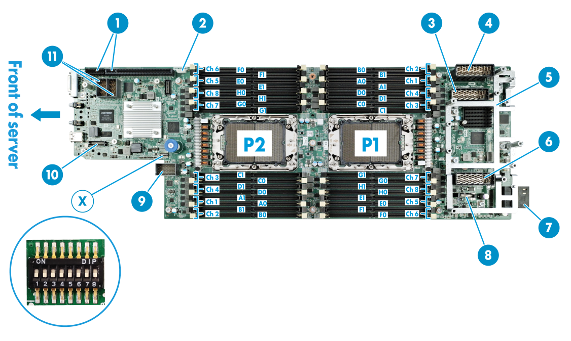
Table 7 Layout description
|
Description |
|
|
1 |
PCIe riser card connector (for CPU 2) |
|
2 |
NVMe VROC module connector |
|
3 |
Mezzanine module connector 2 (for processor 2, ICM 2/5) |
|
4 |
Mezzanine module connector 3 (slave processor 1, ICM 2/6) |
|
5 |
Mezzanine module supporting bracket |
|
6 |
Mezzanine module connector 1 (for processor 1, ICM 1/4) |
|
7 |
Backplane connector |
|
8 |
System battery |
|
9 |
Drive backplane connector |
|
10 |
TPM/TCM connector |
|
11 |
Storage controller connector |
|
X |
System maintenance switch |
DIMM slots
The DIMM slot layout is shown in Figure 7. A0, B0 ......H0, H1 indicate the DIMM slot number. See "DIMMs" for specific installation guidelines for DIMMs.

System maintenance switch
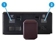
The system maintenance switch has 8 pins, as shown in Figure 8.
Figure 8 System maintenance switch
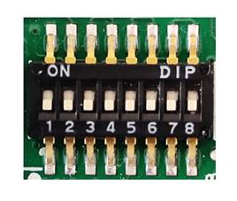
The following problems can be solved with the system maintenance switch. Table 8 describes meanings of the system maintenance switch and "System board layout" shows the layout.
· Users forget the HDM login user name or password and cannot log in to HDM.
· Users forget the BIOS password and cannot enter BIOS.
· Default BIOS settings should be restored.
Table 8 System maintenance switch description
|
Position |
Description (default value: Off) |
Remarks |
|
|
1 |
l Off—HDM login requires the username and password of a valid HDM user account. l On—HDM login requires the default username and password. |
When pin 1 is On, users can permanently log in to HDM with the default username and default password. It is recommended that change pin 1 to Off after completing the operation. |
|
|
5 |
l Off—Normal server startup. l On—Restores the default BIOS settings. |
When the server is powered off, change pin 5 to On, then to Off again, and finally start the server. The default BIOS settings will be restored.
When pin 5 is changed to On, the server cannot be started. Therefore, stop the running service in advance and make sure the server is powered off. Otherwise it may cause business data loss. |
|
|
6 |
l Off—Normal server startup. l On—Clears all passwords from the BIOS at server startup. |
When pin 6 is On, all passwords will be cleared from the BIOS every time the servers is started. As a best practice, change pin 6 to Off after setting the BIOS password. |
|
|
2, 3, 4, 7, 8 |
· Reserved |
None |
|
PCIe connector
|
|
NOTE: If a CPU is absent, the corresponding PCIe devices are not available. |
Table 9 CPUs to which the PCIe devices correspond
|
PCIe device |
CPU |
PCIe standard |
PCIe connector physical bandwidth |
PCIe connector bus bandwidth |
PCIe device form factor |
|
NVMe drive 0 |
· CPU 1 |
· PCIe 3.0 |
· x4 |
· x4 |
· 2.5 inches |
|
NVMe drive 1 |
· CPU 2 |
· PCIe 3.0 |
· x4 |
· x4 |
· 2.5 inches |
|
PCIe riser card |
· CPU 2 |
· PCIe 3.0 |
· x16 |
· x16 |
· Supports installation of the LP card |
|
Mezzanine module 1 |
· CPU 1 |
· PCIe 3.0 |
· x16 |
· x16 |
· Non-standard component |
|
Mezzanine module 2 |
· CPU 2 |
· PCIe 3.0 |
· x16 |
· x16 |
· Non-standard component |
|
Mezzanine module 3 |
· CPU 1 |
· PCIe 3.0 |
· x16 |
· x16 |
· Non-standard component |
|
· NVMe drive 0 and NVMe drive 1 represent NVMe drives numbered 0 and 1. For more information about drive numbering, see "Drive numbering." · A PCIe riser card indicates the riser card that is installed into the PCIe riser card connector on the system board. For the location of the PCIe riser card connector, see Figure 6. |
|||||
HDDs and SSDs
Drive numbering
Drive numbering is the physical slot number of the drives. It is used to indicate the location of the drives and is identical to the silkscreen on the front and rear panels of the server.
For the correspondence between the physical number of the drives and the number displayed on the software (HDM, BIOS), see the correspondence table of the slot numbers in Appendix B.
Drive LEDs
The blade server supports SAS, SATA, and NVMe drives, of which SAS and SATA drives support hot swapping. You can use the LEDs on a drive to identify its status. Figure 10 shows the location of the LEDs on a drive.
|
(1) Drive fault/UID LED |
(2) Drive present/active LED |
To identify the status of a SAS or SATA drive, use Table 10. To identify the status of an NVMe drive, use Table 11.
Table 10 SAS/SATA drive LED description
|
Drive fault/UID LED status |
Drive present/active LED status |
Description |
|
Steady/Flashing (4.0 Hz) |
A drive failure is predicted. As a best practice, replace the drive before it fails. |
|
|
Steady amber |
Steady/Flashing (4.0 Hz) |
The drive is faulty. Replace the drive immediately. |
|
Steady blue |
Steady/Flashing (4.0 Hz) |
The drive is operating correctly and is selected by the RAID controller. |
|
Off |
Flashing (4.0 Hz) |
The drive is performing a RAID migration or rebuilding, or the system is reading or writing data to the drive. |
|
Off |
Steady on |
The drive is present but no data is being read or written to the drive. |
|
Off |
Off |
The drive is not securely installed. |
Table 11 NVMe drive LED description
|
Drive fault/UID LED status |
Drive present/active LED status |
Description |
|
Flashing amber (0.5 Hz) |
Off |
The managed hot removal is complete, and you are allowed to remove the drive. |
|
Flashing amber (4 Hz) |
Off |
The drive is in hot insertion. |
|
Steady amber |
Steady/Flashing (4.0 Hz) |
The drive is faulty. Replace the drive immediately. |
|
Steady blue |
Steady/Flashing (4.0 Hz) |
The drive is operating correctly and is selected by the RAID controller. |
|
Off |
Flashing (4.0 Hz) |
The drive is performing a RAID migration or rebuilding, or the system is reading or writing data to the drive. |
|
Off |
Steady on |
The drive is present but no data is being read or written to the drive. |
|
Off |
Off |
The drive is not securely installed. |
SATA M.2 SSD module
With the SATA M.2 SSD adapter module, the blade server supports up to two SATA M.2 SSD modules. Use the LEDs on the front panel of the SATA M.2 SSD module to identify its status. Table 12 describes the meaning of the LEDs.
Figure 11 SATA M.2 SSD module LEDs
|
(1): SATA M.2 SSD module fault/UID LED |
(2): SATA M.2 SSD module present/active LED |
Table 12 SATA M.2 SSD module LED description
|
Fault/UID LED status |
Present/Active LED status |
Description |
|
Flashing amber (0.5 Hz) |
Steady/Flashing (4.0 Hz) |
An M.2 SSD module failure is predicted. As a best practice, replace the drive before it fails. |
|
Steady amber |
Steady/Flashing (4.0 Hz) |
An M.2 SSD module is faulty. Replace the drive immediately. |
|
Steady blue |
Steady/Flashing (4.0 Hz) |
An M.2 SSD module is operating correctly and is selected by the RAID controller. |
|
Off |
Flashing (4.0 Hz) |
An M.2 SSD module is performing a RAID migration or rebuilding, or the system is reading or writing data to the drive. |
|
Off |
Steady on |
An M.2 SSD module drive is present but no data is being read or written to the drive. |
|
Off |
Off |
An M.2 SSD module drive is not securely installed. |
Drive backplane
This section introduces the drive backplanes supported by the server, including components of the backplane, the type and number of drives supported by the backplane.
· Drive backplanes are classified by the type of drives supported, including the SAS/SATA drive backplane, UniBay drive backplane, and drive backplane (X SAS/SATA + Y UniBay).
¡ SAS/SATA drive backplane: All drive slots support SAS/SATA drives only.
¡ UniBay drive backplane: All drive slots support both SAS/SATA drives and NVMe drives.
¡ Drive backplane (X SAS/SATA+Y UniBay): All drive slots support SAS/SATA drives and some drive slots support NVMe drives.
- X: Number of slots that support SAS/SATA drives only.
- Y: Number of slots that support both SAS/SATA drives and NVMe drives.
|
|
NOTE: · The UniBay drive backplane and drive backplane (X SAS/SATA+Y UniBay) can only support both drive types if both the SAS/SATA data cable and NVMe data cable are connected. · The actual number of SAS/SATA drives and NVMe drives supported by the UniBay drive backplane and drive backplane (X SAS/SATA+Y UniBay) is dependent on the cabling scheme. |
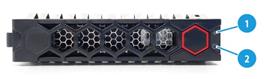
3SFF drive backplane (1SAS/SATA+2UniBay)
The 3SFF drive backplane is installed on the front of the chassis and supports up to three 2.5-inch drives, including one SAS/SATA drive and two SAS/SATA/NVMe drives. Drive slot 2 can be replaced with a SATA M.2 adapter module. For the drive slot numbering, see Figure 9.
Figure 12 3SFF drive backplane
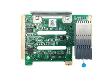
Table 13 3SFF drive backplane component
|
SN |
Description |
Silkscreen |
|
1 |
Data, AUX and power 3-in-1 connector |
- |
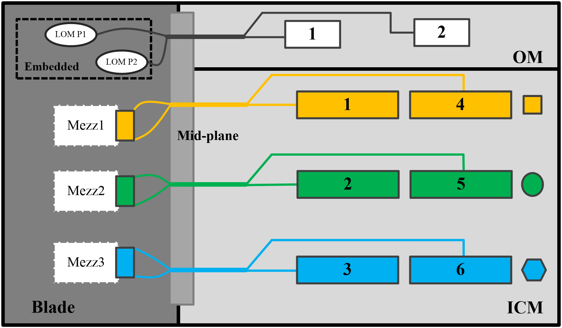
Internal networking
The blade server access the network through an interconnection module. The interconnection module provides the internal interconnection with blade servers through the infix backplane, and provides uplink interconnection interfaces for blade servers through the panel interfaces. The chassis may contain up to 6 interconnection modules. Among them, the interconnection modules in slots 1 and 4, 2 and 5, and 3 and 6 are interconnected through the internal ports of the chassis to form three pairs. Each pair can be used as a switching plane. You may configure them as active or standby based on service needs.
Internal wiring method of the blade server chassis is shown in Figure 13. Where:
· The onboard NIC is connected to the active and standby OM modules.
· Mezzanine module 1 is connected to interconnect modules in slot 1 and slot 4.
· Mezzanine module 2 is connected to interconnect modules in slot 2 and slot 5.
· Mezzanine module 3 is connected to interconnect modules in slot 3 and slot 6.
Figure 13 Internal wiring method of the blade server chassis
B/D/F information about the server
The B/D/F information of the server may change with the PCIe card configuration. Users can obtain the B/D/F information of the server through the following ways:
· BIOS serial port logs: If serial port logs have been collected, users can query the B/D/F information of the server by searching the keyword "dumpiio".
· UEFI Shell: Users can obtain the B/D/F information of the server by using the pci command. For details on how to use the pci command, use the help pci command.
· The way to obtain the B/D/F information varies depending on the operating system. The specific ways are as follows:
¡ Linux OS: You can execute the lspci -vvv command to obtain the B/D/F information of the server.
|
|
NOTE: If the operating system does not support the lspci command by default, you can obtain it through the yum source and install the pci-utils package. |
¡ Windows OS: After installing the pciutils package, execute the lspci command to obtain the B/D/F information of the server.
¡ VMware OS: The VMware OS supports the lspci command by default. You can obtain the information by executing the lspci command.
Component installation guidelines
SAS/SATA drive
· The drives are hot swappable.
· As a best practice, install drives that do not contain RAID information.
· If you are using the drives to create a RAID, follow these restrictions and guidelines:
To avoid degraded RAID performance or RAID creation failures, make sure all drives in the RAID are the same type (HDDs or SSDs) and have the same connector type (SAS or SATA).
· For efficient use of storage, use drives that have the same capacity to build a RAID. If the drives have different capacities, the lowest capacity is used across all drives in the RAID.
· If one drive is used by several logical drives, RAID performance might be affected and maintenance complexities will increase.
· If HDDs are frequently inserted and removed with intervals of less than 30 seconds, the HDDs may fail to be identified by the system.
NVMe drive
· Whether or not NVMe drives support hot swapping and managed hot removal is related to the operating system. You can query the compatibility relationship between the two through the OS compatibility query tool.
· As a best practice, install drives that do not contain RAID information.
· As a best practice, all NVMe drives forming a RAID have the same capacity. When the NVMe drive capacities are different, the system regards the capacity of all NVMe drives as the smallest capacity among them. For NVMe drives with a larger capacity, their excess capacity cannot be used to configure the current RAID or other RAIDs.
· To hot insert NVMe drives, insert the drives steadily without pauses to prevent the operating system from being stuck or restarted.
· Do not hot swap multiple NVMe drives at the same time. As a best practice, hot swap NVMe drives one after another at intervals longer than 30 seconds for the operating system to identify the installed or removed NVMe drive. If you insert multiple NVMe drives in a short period of time, the system might fail to identify the drives
NVMe VROC module
Table 14 describes the NVMe VROC modules supported by the server and their specifications.
Table 14 NVMe VROC module specifications
|
Model |
Description |
Supported RAID level |
|
NVMe-VROC-Key-i |
NVMe VROC module Intel edition, supports Intel NVMe drives only. |
RAID 0/1/5/10 |
|
NVMe-VROC-Key-P |
NVMe VROC module advanced edition, supports any brand of NVMe drives. |
RAID 0/1/5/10 |
|
NVMe-VROC-Key-S |
NVMe VROC module standard edition, supports any brand of NVMe drives. |
RAID 0/1/10 |
Riser card and PCIe card
Compatibility between the riser card and PCIe card
Table 15 PCIe card form factor
|
Short name |
Full name |
|
LP card |
Low Profile card |
|
FHHL card |
Full Height, Half Length card |
|
FHFL card |
Full Height, Full Length card |
|
HHHL card |
Half Height, Half Length card |
|
HHFL card |
Half Height, Full Length card |
Table 16 Shows the compatibility between the riser card and PCIe card.
Table 16 Compatibility between the riser card and PCIe card
|
Riser card model |
Installation location supported by the riser card |
PCIe slot or interface description |
PCIe device supported by the PCIe connector |
CPU |
|
RC-LP |
PCIe riser card connector |
PCIe 3.0 x16 (16, 8, 4, 2, 1) |
LP card |
CPU 2 |
|
· For the specific location of the PCIe riser card connector on the system board, see "System board layout." · The PCIe connector on the riser card is not available when the CPU is not present. · Smaller PCIe cards can be inserted into the PCIe connector corresponding to larger PCIe cards. For example, LP cards can be inserted into the PCIe connector corresponding to FHFL cards. · PCIe 3.0 x16 (16, 8, 4, 2, 1): ¡ PCIe 3.0: Third-generation signal rate. ¡ x16: Connector bandwidth. ¡ (16, 8, 4, 2, 1): Compatible bus bandwidths, including x16, x8, x4, x2 and x1. |
||||
Installation guidelines
When a storage controller is installed onto the storage controller connector on the system board, no riser card and PCIe card can be installed on the blade server. For the specific location of the storage controller connector, see "System board layout."
Storage controller and its power fail safeguard module
Storage controller
Table 17 shows the front mezzanine storage controller and the onboard VROC array controller supported by the blade server.
Table 17 Storage controller description
|
Storage controller model |
Installation position |
Supported drive type |
Power fail safeguard module |
Installation method |
|
|
Embedded VROC array controller |
Embedded on the system board, does not need to be installed by users |
SATA HDD/SSD |
Not supported |
Not involved |
|
|
RAID-P5408-Mf-8i-4GB |
Storage controller connector for system board |
SAS/SATA HDD/SSD |
Supported, SCAP-LSI-G3 supercapacitor required (Flash embedded in the storage controller) |
See "Installing a storage controller and a power fail safeguard moduleInstalling a ." |
|
|
RAID-P2404-Mf-4i-2GB |
Storage controller connector for system board |
SAS/SATA HDD/SSD |
Supported, SCAP-PMC-G3 supercapacitor required (Flash embedded in the storage controller) |
||
|
RAID-P4408-Mf-8i-2GB |
Storage controller connector for system board |
SAS/SATA HDD/SSD |
Supported, SCAP-PMC-G3 supercapacitor required (Flash embedded in the storage controller) |
||
|
HBA-H5408-Mf-8i |
· Storage controller connector for system board |
SAS/SATA HDD/SSD |
Not supported |
NA |
|
Table 18 shows the embedded VROC array controller specifications. For the specifications of other storage controllers, use the server-compatible parts query tool on the official website.
Table 18 Embedded VROC array controller
|
Model Item |
|
|
Type |
8 internal SATA ports |
|
Number of internal ports |
6 Gbps SATA 3.0 Supports drive hot swapping |
|
Drive interface |
PCIe 3.0 x4 bit width |
|
PCIe connector |
RAID 0/1/5 |
|
Location/Size |
Location: Embedded on the PCH of the system board |
|
Built-in cache memory |
N/A |
|
Flash |
N/A |
|
Power fail safeguard module |
Not supported |
|
Battery connector |
N/A |
|
Firmware upgrade |
Upgrade with the BIOS |
|
Note: If you want to use the embedded VROC array controller, you need to choose a straight-through module that supports up to 4 ports (model: PTH-PT104-Mf-4L). |
|
Power fail safeguard module
A power fail safeguard module provides a flash card and a supercapacitor. There are two types of flash cards: One needs to be installed to the storage controller; the other is embedded in the storage controller and does not need to be installed by users.
In the event of an unexpected power failure of the server system, the supercapacitor can power the flash card for more than 20 seconds, during which the cached data is transferred from the DDR memory of the storage controller to the flash card. Since the flash card is a non-volatile storage medium, it enables permanent storage of cached data or until the server system is powered up and the storage controller retrieves such data.
|
|
NOTE: After the supercapacitor is installed, the power may be low. No action is required at this time. The internal circuitry will automatically charge and enable the supercapacitor when the server is powered on. You can query the supercapacitor status through HDM or OM. |
Note on the expiration of the supercapacitor:
· A supercapacitor has a lifespan of 3 to 5 years.
· If the lifespan of a supercapacitor expires, a supercapacitor exception might occur. The system notifies users of supercapacitor exceptions by using the following methods:
¡ For a PMC storage controller, the status of the flash card becomes Abnormal_status code. You can check the status code to identify the exception. For more information, see H3C Servers HDM Online Help.
¡ For an LSI supercapacitor, the status of the flash card displayed by HDM becomes Abnormal.
¡ HDM will generate SDS log records. For details on how to query the SDS log, see H3C Servers HDM Online Help.
· When the supercapacitor expires, it needs to be replaced in time. Otherwise, the power fail data safeguard function of the storage controller will fail.
|
|
NOTE: After replacing the expired supercapacitor, check the logical drive cache status of the storage controller. If the logical drive cache of the storage controller is turned off, re-enable the cache related settings to enable the power fail safeguard function. For details, see H3C Servers HDM Online Help. |
GPU
Due to structural limitations, the GPU and the storage controller cannot be installed at the same time. The GPU is installed on the PCIe riser card connector, and the storage controller is installed on the storage controller connector. For the specific location of both connectors, see "System board layout."
NIC
Standard PCIe NIC installation guidelines
Due to structural limitations, the standard PCIe NIC and the storage controller cannot be installed at the same time. The standard PCIe NIC is connected via the riser card, which is installed on the PCIe riser card connector, and the storage controller is installed on the storage controller connector. For the specific location of both connectors, see "System board layout."
Mezzanine NIC installation guidelines
· The blade server supports installing a maximum of three mezzanine NICs.
· When installing the mezzanine NIC, make sure the corresponding processor is present. See "PCIe connector" for the specific relations.
· The mezzanine NIC and the interconnect module are interconnected through the chassis backplane. There is a slot correspondence between them. When installing the mezzanine NIC, ensure that the interconnect module in the corresponding slot is present. See "Internal networking" for the specific relations.
SATA M.2 SSD module
· A SATA M.2 SSD module must be used together with a SATA M.2 SSD adapter, and the server can install a maximum of two SATA M.2 SSD modules.
· The SATA M.2 SSD modules are hot swappable.
· As a best practice, install SATA M.2 SSD modules that do not contain any RAID information.
· For efficient use of storage, use SATA M.2 SSD modules that have the same capacity to build a RAID. If the SATA M.2 SSD modules have different capacities, the lowest capacity is used across all SATA M.2 SSD modules in the RAID.
SATA M.2 SSD adapter module
The SATA M.2 SSD adapter module supports hot swapping.
DIMMs
This section introduces the basic concept of DIMM, DIMM mode and DIMM installation guidelines.
About DIMMs
DIMMs include DDR4 and PMem 200 DIMMs. DDR4 DIMMs include LRDIMM and RDIMM.
1. DDR4 and PMem 200
· DDR4 is the most common type of DIMM. The data in DDR4 will be lost in the event of an unexpected power failure of the server system.
· PMem 200 has the following two features:
¡ Compared with DDR4, PMem 200 has a larger capacity for a single memory module.
¡ PMem 200 (such as Barlow Pass) has data protection in case of power failure. Data in PMem 200 will not be lost in the event of unexpected power failure of the server system.
2. RDIMM and LRDIMM
· RDIMM provides address parity protection.
· LRDIMM provides a larger capacity and bandwidth for the system.
3. Rank
The number of ranks is usually 1, 2, 4, or 8, generally abbreviated as 1R/SR, 2R, 4R, 8R, or single-rank, dual-rank, quad-rank, or 8-rank.
· A 1R DIMM has a set of DIMM chips that will be accessed when data is written to or read from the DIMM.
· A 2R DIMM is equivalent to a module containing two 1R DIMMs, but only one rank can be accessed at a time.
· A 4R DIMM is equivalent to a module containing two 2R DIMMs, but only one rank can be accessed at a time.
· A 8R DIMM is equivalent to a module containing two 4R DIMMs, but only one rank can be accessed at a time.
When writing or reading data in a DIMM, the server memory control subsystem will select the correct rank from the DIMM.
4. DIMM specifications
DIMM specifications can be identified by the label on it.
Figure 14 DIMM identification
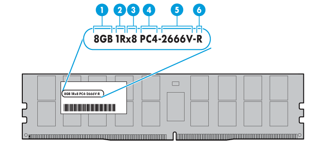
Table 19 Description of DIMM identification
|
SN |
Description |
Definition |
|
1 |
Capacity |
· 8 GB · 16 GB · 32 GB |
|
2 |
Number of ranks |
· 1R = The number of ranks is 1. · 2R = The number of ranks is 2. · 4R = The number of ranks is 4. · 8R = The number of ranks is 8. |
|
3 |
Data width |
· x4 = 4-bit · x8 = 8-bit |
|
4 |
DIMM generation |
DDR4 |
|
5 |
DIMM equivalent speed |
· 2133P: 2133 MHz · 2400T: 2400 MHz · 2666V: 2666 MHz · 2933Y:2933 MHz |
|
6 |
DIMM type |
· R = RDIMM · L = LRDIMM |
DIMM mode
The blade server supports the following DIMM modes to protect the data in the DIMM.
|
|
NOTE: Independent Mode is the default mode and is not available on the BIOS interface. |
· Independent Mode (default)
· Mirror Mode
· Memory Rank Sparing
Independent Mode
Standard ECC can correct 1-bit memory errors and detects multi-bit memory errors. When standard ECC detects multi-bit errors, it informs the server and stops the server. Independent mode can prevent multi-bit errors from occurring on the server, and correct 1-bit or 4-bit memory errors (when the errors are located on the same DDR4 on the DIMM). Independent mode can provide more powerful protection and correct memory errors that cannot be corrected by standard ECC and cause the server to shut down.
Mirror Mode
Mirror mode uses a portion of the system memory for mirroring, to improve system stability and prevent uncorrectable memory errors that cause server downtime. When an uncorrectable error is detected in a memory channel, the blade server will fetch data from the mirrored memory. The mirror mode is a channel-level memory mode, for example, CH2 is the mirror for CH1, CH3 for CH2, and CH1 for CH3.
Memory Rank Sparing
Use a portion of the system memory rank as backup rank to improve system stability. When this feature is enabled, if the correctable errors that occur in a non-backup rank exceeds a specific threshold, the blade server enables the backup rank to replace and disable the failed rank.
DIMM installation guidelines
The blade server supports 1 or 2 CPUs, each CPU supports 8 channels, and each channel supports 2 DIMMs, that is, one CPU supports 16 DIMMs and 2 CPUs support 32 DIMMs. The server supports DDR4-only configuration and also a mixture of PMem 200 and DDR4.
|
|
NOTE: The operating frequency of the DIMM can be up to 3200 MHz only when both of the following conditions are met: · Use a CPU with a maximum DIMM frequency of 3200 MHz. · Use a DIMM with a maximum frequency of 3200 MHz. · Only one DIMM is configured in each of the channels where DIMM is configured. |
DIMM and CPU compatibility
Table 20 describes the DIMM and CPU compatibility.
Table 20 DIMM and CPU compatibility
|
CPU type |
CPU-compatible DIMM type @ frequency |
Maximum DIMM capacity supported by a single CPU (DDR4 and PMem included) |
|
· Intel Ice Lake |
· DDR4 @3200 MHz · PMem 200 @2666 MHz |
6 TB |
|
Montage Jintide C3 series |
DDR4 @3200 MHz |
6 TB |
DIMM operating frequency
|
|
NOTE: You can query the DIMM frequency and the maximum DIMM frequency supported by the CPU with the server-compatible part query tool. In the query tool, query the DIMM frequency by the part name of "memory module". Query the maximum DIMM frequency supported by the CPU by the part name of "processor". |
· The operating frequency of DIMM in the server is equal to the lower of the DIMM frequency or the maximum DIMM frequency supported by the CPU. For example, if the DIMM frequency is 2666 MHz and the maximum DIMM frequency supported by the CPU is 3200 MHz, then the DIMM will run at 2666 MHz.
Guidelines for installing only DDR4 DIMMs
· Make sure the corresponding CPU is installed.
· DIMMs of different specifications (type, capacity, rank, data width, rate) cannot be mixed, that is, all DIMMs installed on the server have the same product code. Query the product code information with the server-compatible part query tool.
· In addition to the above guidelines, different DIMM modes have their own specific guidelines, as described in Table 21. Note that when the actual DIMM installation does not meet these specific guidelines, the system will use the default Independent mode regardless of the DIMM mode configured by the user.
Table 21 Specific installation guidelines for different DIMM modes
|
Memory mode |
DIMM population requirements |
|
Independent Mode (default) |
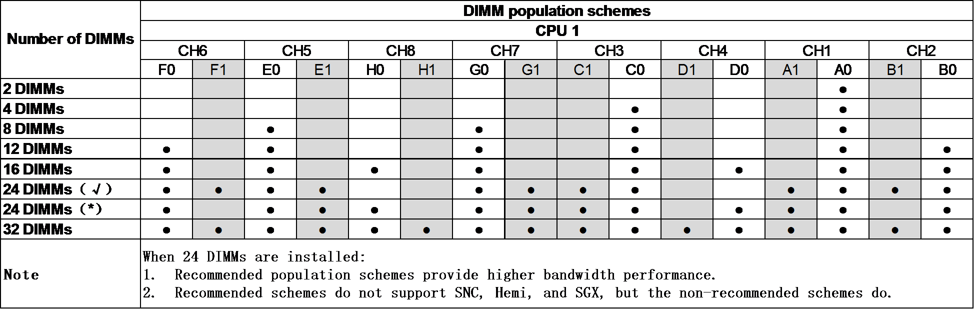
· Strictly follow the DIMM population schemes: · If one processor is present, see Figure 15. · If two processors are present, see Figure 16 and Figure 17. |
|
Mirror Mode |
· A minimum of two DIMMs for a processor. · This mode does not support DIMM population schemes that are not recommended. ¡ If one processor is present, see Figure 15. ¡ If two processors are present, see Figure 16 and Figure 17. |
|
Memory Rank Sparing |
· Make sure no less than two ranks are configured for each channel. · Strictly follow the DIMM population schemes: ¡ If one processor is present, see Figure 15 ¡ If two processors are present, see Figure 16 and Figure 17. |
Figure 15 1-CPU DIMM configuration guidelines

Figure 16 2-CPU DIMM configuration guidelines (1)

Figure 17 2-CPU DIMM configuration guidelines (2)
Guidelines for installing a mixture of PMem 200 and DDR4 DIMMs
· Make sure the corresponding CPU is installed.
· Make sure that the installed PMem has not been used in other products. Otherwise it may not work after installation.
¡ DDR4 DIMMs of different specifications (type, capacity, rank, data width, rate) cannot be mixed, that is, all DDR4 DIMMs installed on the server have the same product code. PMem 200 DIMMs of different specifications cannot be mixed, that is, the product codes of all PMem 200 DIMMs installed on the server must be the same. For details on the product code, see the server-compatible part query tool.
¡ The frequency of the DIMM installed for each CPU must not exceed the maximum DIMM frequency supported by the CPU. For the frequency of the DIMM and the maximum DIMM frequency supported by the CPU, see the server-compatible part query tool.
· PMem supports the corresponding operating modes. The corresponding guidelines should be met:
¡ When AD operating mode is supported, these requirements need to be met: DIMM capacity configured under a single CPU (total capacity of DDR4 and PMem) ≤ The maximum DIMM capacity supported by a single CPU (total capacity of DDR4 and PMem); The maximum DIMM capacity supported by a single CPU (total capacity of DDR4 and PMem) is shown in Table 20.
¡ When MM operating mode is supported, these requirements need to be met:
- The DIMM capacity configured under a single CPU (total capacity of DDR4 and PMem) ≤ The maximum DIMM capacity supported by a single CPU (total capacity of DDR4 and PMem).
- The capacity ratio of DDR and PMem configured for each CPU should be limited from 1:4 to 1:16.
¡ For the operating modes supported by different capacity ratios of PMem and DDR and how to configure the operating modes, see PMem 200 User Guide and Appendix.
The DIMM installation guidelines for mixing PMem 200 and DDR4 are shown in Figure 18, Figure 19, and Figure 20.
Figure 18 PMem 200 and DDR4 DIMM configuration guidelines (1-CPU)
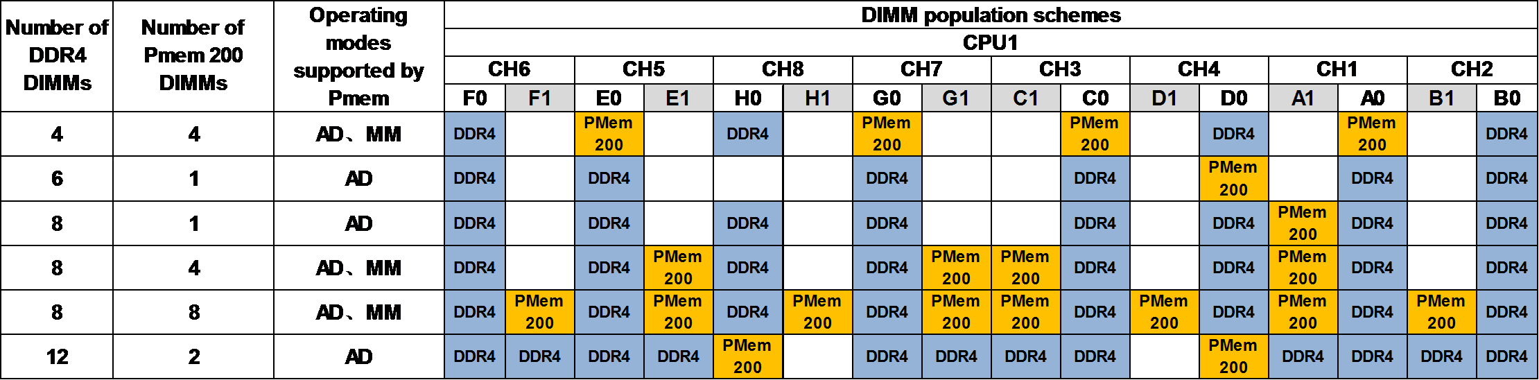
Figure 19 PMem 200 and DDR4 DIMM configuration guidelines (2-CPU) (1)
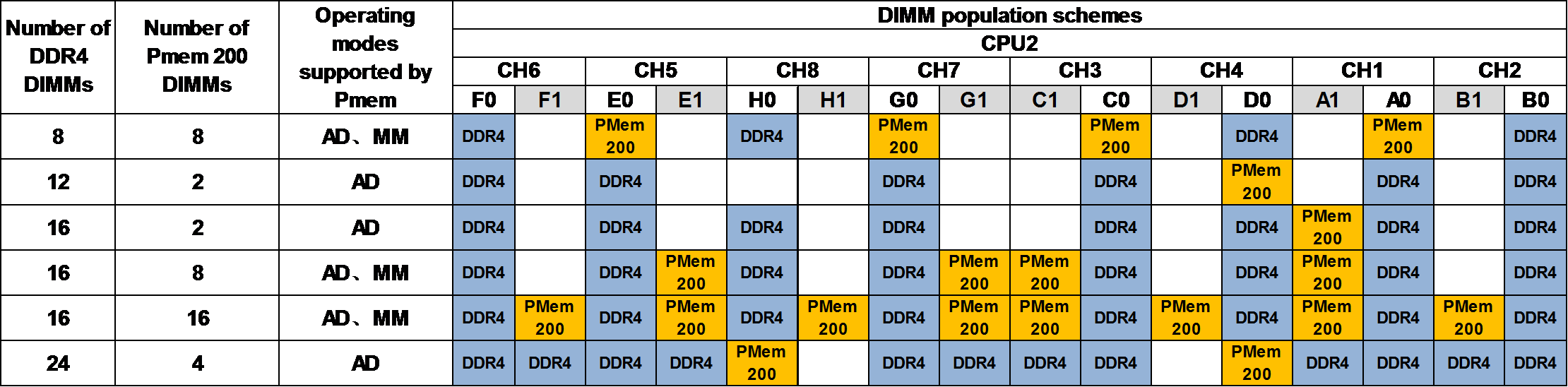
Figure 20 PMem 200 and DDR4 DIMM configuration guidelines (2-CPU) (2)

CPU
Guidelines
You can install one or two processors.
· To avoid damage to a processor or the system board, only H3C authorized or professional server engineers can install, replace, or remove a processor.
· Make sure the processors on the server are the same model.
· A CPU moduel is suffixed with U, indicating the CP supports single-socket operation only. Use "Meaning of CPU product model suffix" to identify processor model suffixes.
· CPUs of the same model support two types of heatsinks: one with sparse fins and one with dense fins. Heatsinks with sparse fins labeled with Front must be installed on CPU 2 and the heatsinks with dense fins labeled with Rear must be installed on CPU 1. For more information about the position of CPUs, see "System board layout."
· For the server to operate correctly, make sure processor 1 is in position. For more information about processor locations, see "System board layout."
· The pins in the processor sockets are very fragile and prone to damage. Install a protective cover if a processor socket is empty.
· To prevent static electricity from damaging the electronic components, wear an ESD wrist strap before operation and ground the other end of the ESD wrist strap.
Meaning of CPU product model suffix
If the CPU model is UN-CPU-INTEL-8360Y-S, then it is suffixed with "Y" (abbreviated as CPU model suffix). You can query the CPU model supported by the server with the server-compatible part query tool.
Table 22 describes meaning of the Intel Ice Lake CPU model suffix.
Table 22 Intel Ice Lake CPU model suffix description
|
CPU model suffix |
Suffix meaning |
Suffix description |
|
N |
NFV Optimized |
Supports NFV scenario optimization. |
|
T |
High Tcase |
Supports high temperature specifications. |
|
U |
Single Socket |
Supports single-socket operation only. |
|
V |
SaaS optimized SKU for orchestration efficiency targeting high density, lower power VM environment (70% CPU utilization) |
SaaS scenario optimized for VM applications with high density and lower power. |
|
P |
laaS optimized SKU for orchestration efficiency targeting higher frequency for VM Markets (70% CPU utilization) |
IaaS scenario optimization for VM applications with higher frequency. |
|
Y |
Speed Select Technology – Performance Profile |
Supports Intel SST technology, with configurable number of cores and core frequency. |
|
S |
Max SGX enclave size SKUs (512 GB) |
Maximum SGX enclave security container (512 GB) |
|
Q |
Liquid cooling (Temperature Inlet to cold plate = 40℃, ICX TTV Ψca (case-to-fluid inlet resistance)=0.06℃/W) |
Liquid cooling dedicated CPU model |
|
M |
Media Processing Optimized |
Media processing scenario optimization. |
|
NOTE: The list is for reference only. For detailed information, see the official website of Intel. |
||
Installing or removing the blade server
This section describes the specific steps for installing or removing the blade server.
|
|
NOTE: For specific steps, see the "parts installation & replacement video." |
Prerequisites
Take the following ESD prevention measures:
· Wear antistatic clothing.
· Wear an ESD wrist strap and make sure it makes good skin contact and is reliably grounded.
· Do not wear any conductive objects, such as jewelry or watches.
· Before removing the blade server, make sure you back up the data, stop all services, and power off the server.
· When you replace a component, examine the slot and connector for damages. Make sure the pins are not damaged (bent for example) and do not contain any foreign objects.
· You might also remove other components. For the removed components to be reinstalled correctly, record their positions and connections before removal, for example, taking pictures of cable connection and drive installation positions, or labeling cables.
· For more information about installation principles of blade servers, see the user guide for the server.
Installing the blade server
1. Remove the blade server blank. Press the two latches at both sides at the same time and pull the blank out.
2. Take the half-width blade server out of the antistatic bag.
3. Press the buttons to release the locking levers at two sides.
4. Insert the server into the enclosure slowly and horizontally, and then close the locking levers.
Removing the blade server
1. Remove the half-width blade server. Press the buttons to release the locking levers at two sides, and pull the server out of the enclosure slowly and horizontally.
2. Put the server into an antistatic bag. Powering on and powering off the blade server
Powering on the blade server
This section describes how to power on the blade server.
|
|
NOTE: If the server is connected to external storage devices, make sure the server is the first device to power off and then the last device to power on. This restriction prevents the server from mistakenly identifying the external storage devices as faulty devices. |
Supported power-on methods
Table 23 describes power-on methods supported by the blade server.
Table 23 Blade server power-on methods
|
Power-on method |
Application scenario |
|
Powering on the blade server together with the enclosure |
· The blade server is installed and the chassis is not powered on. |
|
Powering on the blade server by pressing the power on/standby button |
The chassis is powered on, the blade server is installed but is in a down state. The blade server system power LED is steady amber. |
|
Powering on the blade server from the OM Web interface |
|
|
Powering on the blade server by using an OM command |
|
|
Powering on the blade server through the blade server HDM Web UI. |
Prerequisites
Before you power on the server, you must complete the following tasks:
· Install the server and internal components correctly.
· Connect the server to a power source.
· As a best practice for the internal components to operate correctly, do not perform the power on action immediately after powering off the server. Wait for over 30 seconds for HDD drives to stop rotation and electronic components to be powered off completely
Guidelines
If the blade server is successfully powered on, the system power LED turns steady green. For more information about the position of the LEDs, see “LEDs and buttons.”
Procedure
Powering on the blade server together with the enclosure
If you want to power on the server together with the enclosure, configure the power-on delay for slots first. After configuration, power on the enclosure, and the blade server is powered on automatically based on previous settings. No extra action is required.
For more information about the power-on delay for slots, see the OM online help.
Powering on the blade server by pressing the power on/standby button
Press the power on/standby button to power on the server. For information about the position of the power on/standby button, see “LEDs and buttons.”
Powering on the blade server from the OM Web interface
Access the server management page from the OM Web interface and power on the server. For more information, see the OM online help.
Powering on the blade server by using an OM command
Execute the psu-blade command to power on the server. For more information, see the OM command reference.
Method 5: Power on the blade server through the blade server HDM Web UI.
The blade server can be powered on through the power management function of the blade server HDM Web UI. For the specific operations, see the H3C Servers HDM Online Help.
Powering off the blade server
This section describes how to power off the blade server.
|
|
NOTE: The blade server will be powered off when the chassis is powered off. |
Supported power-off methods
Table 24 describes power-off methods supported by the blade server.
Table 24 Blade server power-off methods
|
Power-off method |
Application scenario |
|
Powering off the server from its operating system |
Both the chassis and the blade server are powered on and the blade server is working correctly. |
|
Powering off the server from the OM Web interface |
|
|
Powering off the server by using an OM command |
|
|
Power off the blade server through the power management function on the blade server HDM Web UI. |
|
|
Power off the blade server through the power on/standby button on the front panel of the blade server. |
Both the chassis and the blade server are powered on, but the blade server is abnormal. |
Prerequisites
Before powering off the server, you must complete the following tasks:
· Back up all critical data.
· Make sure all services have stopped or have been migrated to other servers.
Guidelines
If the blade server is successfully powered off, the system power LED turns steady amber. For more information about the position of the system power LED, see "LEDs and buttons."
Powering off the server from its operating system
Use the SUV cables to connect a monitor, mouse, and keyboard to the blade server, and then shut down the operating system to power off the server.
Powering off the server from the OM Web interface
Access the server management page from the OM Web interface and power off the server. For more information, see OM online help.
Powering off the server by using an OM command
Execute the psu-blade command to power off the server. For more information, see the OM online help.
Powering off the server from the HDM Web interface
The blade server can be powered off through the power management function of the blade server HDM Web UI. For the specific operations, see the H3C Servers HDM Online Help.
Powering off the server forcedly by pressing the power on/standby button
|
|
NOTE: This method forces the server to enter standby mode without properly exiting applications and the operating system. Use this method only when the server system crashes. For example, a process gets stuck. |
Press and hold the power on/standby button for more than five seconds to power off the server.
Configuring the blade server
The following information describes the procedures to configure the server after the server installation is complete.
Configuration flowchart
Figure 21 Configuration flowchart

Default login parameters
The default IP address, default username and password for the chassis OM management interface are listed in Table 25.
Table 25 Default OM parameters
|
Item |
Default value |
|
Username |
Admin |
|
Password |
Password@_ |
|
IP address of the management port |
192.168.100.100/24 |
The default IP address, default username and password for the blade server HDM management port are shown in Table 26.
Table 26 Default HDM parameters
|
Item |
Default value |
|
Username |
Admin |
|
Password |
Password@_ |
|
IP address of the management interface |
Obtained from the DHCP server |
Connecting the blade server to a network
Connecting through the management module
Use either of the following methods to connect the blade server to the network through the management module:
· Connect the network cable to one of the four service ports on the management module.
Figure 22 Service ports on the management module

· The management module provides a management port (MGMT) to which a network cable is connected. Thought this port, you can log in to the chassis OM and the HDM of the blade server to monitor the operating status of the chassis and the blade server and set basic information.
Connecting through ICMs
The mezzanine network adapter on each blade server has a corresponding ICM. To connect a blade server to the network through an ICM, make sure the corresponding ICM are present. For more information about mezzanine network adapter and ICM mapping relations, see "Internal networking."
Verifying the blade server status
1. After powering on the server, perform the following tasks to make sure that the server is working correctly. Power on the blade server. For more information, see "Powering on the blade server."
· Verify that the state of the four LEDs on the front panel of the blade server are as expected. For more information about the LEDs, see "LEDs and buttons."
· Log in to OM and verify that the firmware versions are as expected. If not, upgrade the firmware. For more information, see the OM online help.
· Log in to OM and verify that the server is operating correctly. If not, troubleshoot the server.
Modifying default parameters
Modifying the default user password of OM
1. Log in to OM. For more information, see the OM user guide.
2. Modify the OM default user password. For more information, see the OM online help
Modifying the default IP address of the OM module
1. Log in to OM. For more information, see the OM user guide
2. Modify the default IP address of the OM module. For details on how to modify it, see OM Online Help.
Modifying default parameters
Modifying the default user password of HDM
You cannot modify HDM password from OM.
To modify the default password of HDM:
1. Log in to HDM. For more information, see "Accessing the blade server HDM."
2. Modify the HDM default user password. For more information about the password requirements and password setting method, see H3C Servers HDM Online Help.
Modifying the default IP address of HDM
Modifying IP through OM
1. Log in to OM. For more information, see the OM user guide.
2. Modify the HDM default IP address. For more information, see the OM online help.
Modifying IP through HDM
1. Log in to HDM. For more information, see "Accessing the blade server HDM."
2. Modify the HDM default IP address. For more information, see H3C Servers HDM Online Help
Logging into the blade server operating system
For more information, see "Logging in to the blade server operating system."
Configuring basic BIOS settings
Setting the server boot order
The server has a default boot order. Users can modify the boot sequence of the blade server as needed.For the default boot order and the procedure of changing the server boot order, see the BIOS user guide for the server.
Setting the BIOS passwords
BIOS passwords include a boot password as well as an administrator password and a user password for the BIOS setup utility. By default, no passwords are set.
To prevent unauthorized access and changes to the BIOS settings, set both the administrator and user passwords for accessing the BIOS setup utility. Make sure the two passwords are different.
After setting the administrator password and user password for the BIOS setup utility, you must enter the administrator password or user password each time you access the BIOS setup utility.
· To obtain administrator privileges, enter the administrator password.
· To obtain the user privileges, enter the user password.
For the difference between the administrator and user privileges and guidelines for setting the BIOS passwords, see the BIOS user guide for the server.
Configuring RAID
Configure physical and logical drives (RAID arrays) for the server.
The supported RAID levels and RAID configuration methods vary by storage controller model. For more information, see the storage controller user guide for the server.
Installing the operating system and hardware drivers
This section introduces how to install the operating system and drivers.
Installing an OS
The blade server is compatible with many types of operating systems such as Windows and Linux. For details, see the OS compatibility query tool.
For details on how to install the OS, see the OS installation guide.
Installing hardware drivers
For newly installed hardware to operate correctly, the operating system must have the required hardware drivers.
To install a hardware driver, see the operating system installation guide for the server.
|
|
NOTE: To avoid hardware unavailability caused by an update failure, always back up the drivers before you update them. |
Replacing hardware options
This section describes replaceable parts of the blade server and the detailed procedures for part replacement.
|
|
NOTE: If you are replacing multiple hardware options, read their replacement procedures and identify similar steps to streamline the entire replacement procedure. |
Replaceable parts and their videos
Set out below are the specific method of replacing each part and the replaceable parts of the server:
· SAS/SATA drive (Replacing a SAS/SATA drive)
· NVMe drive (Replacing an NVMe drive)
· Riser card and PCIe card (Replacing the riser card and PCIe card)
· Storage controller and its power fail safeguard module (Replacing the riser card and PCIe)
· Straight-through card (Replacing the straight-through card)
· GPU card (Replacing the GPU card)
· NIC (Replacing the straight-through card)
· SATA M.2 SSD module (Replacing a SATA M.2 SSD)
· SATA M.2 SSD adapter module (Replacing a SATA M.2 SSD adapter)
· NVMe VROC module (Replacing the NVMe VROC module)
· DIMMs (Replacing the DIMM)
· CPU (Replacing the GPU card and Expanding the processor)
· TPM/TCM (Installing and setting up a TCM or TPM)
· System battery (Replacing the system battery)
· System board (Replacing the system board)
· Drive backplane (Replacing a drive backplane)
Replacing a SAS/SATA drive
To configure RAID settings after the drive is replaced, see the storage controller user guide for the server.
Operation scenario
· The drive fails.
· Expand the drive.
· Replace the drive with full space.
· Replace the drive with another model.
· The drive hinders maintenance of other parts.
Prerequisites
Take the following ESD prevention measures:
· Wear antistatic clothing.
· Wear an ESD wrist strap and make sure it makes good skin contact and is reliably grounded.
· Do not wear any conductive objects, such as jewelry or watches.
· Identify the position of the drive to be replaced.
· To replace a drive that is installed with an operating system and is not configured with a RAID or is in a non-redundancy array, back up data, stop all services, and power off the blade server. For more information, see "Powering off the blade server."
· When you replace a component, examine the slot and connector for damages. Make sure the pins are not damaged (bent for example) and do not contain any foreign objects.
· You might also remove other components. For the removed components to be reinstalled correctly, record their positions and connections before removal, for example, taking pictures of cable connection and drive installation positions, or labeling cables.
· Identify the RAID array information of the drive to be replaced. To replace a drive that is not configured with a RAID, back up all data if the old drive is full or the new drive is of a different model
· Understand the guidelines for installing a SAS/SATA drive: SAS/SATA drive
Removing a SAS/SATA drive
1. Remove the drive:
¡ To remove an SSD, press the button on the drive panel to release the locking lever, and then hold the locking lever and pull the drive out of the slot.
¡ To remove an HDD, press the button on the drive panel to release the locking lever. Pull the drive 3 cm (1.18 in) out of the slot. Wait for a minimum of 30 seconds for the drive to stop rotating, and then pull the drive out of the slot.
2. Remove the drive carrier. Remove the screws that secure the drive and then remove the drive from the carrier.
Installing a SAS/SATA drive
1. (Optional) Please confirm in advance whether the newly installed SAS/SATA drive contains RAID information. If yes, please delete the RAID information.
2. (Optional) Attach the drive to the drive carrier. Place the drive in the carrier and then use four screws to secure the drive into place.
3. (Optional) Remove the blank from the drive slot, if any. Pressing the red button on the blank to the right, pull the blank out of the slot.
4. Install the drive. Press the button on the drive panel to release the locking lever, and then insert the drive into the drive slot.
5. After the storage controller detects the new SAS/SATA drive, please confirm whether to configure RAID according to the actual situation. For the method of configuring RAID, refer to the storage controller user guide of the product.
Verifying the replacement
Use one of the following methods to verify that the drive has been replaced correctly:
· Verify the drive properties (including capacity) by using one of the following methods:
¡ Log in to OM. For more information, see the OM online help.
¡ Log in to HDM. For more information, see H3C Servers HDM online help.
¡ Access the BIOS. For more information, see the storage controller user guide for the server.
¡ Access the CLI or GUI of the server.
· Observe the drive LEDs to verify that the drive is operating correctly. For more information about drive LEDs, see "LEDs and buttons."
Replacing an NVMe drive
To configure RAID settings after the drive is replaced, see the storage controller user guide for the server.
Operation scenario
· The drive fails.
· Expand the drive.
· Replace the drive with full space.
· Replace the drive with another model.
· The drive hinders maintenance of other parts.
Prerequisites
Take the following ESD prevention measures:
· Wear antistatic clothing.
· Wear an ESD wrist strap and make sure it makes good skin contact and is reliably grounded.
· Do not wear any conductive objects, such as jewelry or watches.
· Identify the position of the drive to be replaced.
· To replace a drive that is installed with an operating system and is not configured with a RAID or is in a non-redundancy array, back up data, stop all services, and power off the blade server. For more information, see "Powering off the blade server."
· When you replace a component, examine the slot and connector for damages. Make sure the pins are not damaged (bent for example) and do not contain any foreign objects.
· You might also remove other components. For the removed components to be reinstalled correctly, record their positions and connections before removal, for example, taking pictures of cable connection and drive installation positions, or labeling cables.
· Identify the RAID array information for the drive to be replaced. To replace a drive that is not configured with a RAID, back up all data if the old drive is full or the new drive is of a different model.
· Understand the guidelines for installing the NVMe drive: NVMe drive.
· For the operating systems that support NVMe drive hot swapping and managed hot removal, see "NVMe drive."
· Perform the predictive hot-swap operation. For the specific steps, refer to the online replacement operation guide of NVMe drive.
Removing an NVMe drive
|
|
NOTE: When you remove multiple NVMe drives, remove the drives one after another at intervals of more than five seconds. |
1. Remove the drive. Press the button on the drive panel to release the locking lever, and then pull the drive out of the slot.
2. Remove the drive carrier, if any. Remove all screws that secure the drive, and then remove the drive from the carrier.
Installing an NVMe drive
1. Read the installation guidelines. See "NVMe drive."
2. Attach the drive to the drive carrier. Place the new drive in the carrier and then use screws to secure the drive into place.
3. Remove the drive blank from the drive slot, if any. Pressing the red button to the right on the blank, pull the blank out of the slot.
4. Install the drive. Press the button on the drive panel to release the locking lever, and then insert the drive into the slot.
5. Clear the RAID information in the newly installed NVMe drive, if any.
6. Configure the RAID according to the real situation. For more information, see the BIOS users guidide
Verifying the replacement
Use the following methods to verify that the drive is installed correctly:
· Verify the drive properties (including capacity) by using one of the following methods:
¡ Log in to HDM. For more information, see H3C Servers HDM Online Help.
¡ Log in to OM. For more information, see the OM online help.
¡ Access the BIOS. For more information, see the BIOS user guide for the server.
¡ Access the CLI or GUI of the server.
· Observe the drive LEDs to verify that the drive is operating correctly.
· After entering the operating system, check whether the NVMe drive capacity and other information are correct.
Replacing the riser card and PCIe card
Operation scenario
· The riser card fails.
· The PCIe card fails.
Prerequisites
· Install another model of riser card.
· Install another model of PCIe card.
· Expand the riser card.
· Expand the PCIe card.
· The riser card or PCIe card hinders maintenance of other parts.
Take the following ESD prevention measures:
· Wear antistatic clothing.
· Wear an ESD wrist strap and make sure it makes good skin contact and is reliably grounded.
· Do not wear any conductive objects, such as jewelry or watches.
· Before replacing, back up data, stop all services, and power off the server. For more information, see "Powering off the blade server."
· Replace the blade server.
· When you replace a component, examine the slot and connector for damages. Make sure the pins are not damaged (bent for example) and do not contain any foreign objects.
· You might also remove other components. For the removed components to be reinstalled correctly, record their positions and connections before removal, for example, taking pictures of cable connection and drive installation positions, or labeling cables.
· For the specific installation guidelines of riser card and PCIe card, see "Riser card and PCIe card."
Removing the riser card and PCIe card
1. Remove the chassis cover. Press the chassis cover unlock button, slide toward the rear of the blade server, and then lift the cover up.
a. Press the chassis cover unlock button and slide toward the rear of the server.
b. Lift the chassis cover up to remove it from the server.
2. Remove the riser card with PCIe card. Lift the riser card up to remove it from the server chassis.
3. Remove the PCIe card from the riser card. Press and open the fixing buckle on the riser card, and then lift the PCIe card up to remove it from the riser card.
Installing the riser card and PCIe card
1. Install the PCIe card to the riser card.
a. Open the fixing buckle on the riser card. Press the locking button on the fixing buckle and open the fixing buckle.
b. (Optional) Remove the PCIe card filler panel. Lift the filler panel up and remove it from the riser card.
c. InstallIng the PCIe card to riser card connector Insert the PCIe card along the PCIe connector on the riser card, and then close the PCIe card fixing buckle.
2. Install the riser card with the PCIe card in the blade server.
a. (Optional) Remove the filler panel. Lift the filler panel up.
b. Install the riser card with the PCIe card in the blade server. Insert the riser card downward as aligning the two mushroom-shaped heads on the riser card with the two notches on the blade server.
3. Install the chassis cover. Place the chassis cover horizontally downward as aligning the mushroom-shaped head on the chassis cover with the groove on the chassis, and slide the chassis cover toward the front of the server until it is locked.
4. Install the blade server.
5. Power on the blade server. For the specific steps, see "Powering on the blade server."
Replacing the storage controller and its power fail safeguard module
This section describes the detailed operating steps for replacing the storage controller and its power fail safeguard module.
Operation scenario
· The storage controller fails.
· Replace the storage controller with another model.
· The storage controller hinders maintenance of other parts.
· The power fail safeguard module fails.
· The power fail safeguard module hinders the maintenance of other parts.
· Expand the storage controller.
· Expand the power fail safeguard module
Prerequisites
· Replace the storage controller with one of the same model. Please specify the information about the storage controller and BIOS to be replaced.
¡ The model, operating mode, and firmware version of the storage controller.
¡ Specify the boot mode of BIOS.
¡ Specify the first boot item setting of the storage controller in the Legacy boot mode.
· To replace the storage controller with another model, back up in advance the data in the drive controlled by the storage controller to be replaced, and clear the RAID configuration information.
Take the following ESD prevention measures:
· Wear antistatic clothing.
· Wear an ESD wrist strap and make sure it makes good skin contact and is reliably grounded.
· Do not wear any conductive objects, such as jewelry or watches.
· Identify the position of the SATA M.2 SSD to be replaced.
· Identify the RAID array information of the SSD to be replaced. To replace an SSD that is not configured with a RAID or is in a non-redundancy RAID array, back up all data.
· Before replacing, make sure that you stop all services and power off the server. For more information, see "Powering off the blade server."
· Remove the blade server.
· When you replace a component, examine the slot and connector for damages. Make sure the pins are not damaged (bent for example) and do not contain any foreign objects.
· You might also remove other components. For the removed components to be reinstalled correctly, record their positions and connections before removal, for example, taking pictures of cable connection and drive installation positions, or labeling cables.
· To learn about the specific installation guidelines of the storage controller and its power fail safeguard module, see "Storage controller and its power fail safeguard module."
Removing the storage controller and its power fail safeguard module
1. Remove the chassis cover. Press the chassis cover unlock button, slide toward the rear of the blade server, and then lift the cover up.
2. (Optional) Remove the supercapacitor.
a. Disconnect the cable between the storage controller and the supercapacitor.
b. Disconnect the fixing buckle of the supercapacitor outward and take out the supercapacitor from the slot.
3. Remove the storage controller. Remove the fixing screws from the storage controller, and then lift the storage controller up to remove it from the blade server.
Installing a storage controller and a power fail safeguard module
1. Install the storage controller. Align the three screw holes in the storage controller with the three threaded studs on the system board, insert the storage controller, and use screws to secure the controller.
2. Install a supercapacitor to the air baffle, if any, and connect the supercapacitor cable to the storage controller.
|
|
NOTE: The accessories delivered with the supercapacitor include a supercapacitor fixing base, an uncoded adapter cable, and an adapter cable with code 0404A0X1. Neither the fixing base nor the uncoded adapter cable will be used. When installing the supercapacitor, fix the supercapacitor directly to the air guide hood of the blade server, and use the adapter cable with code 0404A0X1 to connect the storage controller and the supercapacitor. |
a. Install the supercapacitor onto the air baffle. Tilt the supercapacitor and insert one end of the supercapacitor into the supercapacitor slot, and press the other end into the slot.
b. Use the 0404A0X1 extension cable to connect the supercapacitor to the storage controller.
3. Install the chassis cover. Place the chassis cover horizontally downward as aligning the mushroom-shaped head on the chassis cover with the groove on the chassis, and slide the chassis cover toward the front of the server until it is locked.
4. Installing the blade server
5. Power on the blade server. For the specific steps, see "Powering on the blade server."
Replacing the straight-through card
This section describes the detailed operation steps for replacing the straight-through card.
Operation scenario
· The straight-through card fails.
· Expand the straight-through card.
· The straight-through card hinders maintenance of other parts.
Prerequisites
Take the following ESD prevention measures:
· Wear antistatic clothing.
· Wear an ESD wrist strap and make sure it makes good skin contact and is reliably grounded.
· Do not wear any conductive objects, such as jewelry or watches.
· Before replacing, back up data, stop all services, and power off the server. For more information, see "Powering off the blade server."
· When you replace a component, examine the slot and connector for damages. Make sure the pins are not damaged (bent for example) and do not contain any foreign objects.
· You might also remove other components. For the removed components to be reinstalled correctly, record their positions and connections before removal, for example, taking pictures of cable connection and drive installation positions, or labeling cables.
Removing the straight-through card
1. Remove the chassis cover. Press the chassis cover unlock button, slide toward the rear of the blade server, and then lift the cover up.
2. (Optional) Remove the riser card and PCIe card that prevent users from accessing the straight-through card.
3. Remove the straight-through card. Remove two screws, hold the middle of the straight-through card, lift the straight-through card horizontally, and then put the straight-through card into an ESD bag.
Installing the straight-through card
1. Install the straight-through card. Remove the straight-through card to be installed from the ESD bag, and insert it downward by aligning it with the connector on the main board. Then tighten the two screws.
2. (Optional) Reinstall the removed riser card and PCIe card.
3. Install the chassis cover. Place the chassis cover horizontally downward as aligning the mushroom-shaped head on the chassis cover with the groove on the chassis, and slide the chassis cover toward the front of the server until it is locked.
4. Installing the blade server
5. Power on the blade server. For the specific steps, see "Powering on the blade server."
Replacing the GPU card
This section describes the detailed steps for replacing the GPU card.
Operation scenario
· The GPU card fails.
· Expand the GPU card.
· The GPU card hinders maintenance of other parts.
Prerequisites
Take the following ESD prevention measures:
· Wear antistatic clothing.
· Wear an ESD wrist strap and make sure it makes good skin contact and is reliably grounded.
· Do not wear any conductive objects, such as jewelry or watches.
· Identify the position of the SATA M.2 SSD to be replaced.
· Identify the RAID array information of the SSD to be replaced. To replace an SSD that is not configured with a RAID or is in a non-redundancy RAID array, back up all data.
· Before replacing, make sure that you stop all services and power off the server. For more information, see "Powering off the blade server."
· Remove the blade server.
· When you replace a component, examine the slot and connector for damages. Make sure the pins are not damaged (bent for example) and do not contain any foreign objects.
· You might also remove other components. For the removed components to be reinstalled correctly, record their positions and connections before removal, for example, taking pictures of cable connection and drive installation positions, or labeling cables.
· For the specific installation rules of GPU card, see "GPU."
Removing the GPU card
1. Remove the access panel. Press the unlock button on the access panel, slide the panel to the server rear, and lift the access panel.
2. Remove the GPU card. Lift the GPU card up to remove it from the server.
Installing the GPU card
1. Install the GPU card.
a. (Optional) Remove the filler panel. Lift the filler panel up.
b. Insert the GPU card downward as aligning the two mushroom-shaped heads on the GPU card with the two notches on the blade server.
2. Install the access panel. Align the standouts on the access panel with the notches in the chassis side panels, place the panel onto the chassis, and slide the access panel to the server front until it is secured into place.
3. Install the blade server.
4. Power on the blade server. For more information, see "Powering on the blade server."
· Log in to the OM web UI and check whether the GPU card information is correct. For the specific methods, see the OM Online Help.
· Log in to the HDM web UI and check whether the GPU card information is correct. For details on how to modify it, see HDM Online Help.
Replacing the NIC
This section describes the detailed steps for replacing the standard PCIe network card and mezzanine network card.
Operation scenario
· The standard PCIe network card or Mezz NIC fails.
· Expand the standard PCIe NIC or mezzanine NIC.
· Replace the standard PCIe NIC with another model.
· The standard PCIe NIC or mezzanine NIC hinders the maintenance of other parts.
Prerequisites
Take the following ESD prevention measures:
· Wear antistatic clothing.
· Wear an ESD wrist strap and make sure it makes good skin contact and is reliably grounded.
· Do not wear any conductive objects, such as jewelry or watches.
· Identify the position of the SATA M.2 SSD to be replaced.
· Identify the RAID array information of the SSD to be replaced. To replace an SSD that is not configured with a RAID or is in a non-redundancy RAID array, back up all data.
· Before replacing, make sure that you stop all services and power off the server. For more information, see "Powering off the blade server."
· Remove the blade server.
· When you replace a component, examine the slot and connector for damages. Make sure the pins are not damaged (bent for example) and do not contain any foreign objects.
· You might also remove other components. For the removed components to be reinstalled correctly, record their positions and connections before removal, for example, taking pictures of cable connection and drive installation positions, or labeling cables.
· For the specific installation guidelines of the standard PCIe NIC or mezzanine NIC, see “NIC.”
Replacing the standard PCIe NIC
Removing the standard PCIe NIC
1. Remove the chassis cover. Press the chassis cover unlock button, slide toward the rear of the blade server, and then lift the cover up.
2. Remove the riser card with a standard PCIe card. Lift the riser card up.
3. Remove the standard PCIe NIC from the riser card. Open the fixing buckle while pressing the locking button on the fixing buckle, and then lift up the standard PCIe NIC to remove it from the riser card.
Installing the standard PCIe NIC
1. Install the PCIe NIC to the riser card.
a. Open PCIe card fixing buckle. Press the locking button on the PCIe card fixing buckle and open the PCIe card fixing buckle at the same time.
b. (Optional) Remove the PCIe card filler panel. Lift the filler panel up and remove it from the riser card.
c. InstallIng PCIe card to riser card connector Insert the PCIe NIC along the PCIe connector on the riser card, and then close the PCIe card fixing buckle.
2. Install the riser card with the PCIe NIC in the blade server.
a. (Optional) Remove the filler panel. Lift the filler panel up.
b. Install the riser card with the PCIe NIC in the blade server. Insert the riser card downward as aligning the two mushroom-shaped heads on the riser card with the two notches on the blade server.
3. Install the chassis cover. Place the chassis cover horizontally downward as aligning the mushroom-shaped head on the chassis cover with the groove on the chassis, and slide the chassis cover toward the front of the server until it is locked.
5. Power on the blade server. For more information, see "Powering on the blade server."
Removing a mezzanine network adapter
1. Remove the access panel. Press the unlock button on the access panel, slide the access panel to the server rear, and lift the panel.
2. Remove other mezzanine network adapters that might hinder your operation, if any.
3. Remove the mezzanine network adapter. Loosen the captive screws that secure the adapter, and then lift the adapter out of the chassis.
Installing a mezzanine network adapter
1. Remove other mezzanine network adapters that might hinder your installation, if any.
2. Install the mezzanine network adapter. Insert the adapter onto the mezzanine module connector on the system board, and use screws to secure the adapter.
3. Install other mezzanine modules removed before, if any.
4. Install the access panel. Align the standouts on the access panel with the notches in the chassis side panels, place the access panel onto the chassis, and slide the panel to the server front until the panel is securely locked.
5. Installing the blade server
6. Power on the blade server. For the specific steps, see "Powering on the blade server."
Replacing a SATA M.2 SSD
This section describes the detailed steps for replacing the SATA M.2 SSD module.
Operation scenario
· Expand the SATA M.2 SSD module.
· The SATA M.2 SSD module fails.
· The SATA M.2 SSD module hinders maintenance of other parts
· Replace the SATA M.2 SSD module with full space.
· Replace the SATA M.2 SSD module with another model.
Prerequisites
Take the following ESD prevention measures:
· Wear antistatic clothing.
· Wear an ESD wrist strap and make sure it makes good skin contact and is reliably grounded.
· Do not wear any conductive objects, such as jewelry or watches.
· Identify the position of the SATA M.2 SSD to be replaced.
· Identify the RAID array information of the SSD to be replaced. To replace an SSD that is not configured with a RAID or is in a non-redundancy RAID array, back up all data.
· Before replacing, make sure that you stop all services and power off the server. For more information, see "Powering off the blade server."
· Remove the blade server. For more information, see "Removing the blade server."
· When you replace a component, examine the slot and connector for damages. Make sure the pins are not damaged (bent for example) and do not contain any foreign objects.You might also remove other components. For the removed components to be reinstalled correctly, record their positions and connections before removal, for example, taking pictures of cable connection and drive installation positions, or labeling cables.
· Understand the installation of SATA M.2SSD module, see”SATA M.2 SSD module.”
Removing a SATA M.2 SSD module
Hold a SATA M.2 SSD module by its handle, and pull the module out from the slot.
Installing a SATA M.2 SSD module
1. Insert the SATA M.2 SSD module into the adapter module.
2. (Optional.) Power on the blade server. For more information, see "Powering on the blade server.
3. Configure RAID for the SATA M.2 SSD module. For the specific methods, see the storage controller user guide of the product.
Replacing a SATA M.2 SSD adapter
This section describes the detailed steps for replacing the SATA M.2 SSD adapter module.
Operation scenario
· Expand the SATA M.2 SSD module.
· The SATA M.2 SSD adapter module fails.
· The SATA M.2 SSD adapter module hinders maintenance of other parts
Prerequisites
For the specific installation guidelines of the SATA M.2 SSD adapter module, see "SATA M.2 SSD adapter module."
Take the following ESD prevention measures:
· Wear antistatic clothing.
· Wear an ESD wrist strap and make sure it makes good skin contact and is reliably grounded.
· Do not wear any conductive objects, such as jewelry or watches.
· Identify the position of the SATA M.2 SSD adapter module to be replaced.
· The SATA M.2 SSD adapter module is installed with an operating system. Make sure that you back up service data and stop all services before replacing.
· When you replace a component, examine the slot and connector for damages. Make sure the pins are not damaged (bent for example) and do not contain any foreign objects.
· You might also remove other components. For the removed components to be reinstalled correctly, record their positions and connections before removal, for example, taking pictures of cable connection and drive installation positions, or labeling cables.
Removing a SATA M.2 SSD adapter
1. Remove a SATA M.2 SSD adapter. Press to release the handle on the adapter, and hold the handle to pull the adapter out of the slot.
2. Remove the SATA M.2 SSDs from the adapter. Hold a SATA M.2 SSD by its handle, and pull the SATA M.2 SSD out of the slot. Put the adapter into an antistatic bag.
Installing a SATA M.2 SSD adapter
1. To learn the specific installation guidelines of the SATA M.2 SSD adapter module, see "SATA M.2 SSD adapter module."
2. Take the SATA M.2 SSD adapter out of the antistatic bag, and insert the SATA M.2 SSDs into the adapter.
3. Remove the adapter blank, if any. Pressing the button on the blank to the right, pull the blank out of the chassis.
4. Insert the adapter into the slot on the server.
5. (Optional.) Power on the blade server. For more information, see "Powering on the blade server."
6. (Optional) Configure RAID for the SATA M.2 SSD module. For the specific methods, see the storage controller user guide of the product.
Replacing the NVMe VROC module
This section describes the detailed steps for replacing the NVMe VROC module.
Operation scenario
· The NVMe VROC module fails.
· Replace the NVMe VROC module with another model.
· Expand the NVMe VROC module.
· The NVMe VROC module hinders maintenance of other parts.
Prerequisites
Take the following ESD prevention measures:
· Wear antistatic clothing.
· Wear an ESD wrist strap and make sure it makes good skin contact and is reliably grounded.
· Do not wear any conductive objects, such as jewelry or watches.
· Before replacing, make sure that you back up the data, stop all services, and power off the blade server. For more information, see "Powering off the blade server."
· Remove the blade server. When you replace a component, examine the slot and connector for damages. Make sure the pins are not damaged (bent for example) and do not contain any foreign objects.
· You might also remove other components. For the removed components to be reinstalled correctly, record their positions and connections before removal, for example, taking pictures of cable connection and drive installation positions, or labeling cables.
Removing the NVMe VROC module
1. Remove the access panel. Press the unlock button on the access panel, slide the panel to the server rear, and lift the access panel.
2. (Optional) Remove the riser card and PCIe card that prevent users from accessing the NVMe VROC module.
3. Remove the NVMe VROC module. Hold the ring part of the NVMe VROC module and pull the module out.
Installing the NVMe VROC module
1. Install a new NVMe VROC module. Insert the NVMe VROC module onto the NVMe VROC module connector on the system board.
2. (Optional) Reinstall the removed riser card and PCIe card.
3. Install the access panel. Align the standouts on the access panel with the notches in the chassis side panels, place the panel onto the chassis, and slide the panel to the server front until it is secured into place.
4. Install the blade server.
5. Power on the blade server. For more information, see "Powering on the blade server."
6. (Optional) Configure RAID for the NVMe drive. For the specific methods, see the BIOS user guide of the product.
Replacing the DIMM
This section describes the detailed steps for replacing the DIMM.
Operation scenario
· The DIMM fails.
· Replace the DIMM with another model.
· Expand the DIMM.
· The DIMM hinders maintenance of other parts.
Prerequisites
Take the following ESD prevention measures:
· Wear antistatic clothing.
· Wear an ESD wrist strap and make sure it makes good skin contact and is reliably grounded.
· Do not wear any conductive objects, such as jewelry or watches.
· Before replacing the DIMM, remove the blade server.
· When you replace a component, examine the slot and connector for damages. Make sure the pins are not damaged (bent for example) and do not contain any foreign objects.
· You might also remove other components. For the removed components to be reinstalled correctly, record their positions and connections before removal, for example, taking pictures of cable connection and drive installation positions, or labeling cables.
· For the specific installation guidelines of the DIMM, see "DIMMs."
Removing a DIMM
|
|
NOTE: The DIMM is not hot swappable. |
1. Remove the access panel. Press the unlock button on the access panel, slide the panel to the server rear, and lift the access panel.
2. Remove the air baffle that might hinder you operation.
3. Open the DIMM slot latches and pull the DIMM out of the slot to remove the DIMM.
Installing a DIMM
1. Install the DIMM
|
|
NOTE: The DIMM slot is fool-proof. If you encounter any resistance when inserting the DIMM, re-orient the DIMM and try again. |
a. (Optional) If the DIMM is installed for the first time, open the fixing clamps on both sides of the DIMM slot.
2. Install the air baffle.
3. Install the access panel. Align the standouts on the access panel with the notches in the chassis side panels, place the access panel onto the chassis, and slide the access panel to the server front until it is secured into place.
4. Install the blade server.
5. Power on the blade server. For more information, see "Powering on the blade server."
Verifying the replacement
Use one of the following methods to verify that the DIMM is installed correctly:
· Using the operating system:
¡ In Windows, select Run in the Start menu, enter msinfo32, and verify the memory capacity of the DIMM.
¡ In Linux, execute the cat /proc/meminfo command to verify the memory capacity.
· Using OM:
Log in to OM and verify the memory capacity of the DIMM. For more information, see the OM online help.
· Using HDM:
Log in to HDM and verify the memory capacity of the DIMM. For more information, see H3C Servers HDM Online Help.
· Using BIOS:
Access the BIOS, select Socket Configuration > Memory Configuration > Memory Topology, and press Enter. Then, verify the memory capacity of the DIMM.
If the memory capacity displayed is inconsistent with the actual capacity, remove and then reinstall the DIMM, or replace the DIMM with a new DIMM.
If the DIMM is in Mirror mode, it is normal that the displayed capacity is smaller than the actual capacity.
Removing a processor
This section describes the detailed operation steps for replacing the CPU.
Operation scenario
· The CPU fails.
· Replace the CPU with another model.
· The CPU hinders maintenance of other parts.
Prerequisites
Take the following ESD prevention measures:
· Wear antistatic clothing.
· Wear an ESD wrist strap and make sure it makes good skin contact and is reliably grounded.
· Do not wear any conductive objects, such as jewelry or watches.
· Before replacing, make sure that you stop all services and power off the server. For more information, see "Powering off the blade server."
· Remove the blade server.
· When you replace a component, examine the slot and connector for damages. Make sure the pins are not damaged (bent for example) and do not contain any foreign objects.
· You might also remove other components. For the removed components to be reinstalled correctly, record their positions and connections before removal, for example, taking pictures of cable connection and drive installation positions, or labeling cables.
· For the specific installation guidelines of CPU, see "CPU."
Removing the CPU
1. Remove the access panel. Press the unlock button on the access panel, slide the panel to the server rear, and lift the access panel.
2. Remove the air baffle that hinders you operation
3. Remove the radiator with the CPU.
a. Unscrew the four retaining screws on the radiator in turn.
b. Pull the four threads on the radiator to unlock it.
4. Lift the radiator up to remove it from the server.
|
|
CAUTION: The pins in the processor socket are fragile and prone to damage. To avoid damage to the system board, do not touch the pins. |
5. Remove the processor.
a. Pull up the wrench to make one end of the processor warped.
6. Hold both sides of the processor to separate it from the clamping piece.
7. Remove the clamping piece.
a. Loosen the four corners of the clamping piece. Use hands to force apart one corner of the clamping piece and the fixing spring plate on its diagonal outward, and then force apart the other corner of the clamping piece and the fixing spring plate on its diagonal outward.
b. Lift the clamping piece up to remove it from the radiator.
8. Clean up the residual thermal silicone grease. Use an isopropyl alcohol wiping cloth to clean the processor top and the radiator surface to ensure that the surface is clean and tidy.
Installing a processor
1. Install the clamping piece on the radiator.
a. Close the wrench on the clamping piece.
2. Make sure that the wrench on the clamping piece is closed; otherwise the processor may not be installed in place.
3. Align the corner with the triangle mark on the clamping piece with the corner with a notch on the radiator, place and press down the clamping piece until you hear a clatter, when the four corners of the clamping piece and the four corners of the radiator are tightly buckled.
4. Apply thermal silicone grease to the radiator. Use a thermal silicone grease syringe to extrude 0.6 ml of thermal silicone grease, and then apply the thermal silicone grease evenly to the surface of the radiator according to the five-spot method.
|
|
CAUTION: Before the operation, make sure that the radiator surface has been cleaned and is free of residual thermal silicone grease. |
5. Install the processor to the clamping piece.
|
|
CAUTION: When taking the processor, hold the edge of the processor carefully without touching the contact on the bottom of the processor, to avoid damaging the processor. |
6. Tilt the processor so that the corner with the triangle mark on the processor is aligned with that with the triangle mark on the clamping piece. Meanwhile, clamp one end of the processor to the buckle at one end of the clamping piece, hold one end of the radiator using two thumbs, and push hard the other side of the processor towards the thumb side and place the processor downward at the same time.
a. Force apart the buckle around the clamping piece outward until the buckle catches the processor so that the processor can be installed in place.
7. Install the radiator with the processor and the clamping piece on the server.
|
|
CAUTION: Be sure to paste the barcode label delivered with the processor on the side of the radiator to cover the original barcode label on the radiator; otherwise H3C will be unable to provide subsequent warranty service for the processor. |
a. Align the triangle on the clamping piece with the corner with a notch on the processor base, align the four screw holes on the radiator with the four guide pins on the processor base, and place the radiator on the CPU base downward.
b. Pull the four threads to the locking position to lock the radiator with the processor.
c. Use a T30 Torx star screwdriver to tighten the four retaining screws on the radiator.
|
|
CAUTION: Adjust the screwdriver torque to 0.9N·m (8in-lbs); otherwise it may cause poor processor contact or damage the pins in the processor base. |
8. Install the removed air baffle.
9. Install the access panel. Align the standouts on the access panel with the notches in the chassis side panels, place the panel onto the chassis, and slide the panel to the server front until the panel is securely locked.
10. Install the blade server.
11. Power on the blade server. For more information, see "Powering on the blade server."
Verifying the replacement
Use one of the following methods to verify that the processor has been replaced correctly:
· Access the BIOS. For more information, see the BIOS user guide for the server.
· Log in to OM. For more information, see the OM online help.
· Log in to HDM. For more information, see H3C Servers HDM Online Help.
For details, see the quick installation guide of processor.
Installing and setting up a TCM or TPM
This section introduces the detailed installation steps of the TPM/TCM module and how to enable the TPM/TCM module functions.
Operation scenario
Expand the TPM/TCM module.
Prerequisites
Take the following ESD prevention measures:
· Wear antistatic clothing.
· Wear an ESD wrist strap and make sure it makes good skin contact and is reliably grounded.
· Do not wear any conductive objects, such as jewelry or watches.
· Before installing, make sure that you back up the data, stop all services, and power off the server. For more information, see "Powering off the blade server."
· Remove the blade server.
· When you replace a component, examine the slot and connector for damages. Make sure the pins are not damaged (bent for example) and do not contain any foreign objects.
· You might also remove other components. For the removed components to be reinstalled correctly, record their positions and connections before removal, for example, taking pictures of cable connection and drive installation positions, or labeling cables.
Installing and setting up a TPM or TCM
· Trusted platform module (TPM or TCM) is a microchip embedded in the system board. It stores encryption information (such as encryption keys) for authenticating server hardware and software. The TPM operates with drive encryption programs such as Microsoft Windows BitLocker to provide operating system security and data protection. For information about Microsoft Windows BitLocker, visit the Microsoft website at http://www.microsoft.com.
· Trusted cryptography module (TPM or TCM) is a trusted computing platform-based hardware module with protected storage space, which enables the platform to implement password calculation.
Installation and setup flowchart
Figure 23 TCM/TPM installation and setup flowchart
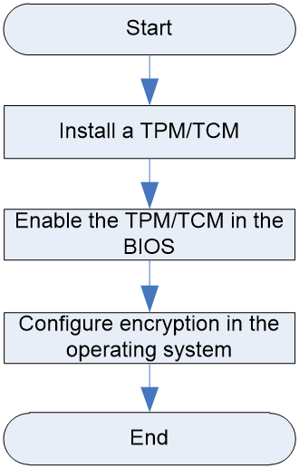
Installing a TCM or TPM
1. Remove the access panel. Press the unlock button on the access panel, slide the panel to the server rear, and lift the access panel.
2. (Optional) Remove the riser card and PCIe card that prevent you from accessing the TPM/TCM connector.
3. (Optional) Remove the storage controller that prevents you from accessing the TPM/TCM connector.
4. Install the TCM or TPM.
a. Align the TPM/TCM connector on the system board and slowly to firmly insert the TPM/TCM module downward. For the specific location of the TPM/TCM connector, see "System board."
b. Align the hole on the TPM/TCM module to insert the pin downward.
c. Insert the security rivet into the hole in the rivet pin and press the security rivet until it is firmly seated.
5. (Optional) Reinstall the removed riser card and PCIe card.
6. Install the removed riser cards, if any.
7. Install the access panel. Align the standouts on the access panel with the notches in the chassis side panels, place the panel onto the chassis, and slide the access panel to the server front until it is secured into place.
8. Install the blade server.
9. Power on the blade server. For more information, see "Powering on the blade server."
Enabling the TCM or TPM in the BIOS
1. Access the BIOS utility. For information about how to enter the BIOS utility, see the BIOS user guide.
2. Select Advanced > Trusted Computing, and press Enter.
3. Enable TCM or TPM. By default, the TCM and TPM are enabled for a server.
· If the server is installed with a TPM, perform the following actions:
a. Select TPM State > Enabled, and then press Enter.
b. Select a TPM type. Click Device Select and press Enter. After setting, press F4 to save the configuration. For more information, see the BIOS user guide for the server.
· If the TPM is installed with a TCM, perform the following actions:
a. Select TCM State > Enabled, and then press Enter.
b. Select a TCM type. Click Device Select and press Enter. After setting, press F4 to save the configuration. For more information, see the BIOS user guide for the server.
4. Log in to HDM to verify that the TCM or TPM is operating correctly. For more information, see HDM online help.
Configuring encryption in the operating system
For more information about this task, see the encryption technology feature documentation that came with the operating system.
The recovery key/password is generated during BitLocker setup, and can be saved and printed after BitLocker is enabled. When using BitLocker, always retain the recovery key/password. The recovery key/password is required to enter Recovery Mode after BitLocker detects a possible compromise of system integrity or firmware or hardware change.
For security purposes, follow these guidelines when retaining the recovery key/password:
· Always store the recovery key/password in multiple locations.
· Always store copies of the recovery key/password away from the server.
· Do not save the recovery key/password on the encrypted hard drive.
For more information about Microsoft Windows BitLocker drive encryption, visit the Microsoft website at http://technet.microsoft.com/en-us/library/cc732774.aspx.
Guidelines
· Do not remove an installed TCM or TPM. Once installed, the module becomes a permanent part of the system board.
· When installing or replacing hardware, H3C technicians cannot configure the TCM or TPM or enter the recovery key. For security reasons, only the user can perform the tasks.
· When replacing the system board, do not remove the TCM or TPM from the system board. H3C will provide a TCM or TPM with a spare system board for the replacement.
· Any attempt to remove an installed TCM or TPM from the system board breaks or disfigures the TCM or TPM security rivet. Upon locating a broken or disfigured rivet on an installed TCP or TPM, administrators should consider the system compromised and take appropriate measures to ensure the integrity of the system data.
· H3C is not liable for blocked data access caused by improper use of the TCM or TPM. For more information, see the encryption technology feature documentation provided by the operating system.
· The user cannot remove the TPM/TCM module without permission; otherwise the fixing rivet of the TPM/TCM module may be destroyed or damaged, leading to system damage.
· If you want to replace the failed TCM or TPM, remove the system board, and then contact H3C Support to replace the TCM or TPM and the system board.
Replacing the system battery
This section describes the detailed steps for replacing the system battery.
Operation scenario
The server comes with a system battery (Panasonic BR2032) installed on the system board, which supplies power to the real-time clock and has a lifespan of 3 to 5 years.
· If the server no longer automatically displays the correct date and time, you might need to replace the battery. As a best practice, use the Panasonic BR2032 battery to replace the old one.
|
|
NOTE: The BIOS will restore to the default settings after the replacement. You must reconfigure the BIOS to have the desired settings, including the system date and time. For more information, see the BIOS user guide for the server. |
Prerequisites
Take the following ESD prevention measures:
· Wear antistatic clothing.
· Wear an ESD wrist strap and make sure it makes good skin contact and is reliably grounded.
· Do not wear any conductive objects, such as jewelry or watches.
· Before installing, make sure that you back up the data, stop all services, and power off the server. For more information, see "Powering off the blade server."
· Remove the blade server.
· You might also remove other components. For the removed components to be reinstalled correctly, record their positions and connections before removal, for example, taking pictures of cable connection and drive installation positions, or labeling cables.
Removing the system battery
1. Remove the access panel. Press the unlock button on the access panel, slide the panel to the server rear, and lift the access panel.
2. (Optional) Remove the mezzanine NIC that prevents the user from contacting the system battery.
3. Remove the system battery. Pinch the system battery by its top edge and the battery will disengage from the battery holder.
|
|
NOTE: For environment protection purposes, dispose of the used-up system battery at a designated site. |
Installing the system battery
1. Install the system battery.
a. Insert the system battery with the plus sign "+" facing up into the system battery holder.
b. Press down the battery to secure it into place.
2. (Optional) If the the mezzanine NIC has been removed, install it.
3. Install the access panel. Align the standouts on the access panel with the notches in the chassis side panels, place the panel onto the chassis, and slide the access panel to the server front.
4. Install the blade server.
5. Power on the blade server. For the specific steps, see "Powering on the blade server."
6. Access the BIOS to reconfigure the system date and time. For more information, see the BIOS user guide for the server.
Replacing the system board
This section describes the detailed steps of replacing the system board.
Operation scenario
The system board fails.
Prerequisites
Take the following ESD prevention measures:
· Wear antistatic clothing.
· Wear an ESD wrist strap and make sure it makes good skin contact and is reliably grounded.
· Do not wear any conductive objects, such as jewelry or watches.
· Before replacing, make sure that you stop all services and power off the server. For more information, see "Powering off the blade server."
· Remove the blade server.
· You might also remove other components. For the removed components to be reinstalled correctly, record their positions and connections before removal, for example, taking pictures of cable connection and drive installation positions, or labeling cables.
Removing the system board
|
|
CAUTION: · To prevent electrostatic discharge, place the removed parts on an antistatic surface or in antistatic bags. · If the server is installed with a TCM/TPM, to avoid damage to the connector, do not remove the TCM/TPM. |
1. Remove all front drives.
2. Remove the access panel. Press the unlock button on the access panel, slide the panel to the server rear, and lift the access panel.
3. Remove the supercapacitor, if any.
4. Remove the air baffle.
5. Remove the front drive backplane.
6. (Optional) If the riser card and PCIe card have been installed, remove them.
7. (Optional) If the storage controller has been installed, remove it.
8. (Optional) If the straight-through card has been installed, remove it.
9. Remove all storage controllers, NVMe VROC modules, and mezzanine modules, if any.
10. Remove all DIMMs, processors, and heatsinks.
11. Install protective covers over empty processor sockets.
12. Remove the system board:
a. Loosen the two captive screws on the system board.
b. Hold the system board handle and slide the system board toward the server rear to disengage onboard connectors (for example, USB and SUV connectors) from the chassis. Then, lift the system board to remove it from the chassis.
Installing the system board
Follow the reverse order of removal to install the system board.
Replacing a drive backplane
This section describes how to replace the drive backplane.
Operation scenario
· The drive backplane fails.
· The drive backplane hinders maintenance of other parts.
Prerequisites
Take the following ESD prevention measures:
· Wear antistatic clothing.
· Wear an ESD wrist strap and make sure it makes good skin contact and is reliably grounded.
· Do not wear any conductive objects, such as jewelry or watches.
· Identify the position of the SATA M.2 SSD to be replaced.
· Identify the RAID array information of the SSD to be replaced. To replace an SSD that is not configured with a RAID or is in a non-redundancy RAID array, back up all data.
· Before replacing, make sure that you stop all services and power off the server. For more information, see "Powering off the blade server."
· Remove the blade server.
· You might also remove other components. For the removed components to be reinstalled correctly, record their positions and connections before removal, for example, taking pictures of cable connection and drive installation positions, or labeling cables.
Removing a drive backplane
1. Remove the drives attached to the backplane.
2. Remove the access panel. Press the unlock button on the access panel, slide the panel to the serve rear, and lift the access panel.
3. Remove the drive backplane. Hold the handle on the backplane to lift the backplane up.
Installing a drive backplane
1. Install a drive backplane. Align both sides of the drive backplane with the two guide slots on the drive frame to insert the drive backplane downward.
2. Install the access panel. Align the standouts on the access panel with the notches in the chassis side panels, place the panel onto the chassis, and slide the access panel to the server front until it is secured into place.
3. Install the removed drives.
4. Install the blade server. Power on the blade server. For more information, see "Powering on the blade server."
Common operations
|
|
NOTE: The software interfaces are subject to change without notice. Figures in this section are for illustration only. |
Logging in to the blade server operating system
Local login
This section describes the specific steps of local login. When performing BIOS, HDM, FIST, RAID, operating system accessing, and other operations and configurations on the server, you may need to connect the mouse, keyboard, and display terminal to complete local login of the server.
The server provides two DB15 VGA connectors for connecting the display terminal.
· The front panel provides one VGA connector.
· The rear panel provides one VGA connector.
The server does not provide the standard PS2 mouse and keyboard connectors. You can connect the mouse and keyboard through the USB connectors on the front and rear panels. Two connection methods can be adopted according to different connector types of the mouse and keyboard:
· Connect the USB mouse and keyboard directly using the connection method the same as that for the general USB cable.
· Connect the PS2 mouse and keyboard through the USB to PS2 cable.
Procedure
1. As shown in Figure 24, plug one end of the video cable into the VGA connector extended from the server SUV cable and fix it using the screws on both sides of the plug.
Figure 24 Connecting the VGA connector
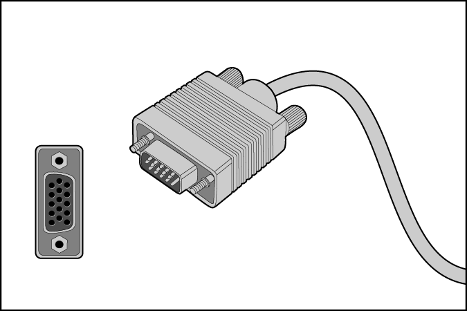
2. Plug the other end of the video cable into the VGA connector of the display terminal and fix it using the screws on both sides of the plug.
3. As shown in Figure 25, plug one end of the USB connector of the USB-PS2 cable into the USB connector extended from the server SUV cable, and connect the PS2 connectors at the other end to the mouse and keyboard respectively.
Figure 25 Connecting the USB to PS2 cable
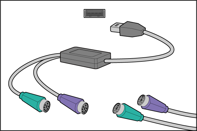
Remote login
1. Log in to OM. Enter https://OM_IP_address in the browser and press Enter. On the page that opens, enter the OM username and password, and then click Login.
Figure 26 Logging in to OM
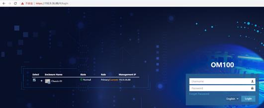
2. Log in to the blade server. As shown in Figure 27, click Compute Node Management > Corresponding Blade Server > Remote Console > KVM or H5 KVM on the OM management page.
Figure 27 Logging in to the blade server

Accessing the blade server HDM interface
1. Log in to OM. Enter https://OM IP_address in the browser and press Enter. On the page that opens, enter the OM username and password, and then click Login.
Figure 28 Logging in to OM

2. Log in to the HDM web UI. As shown in Figure 29, click Compute Node Management > Corresponding Blade Server > Remote Console > Authentication-free on the OM management page.
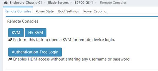
Maintenance
The following information describes the guidelines and tasks for daily server maintenance.
Guidelines
· Keep the equipment room clean and tidy. Remove unnecessary devices and objects from the equipment room.
· Make sure the temperature and humidity in the equipment room meet the server operating requirements.
· Regularly check the server from HDM or OM for operating health issues.
· Keep the operating system and software up to date as required.
· Make a reliable backup plan:
¡ Back up data regularly.
¡ If data operations on the server are frequent, back up data as needed in shorter intervals than the regular backup interval.
¡ Check the backup data regularly for data corruption.
· Stock spare components on site in case replacements are needed. After a spare component is used, prepare a new one.
· Keep the network topology up to date to facilitate network troubleshooting.
Maintenance tools
The following are major tools for server maintenance:
· Temperature and humidity meter—Monitors the operating environment of the server.
· HDM and OM—Monitor the operating status of the server.
Maintenance operation
This section describes the routine maintenance task operations and operation methods of the blade server.
Task list
Table 27 lists the routine maintenance tasks.
|
Maintenance tasks |
Maintenance tools |
|
Observing LED status |
NA |
|
Monitoring the temperature and humidity in the equipment room |
Hygrothermograph |
|
Viewing server status |
NA |
|
Collecting server logs |
NA |
|
NA |
Observing LED status
Observe the LED status on the front panels of the server to verify that the server modules are operating correctly. For more information about the status of the front panel LEDs, see "LEDs and buttons."
Monitoring the temperature and humidity in the equipment room
Use a hygrothermograph to monitor the temperature and humidity in the equipment room.
The temperature and humidity in the equipment room must meet the server requirements described in "Technical parameters."
Viewing server status
· To view the health, operating, and power states of the server, see information about status diagnoses in the OM online help.
· To view basic information and status of the subsystems of the server, see "View device information" in H3C Servers HDM Online Help.
Collecting server logs
For the procedure for collecting server logs, see collecting logs in the OM online help.
Updating firmware for the server
For the procedure for updating HDM, the BIOS, or CPLD, see the firmware upgrade guide for the server.