- Table of Contents
- Related Documents
-
| Title | Size | Download |
|---|---|---|
| 01-Text | 592.43 KB |
Contents
Logging In to the CLI Through the Serial Interface
Setting up the Hardware Environment
Accessing the CLI Through Telnet or SSH Connections
Setting up the Hardware Environment
Management Commands of Blade Enclosure
Blade Enclosure Management and Configuration Commands
display chassis subsystem-status
AE Module Management and Configuration Commands
Blade Server Management and Configuration Commands
ICM Module Management and Configuration Commands
Power Supply/Fan Configuration Command
User Management and Configuration Commands
Command Overview
Function Introduction
|
|
NOTE: · This document is applicable to H3C UniServer B16000 blade enclosure and H3C UIS 9000 appliance. The software UIs and displayed information are slightly different. This document takes H3C UniServer B16000 as an example to describe the OM module commands. · The following pairs of management commands of the OM module have the same functions and are interchangeable: undo and no, quit and exit, and display and show. For example, the display ldap-server and show ldap-server commands have the same functions. |
This manual describes device management functions supported by the OM module.
As a core management unit, the OM module interconnects with other modules inside the blade enclosure through the mid-plane to manage and monitor all modules in a centralized manner.
You can access the management software of the OM module through the serial interface, Telnet, and SSH connections to perform maintenance operations, such as query, configuration, and management, on the blade enclosure, AE module, blade server, ICM module, power supply, fan, and OM module.
This manual mainly describes the CLIs of the OM module. For details about the OM module, see the OM Module User Guide.
User Permissions
Each blade enclosure supports up to 16 different local users and 16 different LDAP groups. User permissions vary with user roles.
User permissions include user management permissions and device permissions.
· User management permissions are used to view or manage user information, such as creating a local user and modifying an LDAP group. User management permissions are determined in accordance with the user role selected when a user is created.
· Device permissions are used to view or manage devices, including the blade enclosure, OM module, AE module, blade server, ICM module, power supply, and fan. Device permissions are determined in accordance with the user role and the device to be viewed or managed.
Table 1 describes user roles and the corresponding permissions.
Table 1 User roles and permissions
|
Role |
User Management Permissions |
Device Permissions |
|
Administrator |
· It is the default administrator and a default local user. The default user name and password are admin and Password@_ respectively. · Each blade enclosure has only an administrator user, which cannot be deleted. · The administrator has the highest permissions to view and manage all user and device information, for example, creating a user, using the remote console, and setting the power redundancy mode. |
|
|
Maintainer |
It is an administrator and has the same user management permissions and device permissions as the administrator. The difference between the maintainer and the administrator is that the maintainer can be created and deleted. |
|
|
Operator |
It can view user management information and modify their passwords. |
· View information about the blade enclosure, OM module, and AE module, such as blade enclosure status and system logs. · View and manage selected device information, such as controlling the power-on status of the selected blade server and setting power limits of the blade enclosure. |
|
Viewer |
It can view user management information and modify their passwords. |
· View information about the blade enclosure, OM module, and AE module, such as blade enclosure status and system logs. · View information about the selected device, such as the port status of the selected ICM module and power system status. |
LDAP users cannot access the OM module through the CLI.
Logging In to the CLI
Logging In to the CLI Through the Serial Interface
Scenario
· When initially configuring the blade enclosure, you can connect the local client to the serial interface of the OM module and log in to the CLI of the OM module.
· If the product network is faulty or you cannot remotely access the OM module, you can connect the client to the serial interface of the OM module and log in to the CLI of the OM module for troubleshooting.
Setting up the Hardware Environment
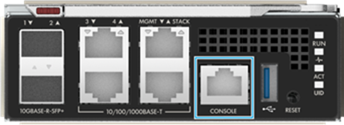
Connect the RS-232 serial interface of the PC to the Console interface of the OM module using a DB9-RJ45 cable, as shown in Figure 1.
Figure 1 Connecting the PC to the Console interface
Configuring the Client
1. Set the login parameters and log in to the OM CLI using the remote login software. Table 2_bookmark10 lists the login parameters.
|
Parameter |
Value |
|
Serial Line to connect to |
COMn, where n indicates the serial port number. The value is an integer. The specific value is subject to the actual settings. |
|
Speed (baud) |
9600 |
|
Data bits |
8 |
|
Stop bits |
1 |
|
Parity |
None |
|
Flow control |
None |
2. After login, the OM CLI displays the login page, as shown below.
******************************************************************************
Copyright (c) 2004-2019 New H3C Technologies Co., Ltd. All rights reserved.*
Without the owner's prior written consent, *
no decompiling or reverse-engineering shall be allowed. *
******************************************************************************
<OM>
Accessing the CLI Through Telnet or SSH Connections
Scenario
You can access the server from a LAN through the Telnet or SSH connections to perform remote configuration and maintenance. The OM module supports remote configurations through the Telnet or SSH connections.
Preparations
Obtain the management IP address, user name, and password of the OM module. Table 3 lists default parameters required for login through the Telnet or SSH connections.
Table 3 Parameters required for login through the Telnet or SSH connections
|
Parameter |
Value |
|
Management IP address of the OM module |
Default management IP address: 192.168.100.100/24 |
|
Port number |
· SSH: 22 · Telnet: 23 |
|
User name and password |
· Default user name: admin · Default password: Password@_ |
The SSH access mode is enabled for the OM module by default, while the Telnet access mode is disabled. If you need to access the server through the Telnet, you need to enable the Telnet access mode. For details, see the online help of the OM module.
Setting up the Hardware Environment
Connect the PC with the management (MGMT) interface of the OM module. It is recommended that the PC be connected to both active and standby OM modules, as shown in Figure 2_bookmark16.
Figure 2 Connecting the PC to the MGMT interface

Configuring the Client
Set the Telnet/SSH login parameters and log in to the OM CLI using the remote access software.
After login, the OM CLI displays the login page, as shown below.
******************************************************************************
Copyright (c) 2004-2019 New H3C Technologies Co., Ltd. All rights reserved.*
Without the owner's prior written consent, *
no decompiling or reverse-engineering shall be allowed. *
******************************************************************************
<OM>
Management Commands of Blade Enclosure
|
|
NOTE: The UIS Onboard Administrator (UOA) view is the unique view for management. All commands must be executed in this view. |
Blade Enclosure Management and Configuration Commands
access-method
Use access-method to set access methods of the OM module.
Use undo access-method to disable access methods of the OM module.
Syntax
access-method { ssh | telnet | http | ftp } *
undo access-method { ssh | telnet | http | ftp }
Default
The SSH and HTTP access methods are enabled, while both Telnet and FTP access methods are disabled.
Views
UOA view
Predefined user roles
Administrator
Maintainer
Parameters
ssh: Specifies the SSH access method. The port number is 22.
telnet: Specifies the Telnet access method. The port number is 23.
http: Specifies the HTTP access method. The port number is 80.
ftp: Specifies the FTP access method. The port number is 21.
Usage guidelines
If both SSH and Telnet are configured, you can access the OM module through both SSH and Telnet connections.
Examples
# Set the access method of the OM module to Telnet.
<OM>access-method telnet
# Set the access methods of the OM module to Telnet and SSH.
<OM>access-method telnet ssh
# Disable the SSH access method of the OM module.
<OM>undo access-method ssh
alert-mail
Use alert-mail to set the alarm email information of the blade enclosure.
Use undo alert-mail to disable the alarm email information of the blade enclosure.
Syntax
alert-mail e-mail email smtp-server smtp-server smtp-port smtp-port level level anonymous { enable | disable mail-sender mail-sender sender-name sender-name sender-password sender-password }
undo alert-mail
Default
No alarm email information exists.
Views
UOA view
Predefined user roles
Administrator
Maintainer
Parameters
email: Specifies a valid email address used to receive alarm emails. It is a string of 4 to 120 characters. You can set up to 10 email addresses of alarm email recipients, separated by semicolon (;). As a best practice, use this email address to receive only alarm information generated by the system.
smtp-server: Specifies the IPv4 address of the SMTP server.
smtp-port: Specifies the SMTP-based port number. The value ranges from 1 to 65535.
level: Specifies the level of the alarm event sent to the user by email. 1 indicates alarms and higher-level events. 2 indicates critical events. When the severity of a system event reaches the level of the alarm email, the system sends an alarm email to the specified email address.
anonymous: Specifies anonymous access. When it is set to enable, anonymous access is enabled. When it is set to disable, anonymous access is disabled.
mail-sender: Specifies a valid email address used to send alarm emails. The value is a string of 1 to 64 characters. As a best practice, use this email address to send only alarm information generated by the system. When anonymous is set to enable, this parameter is optional. If you do not specify this parameter, alarm emails are sent to the default address ([email protected]).
sender-name: Specifies the username of the alarm email sender. This parameter is mandatory when anonymous is set to disable.
sender-password: Specifies the password of the alarm email sender. This parameter is mandatory when anonymous is set to disable.
Usage guidelines
Make sure that the SMTP port number is consistent with that configured on the SMTP server.
If you repeatedly execute this command, the new configuration will overwrite the original configuration. Therefore, be cautious when you execute this command.
Examples
# Set the email address of the alarm email recipient to [email protected], IPv4 address of the SMTP server to 192.168.250.30, port number to 25, email address of the alarm email sender to [email protected], and alarm event level to 1.
<OM>alert-mail e-mail [email protected] smtp-server 192.168.250.30 smtp-port 25 level 1 anonymous enable
Related commands
alert-mail test
alert-mail test
Use alert-mail test to test the alarm email function.
Syntax
alert-mail test
Views
UOA view
Predefined user roles
Administrator
Maintainer
Usage guidelines
Before executing this command, make sure that parameters of the alert-mail command are configured correctly.
After executing this command, check whether the test email is received by the recipient. If yes, the test is successful. If not, the test fails.
Examples
# Test the alarm email function.
<OM>alert-mail test
Related commands
alert-mail
anonymous
Use anonymous to enable or disable the extended data on the Web login page.
Syntax
anonymous { disable | enable }
Default
The extended data on the Web login page is enabled.
Views
UOA view
Predefined user roles
Administrator
Maintainer
Parameters
disable: Disables the extended data. In this configuration, unauthenticated users (users do not enter the user name and passwords to log in) cannot view basic information about the OM module through the Web login page of the OM module, including the model, SN, management IP address, and status (displayed as N/A).
enable: Enables the extended data. In this configuration, unauthenticated users can view basic information about the OM module through the Web login page of the OM module.
Examples
# Disable the extended data.
<OM>anonymous disable
auto-ipv4
Use auto-ipv4 to pre-configure an IPv4 address for a slot. The address will be used as the management IPv4 address of the module installed in the slot.
Use undo auto-ipv4 to disable the pre-configured IPv4 address of a slot.
Syntax
auto-ipv4 address address mask mask gateway gateway { app app-id | blade blade-id | io io-id save { disable | enable } }
undo auto-ipv4 { app app-id | blade blade-id | io io-id }
Default
No IPv4 addresses are pre-configured for AE module, blade server, and ICM module slots.
Views
UOA view
Predefined user roles
Administrator
Maintainer
Parameters
address: Specifies a pre-configured IPv4 address.
mask: Specifies the subnet mask of the pre-configured IPv4 address. The value ranges from 255.0.0.0 to 255.255.255.254.
gateway: Specifies a pre-configured IPv4 gateway address. It must be on the same network segment as the device address.
app-id: Specifies the slot number of the AE module. The value is 1 or 2.
blade-id: Specifies the slot number of the blade server. The value ranges from 1 to 16.
io-id: Specifies the slot number of the ICM module. The value ranges from 1 to 6.
save: Saves the ICM module configuration. The value options include disable and enable.
Usage guidelines
After this command is executed on the AE module, two situations may occur:
· The AE module is not in position: After the IPv4 address is pre-configured for the AE module slot, you need to re-apply the pre-configured IPv4 address when a new AE module is inserted, to synchronize the IP information. In this case, the IPv4 address is used as the HDM management IPv4 address of the new AE module, and the previous HDM management IPv4 address becomes invalid.
· The AE module is in position: After the IPv4 address is pre-configured for the AE module slot, the IPv4 address is synchronized to the AE module and used as the new HDM management IPv4 address, while previous HDM management IPv4 address becomes invalid.
After this command is executed on the blade server, two situations may occur:
· The blade server is not in position: After the IPv4 address is pre-configured for the blade server slot, you need to re-apply the pre-configured IPv4 address when a new blade server is inserted, to synchronize the IP information. In this case, the IPv4 address is used as the HDM management IPv4 address of the new blade server, and the previous HDM management IPv4 address becomes invalid.
· The blade server is in position: After the IPv4 address is pre-configured for the blade server slot, the IPv4 address is synchronized to the blade server and used as the new HDM management IPv4 address, while previous HDM management IPv4 address becomes invalid.
After this command is executed on the ICM module, two situations may occur:
· The ICM module is not in position: After the IPv4 address is pre-configured for the ICM module slot, you need to re-apply the pre-configured IPv4 address when a new ICM module is inserted, to synchronize the IPv4 information. In this case, the IPv4 address is used as the HDM management IPv4 address of the new ICM module, and the previous HDM management IPv4 address becomes invalid.
· The ICM module is in position: After the IPv4 address is pre-configured for the ICM module slot, the IPv4 address is synchronized to the ICM module and used as the new HDM management IPv4 address, while previous HDM management IPv4 address becomes invalid. Note that the IPv4 address cannot be configured when the ICM module is in shutdown state.
Examples
# Pre-configure the IPv4 address for the AE module in slot 1, with IPv4 address set to 192.168.17.1, subnet mask to 255.255.255.0, and gateway address to 192.168.17.254.
<OM>auto-ipv4 address 192.168.17.1 mask 255.255.255.0 gateway 193.168.17.254 app 1
# Pre-configure the IPv4 address for the blade server in slot 1, with IPv4 address set to 192.168.10.1, subnet mask to 255.255.255.0, and gateway address to 193.168.10.254.
<OM>auto-ipv4 address 192.168.10.1 mask 255.255.255.0 gateway 193.168.10.254 blade 1
# Pre-configure the IPv4 address for the ICM module in slot 1, with IPv4 address set to 192.168.20.1, subnet mask to 255.255.255.0, and gateway address to 192.168.20.254. Enable the configuration saving function.
<OM>auto-ipv4 address 192.168.20.1 mask 255.255.255.0 gateway 192.168.20.254 io 1 save enable
Syntax
display auto-ipv4 app
display auto-ipv4 blade
display auto-ipv4 io
auto-ipv6
Use auto-ipv6 to pre-configure the IPv6 address for the slot, used as the management IPv6 address of the module inserted in the slot.
Use undo auto-ipv6 to disable the pre-configured IPv6 address of a slot.
Syntax
auto-ipv6 address address prefix gateway gateway { app app-id | blade blade-id | io io-id save { disable | enable } }
undo auto-ipv6 { app app-id | blade blade-id | io io-id }
Default
No IPv6 addresses are pre-configured for the AE module, blade server, and ICM module slots.
Views
UOA view
Predefined user roles
Administrator
Maintainer
Parameters
address: Specifies a pre-configured IPv6 address.
prefix: Specifies the network prefix length of the pre-configured IPv6 address. The value ranges from 1 to 127.
gateway: Specifies a pre-configured IPv6 gateway address of the AE module, blade server, or ICM module.
app-id: Specifies the slot number of the AE module. The value is 1 or 2.
blade-id: Specifies the slot number of the blade server. The value ranges from 1 to 16.
io-id: Specifies the slot number of the ICM module. The value ranges from 1 to 6.
save { disable | enable }: Saves the ICM module configuration.
Usage guidelines
After this command is executed on the AE module, two situations may occur:
· The AE module is not in position: After the IPv6 address is pre-configured for the AE module slot, you need to re-apply the pre-configured IPv6 address when a new AE module is inserted, to synchronize the IP information. In this case, the IPv6 address is used as the HDM management IPv6 address of the new AE module, and the previous HDM management IPv6 address becomes invalid.
· The AE module is in position: After the IPv6 address is pre-configured for the AE module slot, the IPv6 address is synchronized to the AE module and used as the new HDM management IPv6 address, while previous HDM management IPv6 address becomes invalid.
After this command is executed on the blade server, two situations may occur:
· The blade server is not in position: After the IPv6 address is pre-configured for the blade server slot, you need to re-apply the pre-configured IPv6 address when a new blade server is inserted, to synchronize the IP information. In this case, the IPv6 address is used as the HDM management IPv6 address of the new blade server, and the previous HDM management IPv6 address becomes invalid.
· The blade server is in position: After the IPv6 address is pre-configured for the blade server slot, the IPv6 address is synchronized to the blade server and used as the new HDM management IPv6 address, while previous HDM management IPv6 address becomes invalid.
After this command is executed on the ICM module, two situations may occur:
· The ICM module is not in position: After the IPv6 address is pre-configured for the ICM module slot, you need to re-apply the pre-configured IPv6 address when a new ICM module is inserted, to synchronize the IPv6 information. In this case, the IPv6 address is used as the HDM management IPv6 address of the new ICM module, and the previous HDM management IPv6 address becomes invalid.
· The ICM module is in position: After the IPv6 address is pre-configured for the ICM module slot, the IPv6 address is synchronized to the ICM module and used as the new HDM management IPv6 address, while previous HDM management IPv6 address becomes invalid. Note that the IPv6 address cannot be configured when the ICM module is in shutdown state.
Examples
# Pre-configure the IPv6 address for the AE module in slot 1, with IPv6 address set to 2001:0410::45FF, network prefix length to 12, and gateway address to 2001:0410::1.
<OM>auto-ipv6 address 2001:0410::45FF 12 gateway 2001:0410::1 app 1
# Pre-configure the IPv6 address for the blade server in slot 1, with IPv6 address set to 2001:0510::45FF, network prefix length to 12, and gateway address to 2001:0510::1.
<OM>auto-ipv6 address 2001:0510::45FF 12 gateway 2001:0510::1 blade 1
# Pre-configure the IPv6 address for the ICM module in slot 1, with IPv6 address set to 2001:0610::45FF, network prefix length to 12, and gateway address to 2001:0610::1. Enable the configuration saving function.
<OM>auto-ipv6 address 2001:0610::45FF 12 gateway 2001:0610::1 io 1 save enable
Syntax
display auto-ipv6 app
display auto-ipv6 blade
display auto-ipv6 io
chassis asset-label
Use chassis asset-label to set the asset label of the blade enclosure.
Syntax
chassis asset-label asset-label
Default
The asset label is not set.
Views
UOA view
Predefined user roles
Administrator
Maintainer
Parameters
asset-label: Specifies the asset label of the blade enclosure. It is a case-sensitive string of 1 to 32 characters.
Examples
# Set the asset label to 123456789.
<OM>chassis asset-label 123456789
Syntax
display chassis basic
chassis location
Use chassis location to set the location of the blade enclosure.
Syntax
chassis location location
Default
The location of the blade enclosure is Hangzhou.
Views
UOA view
Predefined user roles
Administrator
Maintainer
Parameters
location: Specifies the location of the blade enclosure. It is a case-sensitive string of 1 to 20 characters.
Examples
# Set the location of the blade enclosure to shanghai.
<OM>chassis location shanghai
Syntax
display chassis basic
chassis name
Use chassis name to set the name of the blade enclosure.
Syntax
chassis name name
Default
The name of the blade enclosure is Chassis-01.
Views
UOA view
Predefined user roles
Administrator
Maintainer
Parameters
name: Indicates the name of the blade enclosure. It is a case-sensitive string of 1 to 20 characters.
Examples
# Set the name of the blade enclosure to server.
<OM>chassis name server
clock
Use clock to set the date and time of the blade enclosure.
Syntax
clock { date date time time | ntp server-ip ip-address }
Default
The system time is not set.
Views
UOA view
Predefined user roles
Administrator
Maintainer
Parameters
date date: Specifies the date, in the format of YYYY/MM/DD.
time time: Specifies the time, in the format of HH:MM:SS.
server-ip ip-address: Specifies the IP address of the NTP server.
Usage guidelines
In the OM module, system logs and error and fault handling are recorded based on system date and time. You can correctly set the time and date in the following ways:
· Run the clock date date time time command to directly specify the system date and time.
· Run the clock ntp server-ip ip-address command to specify the IP address of the Network Time Protocol (NTP) server. The system time will be synchronized with the NTP server.
|
|
NOTE: If the updated time is earlier than the current time, the system may delete partial or all history power information. |
Examples
# Set the time of the blade enclosure to 14:25:00 on July 27, 2017.
<OM>clock date 2017/7/27 time 14:25:00
Related commands
display chassis time
display auto-ipv4
Use display auto-ipv4 to display the pre-configured IPv4 addresses of all slots that accommodate AE modules, blade servers, or ICM modules.
Syntax
display auto-ipv4 { app | blade | io }
Views
UOA view
Predefined user roles
Administrator
Maintainer
Operator
Viewer
Examples
# Display the IPv4 addresses of all slots that accommodate AE modules.
<OM>display auto-ipv4 app
App Status Present Auto-IP Auto-Mask Auto-Gateway Current-
IP
1 Disabled True 0.0.0.0 0.0.0.0 0.0.0.0 192.103.
4.15
2 Disabled True 0.0.0.0 0.0.0.0 0.0.0.0 192.103.
4.201
Table 4 Command output
|
Field |
Description |
|
App |
Slot number of the AE module |
|
Status |
· Enabled: The pre-configured IPv4 address of the slot that accommodates the AE module is enabled. · Disabled: The pre-configured IPv4 address of the slot that accommodates the AE module is disabled. |
|
Present |
Whether the AE module is in position · True: in position · False: not in position |
|
Auto-IP |
Pre-configured IPv4 address |
|
Auto-Mask |
Subnet mask of the pre-configured IPv4 address |
|
Auto-Gateway |
Pre-configured IPv4 gateway address |
|
Current-IP |
IPv4 address of the HDM of the AE module. You can determine whether the pre-configured IPv4 address takes effect on the AE module by checking whether the values of Auto-IP and Current-IP are consistent. |
# Display the pre-configured IPv4 addresses for all slots that accommodate the blade servers.
<OM>display auto-ipv4 blade
Blade Status Present Auto-IP Auto-Mask Auto-Gateway Current-
IP
1 Disabled True 0.0.0.0 0.0.0.0 0.0.0.0
2 Enabled True 111.222.111.222 255.255.0.0 111.111.111.111 111.222.
111.222
3 Disabled True 0.0.0.0 0.0.0.0 0.0.0.0
4 Disabled True 0.0.0.0 0.0.0.0 0.0.0.0
5 Disabled True 0.0.0.0 0.0.0.0 0.0.0.0
6 Disabled True 0.0.0.0 0.0.0.0 0.0.0.0
7 Disabled True 0.0.0.0 0.0.0.0 0.0.0.0
8 Disabled True 0.0.0.0 0.0.0.0 0.0.0.0
9 Disabled True 0.0.0.0 0.0.0.0 0.0.0.0
10 Disabled True 0.0.0.0 0.0.0.0 0.0.0.0 192.101.
4.69
11 Disabled True 0.0.0.0 0.0.0.0 0.0.0.0
12 Disabled True 0.0.0.0 0.0.0.0 0.0.0.0
13 Disabled True 0.0.0.0 0.0.0.0 0.0.0.0
14 Disabled True 0.0.0.0 0.0.0.0 0.0.0.0
15 Disabled True 0.0.0.0 0.0.0.0 0.0.0.0
16 Disabled True 0.0.0.0 0.0.0.0 0.0.0.0
Table 5 Command output
|
Field |
Description |
|
Blade |
Slot number of the blade server |
|
Status |
· Enabled: The pre-configured IPv4 address of the slot that accommodates the blade server is enabled. · Disabled: The pre-configured IPv4 address of the slot that accommodates the blade server is disabled. |
|
Present |
Whether the blade server is in position · True: in position · False: not in position |
|
Auto-IP |
Pre-configured IPv4 address |
|
Auto-Mask |
Subnet mask of the pre-configured IPv4 address |
|
Auto-Gateway |
Pre-configured IPv4 gateway address |
|
Current-IP |
IPv4 address of the HDM of the blade server. You can determine whether the pre-configured IPv4 address takes effect on the blade server by checking whether the values of Auto-IP and Current-IP are consistent. |
# Display the pre-configured IPv4 addresses for all slots that accommodate the ICM modules.
<OM>display auto-ipv4 io
IO Status Present Auto-IP Auto-Mask Auto-Gateway Current-
IP
1 Enabled True 192.168.20.1 255.255.255.0 192.168.20.254 192.168.
20.1
2 Enabled True 192.168.48.2 255.0.0.0 0.0.0.0 0.0.0.0
3 Enabled True 192.168.48.3 255.0.0.0 0.0.0.0 0.0.0.0
4 Disabled True 0.0.0.0 0.0.0.0 0.0.0.0
5 Enabled True 192.168.48.5 255.0.0.0 0.0.0.0 0.0.0.0
6 Enabled True 192.168.48.6 255.0.0.0 0.0.0.0 0.0.0.0
Table 6 Command output
|
Field |
Description |
|
IO |
Slot number of the ICM module |
|
Status |
· Enabled: The pre-configured IPv4 address of the slot that accommodates the ICM module is enabled. · Disabled: The pre-configured IPv4 address of the slot that accommodates the ICM module is disabled. |
|
Present |
Whether the ICM module is in position · True: in position · False: not in position |
|
Auto-IP |
Pre-configured IPv4 address |
|
Auto-Mask |
Subnet mask of the pre-configured IPv4 address |
|
Auto-Gateway |
Pre-configured IPv4 gateway address |
|
Current-IP |
Management IPv4 address of the ICM module in the slot. You can determine whether the pre-configured IPv4 address takes effect on the ICM module by checking whether the values of Auto-IP and Current-IP are consistent. |
display auto-ipv6
Use display auto-ipv6 to display the pre-configured IPv6 addresses of all slots that accommodate AE modules, blade servers, or ICM modules.
Syntax
display auto-ipv6 { app | blade | io }
Views
UOA view
Predefined user roles
Administrator
Maintainer
Operator
Viewer
Examples
# Display the IPv6 addresses of all slots that accommodate AE modules.
<OM>display auto-ipv6 app
App : 1
Status : Enabled
Present : True
Auto-IP : 2001:410:0:1::45FF/12
Current-IP : 2001:410:0:1::45ff
App : 2
Status : Enabled
Present : True
Auto-IP : 2001:410:0:1::46FF/12
Current-IP : 2001:410:0:1::46FF
Table 7 Command output
|
Field |
Description |
|
App |
Slot number of the AE module |
|
Status |
· Enabled: The pre-configured IPv6 address of the slot that accommodates the AE module is enabled. · Disabled: The pre-configured IPv6 address of the slot that accommodates the AE module is disabled. |
|
Present |
Whether the AE module is in position · True: in position · False: not in position |
|
Auto-IP |
Pre-configured IPv6 address and network prefix |
|
Current-IP |
IPv6 address and network prefix of the HDM of the AE module. You can determine whether the pre-configured IPv6 address takes effect on the AE module by checking whether the values of Auto-IP and Current-IP are consistent. |
# Display the pre-configured IPv6 addresses for all slots that accommodate the blade servers.
<OM>display auto-ipv6 blade
Blade : 1
Status : Enabled
Present : True
Auto-IP : 66::45F2/16
Current-IP : 66::45F2/16
Blade : 2
Status : Enabled
Present : True
Auto-IP : 66::45F3/16
Current-IP : 66::45F3/16
Blade : 3
Status : Enabled
Present : True
Auto-IP : 1::1/45
Current-IP : :
Blade : 4
Status : Disabled
Present : True
Auto-IP : ::/0
Current-IP : :
Blade : 5
Status : Disabled
Present : True
Auto-IP : ::/0
Current-IP : :
Blade : 6
Status : Enabled
Present : True
Auto-IP : 66::45F7/16
Current-IP : :
Blade : 7
Status : Disabled
Present : True
Auto-IP : ::/0
Current-IP : :
Blade : 8
Status : Disabled
Present : True
Auto-IP : ::/0
Current-IP : :
Blade : 9
Status : Disabled
Present : True
Auto-IP : ::/0
Current-IP : :
Blade : 10
Status : Disabled
Present : True
Auto-IP : ::/0
Current-IP : :
Blade : 11
Status : Disabled
Present : True
Auto-IP : ::/0
Current-IP : :
Blade : 12
Status : Disabled
Present : True
Auto-IP : ::/0
Current-IP : :
Blade : 13
Status : Disabled
Present : True
Auto-IP : ::/0
Current-IP : :
Blade : 14
Status : Disabled
Present : True
Auto-IP : ::/0
Current-IP : :
Blade : 15
Status : Disabled
Present : True
Auto-IP : ::/0
Current-IP : :
Blade : 16
Status : Disabled
Present : True
Auto-IP : ::/0
Current-IP : :
Table 8 Command output
|
Field |
Description |
|
Blade |
Slot number of the blade server |
|
Status |
· Enabled: The pre-configured IPv6 address of the slot that accommodates the blade server is enabled. · Disabled: The pre-configured IPv6 address of the slot that accommodates the blade server is disabled. |
|
Present |
Whether the blade server is in position · True: in position · False: not in position |
|
Auto-IP |
Pre-configured IPv6 address and network prefix |
|
Current-IP |
IPv6 address and network prefix of the HDM of the blade server. You can determine whether the pre-configured IPv6 address takes effect on the blade server by checking whether the values of Auto-IP and Current-IP are consistent. |
# Display the pre-configured IPv6 addresses for all slots that accommodate the ICM modules.
<OM>display auto-ipv6 io
IO : 1
Status : Disabled
Present : True
Auto-IP : ::/0
Auto-Gateway : ::
Current-IP : ::
IO : 2
Status : Disabled
Present : True
Auto-IP : ::/0
Auto-Gateway : ::
Current-IP : ::
IO : 3
Status : Disabled
Present : True
Auto-IP : ::/0
Auto-Gateway : ::
Current-IP : ::
IO : 4
Status : Disabled
Present : True
Auto-IP : ::/0
Auto-Gateway : ::
Current-IP : ::
IO : 5
Status : Disabled
Present : True
Auto-IP : ::/0
Auto-Gateway : ::
Current-IP : ::
IO : 6
Status : Enabled
Present : True
Auto-IP : 55::45F7/16
Auto-Gateway : 55::45F9/16
Current-IP : ::
Table 9 Command output
|
Field |
Description |
|
IO |
Slot number of the ICM module |
|
Status |
· Enabled: The pre-configured IPv6 address of the slot that accommodates the ICM module is enabled. · Disabled: The pre-configured IPv6 address of the slot that accommodates the ICM module is disabled. |
|
Present |
Whether the ICM module is in position · True: in position · False: not in position |
|
Auto-IP |
Pre-configured IPv6 address and network prefix |
|
Auto-Gateway |
Pre-configured IPv6 gateway address |
|
Current-IP |
Management IPv6 address and network prefix of the ICM module in the slot. You can determine whether the pre-configured IPv6 address takes effect on the ICM module by checking whether the values of Auto-IP and Current-IP are consistent. |
display power-delay
Use display power-delay to display power-on delay configuration of all AE modules or blade servers.
Syntax
display power-delay { app | blade }
Views
UOA view
Predefined user roles
Administrator
Maintainer
Operator
Viewer
Parameters
app: Displays the power-on delay configuration of all AE modules.
blade: Displays the power-on delay configuration of all blade servers.
Examples
# Display the power-on delay configuration of all AE modules.
<OM>display power-delay app
Slot Name Status Delay Second
1 AE100-1 Enable 1500
2 AE100-2 Disable 0
Table 10 Command output
|
Field |
Description |
|
Slot |
Slot number of the AE module or blade server |
|
Name |
Name of the AE module or blade server |
|
Status |
· Enable: The power-on delay function is enabled for the AE module or blade server. · Disable: The power-on delay function is not enabled for the AE module or blade server. |
|
Delay Second |
Delay period, in the unit of seconds |
power-delay disable
Use power-delay disable to disable the power-on delay function for an AE module or a blade server in the specified slot.
Syntax
power-delay disable { app app-id | blade blade-id }
Views
UOA view
Predefined user roles
Administrator
Maintainer
Parameters
app app-id: Disables the power-on delay function for an AE module in the specified slot. The value is 1 or 2.
blade blade-id: Disables the power-on delay function for a blade server in the specified slot. The value ranges from 1 to 16.
Usage guidelines
Disable the power-on delay function for AE module or blade server slots.
Examples
# Disable the power-on delay function for the AE module in slot 1.
<OM>power-delay disable app 1
power-delay poweron
Use power-delay poweron to enable power-on delay for an AE module or a blade server in the specified slot.
Syntax
power-delay poweron second delay-second { app app-id | blade blade-id }
Views
UOA view
Predefined user roles
Administrator
Maintainer
Parameters
second delay-second: Specifies the delay time in seconds. The value ranges from 1 to 3600.
app app-id: Enable power-on delay for an AE module in the specified slot. The value is 1 or 2.
blade blade-id: Enable power-on delay for a blade server in the specified slot. The value ranges from 1 to 16.
Examples
# Enable power-on delay for the AE module in slot 1 and set the system to automatically power on the AE module in 1200s after the whole system is restarted.
<OM>power-delay poweron second 1200 app 1
display chassis access-method
Use display chassis access-method to display the access mode of the OM module.
Syntax
display chassis access-method
Views
UOA view
Predefined user roles
Administrator
Maintainer
Operator
Viewer
Examples
# Display the access mode of the OM module.
<OM>display chassis access-method
Access methods:
HTTPS
Telnet
Anonymous: Enabled
Table 11 Command output
|
Field |
Description |
|
Access methods |
Access method of the OM module: · HTTPS · SSH · Telnet · HTTP · FTP |
|
Anonymous |
Enable or disable (the anonymous command) the extended data on the Web login page. The value options include: · Enabled · Disabled |
display chassis alert-mail
Use display chassis alert-mail to display the alarm email settings of the blade enclosure.
Syntax
display chassis alert-mail
Views
UOA view
Predefined user roles
Administrator
Maintainer
Operator
Viewer
Examples
# Display the alarm email settings of the blade enclosure.
<OM>display chassis alert-mail
Email notification : Enabled
SMTP server : 2.3.32.3
SMTP port : 88
Email address : [email protected]
Sender address : [email protected]
Severity level : Warning
Table 12 Command output
|
Field |
Description |
|
Email notification |
Status of the alarm email function. The value options include: · Enabled: Enable the alarm email function. · Disabled: Disable the alarm email function. |
|
SMTP server |
SMTP server address |
|
SMTP port |
Port number of the SMTP server |
|
Email address |
Email address used to receive alarm emails |
|
Sender address |
Email address used to send alarm emails |
|
Severity level |
Alarm event level · Warning: When an alarm or a higher-level event occurs, the system sends an alarm email to the specified email address. · Emergency: When a critical event occurs, the system sends an alarm email to the specified email address. |
display chassis basic
Use display chassis basic to display basic information about the blade enclosure.
Syntax
display chassis basic
Views
UOA view
Predefined user roles
Administrator
Maintainer
Operator
Viewer
Examples
# Display basic information about the blade enclosure.
<OM>display chassis basic
Name : Chassis-01
Location : ShangHai
Asset label : fff
Table 13 Command output
|
Field |
Description |
|
Name |
Name of the blade enclosure |
|
Location |
Physical location of the blade enclosure |
|
Asset label |
Asset label of the blade enclosure |
display chassis subsystem-status
Use display chassis subsystem-status to display the status of the blade enclosure subsystem.
Syntax
display chassis subsystem-status
Views
UOA view
Predefined user roles
Administrator
Maintainer
Operator
Viewer
Usage guidelines
The blade enclosure subsystem includes the blade server, AE module, ICM module, power module, and fan module.
Examples
# Display the status of the blade enclosure subsystem.
<OM>display chassis subsystem-status
APP status:
APP1 : Abnormal
APP2 : Normal
Blade status:
Blade10 : Abnormal
IO status:
IO4 : Normal
PSU status:
PSU4 : Normal
Fan status:
Fan5 : Normal
Fan6 : Normal
Fan9 : Over temperature
Fan10 : Normal
Fan11 : Over temperature
Fan12 : Normal
Table 14 Command output
|
Field |
Description |
|
APP status |
Status of the AE module · Normal · Warning · Downgrade · Abnormal · Unknown · Initializing · Updating |
|
Blade status |
Status of the blade server · Normal · Warning · Downgrade · Abnormal · Unknown · Initializing · Updating |
|
IO status |
Status of the ICM module · Normal · Warning · Abnormal |
|
PSU status |
Running status of the power module · Normal · Output overvoltage fault · Output overvoltage warning · Output undervoltage fault · Output undervoltage warning · Input overvoltage fault · Input overvoltage warning · Input undervoltage fault · Input undervoltage warning · Input low voltage warning · Output overcurrent fault · Output overcurrent warning · Overtemperature fault · Overtemperature warning · PSU-fan1 fault · PSU-fan2 fault · PSU-fan1 warning · PSU-fan2 warning · PSU-fan1 overspeed · PSU-fan2 overspeed · PSU no input · Connect fault · PSU updating |
|
Fan status |
Fan status: · Normal · Overtemperature · Stopped: stopped rotating · Abnormal: communication error · Updating · Init: loading |
display chassis time
Use display chassis time to display the time and date of the blade enclosure.
Syntax
display chassis time
Views
UOA view
Predefined user roles
Administrator
Maintainer
Operator
Viewer
Examples
# Display the time and date of the blade enclosure.
<OM>display chassis time
Date : 2017/03/18
Time : 14:29:44
NTP : Enabled
NTP Server : 192.168.50.31
Table 15 Command output
|
Field |
Description |
|
Date |
System date |
|
Time |
System time |
|
NTP |
NTP service status: · Enabled · Disabled |
|
NTP server |
IP address of the NTP server |
display chassis vlan-policy
Use display chassis vlan-policy to display the VLAN policy of the blade enclosure.
Syntax
display chassis vlan-policy
Views
UOA view
Predefined user roles
Administrator
Maintainer
Operator
Viewer
Examples
# Display the VLAN policy of the blade enclosure.
<OM>display chassis vlan-policy
VLAN policy ID : 0
Policy name : Default.
PVID : 1
VLANs :
Used : False
VLAN policy ID : 1
Policy name : abc
PVID : 10
VLANs : 10
Used : False
VLAN policy ID : 2
Policy name : 2030
PVID : 20
VLANs : 20-30
Used : True
Table 16 Command output
|
Field |
Description |
|
VLAN policy ID |
VLAN policy ID. It is a unique identifier of the policy. When the VLAN policy ID is set to 0, the policy is the default VLAN policy, and its PVID is 1, indicating that no VLAN is configured for the port to pass through. |
|
Policy name |
Custom VLAN policy name. The default VLAN policy is named Default. |
|
PVID |
PVID of the port to which the VLAN policy is assigned |
|
VLANs |
All VLANs that allow the port to pass through based on the assigned VLAN policy |
|
Used |
Whether the VLAN policy is applied to the external service interface of the OM module. The default VLAN policy (Default.) is always displayed as False. |
display frame
Use display frame to display hardware information of the blade enclosure.
Syntax
display frame
Views
UOA view
Predefined user roles
Administrator
Maintainer
Operator
Viewer
Examples
# Display hardware information of the blade enclosure.
<OM>display frame
Manufacturer : H3C
Product name : B16000
Serial number : 2102-35A1-Q700-0001
Table 17 Command output
|
Field |
Description |
|
Manufacturer |
Manufacturer |
|
Product name |
Device name |
|
Serial number |
SN |
display manager
Use display manager to display information about all in-position OM modules.
Syntax
display manager
Views
UOA view
Predefined user roles
Administrator
Maintainer
Operator
Viewer
Examples
# Display information about all in-position OM modules.
<OM>display manager
ID 1:
Type : Standby
Manufacturer : H3C
Product name : OM100
Serial number : 0303KKFF
Firmware version :
Running status : Normal
UID LED : Off
CPU usage : 43%
ID 2:
Type : Active
Manufacturer : H3C
Product name : OM100
Serial number : 0303AABB
Firmware version : H3C OM100-1.00.09
Running status : Normal
UID LED : Off
CPU usage : 43%
Table 18 Command output
|
Field |
Description |
|
ID |
Slot number of the OM module |
|
Type |
Type of the OM module · Active · Standby |
|
Manufacturer |
Manufacturer |
|
Product name |
Product name |
|
Serial number |
SN |
|
Firmware version |
Firmware version |
|
Running status |
Running status of the OM module: · Normal · Warning · Abnormal |
|
UID LED |
Status of the UID LED · Off · On |
|
CPU usage |
CPU usage |
display manager firmware
Use display manager firmware to display firmware information of all in-position OM modules.
Syntax
display manager firmware
Views
UOA view
Predefined user roles
Administrator
Maintainer
Operator
Viewer
Examples
# Display firmware information of all in-position OM modules.
<OM>display manager firmware
Manager ID Manager name Firmware version
1 OM100 H3C OM100-1.00.04
2 OM100
Table 19 Command output
|
Field |
Description |
|
Manager ID |
Slot number of the OM module |
|
Manager name |
Name of the OM module |
|
Firmware version |
Firmware version of the OM module |
display manager ipconfig
Use display manager ipconfig to display network information of the OM module.
Syntax
display manager ipconfig
Views
UOA view
Predefined user roles
Administrator
Maintainer
Operator
Viewer
Usage guidelines
If the IPv6 function is not enabled for the management IP address of the OM module, the values of all IPv6 parameters are displayed as N/A.
Examples
# Display network information of the OM module.
<OM>display manager ipconfig
IPv4 configuration:
IP address : 192.168.250.30
Mask : 255.255.0.0
MAC address : 00-E0-FC-00-3C-04
Gateway : 192.168.250.1
IPV6 configuration :
IP address : 500::18
Prefix length: 64
Gateway : 500::1
Table 20 Command output
|
Field |
Description |
|
IPv4 configuration |
IPv4 address information of the OM module |
|
IP address |
IPv4 address of the OM module |
|
Mask |
Mask information of the OM module |
|
MAC address |
MAC address of the OM module |
|
Gateway |
Gateway address of the OM module |
|
IPv6 configuration |
IPv6 address information of the OM module |
|
IP address |
IPv6 address of the OM module |
|
Prefix length |
Network prefix length of the IPv6 address configured for the OM module |
|
Gateway |
Gateway address of the OM module |
display manager port
Use display manager port to display port information of the specified OM module.
Syntax
display manager port manager manager-id
Views
UOA view
Predefined user roles
Administrator
Maintainer
Operator
Viewer
Parameters
manager-id: Specifies the slot number of the OM module. The value is 1 or 2.
Usage guidelines
The internal interface of the OM module indicates the interface used by the OM module to interconnect with the blade server or AE module. Table 21 lists the mapping between internal interfaces and blade servers or AE modules.
Table 21 Mapping of internal interfaces
|
Slot of Blade Server or AE Module |
Port ID of Internal Interface |
Internal Interface Name |
|
Slots of blade servers |
||
|
Slot 1 |
Port 6 |
GigabitEthernet1/0/6 |
|
Slot 2 |
Port 7 |
GigabitEthernet1/0/7 |
|
Slot 3 |
Port 8 |
GigabitEthernet1/0/8 |
|
Slot 4 |
Port 9 |
GigabitEthernet1/0/9 |
|
Slot 5 |
Port 10 |
GigabitEthernet1/0/10 |
|
Slot 6 |
Port 11 |
GigabitEthernet1/0/11 |
|
Slot 7 |
Port 12 |
GigabitEthernet1/0/12 |
|
Slot 8 |
Port 13 |
GigabitEthernet1/0/13 |
|
Slot 9 |
Port 14 |
GigabitEthernet1/0/14 |
|
Slot 10 |
Port 15 |
GigabitEthernet1/0/15 |
|
Slot 11 |
Port 16 |
GigabitEthernet1/0/16 |
|
Slot 12 |
Port 17 |
GigabitEthernet1/0/17 |
|
Slot 13 |
Port 18 |
GigabitEthernet1/0/18 |
|
Slot 14 |
Port 19 |
GigabitEthernet1/0/19 |
|
Slot 15 |
Port 20 |
GigabitEthernet1/0/20 |
|
Slot 16 |
Port 21 |
GigabitEthernet1/0/21 |
|
Slots of AE modules |
||
|
E1 |
Port 22 |
GigabitEthernet1/0/28 |
|
E2 |
Port 23 |
GigabitEthernet1/0/29 |
Examples
# Display port information of the OM module in slot 1.
<OM>display manager port manager 1
Port ID Name Type
0 Vlan-interface4094 Management
1 Ten-GigabitEthernet1/0/1 Service
2 Ten-GigabitEthernet1/0/2 Service
3 GigabitEthernet1/0/3 Service
4 GigabitEthernet1/0/4 Service
5 GigabitEthernet1/0/5 Cascade
6 GigabitEthernet1/0/6 Internal
7 GigabitEthernet1/0/7 Internal
8 GigabitEthernet1/0/8 Internal
9 GigabitEthernet1/0/9 Internal
10 GigabitEthernet1/0/10 Internal
11 GigabitEthernet1/0/11 Internal
12 GigabitEthernet1/0/12 Internal
13 GigabitEthernet1/0/13 Internal
14 GigabitEthernet1/0/14 Internal
15 GigabitEthernet1/0/15 Internal
16 GigabitEthernet1/0/16 Internal
17 GigabitEthernet1/0/17 Internal
18 GigabitEthernet1/0/18 Internal
19 GigabitEthernet1/0/19 Internal
20 GigabitEthernet1/0/20 Internal
21 GigabitEthernet1/0/21 Internal
22 GigabitEthernet1/0/28 Internal
23 GigabitEthernet1/0/29 Internal
Table 22 Command output
|
Field |
Description |
|
Port ID |
Port ID of the OM module |
|
Name |
Port name of the OM module |
|
Type |
Port type: · Management · Service · Internal: internal interface used to interconnect with the blade server or AE module · Cascade |
display manager vlan
Use display manager vlan to display the VLAN and MAC information of the port of the specified OM module.
Syntax
display manager vlan manager manager-id port port-id
Views
UOA view
Predefined user roles
Administrator
Maintainer
Operator
Viewer
Parameters
manager-id: Specifies the slot number of an OM module. The value is 1 or 2.
port-id: Specifies the port number of an OM module. The value ranges from 0 to 23.
Examples
# Display the VLAN and MAC information of port 1 of the OM module in slot 1.
<OM>display manager vlan manager 1 port 1
MAC address : 00-E0-FC-00-3C-29
VLAN PVID : 3232
VLAN policy members : 2323-4043
Table 23 Command output
|
Field |
Description |
|
MAC address |
MAC address of the port of the OM module |
|
VLAN PVID |
PVID of the port. The default value is 1. After a VLAN policy is applied, it is set to the PVID specified in the VLAN policy. |
|
VLAN policy members |
Group of VLANs that allow the port to pass through. The default value is 1. After a VLAN policy is applied, it is set to the VLAN member specified in the VLAN policy. |
manager firmware-update
Use manager firmware-update to update the firmware of the OM module.
Syntax
manager firmware-update name
Views
UOA view
Predefined user roles
Administrator
Maintainer
Parameters
name: Specifies the firmware installation package to be updated.
Usage guidelines
Before running this command, place the firmware installation package used for update in the flash directory of the OM module. After you run this command, the OM module automatically completes the update.
Examples
# Update the firmware of the OM module using installation package uis.ipe.
<OM>manager firmware-update uis.ipe
Related commands
display manager firmware
manager ipv4
Use manager ipv4 to set the IPv4 address information of the OM module.
Syntax
manager ipv4 address address mask mask gateway gateway
Default
The IPv4 address of the OM module is 192.168.100.100/24.
Views
UOA view
Predefined user roles
Administrator
Maintainer
Parameters
address: Specifies the IPv4 address configured for the management interface of the OM module.
mask: Specifies the mask configured for the management interface of the OM module.
gateway: Specifies the gateway address configured for the management interface of the OM module.
Usage guidelines
If the IPv4 address information of the management interface of the OM module is changed, the current connections of the OM module may be interrupted. Therefore, after running this command, you must log in to the OM module again with the new IPv4 address.
Examples
# Set the IPv4 address to 192.168.250.30, mask to 255.255.0.0, and gateway address to 192.168.245.26 for the management port of the OM module.
<OM>manager ipv4 address 192.168.250.30 mask 255.255.0.0 gateway 192.168.245.26
manager ipv6
Use manager ipv6 to set the IPv6 address information of the OM module.
Use undo manager ipv6 to disable the IPv6 function of the OM module.
Syntax
manager ipv6 address address prefix gateway gateway
undo manager ipv6
Default
The IPv6 function is disabled.
Views
UOA view
Predefined user roles
Administrator
Maintainer
Parameters
address: Specifies the IPv6 address configured for the management interface of the OM module.
prefix: Specifies the network prefix length of the IPv6 address configured for the management interface of the OM module. The value ranges from 1 to 127.
gateway: Specifies the IPv6 gateway address configured for the management interface of the OM module.
Examples
# Set the IPv6 address to 2001::45FF 64, network prefix length to 64, and gateway address to 2001::4555 for the management port of the OM module.
<OM>manager ipv6 address 2001::45FF 64 gateway 2001::4555
# Disable the IPv6 function of the OM module.
<OM>undo manager ipv6
sol connect
Use sol connect to redirect from the CLI of the OM module to the CLI of the ICM module or to the HDM debugging CLI of the blade server or AE module.
Syntax
sol connect { app app-id | blade blade-id | io io-id }
Views
UOA view
Predefined user roles
Administrator
Maintainer
Parameters
app-id: Specifies the slot number of the AE module. The value is 1 or 2.
blade-id: Specifies the slot number of the blade server. The value ranges from 1 to 16.
io-id: Specifies the slot number of the ICM module. The value ranges from 1 to 6.
Usage guidelines
· You can enter "~" and then "." to go back to the CLI of the OM module. The HDM debugging CLI of the blade server or AE module is used for debugging only. Be cautious when you use this command.
· When using the sol command to redirect to the CLI of the ICM module, you need to disconnect the sol connection and establish the connection again if the serial port baud rate of the ICM module is modified.
Examples
# Redirect from the CLI of the OM module to the HDM debugging CLI of the AE module in slot 2.
<OM>sol connect app 2
[SOL Session operational. Use ~? for help]
# Redirect from the CLI of the OM module to the HDM debugging CLI of the blade server in slot 10.
<OM>sol connect blade 10
[SOL Session operational. Use ~? for help]
# Redirect from the CLI of the OM module to the HDM debugging CLI of the ICM module in slot 2.
<OM>sol connect io 2
Begin to edit commands.
summary
Use summary to view summary of the device, including the software package loaded upon startup, software version, running time, and other software and hardware information.
Syntax
summary
Views
UOA view
Predefined user roles
Administrator
Maintainer
Examples
<OM>summary
Select menu option: Summary
Software images on slot 1:
Current software images:
flash:/uis-cmw710-boot-1.00.04.bin
flash:/uis-cmw710-system-1.00.04.bin
flash:/uis-cmw710-devkit-1.00.04.bin
Main startup software images:
flash:/uis-cmw710-boot-1.00.04.bin
flash:/uis-cmw710-system-1.00.04.bin
flash:/uis-cmw710-devkit-1.00.04.bin
Backup startup software images:
flash:/uis-cmw710-boot-f2604.bin
flash:/uis-cmw710-system-f2604.bin
H3C Comware Platform Software
H3C Comware Software, Version 7.1.070, UIS-OM 1.00.05
Copyright (c) 2004-2019 New H3C Technologies Co., Ltd. All rights reserved.
H3C OM100 uptime is 0 weeks, 0 days, 4 hours, 29 minutes
Slot 1:
Uptime is 0 weeks,0 days,4 hours,29 minutes
OM100 with 2 Processor
BOARD TYPE: OM100
DRAM: 2048M bytes
FLASH: 2048M bytes
PCB 1 Version: VER.A
FPGA Version: NONE
Bootware Version: 0.32
CPLD Version: 0.5
Release Version: H3C OM100-1.00.05
Patch Version : None
Reboot Cause : UserReboot
[SubSlot 0] 28GE + 2SFP PLUS + 2*10Gb CrossLinks
uid manager
Use uid manager to set the status of the UID LED of the specified OM module.
Syntax
uid { off | on } manager manager-id
Default
The UID LED of the OM module is off.
Views
UOA view
Predefined user roles
Administrator
Maintainer
Parameters
off: Turns on the UID LED of the OM module.
on: Turns off the UID LED of the OM module.
manager-id: Specifies the slot number of the OM module. The value is 1 or 2.
Usage guidelines
The UID LED helps you rapidly confirm and identify the target OM module. The UID LED of the standby OM module cannot be set.
Examples
# Turn on the UID LED of the OM module in slot 1.
<OM>uid on manager 1
vlan-policy
Use vlan-policy to create the VLAN policy information of the service network of the OM module.
Use undo vlan-policy to delete the specified VLAN policy information of the service network of the OM module. VLAN policies applied to the external service interfaces of the OM module cannot be deleted.
Syntax
vlan-policy name name pvid pvid vlans vlan-list
undo vlan-policy policy policy-id
Default
A VLAN policy named Default exists. The default policy is applicable only to external interfaces.
Views
UOA view
Predefined user roles
Administrator
Maintainer
Parameters
name: Specifies the name of the VLAN policy. It is a case-sensitive string of 1 to 30 characters.
pvid: Specifies the default VLAN ID of the interface. The value ranges from 1 to 4090.
vlan-list: Specifies the VLAN that the port can pass through. The value ranges from 1 to 4090. The port can be allowed to pass through a VLAN, a part of the VLAN, or multiple VLANs.
· The port is allowed to pass through a VLAN: for example, X.
· The port is allowed to pass through a part of the VLAN: for example, X-Y (Y>X).
· The port is allowed to pass through multiple VLANs: VLANs are separated by comma (,). For example, X-Y, Z (Z>Y>X). You can add up to five VLANs that allow the port to pass through.
policy-id: Specifies the VLAN policy ID, which is unique globally.
Usage guidelines
· A default VLAN policy named Default. exists by default. This policy is not configurable and does not allow packets with VLAN labels to pass through.
· The vlan-policy command is used to create a VLAN policy, which defines the VLAN and PVID that the port can pass through. After this command is executed, the system automatically generates policy-id for the policy. You can run the display chassis vlan-policy command to view policy-id.
· The undo vlan-policy command is used to delete a specified VLAN policy. You can run the display chassis vlan-policy command to view the current VLAN policy and obtain the corresponding policy-id. Then, you can run the undo vlan-policy command to delete the specified VLAN policy.
· VLANs defined in VLAN policies that allow the port to pass through cannot be repeated. That is, VLANs defined in VLAN policies that allow the port to pass through must be unique.
Examples
# Set the VLAN policy name to user1, PVID to 22, and the range of VLANs that allow the port to pass through to 5–99.
<OM>vlan-policy name user1 pvid 22 vlans 5-99
# Set the VLAN policy name to user2, PVID to 25, and the VLANs that allow the port to pass through to 2, 16, and 30.
<OM>vlan-policy name user2 pvid 25 vlans 2,16,30
# Delete the VLAN policy with VLAN policy ID set to 6.
<OM>undo vlan-policy policy 6
Related commands
display chassis vlan-policy
vlan-policy apply
Use vlan-policy apply to apply a specified VLAN policy to the specified interface of the OM module.
Syntax
vlan-policy apply policy policy-id manager manager-id port port-id
Default
No VLAN policy is applied to internal interfaces.
The default VLAN policy named Default is applied to external interfaces.
Views
UOA view
Predefined user roles
Administrator
Maintainer
Parameters
policy-id: Specifies the VLAN policy ID, which is unique globally.
manager-id: Specifies the slot number of the OM module. The value is 1 or 2.
port-id: Specifies the port number of the OM module to which the VLAN policy is applied. The value ranges are 1-4 and 6-23. Where, 1-4 indicate the external service interfaces of the OM module, and 6-23 indicate the internal interfaces of the OM module. For details about the mapping among internal interfaces, see Table 21.
Usage guidelines
· This command is used to apply a specified VLAN policy to the specified interface of the OM module. You can run the display chassis vlan-policy command to view the current VLAN policy and obtain the corresponding policy-id. Then, you can run the vlan-policy apply command to apply the specified VLAN policy to the specified interface of the OM module.
· A default VLAN policy named Default is applied to the external interface. This policy does not allow packets with VLAN labels to pass through.
· The default VLAN policy named Default cannot be applied to the internal interface.
· The same VLAN policy cannot be applied to different external service interfaces. That is, the VLAN that allows the external service interface to pass through must be unique.
Examples
# Apply the VLAN policy with ID 2 to port 2 of OM module 1.
<OM>vlan-policy apply policy 2 manager 1 port 2
Related commands
display chassis vlan-policy
xtd-cli-mode
Use xtd-cli-mode for product maintenance and fault locating. You must enter the password to run this command. Users are not recommended to use this command.
AE Module Management and Configuration Commands
app-name
Use app-name to specify the name of the AE module.
Syntax
app-name appname app app-id
Default
The name of the AE module is null.
Views
UOA view
Predefined user roles
Administrator
Maintainer
Parameters
appname: Specifies the name of the AE module. It is a case-sensitive string of 1 to 20 characters.
app-id: Specifies the slot number of the AE module. The value is 1 or 2.
Examples
# Set the name of the AE module in slot 1 to App1.
<OM>app-name App1 app 1
display app cpu
Use display app cpu to display CPU information of the specified AE module.
Syntax
display app cpu app app-id
Views
UOA view
Predefined user roles
Administrator
Maintainer
Operator
Viewer
Parameters
app-id: Specifies the slot number of the AE module. The value is 1 or 2.
Examples
# Display the CPU information of the AE module in slot 1.
<OM>display app cpu app 1
Model : Intel(R) Xeon(R) CPU D-1527 @ 2.20GHz
Status : Normal
Speed : 2200MHz
Cores : 4
Thread : 8
Table 24 Command output
|
Field |
Description |
|
Model |
CPU model |
|
Status |
CPU status · Normal: normal state · Abnormal: abnormal state |
|
Speed |
Clock speed of the CPU (MHz) |
|
Cores |
Number of CPU cores |
|
Thread |
Number of CPU threads |
display app detail
Use display app detail to display detailed information of the specified AE module.
Syntax
display app detail app app-id
Views
UOA view
Predefined user roles
Administrator
Maintainer
Operator
Viewer
Parameters
app-id: Specifies the slot number of the AE module. The value is 1 or 2.
Examples
# Display the detailed information of the AE module in slot 1.
<OM>display app detail app 1
Product name : AE100
Serial number : 210235A1Q70000000001
Manufacturer : H3C
Main board part number : 0231A111
CPLD version : V000
HDM version : 1.10.28P05 HDM V100R001B01D028SP05_DEBUG
BIOS version : 1.00.01 V100R001D001
UUID : 9ec3171f-d21d-b211-e003-99443fd7826c
App name : aaa
Table 25 Command output
|
Field |
Description |
|
Product name |
Product name of the AE module |
|
Serial number |
SN of the AE module |
|
Manufacturer |
Manufacturer of the AE module |
|
Main board part number |
Main board part number of the AE module |
|
CPLD version |
CPLD version of the AE module |
|
HDM version |
HDM version of the AE module |
|
BIOS version |
BIOS version of the AE module |
|
UUID |
Universally Unique Identifier (UUID) of the AE module |
|
App name |
Custom name of the AE module |
display app diagnosis
Use display app diagnosis to display diagnosis information of the specified AE module.
Syntax
display app diagnosis app app-id
Views
UOA view
Predefined user roles
Administrator
Maintainer
Operator
Viewer
Parameters
app-id: Specifies the slot number of the AE module. The value is 1 or 2.
Examples
# Display the diagnosis information of the AE module in slot 1.
<OM>display app diagnosis app 1
Connect status : Abnormal
Board type status : Matched
System health status : Normal
Device identification data : Normal
Temperature health status : Normal
Voltage health status : Normal
Current health status : Normal
CPU health status : Normal
Memory health status : Normal
Disk health status : Normal
Network card health status : OK
Table 26 Command output
|
Field |
Description |
|
Connect status |
Connection status of the AE module: · Normal · Abnormal |
|
Board type status |
Whether the AE module matches the blade enclosure: · Matched · Mismatched |
|
System health status |
System health status of the AE module: · Normal · Minor alarm · Severe alarm · Critical alarm |
|
Device identification data |
Device identification data of the AE module: Check the model, part number, SN, and other information used to identify the device. · Normal: The information used to identify the device exists and the OM module can access the data. · Faulty: The information used to identify the device does not exist or the OM cannot access the data. |
|
Temperature health status |
Health status of the temperature: · Normal · Minor alarm · Severe alarm · Critical alarm |
|
Voltage health status |
Health status of the voltage: · Normal · Minor alarm · Severe alarm · Critical alarm |
|
Current health status |
Health status of the current: · Normal · Severe alarm |
|
CPU health status |
Health status of the CPU: · Normal · Severe alarm |
|
Memory health status |
Health status of the memory: · Normal · Minor alarm · Severe alarm · Critical alarm: |
|
Disk health status |
Health status of the hard disk: · Normal · Unknown · Minor alarm · Severe alarm · Critical alarm |
|
Network card health status |
Health status of the NIC: · Ok · Absent · Severe alarm |
display app ipconfig
Use display app ipconfig to display HDM network information of the specified AE module.
Syntax
display app ipconfig app app-id
Views
UOA view
Predefined user roles
Administrator
Maintainer
Operator
Viewer
Parameters
app-id: Indicates the slot number of the AE module. The value is 1 or 2.
Examples
# Display the HDM network information of the AE module in slot 1.
<OM>display app ipconfig app 1
IPv4 address : 192.168.20.22
IPv4 subnet : 255.255.255.0
IPv4 gateway : 192.168.20.1
IPv6 address : 4000:5600:6000:7::55
IPv6 gateway : 4000::1
Mac : 20:17:11:20:15:42
IPv6 subnet prefix length : 64
Table 27 Command output
|
Field |
Description |
|
IPv4 address |
IPv4 address of the HDM |
|
IPv4 subnet |
Subnet mask of the IPv4 address of the HDM |
|
IPv4 gateway |
IPv4 gateway of the HDM |
|
IPv6 address |
IPv6 address of the HDM |
|
IPv6 gateway |
IPv6 gateway of the HDM |
|
Mac |
MAC address of the HDM chip |
|
IPv6 subnet prefix length |
Network prefix length of the IPv6 address of the HDM |
display app list
Use display app list to display the list of all in-position AE modules.
Syntax
display app list
Views
UOA view
Predefined user roles
Administrator
Maintainer
Operator
Viewer
Examples
# Display the list of all in-position AE modules.
<OM>display app list
Slot : 1
Running status : Normal
UID LED : Off
PSU : Off
HDM IP : 192.168.10.22
Slot : 2
Running status : Normal
UID LED : Off
PSU : Off
Product Name : AE100
HDM IP : 192.168.20.22
Table 28 Command output
|
Field |
Description |
|
Slot |
Slot number of the AE module |
|
Running status |
Status of the AE module · Normal: normal state · Warning: alarm state · Downgrade: downgraded state · Abnormal: abnormal state · Unknown: unknown state · Initializing: initializing state · Updating: updating state |
|
UID LED |
Status of the UID LED of the AE module: · On · Off: · Blink |
|
PSU |
Power-on state of the AE module: · On · Off |
|
Product Name |
Product name of the AE module |
|
HDM IP |
HDM management IP address of the AE module |
display app memory
Use display app memory to display memory information of the specified AE module.
Syntax
display app memory app app-id
Views
UOA view
Predefined user roles
Administrator
Maintainer
Operator
Viewer
Parameters
app-id: Specifies the slot number of the AE module. The value is 1 or 2.
Examples
# Display the memory information of the AE module in slot 1.
<OM>display app memory app 1
Number : 1
Memory slots : 1/4
Total memory : 8GB
Frequency : 2133MHz
Voltage : 1.2 V
Table 29 Command output
|
Field |
Description |
|
Number |
CPU number of the memory |
|
Memory slots |
Number of in-position memories/number of slots supported by the CPU to accommodate memories |
|
Total memory |
Total capacity of memories of the CPU (GB) |
|
Frequency |
Working frequency of the memory (MHz) |
|
Voltage |
Working voltage of the memory (V) |
display app power
Use display app power to display the power information of all in-position AE modules.
Syntax
display app power
Views
UOA view
Predefined user roles
Administrator
Maintainer
Operator
Viewer
Examples
# Display the power information of all in-position AE modules.
<OM>display app power
Slot Power(W) Allocted Power(W) App name
1 40 60 APP_Engine-1
2 50 60 APP_Engine-2
Table 30 Command output
|
Field |
Description |
|
Slot |
Slot number of the AE module |
|
Power(W) |
Current power of the AE module |
|
Allocated Power (W) |
Allocated power of the AE module |
|
App name |
Custom name of the AE module |
display app power-history
Use display app power-history to display the history power information of the specified AE module.
Syntax
display app power-history { day | week } app app-id
Views
UOA view
Predefined user roles
Administrator
Maintainer
Operator
Viewer
Parameters
day: Specifies the history power of one day, which is collected once every five minutes.
week: Specifies the history power of one week, which is collected once every hour.
app-id: Specifies the slot number of the AE module. The value is 1 or 2.
Examples
#Display one-day history power information of the AE module in slot 1.
<OM>display app power-history day app 1
Time Power(W) Min(W) Max(W)
2017/12/17 09:48:00 24 23 25
2017/12/17 09:53:00 24 23 26
2017/12/17 09:58:00 23 23 24
2017/12/17 10:03:00 23 23 23
2017/12/17 10:08:00 23 23 23
2017/12/17 10:13:00 24 23 24
Table 31 Command output
|
Field |
Description |
|
Time |
Time when the power value is collected |
|
Power(W) |
Current power of the AE module |
|
Min(W) |
If the system is set to display the history power information of one day, this parameter indicates the minimum power of the AE module within five minutes before the current time. If the system is set to display the history power information of one week, this parameter indicates the minimum power of the AE module within one hour before the current time. |
|
Max(W) |
If the system is set to display the history power information of one day, this parameter indicates the maximum power of the AE module within five minutes before the current time. If the system is set to display the history power information of one week, this parameter indicates the maximum power of the AE module within one hour before the current time. |
display app sensor
Use display app sensor to display temperature sensor information of the specified AE module.
Syntax
display app sensor app app-id
Views
UOA view
Predefined user roles
Administrator
Maintainer
Operator
Viewer
Parameters
app-id: Indicates the slot number of the AE module. The value is 1 or 2.
Examples
# Display the temperature sensor information of the AE module in slot 1.
<OM>display app sensor app 1
Sensor name Temperature(℃) Status
Inlet Temp 22 Normal
DIMM 34 Normal
CPU 61 Normal
Outlet Temp 47 Normal
Table 32 Command output
|
Field |
Description |
|
Sensor name |
Temperature sensor name |
|
Temperature(°C) |
Temperature value measured by the temperature sensor |
|
Status |
Temperature sensor status: · Unavailable · Normal · Minor alarm · Severe alarm · Critical alarm |
display app status
Use display app status to display status information of the specified AE module.
Syntax
display app status app app-id
Views
UOA view
Predefined user roles
Administrator
Maintainer
Operator
Viewer
Parameters
app-id: Specifies the slot number of the AE module. The value is 1 or 2.
Examples
# Display the status information of the AE module in slot 1.
<OM>display app status app 1
App status : Normal
PSU : On
Power(W) : 23
Table 33 Command output
|
Field |
Description |
|
App status |
Status of the AE module · Normal · Warning · Downgrade · Abnormal · Unknown · Initializing · Updating |
|
PSU |
Power-on state of the AE module: · On · Off |
|
Power(W) |
Current power of the AE module |
psu-app
Use psu-app to set the power supply of the specified AE module.
Syntax
psu-app { force-off |off | on | power-cycle | restart } app app-id
Default
The power supply of the AE module is enabled.
Views
UOA view
Predefined user roles
Administrator
Maintainer
Parameters
force-off: Forcibly shuts down the AE module immediately. In this process, the power supply of the AE module is turned off. This operation has the same effect as the operation of pressing and holding the power/standby button on the front panel of the AE module for more than 5s.
off: Normally shuts down the AE module. The OS is shut down prior to the power supply. In this process, the power supply of the AE module is turned off.
on: Normally starts the AE module.
power-cycle: Immediately shuts down the AE module for a while and then starts the AE module again. In this process, the power supply of the AE module is turned off.
restart: Normally restarts the AE module. In this process, the power supply of the AE module is not turned off.
app-id: Specifies the slot number of the AE module. The value is 1 or 2.
Usage guidelines
The services may be affected when you shut down or restart the AE module. Be cautious when you perform this operation.
Examples
# Start the AE module in slot 1.
<OM>psu-app on app 1
uid app
Use uid app to set the UID LED of the specified AE module.
Syntax
uid { off | on } app app-id
Default
The UID LED is off.
Views
UOA view
Predefined user roles
Administrator
Maintainer
Parameters
off: Turns off the UID LED of the AE module.
on: Turns on the UID LED of the AE module.
app-id: Specifies the slot number of the AE module. The value is 1 or 2.
Usage guidelines
· The UID LED can help you quickly confirm and identify the target AE module, especially in a high-density equipment room.
· When the UID LED is blinking, you cannot set the UID LED.
Examples
# Turn on the UID LED of the AE module in slot 1.
<OM>uid on app 1
update-app
Use update-app to update the firmware of the specified AE module.
Syntax
update-app firmware firmware configuration { default | reserve } file file app app-id
Views
UOA view
Predefined user roles
Administrator
Maintainer
Parameters
firmware: Specifies the type of the firmware to be updated. 1 indicates HDM, 2 indicates BIOS, and 3 indicates CPLD.
default: When the firmware type is HDM, it indicates that the HDM firmware continues to use the current configuration after update. When the firmware type is BIOS, it indicates that the BIOS firmware continues to use the current BIOS configuration after update. When the firmware type is CPLD, this parameter has no effect.
reserve: When the firmware type is HDM, it indicates that the HDM continues to use the default configuration after firmware update and you need to log in to the HDM based on the initial login procedure. Non-professional personnel should exercise caution when using this function. When the firmware type is BIOS, it indicates that the HDM forcibly uses the default BIOS configuration after the BIOS firmware update. That is, the HDM directly burns the default configuration in the flash memory of the BIOS. This option can be used to restore the BIOS in case of exceptions. When the firmware type is CPLD, this parameter has no effect.
file: Specifies the firmware name.
app-id: Specifies the slot number of the AE module. The value is 1 or 2.
Usage guidelines
· Before updating the firmware of the AE module, you need to upload the latest firmware to the primary OM module.
· Do not run any commands on the AE module during firmware update and within three minutes after the firmware update is completed.
· After the BIOS is successfully updated, the BIOS boot mode is changed to the default UEFI mode. If the OS is installed in Legacy mode, enter the BIOS screen and change the BIOS boot mode to Legacy. Otherwise, the OS cannot start up normally.
· After the CPLD is updated, re-plug the corresponding AE module to make the new firmware take effect.
· During the CPLD update, the OM module cannot perceive the AE module. If the CPLD update fails, the AE module becomes unavailable.
Examples
# Update the HDM of the AE module in slot 1.
<OM>update-app firmware 1 configuration default file HDM-1.10.13_signed.dbg.b
in app 1
Start to upload .................................Upload success.
Confirm whether to upgrade [Y/N] :y
Before pressing ENTER you must choose 'YES' or 'NO'[Y/N] :y
Before pressing ENTER you must choose 'YES' or 'NO'[Y/N] :y
Start to upgrade ....................
Upgrade success
Start to reset..........
Reset app success
# Update the BIOS of the AE module in slot 1.
<OM>update-app firmware 2 configuration default file BIOS_D011_signed.b
in app 1
Start to upload .................................Upload success.
Confirm whether to upgrade [Y/N] : y
Before pressing ENTER you must choose 'YES' or 'NO'[Y/N] : y
Before pressing ENTER you must choose 'YES' or 'NO'[Y/N] : y
Start to upgrade ..................
Upgrade success
# Update the CPLD of the AE module in slot 1.
<OM>update-app firmware 2 configuration default file CPLD_D012_signed.b
in app 1
Start to upload .................................Upload success.
Confirm whether to upgrade [Y/N] : y
Before pressing ENTER you must choose 'YES' or 'NO'[Y/N] : y
Before pressing ENTER you must choose 'YES' or 'NO'[Y/N] : y
CPLD is upgrading,this operation will take some time
Blade Server Management and Configuration Commands
blade-name
Use blade-name to specify the name of the blade server.
Syntax
blade-name bladename blade blade-id
Default
The blade server name is null.
Views
UOA view
Predefined user roles
Administrator
Maintainer
Operator
Parameters
bladename: Specifies the name of the blade server. It is a case-sensitive string of 1 to 20 characters.
blade-id: Specifies the slot number of the blade server. The value ranges from 1 to 16.
Examples
# Set the name of the blade server in slot 10 to blade10.
<OM>blade-name blade10 blade 10
boot-once blade
Use boot-once blade to specify the next startup item of the blade server, including the boot mode and next startup device.
Syntax
boot-once mode mode source source blade blade-id
Default
The default boot mode is UEFI. The default startup device is HDD.
Views
UOA view
Predefined user roles
Administrator
Maintainer
Operator
Parameters
mode mode: Specifies the next boot mode. The value of mode is 1 or 2, where 1 indicates the legacy mode, and 2 indicates the UEFI mode.
source source: Specifies the device where the blade server boots the next time. The value range is 1 to 16. For detailed value description, see Table 34.
blade-id: Specifies the slot number of the blade server. The value ranges from 1 to 16.
Table 34 Meaning of source value
|
Source Value |
Startup Item |
Description |
|
1 |
HDD |
Boot from the hard disk |
|
2 |
PXE |
Boot from the PXE server on the network |
|
3 |
BIOS |
BIOS SETUP |
|
4 |
Floppy/USB |
Boot from the floppy disk connected through the USB interface |
|
5 |
CDROM |
Boot from the CD-ROM |
|
6 |
No Override |
No modification made on the startup item |
Usage guidelines
The selected next boot device is applicable only to the next boot of the blade server.
Examples
# Set the next boot mode and next boot device of the blade server in slot 10 to legacy and PXE respectively.
<OM>boot-once mode 1 source 2 blade 10
display blade boot-once
Use display blade boot-once to display the next startup item of the blade server.
Syntax
display blade boot-once blade blade-id
Views
UOA view
Predefined user roles
Administrator
Maintainer
Operator
Viewer
Parameters
blade-id: Specifies the slot number of the blade server. The value ranges from 1 to 16.
Examples
# Display the next startup item of the blade server in slot 10.
<OM>display blade boot-once blade 10
Mode : legacy
Source : HDD
Table 35 Command output
|
Field |
Description |
|
Mode |
Next startup item of the blade server · legacy · uefi |
|
Source |
Next boot device of the blade server: · HDD · PXE · BIOS · Floppy/USB · CDROM · No Override |
display blade cpu
Use display blade cpu to display CPU information of the specified blade server.
Syntax
display blade cpu blade blade-id
Views
UOA view
Predefined user roles
Administrator
Maintainer
Operator
Viewer
Parameters
blade-id: Specifies the slot number of the blade server. The value ranges from 1 to 16.
Examples
# Display the CPU information of the blade server in slot 10.
<OM>display blade cpu blade 10
Model : Intel(R) Xeon(R) Gold 6150 CPU @ 2.70GHz
Status : Normal
Speed : 2700MHz
Cores : 18
Thread : 36
Table 36 Command output
|
Field |
Description |
|
Model |
CPU model |
|
Status |
CPU status · Normal · Abnormal |
|
Speed |
Clock speed of the CPU (MHz) |
|
Cores |
Number of CPU cores |
|
Thread |
Number of CPU threads |
display blade detail
Use display blade detail to display detailed information of the specified blade server.
Syntax
display blade detail blade blade-id
Views
UOA view
Predefined user roles
Administrator
Maintainer
Operator
Viewer
Parameters
blade-id: Specifies the slot number of the blade server. The value ranges from 1 to 16.
Examples
# Display the detailed information of the blade server in slot 10.
<OM>display blade detail blade 10
Product name : RS33M2C9S
Serial number : 210235A1Q70000000001
Manufacturer : H3C
Main board part number : 0231A111
CPLD version : V000
HDM version : 1.10.13 HDM V100R001B01D013_DEBUG
BIOS version : 1.00.15 V100R001B01D015
UUID : e02ebb76-debf-d311-b703-1ddf5b5a5301
Blade name : Blade10
Table 37 Command output
|
Field |
Description |
|
Product name |
Product name of the blade server |
|
Serial number |
SN of the blade server |
|
Manufacturer |
Manufacturer of the blade server |
|
Main board part number |
Main board part number of the blade server |
|
CPLD version |
CPLD version of the blade server |
|
HDM version |
HDM version of the blade server |
|
BIOS version |
BIOS version of the blade server |
|
UUID |
Universally Unique Identifier (UUID) of the blade server |
|
Blade name |
Custom name of the blade server |
display blade diagnosis
Use display blade diagnosis to display diagnosis information of the specified blade server.
Syntax
display blade diagnosis blade blade-id
Views
UOA view
Predefined user roles
Administrator
Maintainer
Operator
Viewer
Parameters
blade-id: Specifies the slot number of the blade server. The value ranges from 1 to 16.
Examples
# Display the diagnosis information of the blade server in slot 10.
<OM>display blade diagnosis blade 10
Connect status : Normal
Board type status : Matched
System health status : Normal
Device identification data : Normal
Temperature health status : Normal
Voltage health status : Normal
Current health status : Normal
CPU health status : Normal
Memory health status : Normal
Disk health status : Unknown
Network card health status : Absent
Table 38 Command output
|
Field |
Description |
|
Connect status |
Connection status of the blade server: · Normal · Abnormal |
|
Board type status |
Whether the blade server matches the blade enclosure: · Matched · Mismatched |
|
System health status |
Health status of the blade server: · Normal · Minor alarm · Severe alarm · Critical alarm |
|
Device identification data |
Device identification data of the blade server: Check the model, part number, SN, and other information used to identify the device. · Normal: The information used to identify the device exists and the OM module can access the data. · Faulty: The information used to identify the device does not exist or the OM cannot access the data. |
|
Temperature health status |
Health status of the temperature: · Normal · Minor alarm · Severe alarm · Critical alarm |
|
Voltage health status |
Health status of the voltage: · Normal · Minor alarm · Severe alarm · Critical alarm |
|
Current health status |
Health status of the current: · Normal · Severe alarm |
|
CPU health status |
Health status of the CPU: · Normal · Severe alarm |
|
Memory health status |
Health status of the memory: · Normal · Minor alarm · Severe alarm · Critical alarm |
|
Disk health status |
Health status of the hard disk: · Normal · Unknown · Minor alarm · Severe alarm · Critical alarm |
|
Network card health status |
Health status of the NIC: · Ok · Absent · Severe alarm |
display blade hardware
Use display blade hardware to display hardware information of the specified blade server.
Syntax
display blade hardware blade blade-id
Views
UOA view
Predefined user roles
Administrator
Maintainer
Operator
Viewer
Parameters
blade-id: Specifies the slot number of the blade server. The value ranges from 1 to 16.
Examples
# Display the hardware information of the blade server in slot 10.
<OM>display blade hardware blade 10
Slot: 1
Manufacturer id : 0x8086
Device id : 0x37CE
Speed : 8.0GT/s
Bandwidth : x1
Product name : N/A
Table 39 Command output
|
Field |
Description |
|
Slot |
PCIE slot number of the blade server |
|
Manufacturer id |
Manufacturer ID |
|
Device id |
PCIE card ID |
|
Speed |
Auto-negotiated PCIE link rate |
|
Bandwidth |
Auto-negotiated PCIE link width |
|
Product name |
Product name of the PCIE card |
display blade ipconfig
Use display blade ipconfig to display HDM network information of the specified blade server.
Syntax
display blade ipconfig blade blade-id
Views
UOA view
Predefined user roles
Administrator
Maintainer
Operator
Viewer
Parameters
blade-id: Specifies the slot number of the blade server. The value ranges from 1 to 16.
Examples
# Display the HDM network information of the blade server in slot 10.
<OM>display blade ipconfig blade 10
IPv4 address : 192.168.1.1
IPv4 subnet : 255.255.255.0
IPv4 gateway : 192.168.1.111
IPv6 address : 300::187
IPv6 gateway : 300::1
Mac : FC:15:B4:12:31:81
IPv6 subnet prefix length : 24
Table 40 Command output
|
Field |
Description |
|
IPv4 address |
IPv4 address of the HDM |
|
IPv4 subnet |
Subnet mask of the IPv4 address of the HDM |
|
IPv4 gateway |
IPv4 gateway of the HDM |
|
IPv6 address |
IPv6 address of the HDM |
|
IPv6 gateway |
IPv6 gateway of the HDM |
|
Mac |
MAC address of the HDM chip |
|
IPv6 subnet prefix length |
Network prefix length of the IPv6 address of the HDM |
display blade list
Use display blade list to display the list of all in-position blade servers.
Syntax
display blade list
Views
UOA view
Predefined user roles
Administrator
Maintainer
Operator
Viewer
Examples
# Display the list of all in-position blade servers.
<OM>display blade list
Slot : 10
Running status : Downgrade
UID LED : On
PSU : On
Product Name : AE100
HDM IP : 192.168.1.1
Table 41 Command output
|
Field |
Description |
|
Slot |
Slot number of the blade server |
|
Running status |
Status of the blade server · Normal · Warning · Downgrade · Abnormal · Unknown · Initializing · Updating |
|
UID LED |
UID LED status of the blade server: · On · Off · Blink |
|
PSU |
Power-on status of the blade server: · On · Off |
|
Product Name |
Product name of the blade server |
|
HDM IP |
HDM management IP address of the blade server |
display blade memory
Use display blade memory to display memory information of the specified blade server.
Syntax
display blade memory blade blade-id
Views
UOA view
Predefined user roles
Administrator
Maintainer
Operator
Viewer
Parameters
blade-id: Specifies the slot number of the blade server. The value ranges from 1 to 16.
Examples
# Display the memory information of the blade server in slot 10.
<OM>display blade memory blade 10
Number : 1
Memory slots : 2/12
Total memory : 16GB
Frequency : 2400MHz
Voltage : 1.2 V
Table 42 Command output
|
Field |
Description |
|
Number |
CPU number of the memory |
|
Memory slots |
Number of in-position memories/number of slots supported by the CPU to accommodate memories |
|
Total memory |
Total capacity of memories of the CPU (GB) |
|
Frequency |
Working frequency of the memory (MHz) |
|
Voltage |
Working voltage of the memory (V) |
display blade power
Use display blade power to display power information of all in-position blade servers.
Syntax
display blade power
Views
UOA view
Predefined user roles
Administrator
Maintainer
Operator
Viewer
Examples
# Display the power information of all in-position blade servers.
<OM>display blade power
Slot Power(W) Allocted Power(W) Blade name
1 69 300 B5700_bay1
2 189 370 B5700_bay2
Table 43 Command output
|
Field |
Description |
|
Slot |
Slot number of the blade server |
|
Power(W) |
Current power of the blade server |
|
Allocted Power (W) |
Allocated power of the blade server |
|
Blade name |
Custom name of the blade server |
display blade power-history
Use display blade power-history to display history power information of the specified blade server.
Syntax
display blade power-history { day | week } blade blade-id
Views
UOA view
Predefined user roles
Administrator
Maintainer
Operator
Viewer
Parameters
day: Specifies the history power of one day, which is collected once every 5 minutes.
week: Specifies the history power of one week, which is collected once every hour.
blade-id: Specifies the slot number of the blade server. The value ranges from 1 to 16.
Examples
# Display the one-day history power information of the blade server in slot 10.
<OM>display blade power-history day blade 10
Time Power(W) Min(W) Max(W)
2017/07/27 09:48:00 24 23 25
2017/07/27 09:53:00 24 23 26
2017/07/27 09:58:00 23 23 24
2017/07/27 10:03:00 23 23 23
2017/07/27 10:08:00 23 23 23
2017/07/27 10:13:00 24 23 24
Table 44 Command output
|
Field |
Description |
|
Time |
Time when the power value is collected |
|
Power(W) |
Current power of the blade server |
|
Min(W) |
If the system is set to display the history power information of one day, this parameter indicates the minimum power of the blade server within five minutes before the current time. If the system is set to display the history power information of one week, this parameter indicates the minimum power of the blade server within one hour before the current time. |
|
Max(W) |
If the system is set to display the history power information of one day, this parameter indicates the maximum power of the blade server within five minutes before the current time. If the system is set to display the history power information of one week, this parameter indicates the maximum power of the blade server within one hour before the current time. |
display blade sensor
Use display blade sensor to display temperature sensor information of the specified blade server.
Syntax
display blade sensor blade blade-id
Views
UOA view
Predefined user roles
Administrator
Maintainer
Operator
Viewer
Parameters
blade-id: Specifies the slot number of the blade server. The value ranges from 1 to 16.
Examples
# Display the temperature sensor information of the blade server in slot 10.
<OM>display blade sensor blade 10
Sensor name Temperature(°C) Status
Inlet Temp N/A Unavailable
CPU 1 N/A Unavailable
CPU 2 N/A Unavailable
CPU 1 DTS N/A Unavailable
CPU 2 DTS N/A Unavailable
P1 DIMM N/A Unavailable
P2 DIMM N/A Unavailable
Front HD MAX N/A Unavailable
Front NVMe MAX N/A Unavailable
Front HD Zone N/A Unavailable
PCH N/A Unavailable
VR P1 N/A Unavailable
VR P2 N/A Unavailable
HD Controller N/A Unavailable
BMC Zone N/A Unavailable
PCI N/A Unavailable
PCI Zone N/A Unavailable
Mezz 1 N/A Unavailable
Mezz 2 N/A Unavailable
Mezz 3 N/A Unavailable
Outlet Temp N/A Unavailable
Table 45 Command output
|
Field |
Description |
|
Sensor name |
Temperature sensor name |
|
Temperature(°C) |
Temperature value measured by the temperature sensor |
|
Status |
Temperature sensor status: · Unavailable · Normal · Minor alarm · Severe alarm · Critical alarm |
display blade status
Use display blade status to display status information of the specified blade server.
Syntax
display blade status blade blade-id
Views
UOA view
Predefined user roles
Administrator
Maintainer
Operator
Viewer
Parameters
blade-id: Specifies the slot number of the blade server. The value ranges from 1 to 16.
Examples
# Display the status information of the blade server in slot 10.
<OM>display blade status blade 10
Blade status : Normal
PSU : On
Power(W) : 23
Table 46 Command output
|
Field |
Description |
|
Blade status |
Status of the blade server · Normal · Warning · Downgrade · Abnormal · Unknown · Initializing · Updating |
|
PSU |
Power-on status of the blade server: · On · Off |
|
Power(W) |
Current power of the blade server |
psu-blade
Use psu-blade to set the power supply of the specified blade server.
Syntax
psu-blade { force-off | off | on | power-cycle | restart } blade blade-id
Default
The power supply of the blade server is enabled.
Views
UOA view
Predefined user roles
Administrator
Maintainer
Operator
Parameters
force-off: Forcibly shuts down the blade server immediately. In this process, the power supply of the blade server is turned off. This operation has the same effect as the operation of pressing and holding the power/standby button on the front panel of the blade server for more than 5s.
off: Normally shuts down the blade server. The OS is shut down prior to the power supply. In this process, the power supply of the blade server is turned off.
on: Normally starts the blade server.
power-cycle: Immediately shuts down the blade server for a while and then starts the blade server again. In this process, the power supply of the blade server is turned off.
restart: Normally restarts the blade server. In this process, the power supply of the blade server is not turned off.
blade-id: Specifies the slot number of the blade server. The value ranges from 1 to 16.
Usage guidelines
The services may be affected when you shut down or restart the blade server. Be cautious when you perform this operation.
Examples
# Start the blade server in slot 10.
<OM>psu-blade on blade 10
uid blade
Use uid blade to set the UID LED of the specified blade server.
Syntax
uid { off | on } blade blade-id
Default
The UID LED is off.
Views
UOA view
Predefined user roles
Administrator
Maintainer
Operator
Parameters
off: Turns off the UID LED of the blade server.
on: Turns on the UID LED of the blade server.
blade-id: Indicates the slot number of the blade server. The value ranges from 1 to 16.
Usage guidelines
· The UID LED can help you quickly confirm and identify the target blade server, especially in a high-density equipment room.
· When the UID LED is blinking, you cannot set the UID LED.
Examples
# Turn on the UID LED of the blade server in slot 10.
<OM>uid on blade 10
update-blade
Use update-blade to update the firmware of the specified blade server.
Syntax
update-blade firmware firmware configuration { default | reserve } file file blade blade-id
Views
UOA view
Predefined user roles
Administrator
Maintainer
Parameters
firmware: Specifies the type of the firmware to be updated. 1 indicates HDM, 2 indicates BIOS, and 3 indicates CPLD.
default: When the firmware type is HDM, it indicates that the HDM firmware continues to use the current configuration after update. When the firmware type is BIOS, it indicates that the BIOS firmware continues to use the current BIOS configuration after update. When the firmware type is CPLD, this parameter has no effect.
reserve: When the firmware type is HDM, it indicates that the HDM continues to use the default configuration after firmware update and you need to log in to the HDM based on the initial login procedure. Non-professional personnel should exercise caution when using this function. When the firmware type is BIOS, it indicates that the HDM forcibly uses the default BIOS configuration after the BIOS firmware update. That is, the HDM directly burns the default configuration in the flash memory of the BIOS. This option can be used to restore the BIOS in case of exceptions. When the firmware type is CPLD, this parameter has no effect.
file: Specifies the firmware name.
blade-id: Specifies the slot number of the blade server. The value ranges from 1 to 16.
Usage guidelines
· Before updating the firmware of the blade server, you need to upload the latest firmware to the primary OM module.
· Do not run any commands on the blade server during firmware update and within three minutes after the firmware update is completed.
· After the BIOS is successfully updated, the BIOS boot mode is changed to the default UEFI mode. If the OS is installed in Legacy mode, enter the BIOS screen and change the BIOS boot mode to Legacy. Otherwise, the OS cannot start up normally.
· After the CPLD is updated, re-plug the corresponding blade server to make the new firmware take effect.
· During the CPLD update, the OM module cannot perceive the blade server. If the CPLD update fails, the blade server becomes unavailable.
Examples
# Update the HDM of the blade server in slot 10.
<OM>update-blade firmware 1 configuration default file HDM-1.10.13_signed.dbg.b
in blade 10
Start to upload .................................Upload success.
Confirm whether to upgrade [Y/N] :y
Before pressing ENTER you must choose 'YES' or 'NO'[Y/N] :y
Before pressing ENTER you must choose 'YES' or 'NO'[Y/N] :y
Start to upgrade ....................
Upgrade success
Start to reset..........
Reset blade success
# Update the BIOS of the blade server in slot 10.
<OM>update-blade firmware 2 configuration default file BIOS_D011_signed.b
in blade 10
Start to upload .................................Upload success.
Confirm whether to upgrade [Y/N] : y
Before pressing ENTER you must choose 'YES' or 'NO'[Y/N] : y
Before pressing ENTER you must choose 'YES' or 'NO'[Y/N] : y
Start to upgrade ..................
Upgrade success
# Update the CPLD of the blade server in slot 10.
<OM>update-blade firmware 2 configuration default file CPLD_D012_signed.b
in blade 10
Start to upload .................................Upload success.
Confirm whether to upgrade [Y/N] : y
Before pressing ENTER you must choose 'YES' or 'NO'[Y/N] : y
Before pressing ENTER you must choose 'YES' or 'NO'[Y/N] : y
CPLD is upgrading,this operation will take some time
ICM Module Management and Configuration Commands
display io detail
Use display io detail to display detailed information of the specified ICM module.
Syntax
display io detail io io-id
Views
UOA view
Predefined user roles
Administrator
Maintainer
Operator
Viewer
Parameters
io-id: Specifies the slot number of the ICM module. The value ranges from 1 to 6.
Examples
# Display the detailed information of the ICM module in slot 4.
<OM>display io detail io 4
Product name : BX720E
Management IP : 192.168.20.1
Management URL : http://192.168.20.1/web/index.html
Manufacturer : H3C
Serial number : DPPMWWB123456
Part number :
IO module name : xnz_io
CPU usage : 16%
Table 47 Command output
|
Field |
Description |
|
Product name |
Product name of the ICM module |
|
Management IP |
Management IP address of the ICM module |
|
Management URL |
Management URL of the ICM module |
|
Manufacturer |
Manufacturer of the ICM module |
|
Serial number |
SN of the ICM module |
|
Part number |
Part number of the ICM module |
|
IO module name |
Custom name of the ICM module |
|
CPU usage |
CPU usage of the ICM module |
display io list
Use display io list to display the list of all in-position ICM modules.
Syntax
display io list
Views
UOA view
Predefined user roles
Administrator
Maintainer
Operator
Viewer
Examples
# Display the list of all in-position ICM modules.
<OM>display io list
Slot : 1
Running status : Normal
UID LED : Off
PSU : On
Management URL : http://192.168.20.1/web/index.html
Product name : BX720E
CPU usage : 15%
Table 48 Command output
|
Field |
Description |
|
Slot |
Slot number of the ICM module |
|
Running status |
Running status of the ICM module: · Normal · Warning · Abnormal · Unknown · Initializing · Updating |
|
UID LED |
Status of the UID LED of the ICM module: · On · Off · Blink: Indicates that the system is redirecting to the CLI view of the ICM module under the sol connect command executed in the OM CLI view. |
|
PSU |
Power-on status of the ICM module: · On · Off: |
|
Management URL |
Management URL of the ICM module |
|
Product name |
Product name of the ICM module |
|
CPU usage |
CPU usage of the ICM module |
display io port
Use display io port to display port information of the specified ICM module.
Syntax
display io port io io-id
Views
UOA view
Predefined user roles
Administrator
Maintainer
Operator
Viewer
Parameters
io-id: Indicates the slot number of the ICM module. The value ranges from 1 to 6.
Examples
# Display the port information of the ICM module in slot 3.
<OM>display IO port io 3
Internal connectors :
Interface Status Input speed(kbps) Output speed(kbps)
Ten-GigabitEthernet1/0/1 Down 0 0
Ten-GigabitEthernet1/0/2 Down 0 0
Ten-GigabitEthernet1/0/3 Down 0 0
Ten-GigabitEthernet1/0/4 Down 0 0
Ten-GigabitEthernet1/0/5 Down 0 0
Ten-GigabitEthernet1/0/6 Down 0 0
Ten-GigabitEthernet1/0/7 Down 0 0
Ten-GigabitEthernet1/0/8 Down 0 0
Ten-GigabitEthernet1/0/9 Down 0 0
Ten-GigabitEthernet1/0/10 Down 0 0
Ten-GigabitEthernet1/0/11 Down 0 0
Ten-GigabitEthernet1/0/12 Down 0 0
Ten-GigabitEthernet1/0/13 Down 0 0
Ten-GigabitEthernet1/0/14 Down 0 0
Ten-GigabitEthernet1/0/15 Down 0 0
Ten-GigabitEthernet1/0/16 Down 0 0
Ten-GigabitEthernet1/0/17 Down 0 0
Ten-GigabitEthernet1/0/18 Down 0 0
Ten-GigabitEthernet1/0/19 Down 0 0
Ten-GigabitEthernet1/0/20 Down 0 0
Ten-GigabitEthernet1/0/21 Down 0 0
Ten-GigabitEthernet1/0/22 Down 0 0
Ten-GigabitEthernet1/0/23 Down 0 0
Ten-GigabitEthernet1/0/24 Down 0 0
Ten-GigabitEthernet1/0/25 Down 0 0
Ten-GigabitEthernet1/0/26 Down 0 0
Ten-GigabitEthernet1/0/27 Down 0 0
Ten-GigabitEthernet1/0/28 Down 0 0
Ten-GigabitEthernet1/0/29 Down 0 0
Ten-GigabitEthernet1/0/30 Down 0 0
Ten-GigabitEthernet1/0/31 Down 0 0
Ten-GigabitEthernet1/0/32 Down 0 0
Ten-GigabitEthernet1/0/33 Down 0 0
Ten-GigabitEthernet1/0/34 Down 0 0
Ten-GigabitEthernet1/0/35 Down 0 0
Ten-GigabitEthernet1/0/36 Down 0 0
Ten-GigabitEthernet1/0/37 Down 0 0
Ten-GigabitEthernet1/0/38 Down 0 0
External ports :
Interface Status Input speed(kbps) Output speed(kbps)
Ten-GigabitEthernet1/1/1 Down 0 0
Ten-GigabitEthernet1/1/2 Down 0 0
Ten-GigabitEthernet1/1/3 Down 0 0
Ten-GigabitEthernet1/1/4 Down 0 0
Ten-GigabitEthernet1/1/5 Down 0 0
Ten-GigabitEthernet1/1/6 Down 0 0
Ten-GigabitEthernet1/1/7 Down 0 0
Ten-GigabitEthernet1/1/8 Down 0 0
Ten-GigabitEthernet1/1/9 Down 0 0
Ten-GigabitEthernet1/1/10 Down 0 0
Ten-GigabitEthernet1/1/11 Down 0 0
Ten-GigabitEthernet1/1/12 Down 0 0
Ten-GigabitEthernet1/1/13 Down 0 0
Ten-GigabitEthernet1/1/14 Down 0 0
Ten-GigabitEthernet1/1/15 Down 0 0
Ten-GigabitEthernet1/1/16 Down 0 0
FortyGigE1/1/17 Down 0 0
FortyGigE1/1/18 Down 0 0
FortyGigE1/1/19 Down 0 0
FortyGigE1/1/20 Down 0 0
Table 49 Command output
|
Field |
Description |
|
Internal connectors |
Internal interface |
|
External ports |
External interface |
|
Interface |
Interface name of the ICM module |
|
Status |
Port status of the ICM module: · Up: The physical connection of the port is normal, and the port can normally transmit data. · Down: The physical connection of the port fails, and the port cannot normally transmit data. |
|
Input speed(kbps) |
Inbound rate (kbit/s) |
|
Output speed(kbps) |
Outbound rate (kbit/s) |
display io power
Use display io power to display the power information of all in-position ICM modules.
Syntax
display io power
Views
UOA view
Predefined user roles
Administrator
Maintainer
Operator
Viewer
Examples
# Display the power information of all in-position ICM modules.
<OM>display io power
Slot Power(w) Allocted Power(W) IO module name
2 61 180 IO module-2
Table 50 Command output
|
Field |
Description |
|
Slot |
Slot number of the ICM module |
|
Power(W) |
Current power of the ICM module |
|
Allocted Power (W) |
Allocated power of the ICM module |
|
IO module name |
Custom name of the ICM module |
display io sensor
Use display io sensor to display temperature sensor information of the specified ICM module.
Syntax
display io sensor io io-id
Views
UOA view
Predefined user roles
Administrator
Maintainer
Operator
Viewer
Parameters
io-id: Specifies the slot number of the ICM module. The value ranges from 1 to 6.
Examples
# Display the temperature sensor information of the ICM module in slot 4.
<OM>display io sensor io 4
Sensor name Temperature(°C) Status
Switch CPU 61 Normal
Switch Chip 71 Normal
Air outlet 38 Normal
Air Inlet 25 Normal
Table 51 Command output
|
Field |
Description |
|
Sensor name |
Temperature sensor name |
|
Temperature(°C) |
Temperature value measured by the temperature sensor |
|
Status |
Temperature sensor status: · Unavailable · Normal · Minor alarm · Severe alarm · Critical alarm |
io-name
Use io-name to specify the name of the ICM module.
Syntax
io-name ioname io io-id
Default
The name of the ICM module is null.
Views
UOA view
Predefined user roles
Administrator
Maintainer
Operator
Parameters
ioname: Specifies the name of the ICM module. It is a case-sensitive string of 1 to 20 characters.
io-id: Specifies the slot number of the ICM module. The value ranges from 1 to 6.
Examples
#Set the name of the ICM module in slot 4 to io4.
<OM>io-name io4 io 4
psu-io
Use psu-io to set the power supply of the specified ICM module.
Syntax
psu-io { off | on | restart } io io-id
Default
The power supply of the ICM module is enabled.
Views
UOA view
Predefined user roles
Administrator
Maintainer
Operator
Parameters
off: Powers off the ICM module.
on: Powers on the ICM module.
restart: Restarts the ICM module.
io-id: Specifies the slot number of the ICM module. The value ranges from 1 to 6.
Usage guidelines
The services may be affected when you shut down or restart the ICM module. Be cautious when you perform this operation.
Examples
# Power on the ICM module in slot 4.
<OM>psu-io on io 4
uid io
Use uid io to set the UID LED of the specified ICM module.
Syntax
uid { off | on } io io-id
Default
The UID LED is off.
Views
UOA view
Predefined user roles
Administrator
Maintainer
Operator
Parameters
off: Turns off the UID LED of the ICM module.
on: Turns on the UID LED of the ICM module.
io-id: Specifies the slot number of the ICM module. The value ranges from 1 to 6.
Usage guidelines
· The UID LED can help you quickly confirm and identify the target ICM module, especially in a high-density equipment room.
· When the UID LED is blinking, you cannot set the UID LED.
Examples
# Turn on the UID LED of the ICM module in slot 4.
<OM>uid on io 4
Power Supply/Fan Configuration Command
chassis power-limit
Use chassis power-limit to set the power limit of the blade enclosure.
Use undo chassis power-limit to disable the power limit of the blade enclosure.
Syntax
chassis power-limit limit
undo chassis power-limit
Default
The power limit of the blade enclosure is disabled.
Views
UOA view
Predefined user roles
Administrator
Maintainer
Operator
Parameters
limit: Specifies the power limit of the blade enclosure. The value ranges from 2500 to 18000, in the unit of watt (W). When setting the power limit of the blade enclosure, ensure that the current power is lower than 70% of the power limit.
Usage guidelines
With a power limit set for blade enclosures, the power limit of the blade server is forcibly enabled and cannot be disabled. In this situation, you cannot set the power limits of the blade servers separately. However, you can adjust the weights of the power limits for different blade servers according to the actual service requirements of the blade servers.
Before setting the power limit of the blade enclosure, run the display chassis power command to check the current power of the blade enclosure.
Examples
# Set the power limit of the blade enclosure to 6000 W.
<OM>chassis power-limit 6000
Related commands
display chassis power
quota-weight
display blade power-limit
Use display blade power-limit to display power limit of the blade enclosure and the power limit information of the specified blade server.
Syntax
display blade power-limit blade blade-id
Views
UOA view
Predefined user roles
Administrator
Maintainer
Operator
Viewer
Parameters
blade-id: Specifies the slot number of a blade server. The value ranges from 1 to 16.
Examples
# Display the power limit of the blade enclosure and the power limit information of the blade server in slot 2.
<OM>display blade power-limit blade 2
Chassis power limit info :
Power limit : Enabled
Present power(W) : 709
Power limit(W) : 4000
Blade power limit info :
Power limit : Enabled
Present power(W) : 206
Power limit(W) : 615
Power quota weight : 3
Table 52 Command output
|
Field |
Description |
|
Chassis power limit info |
Power limit of the blade enclosure |
|
Power limit |
Whether the power limit of the blade enclosure is enabled · Enabled · Disabled |
|
Present power(W) |
Current power of the blade enclosure, that is, the power consumed by all devices inside the blade enclosure |
|
Power limit(W) |
Power limit value of the blade enclosure |
|
Blade power limit info |
Power limit information of the blade server |
|
Power limit |
Whether the power limit of the blade server is enabled · Enabled · Disabled |
|
Present power(W) |
Current power of the blade server |
|
Power limit(W) |
Power limit value of the blade server |
|
Power quota weight |
Weight of the power limit of the blade server The higher the weight, the greater the allocated power limit; the lower the weight, the smaller the allocated power limit. |
power-limit
Use power-limit to set the power limit of a blade server in the blade enclosure.
Use undo power-limit to disable the power limit of a blade server.
Syntax
power-limit limit blade blade-id
undo power-limit blade blade-id
Default
The power limit of a blade server is disabled. No power limit is configured for a blade server.
Views
UOA view
Predefined user roles
Administrator
Maintainer
Operator
Parameters
limit: Specifies the power limit value of a blade server. The power limit of the B5700 G3 blade server and B5800 G3 blade server ranges from 150 to 750, and the power limit of the B7800 G3 blade server ranges from 150 to 1400. The power limit is in the unit of watt (W).
blade-id: Specifies the slot number of a blade server. The value ranges from 1 to 16.
Usage guidelines
The power limits of the blade enclosure and the blade server cannot be set simultaneously. When setting the power limit of the blade enclosure, the power limit of the blade server is forcibly enabled and cannot be disabled. In this situation, you cannot set the power limits of the blade servers separately. However, you can adjust the weights of the power limits for different blade servers according to the actual service requirements of the blade servers. When setting the power limit of the blade server, ensure that the power limit of the blade enclosure is disabled. If the power limit of the blade enclosure is enabled, run the undo chassis power-limit command to disable it.
Examples
# Set the power limit of the blade server in slot 2 to 500 W.
<OM>power-limit 500 blade 2
Syntax
chassis power-limit
quota-weight
Use quota-weight to set the weight allocated to the power limit of the blade server in the blade enclosure.
Syntax
quota-weight weight blade blade-id
Default
The power limit of the blade enclosure is disabled, and the weight allocated to the power limit is invalid.
Views
UOA view
Predefined user roles
Administrator
Maintainer
Operator
Parameters
weight: Specifies the weight allocated to the power limit. The value ranges from 1 to 5. By default, the weight allocated to the power limit of the B5700 G3 blade server is 2, the weight allocated to the power limit of the B5800 G3 blade server is 3, and the weight allocated to the power limit of the B7800 G3 blade server is 4. The higher the weight, the greater the allocated power limit. For example, if three blade servers are in position and they communicate with the blade enclosure correctly, the weights allocated to the power limits of three blade servers are 4, 3, and 4 respectively. In this situation, the power limit margins allocated to three blade servers are 4/11, 3/11, and 4/11 respectively. However, when the power limit allocated to a blade server is higher than the maximum power limit of the power limit range, the system sets the maximum power limit for the blade server. When the power limit allocated to a blade server is lower than the lower power limit of the power limit range, the system does not set any power limit for the blade server.
blade-id: Specifies the slot number of the blade server. The value ranges from 1 to 16.
Usage guidelines
The power limits of the blade enclosure and the blade server cannot be set simultaneously. Before setting the power limit weight of the blade server, run the chassis power-limit command to enable the power limit of the blade enclosure.
Examples
# Enable the power limit of the blade enclosure and set it to 3000W.
<OM>chassis power-limit 3000
# Set the power limit weight of the blade server in slot 2 to 3.
<OM>quota-weight 3 blade 2
Syntax
chassis power-limit
display chassis power
Use display chassis power to display the summarized power information of the blade enclosure.
Syntax
display chassis power
Views
UOA view
Predefined user roles
Administrator
Maintainer
Operator
Viewer
Examples
# Display the summarized power information of the blade enclosure.
Rated chassis-power(W) : 3000
Chassis-power limit(W) : 6000
Input power(W) : 970
Output power(w) : 929
Available power(W) : 2071
Table 53 Command output
|
Field |
Description |
|
Rated chassis-power(W) |
Total rated power that all power modules can provide when the blade enclosure works properly |
|
Chassis-power limit(W) |
Maximum power at which the blade enclosure can work, that is, the power limit configured for the blade enclosure. If no power limit is configured for the blade enclosure, it is displayed as N/A |
|
Input power(W) |
Total input power of the blade enclosure, that is, the sum of input power of all power modules |
|
Output power(W) |
Total output power of the blade enclosure, that is, the sum of output power of all power modules |
|
Available power(W) |
Available power of the blade enclosure, that is, the difference between the rated power and the total output power |
display chassis power-history
Use display chassis power-history to display the history power information of the blade enclosure.
Syntax
display chassis power-history { day | week }
Views
UOA view
Predefined user roles
Administrator
Maintainer
Operator
Viewer
Parameters
day: Specifies the history power of one day, which is collected once every 5 minutes.
week: Specifies the history power of one week, which is collected once every hour.
Examples
# Display one-day history power information of the blade enclosure.
<OM>display chassis power-history day
Time Power(W) Min(W) Max(W)
2017/07/17 22:28:00 449 436 449
2017/07/17 22:33:00 433 423 459
2017/07/17 22:38:00 454 431 454
2017/07/17 22:43:00 461 432 461
2017/07/17 22:48:00 458 432 461
2017/07/17 22:53:00 450 432 458
2017/07/17 22:58:00 459 432 459
2017/07/17 23:03:00 443 432 459
2017/07/17 23:08:00 439 432 447
2017/07/17 23:13:00 448 434 456
2017/07/17 23:18:00 439 431 458
2017/07/17 23:23:00 452 439 452
2017/07/17 23:28:00 439 434 455
2017/07/17 23:33:00 452 433 455
2017/07/17 23:38:00 449 418 452
2017/07/17 23:43:00 439 436 456
2017/07/17 23:48:00 457 433 459
2017/07/17 23:53:00 450 431 457
2017/07/17 23:58:00 447 427 450
Table 54 Command output
|
Field |
Description |
|
Time |
Time when the power value is collected |
|
Power(W) |
Current power of the blade enclosure |
|
Min(W) |
· If the system is set to display the history power information of one day, this parameter indicates the minimum power of the blade enclosure in the past 5 minutes. · If the system is set to display the history power information of one week, this parameter indicates the minimum power of the blade enclosure in the past 1 hour. |
|
Max(W) |
· If the system is set to display the history power information of one day, this parameter indicates the maximum power of the blade enclosure in the past 5 minutes. · If the system is set to display the history power information of one week, this parameter indicates the maximum power of the blade enclosure in the past 1 hour. |
display fan list
Use display fan list to display the list of fans.
Syntax
display fan list
Views
UOA view
Predefined user roles
Administrator
Maintainer
Operator
Viewer
Examples
# Display the list of fans.
<OM>display fan list
Slot Temperature(°C) Power(W) Speed percentage State Version
1 29 9 42% Normal V1.00.03[V5R2B1D05]
2 29 3 20% Normal V1.00.03[V5R2B1D05]
3 28 3 20% Normal V1.00.04[V5R2B1D06]
4 30 3 20% Normal V1.00.03[V5R2B1D05]
5 29 2 20% Normal V1.00.03[V5R2B1D05]
6 30 2 20% Normal V1.00.03[V5R2B1D05]
7 29 3 20% Normal V1.00.03[V5R2B1D05]
8 30 3 20% Normal V1.00.03[V5R2B1D05]
9 29 2 20% Normal V1.00.03[V5R2B1D05]
10 29 3 20% Normal V1.00.03[V5R2B1D05]
11 29 3 19% Normal V1.00.03[V5R2B1D05]
12 28 3 21% Normal V1.00.03[V5R2B1D05]
Table 55 Command output
|
Field |
Description |
|
Slot |
Slot number of the fan. Only the number of slot that accommodates a fan is displayed. |
|
Temperature(°C) |
Temperature of the fan |
|
Power(W) |
Power of the fan |
|
Speed percentage |
Proportional relationship between the real-time speed of the fan and the maximum speed of the fan |
|
State |
Fan status: · Normal · Overtemperature · Stopped · Abnormal · Updating · Init: initializing state |
|
Version |
Firmware version of the fan |
display psu detail
Use display psu detail to display detailed information of the specified power module in the blade enclosure.
Syntax
display psu detail psu psu-id
Views
UOA view
Predefined user roles
Administrator
Maintainer
Operator
Viewer
Parameters
psu-id: Specifies the slot number of the power module. The value ranges from 1 to 6.
Examples
# Display the detailed information of the power module in slot 2.
<OM>display psu detail psu 2
Running status : Normal
Efficiency status : 80plus, Platinum
Input power(W) : 971
Output power(W) : 899
Input voltage(V) : 234.500000(AC)
Output voltage(V) : 12.203125
Input current(A) : 4.156250
Output current(A) : 76.000000
Rated power(W) : 3000
Temperature_1(°C) : 37
PSU-fan speed_1(r/min): 5904
PSU-fan speed_2(r/min): 6448
PSU version : 0.06
PSU model : PSR3000-12AHD
PSU part number : N/A
PSU serial number : IUJD78M0011
PSU manufacturer : H3C
PSU type : AC/240VDC
Table 56 Command output
|
Field |
Description |
|
Running status |
Running status of the power module: · Normal · Output overvoltage fault · Output overvoltage warning · Output undervoltage fault · Output undervoltage warning · Input overvoltage fault · Input overvoltage warning · Input undervoltage fault · Input undervoltage warning · Input low voltage warning · Output overcurrent fault · Output overcurrent warning · Overtemperature fault · Overtemperature warning · PSU-fan1 fault · PSU-fan2 fault · PSU-fan1 warning · PSU-fan2 warning · PSU-fan1 overspeed · PSU-fan2 overspeed · PSU no input · Connect fault · PSU updating |
|
Efficiency status |
Energy efficiency standard of the power module |
|
Input power(W) |
Input power of the power module |
|
Output power(W) |
Output power of the power module, that is, current power provided by the power module |
|
Input voltage(V) |
Input voltage and voltage type of the power module, including AC and HDVC. If the system does not display the input voltage, there may be no input voltage or the power cable may not be connected. |
|
Output voltage(V) |
Output power of the power module |
|
Input current(A) |
Input current of the power module |
|
Output current(A) |
Output current of the power module |
|
Rated power(W) |
Rated power of the power module |
|
Temperature_1(°C) |
Temperature sensed at the air inlet of the power module |
|
PSU-fan speed_1(r/min) |
Speed of fan 1 inside the power module |
|
PSU-fan speed_2(r/min) |
Speed of fan 2 inside the power module |
|
PSU version |
Firmware version of the power module |
|
PSU model |
Model of the power module |
|
PSU part number |
Part number of the power module |
|
PSU serial number |
SN of the power module |
|
PSU manufacturer |
manufacturer of the power module |
|
PSU type |
Type of the power module |
display psu list
Use display psu list to display the list of power modules.
Syntax
display psu list
Views
UOA view
Predefined user roles
Administrator
Maintainer
Operator
Viewer
Examples
# Display the list of power modules of the blade enclosure.
<OM>display psu list
Slot Version Output power(W) Rated power(W) Status
2 0.11 922 3000 Normal
Table 57 Command output
|
Field |
Description |
|
Slot |
Slot number of the power module. Only the number of slot that accommodates a power module is displayed. |
|
Version |
Firmware version of the power module |
|
Output(W) |
Output power of the power module, that is, current power provided by the power module |
|
Rated(W) |
Rated power of the power module |
|
Status |
Running status of the power module: · Normal · Output overvoltage fault · Output overvoltage warning · Output undervoltage fault · Output undervoltage warning · Input overvoltage fault · Input overvoltage warning · Input undervoltage fault · Input undervoltage warning · Input low voltage warning · Output overcurrent fault · Output overcurrent warning · Overtemperature fault · Overtemperature warning · PSU-fan1 fault · PSU-fan2 fault · PSU-fan1 warning · PSU-fan2 warning · PSU-fan1 overspeed · PSU-fan2 overspeed · PSU no input · Connect fault · PSU updating |
display psu mode
Use display psu mode to display the working mode of the power module inside the blade enclosure, including the redundancy mode and intelligent mode.
Syntax
display psu mode
Views
UOA view
Predefined user roles
Administrator
Maintainer
Operator
Viewer
Examples
# Display the working mode of the power module inside the blade enclosure.
<OM>display psu mode
PSU redundancy mode : N + N
PSU intelligent mode : Enabled
Table 58 Command output
|
Field |
Description |
|
PSU redundancy mode |
Redundancy mode of the power module: · N+0: no redundancy. No redundant power module is configured for the blade enclosure. All power modules share the power load of the blade enclosure. If all power modules are required to provide power, the blade enclosure may be undervoltage when a power module fails. · N+1: N+1 redundancy mode. N (1, 2, 3, 4, or 5) power modules are used to provide power for the blade enclosure and one power module is used for redundancy. In this mode, when a power module fails, the redundant power module takes over the job of the faulty power module, so as to ensure normal operating of the power supply system. · N+N: N+N redundancy mode. N (1, 2, or 3) power modules are used to provide power for the blade enclosure and N power modules are used for redundancy. In this mode, up to 3+3 power modules can be configured. That is, the blade enclosure can remain normal operating state when up to three power modules fail. |
|
PSU intelligent mode |
Intelligent power mode · Enabled · Disabled |
display psu overall
Use display psu overall to display the power system information.
Syntax
display psu overall
Views
UOA view
Predefined user roles
Administrator
Maintainer
Operator
Viewer
Examples
# Display the power system information.
<OM>display psu overall
Status : Normal
Redundancy : Normal
Power limit : Normal
Power consistency : Normal
Table 59 Command output
|
Field |
Description |
|
Status |
Power system status: · Normal: The power modules are in normal and healthy status. That is, the redundancy configuration, power limit configuration of the blade enclosure, and power consistency are normal. · Faulty: All power modules are faulty (input overvoltage, input undervoltage, output overcurrent, and others) or non-supported power modules are inserted. · Downgrade: The redundancy of power modules is insufficient or the power limit of the blade enclosure is insufficient. · Warning: Some power modules are faulty (input overvoltage, input undervoltage, output overcurrent, no power input, and others), all power modules trigger alarms (input overvoltage, input undervoltage, output overcurrent, and others), or models of power modules are inconsistent. · Critical: The power allocated by the blade enclosure exceeds the maximum power that a power module can provide, resulting in overloaded allocated power. · Unknown: unknown state |
|
Redundancy |
Redundancy configuration status of the power module: · Normal: normal state · Downgrade: downgraded state (insufficient redundancy) When the redundancy configuration is in Downgrade state, add power modules or change the power redundancy mode in the OM module to restore the power system status. |
|
Power limit |
Power limit configuration status of the blade enclosure: · Normal: normal state · Downgrade: The power limit of the blade enclosure is insufficient. |
|
Power consistency |
Model consistency status of the power modules: · Normal: Power modules installed are supported by the blade enclosure and their models are consistent. · Warning: Power modules installed are not supported by the blade enclosure, or power modules installed are supported by the blade enclosure but their models are inconsistent. Ensure that the power modules installed are supported by the blade enclosure and their models are consistent. |
psu-intelligent
Use psu-intelligent to set the intelligent power mode of the blade enclosure.
Syntax
psu-intelligent { disable | enable }
Default
The intelligent power mode is disabled.
Views
UOA view
Predefined user roles
Administrator
Maintainer
Operator
Parameters
disable: Disable the intelligent power mode.
enable: Enable the intelligent power mode.
Usage guidelines
When the total output power of the blade enclosure is low and there are multiple redundant power modules, power consumption is wasted. In this case, it is recommended to enable the intelligent power mode.
· According to the power module configuration and the current power of the blade enclosure, the intelligent power capability can automatically set extra power modules to the sleep state. When the power of the blade enclosure increases or a power module fails due to the powering on of a new blade server or ICM module, the intelligent power capability wakes up the power module in sleep state according to power requirements. When the power of the blade enclosure increases or decreases, the intelligent power capability automatically adjusts the number of power modules in sleep state based on the rated power of the blade enclosure (the sum of the rated power of all working power modules) and the total output power of the blade enclosure.
· If the intelligent power mode is disabled, all power modules share the power load.
For example, if there are six power modules installed in the blade enclosure and two power modules can supply power to the blade enclosure, you can select the N+1 redundancy mode.
· If the intelligent power mode is enabled and one power module is used for redundancy, the number of power modules supplying power in load balancing mode is 2+1=3, while the other three power modules are set to enter the sleep mode.
· If the intelligent power mode is disabled, the number of power modules supplying power in load balancing mode is 6.
Examples
# Enable the intelligent power mode.
<OM>psu-intelligent enable
Related commands
psu-redundancy
psu-redundancy
Use psu-redundancy to set the power redundancy mode of the blade enclosure.
Syntax
psu-redundancy { n+0 | n+1 | n+n }
Default
The power modules of the blade enclosure are in N+0 redundancy mode, that is, no redundant power modules.
Views
UOA view
Predefined user roles
Administrator
Maintainer
Operator
Parameters
n+0: no redundancy. No redundant power module is configured for the blade enclosure. All power modules share the power load of the blade enclosure. If all power modules are required to provide power, the chassis may be undervoltage when a power module fails.
n+1: N+1 redundancy mode. N (1, 2, 3, 4, or 5) power modules are used to provide power for the blade enclosure and one power module is used for redundancy. In this mode, when a power module fails, the redundant power module takes over the job of the faulty power module, so as to ensure normal operating of the power supply system.
n+n: N+N redundancy mode. N (1, 2, or 3) power modules are used to provide power for the blade enclosure and N power modules are used for redundancy. In this mode, up to 3+3 power modules can be configured. That is, the blade enclosure can remain normal operating state when up to three power modules fail.
Usage guidelines
To protect the power supply system of the blade enclosure from being affected by a faulty power module, you can set the power redundancy mode for the blade enclosure. To make the selected power redundancy mode take effect, ensure that the number of power modules configured for the blade enclosure satisfies the configuration policies.
If there are extra power modules in the blade enclosure, you can run the psu-intelligent command to set the extra power modules to enter the sleep mode under premises that the current power requirements are satisfied.
Examples
# Set the power modules of the blade enclosure to N+N redundancy mode.
<OM>psu-redundancy n+n
Related commands
psu-intelligent
User Management and Configuration Commands
display current-account
Use display current-account to display detailed information of the current user account.
Syntax
display current-account
Views
UOA view
Predefined user roles
Administrator
Maintainer
Operator
Viewer
Examples
# Display detailed information of the current user account.
<OM>display current-account
Username : admin
Role : Administrator
User type : Local
Login type : CLI
Login time : 2017-03-19 05:20:52
Login IP : 192.168.50.68
Table 60 Command output
|
Field |
Description |
|
Username |
User name |
|
Role |
User role · Administrator: default administrator · Maintainer · Operator · Viewer |
|
User type |
User type. Currently, the system supports only the local user. |
|
Login type |
Login type: CLI, indicating that the user accesses the OM module in the CLI view. |
|
Login time |
Last time the user accessed the OM module |
|
Login IP |
IP address of the host through which the user connects to and accesses the OM module |
display ldap-group list
Use display ldap-group list to display the list of LDAP groups.
Syntax
display ldap-group list
Views
UOA view
Predefined user roles
Administrator
Maintainer
Examples
# Display the list of LDAP groups.
<OM>display ldap-group list
Index: 1
Group name : cn=h3c,ou=IT,dc=mcitp,dc=com
Role : Maintainer
Description : LDAP users
Table 61 Command output
|
Field |
Description |
|
Group name |
LDAP group name |
|
Role |
User role · Maintainer · Operator · Viewer |
|
Description |
Description of the LADP group |
display ldap-group
Use display ldap-group to display the information about the specified LDAP group.
Syntax
display ldap-group group-name
Views
UOA view
Predefined user roles
Administrator
Maintainer
Parameters
group-name: Specifies the LDAP group name.
Examples
# Display the detailed information of LDAP group "cn=h3c,ou=IT,dc=mcitp,dc=com".
<OM>display ldap-group cn=h3c,ou=IT,dc=mcitp,dc=com
Group name : cn=h3c,ou=IT,dc=mcitp,dc=com
Role : Maintainer
Description : Maintainer
Table 62 Command output
|
Field |
Description |
|
Group name |
LDAP group name |
|
Role |
User role · Administrator: default administrator · Maintainer · Operator · Viewer |
|
Description |
Description of the LADP group |
display ldap-server
Use display ldap-server to display configuration information of the LDAP server.
Syntax
display ldap-server
Views
UOA view
Predefined user roles
Administrator
Maintainer
Examples
# Display configuration information of the LDAP server.
<OM>display ldap-server
Server IP : 192.168.17.11
Service port : 389
Bind DN : cn=administrator,cn=users,dc=mcitp,dc=com
Bind Password : *********
Search scope : dc=mcitp,dc=com
Status : Enabled
Table 63 Command output
|
Field |
Description |
|
Server IP |
IP address of the LDAP service |
|
Service port |
SSL port number of the LDAP server |
|
Bind DN |
Directory where the LDAP server administrator locates, that is, the DN value of the administrator |
|
Password |
Password of the directory where the LDAP server administrator locates |
|
Search scope |
Search context, that is, the path used to search for a user when the user uses the directory service for identity authentication |
|
Status |
Activation status of the LDAP server configuration. The configuration can be used only when it is in the enabled state. · Enabled: activated · Disabled: not activated |
display local-user list
Use display local-user list to display the list of local users.
Syntax
display local-user list
Views
UOA view
Predefined user roles
Administrator
Maintainer
Examples
# Display the list of local users.
<OM>display local-user list
Index: 1
Username : Administrator
Role : Administrator
Status : Enabled
Description : Have the highest authority
Index: 2
Username : user
Role : Maintainer
Status : Disabled
Description : A maintainer
Table 64 Command output
|
Field |
Description |
|
Username |
Username |
|
Role |
User role · Administrator: default administrator · Maintainer · Operator · Viewer |
|
Status |
User activation status: · Enabled: activated · Disabled: not activated |
|
Description |
User description |
display locked-user list
Use display locked-user list to display the list of locked users.
Syntax
display locked-user list
Views
UOA view
Predefined user roles
Administrator
Maintainer
Examples
# Display the list of locked users.
<OM>display locked-user list
Index: 1
Locked user : h3c-user
Locked at : 2017-03-19 11:59:20
Remaining time : 23:59:41
Table 65 Command output
|
Parameter |
Description |
|
Locked user |
Name of the locked user |
|
Locked at |
Last time the user was locked |
|
Remaining time |
Remaining time for the user to automatically unlock |
display online-user list
Use display online-user list to display the list of online users.
Syntax
display online-user list
Views
UOA view
Predefined user roles
Administrator
Maintainer
Examples
# Display the list of online users.
<OM>display online-user list
Index: 1
Username : admin1
IP : 192.103.4.156
User type : Local
Login type : Web
Login time : 2018-11-28 16:04:45
Index: 2
Username : admin1
IP : 192.103.4.224
User type : Local
Login type : CLI
Login time : 2018-11-28 16:36:17
Table 66 Command output
|
Field |
Description |
|
Username |
Username |
|
IP |
IP address of the host through which the user connects to and accesses the OM module |
|
User type |
User type: · Local · LDAP |
|
Login type |
Login type: · Web: The user accesses the OM module through the browser. · CLI: The user accesses the OM module in the CLI view. · Restful: The user accesses the OM module through the RESTful API. |
|
Login time |
Last time the user accessed the OM module |
ldap-group
Use ldap-group to create an LDAP group.
Use undo ldap-group to delete the specified LDAP group.
Syntax
ldap-group group-name [ description description ] role role [ resources-front resources-front ] [ resources-rear resources-rear ]
undo ldap-group group-name
Default
The LDAP group does not exist.
Views
UOA view
Predefined user roles
Administrator
Maintainer
Parameters
group-name: Specifies the LDAP group name, which is the path of the group on the LDAP server, that is, the DN value of the LDAP group to be associated. The value is a string of 1 to 128 characters.
description description: Specifies the user description, which can be customized. The value is a string of 0 to 30 characters.
role: Specifies the user role. 1 indicates maintainer, 2 indicates operator, and 3 indicates viewer. For details about permissions of the corresponding roles, see Table 1.
resources-front resources-front: Specifies that users have the permissions to view and manage specified blade servers installed in the front of the blade enclosure. The resources-front argument specifies the blade server installed in slot 1 to slot 16. The value is a string of 1 to 55 characters and may contain one or more numbers. Multiple numbers are separated by comma (,), and the value of each number ranges from 1 to 16.
resources-rear resources-rear: Specifies that users have the permissions to view and manage specified devices installed in the rear of the blade enclosure. The resources-rear argument specifies the device installed in slot 1 to slot 7. The value is a string of 1 to 55 characters and may contain one or more numbers. Multiple numbers are separated by comma (,), and the value of each number ranges from 1 to 7, where 1 to 6 indicate the ICM modules, and 7 indicates the power module and fan module.
Usage guidelines
When creating an LDAP group, ensure that the value of group-name is consistent with the DN value of the user group configured on the LDAP server. On the LDAP server, if the "h3c" group belongs to the "IT" organization that locates in the "mcitp.com" domain, you need to enter "cn=h3c,ou=IT,dc=mcitp,dc=com" in group-name.
Examples
# Create LDAP group "cn=h3c,ou=IT,dc=mcitp,dc=com" and assign it with the administrator role.
<OM>ldap-group cn=h3c,ou=IT,dc=mcitp,dc=com role 1
ldap-server
Use ldap-server to set the activation status of the configuration information of the LDAP server.
Syntax
ldap-server { disable | enable }
Default
The LDAP server configuration is disabled.
Views
UOA view
Predefined user roles
Administrator
Maintainer
Parameters
disable: Deactivate the configuration information.
enable: Activate the configuration information.
Usage guidelines
The OM module can be associated with the LDAP server only when the configuration information of the LDAP server is enabled.
Examples
# Enable the LDAP server.
<OM>ldap-server enable
Related commands
ldap-server ip-address
ldap-test
ldap-server ip-address
Use ldap-server ip-address to set the configuration information of the LDAP server.
Syntax
ldap-server ip-address ip-address port port binddn BindDN password password scope scope
Default
The configuration information of the LDAP server is not set.
Views
UOA view
Predefined user roles
Administrator
Maintainer
Parameters
ip-address: Specifies the IP address of the LDAP service, which can only be IPv4 address in dotted decimal notation.
port: Specifies the SSL port number of the LDAP server. Currently, only port 389 is supported. Other port numbers will not take effect.
BindDN: Specifies the directory where the LDAP server administrator locates, that is, the DN value of the administrator. The value is a string of 1 to 128 characters.
password: Specifies the password of the directory where the LDAP server administrator locates. The value is a string of 1 to 64 characters.
scope: Specifies the search context, that is, the path used to search for a user when the user uses the directory service for identity authentication. The value is a string of 1 to 128 characters.
Usage guidelines
· The user may be in a different directory or not familiar with own DN. By means of specifying scope, the OM module can attempt to connect to the LDAP server based on the specified scope. The LDAP does not need to enter the complete DN when accessing the OM module through the web UI. For example, user h3c-user is located in group h3c that belongs to organization IT in the mcitp.com domain. If you enter ou=IT,dc=mcitp,dc=com in scope, you can directly access the OM module as user h3c-user instead of cn=h3c-user,cn=h3c,ou=IT,dc=mcitp,dc=com.
· After scope is specified, LDAP users can access the OM module through the web UI only using the uid or cn in the attributes as the LDAP user name.
· On the LDAP server, both users and LDAP groups must fall in the specified scope. Otherwise, user authentication fails.
· New LDAP server configuration is not enabled by default. To associate the OM module with the LDAP server, you need to run the ldap-server command to enable the LDAP server configuration.
Examples
# Set the LDAP server information.
<OM>ldap-server ip-address 192.101.17.9 port 389 binddn cn=administrator,cn=users,dc=mcitp,dc=com password administrator123 scope dc=mcitp,dc=com
Related commands
ldap-server
ldap-test
ldap-test
Use ldap-test to test the LDAP user.
Syntax
ldap-test
Default
The LDAP user is not tested.
Views
UOA view
Predefined user roles
Administrator
Maintainer
Usage guidelines
During the command execution, the system prompts for entering the LDAP user name and password.
The LDAP user name indicates the name of the tested LDAP user, that is, the uid or cn attribute. The password indicates the password of the tested LDAP user.
Examples
# Test LDAP user test1.
<OM>ldap-test
Please input the LDAP username : test1
Please input the password : qweQWE123
Test item Test result
Main test Passed
Connection to LDAP server Passed
User authentication Passed
User authorization Passed
Table 67 Command output
|
Field |
Description |
|
Main test |
Overall testing status of all test items: · Passed: All test items pass the test. · Failed: Some test items fail the test. |
|
Connection to LDAP server |
Status of the connection to the specified IP address and port number of the target LDAP server: · Passed: The OM module successfully connects to the specified IP address and port number of the target LDAP server. · Failed: The OM module cannot connect to the specified IP address and port number of the target LDAP server. |
|
User authentication |
Status of the connection to the directory server using the user name and password of the tested user: · Passed: The user exists in the search path and the user name and password are successfully matched. · Failed: The user does not exist in the search path or the user name and password cannot be matched. |
|
User authorization |
Status of the authorization for logging in to the OM module: · Passed: The user is successfully authorized to access the OM module. That is, the user can access the OM module through web UI and has the roles and permissions of the corresponding LDAP group. · Failed: The user is not authorized to access the OM module, because the user may not belong to any configured LDAP group. |
Related commands
ldap-server
ldap-server ip-address
local-user
Use local-user to set the activation status of the local user. Only activated user can access the OM module.
Syntax
local-user user-name { disable | enable }
Default
The user created through the CLI is not enabled.
Views
UOA view
Predefined user roles
Administrator
Maintainer
Parameters
user-name: Specifies the name of a user.
disable: Deactivate the local user.
enable: Activate the local user.
Usage guidelines
If a user is disabled, the user is prohibited to access the OM module immediately. Be cautious when you perform this operation.
Examples
# Enable local user H3c-user.
<OM>local-user H3c-user enable
Related commands
local-user password
local-user password
Use local-user password to create a local user.
Use undo local-user to delete a local user.
Syntax
local-user username password password [ description description ] role role [ resources-front resources-front ] [ resources-rear resources-rear ]
undo local-user username
Default
No local user except for admin exists.
Views
UOA view
Predefined user roles
Administrator
Maintainer
Parameters
username: Specifies the name of a user. It is a case-sensitive string of 6 to 40 characters.
password: Specifies the password of the user. It is a case-sensitive string of 4 to 40 characters.
description description: Specifies the user description, which can be customized. It contains up to 30 characters.
role: Specifies the user role. 1 indicates maintainer, 2 indicates operator, and 3 indicates viewer. For details about permissions of the corresponding roles, see Table 1.
resources-front resources-front: Specifies that users have the permissions to view and manage specified blade servers installed in the front of the blade enclosure. The value ranges from 1 to 16, indicating blade servers in slot 1 to slot 16.
resources-rear resources-rear: Specifies that users have the permissions to view and manage specified devices installed in the rear of the blade enclosure. The value ranges from 1 to 7, where 1 to 6 indicate the ICM modules, and 7 indicates the power module and fan module.
Usage guidelines
New user created through the CLI is not enabled. You need to run the local-user command to enable the user so that the user can access the OM module.
For users with the maintainer role, even if resources-front resources-front or resources-rear resources-rear is specified, the users still have full permissions to view and manage the modules.
Examples
# Create local user H3c-user.
<OM>local-user H3c-user password H3c-user123 role 1 resources-front 1,2,3 resources
-rear 2,4,6
Related commands
local-user
user modify-group
Use user modify-group to modify information about the LDAP group.
Syntax
user modify-group group-name [ description description ] role role [ resources-front { clear | resources-front } ] [ resources-rear { clear | resources-rear } ]
Views
UOA view
Predefined user roles
Administrator
Maintainer
Parameters
group-name: Specifies the LDAP group name. The LDAP group name cannot be modified.
description description: Specifies the user description, which can be customized. The value is a string of 0 to 30 characters.
role: Specifies the user role. 1 indicates maintainer, 2 indicates operator, and 3 indicates viewer. For details about permissions of the corresponding roles, see Table 1.
resources-front { clear | resources-front }: clear indicates to cancel the permissions to view and manage all blade servers installed in the front of the blade enclosure. resources-front indicates that the user is authorized to view and manage specified blade servers. The value ranges from 1 to 16, indicating blade servers in slot 1 to slot 16.
resources-rear { clear | resources-rear }: clear indicates to cancel the permissions to view and manage all blade servers installed in the rear of the blade enclosure. resources-rear indicates that the user is authorized to view and manage specified blade servers. The value ranges from 1 to 7, where 1 to 6 indicate the ICM modules, and 7 indicates the power module and fan module.
Usage guidelines
For users with the maintainer role, even if resources-front resources-front or resources-rear resources-rear is specified, the users still have full permissions to view and manage the modules.
Examples
# Change the role of LDAP group user cn=company,ou=IT,dc=mcitp,dc=com to operator.
<OM>user modify-group cn=company,ou=IT,dc=mcitp,dc=com role 2
user modify-user
Use user modify-user to modify the user-related information, including the password, user description, user role, and device permissions.
Syntax
user modify-user username [ password password ] [ description description ] [ role role ] [ resources-front { clear | resources-front } ] [ resources-rear { clear | resources-rear } ]
Views
UOA view
Predefined user roles
Administrator
Maintainer
Operator
Viewer
Parameters
username: Indicates the user name. The user name cannot be modified.
password password: Indicates the password of the user. It is a string of 4 to 40 characters and case-sensitive.
description description: Indicates the user description, which can be customized. The value is a string of 0 to 30 characters.
role role: Indicates the user role. 1 indicates maintainer, 2 indicates operator, and 3 indicates viewer. For details about permissions of the corresponding roles, see Table 1.
resources-front { clear | resources-front }: clear indicates to cancel the permissions to view and manage all blade servers installed in the front of the blade enclosure. resources-front indicates that the user is authorized to view and manage specified blade servers. The value ranges from 1 to 16, indicating blade servers in slot 1 to slot 16.
resources-rear { clear | resources-rear }: clear indicates to cancel the permissions to view and manage all blade servers installed in the rear of the blade enclosure. resources-rear indicates that the user is authorized to view and manage specified blade servers. The value ranges from 1 to 7, where 1 to 6 indicate the ICM modules, and 7 indicates the power module and fan module.
Usage guidelines
When the user role is maintainer and the user needs to modify the information about the administrator, only the user password and description of the administrator can be modified. If other information is modified, the new information is invalid.
When the user role is operator or viewer, it can modify only its own password. If other information is modified, the new information is invalid.
For users with the maintainer role, even if resources-front { clear | resources-front } or resources-rear { clear | resources-rear } is specified, the users still have full permissions to view and manage the modules.
After user information is modified, the user who logs in to the system through web UI will be forcibly logged out.
Examples
# Change the password of a local user named user to user123.
<OM>user modify-user user password user123
unlock-user
Use unlock-user to unlock a user.
Syntax
unlock-user username
Views
UOA view
Predefined user roles
Administrator
Maintainer
Parameters
username: Specifies the name of the user to be unlocked.
Usage guidelines
· If a user enters the wrong password for six consecutive times within 24 hours, the system will lock the user when the wrong password is entered for the sixth time. The lockout lasts for 24 hours, during which the user cannot access the OM module.
· After the user is locked for 24 hours, the system automatically unlocks the user. Within 24 hours, the user can contact the administrator or maintainer to unlock it manually.
Examples
# Unlock the user named user.
<OM>unlock-user user
General Operation Commands
ping
Use ping to check whether the destination is accessible.
Syntax
ping [ ipv6 ] host
Views
UOA view
Predefined user roles
Administrator
Maintainer
Parameters
ipv6: Checks whether the specified IPv6 address is accessible.
host: Specifies the destination IP address or host name. The host name is a case-insensitive string of 1 to 253 characters that can contain letters, digits, hyphens (-), underscores (_), and commas (,).
Examples
# Check whether IP address 192.168.66.66 is accessible.
<OM>ping 192.168.66.66
Ping 192.168.66.66 (192.168.66.66): 56 data bytes, press CTRL+C to break
56 bytes from 192.168.66.66: icmp_seq=0 ttl=128 time=5.257 ms
56 bytes from 192.168.66.66: icmp_seq=1 ttl=128 time=75.296 ms
56 bytes from 192.168.66.66: icmp_seq=2 ttl=128 time=1.644 ms
56 bytes from 192.168.66.66: icmp_seq=3 ttl=128 time=2.078 ms
56 bytes from 192.168.66.66: icmp_seq=4 ttl=128 time=1.703 ms
--- Ping statistics for 192.168.66.66 ---
5 packet(s) transmitted, 5 packet(s) received, 0.0% packet loss
round-trip min/avg/max/std-dev = 1.644/17.196/75.296/29.081 ms
quit
Use quit to disconnect the current connection and log out of the system. It has the same effect as the exit command.
Syntax
quit
Views
UOA view
Predefined user roles
Administrator
Maintainer
Examples
# Disconnect the current connection and log out of the system.
<OM>quit
telnet
Use telnet to remotely log in to the host through Telnet for remote management.
Syntax
telnet remote-host [ port-number ] [ source { interface interface-type interface-number | ip ip-address }] *
Views
UOA view
Predefined user roles
Administrator
Maintainer
Parameters
remote-host: Specifies the IPv4 address or host name of the remote device. The host name is a case-insensitive string of 1 to 253 characters that can contain letters, digits, hyphens (-), underscores (_), and commas (,).
port-number: Specifies the TCP port number for the Telnet service provided by the remote device. The value ranges from 0 to 65535. The default value is 23.
source: Specifies the source interface or source IPv4 address in the Telnet packet. If this parameter is not specified, the primary IP address of the outbound interface is used as the source IPv4 address of Telnet packets sent by the device.
interface interface-type interface-number: Specifies the source interface. The IPv4 address of this interface is used as the source IPv4 address to send the Telnet packets. Currently, only the Vlan-interface 4094 is supported.
ip ip-address: Specifies the source IPv4 address in the Telnet packet.
Usage guidelines
You can disconnect the Telnet connection by pressing Ctrl+K or running the quit command.
Examples
# Log in to the remote host (IP address: 1.1.1.2) through Telnet and set the source IP address of Telnet packets to 1.1.1.1.
<OM> telnet 1.1.1.2 source ip 1.1.1.1
telnet ipv6
Use telnet ipv6 to remotely log in to the host through the IPv6 network for remote management.
Syntax
telnet ipv6 remote-host [ -i interface-type interface-number ] [ port-number ]
Views
UOA view
Predefined user roles
Administrator
Maintainer
Parameters
remote-host: Specifies the IPv6 address or host name of the remote device. The host name is a case-insensitive string of 1 to 253 characters that can contain letters, digits, hyphens (-), underscores (_), and commas (,).
-i interface-type interface-number: Specifies the outbound interface of Telnet packets. Currently, only Vlan-interface 4094 is supported. When the IPv6 address of the server specified by Telnet is a global unicast address, this parameter cannot be specified. When the specified IPv6 address of the server is a link-local address, this parameter must be specified.
port-number: Specifies the TCP port number for the Telnet service provided by the remote device. The value ranges from 0 to 65535. The default value is 23.
Usage guidelines
You can disconnect the Telnet connection by pressing Ctrl+K or running the quit command.
Examples
# Log in to the remote host (IPv6 address: 5000::1) through Telnet.
<Sysname> telnet ipv6 5000::1
