- Table of Contents
- Related Documents
-
| Title | Size | Download |
|---|---|---|
| 01-Text | 4.18 MB |
Contents
1 MIC-X interface cards
|
|
CAUTION: · The MIC-X interface cards must be installed on a FIP module. For information about installing a MIC-X interface card, see H3C SR6602-I[IE] AI-Powered ICT Converged Gateways Installation Guide. · You cannot install but can remove a MIC-X interface card when the device is operating. When removing the card, make sure the remove LED on the FIP module is steady green. |
The SR6602-I and SR6602-IE devices support installation of MIC-X interface cards. The MIC-X interface cards provide different types of ports, including Ethernet fiber ports, POS ports, CPOS ports, and E1 ports.
MIC-X-XP2
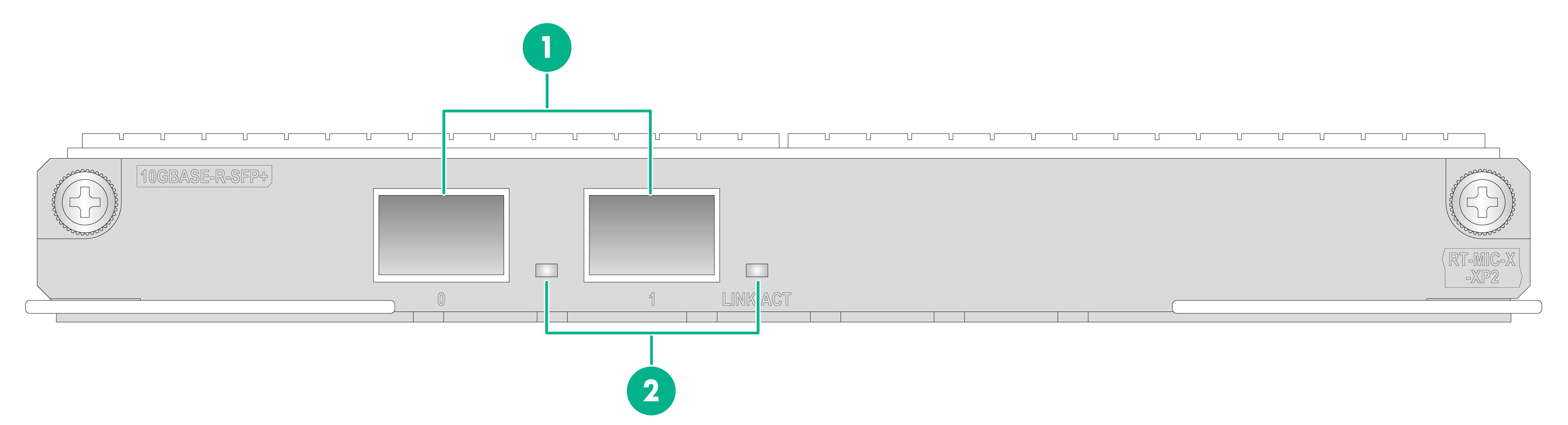
A MIC-X-XP2 10-GE optical interface card provides two 10-GE SFP+ ports.
Front panel
Figure1-1 Front panel
|
(1) 10GBASE-R-SFP+ ports 0 and 1 |
(2) 10GBASE-R-SFP+ port LEDs (LINK/ACT) |
LEDs
Table1-1 LED description
|
LED |
Status |
Description |
|
LINK/ACT |
Flashing |
Data is being received or transmitted at 10 Gbps. |
|
Steady on |
A 10 Gbps link is present. |
|
|
Off |
No link is present. |
Interface specifications
Table1-2 Interface specifications
|
Item |
Specification |
|
Interface type and quantity |
Two SFP+ ports |
|
Connector type |
LC |
|
Interface standard |
10GBASE-R |
|
Interface speed |
10.3125 Gbps |
Interface connection
Use transceiver modules and optical fibers to connect the ports on the interface card. For the transceiver modules available for the interface card, see Table1-15. For the connection procedure, see "Installing transceiver modules and optical fibers."
MIC-X-XP4
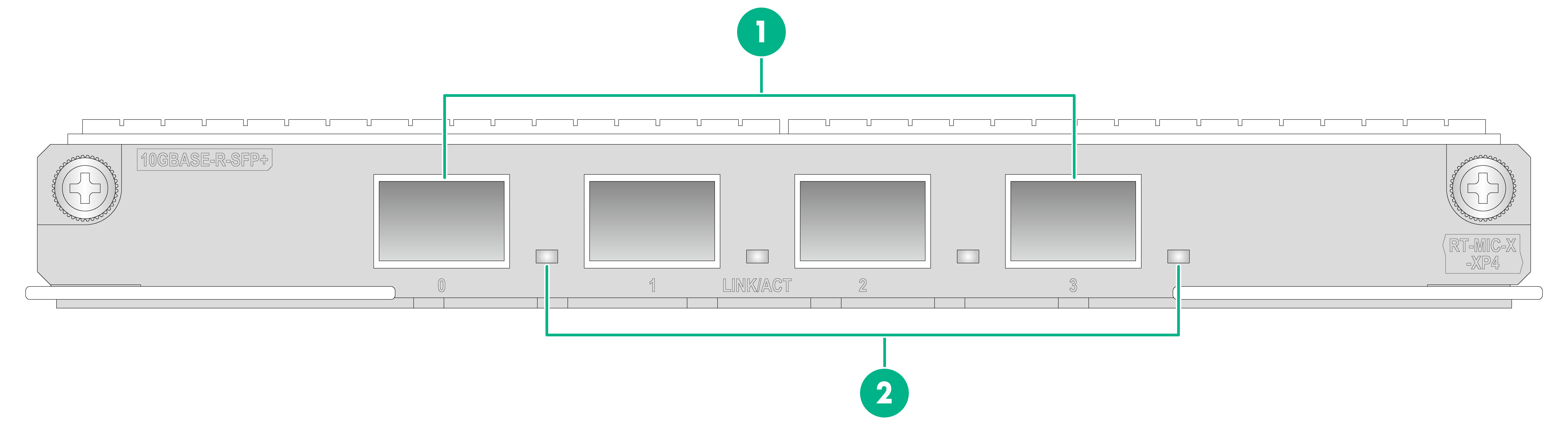
A MIC-X-XP4 10-GE optical interface card provides four 10-GE SFP+ ports.
Front panel
Figure1-2 Front panel
|
(1) 10GBASE-R-SFP+ ports 0 to 3 |
(2) 10GBASE-R-SFP+ port LEDs (LINK/ACT) |
LEDs
Table1-3 LED description
|
LED |
Status |
Description |
|
LINK/ACT |
Flashing |
Data is being received or transmitted at 10 Gbps. |
|
Steady on |
A 10 Gbps link is present. |
|
|
Off |
No link is present. |
Interface specifications
Table1-4 Interface specifications
|
Item |
Specification |
|
Interface type and quantity |
Four SFP+ ports |
|
Connector type |
LC |
|
Interface standard |
10GBASE-R |
|
Interface speed |
10.3125 Gbps |
Interface connection
Use transceiver modules and optical fibers to connect the ports on the interface card. For the transceiver modules available for the interface card, see Table1-15. For the connection procedure, see "Installing transceiver modules and optical fibers."
MIC-X-CLP2
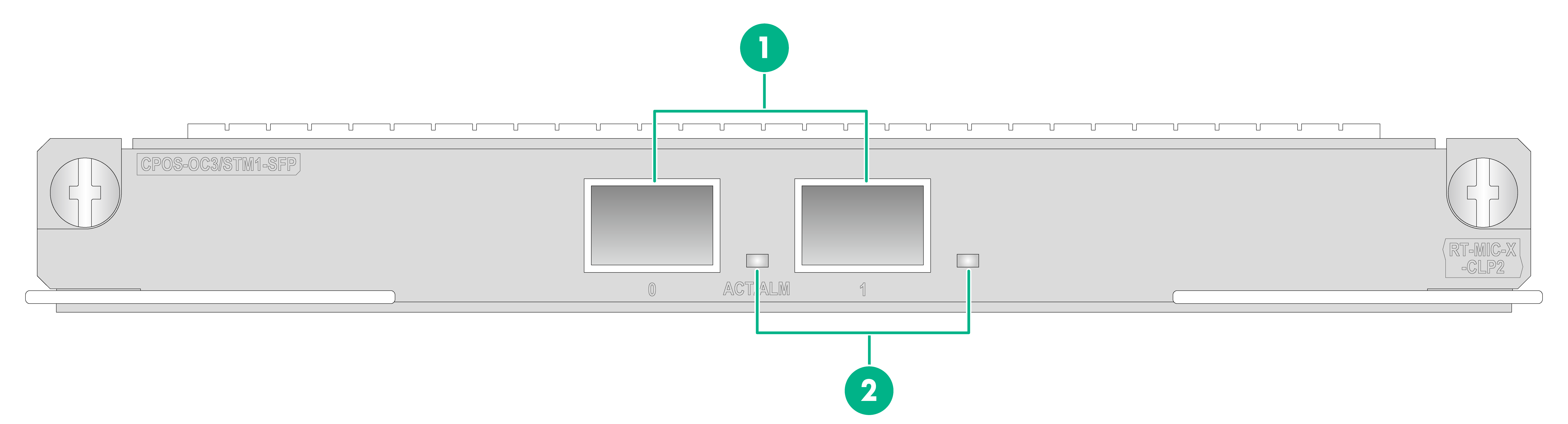
A MIC-X-CLP2 optical interface card provides two OC-3c/STM-1 CPOS ports.
Front panel
Figure1-3 Front panel
|
(1) 155M CPOS ports 0 and 1 |
(2)155M CPOS port LEDs (ACT/ALM) |
LEDs
Table1-5 LED description
|
LED |
Status |
Description |
|
155M CPOS port LED (ACT/ALM) |
Flashing green |
The port is sending or receiving data at 155.52 Mbps. |
|
Steady green |
A 155.52 Mbps link is present. |
|
|
Steady red |
A transceiver module has been installed in the port, but the port is down. |
|
|
Off |
No transceiver module has been installed in the port. |
Interface specifications
Table1-6 Interface specifications
|
Item |
Specification |
|
Interface type and quantity |
Two 155M CPOS SFP ports |
|
Connector type |
LC |
|
Interface standards |
SONET OC-3/SDH STM-1 |
|
Interface speed |
155.52 Mbps |
Interface connection
Use transceiver modules and optical fibers to connect the ports on the interface card. For the transceiver modules available for the interface card, see Table1-15. For the connection procedure, see "Installing transceiver modules and optical fibers."
MIC-X-CLP4
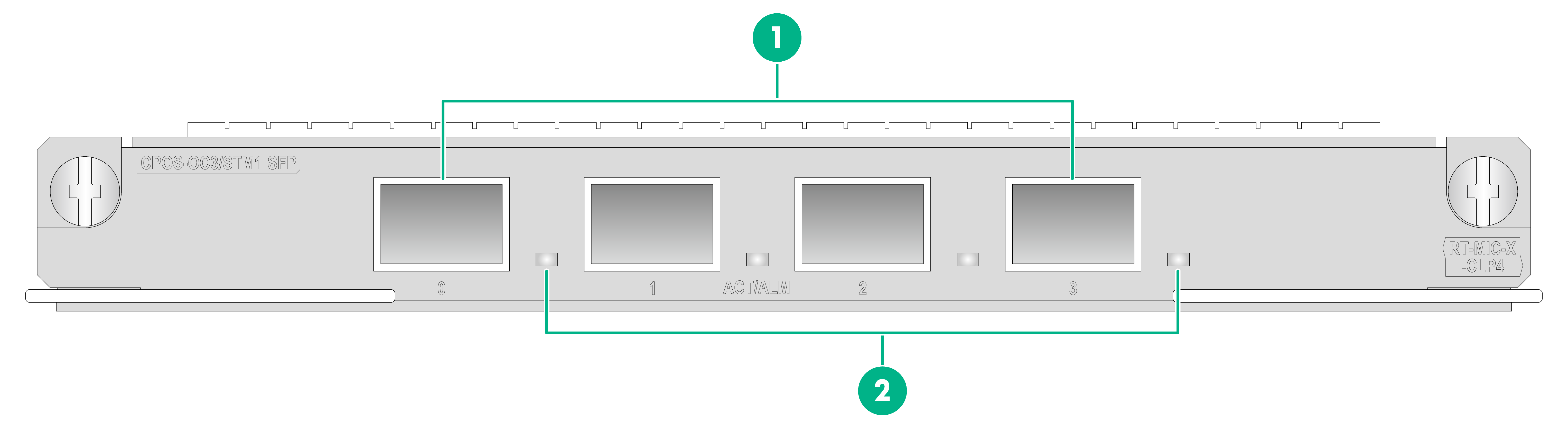
A MIC-X-CLP4 interface card provides four OC-3c/STM-1 CPOS ports.
Front panel
Figure1-4 Front panel
|
(1) 155M CPOS ports 0 to 3 |
(2) 155M CPOS port LEDs (ACT/ALM) |
LEDs
Table1-7 LED description
|
LED |
Status |
Description |
|
155M CPOS port LED (ACT/ALM) |
Flashing green |
The port is sending or receiving data at 155.52 Mbps. |
|
Steady green |
A 155.52 Mbps link is present on the port. |
|
|
Steady red |
A transceiver module has been installed in the port, but the port is down. |
|
|
Off |
No transceiver module has been installed in the port. |
Interface specifications
Table1-8 Interface specifications
|
Item |
Specification |
|
Interface type and quantity |
Four 155M CPOS SFP ports |
|
Connector type |
LC |
|
Interface standards |
SONET OC-3/SDH STM-1 |
|
Interface speed |
155.52 Mbps |
Interface connection
Use transceiver modules and optical fibers to connect the ports on the interface card. For the transceiver modules available for the interface card, see Table1-15. For the connection procedure, see "Installing transceiver modules and optical fibers."
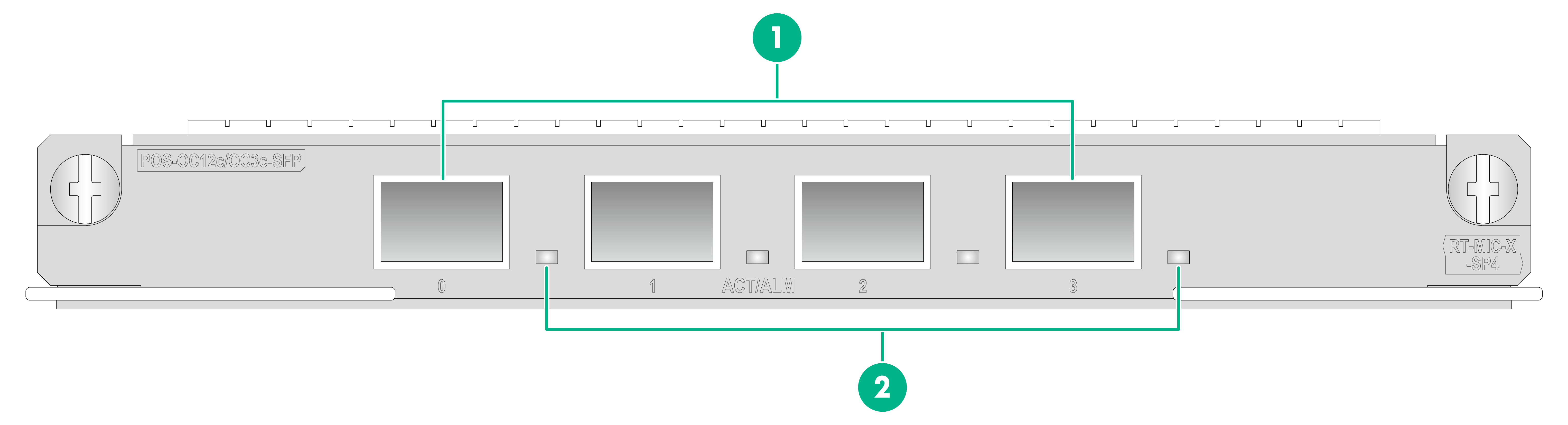
MIC-X-SP4
A MIC-X-SP4 optical interface card provides four fiber ports. You can use the card-mode command to configure the four fiber ports as OC-3c/STM-1c or OC-12c/STM-4c POS ports. By default, the ports are OC-3c/STM-1c POS ports.
|
|
IMPORTANT: If you configure the ports on a MIC-X-SP4 interface card as OC-12c/STM-4c POS ports, only port 0 works. The other three ports does not work. |
Front panel
Figure1-5 Front panel
|
(1) 155M/622M POS ports 0 to 3 |
(2) 155M/622M POS port LEDs (ACT/ALM) |
LEDs
Table1-9 LED description
|
LED |
Status |
Description |
|
155M/622M POS port LED (ACT/ALM) |
Flashing green |
The port is sending or receiving data at 155.52 Mbps or 622.08 Mbps. |
|
Steady green |
A 155.52 Mbps or 622.08 Mbps link is present on the port. |
|
|
Steady red |
A transceiver module has been installed in the port, but the port is down. |
|
|
Off |
No transceiver module has been installed in the port. |
Interface specifications
Table1-10 Interface specifications
|
Item |
Specification |
|
Interface type and quantity |
Four 155M/622M POS SFP ports |
|
Connector type |
LC |
|
Interface standard |
· SONET OC-3c/SDH STM-1 · SONET OC-12c/SDH STM-4 |
|
Interface speed |
· 155.52 Mbps · 622.08 Mbps |
Interface connection
Use transceiver modules and optical fibers to connect the ports on the interface card. For the transceiver modules available for the interface card, see Table1-15. For the connection procedure, see "Installing transceiver modules and optical fibers."
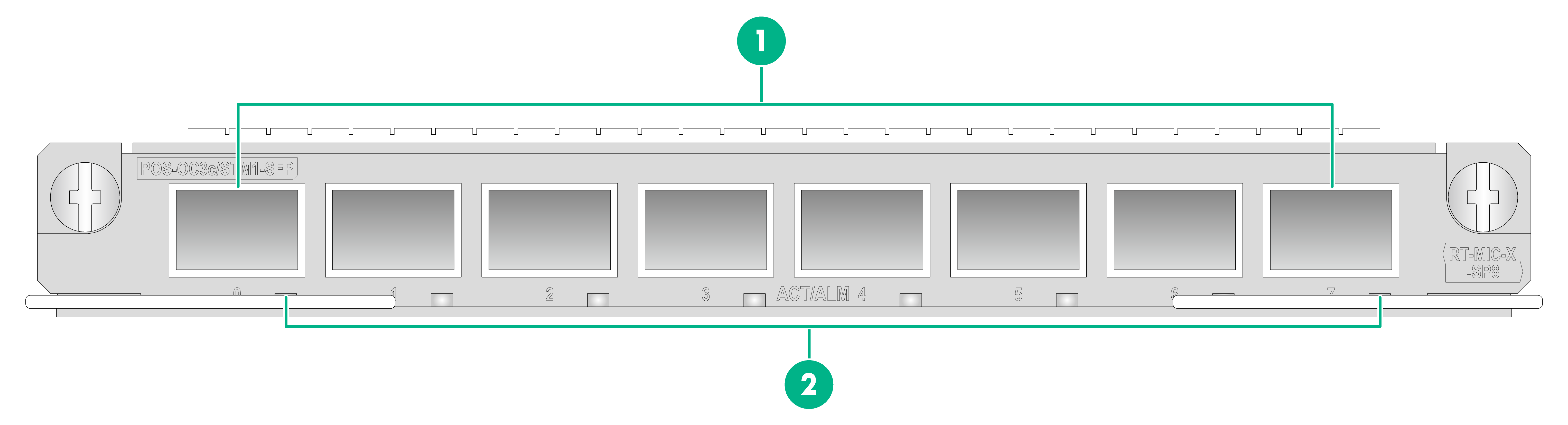
MIC-X-SP8
A MIC-X-SP8 optical interface card provides eight OC-3c/STM-1c POS ports.
Front panel
Figure1-6 Front panel
|
(1) 155M POS ports 0 to 7 |
(2) 155M POS port LEDs (ACT/ALM) |
LEDs
Table1-11 LED description
|
LED |
Status |
Description |
|
155M POS port LED (ACT/ALM) |
Flashing green |
The port is sending or receiving data at 155.52 Mbps. |
|
Steady green |
A 155.52 Mbps link is present on the port. |
|
|
Steady red |
A transceiver module has been installed in the port, but the port is down. |
|
|
Off |
No transceiver module has been installed in the port. |
Interface specifications
Table1-12 Interface specifications
|
Item |
Specification |
|
Interface type and quantity |
Eight 155M POS SFP ports |
|
Connector type |
LC |
|
Interface standard |
SONET OC-3c/SDH STM-1 |
|
Interface speed |
155.52 Mbps |
Interface connection
Use transceiver modules and optical fibers to connect the ports on the interface card. For the transceiver modules available for the interface card, see Table1-15. For the connection procedure, see "Installing transceiver modules and optical fibers."
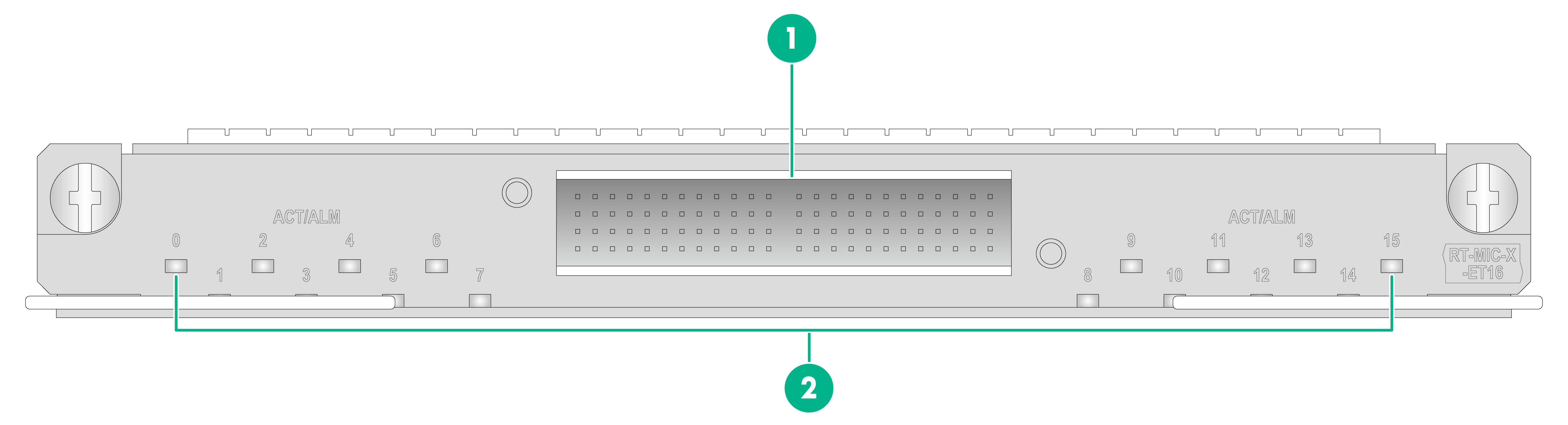
MIC-X-ET16
A MIC-X-ET16 interface card provides 16 E1 ports, which can operate in channelized or unchannelized mode. In unchannelized mode, each E1 port provides 2.048 Mbps of data bandwidth. In channelized mode, each E1 port is divided into 32 timeslots (each timeslot has a rate of 64 Kbps). Each timeslot can be used as a logical interface and supports timeslot bundling.
Front panel
Figure1-7 Front panel
|
(1) E1 ports (16 in total) |
(2) E1 port LEDs (ACT/ALM) |
LEDs
Table1-13 LED description
|
LED |
Status |
Description |
|
E1 port LED (ACT/ALM) |
Flashing green |
The interface is sending or receiving data at 2.048 Mbps. |
|
Steady green |
A 2.048 Mbps link is present on the port. |
|
|
Steady red |
An alarm has occurred. |
Interface specifications
Table1-14 Interface specifications
|
Item |
Specification |
|
Interface type and quantity |
16 E1 ports |
|
Connector type |
HM96 |
|
Interface rate |
2.048 Mbps |
|
Cable type |
BNC 75-ohm E1 cable, 3.0m, (HD96 female), SYFVZP-75-1-1 grey, 32*BNCSM |
|
Cable characteristic impedance |
75 ohm |
Interface connection
Use E1 cables to connect the E1 ports on the interface card. For the connection procedure, see "Connecting cables to E1 ports."
Connecting interface cables
Connecting cables to fiber ports
Transceiver modules
To connect a fiber port, install an SFP or SFP+ transceiver module in the fiber port and then connect an optical fiber with LC-type connector to the transceiver module.
For specifications of transceiver modules, see H3C Transceiver Modules User Guide.
Table1-15 Compatibility between the interface cards and transceiver modules
|
Interface card model |
Applicable transceiver module type |
Applicable transceiver module model |
|
MIC-X-XP2 MIC-X-XP4 |
10G SFP+ transceiver module |
SFP-XG-SX-MM850-A SFP-XG-SX-MM850-D SFP-XG-SX-MM850-E SFP-XG-LX-SM1310 SFP-XG-LX-SM1310-D SFP-XG-LX-SM1310-E SFP-XG-LH40-SM1550 SFP-XG-LH40-SM1550-D BD-SFP-XG-SX-MM850-A1-F BD-SFP-XG-SX-MM850-E1-F SFP-XG-LH80-SM1550 SFP-XG-LH80-SM1550-D |
|
1000-Mbps SFP transceiver module |
SFP-GE-SX-MM850-A SFP-GE-SX-MM850-D SFP-GE-LX-SM1310-A SFP-GE-LX-SM1310-D SFP-GE-LH40-SM1310 SFP-GE-LH40-SM1310-D SFP-GE-LH40-SM1550 SFP-GE-LH80-SM1550 SFP-GE-LH80-SM1550-D SFP-GE-LH100-SM1550 |
|
|
1000-Mbps BIDI transceiver module |
SFP-GE-LX-SM1310-BIDI SFP-GE-LX-SM1490-BIDI |
|
|
MIC-X-CLP2 MIC-X-CLP4 MIC-X-SP4 MIC-X-SP8 |
100-Mbps SFP transceiver module |
SFP-FE-SX-MM1310-A SFP-FE-LX-SM1310-A SFP-FE-LX-SM1310-D SFP-FE-LH40-SM1310 SFP-FE-LH80-SM1550 |
|
100-Mbps BIDI transceiver module |
SFP-FE-LX-SM1310-BIDI SFP-FE-LX-SM1550-BIDI |
|
|
MIC-X-SP4 |
622-Mbps SFP transceiver module |
SFP-622M-LX-SM1310 SFP-622M-LX-SM1310-Z |
|
|
NOTE: · The BIDI transceiver module uses different central wavelengths in the sending and receiving directions to achieve bidirectional transmission of the optical signals in a single fiber. · You must use two BIDI transceiver modules in pairs. For example, if one end uses the SFP-FE-LX-SM1310-BIDI transceiver module, the peer end must use the SFP-FE-LX-SM1550-BIDI transceiver module. |
Installing transceiver modules and optical fibers
|
|
WARNING! Disconnected optical fibers or transceiver modules might emit invisible laser light. Do not stare into beams or view directly with optical instruments when the device is operating. |
|
|
CAUTION: · Never bend an optical fiber excessively. The bend radius of an optical fiber must be not less than 100 mm (3.94 in). · Keep the fiber end clean. · To connect an optical fiber to a fiber port, make sure the fiber connector matches the transceiver module. · Before connecting an optical fiber, make sure the received optical power does not exceed the upper receive power threshold of the transceiver module. If the threshold is exceeded, the transceiver module might be damaged. · To connect an optical fiber to a fiber port, first install a transceiver module in the fiber port and then connect the optical fiber to the transceiver module. · Insert a dust plug into any open fiber port. |
The transceiver module appearance varies by model. The transceiver modules in the following figures are for illustration only.
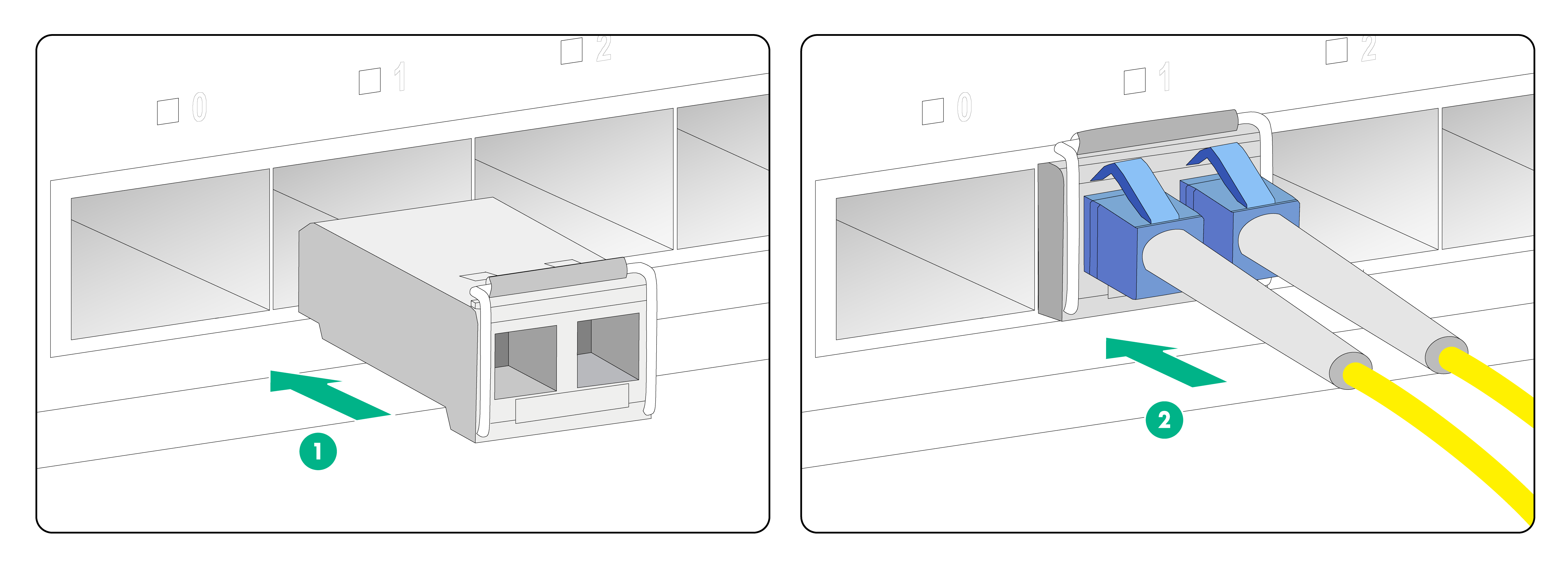
To installing a transceiver module and optical fiber:
1. Remove the dust plug from the fiber port.
2. Pivot the clasp of the transceiver module up to catch the clip on the top. Hold the two sides of the transceiver module and insert it slowly into the fiber port.
3. Remove the dust cap from the optical fiber connector, and use dust-free paper and absolute ethanol to clean the end face of the fiber connector.
4. Identify the Rx and Tx ports on the transceiver module. Use the optical fiber to connect the Rx port and the Tx port on the transceiver module to the Tx port and the Rx port on the peer device, respectively.
Figure1-8 Connecting a transceiver module and optical fiber
Connecting cables to E1 ports
E1 cables
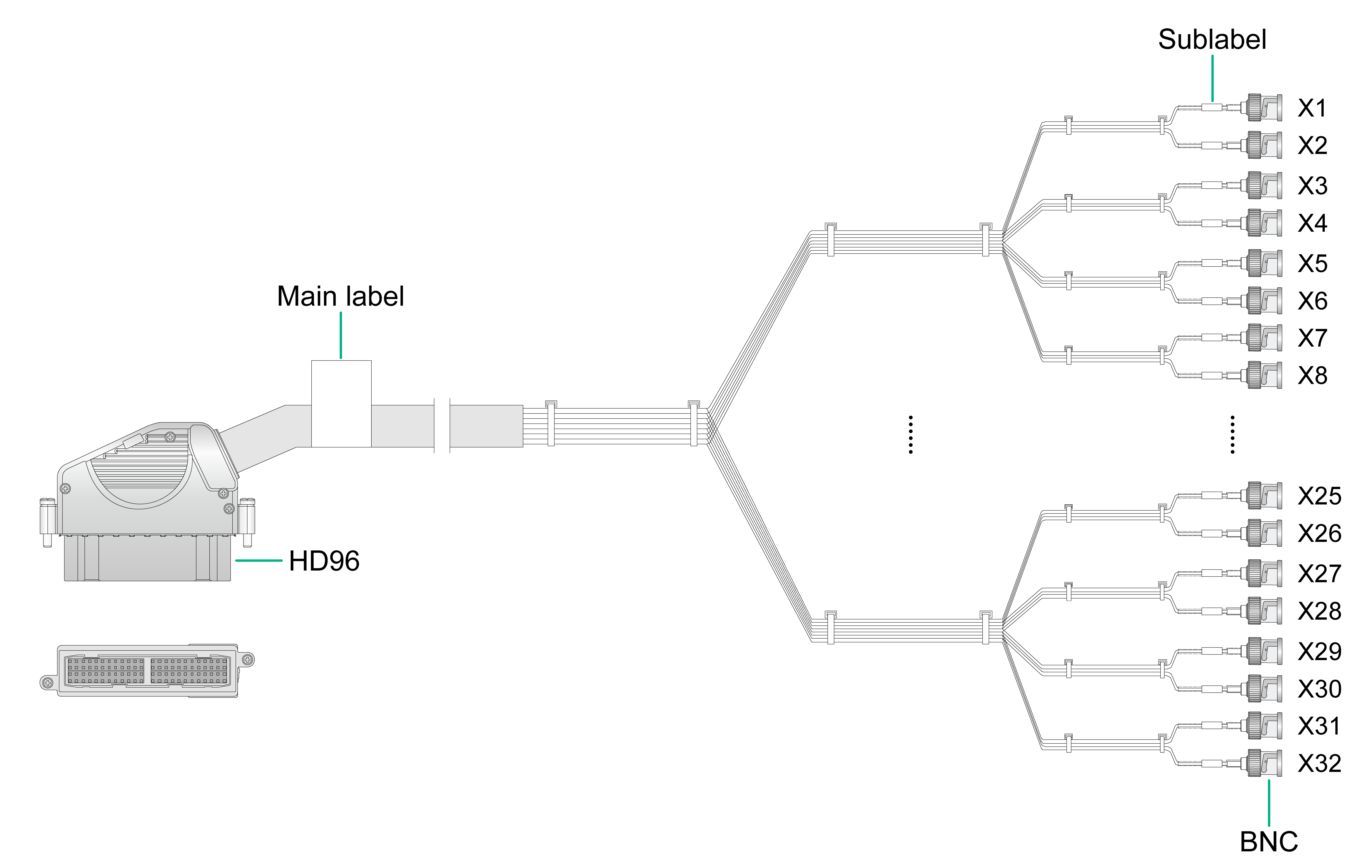
You can use an E1 cable to connect E1 ports (HM96 male connector). Typically, an E1 cable has an HD96 female connector at one end and multiple BNC connectors at the other end.
When connecting an E1 cable, you might need also coaxial connectors and 75-ohm E1 adapter cables. No coaxial connectors and 75-ohm E1 adapter cables are provided with the interface cards. Purchase them yourself as needed.
Figure1-9 E1 cable
Connecting an E1 75-ohm BNC cable
|
|
CAUTION: To avoid interface card or chassis damage, identify the target E1 port before your connection. Avoid connecting the cable to another port. |
To connect an E1 75-ohm BNC cable:
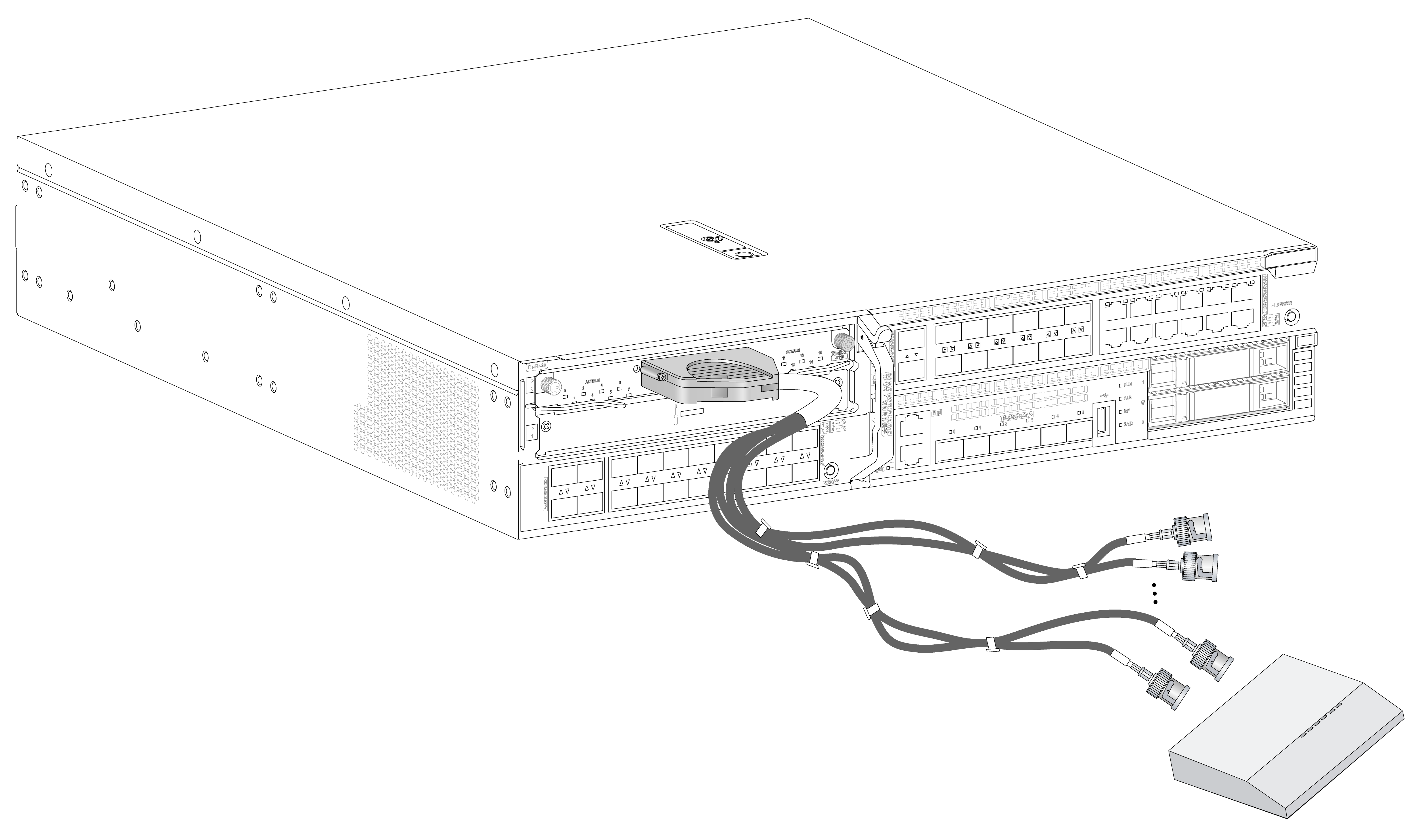
· If you do not need to extend the cable, perform these steps:
a. Connect the HD96 female connector of the E1 75-ohm cable to the HM96 connector on the interface card and fasten the screws on the connector.
b. The other end of the cable provides multiple pairs of 75-ohm BNC connectors. Identify the number of each pair of BNC connectors. Connect the TX connector and the RX connector of the cable to the RX connector and the TX connector on the peer device, respectively.
Figure1-10 Connecting an E1 75-ohm cable
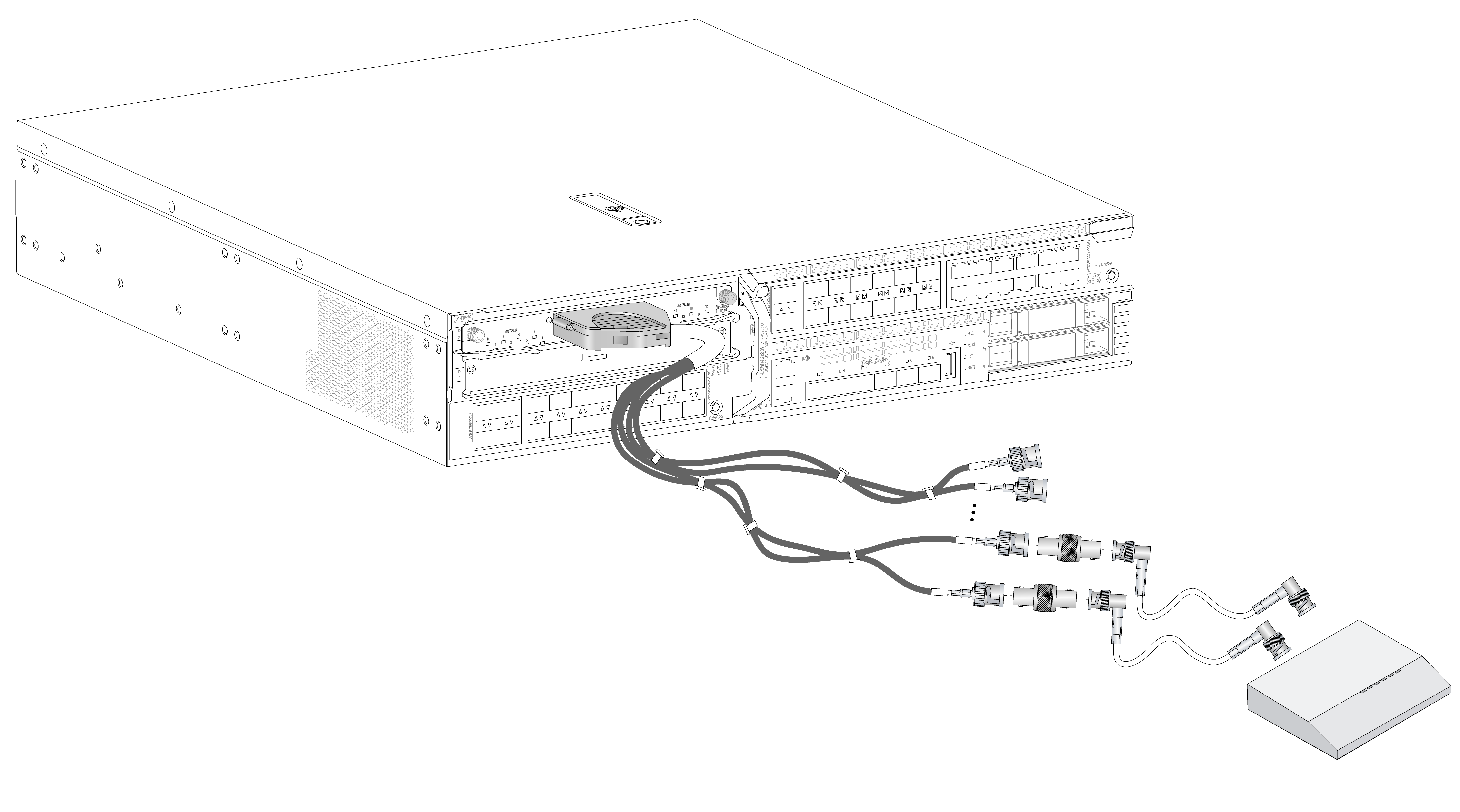
· If you need to extend the cable, connect each BNC connector of the E1 75-ohm cable to a coaxial connector and then use an E1 75-ohm adapter cable to connect the coaxial connector to the peer device.
Figure1-11 Connecting an E1 75-ohm cable (using coaxial connectors and 75-ohm adapter cables)
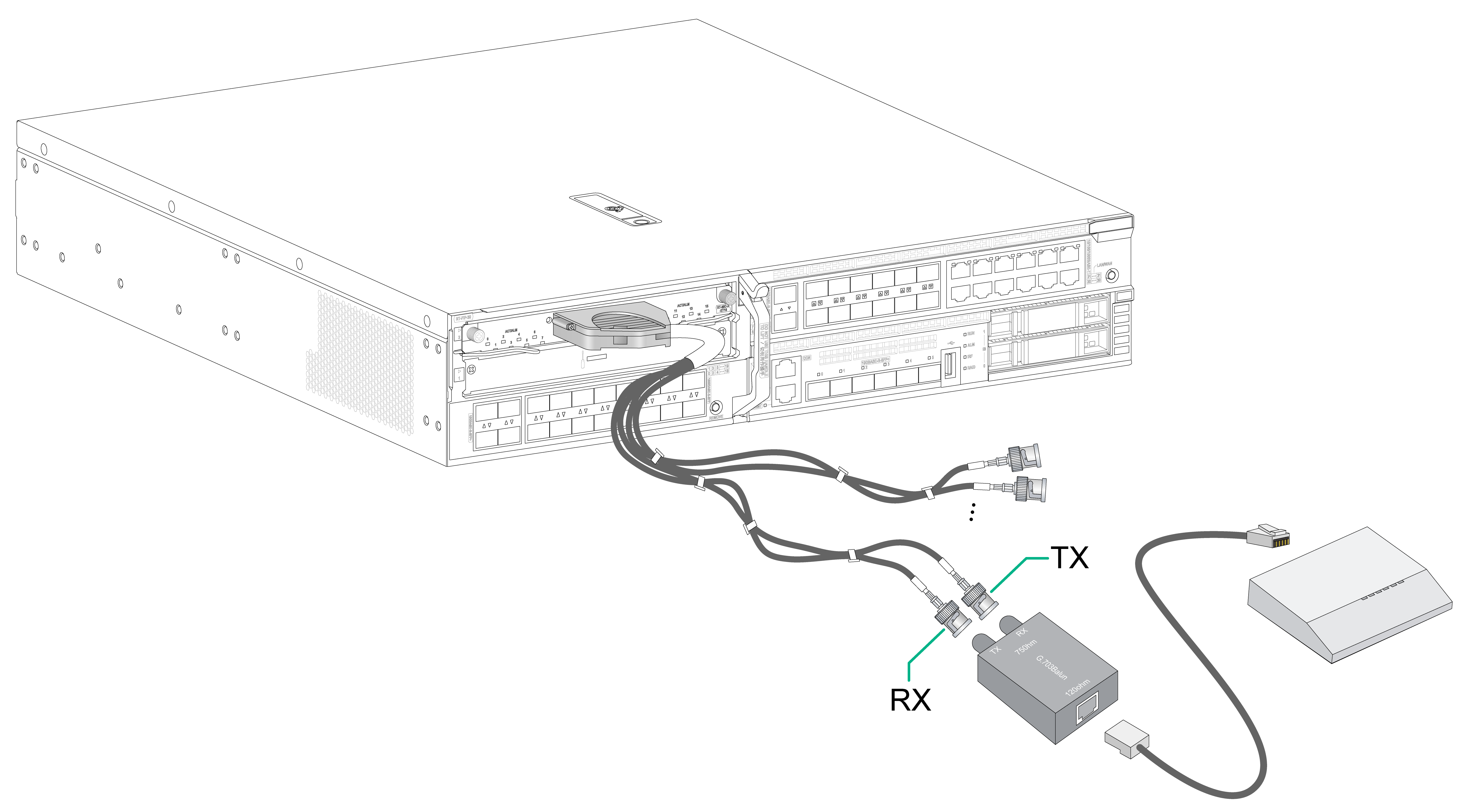
· If the impedance of the E1 port on the peer device is 120 ohms, you must use an impedance converter to adapt the impedance.
a. Connect the TX connector and the RX connector of the cable to the RX connector and the TX connector on the impedance converter, respectively.
b. Use a network cable to connect the other end of the impedance converter to the peer device.
Figure1-12 Connecting an E1 75-ohm cable (using an impedance converter)