- Table of Contents
- Related Documents
-
| Title | Size | Download |
|---|---|---|
| 01-Text | 5.13 MB |
1.1.1 General operating safety
1.2.1 Preventing electrostatic discharge
1.2.2 Grounding methods to prevent electrostatic discharge
4 Software and Hardware Compatibility Relationship
4.1 Supported Operating Systems
4.2 Blade Servers Supported by the NIC
4.3.1 Compatibility between the NIC and ICM
4.3.2 Connection Between the NIC and ICM
4.4 Network Application Logic Diagram
5.1 Port Correspondence between the NIC and ICM
5.2 Identification of network card ports in the operating system
5.2.2 Windows Operating Systems
5.3 Installing and removing a network adapter driver in the operating system
5.3.2 Windows Operating Systems
5.4 Changing the network adapter mode
5.5 Configuring IB network properties
5.5.1 Running the OpenSM in the Linux operating system
5.6 Configuring Ethernet properties
5.10 Configuring advanced features
1 Safety
1.1 Safety information
To avoid personal injury or device damage, read the following information carefully before you operate the network adapter.
1.1.1 General operating safety
To avoid personal injury or damage to the device, follow these guidelines when you operate the network adapter:
· Only H3C authorized or professional engineers are allowed to install or replace the network adapter.
· Before installing or replacing the network adapter, stop all services, power off the blade server, and then remove the blade server.
· When disassembling, transporting, or placing the blade server, do not use excessive force. Make sure you use even force and move the device slowly.
· Place the blade server on a clean, stable workbench or floor for servicing.
· To avoid being burnt, allow the blade server and its internal modules to cool before touching them.
1.1.2 Electrical safety
Clear the work area of possible electricity hazards, such as ungrounded chassis, missing safety grounds, and wet work area.
1.2 ESD prevention
1.2.1 Preventing electrostatic discharge
Electrostatic charges that build up on people and other conductors might damage or shorten the lifespan of the network adapter.
To prevent electrostatic damage, follow these guidelines:
· Transport or store the network adapter in an antistatic bag.
· Keep the network adapters in antistatic bags until they arrive at an ESD-protected area.
· Place the network adapter on an antistatic workbench before removing it from its antistatic bag.
· Install the network adapter immediately after you remove it from its antistatic bag.
· Avoid touching pins, leads, or circuitry.
· Put away the removed network adapter in an antistatic bag immediately and keep it secure for future use.
1.2.2 Grounding methods to prevent electrostatic discharge
The following are grounding methods that you can use to prevent electrostatic discharge:
· Wear an ESD wrist strap and make sure it makes good skin contact and is reliably grounded.
· Take adequate personal grounding measures, including wearing antistatic clothing and static dissipative shoes.
· Use conductive field service tools.
· Use a portable field service kit with a folding static-dissipating work mat.
2 About the NIC
![]() Note
Note
Figures in this manual are for illustration purposes only. The actual product may vary.
2.1 Overview
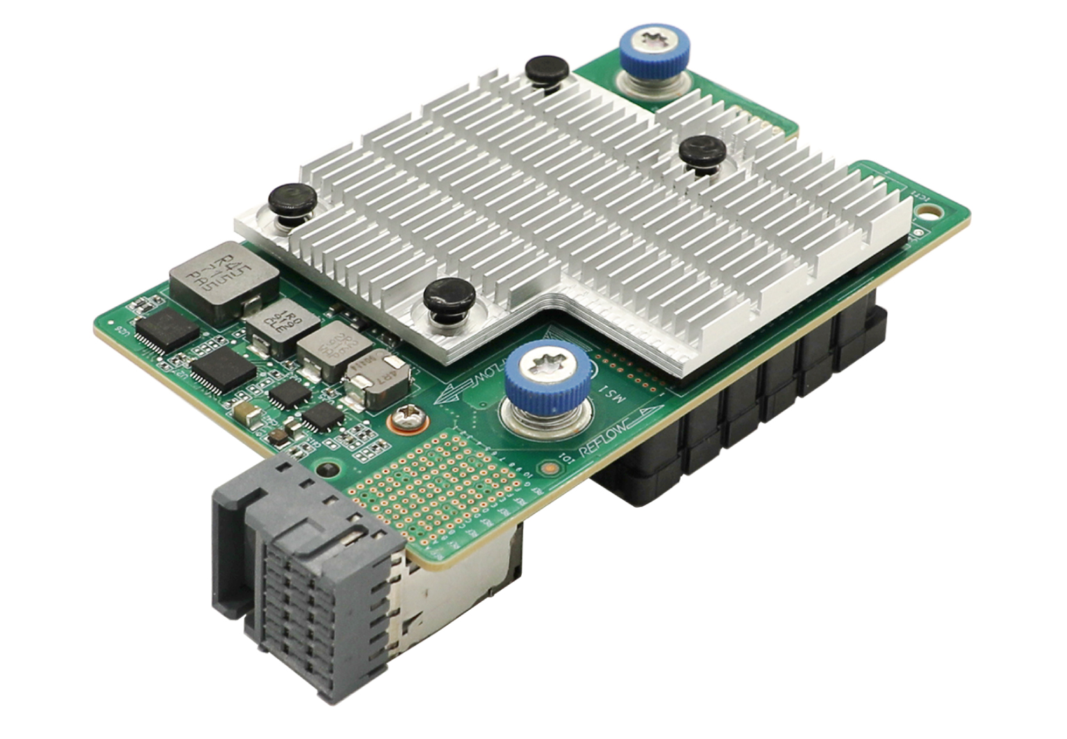
IB1040i (product model: IB1040i-Mb-2*100G) is an InfiniBand network adapter that provides two 100G ports. It can be applied to the UniServer B16000 blade servers to provide network interfaces connecting blade servers to ICMs. The IB1040i exchanges data with blade servers by using PCIe x16 channels, uses the two 100G IB EDR ports to connect to the ICMs through the mid plane, and supports the HCA application.
2.2 Appearance
Figure 2-1 shows the appearance of IB1040i. The IB1040i network adapter can be applied to 2-processor half-width, 2-processor full-width, and 4-processor full-width B16000 blade servers. For the installation positions of the network adapter, see "4.2 Blade Servers Supported by the NIC."
Figure 2-1 Appearance of IB1040i
2.3 Specifications
This section introduces the product specifications and technical parameters of the NIC.
2.3.1 Product Specifications
Table 2-1 Product Specifications
|
Properties |
Description |
|
Basic properties |
|
|
NIC type |
IB NIC |
|
Chip model |
MT27808A0-FCCF-EV |
|
Max. power consumption |
20 W |
|
Data channel bus |
PCIe3.0 x16 |
|
Network properties |
|
|
Number and type of user ports |
2*100G |
|
User port transfer rate |
100 Gb/s |
|
Full duplex/Half duplex |
Full duplex |
|
Compatible standards |
802.3az, 802.3ba, 802.3bj, 802.3bm, 802.3ae, 802.3az, 802.3ap, 802.3ad, 802.1Q, 802.1p, 802.1Qau, 802.1Qaz, 802.1Qbb, 802.1Qbg |
2.3.2 Specifications
Table 2-2 Specifications
|
Category |
Item |
Description |
|
Physical specifications |
Dimensions (H × W × D) |
25.05 mm x 61.60 mm x 95.00 mm |
|
Environmental specifications |
Temperature |
Operating temperature: 5°C to 35°C |
|
Storage temperature: -40°C to 70°C |
||
|
Humidity |
· Operating humidity: 8% to 90%RH (non-condensing) · Storage humidity: 5% to 95%RH (non-condensing) |
|
|
Altitude |
· Operating altitude: -60 m to +5000 m (The allowed maximum temperature decreases by 0.33°C as the altitude increases by 100 m from 900 m.) · Storage altitude: -60 m to +5000 m |
3 Feature Introduction
3.1 Supported Features
This section introduces the features supported by the IB1040i NIC.
Table 3-1 NIC features
|
Feature |
Supported |
|
InfiniBand |
√ |
|
Jumbo frames |
√ |
|
RDMA |
√ |
|
Load balancing |
√ |
|
802.1Q VLANs |
√ |
|
Auto negotiation |
√ |
|
PXE Boot |
√ |
|
iSCSI |
√ |
|
SR-IOV |
√ |
|
VMDq |
× |
|
Multiple Rx Queues (RSS) |
√ |
|
TCP/IP Stateless Offloading |
√ |
|
Wake-on-LAN |
× |
|
NIC bonding |
√ |
3.2 Function Introduction
1. InfiniBand
The IB1040i network adapter supports InfiniBand.
InfiniBand directly creates a private and protected channel between nodes through the switch to transmit data and messages. The transmission process does not require the participation of CPU, and the memory can be directly accessed. Data sending/receiving is managed and executed by the InfiniBand adapter. One end of the adapter is connected to the CPU, and the other end is connected to the InfiniBand subnet through the InfiniBand network port. Compared with other network communication protocols, InfiniBand provides obvious advantages, including higher bandwidth, lower latency, and strong scalability.
2. OpenSM
OpenSM is an InfiniBand-compliant Subnet Manager (SM) that runs on the Mellanox OFED software stack for IB network management. It initializes the hardware that conforms to the InfiniBand specification. One SM must run in each InfiniBand subnet. OpenSM is attached to a specified IB port of the local host and manages the components connected to it. If no port is specified, OpenSM will select the first "optimum" available port.
3. IPoIB
Both ports of the IB1040i network adapter support IPoIB.
IPoIB encapsulates IP packets on the IB link for transmission. The IPoIB port is identified as ibX under the operating system. IPoIB can configure IP addresses to implement the following functions: IPv4/IPv6 address resolution, IPv4/IPv6 packet encapsulation, network initialization, multicast, broadcast, and management information base (MIB).
4. PXE
The IB1040i network adapter supports PXE boot. During booting, the blade server, which acts as the PXE client, obtains an IP address from the PXE server, uses TFTP to download and run the PXE boot file, and completes the basic software configuration of the client to realize PXE boot of the client. PXE enables the server to boot without relying on the local data storage device or locally installed operating system.
5. iSCSI
Both ports on the IB1040i network adapter support iSCSI SAN, but not iSCSI remote boot.
iSCSI is a new storage technology which integrates SCSI interfaces and Ethernet. Based on iSCSI, the device can transmit commands and data through SCSI interfaces on the network so that cross-province and cross-city storage resource sharing can be realized among equipment rooms. iSCSI also supports storage capacity expansion without service interruption, and provides storage resources for multiple servers.
6. SR-IOV
Both ports of the IB1040i network adapter support SR-IOV.
SR-IOV allows users to integrate network hardware resources and run multiple VMs on the integrated hardware. SR-IOV also provides users with rich features, such as I/O sharing, integration, isolation, migration, and simplified management. SR-IOV may cause performance degradation due to the overhead of the hypervisor. PCI-SIG introduced the SR-IOV specification to solve the performance issue by creating VF. The PCIe Virtual Function (VF) is a lightweight PCIe function that is directly allocated to VMs, bypassing the hypervisor layer to move master data.
PCIe Physical Function (PF) is a full-featured PCIe function, whereas VF is a lightweight PCIe function separated from PF. VFs can be directly assigned to corresponding applications. VF shares the resources of physical devices and performs I/O without CPU and VM manager overhead.
The IB1040i network adapter supports creation of 0 to 127 VFs for each physical port and a total of 254 VFs.
7. VLAN
· 802.1Q VLAN
Each port on the IB1040i network adapter supports a maximum of 4094 VLANs, and the VLAN ID ranges from 1 to 4094.
The network adapter only transmits packets, and does not tag or untag packets. The VLAN ID is assigned by the operating system.
A VLAN is a group of logical devices and users working at Layer 2 and Layer 3 in the OSI model. A VLAN is a broadcast domain. Communication between VLANs is implemented by Layer 3 routers. Compared with LAN, VLAN is more flexible. VLAN has less overhead added or modified, and can control broadcast activities to enhance network security.
8. Bonding (Linux)
Bonding has the following seven modes, of which the commonly used modes are mode=0, mode=1 and mode=6. The IB1040i network adapter only supports mode=1 (active-backup).
· mode=0, round-robin policy (balance-rr): Data packets are transmitted between backup devices in sequence.
· mode=1, active-backup policy (active-backup): Only the master device is in active state. A backup device takes over the services when the master device fails.
· mode=2, XOR policy (balance-xor): Data packets are transmitted based on a specified transmission hash policy.
· mode=3, broadcast policy: Data packets are transmitted on the interface of each backup device. This mode is error tolerant.
· mode=4, IEEE 802.3ad dynamic link aggregation (802.3ad): An aggregation group is created where group members share the same rated speed and full duplex mode settings. Backup devices for outbound traffic are selected based on transmission hash policy. In this mode, the switch must support IEEE 802.3ad and have special configurations.
· mode=5, adaptive transmit load balancing (balance-tlb): This mode does not require switches. In this mode, outbound traffic is allocated to backup devices according to the device loads. If a backup device that is receiving traffic is faulty, another backup device takes over the MAC address of the faulty backup device.
· mode=6, adaptive load balancing (balance-alb): This mode integrates the balance-tlb mode and load balancing of received IPv4 packets. It is realized by ARP negotiation and does not require switches. The bonding driver intercepts the ARP replies sent by the local device and changes the source MAC address into a unique MAC address of a backup device in bonding, allowing different peers to communicate using different MAC addresses.
9. Teaming (Windows)
Taking the teaming solution integrated in Windows Server 2012 R2 as an example, there are three NIC teaming modes:
· Static teaming: A switch-dependent mode in which member NICs must connect to the same physical switch.
· Switch independent: Member NICs can be connected to different switches in active/standby mode. Load balancing aggregation can be realized only when the member NICs connect to the same switch.
· LACP: You must enable LACP on the switch first. This mode integrates multiple NICs into one logical link. Data is transmitted at the fastest speed in LACP mode.
After configuring the teaming mode, you must configure the load balancing mode. Load balancing has the following modes:
· Address hash mode: In this mode, when a packet arrives at the team, the device uses the hash algorithm to determine the physical NIC for sending packets based on the destination address information (MAC address, IP address, and port number). This mode cannot control traffic direction. If a large amount of traffic goes to the same destination address, the traffic will be sent by the same physical NIC.
· Hyper-V port mode: Compared with the address hash mode, this mode has higher traffic distribution efficiency. In this mode, data are transmitted by different physical NICs bound to the vNIC and the binding is based on vNICs instead of VMs. As a best practice, enable this mode when you use a Hyper-V external virtual switch.
· Dynamic mode: It is the optimal load balancing mode introduced for Windows Server 2016. In this mode, data is evenly distributed to all NICs to make full use of bandwidth.
10. TCP offloading
TCP offloading is a TCP acceleration technology that moves the load of the TCP/IP stack to the NIC and use the NIC hardware to process the load. On a high speed Ethernet, processing TCP/IP packet headers consumes great CPU resources. Using the NIC hardware to process the headers can ease the CPU burden, and the saved CPU resources can be used for other applications.
11. RDMA
Remote Direct Memory Access (RDMA) is tailored to deal with the data processing delay on the server during network transmission. It directly transmits data to the storage area of a computer through network and rapidly moves data from a system to the storage media of a remote system without impacting the operating system. It uses zero overhead for copying and context switching of the external storage media, thus freeing memory bandwidth and CPU cycles to optimize the application system performance.
4 Software and Hardware Compatibility Relationship
4.1 Supported Operating Systems
For details about compatibility between the network adapter and operating system, see OS compatibility query tool.
4.2 Blade Servers Supported by the NIC
Table 4-1 describes the blade server models supported by the NIC and their installation positions.
Table 4-1 Blade Servers Supported by the NIC
|
Model of Blade Server |
Model of Blade Server |
Number of Mezz NIC Slots |
Installation Position |
Diagram |
|
H3C UniServer B5700 G3 |
2-way half-width blade server |
3 |
Mezz 1, Mezz 2 and Mezz 3 |
NIC installation position on a 2-way half-width blade server |
|
H3C UniServer B5800 G3 |
2-way full-width blade server |
3 |
Mezz 1, Mezz 2 and Mezz 3 |
NIC installation position on a 2-way full-width blade server |
|
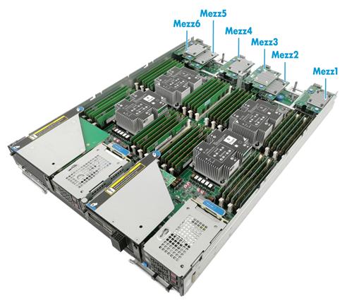
H3C UniServer B7800 G3 |
4-way full-width blade server |
6 |
Mezz 1, Mezz 2, Mezz 3, Mezz 4, Mezz 5 and Mezz 6 |
NIC installation position on a 4-way full-width blade server |
|
H3C UniServer B5700 G5 |
2-way half-width blade server |
3 |
Mezz 1, Mezz 2 and Mezz 3 |
NIC installation position on a 2-way half-width blade server |
Figure 4-1 NIC installation position on a 2-way half-width blade server
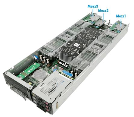
Figure 4-2 NIC installation position on a 2-way full-width blade server
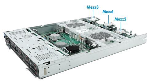
Figure 4-3 NIC installation position on a 4-way full-width blade server
4.3 ICMs Supported by NIC
4.3.1 Compatibility between the NIC and ICM
· ICM supported by the IB1040i network adapter: H3C UniServer BX1020B
4.3.2 Connection Between the NIC and ICM
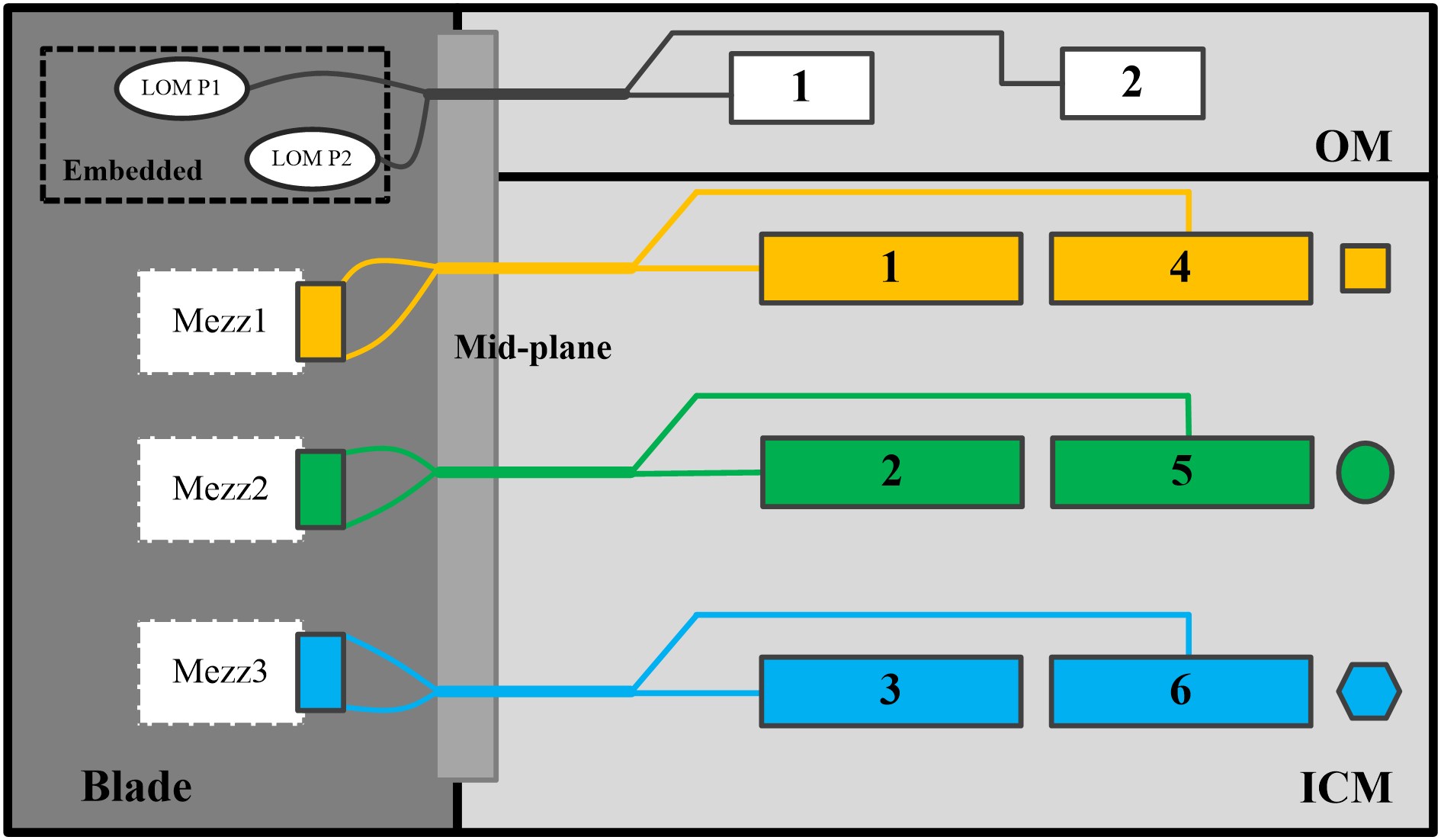
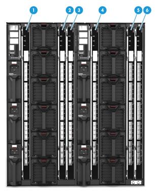
IB1040i NIC is connected to the ICM through the mid-backplane. When it is installed on the 2-way half-width or 2-way full-width blade server, the connection between it and the ICM slots is shown in Figure 4-4. Figure 4-6 shows the ICM slots.
· The NIC in Mezz 1 position is connected to the ICMs in slots 1 and 4.
· The NIC in Mezz 2 position is connected to the ICMs in slots 2 and 5.
· The NIC in Mezz 3 position is connected to the ICMs in slots 3 and 6.
Figure 4-4 Logical diagram of the connection relationship between the Mezz NIC slots and ICMs for 2-way half-width and 2-way full-width blade servers
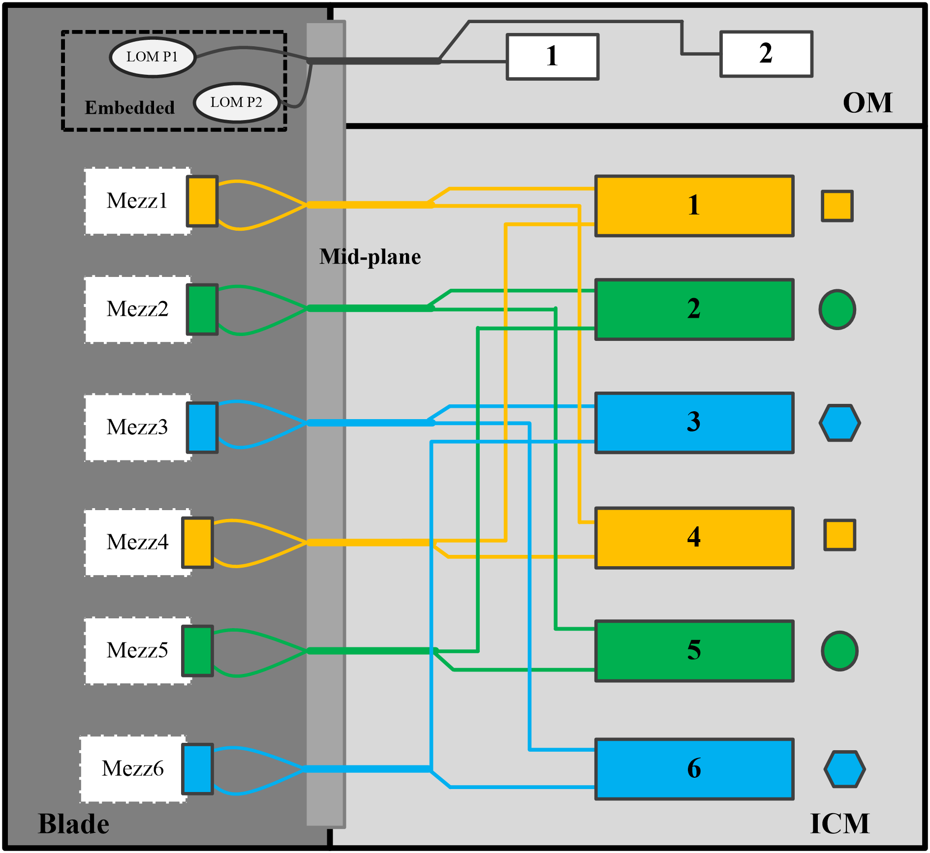
When the IB1040i is installed on a 4-way full-width blade server, the connection between it and the ICM slots is shown in Figure 4-5. Figure 4-6 shows the ICM slots.
· NICs in Mezz 1 and Mezz 4 positions are connected to the ICMs in slots 1 and 4.
· NICs in Mezz 2 and Mezz 5 positions are connected to the ICMs in slots 2 and 5.
· NICs in Mezz 3 and Mezz 6 positions are connected to the ICMs in slots 3 and 6.
Figure 4-5 Logical diagram of the connection relationship between the Mezz NIC slots and ICMs for 4-way full-width blade servers
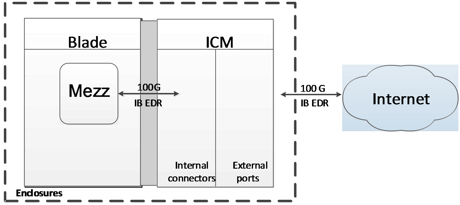
4.4 Network Application Logic Diagram
The IB1040i can be connected to the internal ports of the ICM. Each port provides 100G service applications. The external ports of the ICM are connected to the Internet to provide Internet access for the blade server where the Mezz network adapter is installed.
Figure 4-7 Connection between the Mezz NIC and ICM
5 Configuring the NIC
![]() Note
Note
The software UI shown in this manual is specific to a certain software version. The software UI may be updated from time to time. Please refer to the actual product UI.
5.1 Port Correspondence between the NIC and ICM
For the port correspondence between the Mezz NIC and ICM, check it at ICM Management > Port Mapping in the OM web UI, or query with Networking query tool.
5.2 Identification of network card ports in the operating system
This section describes how to confirm that the ports of the IB1040i network adapter have been identified in the operating system.
It uses CentOS 7.5 and Windows Server 2016 as examples.
5.2.1 Linux Operating Systems
(1) Execute the lspci | grep MT27800 command to view PCI information of the IB1040i network adapter. The system can identify two PCI devices, which correspond to two ports of the network adapter, as shown in Figure 5-1.
Figure 5-1 Viewing the PCI information

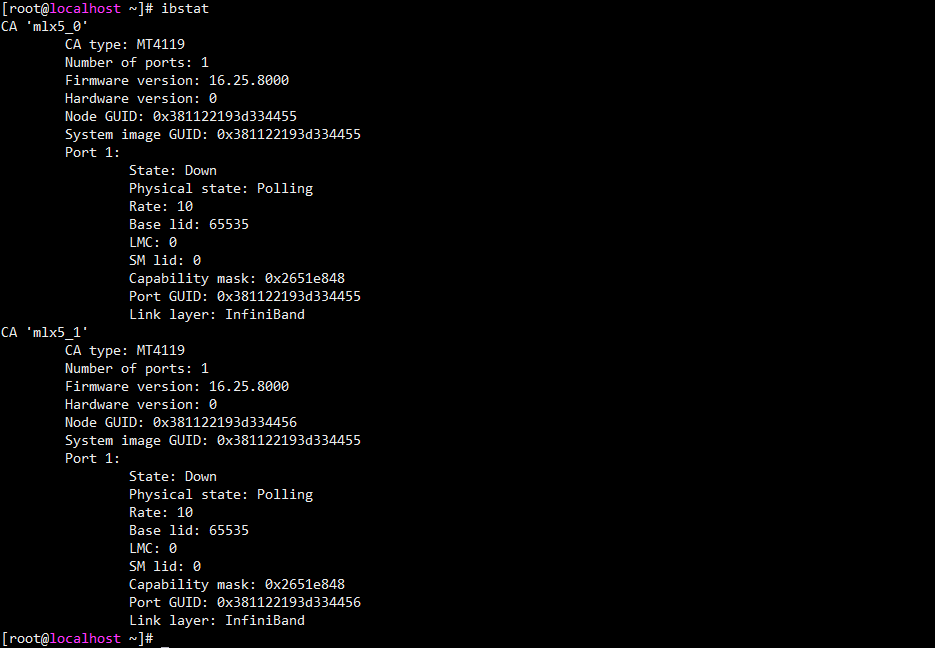
(2) Execute the ibstat command to view the information of two ports. Each port corresponds to a GUID address.
Figure 5-2 Viewing the network adapter port information
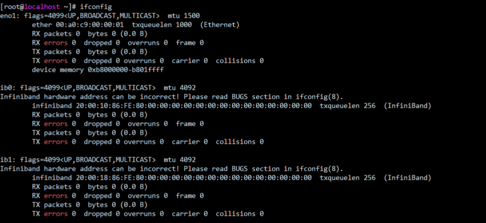
(3) Execute the ifconfig - a command to view the two IPoIB ports of the network adapter. The port names are displayed in the form of ibX. If both ports are displayed, the ports of the network adapter have been properly identified, as shown in Figure 5-3. If the ports are not identified, install the latest driver by referring to "5.3 Installing and removing a network adapter driver in the operating system", and identify the ports again.
Figure 5-3 Viewing the IPoIB ports of the network adapter
5.2.2 Windows Operating Systems
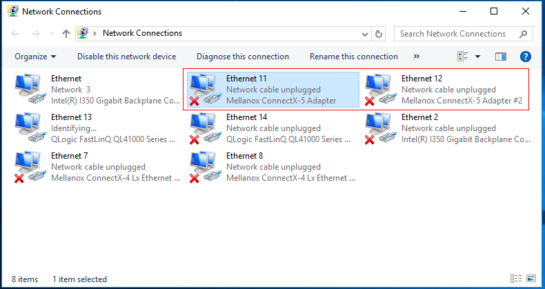
(1) As shown in Figure 5-4, open the Network Connections window and verify that the Mellanox ConnectX-5 network adapter is displayed, indicating that the IB1040i is properly recognized.
Figure 5-4 Viewing the network adapters
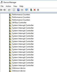
(2) If the network adapter is not displayed, open Device Manager, and check whether an unknown device exists in the Network adapters > Other devices window, as shown in Figure 5-5. In addition, check whether the PCIe ID of this device is consistent with that of the IB1040i. If the unknown device exists and its PCIe ID is consistent with that of the IB1040i, the driver is faulty. You need to install the latest driver by referring to "5.3 Installing and removing a network adapter driver in the operating system" and check whether the network adapter can be recognized again. If no unknown device exists, check whether the network adapter is properly installed.
Figure 5-5 Viewing device management
5.3 Installing and removing a network adapter driver in the operating system
The driver used by the IB1040i network adapter and the driver installation method vary according to the operating system. This section uses CentOS 7.5 and Windows Server 2016 as examples.
5.3.1 Linux Operating Systems
1. Checking the Current NIC Driver
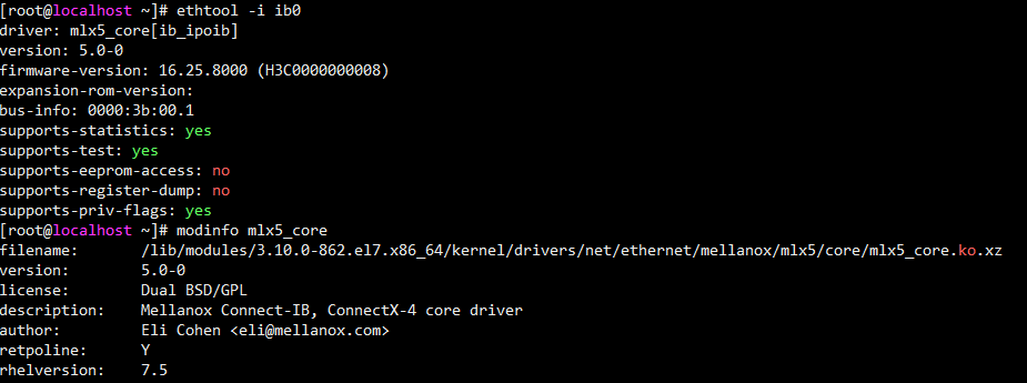
Execute the modinfo mlx5_core command to view the current driver version, as shown in Figure 5-6.
Figure 5-6 Checking the driver version
![]()
2. Installing the Driver
If the displayed driver is a .tgz file, perform the following steps:
(1) Copy the .tgz file (for example, MLNX_OFED_LINUX-4.6-1.0.1.1-rhel7.5-x86_64.tgz) to the system.
(2) Execute the tar -zxvf MLNX_OFED_XXX.tgz command to decompress the driver package.
(3) Execute the cd MLNX_OFED_LINUX-<ver> command to switch to the directory of the driver package.
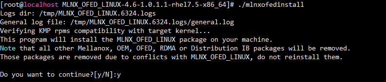
(4) Execute the ./mlnxofedinstall command to install the driver, as shown in Figure 5-7.
Figure 5-7 Installing the Driver
(5) After the installation finishes, restart the operating system or execute the rmmod mlx5_core and modprobe mlx5_core commands to reload the driver and make the driver take effect.
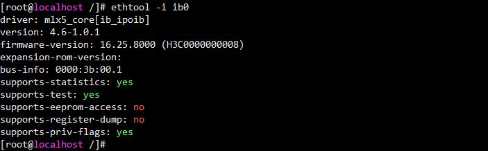
(6) Execute the modinfo mlx5_core or ethtool -i ibX command to verify that the driver version is correct, as shown in Figure 5-8. ibX in the command indicates the IPoIB port on the network adapter, and you can execute the ifconfig -a command to obtain the specific port name.
Figure 5-8 Verifying the driver version
3. Uninstalling the Driver
(1) Execute the ./uninstall.sh command under the directory of the driver installation package to remove the driver. Then, restart the operating system or execute the rmmod mlx5_core and modprobe mlx5_core commands to load the old driver.
5.3.2 Windows Operating Systems
1. Checking the Current NIC Driver
(1) Click the Windows button to enter the Start menu.
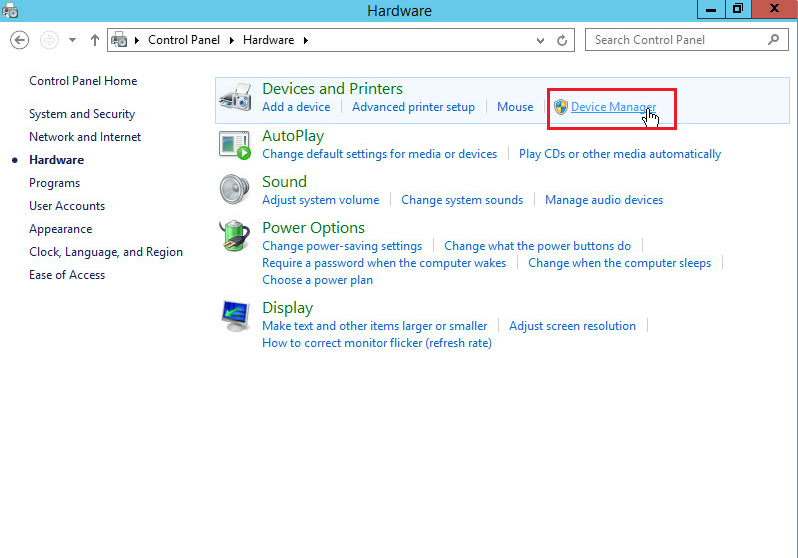
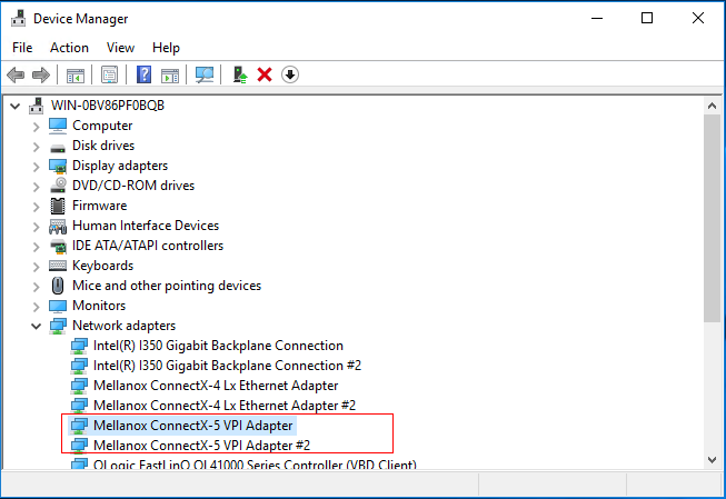
(2) Click Control Panel > Hardware > Device Manager to access Device Manager, as shown in Figure 5-9.
Figure 5-9 Accessing Device Manager
(3) On the interface shown in Figure 5-10, right-click the port of the network adapter, and then select Properties > Driver to view the driver information of the network adapter.
2. Installing the Driver
(1) Obtain the relevant driver from H3C website.
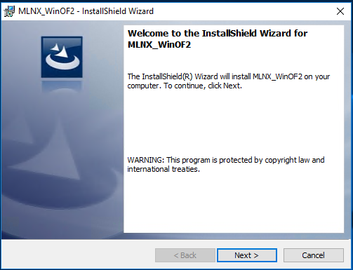
(2) As shown in Figure 5-11, double-click the driver and then click Next to install the driver MLNX_WinOF2.
Figure 5-11 Installing the driver
(3) After the installation is complete, reboot the system to make the driver take effect.
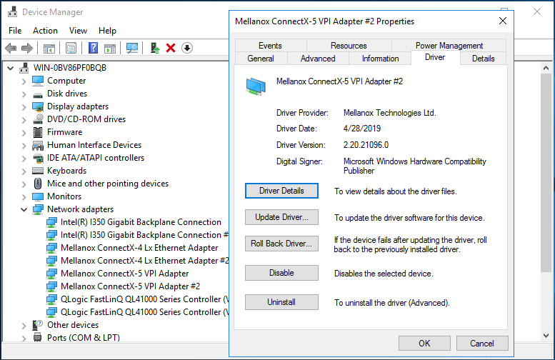
(4) As shown in Figure 5-12, view the driver information of the network adapter, and verify that the driver version is updated.
Figure 5-12 Verifying the driver version
3. Uninstalling the Driver
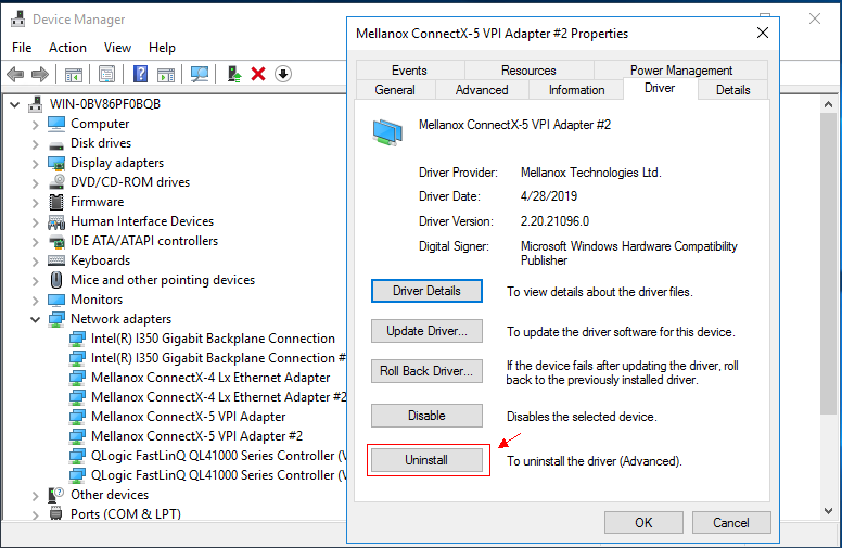
(1) Click the Windows button to enter the Start menu.
(2) Choose Control Panel > Hardware > Device Manager to access Device Manager.
(3) Right-click the NIC from which you want to uninstall the driver, select the Properties/Driver tab, and click the Uninstall button, as shown in Figure 5-13.
Figure 5-13 Uninstalling the Driver
5.4 Changing the network adapter mode
You can change the network adapter mode in the BIOS.
(1) Enter the BIOS Setup utility.
During the server boot process, press Delete or Esc when prompted to enter the BIOS Setup interface.
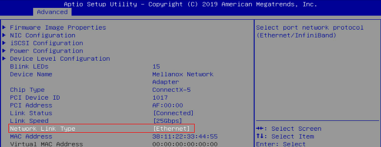
(2) Click the Advanced tab, select Device Level Configuration > Network Link Type, press Enter, and set the network link type to Ethernet or InfiniBand, as shown in Figure 5-14
Figure 5-14 Changing the network adapter mode
5.5 Configuring IB network properties
5.5.1 Running the OpenSM in the Linux operating system
(1) Execute the service opensm start or /etc/init.d/opensmd start command to start the OpenSM.
Figure 5-15 Starting the OpenSM
![]()
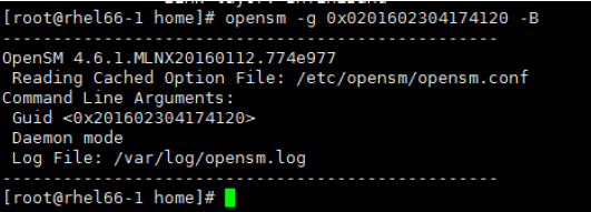
(2) By default, the first port is selected as the OpenSM management port. Alternatively, execute the opensm -g GUID -B -p [0-14] command to specify the OpenSM management port based on the GUID of the port. In this command, -g indicates that the OpenSM is bound to the port with the specified GUID (you can execute the ibstat command to query the GUID of the port), -B indicates that the OpenSM runs in the background, and -p indicates the priority (a larger number indicates a higher priority).
Figure 5-16 Using a command to specify the OpenSM management port
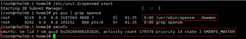
(3) As shown in the figure below, execute the ps aux | grep opensmand sminfo commands to check whether the OpenSM runs successfully in the local process and network. If the process exists and the OpenSM management port has been specified, the OpenSM runs successfully.
Figure 5-17 Checking the OpenSM running status
5.5.2 Configuring IPoIB
This section uses RHEL 7.5 as an example. To configure an IP address for the IPoIB port:
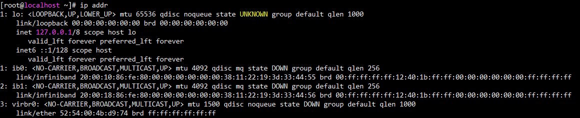
(1) As shown in the figure below, execute the ip addr command to view the IPoIB port information.
Figure 5-18 Viewing the IPoIB port information
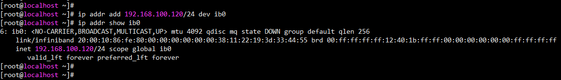
(2) As shown in the figure below, execute the ip addr add <IP>/<netmask> dev ibX command to configure a dynamic IP address.
Figure 5-19 Configuring a dynamic IP address
(3) Configure a static IP address. Switch to the /etc/sysconf/network-scripts directory and add the ifcfg-ibX configuration file. The format of the configuration file is shown below. You can adjust parameters based on actual requirements. After the configuration is completed, execute the service network restart command to restart the network service and activate the port.
DEVICE=ibx
TYPE=InfiniBand
ONBOOT=yes
IPADDR=172.168.100.100
NETMASK=255.255.255.0
GATEWAY=172.168.100.1
NM_CONTROLLED=no
USERCTL=no
BOOTPROTO=static
2. Configuring bonding of the IPoIB port
You can configure bonding for the IPoIB port of the IB1040i network adapter. This section takes RHEL7.5 as an example. In the Linux operating system, the port bonding configuration is implemented by the OS configuration file, and only the active-backup mode is supported. To configure bonding of the IPoIB port:
(1) Execute the ifconfig -a or ip addr command to locate the IPoIB port ibX of the IB1040i.
(2) Under the /etc/sysconf/network-scripts directory, create or update the ifcfg-ibX file. The content of the file is shown below, where MASTER indicates the name of the bonding interface. You can adjust parameters based on actual requirements.
DEVICE=ibX
ONBOOT=yes
BOOTPROTO=none
USERCTL=no
IPV6INIT=no
NM_CONTROLLED=no
MASTER=bond0
SLAVE=yes
TYPE=InfiniBand
PRIMARY=yes
(3) Under the /etc/sysconf/network-scripts directory, create ifcfg-bond0. Ensure that the device name is consistent with the value of MASTER in the previous step. The content is shown below, where BONDING_ OPTS is the bonding parameter setting, mode=1 indicates the active-standby mode, and primary indicates the primary interface.
DEVICE=bond0
IPADDR=192.168.72.54
NETMASK=255.255.255.0
NETWORK=192.168.72.0
BROADCAST=192.168.72.255
ONBOOT=yes
BOOTPROTO=none
USERCTL=no
NM_CONTROLLED=no
TYPE=Bonding
MTU=65520
BONDING_OPTS="miimon=100 mode=1 primary=ib0 updelay=0 downdelay=0"
BONDING_SLAVE0=ib0
BONDING_SLAVE1=ib1
![]() Note
Note
When the IPoIB-enabled IB1040i network adapter works in Connected mode, the MTU value in the configuration file cannot be greater than 65,520. When the IPoIB-enabled IB1040i network adapter works in Datagram mode, the MTU value in the configuration file cannot be greater than 2044. You can execute the cat/sys/class/net/ibX/mode command to query the working mode of the IB1040i network adapter.
(4) Edit the /etc/modprobe.d/ib_ Ipoib.conf configuration file. If the file does not exist, create the file first. Add the following content at the end of the file, where mode (bonding mode) can only be set to 1 (active-backup mode).
alias bond0 bonding
options bond0 miimon=100 mode=1 max_bonds=2
(5) Execute the service network restart or /etc/init.d/network restart command to restart the network and complete bonding.
5.6 Configuring Ethernet properties
5.7 Configuring PXE
![]() Note
Note
· This section describes how to enable PXE on a network adapter in the BIOS. To use the PXE feature, you must set up a PXE server. You can obtain the method for setting up a PXE server from the Internet.
(1) Enter the BIOS Setup utility.
During the server boot process, press Delete or Esc when prompted to enter the BIOS Setup interface.
(2) Enable PXE.
· Enabling PXE in UEFI mode
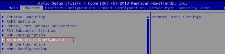
a. As shown in Figure 5-20, click the Advanced tab, select Network Stack Configuration, and then press Enter
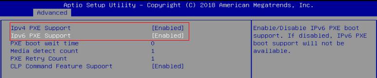
b. As shown in Figure 5-21, Set Ipv4 PXE Support and Ipv6 PXE Support to Enabled.
Figure 5-21 Enabling PXE in UEFI mode
· PXE is enabled in UEFI mode by default. To enable PXE in Legacy mode on the network adapter, configure as follows:
a. Select Advanced > Network Adapter > NIC Configuration, and press Enter.
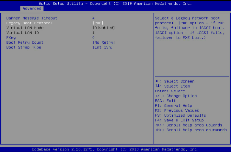
b. Set Legacy Boot Protocol to PXE, as shown in Figure 5-22.
Figure 5-22 Set Legacy Boot Protocol to PXE.
(3) Save the modification and restart the server.
Press F4 to save the configuration. The server restarts automatically. During startup, press F12 at the POST phase to boot the server from PXE.
5.8 Configuring iSCSI
![]() Note
Note
The iSCSI feature must be used with a remote network storage device. The methods for configuring network storage devices vary by device. For more information, see the related document of the storage device. This document describes only configuration on the local server.
This section takes the Windows Server 2016 and RHEL 7.5 operating systems as examples to describe how to configure iSCSI SAN when the IB1040i network adapter is connected to the ICM.
1. Configuring iSCSI SAN in the Windows operating system
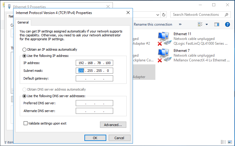
(1) As shown in Figure 5-23, configure an IP address for the network interface on the network adapter that connects to the iSCSI network storage device. Make sure the blade server can communicate with the iSCSI storage device properly.
Figure 5-23 Configuring the local IP address
(2) Enable and configure iSCSI.
a. As shown in Figure 5-24, open Control Panel, and then click iSCSI Initiator. Click OK on the dialog box that appears.
Figure 5-24 Clicking iSCSI Initiator

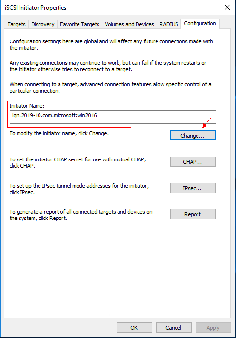
b. On the interface shown in Figure 5-25, click the Configuration tab, click Change, and then configure the name of the local iSCSI initiator.
Figure 5-25 Configuring the name of the iSCSI initiator
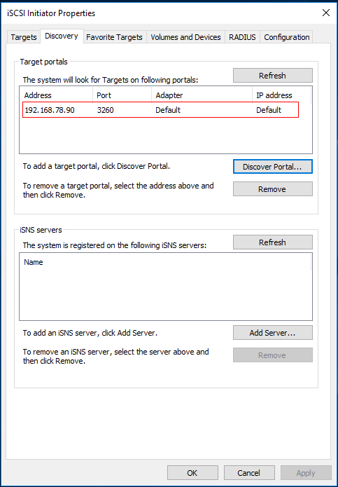
c. As shown in Figure 5-26, click the Discovery tab and click Discover Portals to add the address information of the peer device (network storage device).
Figure 5-26 Adding the address information of the peer device
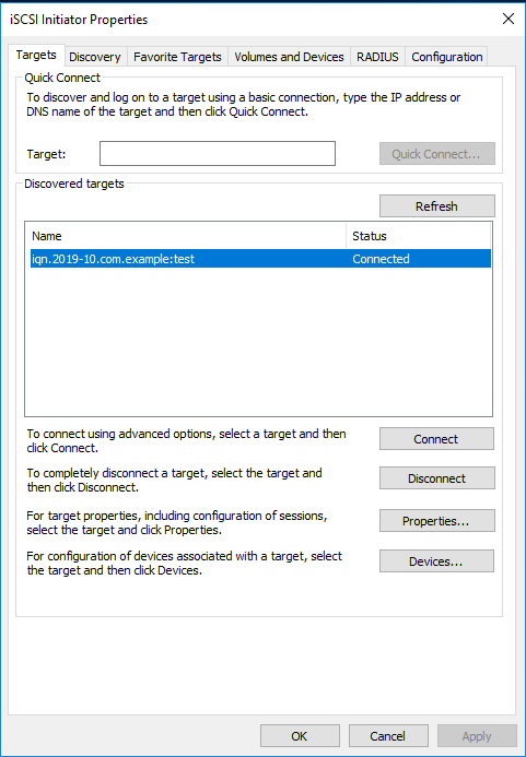
d. As shown in Figure 5-27, click the Targets tab. Click Connect to change the target status to Connected. Close the dialog box.
Figure 5-27 Connecting the target
(3) Add the network disk.
![]() Note
Note
Before adding the network disk, make sure the related configuration has been completed on the network storage device.
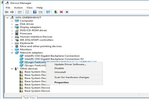
a. Open Control Panel, and then select Hardware > Device Manager > Network adapters. Right click the iSCSI network adapter under Storage controllers, and then select Scan for hardware changes, as shown in Figure 5-28.
Figure 5-28 Scanning the iSCSI network storage device
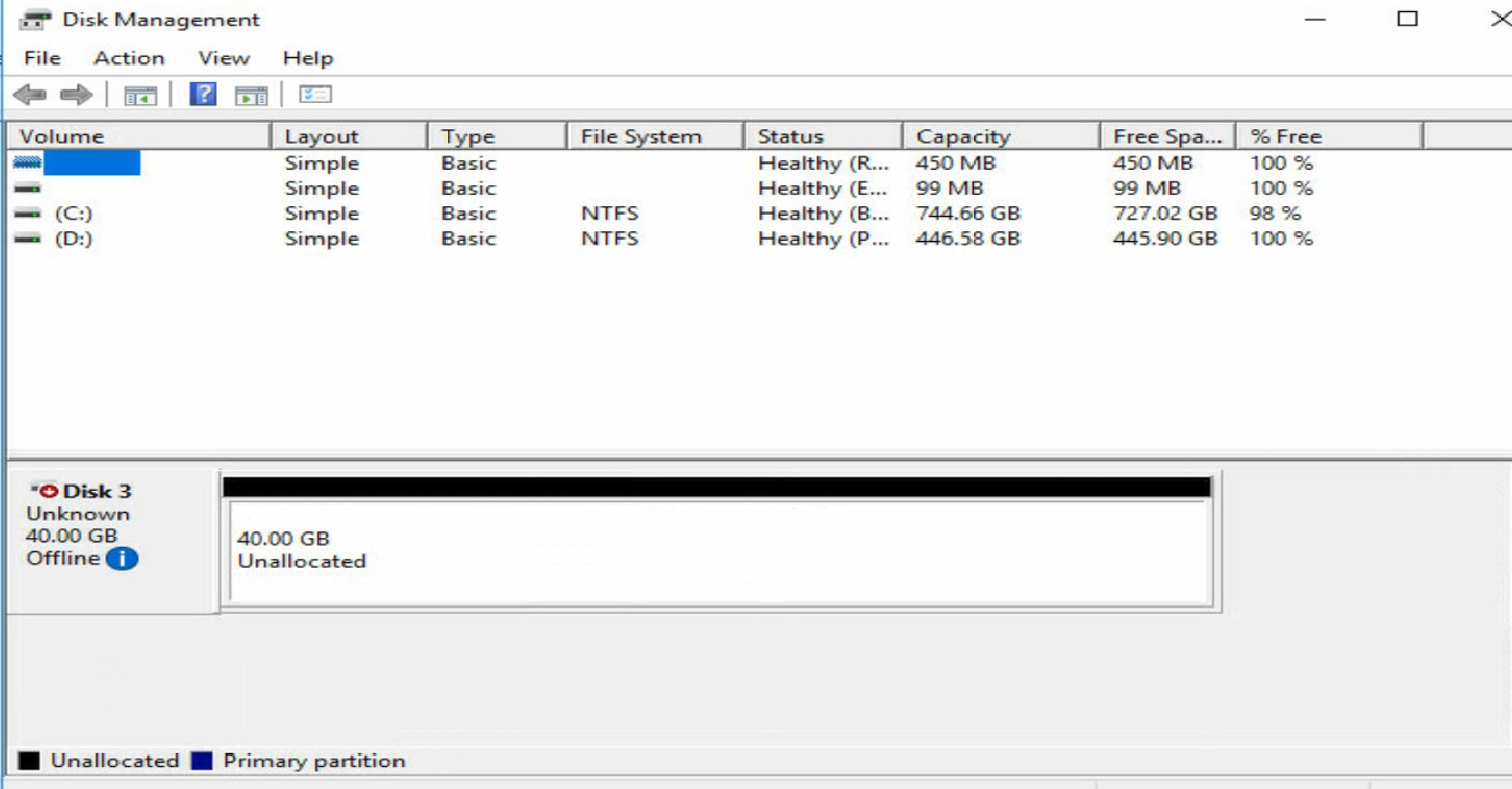
b. Right-click the Windows icon at the bottom left corner of the system, and open Disk Management. You can see a new disk with "Unknown" status, as shown in Figure 5-29.
Figure 5-29 Disk Management interface
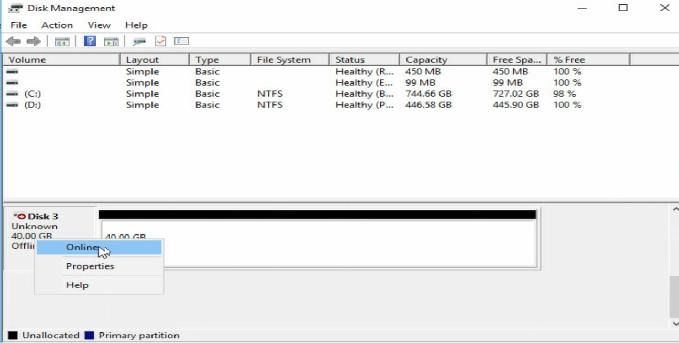
c. As shown in Figure 5-30, right-click the disk name and select Online to bring the disk online.
Figure 5-30 Bringing the disk online
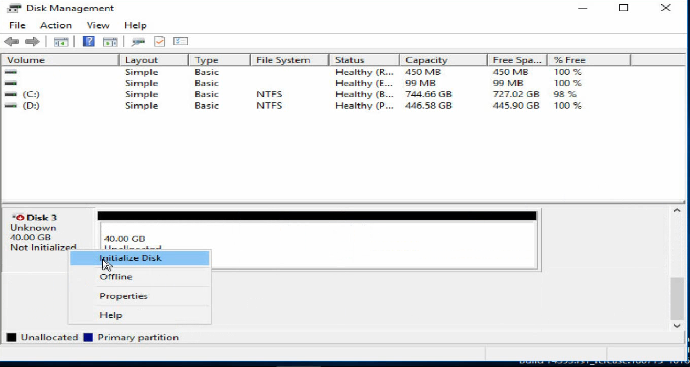
d. As shown in Figure 5-31, right-click the disk name again and select Initialize Disk to initialize the disk.
Figure 5-31 Initializing the disk
e. As shown in Figure 5-32, right-click the Unallocated area of the disk and split the disk as prompted.
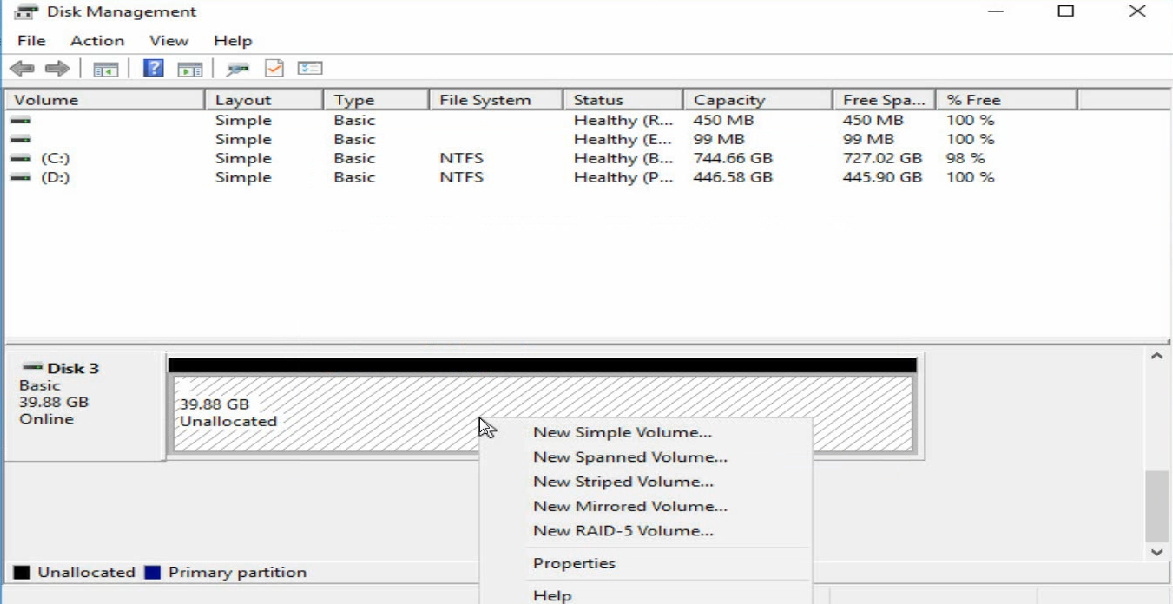
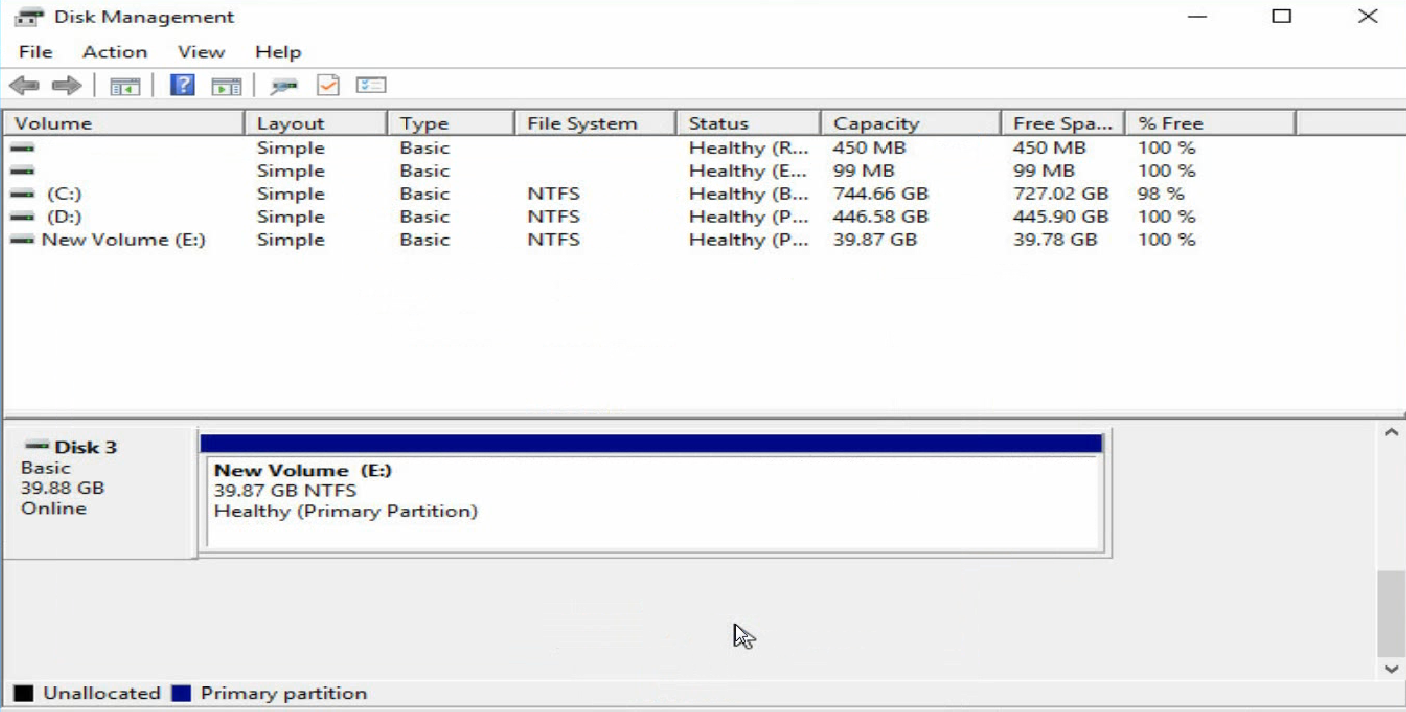
f. When volume-splitting is complete, the disk status is as shown Figure 5-33.
Figure 5-33 Volume-splitting is completed
(4) As shown in Figure 5-34, open My Computer to verify that the new volume has been added.
Figure 5-34 Identifying the network disk

2. Configuring iSCSI SAN in the Red Hat operating system
![]() Note
Note
Before configuring iSCSI SAN, make sure the iSCSI client software package has been installed on the server.
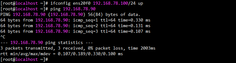
(1) As shown in Figure 5-35, configure an IP address for the network interface on the network adapter that connects to the iSCSI network storage device. Make sure the blade server can communicate with the iSCSI storage device properly.
Figure 5-35 Configuring the local IP address
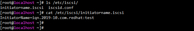
(2) As shown in Figure 5-36, execute the cat initiatorname.iscsi command in the /etc/iscsi directory to view the IQN of the local iSCSI initiator. If no IQN is specified, use the vi command to specify one manually.
Figure 5-36 Configuring the name of the local iSCSI initiator
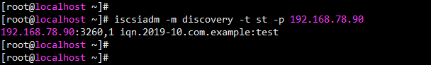
(3) As shown in Figure 5-37, execute the iscsiadm -m -discovery -t st -p target-ip command to probe the IQN of the iSCSI target (peer iSCSI storage device). The target-ip argument represents the IP address of the peer iSCSI storage device. Note that before performing this operation, you must ensure that the target of the storage server allows login and access of this initiator.
Figure 5-37 Probing the IQN of the iSCSI target
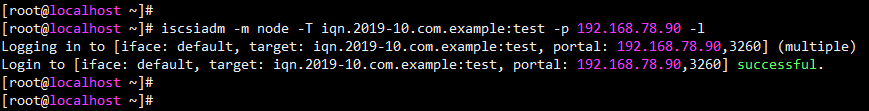
(4) As shown in Figure 5-38, execute the iscsiadm -m node -T iqn-name -p target-ip -l command to connect the iSCSI target. The iqn-name argument represents the IQN of the iSCSI target. The target-ip argument represents the IP address of the iSCSI target.
![]() Note
Note
· To disconnect the iSCSI target, execute the following command:
iscsiadm -m node -T iqn-name -p target-ip -u
· To delete the iSCSI target node information, execute the following command:
iscsiadm -m node -o delete -T iqn-name -p target-ip
Figure 5-38 Connecting the iSCSI target
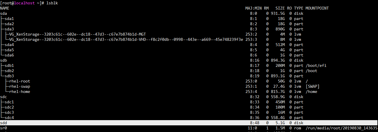
(5) As shown in Figure 5-39, execute the lsblk command to view the newly-added network disk.
![]() Note
Note
· Before adding the network disk, make sure the related configuration has been completed on the network storage device.
· In this example, one volume has been created on the storage server. So one network disk is added.
Figure 5-39 Viewing the newly-added network disk
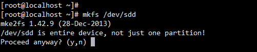
(6) As shown in Figure 5-40, execute the mkfs command to format the newly-added network disk.
Figure 5-40 Formatting a newly-added disk
(7) As shown in Figure 5-41, execute the mount command to mount the disk.
5.9 Configuration SR-IOV
1. Enabling SR-IOV
(1) Enter the BIOS Setup utility.
(2) As shown in Figure 5-42, click the Advanced tab, select PCI Subsystem Settings, and then press Enter
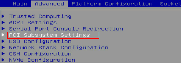
(3) On the interface shown in Figure 5-43, select SR-IOV Support and set it to Enabled. Press ESC until the system returns to the BIOS Setup main screen.
Figure 5-43 Setting SR-IOV Support to Enabled

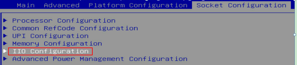
(4) As shown in Figure 5-44, click the Socket Configuration tab, and select IIO Configuration > Intel@ VT for Directed I/O (VT-d), and then press Enter.
Figure 5-44 Socket Configuration interface
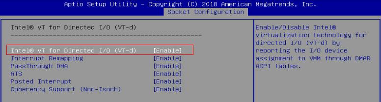
(5) On the interface shown in Figure 5-45, select Intel@ VT for Directed I/O (VT-d) and set it to Enable. Press ESC until the system returns to the BIOS Setup main screen.
Figure 5-45 Setting Intel@ VT for Directed I/O (VT-d) to Enable
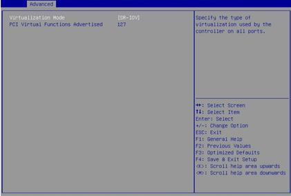
(6) As shown in Figure 5-46, click the Advanced tab, select either of the two ports of the IB1040i network adapter, and press Enter. Select Device Level Configuration and set Virtualization Mode of the two ports to SR-IOV, and configure PCI Virtual Functions Advertised that indicates the maximum number of VFs supported. Save the modification and restart the server.
Figure 5-46 Setting Virtualization Mode
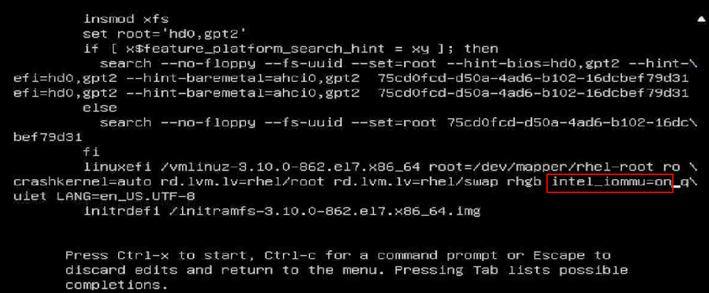
(7) During startup, press E to enter the interface shown in Figure 5-47. Press the arrow keys to turn pages. Add intel_iommu=on to the specified position to enable IOMMU. Press Ctrl-x to continue to start the server.
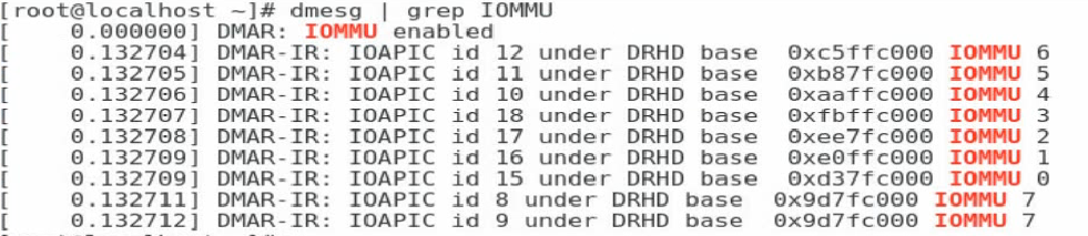
(8) As shown in Figure 5-48, after you enter the operating system, execute the dmesg | grep IOMMU command to verify that IOMMU is enabled.
Figure 5-48 Verifying that IOMMU is enabled
2. Configuring VFs in InfiniBand mode of the network adapter
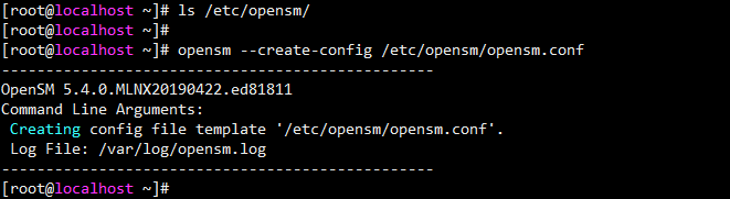
(1) Check the OpenSM configuration file /etc/opensm/opensm.conf, and verify that virtualization is enabled for the OpenSM. Figure 5-49 shows the content of the configuration file, where Virtualization support is enabled by default. If this configuration file is unavailable in the system directory, execute the opensm --create-config /etc/opensm/opensm.conf command to create one.
Figure 5-49 OpenSM configuration file
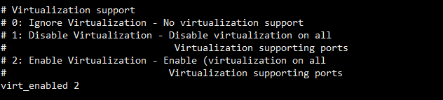
Figure 5-50 Creating an OpenSM configuration file
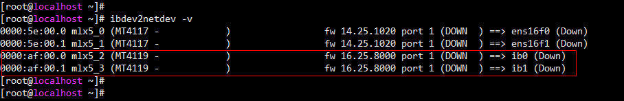
(2) Query the name of the device where SR-IOV needs to be enabled, and execute the ibdev2netdev -v command. As shown in Figure 5-51, the two lines of MT4119 devices are the two ports of the IB1040i network adapter.
Figure 5-51 Querying the device name
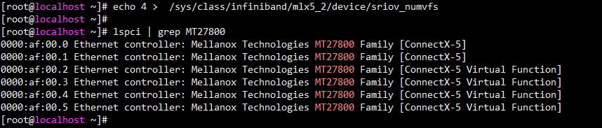
(3) Execute the echo NUM > /sys/class/infiniband/mlx5_X/device/sriov_numvfs command to assign a specified number of VFs to a PF port. The NUM argument represents the number of VFs to be assigned, and mlx5_X represents the PF device name. You can execute the lspci | grep MT27800 command to verify whether the VFs are successfully assigned.
Figure 5-52 Assigning VFs
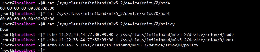
(4) Execute the following commands to configure the node GUID, port GUID, and policy of the VF. The specific parameter values are subject to the actual situation.
echo 11:22:33:44:77:66:88:90 > /sys/class/infiniband/mlx5_2/device/sriov/0/node
echo 11:22:33:44:77:66:88:90 > /sys/class/infiniband/mlx5_2/device/sriov/0/port
echo Follow > /sys/class/infiniband/mlx5_2/device/sriov/0/policy
Figure 5-53 Configuring the GUID and policy of the VF
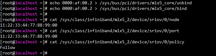
(5) As shown in Figure 5-54, rebind the VF port to make the configuration effective. To assign the VF to a VM, make sure that the host driver does not use the VF. That is, you must first unbind the host and then assign the VF to the VM.
Figure 5-54 Rebinding the VF port
3. Configuring VFs in Ethernet mode of the network adapter
(1) As shown in Figure 5-55, execute the echo NUM > /sys/class/net/ethX/device/sriov_numvfs command to assign a specified number of VFs to a PF port. The NUM argument represents the number of VFs to be assigned, and ethX represents the PF port name. You can execute the lspci | grep MT27800 command to verify whether the VFs are successfully assigned.
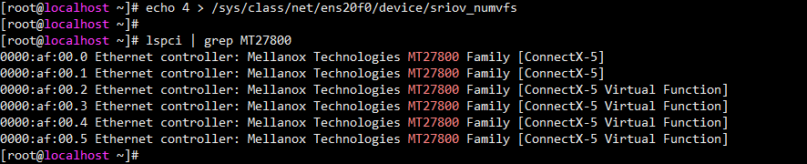
(2) To modify the MAC address for the VF, execute the ip link set ethVF vf 0 mac MAC address command.
4. Adding VFs to a VM
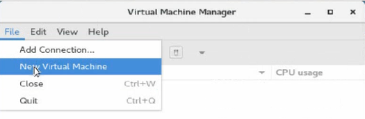
(1) As shown in Figure 5-56, execute the virt-manager command to run the VM manager, and select File > New Virtual Machine to create a VM.
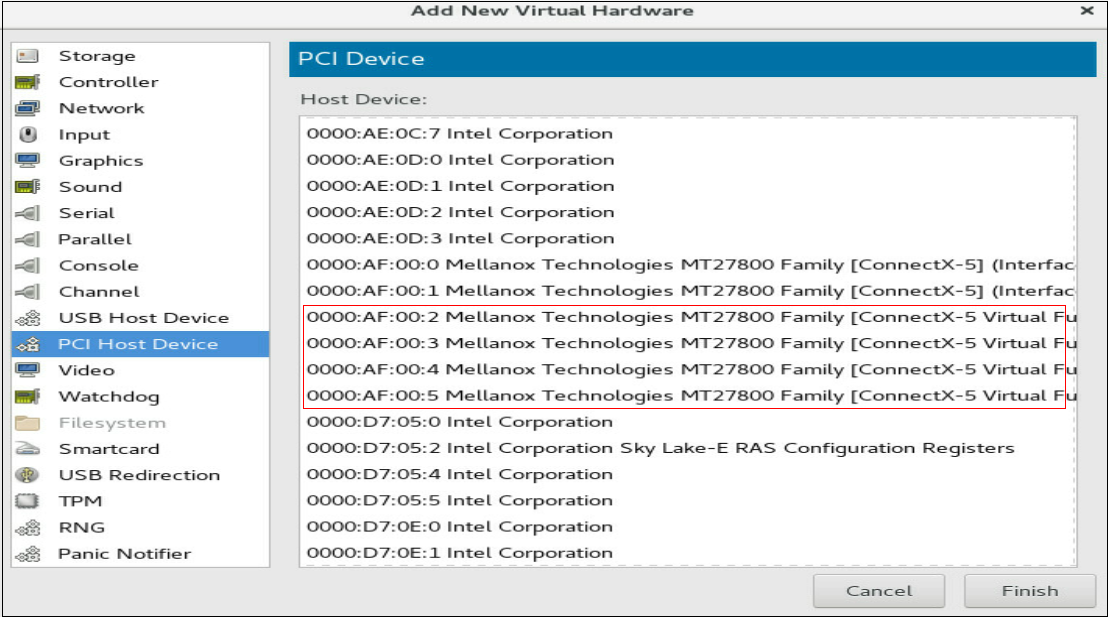
(2) On the interface of the new VM, add a virtual NIC as instructed by the callouts in Figure 5-57.
Figure 5-57 Adding a virtual NIC
(3) Install the vNIC driver and execute the ifconfig ethVF hw ether xx:xx:xx:xx:xx:xx command to configure an MAC address for the vNIC. The ethVF argument represents the virtual NIC name. The xx:xx:xx:xx:xx:xx argument represents the MAC address.
5.10 Configuring advanced features
1. 802.1Q VLAN
This
section uses RHEL 7.5 as an example.
To configure 802.1Q VLAN in the operating system:
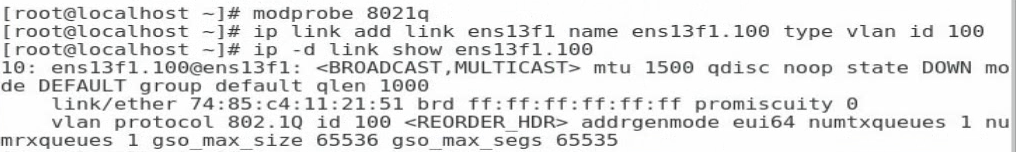
(1) Execute the modprobe 8021q command to load the 802.1Q module.
(2) Execute the ip link add link ethX name ethX.id type vlan id id command to create a VLAN interface on a physical port. The ethX argument represents the physical port name. The id argument represents the VLAN ID.
(3) Execute the ip -d link show ethX.id command to verify that the VLAN interface has been created successfully, as shown in Figure 5-58.
Figure 5-58 Creating a VLAN interface
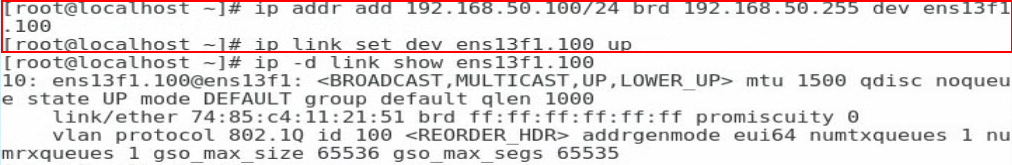
(4) Execute the ip addr add ipaddr/mask brd brdaddr dev ethX.id and ip link set dev ethX.id up commands to assign an IP address to the VLAN interface and set the VLAN interface state to UP, respectively. The ipaddr/mask argument represents the IP address and mask of the VLAN interface. The brdaddr argument represents the broadcast address. The ethX.id argument represents the name of the VLAN interface, as shown in Figure 5-59.
![]() Note
Note
To delete a VLAN interface, execute the ip link set dev ethX.id down and ip link delete ethX.id commands.
Figure 5-59 Assigning an IP address to the VLAN interface and set the VLAN interface state to UP
5.10.2 Bonding (Linux)
This section uses RHEL 7.5 as an example to
describes how to configure bonding in mode 6.
To configure bonding in mode 6:
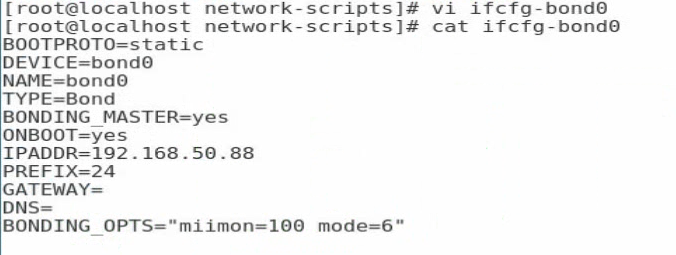
(1) Execute the vi ifcfg-bond0 command in the /etc/sysconfig/network-scripts/ directory to create a configuration file for bond0 and add the following information:
BOOTPROTO=static
DEVICE=bond0
NAME=bond0
TYPE=Bond
BONDING_MASTER=yes
ONBOOT=yes
IPADDR=192.168.50.88//Configure the interface IP address for bond0
PREFIX=24//Configure the subnet mask
GATEWAY=
DNS=
BONDING_OPTS=”miimon=100 mode=6”//Set the detection interval to 100 ms and the bonding mode to 6
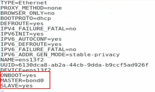
(2) Edit the configuration file for a slave interface. As shown in Figure 5-61, execute the vi ifcfg-ethX command and add the following information to the configuration file:
ONBOOT=yes
MASTER=bond0
SLAVE=yes
For other slave interfaces to be added to bond0, repeat this step.
Figure 5-61 Editing the configuration file for a slave interface
(3) Execute the service network restart command to restart the network service and have bond0 take effect.
Figure 5-62 Restarting the network service
![]()
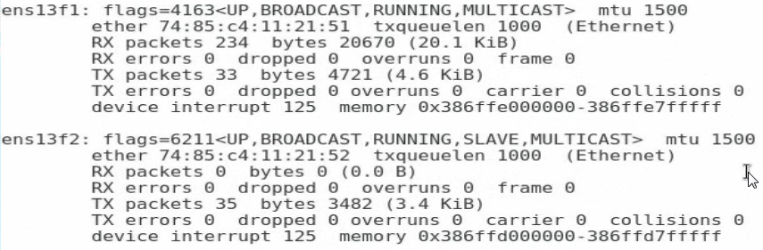
(4) Execute the cat /proc/net/bonding/bond0 command to view information about bond0 and network adapter. In this example, bond0 and the two slave interfaces are in all in UP state.
Figure 5-63 Viewing information about bond0
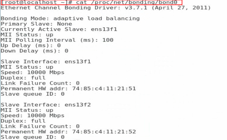
Figure 5-64 Viewing information about the network adapter (1)
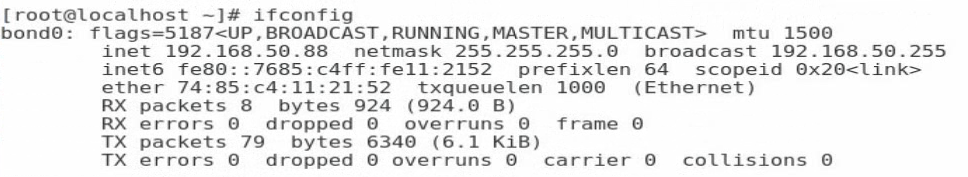
Figure 5-65 Viewing information about the network adapter (2)
5.10.3 Teaming (Windows)
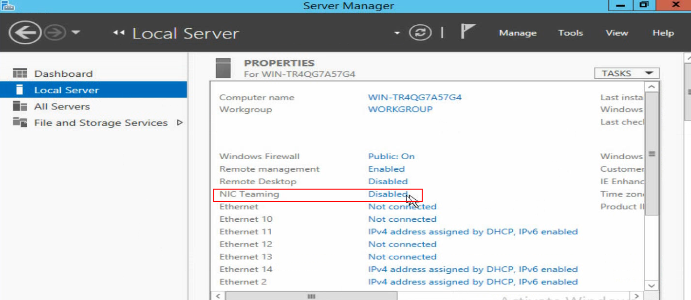
(1) As shown in Figure 5-66, open Server Manager, and then select Local Server > NIC Teaming > Disabled to enter the NIC Teaming page.
Figure 5-66 Entering the NIC Teaming page
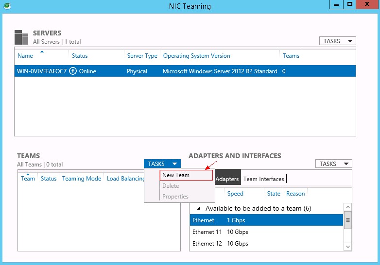
(2) As shown in Figure 5-67, select TASKS > New Team to create a team.
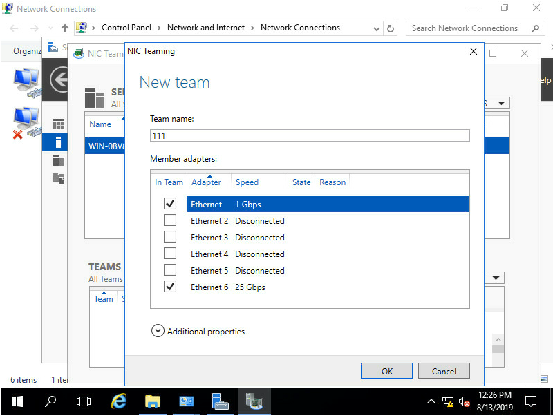
(3) As shown in Figure 5-68, configure the team name and select the network adapters to be added to the team. Select Additional properties, configure the properties, and then click OK.
![]() Tip
Tip
It takes a long time to create a team in Switch Independent mode.
Figure 5-68 Configuring a new team
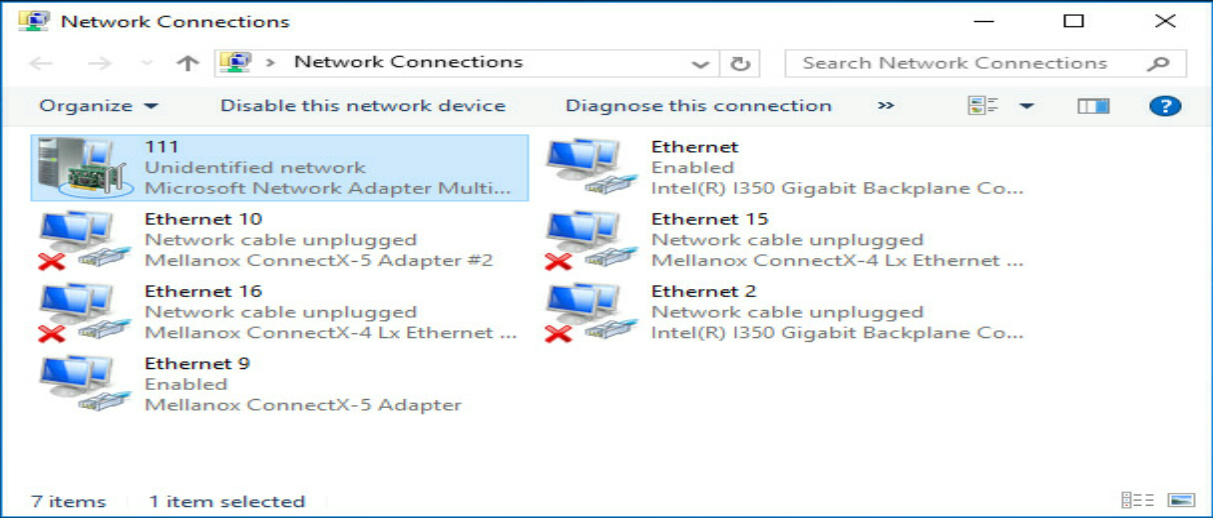
(4) As shown in Figure 5-69, after team creation finishes, you can view the network adapter 111 on the Network Connections page.
Figure 5-69 Viewing the new network adapter
5.10.4 TCP offloading
Offloading is to move some data processing load (such as segmentation and reassembly) of the operating system to the network adapter hardware, so as to reduce the system CPU consumption and improve the processing performance. TCP offloading includes TCP Segmentation Offload (TSO), Large Segment Offload (LSO), Large Receive Offload (LRO), Generic Segmentation Offload (GSO), and Generic Receive Offload (GRO).
TSO, as its name implies, is used to segment TCP packets. TSO is also called LSO/LRO, which corresponds to offloading in two directions. When the transmitted data exceeds the MTU limit, the operating system only needs to submit a transmission request to the network adapter once. The network adapter automatically segments and encapsulates the data before sending it. When a lot of fragmented packets are received, LRO automatically reassembles them into a larger segment of data and submits it to the operating system for processing at a time.
In practice, GSO/GRO is more frequently used, and can automatically detect the features supported by the network adapter. If the network adapter supports segmentation, GSO/GRO directly sends data to the network adapter. Otherwise, GSO/GRO sends data to the network adapter after segmentation.
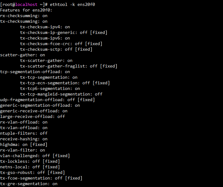
(1) As shown in Figure 5-70, execute the ethtool -k ethx command to check whether the offload features are supported and enabled on the network adapter. The ethx argument represents the port name of the network adapter.
Figure 5-70 Checking whether the offload features are supported and enabled on the network adapter
(2) As shown in Figure 5-71, execute the ethtool -K ethX feature on/off command to enable or disable an offload feature. The ethx argument represents the port name of the network adapter. The feature argument represents the offload feature name, and its value includes tso, lso, lro, gso, and gro.
Figure 5-71 Configuring the offload features
![]()
6 Acronyms and Abbreviations
Table 6-1 Acronyms and Abbreviations
|
Acronyms and Abbreviations |
Explanation |
|
F |
|
|
FC |
Fiber Channel |
|
FCoE |
Fiber Channel Over Ethernet |
|
H |
|
|
HCA |
Host Channel Adapter |
|
I |
|
|
InfiniBand |
|
|
IPoIB |
IP over InfiniBand |
|
iSCSI |
Internet Small Computer System Interface |
|
N |
|
|
NCSI |
Network Controller Sideband Interface |
|
NPAR |
NIC Partitioning |
|
P |
|
|
PCIe |
Peripheral Component Interconnect Express |
|
PF |
Physical Function |
|
PXE |
Preboot Execute Environment |
|
R |
|
|
RDMA |
Remote Direct Memory Access |
|
S |
|
|
SAN |
Storage Area Network |
|
SM |
Subnet Manager |
|
SR-IOV |
Single Root I/O Virtualization |
|
T |
|
|
TCP |
Transmission Control Protocol |
|
V |
|
|
VF |
Virtual Function |
|
Virtual Machine Data Queue |
|