- Table of Contents
- Related Documents
-
| Title | Size | Download |
|---|---|---|
| 02-WT configuration | 216.15 KB |
Contents
About the wireless terminator solution
Application scenarios and advantages
Restrictions: Hardware compatibility with WT
Restrictions and guidelines: WT configuration
Configuring PoE for a WTU port
Display and maintenance commands for WTs
Example: Configuring the wireless terminator solution by using the basic networking scheme
Example: Configuring the wireless terminator solution by using the cascade networking scheme
Configuring WTs
Support for the IoT capability depends on the WT model.
This chapter contains basic WT configuration. For information about IoT configuration, see IoT AP configuration in Internet of Things Configuration Guide.
You can configure 2 × 2 MIMO on some WTUs, but the configuration will not take effect.
About the wireless terminator solution
The wireless terminator solution is a new-generation wireless network structure proposed for large scale and intensive deployment of WLANs at a low cost.
Network topology
Basic networking scheme
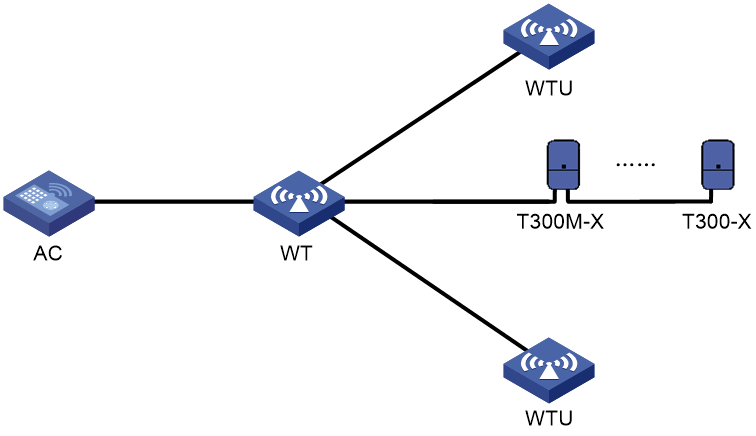
As shown in Figure 1, the basic network in a wireless terminator solution includes the following entities:
· Wireless terminator—A WT is an AP that associates with the AC on behalf of WTUs and uses wired cables to connect to IoT modules. It offers PoE power supply and data forwarding for the WTUs and IoT modules.
· Wireless terminator unit—A WTU is an indoor AP that only sends and receives wireless packets. A WTU supports 802.11ac Gigabit wireless access, and it can operate simultaneously in 2.4 GHz and 5 GHz bands.
· AC—Manages the WT, the WTUs, and the IoT modules.
· IoT module—An IoT module acts as a sensor to connect things to the Internet for intelligent identification, locating, tracking, monitoring, and management of the things.
Figure 1 Basic networking scheme of wireless terminator solution
Cascade networking scheme
|
|
NOTE: Support for the cascade networking scheme depends on the WT model. |
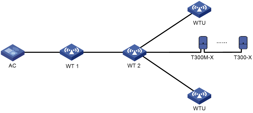
As shown in Figure 2, the cascade network in a wireless terminator solution includes the following entities:
· Wireless terminator 1—An AP that uses wired cables to connect to wireless terminator 2. It offers PoE power supply and data forwarding for wireless terminator 2.
· Wireless terminator 2—An AP that associates with the AC on behalf of WTUs and uses wired cables to connect to IoT modules. It offers PoE power supply and data forwarding for the WTUs and IoT modules.
· Wireless terminator unit—A WTU is an indoor AP that only sends and receives wireless packets. A WTU supports 802.11ac Gigabit wireless access, and it can operate simultaneously in 2.4 GHz and 5 GHz bands.
· AC—Manages the WT, the WTUs, and the IoT modules.
· IoT module—An IoT module acts as a sensor to connect things to the Internet for intelligent identification, locating, tracking, monitoring, and management of the things.
Figure 2 Cascade networking scheme of wireless terminator solution
Application scenarios and advantages
The wireless terminator solution can be widely applied to scenarios such as dormitories, apartments, hotels, small-sized offices, and medical institutions, and intelligent campus. This solution has the following advantages over traditional independent or indoor solutions:
· Cost saving and easy deployment—A WT and WTUs are connected through Ethernet cables instead of dedicated lines. The WT directly supplies power to the WTUs through PoE.
· Strong signal strength—Each room has dedicated bandwidth.
· Enhanced network performance and user experience—WTUs can offer high uplink bandwidth.
· Most up-to-date wireless access technology—WTUs support 802.11ac Gigabit and dual-band access.
· Support for IoT module connection—A WT can connect to IoT modules to provide more services besides wireless services, which is cost saving and easy to manage.
Restrictions: Hardware compatibility with WT
|
Hardware series |
Model |
Product code |
WT compatibility |
|
WX2500X series |
WX2560X WX2580X |
EWP-WX2560X EWP-WX2580X |
Yes |
|
Hardware series |
Model |
Product code |
WT compatibility |
|
WX2800X series |
WX2812X-PWR WX2860X WX2880X |
EWP-WX2812X-PWR EWP-WX2860X EWP-WX2880X |
No |
|
WSG1800X series |
WSG1812X-PWR WSG1840X |
EWP-WSG1812X-PWR EWP-WSG1840X |
No |
Restrictions and guidelines: WT configuration
You can configure APs by using the following methods:
· Configure APs one by one in AP view.
· Assign APs to an AP group and configure the AP group in AP group view.
· Configure all APs in global configuration view.
For an AP, the settings made in these views for the same parameter take effect in descending order of AP view, AP group view, and global configuration view.
WT tasks at a glance
To configure a WT, perform the following tasks:
· Configuring PoE for a WTU port
· Enabling port type switching
Configuring PoE for a WTU port
About this task
A WT uses WTU ports to supply power to its connected WTUs through PoE. For a WTU to operate correctly, make sure PoE is enabled for the WTU port that connects the WT to the WTU.
Procedure
1. Enter system view.
system-view
2. Enter AP view or an AP group's AP model view.
¡ Enter AP view.
wlan ap ap-name
¡ Execute the following commands in sequence to enter an AP group's AP model view:
wlan ap-group group-name
ap-model ap-model
The AP must be a WT.
3. Configure PoE for a WTU port.
poe wtu-port port-number1 [ to port-number2 ] { disable | enable }
By default:
¡ In AP view, an AP uses the configuration in an AP group's AP model view.
¡ In an AP group's AP model view, PoE is enabled for a WTU port.
Specifying the WT version
Restrictions and guidelines
If the specified WT version is different from the WT version in use, the WT will restart automatically. Then, it will switch to the specified WT version and restore the factory settings.
This command does not take effect on WTs that support different types of WTUs.
Procedure
1. Enter system view.
system-view
2. Enter AP view or an AP group's AP model view.
¡ Enter AP view.
wlan ap ap-name
¡ Execute the following commands in sequence to enter an AP group's AP model view:
wlan ap-group group-name
ap-model ap-model
The AP must be a WT.
3. Specify the WT version.
wt version { 1 | 2 | 3 }
By default:
¡ In AP view, an AP uses the configuration in an AP group's AP model view.
¡ In an AP group's AP model view, the WT version varies by AP model.
Support for this command depends on the WT model.
Enabling port type switching
About this task
You can switch an Ethernet port on a WT to a WTU port to increase the number of WTU ports or switch a WTU port to an Ethernet port.
If a port has a mark of two different port names separated by a slash (/), G3/WTU26 for example, the port supports port type switching
Restrictions and guidelines
|
|
CAUTION: To prevent the chips on the connected from being damaged because of PoE power supply capacity change, make sure the port to switch is not connected to any other device. |
This command will reboot the WT and the new port will use its default settings.
Procedure
1. Enter system view.
system-view
2. Enter AP view or an AP group's AP model view.
¡ Enter AP view.
wlan ap ap-name
¡ Execute the following commands in sequence to enter an AP group's AP model view:
wlan ap-group group-name
ap-model ap-model
The AP must be a WT.
3. Enable port type switching between an Ethernet port and a WTU port.
port-type switch number port-number-list { gigabitethernet | wtu }
By default:
¡ In AP view, an AP uses the configuration in an AP group's AP model view.
¡ In an AP group's AP model view, the default setting varies by WT model.
Support for this command depends on the WT model.
Display and maintenance commands for WTs
Execute display commands in any view.
|
Task |
Command |
|
Display WT information and information about the WTUs connected to it. |
display wlan wt { all | name wt-name } |
WT configuration examples
Example: Configuring the wireless terminator solution by using the basic networking scheme
Network configuration
As shown in Figure 3, construct a wireless network by using the basic networking scheme. WTUs WTU 1, WTU 2, WTU 3 are connected to WTU ports 1, 2, and 3 on the WT, respectively.

Procedure
# Create a WT named wt, and specify its model and serial ID.
<AC> system-view
[AC] wlan ap wt model WT1024-X-Q
[AC-wlan-ap-wt] serial-id 219801A0SS9156G00072
[AC-wlan-ap-wt] quit
# Create a WTU named wtu1, and specify its model and serial ID.
[AC] wlan ap wtu1 model WTU430
[AC-wlan-ap-wtu1] serial-id 219801A0SS9156G00185
[AC-wlan-ap-wtu1] quit
# Create a WTU named wtu2, and specify its model and serial ID.
[AC] wlan ap wtu2 model WTU430
[AC-wlan-ap-wtu2] serial-id 219801A0SS9156G00133
[AC-wlan-ap-wtu2] quit
# Create a WTU named wtu3, and specify its model and serial ID.
[AC] wlan ap wtu3 model WTU430
[AC-wlan-ap-wtu3] serial-id 219801A0SS9156G00054
[AC-wlan-ap-wtu3] quit
Verifying the configuration
# Verify that the WT and WTUs have come online.
<AC> display wlan wt all
WT name : wt
Model : WT1024-X-Q
Serial ID : 219801A0SS9156G00072
MAC address : 0000-f3ea-0a3e
WTU number : 3
Wireless Terminator Unit:
--------------------------------------------------------
WTU name Port Model Serial ID
---------------------------------------------------------
wtu1 1 WTU430 219801A0SS9156G00185
wtu2 2 WTU430 219801A0SS9156G00133
wtu3 3 WTU430 219801A0SS9156G00054
Example: Configuring the wireless terminator solution by using the cascade networking scheme
Network configuration
As shown in Figure 4, construct a wireless network by using the cascade networking scheme. WT 1 is connected to the AC through the switch, and WT 2 is connected to the WTU port of WT 1. WTU 1, WTU 2, and IoT module T300M-X are connected to the WTU ports on WT 2.

Procedure
# Create a WT named wt1, and specify its model and serial ID.
<AC> system-view
[AC] wlan ap wt1 model WT2024-U
[AC-wlan-ap-wt1] serial-id 219801A11WC17C000021
[AC-wlan-ap-wt1] quit
# Create a WT named wt2, and specify its model and serial ID.
[AC] wlan ap wt2 model WT1010-QU
[AC-wlan-ap-wt2] serial-id 219801A11VC17C000007
[AC-wlan-ap-wt2] quit
# Create a WTU named wtu1, and specify its model and serial ID.
[AC] wlan ap wtu1 model WTU430
[AC-wlan-ap-wtu1] serial-id 219801A0SS9156G00185
[AC-wlan-ap-wtu1] quit
# Create a WTU named wtu2, and specify its model and serial ID.
[AC] wlan ap wtu2 model WTU430
[AC-wlan-ap-wtu2] serial-id 219801A0SS9156G00133
[AC-wlan-ap-wtu2] quit
# Specify the serial number and type of IoT module T300M-X, and enable the IoT module.
[AC] wlan ap wt2
[AC-wlan-ap-wt2] module 1
[AC-wlan-ap-wt2-module-1] serial-number 219801A19A8171E00008
[AC-wlan-ap-wt2-module-1] type ble
[AC-wlan-ap-wt2-module-1] module enable
[AC-wlan-ap-wt2-module-1] quit
[AC-wlan-ap-wt2]
# Configure T300-X in the same way T300M-X is configured. (Details not shown.)
Verifying the configuration
# Display information about all APs on the AC.
<AC> display wlan ap all
Total number of APs: 4
Total number of connected APs: 4
Total number of connected manual APs: 4
Total number of connected auto APs: 0
Total number of connected common APs: 0
Total number of connected WTUs: 2
Total number of inside APs: 0
Maximum supported APs: 64
Remaining APs: 60
Total AP licenses: 128
Local AP licenses: 128
Server AP licenses: 0
Remaining local AP licenses: 127.5
Sync AP licenses: 0
AP information
State : I = Idle, J = Join, JA = JoinAck, IL = ImageLoad
C = Config, DC = DataCheck, R = Run, M = Master, B = Backup
AP name APID State Model Serial ID
wt1 1 R/M WT2024-U 219801A11WC17C000021
wt2 2 R/M WT1010-QU 219801A11VC17C000007
wtu1 3 R/M WTU430 219801A0SS9156G00185
wtu2 4 R/M WTU430 219801A0SS9156G00133
# Verify that the WTs and WTUs have come online.
<AC> display wlan wt all
WT name : wt2
Model : WT1010-QU
Serial ID : 219801A11VC17C000007
MAC address : e8f7-24cf-4550
WTU number : 2
Wireless Terminator Unit:
---------------------------------------------------------
WTU name Port Model Serial ID
---------------------------------------------------------
wtu1 1 WTU430 219801A0SS9156G00185
wtu2 2 WTU430 219801A0SS9156G00133
# Display information about all IoT modules.
<AC> display iot module all
AP name : wt2
AP model : WT1010-QU
Serial ID : 219801A11VC17C000007
MAC address : e8f7-24cf-4550
Modules : 3
Port ID: 5
-----------------------------------------------------------------------------
ModuleID Model SerialNumber H/W Ver S/W Ver LastRebootReason
-----------------------------------------------------------------------------
1 T300M-X 219801A19A8171E00008 Ver.A E1109 Power on
2 T300-X T3001234567898765432 Ver.A E1109 Power on
3 T300-X T3001234567898765434 Ver.A E1109 Power on
# Display information about IoT module 1 connected to WT 2.
<AC> display wlan module-information ap wt2 module 1
Module administrative type : BLE
Module physical type : H3C
Model : T300-B
HW version : Ver.A
SW version : E1109 V100R001B01D035
Serial ID : 219801A19C816C000012
Module MAC : d461-fefc-fff2
Module physical status : Normal
Module administrative status : Enabled
Description : Not configured