- Table of Contents
- Related Documents
-
| Title | Size | Download |
|---|---|---|
| 01-Hardware Information and Specifications | 1.28 MB |
1 Product models and technical specifications
Product models
The H3C S6890 Switch Series includes the following models:
|
Product code |
Product model |
|
LS-6890-54HF |
S6890-54HF |
|
LS-6890-30HF |
S6890-30HF |
|
LS-6890-44HF |
S6890-44HF |
Technical specifications
Table1-1 Technical specifications
|
Item |
S6890-54HF |
S6890-30HF |
S6890-44HF |
|
Dimensions (H × W × D) |
43.6 × 440 × 460 mm (1.72 × 17.32 × 18.11 in) |
43.6 × 440 × 460 mm (1.72 × 17.32 × 18.11 in) |
44× 440 × 460 mm (1.73 × 17.32 × 18.11 in) |
|
Weight |
≤ 13 kg (28.66 lb) |
≤ 10 kg (22.05 lb) |
≤ 10 kg (22.05 lb) |
|
Console port |
· 1 × mini USB console port · 1 × serial console port |
· 1 × mini USB console port · 1 × serial console port |
1 × serial console port |
|
Management Ethernet port |
· 1 × 10M/100M/1000M BASE-T copper port · 1 × SFP port |
· 1 × 10M/100M/1000M BASE-T copper port · 1 × SFP port |
2 × 10M/100M/1000M BASE-T copper ports |
|
USB port |
1 |
1 |
1 |
|
SFP+ port |
48 |
24 |
40 |
|
QSFP28 port |
6 |
6 |
4 |
|
SMB clock output port |
N/A |
N/A |
2 |
|
SMB clock input port |
N/A |
N/A |
2 |
|
1PPS/ToD time synchronization port |
N/A |
N/A |
2 |
|
Fan tray slots |
5 |
4 |
5 |
|
Power supply slots |
2 |
2 |
2 |
|
Minimum power consumption |
· Single AC input: 140 W · Single DC input: 135 W · Dual AC inputs: 155 W · Dual DC inputs: 148 W |
· Single AC input: 117 W · Single DC input: 112 W · Dual AC inputs: 122 W · Dual DC inputs: 117 W |
· Single AC input: 148 W · Single DC input: 151 W · Dual AC inputs: 159 W · Dual DC inputs: 159 W |
|
Maximum power consumption |
· Single AC input: 327 W · Single DC input: 320 W · Dual AC inputs: 340 W · Dual DC inputs: 330 W |
· Single AC input: 258 W · Single DC input: 249 W · Dual AC inputs: 260 W · Dual DC inputs: 247 W |
· Single AC input: 244 W · Single DC input: 250 W · Dual AC inputs: 249 W · Dual DC inputs: 255 W |
|
Chassis leakage current compliance |
· UL 60950-1 · EN 60950-1 · IEC 60950-1 · GB4943 |
· UL 60950-1 · EN 60950-1 · IEC 60950-1 · GB4943 |
· UL 60950-1 · EN 60950-1 · IEC 60950-1 · GB4943 |
|
Operating temperature |
0°C to 45°C (32°F to 113°F) |
0°C to 45°C (32°F to 113°F) |
0°C to 45°C (32°F to 113°F) |
|
Operating humidity |
5% RH to 95% RH, noncondensing |
5% RH to 95% RH, noncondensing |
5% RH to 95% RH, noncondensing |
|
Fire resistance compliance |
· UL 60950-1 · EN 60950-1 · IEC 60950-1 · GB4943 |
· UL 60950-1 · EN 60950-1 · IEC 60950-1 · GB4943 |
· UL 60950-1 · EN 60950-1 · IEC 60950-1 · GB4943 |
2 Chassis views
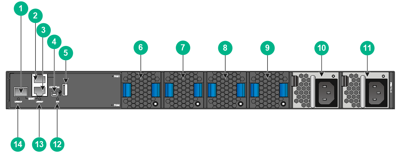
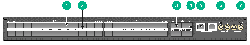
S6890-54HF
Figure2-1 Front panel
|
(1) SFP+ port |
(2) SFP+ port LED |
|
(3) QSFP28 port |
(4) QSFP28 port LED |
|
(1) Fiber management Ethernet port |
(2) Console port |
|
(3) Copper management Ethernet port |
(4) Mini USB console port |
|
(5) USB port |
(6) Fan tray 1 |
|
(7) Fan tray 2 |
(8) Fan tray 3 |
|
(9) Fan tray 4 |
(10) Fan tray 5 |
|
(11) Power supply 1 |
(12) Power supply 2 |
|
(13) System status LED (SYS) |
|
|
(14) Copper management Ethernet port LED (LINK/ACT) |
|
|
(15) Fiber management Ethernet port LED (LINK/ACT) |
|
The switch comes with power supply slot PWR1 empty and power supply slot PWR2 installed with a filler panel. You can install one or two power supplies for the switch as needed. In Figure2-2, two LSVM1AC650 power supplies are installed in the power supply slots.
The switch comes with the five fan tray slots empty. You must install five fan trays of the same model for the switch. In Figure2-2, five LSWM1FANSA fan trays are installed in the fan tray slots.
The switch comes with a dust plug in the fiber management Ethernet port. Before you use the port, remove the dust plug from it. In Figure2-2, the dust plug has been removed from the port.
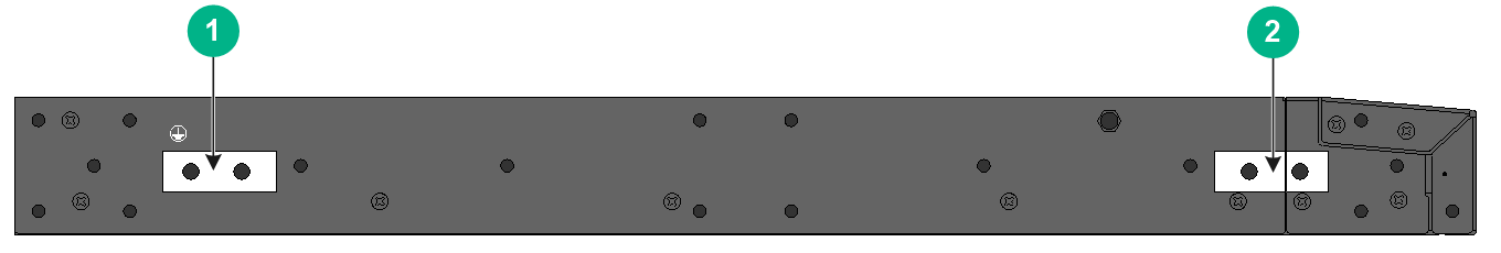
Figure2-3 Left panel
|
(1) Primary grounding point |
(2) Auxiliary grounding point |
S6890-30HF
Figure2-4 Front panel

|
(1) SFP+ port |
(2) SFP+ port LED |
|
(3) QSFP28 port |
(4) QSFP28 port LED |
|
(1) Fiber management Ethernet port |
(2) Console port |
|
(3) Copper management Ethernet port |
(4) Mini USB console port |
|
(5) USB port |
(6) Fan tray 1 |
|
(7) Fan tray 2 |
(8) Fan tray 3 |
|
(9) Fan tray 4 |
(10) Power supply 1 |
|
(11) Power supply 2 |
(12) System status LED (SYS) |
|
(13) Copper management Ethernet port LED (LINK/ACT) |
|
|
(14) Fiber management Ethernet port LED (LINK/ACT) |
|
The switch comes with power supply slot PWR1 empty and power supply slot PWR2 installed with a filler panel. You can install one or two power supplies for the switch as needed. In Figure2-5, two LSVM1AC300 power supplies are installed in the power supply slots.
The switch comes with the four fan tray slots empty. You must install four fan trays of the same model for the switch. In Figure2-5, four LSWM1FANSA fan trays are installed in the fan tray slots.
The switch comes with a dust plug in the fiber management Ethernet port. Before you use the port, remove the dust plug from it. In Figure2-5, the dust plug has been removed from the port.
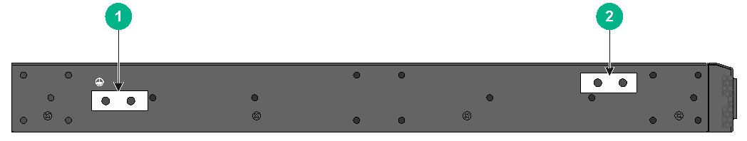
Figure2-6 Left panel
|
(1) Primary grounding point |
(2) Auxiliary grounding point |
S6890-44HF
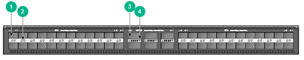
Figure2-7 Front panel
|
(1) SFP+ port |
(2) SFP+ port LED |
|
(3) QSFP28 port |
(4) QSFP28 port LED |
|
(5) 1PPS/ToD time synchronization port |
(6) SMB clock output port |
|
(7) SMB clock input port |
|
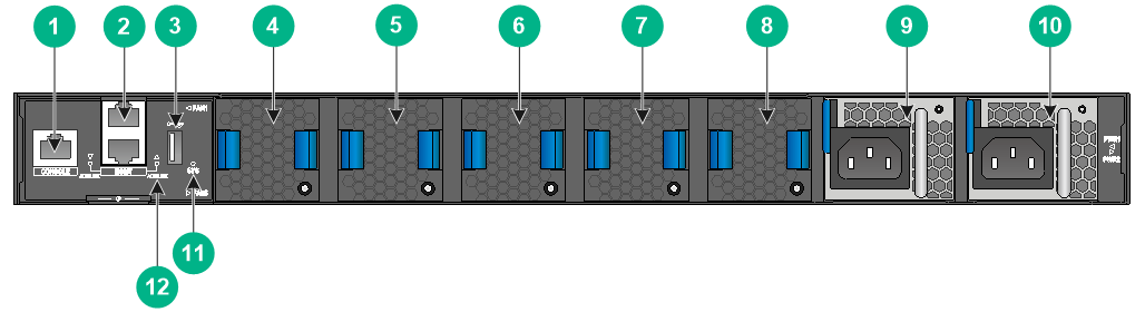
|
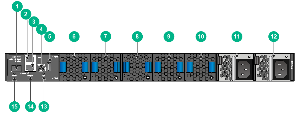
(1) Console port |
(2) Copper management Ethernet port |
|
(3) USB port |
(4) Fan tray 1 |
|
(5) Fan tray 2 |
(6) Fan tray 3 |
|
(7) Fan tray 4 |
(8) Fan tray 5 |
|
(9) Power supply 1 |
(10) Power supply 2 |
|
(11) System status LED (SYS) |
(12) Copper management Ethernet port LED (LINK/ACT) |
The switch comes with power supply slot PWR1 empty and power supply slot PWR2 installed with a filler panel. You can install one or two power supplies for the switch as needed. In Figure2-8, two PSR450-12A power supplies are installed in the power supply slots.
The switch comes with the five fan tray slots empty. You must install five fan trays of the same model for the switch. In Figure2-8, five LSPM1FANSA fan trays are installed in the fan tray slots.
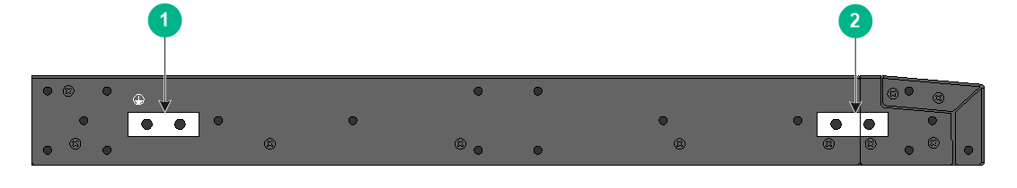
Figure2-9 Left panel
|
(1) Primary grounding point |
(2) Auxiliary grounding point |
3 FRUs
The switch uses modular design. Table3-1 describes the FRUs available for the switch.
Table3-1 FRUs available for the switch
|
FRUs |
S6890-54HF |
S6890-30HF |
S6890-44HF |
|
Power supplies |
|||
|
LSVM1AC650 |
Yes |
Yes |
No |
|
LSVM1DC650 |
Yes |
Yes |
No |
|
LSVM1AC300 |
No |
Yes |
No |
|
LSVM1DC300 |
No |
Yes |
No |
|
PSR450-12A1 |
No |
No |
Yes |
|
PSR450-12A |
No |
No |
Yes |
|
PSR450-12D |
No |
No |
Yes |
|
PSR450-12AHD |
No |
No |
Yes |
|
Fan trays |
|||
|
LSWM1FANSA |
Yes |
Yes |
No |
|
LSWM1FANSAB |
Yes |
Yes |
No |
|
LSPM1FANSB |
No |
No |
Yes |
|
LSPM1FANSA |
No |
No |
Yes |
The switch can operate correctly with only one power supply. You can install two power supplies on the switch for 1+1 redundancy.
To ensure heat dissipation, make sure all fan tray slots on the switch have fan trays installed and the fan trays are the same model.
Power supplies
|
|
WARNING! When the switch has power supplies in redundancy, you can replace a power supply without powering off the switch. Make sure the power supply to be replaced is powered off before you replace it. |
Table3-2 Power supply specifications
|
Power supply model |
Specification |
Remarks |
|
LSVM1AC650 |
· Rated input voltage: 100 VAC to 240 VAC @ 50 Hz or 60 Hz · Max input voltage: 90 VAC to 264 VAC @ 47 Hz to 63 Hz · Max output power: 650 W · Fuse melting current: 10 A @ 250 V |
For more information about the power supplies, see H3C LSVM1AC650 & LSVM1DC650 Power supplies User Manual. |
|
LSVM1DC650 |
· Rated input voltage: –40 VDC to –60 VDC · Max input voltage: –40 VDC to –72 VDC · Max output power: 650 W · Fuse melting current: 30 A @ 250 V |
|
|
LSVM1AC300 |
· Rated input voltage: 100 VAC to 240 VAC @ 50 Hz or 60 Hz · Max input voltage: 90 VAC to 264 VAC @ 47 Hz to 63 Hz · Max output power: 315 W · Fuse melting current: 6.3 A @ 250 V |
For more information about the power supplies, see H3C LSVM1AC300 & LSVM1DC300 Power supplies User Manual. |
|
LSVM1DC300 |
· Rated input voltage: –48 VDC to –60 VDC · Max input voltage: –36 VDC to –72 VDC · Max output power: 315 W · Fuse melting current: 25 A @ 250 V |
|
|
· PSR450-12A (airflow from the power supply side to the port side) · PSR450-12A1 (airflow from the port side to the power supply side) |
· Rated input voltage: 100 VAC to 240 VAC @ 50 Hz or 60 Hz · Max AC input voltage: 90 VAC to 290 VAC @ 47 Hz to 63 Hz · Rated high voltage DC input voltage: 240 VDC · Max high voltage DC input voltage: 180 VDC to 320 VDC · Max output power: 450 W · Fuse melting current: ¡ 10 A @ 250 VAC ¡ 10 A @ 310 VDC |
For more information about the power supplies, see H3C PSR450 Power supply Series User Manual. |
|
PSR450-12AHD (airflow from the port side to the power supply side) |
· Rated input voltage: 100 VAC to 240 VAC @ 50 Hz or 60 Hz · Max AC input voltage: 90 VAC to 290 VAC @ 47 Hz to 63 Hz · Rated high voltage DC input voltage: 240 VDC to 380 VDC · Max high voltage DC input voltage: 180 VDC to 400 VDC · Max output power: 450 W · Fuse melting current: 10 A @ 420 V |
|
|
PSR450-12D (airflow from the port side to the power supply side) |
· Rated input voltage: 48 VDC to 60 VDC · Max input voltage: 36 VDC to 72 VDC · Max output power: 450 W · Fuse melting current: 20 A @ 125 V |
Fan trays
Table3-3 Fan tray specifications
|
Fan tray model |
Item |
Specifications |
|
· LSWM1FANSA (airflow from the power supply side to the port side) · LSWM1FANSAB (from the port side to the power supply side) |
Dimensions |
40.6 × 42.5 × 118.7 mm (1.60 × 1.67 × 4.67 in) |
|
Fan speed |
21000 R.P.M |
|
|
Max airflow |
35 CFM |
|
|
Input voltage |
12 V |
|
|
Maximum power consumption |
30 W |
|
|
Documentation reference |
H3C LSWM1FANSA & LSWM1FANSAB Fan Trays User Guide |
|
|
· LSPM1FANSA (airflow from the power supply side to the port side) · LSPM1FANSB (airflow from the port side to the power supply side) |
Dimensions |
40 × 40 × 28 mm (1.57 × 1.57 × 1.10 in) |
|
Fan speed |
20000 R.P.M |
|
|
Max airflow |
20 CFM |
|
|
Input voltage |
12 V |
|
|
Maximum power consumption |
9.8 W |
|
|
Documentation reference |
H3C LSPM1FANSA & LSPM1FANSB Fan Trays User Guide |
4 Ports and LEDs
Ports
Console port
|
|
IMPORTANT: Do not use the serial console port and the mini USB console port at the same time. If both console ports are connected, only the serial console port is available. |
Table4-1 Serial console port specifications
|
Item |
Specification |
|
Connector type |
RJ-45 |
|
Compliant standard |
EIA/TIA-232 |
|
Transmission baud rate |
9600 bps (default) to 115200 bps |
|
Services |
· Provides connection to an ASCII terminal. · Provides connection to the serial port of a local or remote (through a pair of modems) PC running a terminal emulation program. |
Table4-2 Mini USB console port specifications
|
Item |
Specification |
|
Connector type |
USB mini-Type B |
|
Compliant standard |
USB 2.0 |
|
Transmission baud rate |
9600 bps (default) to 115200 bps |
|
Services |
· Provides connection to an ASCII terminal. · Provides connection to the USB port of a local PC running a terminal emulation program. |
Management Ethernet port
The switch has two management Ethernet ports. You can connect the ports to a local PC for software loading and debugging or to a remote management station for remote management.
Table4-3 Copper management Ethernet port specifications
|
Item |
Specification |
|
Connector type |
RJ-45 |
|
Connector number |
1 |
|
Transmission rate and working mode |
10/100/1000 Mbps, half/full duplex |
|
Transmission medium and max transmission distance |
100 m (328.08 ft) over category-5 twisted pair cable |
|
Functions and services |
Software and BootWare upgrade and network management. |
Table4-4 Fiber management Ethernet port specifications
|
Item |
Specification |
|
Connector type |
LC |
|
Connector number |
1 |
|
Transmission rate and working mode |
1000/100 Mbps, full duplex |
|
Transmission medium and max transmission distance |
See FE SFP transceiver modules in Table4-5 and GE SFP transceiver modules in Table4-8. |
|
Functions and services |
Software upgrade and network management. |
Table4-5 FE SFP transceiver modules
|
FE SFP transceiver module |
Central wavelength (nm) |
Connector |
Fiber type and diameter (µm) |
Max transmission distance |
|
SFP-FE-SX-MM1310-A |
1310 |
LC |
Multi-mode, 50/125 |
2 km (1.24 miles) |
|
Multi-mode, 62.5/125 |
||||
|
SFP-FE-LX-SM1310-A |
1310 |
LC |
Single-mode, 9/125 |
15 km (9.32 miles) |
|
SFP-FE-LH40-SM1310 |
1310 |
LC |
Single-mode, 9/125 |
40 km (24.86 miles) |
|
|
NOTE: Use the copper management Ethernet port for upgrading through BootWare. The fiber management Ethernet port cannot be used for file transmitting when the BootWare menu is used. |
USB port
The switch has one OHCI-compliant USB 2.0 port that can upload and download data at a rate up to 480 Mbps. You can use this USB port to access the file system on the flash of the switch, for example, to upload or download application and configuration files.
The USB port supplies power as per USB 2.0 specifications. Use only USB 2.0-compliant USB devices for the USB port. The port might be unable to identity USB devices that are not compliant with USB 2.0.
|
|
NOTE: USB devices from different vendors vary in compatibilities and drivers. H3C does not guarantee correct operation of USB devices from other vendors on the switch. If a USB device fails to operate on the switch, replace it with one from another vendor. |
SFP+ port
The S6890-54HF, S6890-30HF, S6890-44HF switches provide 48, 24, and 40 SFP+ ports, respectively. The SFP+ ports support the following transceiver modules and cables:
· 10-GE SFP+ transceiver modules in Table4-6.
· 10-GE SFP+ copper cables in Table4-7.
· GE SFP transceiver modules in Table4-8.
Table4-6 10-GE SFP+ transceiver modules available for the SFP+ ports
|
10-GE SFP+ transceiver module |
Central wavelength (nm) |
Connector |
Fiber type and diameter (µm) |
Modal bandwidth (MHz × km) |
Max transmission distance |
|
SFP-XG-SX-MM850-A |
850 |
LC |
Multi-mode, 50/125 |
2000 |
300 m (984.25 ft) |
|
500 |
82 m (269.03 ft) |
||||
|
400 |
66 m (216.54 ft) |
||||
|
Multi-mode, 62.5/125 |
200 |
33 m (108.27 ft) |
|||
|
160 |
26 m (85.30 ft) |
||||
|
SFP-XG-LX-SM1310 |
1310 |
LC |
Single-mode, 9/125 |
N/A |
10 km (6.21 miles) |
|
SFP-FC-8G-SW-MM850 |
850 |
LC |
Multi-mode, 62.5/125 |
200 |
150 m (492.126 ft) |
|
Multi-mode, 50/125 |
500 |
380 m (1246.72 ft) |
|||
|
2000 |
500 m (1640.42 ft) |
||||
|
SFP-FC-8G-LW-SM1310 |
1310 |
LC |
Single-mode, 9/125 |
N/A |
10 km (6.21 miles) |
Table4-7 10-GE SFP+ copper cable available for the SFP+ ports
|
10-GE SFP+ copper cable |
Max transmission distance |
|
LSWM1STK |
0.65 m (2.13 ft) |
|
LSWM2STK |
1.2 m (3.94 ft) |
|
LSWM3STK |
3 m (9.84 ft) |
|
LSTM1STK |
5 m (16.40 ft) |
|
SFP-XG-D-AOC-7M |
7 m (22.97 ft) |
|
SFP-XG-D-AOC-10M |
10 m (32.81 ft) |
|
SFP-XG-D-AOC-20M |
20 m (65.62 ft) |
Figure4-1 SFP+ copper cable
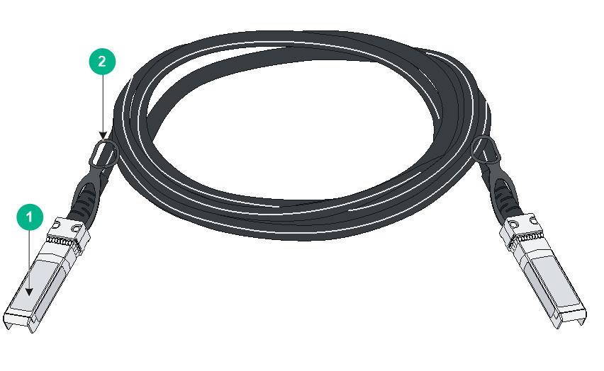
|
(1) Connector |
(2) Pull latch |
Table4-8 GE SFP transceiver modules available for the SFP+ ports
|
GE SFP transceiver module |
Central wavelength (nm) |
Connector |
Cable/Fiber type and diameter (µm) |
Modal bandwidth (MHz × km) |
Max transmission distance |
|
SFP-GE-T |
N/A |
RJ-45 |
Twisted pair cable |
N/A |
100 m (328.08 ft) |
|
SFP-GE-SX-MM850-A |
850 |
LC |
Multi-mode, 50/125 |
500 |
550 m (1804.46 ft) |
|
400 |
500 m (1640.42 ft) |
||||
|
Multi-mode, 62.5/125 |
200 |
275 m (902.23 ft) |
|||
|
160 |
220 m (721.78 ft) |
||||
|
SFP-GE-LX-SM1310-A |
1310 |
LC |
Single-mode, 9/125 |
N/A |
10 km (6.21 miles) |
|
Multi-mode, 50/125 |
500 or 400 |
550 m (1804.46 ft) |
|||
|
Multi-mode, 62.5/125 |
500 |
550 m (1804.46 ft) |
|||
|
SFP-GE-LH40-SM1310 |
1310 |
LC |
Single-mode, 9/125 |
N/A |
40 km (24.86 miles) |
|
SFP-GE-LH40-SM1550 |
1550 |
LC |
Single-mode, 9/125 |
N/A |
40 km (24.86 miles) |
|
SFP-GE-LH80-SM1550 |
1550 |
LC |
Single-mode, 9/125 |
N/A |
80 km (49.71 miles) |
|
|
NOTE: · As a best practice, use H3C transceiver modules and cables for the SFP+ ports on the switch. H3C transceiver modules and cables available for the SFP+ ports are subject to change over time. For the most up-to-date list of H3C transceiver modules and cables available for the SFP+ ports, contact H3C Support or marketing staff. · For more information about H3C transceiver modules and cables, see H3C Transceiver Modules User Guide. |
QSFP28 port
The S6890-54HF and S6890-30HF switches each provide six QSFP28 ports on the front panel. The S6890-44HF switch provides four QSFP28 ports on the front panel. You can install the following transceiver modules and cables in the QSFP28 ports:
· QSFP28 transceiver modules in Table4-9.
· QSFP28 copper cables in Table4-10.
· QSFP28 fiber cables in Table4-11.
· QSFP+ transceiver modules in Table4-12.
· QSFP+ copper cables in Table4-13.
· QSFP+ fiber cables in Table4-14.
· QSFP+ to SFP+ copper cables Table4-15.
Table4-9 QSFP28 transceiver modules available for the QSFP28 ports
|
QSFP28 transceiver module |
Central wavelength |
Connector |
Fiber type and diameter (µm) |
Modal bandwidth (MHz*km) |
Maximum transmission distance |
|
QSFP-100G-SR4-MM850 |
850 nm |
MPO (PC polished, 12-fiber) |
Multi-mode, 50/125 |
2000 |
70 m (229.66 ft) |
|
4700 |
100 m (328.08 ft) |
Table4-10 QSFP28 copper cables available for the QSFP28 ports
|
QSFP28 copper cable |
Cable length |
|
QSFP-100G-D-CAB-1M |
1 m (3.28 ft) |
|
QSFP-100G-D-CAB-3M |
|
|
QSFP-100G-D-CAB-5M |
5 m (16.40 ft) |
Table4-11 QSFP28 fiber cables available for the QSFP28 ports
|
QSFP28 fiber cable |
Cable length |
|
QSFP-100G-D-AOC-7M |
7 m (22.97 ft) |
|
QSFP-100G-D-AOC-10M |
10 m (32.81 ft) |
|
QSFP-100G-D-AOC-20M |
20 m (65.62 ft) |
Table4-12 QSFP+ transceiver modules available for the QSFP28 ports
|
Central wavelength (nm) |
Connector |
Fiber type and diameter (µm) |
Modal bandwidth (MHz × km) |
Max transmission distance |
|
|
QSFP-40G-SR4-MM850 |
850 |
MPO (PC-polished, 12-core) |
Multi-mode, 50/125 |
2000 |
100 m (328.08 ft) |
|
4700 |
150 m (492.12 ft) |
||||
|
QSFP-40G-CSR4-MM850 |
850 |
MPO (PC-polished, 12-core) |
Multi-mode, 50/125 |
2000 |
300 m (984.25 ft) |
|
4700 |
400 m (1312.33 ft) |
||||
|
QSFP-40G-LR4-WDM1300 |
Four lanes: · 1271. · 1291. · 1311. · 1331. |
LC |
Single-mode, 9/125 |
N/A |
10 km (6.21 miles) |
Table4-13 QSFP+ copper cables available for the QSFP28 ports
|
QSFP+ copper cable |
Max transmission distance |
|
LSWM1QSTK0 |
1 m (3.28 ft) |
|
LSWM1QSTK1 |
3 m (9.84 ft) |
|
LSWM1QSTK2 |
5 m (16.40 ft) |
Table4-14 QSFP+ fiber cables available for the QSFP28 ports
|
QSFP+ fiber cable |
Max transmission distance |
|
QSFP-40G-D-AOC-7M |
7 m (22.97 ft) |
|
QSFP-40G-D-AOC-10M |
10 m (32.81 ft) |
|
QSFP-40G-D-AOC-20M |
20 m (65.62 ft) |
Table4-15 QSFP+ to SFP+ copper cables available for the QSFP28 ports
|
QSFP28 to SFP28 copper cable |
Cable length |
|
LSWM1QSTK3 |
1 m (3.28 ft) |
|
LSWM1QSTK4 |
3 m (9.84 ft) |
|
LSWM1QSTK5 |
5 m (16.40 ft) |
Figure4-2 40G QSFP+/100G QSFP28 copper cable
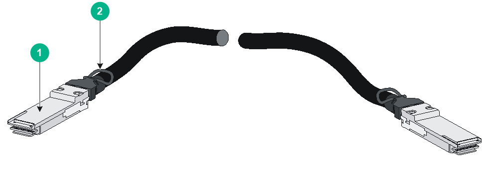
|
(1) Connector |
(2) Pull latch |
|
|
NOTE: · As a best practice, use H3C transceiver modules and cables for the QSFP28 ports on the switch. H3C transceiver modules and cables available for the QSFP28 ports are subject to change over time. For the most up-to-date list of H3C transceiver modules and cables available for the QSFP28 ports, contact H3C Support or marketing staff. · For more information about H3C transceiver modules and cables, see H3C Transceiver Modules User Guide. |
Clock port
Table4-16 SMB clock input/output port specifications
|
Item |
Specification |
|
Connector type |
SMB coaxial |
|
Port standard |
GJB681 |
|
Service |
Provides output clocking and receives input clocking at 2.048 MHz and receives and transmits signals at 2.048 Mbps. Used for time synchronization between devices and between the device and terminals. |
Table4-17 1PPS/ToD time synchronization port specifications
|
Item |
Specification |
|
Connector type |
RJ-45 |
|
Port standard |
QB-B-016-2010 |
|
Service |
You can configure the port as a time synchronization input or output port. Used for time synchronization between devices and between the device and GPS receivers or terminals. |
LEDs
System status LED
The system status LED shows the operating status of the switch.
Table4-18 System status LED description
|
LED mark |
Status |
Description |
|
SYS |
Steady green |
The switch is operating correctly. |
|
Flashing green |
The switch is performing power-on self test (POST). |
|
|
Steady red |
The system has failed POST, or a problem has occurred. |
|
|
Flashing red |
Some ports have failed POST or failed to operate. |
|
|
Off |
The switch is powered off or has failed to start up. |
QSFP28 port LED
Table4-19 QSFP28 port LED description
|
LED status |
Description |
|
Steady green |
A transceiver module or cable has been correctly installed. The port has a link and is operating at 100 Gbps. |
|
Flashing green |
The port is sending or receiving data at 100 Gbps. |
|
Steady yellow |
A transceiver module or cable has been correctly installed. The port has a link and is operating at 40 Gbps. |
|
Flashing yellow (3 Hz) |
The port is sending or receiving data at 40 Gbps. |
|
Off |
No transceiver module or cable has been installed or no link is present on the port. |
SFP+ port LED
Table4-20 SFP+ port LED description
|
LED status |
Description |
|
Steady green |
A transceiver module or cable has been correctly installed. The port has a link and is operating at 10 Gbps. |
|
Flashing green |
The port is sending or receiving data at 10 Gbps. |
|
Steady yellow |
A transceiver module or cable has been correctly installed. The port has a link and is operating at 1 Gbps. |
|
Flashing yellow (3 Hz) |
The port is sending or receiving data at 1 Gbps. |
|
Off |
No transceiver module or cable has been installed, or no link is present on the port. |
Management Ethernet port LED
Each management Ethernet port is provided with a LINK/ACT LED.
Table4-21 Copper management Ethernet port LED description
|
LED mark |
Status |
Description |
|
LINK/ACL |
Steady green |
The port is operating at 10/100/1000 Mbps and a link is present on the port |
|
Flashing green |
The port is receiving or sending data. |
|
|
Off |
No link is present on the port. |
Table4-22 Fiber management Ethernet port LED description
|
LED mark |
Status |
Description |
|
LINK/ACT |
Off |
No link is present on the port. |
|
Steady green |
The port is operating at 1000 Mbps. |
|
|
Flashing green |
The port is receiving or sending data at 1000 Mbps. |
|
|
Steady yellow |
The port is operating at 100 Mbps. |
|
|
Flashing yellow |
The port is receiving or sending data at 100 Mbps. |
Fan tray alarm LED
Each fan tray has an alarm LED.
Table4-23 Description for the alarm LED on the fan trays
|
Status |
Description |
|
On |
The fan tray is faulty. |
|
Off |
The fan tray is operating correctly or no power is being input. |
5 Cooling system
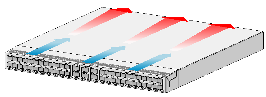
To dissipate heat timely and ensure system stability, the switch uses the front-rear air aisle cooling system. Consider the site ventilation design when you plan the installation site for the switch.
Table5-1 Cooling system for the switch
|
Switch model |
Available fan trays |
Airflow direction |
|
S6890-54HF S6890-30HF |
LSWM1FANSA |
From the power supply side to the port side |
|
LSWM1FANSAB |
From the port side to the power supply side |
|
|
S6890-44HF |
LSPM1FANSA |
From the power supply side to the port side |
|
LSPM1FANSB |
From the port side to the power supply side |
Figure5-1 Airflow from the power supply side to the port side (LSWM1FANSA)(S6890-54HF)
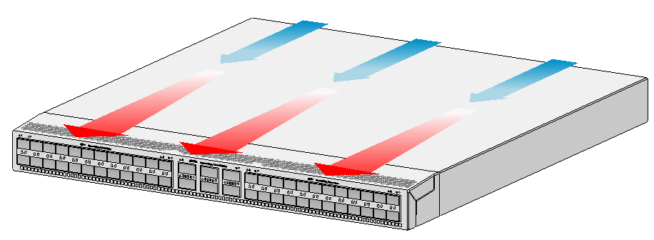
Figure5-2 Airflow from the port side to the power supply side (LSWM1FANSAB)(S6890-54HF)
6 Chassis ordering information
To purchase an S6890 chassis, contact the sales agent or H3C sales personnel.
Table6-1 S6890 chassis ordering information
|
Product code |
Product name |
Description |
|
0235A2AB |
S6890-54HF |
H3C S6890-54HF L3 Ethernet switch |
|
0235A3L5 |
S6890-30HF |
H3C S6890-30HF L3 Ethernet switch |
|
0235A2H8 |
S6890-44HF |
H3C S6890-44HF L3 Ethernet switch |