- Table of Contents
- Related Documents
-
| Title | Size | Download |
|---|---|---|
| 02-EVPN VXLAN configuration | 658.49 KB |
Contents
Assignment of traffic to VXLANs
Traffic from the local site to a remote site
Traffic from a remote site to the local site
Centralized EVPN gateway deployment
Distributed EVPN gateway deployment
About distributed EVPN gateway deployment
Restrictions and guidelines: EVPN VXLAN configuration
Configuring BGP to advertise BGP EVPN routes
Restrictions and guidelines for BGP EVPN route advertisement
Enabling BGP to advertise BGP EVPN routes
Configuring route advertisement settings
Preferring routes with an IPv6 next hop during optimal route selection
Mapping a Layer 3 interface to a VSI
Configuring a centralized EVPN gateway
Configuring a distributed EVPN gateway
Restrictions and guidelines for distributed EVPN gateway configuration
Prerequisites for distributed EVPN gateway configuration
Configuring the traffic forwarding mode for EVPN VXLAN
Configuring an L3 VXLAN ID for a VSI interface
Configuring IP prefix route advertisement
Configuring BGP route exchange between the public instance and VPN instances
Managing remote MAC address entries and remote ARP learning
Disabling remote MAC address learning and remote ARP learning
Disabling MAC address advertisement
Enabling MAC mobility event suppression
Disabling learning of MAC addresses from ARP information
Enabling ARP mobility event suppression
Configuring BGP EVPN route redistribution and advertisement
Redistributing MAC/IP advertisement routes into BGP unicast routing tables
Enabling BGP EVPN route advertisement to the local site
Enabling ARP or ND flood suppression
Verifying and maintaining EVPN VXLAN
Displaying EVPN running status and statistics
Verifying MAC address information and ARP and ND information
EVPN VXLAN configuration examples
Example: Configuring a centralized IPv4 EVPN gateway
Example: Configuring distributed IPv4 EVPN gateways in symmetric IRB mode
Example: Configuring distributed IPv6 EVPN gateways in symmetric IRB mode
Example: Configuring distributed IPv4 EVPN gateways in asymmetric IRB mode
Example: Configuring IPv4 EVPN VXLAN multihoming
EVPN VXLAN overview
EVPN VXLAN uses EVPN routes for VXLAN tunnel establishment and assignment and MAC reachability information advertisement in the control plane and uses VXLAN for forwarding in the data plane.
EVPN network model
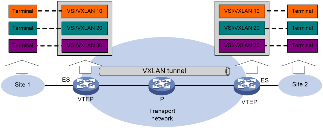
As shown in Figure 1, EVPN uses the VXLAN technology for traffic forwarding in the data plane. The transport edge devices assign user terminals to different VXLANs, and then forward traffic between sites for user terminals by using VXLAN tunnels. The transport edge devices are VXLAN tunnel endpoints (VTEPs). They can be servers that host VMs or independent network devices.
Supported user terminals include PCs, wireless terminals, and VMs on servers.
|
|
NOTE: This document uses VMs as examples to describe the mechanisms of EVPN. The mechanisms do not differ between different kinds of user terminals. |
A VTEP uses ESs, VSIs, and VXLAN tunnels to provide VXLAN services:
· Ethernet segment (ES)—An ES is a link that connects a site to a VTEP. Each ES is uniquely identified by an Ethernet segment identifier (ESI).
· VSI—A virtual switch instance is a virtual Layer 2 switched domain. Each VSI provides switching services only for one VXLAN. VSIs learn MAC addresses and forward frames independently of one another. User terminals in different sites have Layer 2 connectivity if they are in the same VXLAN. A VXLAN is identified by a 24-bit VXLAN ID which is also called the virtual network identifier (VNI). A VXLAN corresponds to an EVPN instance.
· VXLAN tunnel—Logical point-to-point tunnels between VTEPs over the transport network. Each VXLAN tunnel can trunk multiple VXLANs.
All VXLAN processing is performed on VTEPs. The ingress VTEP encapsulates VXLAN traffic in the VXLAN, outer UDP, and outer IP headers, and forwards the traffic through VXLAN tunnels. The egress VTEP removes the VXLAN encapsulation and forwards the traffic to the destination. Transport network devices (for example, the P device in Figure 1) forward VXLAN traffic only based on the outer IP header of VXLAN packets.
Configuration automation
If EVPN is used for Layer 2 forwarding, VTEPs use the following BGP EVPN routes to discover VTEP neighbors, establish VXLAN tunnels, and assign the tunnels to VXLANs:
· IMET route—VTEPs advertise their VXLAN IDs through IMET routes. If two VTEPs have the same VXLAN ID, they automatically establish a VXLAN tunnel and assign the tunnel to the VXLAN.
· MAC/IP advertisement route—VTEPs advertise local MAC addresses and VXLAN IDs through MAC/IP advertisement routes. If two VTEPs have the same VXLAN ID, they automatically establish a VXLAN tunnel and assign the tunnel to the VXLAN.
If EVPN is used for Layer 3 forwarding, VTEPs use the following BGP EVPN routes to discover VTEP neighbors, establish VXLAN tunnels, and assign the tunnels to VXLANs:
· IMET route—VTEPs advertise the VXLAN IDs they have through IMET routes. If two VTEPs have the same VXLAN ID, they automatically establish a VXLAN tunnel and assign the tunnel to the VXLAN.
· MAC/IP advertisement route and IP prefix advertisement route—In the EVPN gateway deployment, VTEPs advertise MAC/IP advertisement routes or IP prefix advertisement routes which carry the export targets. When a VTEP receives a route, it compares the export targets of the route with the local import targets. If the route targets match, the VTEP establishes a VXLAN tunnel with the remote VTEP and associates the tunnel with the L3 VXLAN ID of the corresponding VPN instance. For more information about the L3 VXLAN ID, see "Distributed EVPN gateway deployment."
Assignment of traffic to VXLANs
Traffic from the local site to a remote site
The VTEP uses a Layer 3 interface to match customer traffic. The VTEP assigns customer traffic to a VXLAN by mapping the Layer 3 interface to a VSI.
A Layer 3 interface is identical to an attachment circuit (AC) in L2VPN.
Traffic from a remote site to the local site
When a VXLAN packet arrives at a VXLAN tunnel interface, the VTEP uses the VXLAN ID in the packet to identify its VXLAN.
Layer 2 forwarding
MAC learning
The VTEP performs Layer 2 forwarding based on a VSI's MAC address table. The VTEP learns MAC addresses by using the following methods:
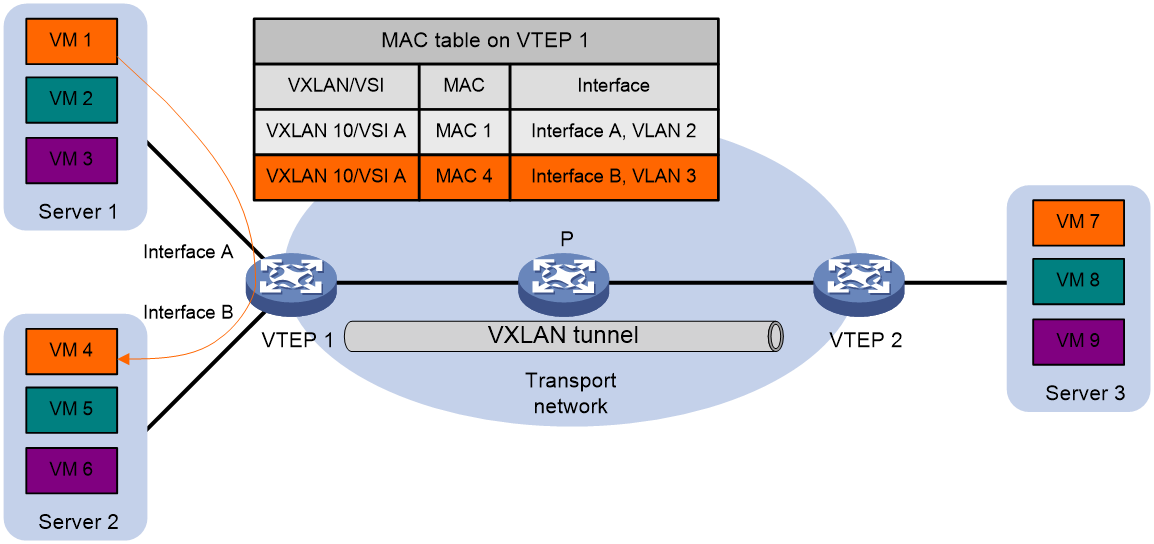
· Local MAC learning—The VTEP automatically learns the source MAC addresses of frames sent from the local site. The outgoing interfaces of local MAC address entries are site-facing interfaces on which the MAC addresses are learned.
· Remote MAC learning—The VTEP uses MP-BGP to advertise local MAC reachability information to remote sites and learn MAC reachability information from remote sites. The outgoing interfaces of MAC address entries advertised from a remote site are VXLAN tunnel interfaces.
Unicast
As shown in Figure 2, the VTEP performs typical Layer 2 forwarding for known unicast traffic within the local site.
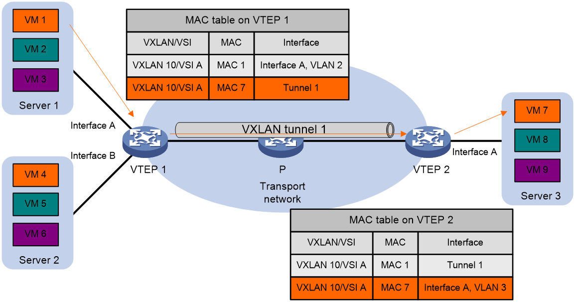
As shown in Figure 3, the following process applies to a known unicast frame between sites:
1. The source VTEP encapsulates the Ethernet frame in the VXLAN/UDP/IP header.
In the outer IP header, the source IP address is the source VTEP's VXLAN tunnel source IP address. The destination IP address is the VXLAN tunnel destination IP address.
2. The source VTEP forwards the encapsulated packet out of the outgoing VXLAN tunnel interface found in the VSI's MAC address table.
3. The intermediate transport devices (P devices) forward the packet to the destination VTEP by using the outer IP header.
4. The destination VTEP removes the headers on top of the inner Ethernet frame. It then performs MAC address table lookup in the VXLAN's VSI to forward the frame out of the matching outgoing interface.
Flood
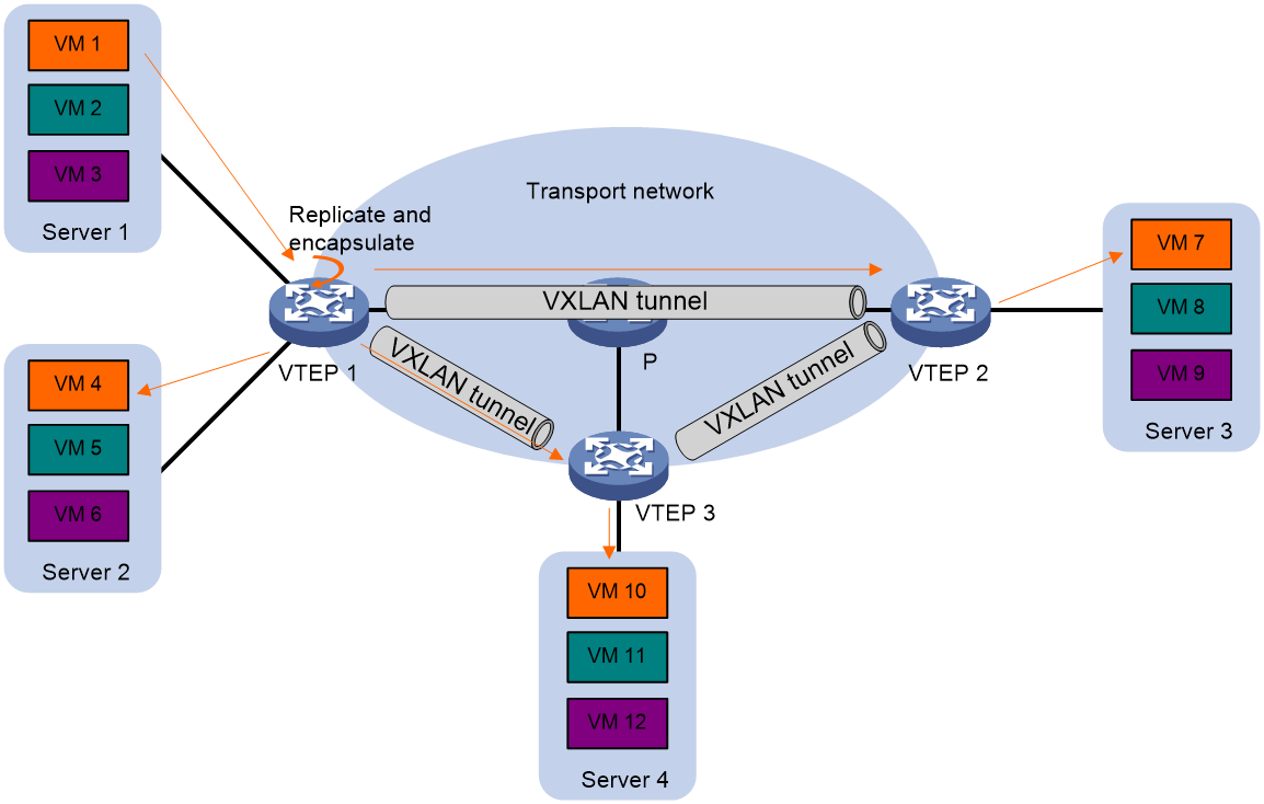
As shown in Figure 4, a VTEP floods a broadcast, multicast, or unknown unicast frame to all site-facing interfaces and VXLAN tunnels in the VXLAN, except for the incoming interface. The source VTEP replicates the flood frame, and then sends one replica to the destination IP address of each VXLAN tunnel in the VXLAN. Each destination VTEP floods the inner Ethernet frame to all the site-facing interfaces in the VXLAN. To avoid loops, the destination VTEPs do not flood the frame to VXLAN tunnels.
Figure 4 Forwarding of flood traffic
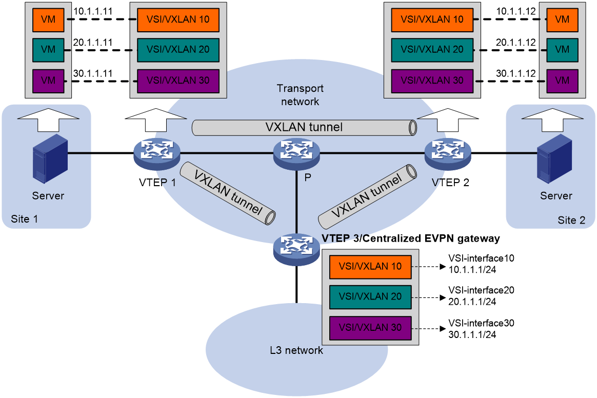
Centralized EVPN gateway deployment
Centralized EVPN gateway deployment uses one VTEP to provide Layer 3 forwarding for VXLANs. The VTEP uses virtual Layer 3 VSI interfaces as gateway interfaces for VXLANs. Typically, the gateway-collocated VTEP connects to other VTEPs and the external network. To use this design, make sure the gateway has sufficient bandwidth and processing capability. A centralized EVPN gateway can provide services only for IPv4 sites.
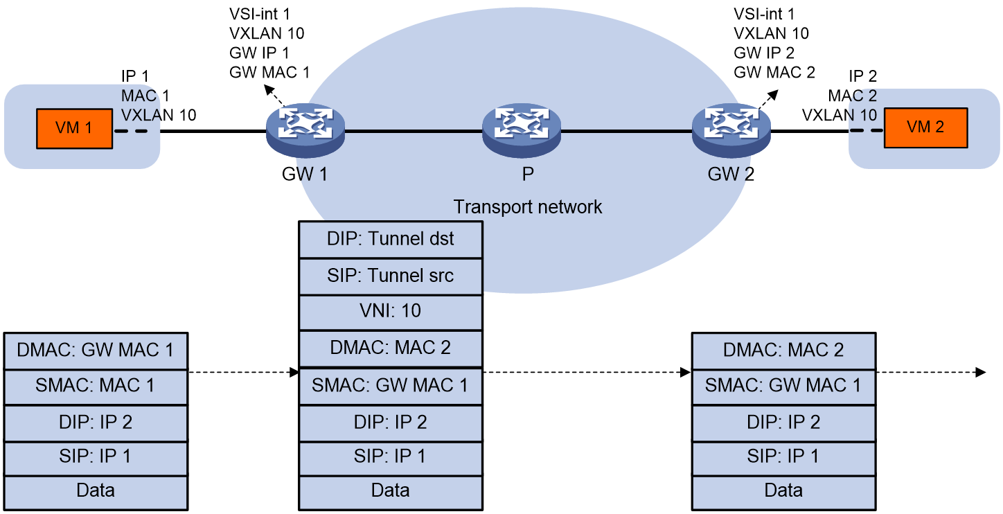
As shown in Figure 5, a VTEP acts as a gateway for VMs in the VXLANs. The VTEP both terminates the VXLANs and performs Layer 3 forwarding for the VMs. The network uses the following process to forward Layer 3 traffic from a VM to the destination:
1. The VM sends an ARP request to obtain the MAC address of the VSI interface that acts as the gateway, and then sends the Layer 3 traffic to the centralized EVPN gateway.
2. The local VTEP looks up the matching VSI's MAC address table and forwards the traffic to the centralized EVPN gateway through a VXLAN tunnel.
3. The centralized EVPN gateway removes the VXLAN encapsulation and forwards the traffic at Layer 3.
4. The centralized EVPN gateway forwards the replies sent by the destination node to the VM based on the ARP entry for the VM.
Figure 5 Example of centralized EVPN gateway deployment
Distributed EVPN gateway deployment
About distributed EVPN gateway deployment
As shown in Figure 6, each site's VTEP acts as a gateway to perform Layer 3 forwarding for the VXLANs of the local site. A VTEP acts as a border gateway to the Layer 3 network for the VXLANs.
Figure 6 Distributed EVPN gateway placement design
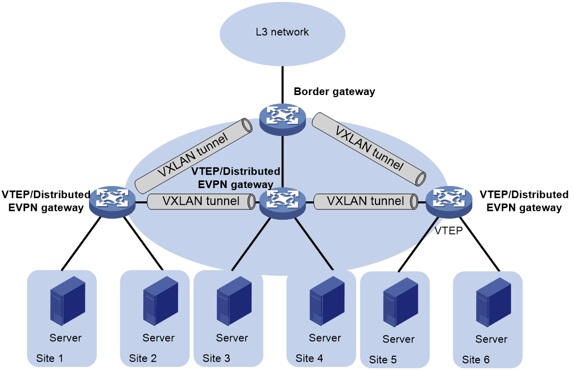
A distributed EVPN gateway supports the following traffic forwarding modes:
· Asymmetric IRB—The ingress gateway performs Layer 2 and Layer 3 lookups and the egress gateway performs only Layer 2 forwarding.
· Symmetric IRB—Both the ingress and egress gateways perform Layer 2 and Layer 3 lookups.
Symmetric IRB
Basic concepts
Symmetric IRB introduces the following concepts:
· L3 VXLAN ID—Also called L3 VNI. An L3 VXLAN ID identifies the traffic of a routing domain where devices have Layer 3 reachability. An L3 VXLAN ID is associated with one VPN instance. Distributed EVPN gateways use VPN instances to isolate traffic of different services on VXLAN tunnel interfaces.
· Router MAC address—Each distributed EVPN gateway has a unique router MAC address used for inter-gateway forwarding. The MAC addresses in the inner Ethernet header of VXLAN packets are router MAC addresses of distributed EVPN gateways.
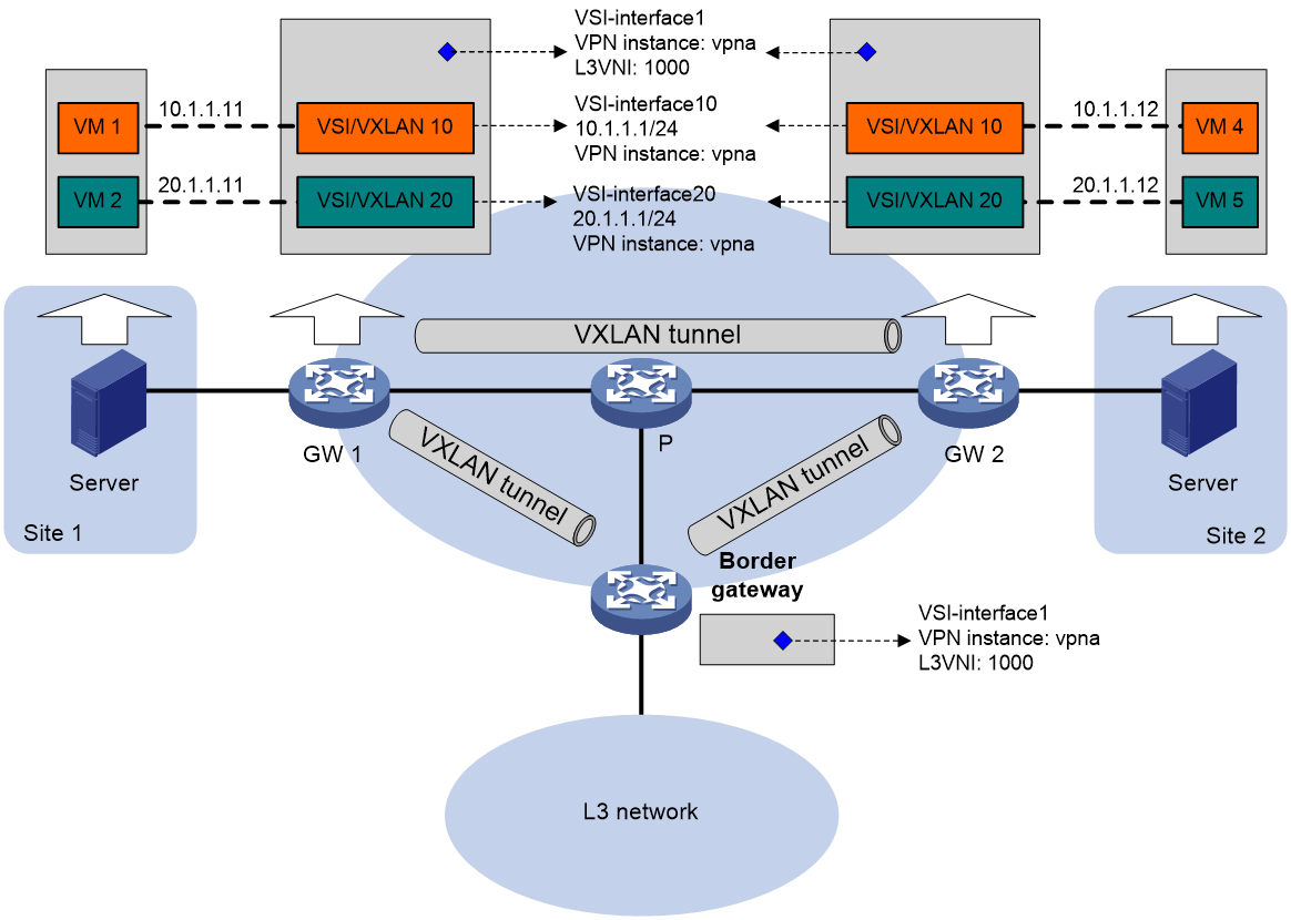
VSI interfaces
As shown in Figure 7, each distributed EVPN gateway has the following types of VSI interfaces:
· VSI interface as a gateway interface of a VXLAN—The VSI interface acts as the gateway interface for VMs in a VXLAN. The VSI interface is associated with a VSI and a VPN instance. On different distributed EVPN gateways, the VSI interface of a VXLAN use the same IP address to provide services.
· VSI interface associated with an L3 VXLAN ID—The VSI interface is associated with a VPN instance and assigned an L3 VXLAN ID. VSI interfaces associated with the same VPN instance share an L3 VXLAN ID.
A border gateway only has VSI interfaces that are associated with an L3 VXLAN ID.
Figure 7 Example of distributed EVPN gateway deployment
Layer 3 forwarding entry learning
A distributed EVPN gateway forwards Layer 3 traffic based on FIB entries generated from BGP EVPN routes and ARP information.
A VTEP advertises an external route imported in the EVPN address family through MP-BGP. A remote VTEP adds the route to the FIB table of a VPN instance based on the L3 VXLAN ID carried in the route. In the FIB entry, the outgoing interface is a VXLAN tunnel interface, and the next hop is the peer VTEP address in the NEXT_HOP attribute of the route.
A VTEP has the following types of ARP information:
· Local ARP information—ARP information of VMs in the local site. The VTEP snoops GARP packets, RARP packets, and ARP requests for the gateway MAC address to learn the ARP information of the senders and generates ARP entries and FIB entries. In an ARP or FIB entry, the outgoing interface is the site-facing interface where the packet is received, and the VPN instance is the instance associated with the corresponding VSI interface.
· Remote ARP information—ARP information of VMs in remote sites. Each VTEP uses MP-BGP to advertise its local ARP information with L3 VXLAN IDs in routes to remote sites. A VTEP generates only FIB entries for the remote ARP information. A FIB entry contains the following information:
¡ Outgoing interface: VSI interface associated with the L3 VXLAN ID.
¡ Next hop: Peer VTEP address in the NEXT_HOP attribute of the route.
¡ VPN instance: VPN instance associated with the L3 VXLAN ID.
The VTEP then creates an ARP entry for the next hop in the FIB entry.
Traffic forwarding
A distributed EVPN gateway can work in one of the following mode:
· Switching and routing mode—Forwards Layer 2 traffic based on the MAC address table and forwards Layer 3 traffic based on the FIB table. In this mode, you need to enable ARP flood suppression on the distributed EVPN gateway to reduce flooding.
· Routing mode— Forwards both Layer 2 and Layer 3 traffic based on the FIB table. In this mode, you need to enable local proxy ARP on the distributed EVPN gateway.
For more information about MAC address table-based Layer 2 forwarding, see "Unicast."
Figure 8 shows the intra-site Layer 3 forwarding process.
1. The source VM sends an ARP request to obtain the MAC address of the destination VM.
2. The gateway replies to the source VM with the MAC address of the VSI interface associated with the source VM's VSI.
3. The source VM sends a Layer 3 packet to the gateway.
4. The gateway looks up the FIB table of the VPN instance associated with the source VM's VSI and finds the matching outgoing site-facing interface.
5. The gateway processes the Ethernet header of the Layer 3 packet as follows:
¡ Replaces the destination MAC address with the destination VM's MAC address.
¡ Replaces the source MAC address with the VSI interface's MAC address.
6. The gateway forwards the Layer 3 packet to the destination VM.
Figure 8 Intra-site Layer 3 forwarding
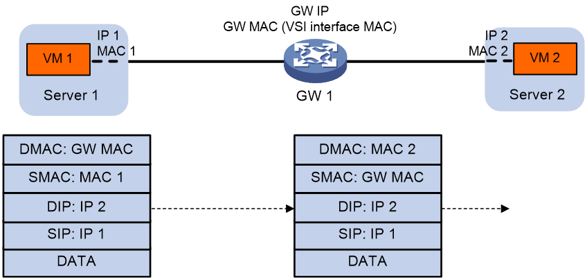
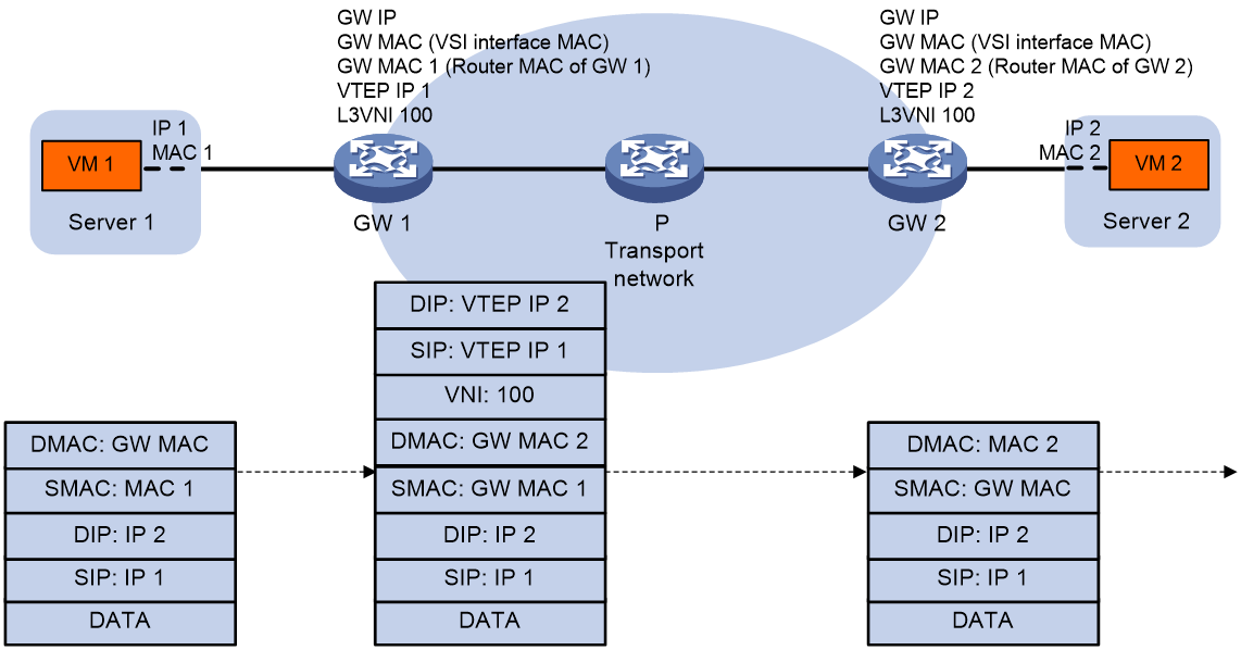
Figure 9 shows the inter-site Layer 3 forwarding process.
1. The source VM sends an ARP request to obtain the MAC address of the destination VM.
2. The gateway replies to the source VM with the MAC address of the VSI interface associated with the source VM's VSI.
3. The source VM sends a Layer 3 packet to the gateway.
4. The gateway looks up the FIB table of the VPN instance associated with the source VM's VSI and finds the matching outgoing VSI interface.
5. The gateway processes the Ethernet header of the Layer 3 packet as follows:
¡ Replaces the destination MAC address with the destination gateway's router MAC address.
¡ Replaces the source MAC address with its own router MAC address.
6. The gateway adds VXLAN encapsulation to the Layer 3 packet and forwards the packet to the destination gateway. The encapsulated VXLAN ID is the L3 VXLAN ID of the corresponding VPN instance.
7. The destination gateway identifies the VPN instance of the packet based on the L3 VXLAN ID and removes the VXLAN encapsulation. Then the gateway forwards the packet based on the matching ARP entry.
Figure 9 Inter-site Layer 3 forwarding
Communication between private and public networks
A distributed EVPN gateway uses the public instance to perform Layer 3 forwarding for the public network and to enable communication between private and public networks. The public instance is similar to a VPN instance. A distributed EVPN gateway processes traffic of the public instance in the same way it does for a VPN instance. For the public instance to work correctly, you must configure an RD, an L3 VXLAN ID, and route targets for it. If a VSI interface is not associated with any VPN instance, the VSI interface belongs to the public instance.
Asymmetric IRB
VSI interfaces
Asymmetric IRB uses the same distributed EVPN gateway deployment as symmetric IRB.
As shown in Figure 10, each distributed EVPN gateway has the following types of VSI interfaces:
· VSI interface as a gateway interface of a VXLAN—The VSI interface is associated with a VSI and a VPN instance. On different distributed EVPN gateways, the VSI interface of a VXLAN must use different IP addresses to provide services.
· VSI interface associated with an L3 VXLAN ID—The VSI interface acts as the gateway for VMs in a VXLAN to communicate with the external network through the border gateway. The VSI interface is associated with a VPN instance and assigned an L3 VXLAN ID. VSI interfaces associated with the same VPN instance share an L3 VXLAN ID.
A border gateway only has VSI interfaces that are associated with an L3 VXLAN ID.
Layer 3 forwarding
Asymmetric IRB supports only Layer 3 forwarding in the same VXLAN on distributed EVPN gateways.
After a distributed EVPN gateway learns ARP information about local VMs, it advertises the information to other distributed EVPN gateways through MAC/IP advertisement routes. Other distributed EVPN gateways generate FIB entries based on the advertised ARP information.
As shown in Figure 10, VM 1 and VM 2 belong to VXLAN 10 and they can reach each other at Layer 3 through the distributed EVPN gateways. The distributed EVPN gateways use the following process to perform Layer 3 forwarding in asymmetric IRB mode when VM 1 sends a packet to VM 2:
1. After GW 1 receives the packet from VM 1, it finds that the destination MAC address is itself. Then, GW 1 removes the Layer 2 frame header and looks up the FIB table for the destination IP address.
2. GW 1 matches the packet to the FIB entry generated based on the ARP information of VM 2.
3. GW 1 encapsulates the packet source and destination MAC addresses as the MAC addresses of GW 1 and VM 2, respectively. Then, GW 1 adds VXLAN encapsulation to the packet and forwards the packet to GW 2 through a VXLAN tunnel.
4. GW 2 removes the VXLAN encapsulation from the packet, and performs Layer 2 forwarding in VXLAN 10 by looking up the MAC address table for the destination MAC address.
5. GW 2 forwards the packet to VM 2 based on the MAC address table lookup result.
Figure 10 Layer 3 forwarding in the same VXLAN (asymmetric IRB)
ARP and ND flood suppression
ARP or ND flood suppression reduces ARP request broadcasts or ND request multicasts by enabling the VTEP to reply to ARP or ND requests on behalf of VMs.
As shown in Figure 11, this feature snoops ARP or ND requests, ARP or ND responses, and BGP EVPN routes to populate the ARP or ND flood suppression table with local and remote MAC addresses. If an ARP or ND request has a matching entry, the VTEP replies to the request on behalf of the VM. If no match is found, the VTEP floods the request to both local and remote sites.
Figure 11 ARP flood suppression
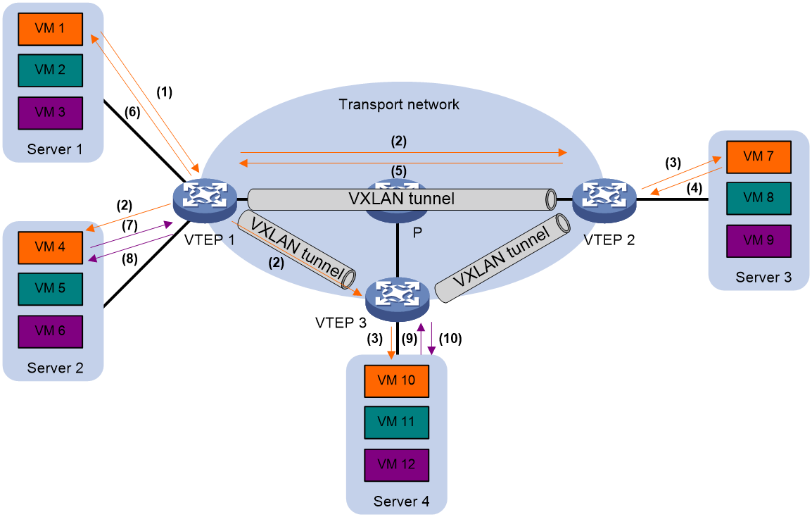
The following uses ARP flood suppression as an example to explain the flood suppression workflow:
1. VM 1 sends an ARP request to obtain the MAC address of VM 7.
2. VTEP 1 creates a suppression entry for VM 1, floods the ARP request in the VXLAN, and sends the suppression entry to VTEP 2 and VTEP 3 through BGP EVPN.
3. VTEP 2 and VTEP 3 de-encapsulate the ARP request and broadcast the request in the local site.
4. VM 7 sends an ARP reply.
5. VTEP 2 creates a suppression entry for VM 7, forwards the ARP reply to VTEP 1, and sends the suppression entry to VTEP 1 and VTEP 3 through BGP EVPN.
6. VTEP 1 de-encapsulates the ARP reply and forwards the ARP reply to VM 1.
7. VM 4 sends an ARP request to obtain the MAC address of VM 1.
8. VTEP 1 creates a suppression entry for VM 4 and replies to the ARP request.
9. VM 10 sends an ARP request to obtain the MAC address of VM 1.
10. VTEP 3 creates a suppression entry for VM 10 and replies to the ARP request.
MAC mobility
MAC mobility refers to that a VM or host moves from one ES to another. The source VTEP is unaware of the MAC move event. To notify other VTEPs of the change, the destination VTEP advertises a MAC/IP advertisement route for the MAC address. The source VTEP withdraws the old route for the MAC address after receiving the new route. The MAC/IP advertisement route has a sequence number that increases when the MAC address moves. The sequence number identifies the most recent move if the MAC address moves multiple times.
Configuring EVPN VXLAN
Restrictions and guidelines: EVPN VXLAN configuration
Make sure the following VXLAN tunnels are not associated with the same VXLAN when they have the same tunnel destination IP address:
· A VXLAN tunnel automatically created by EVPN.
· A manually created VXLAN tunnel.
For more information about manual tunnel configuration, see VXLAN Configuration Guide.
As a best practice to ensure correct traffic forwarding, configure the same MAC address for all VSI interfaces on an EVPN gateway.
EVPN VXLAN tasks at a glance
To configure EVPN VXLAN, perform the following tasks:
1. Configuring a VXLAN on a VSI
2. Configuring an EVPN instance
3. Configuring BGP to advertise BGP EVPN routes
a. Enabling BGP to advertise BGP EVPN routes
b. (Optional.) Configuring route advertisement settings
c. (Optional.) Preferring routes with an IPv6 next hop during optimal route selection
d. (Optional.) Maintaining BGP sessions
5. Configuring an EVPN gateway
Choose one of the following tasks:
¡ Configuring a centralized EVPN gateway
¡ Configuring a distributed EVPN gateway
6. (Optional.) Managing remote MAC address entries and remote ARP learning
¡ Disabling remote MAC address learning and remote ARP learning
¡ Disabling MAC address advertisement
¡ Enabling MAC mobility event suppression
¡ Disabling learning of MAC addresses from ARP information
¡ Enabling ARP mobility event suppression
7. (Optional.) Enabling BGP EVPN route advertisement to the local site
8. (Optional.) Maintaining and optimizing an EVPN network
¡ Disabling flooding for a VSI
¡ Enabling ARP or ND flood suppression
Configuring a VXLAN on a VSI
Restrictions and guidelines
For more information about the VXLAN commands in this task, see VXLAN Command Reference.
Procedure
1. Enter system view.
system-view
2. Enable L2VPN.
l2vpn enable
By default, L2VPN is disabled.
3. Create a VSI and enter VSI view.
vsi vsi-name
4. Configure a VSI description.
description text
By default, a VSI does not have a description.
5. Enable the VSI.
undo shutdown
By default, a VSI is enabled.
6. Create a VXLAN and enter VXLAN view.
vxlan vxlan-id
You can create only one VXLAN on a VSI. The VXLAN ID must be unique for each VSI.
Configuring an EVPN instance
About this task
You do not need to associate a VPN instance with a VXLAN that requires only Layer 2 connectivity. The BGP EVPN routes advertised by the device carry the RD and route targets configured for the EVPN instance associated with the VXLAN.
Procedure
1. Enter system view.
system-view
2. Enter VSI view.
vsi vsi-name
3. Create a VSI EVPN instance and enter VSI EVPN instance view.
evpn encapsulation vxlan
4. Configure an RD for the EVPN instance.
route-distinguisher { route-distinguisher | auto }
By default, no RD is configured for an EVPN instance.
5. Configure route targets for the EVPN instance.
vpn-target { vpn-target&<1-8> | auto } [ both | export-extcommunity | import-extcommunity ]
By default, an EVPN instance does not have route targets.
Make sure the following requirements are met:
¡ The import targets of the EVPN instance do not match the export targets of the VPN instance associated with the VXLAN or the public instance.
¡ The export targets of the EVPN instance do not match the import targets of the VPN instance associated with the VXLAN or the public instance.
For more information about VPN instance configuration and public instance configuration, see "Configuring an L3 VXLAN ID for a VSI interface."
6. (Optional.) Apply an export routing policy to EVPN.
export route-policy route-policy
By default, no export routing policy is applied to EVPN.
7. (Optional.) Apply an import routing policy to EVPN.
import route-policy route-policy
By default, no import routing policy is applied to EVPN. A VPN instance accepts a route when the route targets of the route match local import route targets.
Configuring BGP to advertise BGP EVPN routes
Restrictions and guidelines for BGP EVPN route advertisement
For more information about BGP commands in this task, see Layer 3—IP Routing Command Reference.
Enabling BGP to advertise BGP EVPN routes
1. Enter system view.
system-view
2. Configure a global router ID.
router id router-id
By default, no global router ID is configured.
3. Enable a BGP instance and enter BGP instance view.
bgp as-number [ instance instance-name ]
By default, BGP is disabled and no BGP instances exist.
4. Specify remote VTEPs as BGP peers.
peer { group-name | ipv4-address [ mask-length ] } as-number as-number
5. Create the BGP EVPN address family and enter BGP EVPN address family view.
address-family l2vpn evpn
6. Enable BGP to exchange BGP EVPN routes with a peer or peer group.
peer { group-name | ipv4-address [ mask-length ] } enable
By default, BGP does not exchange BGP EVPN routes with peers.
Configuring route advertisement settings
1. Enter system view.
system-view
2. Enter BGP instance view.
bgp as-number [ instance instance-name ]
3. Enter BGP EVPN address family view.
address-family l2vpn evpn
4. Permit the local AS number to appear in routes from a peer or peer group and set the number of appearances.
peer { group-name | ipv4-address [ mask-length ] } allow-as-loop [ number ]
By default, the local AS number is not allowed in routes from peers.
5. Enable route target filtering for BGP EVPN routes.
policy vpn-target
By default, route target filtering is enabled for BGP EVPN routes.
6. Configure BGP route reflection settings:
a. Configure the device as an RR and specify a peer or peer group as its client.
peer { group-name | ipv4-address [ mask-length ] } reflect-client
By default, no RR or client is configured.
b. (Optional.) Enable BGP EVPN route reflection between clients.
reflect between-clients
By default, BGP EVPN route reflection between clients is enabled.
c. (Optional.) Configure the cluster ID of the RR.
reflector cluster-id { cluster-id | ipv4-address }
By default, an RR uses its own router ID as the cluster ID.
d. (Optional.) Create a reflection policy for the RR to filter reflected BGP EVPN routes.
rr-filter { ext-comm-list-number | ext-comm-list-name }
By default, an RR does not filter reflected BGP EVPN routes.
7. Configure the device to not change the next hop of routes advertised to an EBGP peer or peer group.
peer { group-name | ipv4-address [ mask-length ] | ipv6-address [ prefix-length ] } next-hop-invariable
By default, the device uses its address as the next hop of routes advertised to EBGP peers.
8. Set a preferred value for routes received from a peer or peer group.
peer { group-name | ipv4-address [ mask-length ] | ipv6-address [ prefix-length ] } preferred-value value
By default, the preferred value is 0 for routes received from a peer or peer group.
9. Apply a routing policy to routes received from or advertised to a peer or peer group.
peer { group-name | ipv4-address [ mask-length ] } route-policy route-policy-name { export | import }
By default, no routing policies are applied to routes received from or advertised to peers or peer groups.
10. Advertise the COMMUNITY attribute to a peer or peer group.
peer { group-name | ipv4-address [ mask-length ] } advertise-community
By default, the device does not advertise the COMMUNITY attribute to peers or peer groups.
11. Configure the BGP additional path feature:
¡ Configure BGP additional path capabilities.
peer { group-name | ipv4-address [ mask-length ] } additional-paths { receive | send } *
By default, no BGP Additional Paths capabilities are configured.
¡ Set the maximum number of Add-Path optimal routes that can be advertised to a peer or peer group.
peer { group-name | ipv4-address [ mask-length ] } advertise additional-paths best number
By default, a maximum of one Add-Path optimal route can be advertised to a peer or peer group.
¡ Set the maximum number of Add-Path optimal routes that can be advertised to all peers.
additional-paths select-best best-number
By default, a maximum of one Add-Path optimal route can be advertised to all peers.
12. Enable BGP FRR.
pic
By default, BGP FRR is disabled.
Preferring routes with an IPv6 next hop during optimal route selection
About this task
Configure this feature for the VXLAN packets in an EVPN network to be forwarded through IPv6 routes when both IPv4 and IPv6 routes exist.
Procedure
1. Enter system view.
system-view
2. Enter BGP instance view.
bgp as-number [ instance instance-name ]
3. Enter BGP EVPN address family view.
address-family l2vpn evpn
4. Enable BGP to prefer routes with an IPv6 next hop during optimal route selection.
bestroute ipv6-nexthop
By default, BGP prefers routes with an IPv4 next hop during optimal route selection.
Maintaining BGP sessions
Perform the following tasks in user view:
· Reset BGP sessions of the BGP EVPN address family.
reset bgp [ instance instance-name ] { as-number | ipv4-address [ mask-length ] | all | external | group group-name | internal } l2vpn evpn
· Soft-reset BGP sessions of the BGP EVPN address family.
refresh bgp [ instance instance-name ] { ipv4-address [ mask-length ] | all | external | group group-name | internal } { export | import } l2vpn evpn
Mapping ACs to a VSI
Mapping a Layer 3 interface to a VSI
About this task
To assign the customer traffic on a Layer 3 interface to a VXLAN, map the interface to the VXLAN's VSI. The VSI uses its MAC address table to forward the customer traffic.
For more information about the VXLAN commands in this task, see VXLAN Command Reference.
Restrictions and guidelines
Link aggregation group membership is mutually exclusive with VSI mappings on a Layer 3 interface. Do not map a VSI to a Layer 3 interface that is in a Layer 3 aggregation group.
Procedure
1. Enter system view.
system-view
2. Enter Layer 3 interface view.
interface interface-type interface-number
3. Map the Layer 3 interface to a VSI.
xconnect vsi vsi-name [ track track-entry-number&<1-3> ]
By default, a Layer 3 interface is not mapped to any VSI.
Configuring a centralized EVPN gateway
Restrictions and guidelines
If an EVPN network contains a centralized EVPN gateway, you must enable ARP or ND flood suppression on VTEPs. Typically remote ARP or ND learning is disabled in an EVPN network. When ARP or ND requests for the gateway MAC address are sent to the centralized EVPN gateway through VXLAN tunnels, the gateway does not respond to the requests. If ARP or ND flood suppression is disabled on VTEPs, VMs cannot obtain the MAC address of the gateway.
Procedure
1. Enter system view.
system-view
2. Create a VSI interface and enter VSI interface view.
interface vsi-interface vsi-interface-id
For more information about this command, see VXLAN Command Reference.
3. Assign an IPv4 address to the VSI interface.
ip address ip-address { mask | mask-length } [ sub ]
By default, no IPv4 address is assigned to a VSI interface.
4. Return to system view.
quit
5. Enter VSI view.
vsi vsi-name
6. Specify the VSI interface as the gateway interface for the VSI.
gateway vsi-interface vsi-interface-id
By default, no gateway interface is specified for a VSI.
For more information about this command, see VXLAN Command Reference.
Configuring a distributed EVPN gateway
Restrictions and guidelines for distributed EVPN gateway configuration
Make sure a VSI interface uses the same MAC address to provide service on distributed EVPN gateways connected to IPv4 sites. Make sure a VSI interface uses different link-local addresses to provide service on distributed EVPN gateways connected to both IPv4 and IPv6 sites.
As a best practice, do not use ARP flood suppression and local proxy ARP or ND flood suppression and local ND proxy together on distributed EVPN gateways. If both ARP flood suppression and local proxy ARP are enabled on a distributed EVPN gateway, only local proxy ARP takes effect. If both ND flood suppression and local ND proxy are enabled on a distributed EVPN gateway, only local ND proxy takes effect.
On a distributed EVPN gateway, make sure the VSI interfaces configured with L3 VXLAN IDs use the same MAC address. To modify the MAC address of a VSI interface, use the mac-address command.
Prerequisites for distributed EVPN gateway configuration
For a VXLAN to access the external network, specify the VXLAN's VSI interface on the border gateway as the next hop on distributed EVPN gateways by using one of the following methods:
· Configure a static route.
· Configure a routing policy, and apply the policy by using the apply default-next-hop or apply next-hop command. For more information about configuring routing policies, see routing policy configuration in Layer 3—IP Routing Configuration Guide.
Configuring the traffic forwarding mode for EVPN VXLAN
Restrictions and guidelines
The asymmetric IRB mode is supported only on distributed EVPN gateways. The mode takes effect only on Layer 3 traffic forwarded in the same VXLAN. In addition, the same VSI interface on different distributed EVPN gateways must have different IP addresses.
Procedure
1. Enter system view.
system-view
2. Configure the traffic forwarding mode for EVPN VXLAN. Choose one of the following options:
¡ Enable asymmetric IRB mode.
evpn irb asymmetric
¡ Enable symmetric IRB mode.
undo evpn irb asymmetric
By default, a distributed EVPN gateway forwards EVPN VXLAN traffic in symmetric IRB mode.
Configuring a VSI interface
About this task
To save Layer 3 interface resources on a distributed EVPN gateway, multiple VSIs can share one VSI interface. You can assign multiple IPv4 addresses (one primary address and multiple secondary addresses) or multiple IPv6 addresses to the VSI interface for the VSIs to use as gateway addresses.
When VSIs share a VSI interface, you must specify the subnet of each VSI for the VSI interface to identify the VSI of a packet. The subnets must be unique.
Procedure
1. Enter system view.
system-view
2. Create a VSI interface and enter VSI interface view.
interface vsi-interface vsi-interface-id
For more information about this command, see VXLAN Command Reference.
3. Assign an IP address to the VSI interface.
IPv4:
ip address ip-address { mask | mask-length } [ sub ]
IPv6:
See IPv6 basics in Layer 3—IP Services Configuration Guide.
By default, no IP address is assigned to a VSI interface.
4. Assign a MAC address to the VSI interface.
mac-address mac-address
By default, VSI interfaces use the bridge MAC address of the device.
To ensure correct forwarding after VM migration, you must assign the same MAC address to the VSI interfaces of a VXLAN on all distributed gateways.
5. Specify the VSI interface as a distributed gateway.
distributed-gateway local
By default, a VSI interface is not a distributed gateway.
For more information about this command, see VXLAN Command Reference.
6. (Optional.) Enable local proxy ARP.
local-proxy-arp enable [ ip-range startIP to endIP ]
By default, local proxy ARP is disabled.
For more information about the command, see proxy ARP commands in Layer 3—IP Services Command Reference.
7. Return to system view.
quit
8. Enter VSI view.
vsi vsi-name
9. Specify the VSI interface as the gateway interface for the VSI.
gateway vsi-interface vsi-interface-id
By default, no gateway interface is specified for a VSI.
For more information about this command, see VXLAN Command Reference.
10. Assign a subnet to the VSI.
gateway subnet { ipv4-address wildcard-mask | ipv6-address prefix-length }
By default, no subnet exists on a VSI.
For more information about this command, see VXLAN Command Reference.
Configuring an L3 VXLAN ID for a VSI interface
Configuring an L3 VXLAN ID for the VSI interface of a VPN instance
1. Enter system view.
system-view
2. Configure a VPN instance:
a. Create a VPN instance and enter VPN instance view.
ip vpn-instance vpn-instance-name
b. Configure an RD for the VPN instance.
route-distinguisher route-distinguisher
By default, no RD is configured for a VPN instance.
c. Configure route targets for the VPN instance.
vpn-target { vpn-target&<1-8> [ both | export-extcommunity | import-extcommunity ]
By default, a VPN instance does not have route targets.
d. (Optional.) Apply an export routing policy to the VPN instance.
export route-policy route-policy
By default, no export routing policy is applied to a VPN instance.
e. (Optional.) Apply an import routing policy to the VPN instance.
import route-policy route-policy
By default, no import routing policy is applied to a VPN instance. The VPN instance accepts a route when the export route targets of the route match local import route targets.
3. Configure EVPN on the VPN instance:
a. Enter VPN instance EVPN view.
address-family evpn
b. Configure route targets for EVPN on the VPN instance.
vpn-target vpn-target&<1-8> [ both | export-extcommunity | import-extcommunity ]
By default, EVPN does not have route targets on a VPN instance.
Make sure the following requirements are met:
- The import targets of EVPN do not match the export targets of the VPN instance.
- The export targets of EVPN do not match the import targets of the VPN instance.
c. (Optional.) Apply an export routing policy to EVPN on the VPN instance.
export route-policy route-policy
By default, no export routing policy is applied to EVPN on a VPN instance.
d. (Optional.) Apply an import routing policy to EVPN on the VPN instance.
import route-policy route-policy
By default, no import routing policy is applied to EVPN on a VPN instance. The VPN instance accepts a route when the route targets of the route match local import route targets.
4. Execute the following commands in sequence to return to system view.
a. quit
b. quit
5. Create a VSI interface and enter VSI interface view.
interface vsi-interface vsi-interface-id
6. Associate the VSI interface with the VPN instance.
ip binding vpn-instance vpn-instance-name
By default, a VSI interface is not associated with a VPN instance. The interface is on the public network.
7. Configure an L3 VXLAN ID for the VSI interface.
l3-vni vxlan-id
By default, no L3 VXLAN ID is configured for a VSI interface.
A VPN instance can have only one L3 VXLAN ID. If multiple L3 VXLAN IDs are configured for a VPN instance, the VPN instance uses the lowest one. To view the L3 VXLAN ID of a VPN instance, use the display evpn routing-table command.
Configuring an L3 VXLAN ID for the VSI interface of the public instance
1. Enter system view.
system-view
2. Create the public instance and enter its view.
ip public-instance
3. Configure an RD for the public instance.
route-distinguisher route-distinguisher
By default, no RD is configured for the public instance.
4. Configure an L3 VXLAN ID for the public instance.
l3-vni vxlan-id
By default, the public instance does not have an L3 VXLAN ID.
The public instance can have only one L3 VXLAN ID. To modify the L3 VXLAN ID for the public instance, you must first delete the original L3 VXLAN ID.
5. Enter IPv4 address family view, IPv6 address family view, or EVPN view.
¡ Enter IPv4 address family view.
address-family ipv4
¡ Enter IPv6 address family view.
address-family ipv6
¡ Enter EVPN view.
address-family evpn
6. Configure route targets for IPv4 VPN, IPv6 VPN, or EVPN.
vpn-target vpn-target&<1-8> [ both | export-extcommunity | import-extcommunity ]
By default, IPv4 VPN, IPv6 VPN, and EVPN do not have route targets on the public instance.
Make sure the following requirements are met:
¡ The import targets of an EVPN instance do not match the export targets of the public instance.
¡ The export targets of an EVPN instance do not match the import targets of the public instance.
7. Execute the following commands in sequence to return to system view.
a. quit
b. quit
8. Enter VSI interface view.
interface vsi-interface vsi-interface-id
9. Configure an L3 VXLAN ID for the VSI interface.
l3-vni vxlan-id
By default, no L3 VXLAN ID is configured for a VSI interface.
Of the VSI interfaces associated with the public instance, a minimum of one VSI interface must use the same L3 VXLAN ID as the public instance.
Configuring IP prefix route advertisement
About this task
If IGP routes are imported to the BGP-VPN IPv4 or IPv6 unicast address family and the corresponding VPN instance has an L3 VXLAN ID, the device advertises the imported routes as IP prefix advertisement routes.
If IGP routes are imported to the BGP IPv4 or IPv6 unicast address family and the public instance has an L3 VXLAN ID, the device advertises the imported routes as IP prefix advertisement routes.
A VTEP compares the export route targets of received IP prefix advertisement routes with the import route targets configured for IPv4 VPN or IPv6 VPN on a VPN instance or the public instance. If the route targets match, the VTEP accepts the routes and adds the routes to the routing table of the VPN instance or public instance.
Restrictions and guidelines
This feature is supported only by distributed EVPN gateway deployment.
For more information about the BGP commands in this task, see Layer 3—IP Routing Command Reference.
Procedure
1. Enter system view.
system-view
2. Enter BGP instance view.
bgp as-number [ instance instance-name ]
3. Enter BGP address family view.
¡ Enter BGP IPv4 unicast address family view.
address-family ipv4 [ unicast ]
¡ Execute the following commands in sequence to enter BGP-VPN IPv4 unicast address family view.
ip vpn-instance vpn-instance-name
address-family ipv4 [ unicast ]
¡ Enter BGP IPv6 unicast address family view.
address-family ipv6 [ unicast ]
¡ Execute the following commands in sequence to enter BGP-VPN IPv6 unicast address family view.
ip vpn-instance vpn-instance-name
address-family ipv6 [ unicast ]
4. Enable BGP to redistribute routes from an IGP protocol.
import-route protocol [ { process-id | all-processes } [ allow-direct | med med-value | route-policy route-policy-name ] * ]
By default, BGP does not redistribute IGP routes.
5. (Optional.) Enable default route redistribution into the BGP routing table.
default-route imported
By default, default route redistribution into the BGP routing table is disabled.
6. (Optional.) Configure ECMP VPN route redistribution:
a. Return to BGP instance view.
quit
b. Enter BGP EVPN address family view.
address-family l2vpn evpn
c. Enable ECMP VPN route redistribution.
vpn-route cross multipath
By default, ECMP VPN route redistribution is disabled. If multiple routes have the same prefix and RD, BGP only imports the optimal route into the EVPN routing table.
ECMP VPN route redistribution enables BGP to import all routes that have the same prefix and RD into the EVPN routing table.
Configuring BGP route exchange between the public instance and VPN instances
About this task
By default, the BGP routes of one VPN instance are isolated from those of another VPN instance. If inter-VPN route exchange is required and the routes of a VPN instance must be hidden, configure other VPN instances to advertise routes of that VPN instance.
Figure 12 BGP route exchange between the public instance and VPN instances

As shown in Figure 12, PE 1 and PE 2 set up public IBGP sessions with PE 3, and the public instance and VPN instances exchange routes to enable communication between the public network and the VPN sites. PE 1 and PE 2 set up BGP EVPN IBGP peer relationships with each other to exchange VPN instance routes. When all links operate correctly, PE 2 receives the public routes advertised by PE 3 and redistributes the routes to the local VPN site. When the link between PE 2 and PE 3 fails, perform the following tasks for PE 1 to reoriginate the public routes in a specified VPN instance and advertise them to PE 2:
1. Configure route targets for the public instance on PE 1. Make sure the route targets match those of the VPN instance to redistribute public routes.
2. Execute the route-replicate enable command on PE 1 to redistribute the BGP routes of the public instance to the target VPN instance.
3. Execute the advertise route-reoriginate command on PE 1 to enable reoriginating the BGP routes of other VPN instances in the target VPN instance. This command enables reoriginating BGP routes based on only the BGP routes that match the route targets of the target VPN instance. The VPN instance does not reoriginate BGP routes based on the redistributed local routes, such as the IGP routes redistributed by using the import-route command.
4. Execute the peer advertise vpn-reoriginate ibgp command on PE 1 to advertised reoriginated routes to IBGP peer PE 2.
Restrictions and guidelines
You must use the peer advertise vpn-reoriginate ibgp command in combination with the advertise route-reoriginate command. If you execute only the peer advertise vpn-reoriginate ibgp command, it does not take effect.
In BGP-VPN IPv4 unicast address family view, the advertise route-reoriginate command enables reoriginating IPv4 unicast routes. In BGP-VPN IPv6 unicast address family view, the advertise route-reoriginate command enables reoriginating IPv6 unicast routes.
For more information about the advertise route-reoriginate and route-replicate enable commands, see MPLS L3VPN commands in MPLS Command Reference.
Procedure
1. Enter system view.
system-view
2. Enter BGP instance view.
bgp as-number [ instance instance-name ]
3. (Optional.) Enable BGP route replication between public and VPN instances.
route-replicate enable
By default, BGP route replication between public and VPN instances is disabled
4. Enter BGP address family view.
¡ Execute the following commands in sequence to enter BGP-VPN IPv4 unicast address family view.
ip vpn-instance vpn-instance-name
address-family ipv4 [ unicast ]
¡ Execute the following commands in sequence to enter BGP-VPN IPv6 unicast address family view.
ip vpn-instance vpn-instance-name
address-family ipv6 [ unicast ]
5. Enable reoriginating BGP routes for a VPN instance based on the BGP routes received from other VPN instances.
advertise route-reoriginate [ route-policy route-policy-name ] [ replace-rt ]
By default, a VPN instance does not reoriginate BGP unicast routes for the BGP routes of other VPN instances.
This command enables reoriginating BGP routes based on only the BGP routes that match the route targets of the current VPN instance. The VPN instance does not reoriginate BGP routes based on the redistributed local routes.
6. (Optional.) Enable advertising the IP prefix advertisement routes reoriginated for a VPN instance to an IBGP peer or peer group.
a. Return to BGP instance view.
quit
quit
b. Enter BGP EVPN address family view.
address-family l2vpn evpn
c. Enable advertising the IP prefix advertisement routes reoriginated for a VPN instance to an IBGP peer or peer group.
peer { group-name | ipv4-address [ mask-length ] | ipv6-address [ prefix-length ] } advertise vpn-reoriginate ibgp
By default, the device does not advertise the IP prefix advertisement routes reoriginated for a VPN instance to IBGP peers or peer groups.
Managing remote MAC address entries and remote ARP learning
Disabling remote MAC address learning and remote ARP learning
About this task
By default, the device learns MAC information and ARP information of remote user terminals from packets received on VXLAN tunnel interfaces. The automatically learned remote MAC and ARP information might conflict with the remote MAC and ARP information advertised through BGP. As a best practice to avoid the conflicts, disable remote MAC address learning and remote ARP learning on the device.
For more information about the VXLAN commands in this task, see VXLAN Command Reference.
Procedure
1. Enter system view.
system-view
2. Disable remote MAC address learning.
vxlan tunnel mac-learning disable
By default, remote MAC address learning is enabled.
3. Disable remote ARP learning.
vxlan tunnel arp-learning disable
By default, remote ARP learning is enabled.
Disabling MAC address advertisement
About this task
The MAC information and ARP information advertised by the VTEP overlap. To avoid duplication, disable MAC address advertisement and withdraw the MAC addresses advertised to remote VTEPs.
Procedure
1. Enter system view.
system-view
2. Enter VSI view.
vsi vsi-name
3. Enter VSI EVPN instance view.
evpn encapsulation vxlan
4. Disable MAC address advertisement and withdraw advertised MAC addresses.
mac-advertising disable
By default, MAC address advertisement is enabled.
Enabling MAC mobility event suppression
About this task
On an EVPN VXLAN network, misconfiguration of MAC addresses might cause two sites to contain the same MAC address. In this condition, VTEPs at the two sites constantly synchronize and update EVPN MAC entries and determine that MAC mobility events occur. As a result, an inter-site loop might occur, and the bandwidth is occupied by MAC entry synchronization traffic. To eliminate loops and suppress those MAC mobility events, enable MAC mobility event suppression on the VTEPs.
The MAC mobility event suppression feature allows a MAC address to move at most the specified number of times (MAC mobility suppression threshold) out of a site within a MAC mobility detection cycle. If the suppression threshold has been reached for a MAC address within a detection cycle, the VTEP at the site suppresses the subsequent move after the MAC address moves back to the site. In addition, the VTEP learns the MAC address but does not advertise it.
Restrictions and guidelines
After you execute the undo evpn route mac-mobility suppression command or when the MAC mobility suppression time expires, a VTEP acts as follows:
· Advertises MAC address entries immediately for the suppressed MAC address entries that have not aged out.
· Relearns the MAC addresses for the suppressed MAC address entries that have aged out and advertises the MAC address entries.
If both MAC address entry conflicts and ARP entry conflicts exist for a MAC address, you must enable both MAC mobility event suppression and ARP mobility event suppression. If you enable only MAC mobility event suppression, the system cannot suppress MAC mobility events for the MAC address.
Procedure
1. Enter system view.
system-view
2. Enable MAC mobility event suppression.
evpn route mac-mobility suppression [ detect-cycle detect-time | detect-threshold move-times | suppression-time [ suppression-time | permanent ] ] *
By default, MAC mobility event suppression is disabled.
Disabling learning of MAC addresses from ARP information
About this task
The MAC information and ARP information advertised by a remote VTEP overlap. To avoid duplication, disable the learning of MAC addresses from ARP information. EVPN will learn remote MAC addresses only from the MAC information advertised from remote sites.
Procedure
1. Enter system view.
system-view
2. Enter VSI view.
vsi vsi-name
3. Enter VSI EVPN instance view.
evpn encapsulation vxlan
4. Disable the EVPN instance from learning MAC addresses from ARP information.
arp mac-learning disable
By default, an EVPN instance learns MAC addresses from ARP information.
Enabling ARP mobility event suppression
About this task
On an EVPN VXLAN network, misconfiguration of IP addresses might cause two sites to contain the same IP address. In this condition, VTEPs at the two sites constantly synchronize and update EVPN ARP entries and determine that ARP mobility events occur. As a result, an inter-site loop might occur, and the bandwidth is occupied by ARP entry synchronization traffic. To eliminate loops and suppress those ARP mobility events, enable ARP mobility event suppression on the VTEPs.
The ARP mobility event suppression feature allows an IP address to move at most the specified number of times (ARP mobility suppression threshold) out of a site within an ARP mobility detection cycle. If the suppression threshold has been reached for an IP address within a detection cycle, the VTEP at the site suppresses the subsequent move after the IP address moves back to the site. In addition, the VTEP learns ARP information for the IP address but does not advertise the ARP information.
Restrictions and guidelines
ARP mobility event suppression takes effect only on an EVPN VXLAN network configured with distributed VXLAN IP gateways.
After you execute the undo evpn route arp-mobility suppression command or when the ARP mobility suppression time expires, a VTEP acts as follows:
· Advertises ARP information immediately for the suppressed ARP entries that have not aged out.
· Relearns ARP information for the suppressed ARP entries that have aged out and advertises the ARP information.
If both MAC address entry conflicts and ARP entry conflicts exist for a MAC address, you must enable both MAC mobility event suppression and ARP mobility event suppression. If you enable only MAC mobility event suppression, the system cannot suppress MAC mobility events for the MAC address.
Procedure
1. Enter system view.
system-view
2. Enable ARP mobility event suppression.
evpn route arp-mobility suppression [ detect-cycle detect-time | detect-threshold move-times | suppression-time [ suppression-time | permanent ] ] *
By default, ARP mobility event suppression is disabled.
Enabling ARP request proxy
About this task
ARP request proxy allows a VSI interface to send an ARP request sourced from itself when the VTEP forwards an ARP request. This feature helps resolve certain communication issues.
In an EVPN VXLAN network, VM 1 and VM 2 are attached to VTEP 1 and VTEP 2, respectively, and the VMs are in the same subnet. The gateway interfaces of VM 1 and VM 2 are VSI-interface 1 on VTEP 1 and VSI-interface 2 on VTEP 2, respectively. The following conditions exist on the VTEPs:
· The VTEPs have established BGP EVPN neighbor relationships.
· EVPN is disabled from learning MAC addresses from ARP information.
· MAC address advertisement is disabled, and advertised MAC addresses are withdrawn.
· Remote-MAC address learning is disabled.
· Local proxy ARP is enabled on the VSI interfaces.
· The VSI interfaces use different IP addresses and MAC addresses.
In this network, when VM 1 attempts to communicate with VM 2, the following procedure occurs:
1. VM 1 sends an ARP request.
2. VTEP 1 learns the MAC address of VM 1 from the ARP request, replies to VM 1 on behalf of VM 2, and sends an ARP request to obtain the MAC address of VM 2.
3. VTEP 2 forwards the ARP request, and VM 2 replies to VTEP 1.
4. VTEP 2 forwards the ARP reply sent by VM 2 without learning the MAC address of VM 2 because EVPN is disabled from learning MAC addresses from ARP information.
5. VTEP 1 does not learn the MAC address of VM 2 because remote-MAC address learning is disabled.
As a result, VM 1 fails to communicate with VM 2.
For VM 1 to communicate with VM 2, enable ARP request proxy on VSI-interface 2 of VTEP 2. When receiving the ARP request sent by VTEP 1, VTEP 2 forwards it and sends an ARP request sourced from VSI-interface 2 simultaneously, and VM 2 replies to both ARP requests. Then, VTEP 2 learns the MAC address of VM 2 from the ARP reply destined from VSI-interface 2 and advertises the MAC address to VTEP 1 through BGP EVPN routes. In this way, VTEP 1 obtains the MAC address of VM 2, and VM 1 and VM 2 can communicate.
Procedure
1. Enter system view.
system-view
2. Enter VSI interface view.
interface vsi-interface vsi-interface-id
3. Enable ARP request proxy.
arp proxy-send enable
By default, ARP request proxy is disabled on VSI interfaces.
Configuring BGP EVPN route redistribution and advertisement
Redistributing MAC/IP advertisement routes into BGP unicast routing tables
About this task
This task enables the device to redistribute received MAC/IP advertisement routes that contain ARP or ND information into a BGP unicast routing table.
· If you perform this task for the BGP IPv4 or IPv6 unicast address family, the device will redistribute the routes into the BGP IPv4 or IPv6 unicast routing table. In addition, the device will advertise the routes to the local site.
· If you perform this task for the BGP-VPN IPv4 or IPv6 unicast address family, the device will redistribute the routes into the BGP-VPN IPv4 or IPv6 unicast routing table of the corresponding VPN instance. To advertise the routes to the local site, you must configure the advertise l2vpn evpn command.
Procedure (BGP instance view)
1. Enter system view.
system-view
2. Enter BGP instance view.
bgp as-number [ instance instance-name ]
3. Enter BGP IPv4 or IPv6 unicast address family view.
address-family { ipv4 | ipv6 }
4. Redistribute MAC/IP advertisement routes that contain ARP or ND information into the BGP IPv4 or IPv6 unicast routing table.
import evpn mac-ip
By default, MAC/IP advertisement routes that contain ARP or ND information are not redistributed into the BGP IPv4 or IPv6 unicast routing table.
Procedure (BGP-VPN instance view)
1. Enter system view.
system-view
2. Enter BGP instance view.
bgp as-number [ instance instance-name ]
3. Enter BGP-VPN instance view.
ip vpn-instance vpn-instance-name
4. Enter BGP-VPN IPv4 or IPv6 unicast address family view.
address-family { ipv4 | ipv6 }
5. Redistribute MAC/IP advertisement routes that contain ARP or ND information into the BGP-VPN IPv4 or IPv6 unicast routing table.
import evpn mac-ip
By default, MAC/IP advertisement routes that contain ARP or ND information are not redistributed into the BGP-VPN IPv4 or IPv6 unicast routing table.
Enabling BGP EVPN route advertisement to the local site
About this task
This feature enables the device to advertise private BGP EVPN routes to the local site after the device adds the routes to the routing table of a VPN instance.
Procedure (IPv4)
1. Enter system view.
system-view
2. Enter BGP instance view.
bgp as-number [ instance instance-name ]
3. Enter BGP-VPN instance view.
ip vpn-instance vpn-instance-name
4. Enter BGP-VPN IPv4 unicast address family view.
address-family ipv4 [ unicast ]
5. Enable BGP EVPN route advertisement to the local site.
advertise l2vpn evpn
By default, BGP EVPN route advertisement to the local site is enabled.
Procedure (IPv6)
1. Enter system view.
system-view
2. Enter BGP instance view.
bgp as-number [ instance instance-name ]
3. Enter BGP-VPN instance view.
ip vpn-instance vpn-instance-name
4. Enter BGP-VPN IPv6 unicast address family view.
address-family ipv6 [ unicast ]
5. Enable BGP EVPN route advertisement to the local site.
advertise l2vpn evpn
By default, BGP EVPN route advertisement to the local site is enabled.
Disabling flooding for a VSI
About this task
By default, the VTEP floods broadcast, unknown unicast, and unknown multicast frames received from the local site to the following interfaces in the frame's VXLAN:
· All site-facing interfaces except for the incoming interface.
· All VXLAN tunnel interfaces.
When receiving broadcast, unknown unicast, and unknown multicast frames on VXLAN tunnel interfaces, the device floods the frames to all site-facing interfaces in the frames' VXLAN.
To confine a kind of flood traffic, disable flooding for that kind of flood traffic on the VSI bound to the VXLAN.
You can use selective flood to exclude a remote MAC address from the remote flood suppression done by using the flooding disable command. The VTEP will flood the frames destined for the specified MAC address to remote sites when floods are confined to the local site.
For more information about the VXLAN commands in this task, see VXLAN Command Reference.
Procedure
1. Enter system view.
system-view
2. Enter VSI view.
vsi vsi-name
3. Disable flooding for the VSI.
flooding disable { all | { broadcast | unknown-multicast | unknown-unicast } * } [ all-direction ]
By default, flooding is enabled for a VSI.
4. (Optional.) Enable selective flood for a MAC address.
selective-flooding mac-address mac-address
Enabling ARP or ND flood suppression
About this task
Use ARP or ND flood suppression to reduce ARP or ND request broadcasts.
The aging timer is fixed at 25 minutes for ARP or ND flood suppression entries. If the flooding disable command is configured, set the MAC aging timer to a higher value than the aging timer for ARP or ND flood suppression entries on all VTEPs. This setting prevents the traffic blackhole that occurs when a MAC address entry ages out before its ARP or ND flood suppression entry ages out. To set the MAC aging timer, use the mac-address timer command.
When remote ARP or ND learning is disabled for VXLANs, the device does not use ARP or ND flood suppression entries to respond to ARP or ND requests received on VXLAN tunnels.
To delete ARP flood suppression entries, use the reset arp suppression vsi command instead of the reset arp command. For more information about the reset arp suppression vsi command, see VXLAN Command Reference. For more information about the reset arp command, see ARP commands in Layer 3—IP Services Command Reference.
ND flood suppression is not supported in the current software version.
Enabling ARP flood suppression
1. Enter system view.
system-view
2. Enter VSI view.
vsi vsi-name
3. Enable ARP flood suppression.
arp suppression enable
By default, ARP flood suppression is disabled.
For more information about this command, see VXLAN Command Reference.
Verifying and maintaining EVPN VXLAN
Displaying EVPN running status and statistics
Perform display tasks in any view.
· Display BGP peer group information.
display bgp [ instance instance-name ] group l2vpn evpn [ group-name group-name ]
For more information about this command, see basic BGP commands in Layer 3—IP Routing Command Reference.
· Display BGP peer or peer group information.
display bgp [ instance instance-name ] peer l2vpn evpn [ ipv4-address mask-length | { ipv4-address | group-name group-name } log-info | [ ipv4-address ] verbose ]
For more information about this command, see basic BGP commands in Layer 3—IP Routing Command Reference.
· Display information about BGP update groups.
display bgp [ instance instance-name ] update-group l2vpn evpn [ ipv4-address ]
For more information about this command, see basic BGP commands in Layer 3—IP Routing Command Reference.
· Display information about IPv4 peers that are automatically discovered through BGP.
display evpn auto-discovery { imet [ peer ip-address ] [ vsi vsi-name ] | macip-prefix [ nexthop next-hop ] [ count ] }
· Display EVPN ES information.
display evpn es { local [ count | [ vsi vsi-name ] [ esi esi-id ] [ verbose ] ] | remote [ vsi vsi-name ] [ esi esi-id ] [ nexthop next-hop ] [ verbose ] }
· Display site-facing interfaces excluded from traffic forwarding by split horizon.
display l2vpn forwarding evpn split-horizon { ac interface interface-type interface-number | ac interface interface-type interface-number service-instance instance-id | tunnel tunnel-number } [ slot slot-number ]
· Display information about IPv6 peers that are automatically discovered through BGP.
display evpn ipv6 auto-discovery { { imet | mac-ip } [ vxlan ] [ peer ipv6-address ] [ vsi vsi-name ] | macip-prefix [ nexthop next-hop ] [ count ] }
· Display EVPN routing table information.
display evpn routing-table [ ipv6 ] { public-instance | vpn-instance vpn-instance-name } [ count ]
· Display BGP EVPN routes.
display bgp [ instance instance-name ] l2vpn evpn [ peer { ipv4-address | ipv6-address } { advertised-routes | received-routes } [ statistics ] | [ route-distinguisher route-distinguisher | route-type { auto-discovery | es | igmp-js | igmp-ls | imet | ip-prefix | mac-ip | smet } ] * [ { evpn-route route-length | evpn-prefix } [ advertise-info ] | ipv4-address | ipv6-address | mac-address ] | statistics ]
Verifying MAC address information and ARP and ND information
Perform display tasks in any view.
· Display IPv6 EVPN MAC address entries.
display evpn ipv6 route mac [ vxlan ] [ local | remote ] [ vsi vsi-name ] [ count ]
· Display IPv4 EVPN MAC address entries.
display evpn route mac [ vxlan ] [ local | remote ] [ vsi vsi-name ] [ mac-address mac-address ] [ count ]
· Display EVPN ARP entries.
display evpn route arp [ local | remote ] [ public-instance | vpn-instance vpn-instance-name [ ip ip-address ] ] [ count ]
· Display ARP flood suppression entries.
display evpn route arp suppression [ vxlan ] [ local | remote ] [ vsi vsi-name ] [ ip ip-address ] [ count ]
· Display EVPN ND entries.
display evpn route nd [ local | remote ] [ public-instance | vpn-instance vpn-instance-name ] [ ipv6 ipv6-address ] [ count ]
· Display ND flood suppression entries.
display evpn route nd suppression [ local | remote ] [ vsi vsi-name ] [ ipv6 ipv6-address ] [ count ]
EVPN VXLAN configuration examples
Example: Configuring a centralized IPv4 EVPN gateway
Network configuration
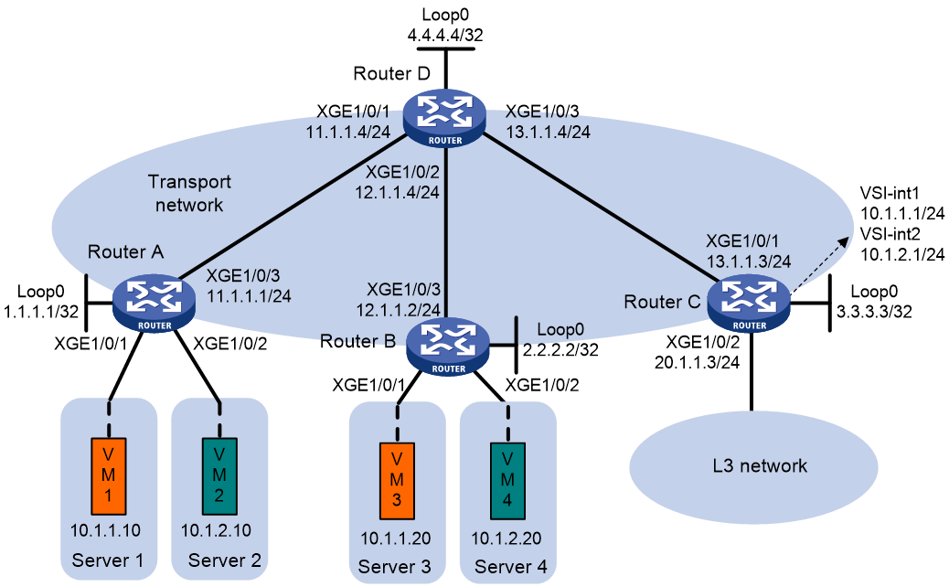
As shown in Figure 13:
· Configure VXLAN 10 and VXLAN 20 on Router A, Router B, and Router C to provide connectivity for the VMs in the VXLANs across the network sites.
· Configure Router C as a centralized EVPN gateway to provide gateway services and access to the connected Layer 3 network.
· Configure Router D as an RR to reflect BGP EVPN routes between Router A, Router B, and Router C.
Procedure
1. On VM 1 and VM 3, specify 10.1.1.1 as the gateway address. On VM 2 and VM 4, specify 10.1.2.1 as the gateway address. (Details not shown.)
2. Configure IP addresses and unicast routing settings:
# Assign IP addresses to interfaces, as shown in Figure 13. (Details not shown.)
# Configure OSPF on all transport network routers (Routers A through D) for them to reach one another. (Details not shown.)
3. Configure Router A:
# Enable L2VPN.
<RouterA> system-view
[RouterA] l2vpn enable
# Disable remote MAC address learning and remote ARP learning.
[RouterA] vxlan tunnel mac-learning disable
[RouterA] vxlan tunnel arp-learning disable
# Create an EVPN instance on VSI vpna, and configure the router to automatically generate an RD and a route target for the EVPN instance.
[RouterA] vsi vpna
[RouterA-vsi-vpna] arp suppression enable
[RouterA-vsi-vpna] evpn encapsulation vxlan
[RouterA-vsi-vpna-evpn-vxlan] route-distinguisher auto
[RouterA-vsi-vpna-evpn-vxlan] vpn-target auto
[RouterA-vsi-vpna-evpn-vxlan] quit
# Create VXLAN 10.
[RouterA-vsi-vpna] vxlan 10
[RouterA-vsi-vpna-vxlan-10] quit
[RouterA-vsi-vpna] quit
# Create an EVPN instance on VSI vpnb, and configure the router to automatically generate an RD and a route target for the EVPN instance.
[RouterA] vsi vpnb
[RouterA-vsi-vpnb] arp suppression enable
[RouterA-vsi-vpnb] evpn encapsulation vxlan
[RouterA-vsi-vpnb-evpn-vxlan] route-distinguisher auto
[RouterA-vsi-vpnb-evpn-vxlan] vpn-target auto
[RouterA-vsi-vpnb-evpn-vxlan] quit
# Create VXLAN 20.
[RouterA-vsi-vpnb] vxlan 20
[RouterA-vsi-vpnb-vxlan-20] quit
[RouterA-vsi-vpnb] quit
# Configure BGP to advertise BGP EVPN routes.
[RouterA] bgp 200
[RouterA-bgp-default] peer 4.4.4.4 as-number 200
[RouterA-bgp-default] peer 4.4.4.4 connect-interface loopback 0
[RouterA-bgp-default] address-family l2vpn evpn
[RouterA-bgp-default-evpn] peer 4.4.4.4 enable
[RouterA-bgp-default-evpn] quit
[RouterA-bgp-default] quit
# Map Ten-GigabitEthernet 0/0/6 to VSI vpna.
[RouterA] interface ten-gigabitethernet 0/0/6
[RouterA-Ten-GigabitEthernet0/0/6] xconnect vsi vpna
[RouterA-Ten-GigabitEthernet0/0/6] quit
# Map Ten-GigabitEthernet 0/0/7 to VSI vpnb.
[RouterA] interface ten-gigabitethernet 0/0/7
[RouterA-Ten-GigabitEthernet0/0/7] xconnect vsi vpnb
[RouterA-Ten-GigabitEthernet0/0/7] quit
4. Configure Router B:
# Enable L2VPN.
<RouterB> system-view
[RouterB] l2vpn enable
# Disable remote MAC address learning and remote ARP learning.
[RouterB] vxlan tunnel mac-learning disable
[RouterB] vxlan tunnel arp-learning disable
# Create an EVPN instance on VSI vpna, and configure the router to automatically generate an RD and a route target for the EVPN instance.
[RouterB] vsi vpna
[RouterB-vsi-vpna] arp suppression enable
[RouterB-vsi-vpna] evpn encapsulation vxlan
[RouterB-vsi-vpna-evpn-vxlan] route-distinguisher auto
[RouterB-vsi-vpna-evpn-vxlan] vpn-target auto
[RouterB-vsi-vpna-evpn-vxlan] quit
# Create VXLAN 10.
[RouterB-vsi-vpna] vxlan 10
[RouterB-vsi-vpna-vxlan-10] quit
[RouterB-vsi-vpna] quit
# Create an EVPN instance on VSI vpnb, and configure the router to automatically generate an RD and a route target for the EVPN instance.
[RouterB] vsi vpnb
[RouterB-vsi-vpnb] arp suppression enable
[RouterB-vsi-vpnb] evpn encapsulation vxlan
[RouterB-vsi-vpnb-evpn-vxlan] route-distinguisher auto
[RouterB-vsi-vpnb-evpn-vxlan] vpn-target auto
[RouterB-vsi-vpnb-evpn-vxlan] quit
# Create VXLAN 20.
[RouterB-vsi-vpnb] vxlan 20
[RouterB-vsi-vpnb-vxlan-20] quit
[RouterB-vsi-vpnb] quit
# Configure BGP to advertise BGP EVPN routes.
[RouterB] bgp 200
[RouterB-bgp-default] peer 4.4.4.4 as-number 200
[RouterB-bgp-default] peer 4.4.4.4 connect-interface loopback 0
[RouterB-bgp-default] address-family l2vpn evpn
[RouterB-bgp-default-evpn] peer 4.4.4.4 enable
[RouterB-bgp-default-evpn] quit
[RouterB-bgp-default] quit
# Map Ten-GigabitEthernet 0/0/6 to VSI vpna.
[RouterB] interface ten-gigabitethernet 0/0/6
[RouterB-Ten-GigabitEthernet0/0/6] xconnect vsi vpna
[RouterB-Ten-GigabitEthernet0/0/6] quit
# Map Ten-GigabitEthernet 0/0/7 to VSI vpnb.
[RouterB] interface ten-gigabitethernet 0/0/7
[RouterB-Ten-GigabitEthernet0/0/7] xconnect vsi vpnb
[RouterB-Ten-GigabitEthernet0/0/7] quit
5. Configure Router C:
# Enable L2VPN.
<RouterC> system-view
[RouterC] l2vpn enable
# Disable remote MAC address learning and remote ARP learning.
[RouterC] vxlan tunnel mac-learning disable
[RouterC] vxlan tunnel arp-learning disable
# Create an EVPN instance on VSI vpna, and configure the router to automatically generate an RD and a route target for the EVPN instance.
[RouterC] vsi vpna
[RouterC-vsi-vpna] arp suppression enable
[RouterC-vsi-vpna] evpn encapsulation vxlan
[RouterC-vsi-vpna-evpn-vxlan] route-distinguisher auto
[RouterC-vsi-vpna-evpn-vxlan] vpn-target auto
[RouterC-vsi-vpna-evpn-vxlan] quit
# Create VXLAN 10.
[RouterC-vsi-vpna] vxlan 10
[RouterC-vsi-vpna-vxlan-10] quit
[RouterC-vsi-vpna] quit
# Create an EVPN instance on VSI vpnb, and configure the router to automatically generate an RD and a route target for the EVPN instance.
[RouterC] vsi vpnb
[RouterC-vsi-vpnb] evpn encapsulation vxlan
[RouterC-vsi-vpnb-evpn-vxlan] route-distinguisher auto
[RouterC-vsi-vpnb-evpn-vxlan] vpn-target auto
[RouterC-vsi-vpnb-evpn-vxlan] quit
# Create VXLAN 20.
[RouterC-vsi-vpnb] vxlan 20
[RouterC-vsi-vpnb-vxlan-20] quit
[RouterC-vsi-vpnb] quit
# Configure BGP to advertise BGP EVPN routes.
[RouterC] bgp 200
[RouterC-bgp-default] peer 4.4.4.4 as-number 200
[RouterC-bgp-default] peer 4.4.4.4 connect-interface loopback 0
[RouterC-bgp-default] address-family l2vpn evpn
[RouterC-bgp-default-evpn] peer 4.4.4.4 enable
[RouterC-bgp-default-evpn] quit
[RouterC-bgp-default] quit
# Create VSI-interface 1 and assign the interface an IP address. The IP address will be used as the gateway address for VXLAN 10.
[RouterC] interface vsi-interface 1
[RouterC-Vsi-interface1] ip address 10.1.1.1 255.255.255.0
[RouterC-Vsi-interface1] quit
# Specify VSI-interface 1 as the gateway interface for VSI vpna.
[RouterC] vsi vpna
[RouterC-vsi-vpna] gateway vsi-interface 1
[RouterC-vsi-vpna] quit
# Create VSI-interface 2 and assign the interface an IP address. The IP address will be used as the gateway address for VXLAN 20.
[RouterC] interface vsi-interface 2
[RouterC-Vsi-interface2] ip address 10.1.2.1 255.255.255.0
[RouterC-Vsi-interface2] quit
# Specify VSI-interface 2 as the gateway interface for VSI vpnb.
[RouterC] vsi vpnb
[RouterC-vsi-vpnb] gateway vsi-interface 2
[RouterC-vsi-vpnb] quit
6. Configure Router D:
# Establish BGP connections with other transport network routers.
<RouterD> system-view
[RouterD] bgp 200
[RouterD-bgp-default] group evpn
[RouterD-bgp-default] peer 1.1.1.1 group evpn
[RouterD-bgp-default] peer 2.2.2.2 group evpn
[RouterD-bgp-default] peer 3.3.3.3 group evpn
[RouterD-bgp-default] peer evpn as-number 200
[RouterD-bgp-default] peer evpn connect-interface loopback 0
# Configure BGP to advertise BGP EVPN routes, and disable route target filtering for BGP EVPN routes.
[RouterD-bgp-default] address-family l2vpn evpn
[RouterD-bgp-default-evpn] peer evpn enable
[RouterD-bgp-default-evpn] undo policy vpn-target
# Configure Router D as an RR.
[RouterD-bgp-default-evpn] peer evpn reflect-client
[RouterD-bgp-default-evpn] quit
[RouterD-bgp-default] quit
Verifying the configuration
1. Verify the EVPN gateway settings on Router C:
# Verify that Router C has advertised MAC/IP advertisement routes and IMET routes for the gateways and received MAC/IP advertisement routes and IMET routes from Router A and Router B. (Details not shown.)
# Verify that the VXLAN tunnel interfaces are up on Router C.
[RouterC] display interface tunnel
Tunnel0
Interface index: 261
Current state: UP
Line protocol state: UP
Description: Tunnel0 Interface
Bandwidth: 64 kbps
Maximum transmission unit: 1464
Internet protocol processing: Disabled
Output queue - Urgent queuing: Size/Length/Discards 0/100/0
Output queue - Protocol queuing: Size/Length/Discards 0/500/0
Output queue - FIFO queuing: Size/Length/Discards 0/75/0
Last clearing of counters: Never
Tunnel source 3.3.3.3, destination 2.2.2.2
Tunnel protocol/transport UDP_VXLAN/IP
Last 300 seconds input rate: 0 bytes/sec, 0 bits/sec, 0 packets/sec
Last 300 seconds output rate: 0 bytes/sec, 0 bits/sec, 0 packets/sec
Input: 0 packets, 0 bytes, 0 drops
Output: 0 packets, 0 bytes, 0 drops
Tunnel1
Interface index: 262
Current state: UP
Line protocol state: UP
Description: Tunnel1 Interface
Bandwidth: 64 kbps
Maximum transmission unit: 1464
Internet protocol processing: Disabled
Output queue - Urgent queuing: Size/Length/Discards 0/100/0
Output queue - Protocol queuing: Size/Length/Discards 0/500/0
Output queue - FIFO queuing: Size/Length/Discards 0/75/0
Last clearing of counters: Never
Tunnel source 3.3.3.3, destination 1.1.1.1
Tunnel protocol/transport UDP_VXLAN/IP
Last 300 seconds input rate: 0 bytes/sec, 0 bits/sec, 0 packets/sec
Last 300 seconds output rate: 0 bytes/sec, 0 bits/sec, 0 packets/sec
Input: 277 packets, 20306 bytes, 0 drops
Output: 1099 packets, 0 bytes, 0 drops
# Verify that the VSI interfaces are up on Router C.
[RouterC] display interface vsi-interface
Vsi-interface1
Interface index: 263
Current state: UP
Line protocol state: UP
Description: Vsi-interface1 Interface
Bandwidth: 1000000 kbps
Maximum transmission unit: 1500
Internet address: 10.1.1.1/24 (primary)
IP packet frame type: Ethernet II, hardware address: 0003-0003-0003
IPv6 packet frame type: Ethernet II, hardware address: 0003-0003-0003
Physical: Unknown, baudrate: 1000000 kbps
Last clearing of counters: Never
Last 300 seconds input rate: 0 bytes/sec, 0 bits/sec, 0 packets/sec
Last 300 seconds output rate: 0 bytes/sec, 0 bits/sec, 0 packets/sec
Input: 0 packets, 0 bytes, 0 drops
Output: 0 packets, 0 bytes, 0 drops
Vsi-interface2
Interface index: 264
Current state: UP
Line protocol state: UP
Description: Vsi-interface2 Interface
Bandwidth: 1000000 kbps
Maximum transmission unit: 1500
Internet address: 10.1.2.1/24 (primary)
IP packet frame type: Ethernet II, hardware address: 0003-0003-0003
IPv6 packet frame type: Ethernet II, hardware address: 0003-0003-0003
Physical: Unknown, baudrate: 1000000 kbps
Last clearing of counters: Never
Last 300 seconds input rate: 0 bytes/sec, 0 bits/sec, 0 packets/sec
Last 300 seconds output rate: 0 bytes/sec, 0 bits/sec, 0 packets/sec
Input: 0 packets, 0 bytes, 0 drops
Output: 0 packets, 0 bytes, 0 drops
# Verify that the VXLAN tunnels have been assigned to the VXLANs, and the VSI interfaces are the gateway interfaces of their respective VXLANs.
[RouterC] display l2vpn vsi verbose
VSI Name: vpna
VSI Index : 0
VSI State : Up
MTU : 1500
Bandwidth : -
Broadcast Restrain : -
Multicast Restrain : -
Unknown Unicast Restrain: -
MAC Learning : -
MAC Table Limit : -
MAC Learning rate : -
Drop Unknown : -
Flooding : Enabled
Statistics : Disabled
Gateway Interface : VSI-interface 1
VXLAN ID : 10
Tunnels:
Tunnel Name Link ID State Type Flood Proxy
Tunnel0 0x5000000 UP Auto Disabled
Tunnel1 0x5000001 UP Auto Disabled
VSI Name: vpnb
VSI Index : 1
VSI State : Up
MTU : 1500
Bandwidth : -
Broadcast Restrain : -
Multicast Restrain : -
Unknown Unicast Restrain: -
MAC Learning : -
MAC Table Limit : -
MAC Learning rate : -
Drop Unknown : -
Flooding : Enabled
Statistics : Disabled
Gateway Interface : VSI-interface 2
VXLAN ID : 20
Tunnels:
Tunnel Name Link ID State Type Flood Proxy
Tunnel0 0x5000000 UP Auto Disabled
Tunnel1 0x5000001 UP Auto Disabled
# Verify that Router C has created EVPN ARP entries for the VMs.
[RouterC] display evpn route arp
Flags: D - Dynamic B - BGP L - Local active
G - Gateway S - Static M - Mapping
Public instance Interface: Vsi-interface1
IP address MAC address Router MAC VSI index Flags
10.1.1.1 0003-0003-0003 - 0 GL
10.1.1.10 0000-1234-0001 - 0 B
10.1.1.20 0000-1234-0003 - 0 B
Public instance Interface: Vsi-interface2
IP address MAC address Router MAC VSI index Flags
10.1.2.1 0005-0005-0005 - 1 GL
10.1.2.10 0000-1234-0002 - 1 B
10.1.2.20 0000-1234-0004 - 1 B
# Verify that Router C has created FIB entries for the VMs.
[RouterC] display fib 10.1.1.10
Destination count: 1 FIB entry count: 1
Flag:
U:Usable G:Gateway H:Host B:Blackhole D:Dynamic S:Static
R:Relay F:FRR
Destination/Mask Nexthop Flag OutInterface/Token Label
10.1.1.10/32 10.1.1.10 UH Vsi1 Null
2. Verify that VM 1, VM 2, VM 3, and VM 4 can communicate with one another. (Details not shown.)
Example: Configuring distributed IPv4 EVPN gateways in symmetric IRB mode
Network configuration
As shown in Figure 14:
· Configure VXLAN 10 and VXLAN 20 on Router A and Router B to provide connectivity for the VMs in the VXLANs across the network sites.
· Configure Router A and Router B as distributed EVPN gateways to provide gateway services in symmetric IRB mode. Configure Router C as a border gateway to provide access to the connected Layer 3 network.
· Configure Router D as an RR to reflect BGP EVPN routes between Router A, Router B, and Router C.
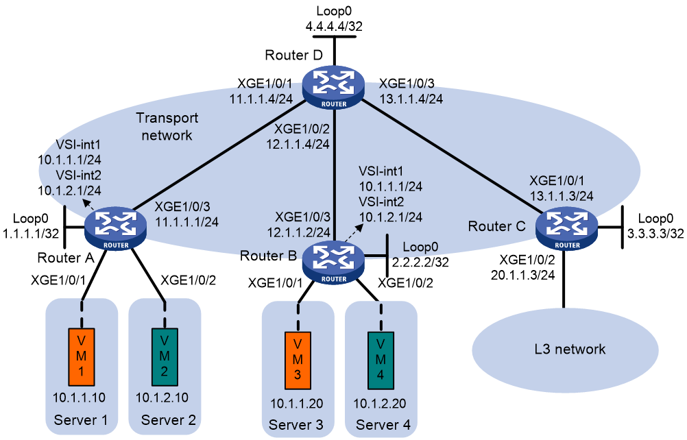
Procedure
1. On VM 1 and VM 3, specify 10.1.1.1 as the gateway address. On VM 2 and VM 4, specify 10.1.2.1 as the gateway address. (Details not shown.)
2. Configure IP addresses and unicast routing settings:
# Assign IP addresses to interfaces, as shown in Figure 14. (Details not shown.)
# Configure OSPF on all transport network routers (Routers A through D) for them to reach one another. (Details not shown.)
3. Configure Router A:
# Enable L2VPN.
<RouterA> system-view
[RouterA] l2vpn enable
# Disable remote MAC address learning and remote ARP learning.
[RouterA] vxlan tunnel mac-learning disable
[RouterA] vxlan tunnel arp-learning disable
# Create an EVPN instance on VSI vpna, and configure the router to automatically generate an RD and a route target for the EVPN instance.
[RouterA] vsi vpna
[RouterA-vsi-vpna] evpn encapsulation vxlan
[RouterA-vsi-vpna-evpn-vxlan] route-distinguisher auto
[RouterA-vsi-vpna-evpn-vxlan] vpn-target auto
[RouterA-vsi-vpna-evpn-vxlan] quit
# Create VXLAN 10.
[RouterA-vsi-vpna] vxlan 10
[RouterA-vsi-vpna-vxlan-10] quit
[RouterA-vsi-vpna] quit
# Create an EVPN instance on VSI vpnb, and configure the router to automatically generate an RD and a route target for the EVPN instance.
[RouterA] vsi vpnb
[RouterA-vsi-vpnb] evpn encapsulation vxlan
[RouterA-vsi-vpnb-evpn-vxlan] route-distinguisher auto
[RouterA-vsi-vpnb-evpn-vxlan] vpn-target auto
[RouterA-vsi-vpnb-evpn-vxlan] quit
# Create VXLAN 20.
[RouterA-vsi-vpnb] vxlan 20
[RouterA-vsi-vpnb-vxlan-20] quit
[RouterA-vsi-vpnb] quit
# Configure BGP to advertise BGP EVPN routes.
[RouterA] bgp 200
[RouterA-bgp-default] peer 4.4.4.4 as-number 200
[RouterA-bgp-default] peer 4.4.4.4 connect-interface loopback 0
[RouterA-bgp-default] address-family l2vpn evpn
[RouterA-bgp-default-evpn] peer 4.4.4.4 enable
[RouterA-bgp-default-evpn] quit
[RouterA-bgp-default] quit
# Map Ten-GigabitEthernet 0/0/6 to VSI vpna.
[RouterA] interface ten-gigabitethernet 0/0/6
[RouterA-Ten-GigabitEthernet0/0/6] xconnect vsi vpna
[RouterA-Ten-GigabitEthernet0/0/6] quit
# Map Ten-GigabitEthernet 0/0/7 to VSI vpnb.
[RouterA] interface ten-gigabitethernet 0/0/7
[RouterA-Ten-GigabitEthernet0/0/7] xconnect vsi vpnb
[RouterA-Ten-GigabitEthernet0/0/7] quit
# Configure RD and route target settings for VPN instance vpna.
[RouterA] ip vpn-instance vpna
[RouterA-vpn-instance-vpna] route-distinguisher 1:1
[RouterA-vpn-instance-vpna] address-family ipv4
[RouterA-vpn-ipv4-vpna] vpn-target 2:2
[RouterA-vpn-ipv4-vpna] quit
[RouterA-vpn-instance-vpna] address-family evpn
[RouterA-vpn-evpn-vpna] vpn-target 1:1
[RouterA-vpn-evpn-vpna] quit
[RouterA-vpn-instance-vpna] quit
# Configure VSI-interface 1.
[RouterA] interface vsi-interface 1
[RouterA-Vsi-interface1] ip binding vpn-instance vpna
[RouterA-Vsi-interface1] ip address 10.1.1.1 255.255.255.0
[RouterA-Vsi-interface1] mac-address 1-1-1
[RouterA-Vsi-interface1] distributed-gateway local
[RouterA-Vsi-interface1] local-proxy-arp enable
[RouterA-Vsi-interface1] quit
# Configure VSI-interface 2.
[RouterA] interface vsi-interface 2
[RouterA-Vsi-interface2] ip binding vpn-instance vpna
[RouterA-Vsi-interface2] ip address 10.1.2.1 255.255.255.0
[RouterA-Vsi-interface2] mac-address 2-2-2
[RouterA-Vsi-interface2] distributed-gateway local
[RouterA-Vsi-interface2] local-proxy-arp enable
[RouterA-Vsi-interface2] quit
# Associate VSI-interface 3 with VPN instance vpna, and configure the L3 VXLAN ID as 1000 for the VPN instance.
[RouterA] interface vsi-interface 3
[RouterA-Vsi-interface3] ip binding vpn-instance vpna
[RouterA-Vsi-interface3] l3-vni 1000
[RouterA-Vsi-interface3] quit
# Specify VSI-interface 1 as the gateway interface for VSI vpna.
[RouterA] vsi vpna
[RouterA-vsi-vpna] gateway vsi-interface 1
[RouterA-vsi-vpna] quit
# Specify VSI-interface 2 as the gateway interface for VSI vpnb.
[RouterA] vsi vpnb
[RouterA-vsi-vpnb] gateway vsi-interface 2
[RouterA-vsi-vpnb] quit
4. Configure Router B:
# Enable L2VPN.
<RouterB> system-view
[RouterB] l2vpn enable
# Disable remote MAC address learning and remote ARP learning.
[RouterB] vxlan tunnel mac-learning disable
[RouterB] vxlan tunnel arp-learning disable
# Create an EVPN instance on VSI vpna, and configure the router to automatically generate an RD and a route target for the EVPN instance.
[RouterB] vsi vpna
[RouterB-vsi-vpna] evpn encapsulation vxlan
[RouterB-vsi-vpna-evpn-vxlan] route-distinguisher auto
[RouterB-vsi-vpna-evpn-vxlan] vpn-target auto
[RouterB-vsi-vpna-evpn-vxlan] quit
# Create VXLAN 10.
[RouterB-vsi-vpna] vxlan 10
[RouterB-vsi-vpna-vxlan-10] quit
[RouterB-vsi-vpna] quit
# Create an EVPN instance on VSI vpnb, and configure the router to automatically generate an RD and a route target for the EVPN instance.
[RouterB] vsi vpnb
[RouterB-vsi-vpnb] evpn encapsulation vxlan
[RouterB-vsi-vpnb-evpn-vxlan] route-distinguisher auto
[RouterB-vsi-vpnb-evpn-vxlan] vpn-target auto
[RouterB-vsi-vpnb-evpn-vxlan] quit
# Create VXLAN 20.
[RouterB-vsi-vpnb] vxlan 20
[RouterB-vsi-vpnb-vxlan-20] quit
[RouterB-vsi-vpnb] quit
# Configure BGP to advertise BGP EVPN routes.
[RouterB] bgp 200
[RouterB-bgp-default] peer 4.4.4.4 as-number 200
[RouterB-bgp-default] peer 4.4.4.4 connect-interface loopback 0
[RouterB-bgp-default] address-family l2vpn evpn
[RouterB-bgp-default-evpn] peer 4.4.4.4 enable
[RouterB-bgp-default-evpn] quit
[RouterB-bgp-default] quit
# Map Ten-GigabitEthernet 0/0/6 to VSI vpna.
[RouterB] interface ten-gigabitethernet 0/0/6
[RouterB-Ten-GigabitEthernet0/0/6] xconnect vsi vpna
[RouterB-Ten-GigabitEthernet0/0/6] quit
# Map Ten-GigabitEthernet 0/0/7 to VSI vpnb.
[RouterB] interface ten-gigabitethernet 0/0/7
[RouterB-Ten-GigabitEthernet0/0/7] xconnect vsi vpnb
[RouterB-Ten-GigabitEthernet0/0/7] quit
# Configure RD and route target settings for VPN instance vpna.
[RouterB] ip vpn-instance vpna
[RouterB-vpn-instance-vpna] route-distinguisher 1:1
[RouterB-vpn-instance-vpna] address-family ipv4
[RouterB-vpn-ipv4-vpna] vpn-target 2:2
[RouterB-vpn-ipv4-vpna] quit
[RouterB-vpn-instance-vpna] address-family evpn
[RouterB-vpn-evpn-vpna] vpn-target 1:1
[RouterB-vpn-evpn-vpna] quit
[RouterB-vpn-instance-vpna] quit
# Configure VSI-interface 1.
[RouterB] interface vsi-interface 1
[RouterB-Vsi-interface1] ip binding vpn-instance vpna
[RouterB-Vsi-interface1] ip address 10.1.1.1 255.255.255.0
[RouterB-Vsi-interface1] mac-address 1-1-1
[RouterB-Vsi-interface1] distributed-gateway local
[RouterB-Vsi-interface1] local-proxy-arp enable
[RouterB-Vsi-interface1] quit
# Configure VSI-interface 2.
[RouterB] interface vsi-interface 2
[RouterB-Vsi-interface2] ip binding vpn-instance vpna
[RouterB-Vsi-interface2] ip address 10.1.2.1 255.255.255.0
[RouterB-Vsi-interface2] mac-address 2-2-2
[RouterB-Vsi-interface2] distributed-gateway local
[RouterB-Vsi-interface2] local-proxy-arp enable
[RouterB-Vsi-interface2] quit
# Associate VSI-interface 3 with VPN instance vpna, and configure the L3 VXLAN ID as 1000 for the VPN instance.
[RouterB] interface vsi-interface 3
[RouterB-Vsi-interface3] ip binding vpn-instance vpna
[RouterB-Vsi-interface3] l3-vni 1000
[RouterB-Vsi-interface3] quit
# Specify VSI-interface 1 as the gateway interface for VSI vpna.
[RouterB] vsi vpna
[RouterB-vsi-vpna] gateway vsi-interface 1
[RouterB-vsi-vpna] quit
# Specify VSI-interface 2 as the gateway interface for VSI vpnb.
[RouterB] vsi vpnb
[RouterB-vsi-vpnb] gateway vsi-interface 2
[RouterB-vsi-vpnb] quit
5. Configure Router C:
# Enable L2VPN.
<RouterC> system-view
[RouterC] l2vpn enable
# Disable remote MAC address learning and remote ARP learning.
[RouterC] vxlan tunnel mac-learning disable
[RouterC] vxlan tunnel arp-learning disable
# Configure BGP to advertise BGP EVPN routes.
[RouterC] bgp 200
[RouterC-bgp-default] peer 4.4.4.4 as-number 200
[RouterC-bgp-default] peer 4.4.4.4 connect-interface loopback 0
[RouterC-bgp-default] address-family l2vpn evpn
[RouterC-bgp-default-evpn] peer 4.4.4.4 enable
[RouterC-bgp-default-evpn] quit
[RouterC-bgp-default] quit
# Configure RD and route target settings for VPN instance vpna.
[RouterC] ip vpn-instance vpna
[RouterC-vpn-instance-vpna] route-distinguisher 1:1
[RouterC-vpn-instance-vpna] address-family ipv4
[RouterC-vpn-ipv4-vpna] vpn-target 2:2
[RouterC-vpn-ipv4-vpna] quit
[RouterC-vpn-instance-vpna] address-family evpn
[RouterC-vpn-evpn-vpna] vpn-target 1:1
[RouterC-vpn-evpn-vpna] quit
[RouterC-vpn-instance-vpna] quit
# Associate VSI-interface 3 with VPN instance vpna, and configure the L3 VXLAN ID as 1000 for the VPN instance.
[RouterC] interface vsi-interface 3
[RouterC-Vsi-interface3] ip binding vpn-instance vpna
[RouterC-Vsi-interface3] l3-vni 1000
[RouterC-Vsi-interface3] quit
# Configure a default route. The next hop is the IP address of a device in the Layer 3 network.
[RouterC] ip route-static vpn-instance vpna 0.0.0.0 0 20.1.1.100
# Import the default route to the BGP IPv4 unicast routing table of VPN instance vpna.
[RouterC] bgp 200
[RouterC-bgp-default] ip vpn-instance vpna
[RouterC-bgp-default-vpna] address-family ipv4 unicast
[RouterC-bgp-default-ipv4-vpna] default-route imported
[RouterC-bgp-default-ipv4-vpna] import-route static
[RouterC-bgp-default-ipv4-vpna] quit
[RouterC-bgp-default-vpna] quit
[RouterC-bgp-default] quit
# Associate Ten-GigabitEthernet 0/0/7 with VPN instance vpna. Ten-GigabitEthernet 0/0/7 provides access to the Layer 3 network connected to Router C.
[RouterC] interface ten-gigabitethernet 0/0/7
[RouterC-Ten-GigabitEthernet0/0/7] ip binding vpn-instance vpna
[RouterC-Ten-GigabitEthernet0/0/7] ip address 20.1.1.3 24
[RouterC-Ten-GigabitEthernet0/0/7] quit
6. Configure Router D:
# Establish BGP connections with other transport network routers.
<RouterD> system-view
[RouterD] bgp 200
[RouterD-bgp-default] group evpn
[RouterD-bgp-default] peer 1.1.1.1 group evpn
[RouterD-bgp-default] peer 2.2.2.2 group evpn
[RouterD-bgp-default] peer 3.3.3.3 group evpn
[RouterD-bgp-default] peer evpn as-number 200
[RouterD-bgp-default] peer evpn connect-interface loopback 0
# Configure BGP to advertise BGP EVPN routes, and disable route target filtering for BGP EVPN routes.
[RouterD-bgp-default] address-family l2vpn evpn
[RouterD-bgp-default-evpn] peer evpn enable
[RouterD-bgp-default-evpn] undo policy vpn-target
# Configure Router D as an RR.
[RouterD-bgp-default-evpn] peer evpn reflect-client
[RouterD-bgp-default-evpn] quit
[RouterD-bgp-default] quit
Verifying the configuration
1. Verify the distributed EVPN gateway settings on Router A:
# Verify that Router A has advertised the IP prefix advertisement routes for the gateways and the MAC/IP advertisement routes and IMET routes for each VSI. Verify that Router A has received the IP prefix advertisement routes for the gateways and the MAC/IP advertisement routes and IMET routes for each VSI from Router B. (Details not shown.)
# Verify that the VXLAN tunnel interfaces are up on Router A. (This example uses Tunnel 0.)
[RouterA] display interface tunnel 0
Tunnel0
Interface index: 261
Current state: UP
Line protocol state: UP
Description: Tunnel0 Interface
Bandwidth: 64 kbps
Maximum transmission unit: 1464
Internet protocol processing: Disabled
Output queue - Urgent queuing: Size/Length/Discards 0/100/0
Output queue - Protocol queuing: Size/Length/Discards 0/500/0
Output queue - FIFO queuing: Size/Length/Discards 0/75/0
Last clearing of counters: Never
Tunnel source 1.1.1.1, destination 2.2.2.2
Tunnel protocol/transport UDP_VXLAN/IP
Last 300 seconds input rate: 0 bytes/sec, 0 bits/sec, 0 packets/sec
Last 300 seconds output rate: 0 bytes/sec, 0 bits/sec, 0 packets/sec
Input: 0 packets, 0 bytes, 0 drops
Output: 0 packets, 0 bytes, 0 drops
# Verify that the VSI interfaces are up on Router A. (This example uses VSI-interface 1.)
[RouterA] display interface vsi-interface 1
Vsi-interface1
Interface index: 262
Current state: UP
Line protocol state: UP
Description: Vsi-interface1 Interface
Bandwidth: 1000000 kbps
Maximum transmission unit: 1500
Internet address: 10.1.1.1/24 (primary)
IP packet frame type: Ethernet II, hardware address: 0003-0003-0003
IPv6 packet frame type: Ethernet II, hardware address: 0003-0003-0003
Physical: Unknown, baudrate: 1000000 kbps
Last clearing of counters: Never
Last 300 seconds input rate: 0 bytes/sec, 0 bits/sec, 0 packets/sec
Last 300 seconds output rate: 0 bytes/sec, 0 bits/sec, 0 packets/sec
Input: 0 packets, 0 bytes, 0 drops
Output: 0 packets, 0 bytes, 0 drops
# Verify that the VXLAN tunnels have been assigned to the VXLANs, and the VSI interfaces are the gateway interfaces of their respective VXLANs.
[RouterA] display l2vpn vsi verbose
VSI Name: Auto_L3VNI1000_3
VSI Index : 1
VSI State : Down
MTU : 1500
Bandwidth : -
Broadcast Restrain : -
Multicast Restrain : -
Unknown Unicast Restrain: -
MAC Learning : -
MAC Table Limit : -
MAC Learning rate : -
Drop Unknown : -
Flooding : Enabled
Statistics : Disabled
Gateway Interface : VSI-interface 3
VXLAN ID : 1000
VSI Name: vpna
VSI Index : 0
VSI State : Up
MTU : 1500
Bandwidth : -
Broadcast Restrain : -
Multicast Restrain : -
Unknown Unicast Restrain: -
MAC Learning : -
MAC Table Limit : -
MAC Learning rate : -
Drop Unknown : -
Flooding : Enabled
Statistics : Disabled
Gateway Interface : VSI-interface 1
VXLAN ID : 10
ACs:
AC Link ID State
XGE0/0/6 0x0 Up
VSI Name: vpnb
VSI Index : 2
VSI State : Up
MTU : 1500
Bandwidth : -
Broadcast Restrain : -
Multicast Restrain : -
Unknown Unicast Restrain: -
MAC Learning : -
MAC Table Limit : -
MAC Learning rate : -
Drop Unknown : -
Flooding : Enabled
Statistics : Disabled
Gateway Interface : VSI-interface 2
VXLAN ID : 20
ACs:
AC Link ID State
XGE0/0/7 0x1 Up
# Verify that Router A has created ARP entries for the VMs.
[RouterA] display arp
Type: S-Static D-Dynamic O-Openflow R-Rule M-Multiport I-Invalid
IP address MAC address VLAN/VSI name Interface Aging Type
10.1.1.10 0000-1234-0001 0 XGE0/0/6 20 D
10.1.2.10 0000-1234-0002 0 XGE0/0/7 19 D
2.2.2.2 a0ce-5e24-0100 1 Tunnel0 -- R
# Verify that Router A has created EVPN ARP entries for the local VMs.
[RouterA] display evpn route arp
Flags: D - Dynamic B - BGP L - Local active
G - Gateway S - Static M - Mapping
VPN instance:vpna Interface:Vsi-interface1
IP address MAC address Router MAC VSI Index Flags
10.1.1.1 0001-0001-0001 a0ce-7e40-0400 0 GL
10.1.1.10 0000-1234-0001 a0ce-7e40-0400 0 DL
10.1.2.10 0000-1234-0002 a0ce-7e40-0400 0 DL
10.1.1.20 0000-1234-0003 a0ce-7e40-0400 0 B
10.1.2.20 0000-1234-0004 a0ce-7e40-0400 0 B
2. Verify that VM 1, VM 2, VM 3, and VM 4 can communicate with one another. (Details not shown.)
Example: Configuring distributed IPv6 EVPN gateways in symmetric IRB mode
Network configuration
As shown in Figure 15:
· Configure VXLAN 10 and VXLAN 20 on Router A and Router B to provide connectivity for the VMs in the VXLANs across the network sites.
· Configure Router A and Router B as distributed EVPN gateways to provide gateway services in symmetric IRB mode. Configure Router C as a border gateway to provide access to the connected Layer 3 network.
· Configure Router D as an RR to reflect BGP EVPN routes between Router A, Router B, and Router C.
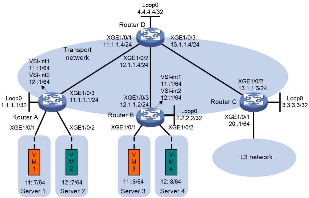
Procedure
1. On VM 1 and VM 3, specify 11::1 as the gateway address. On VM 2 and VM 4, specify 12::1 as the gateway address. (Details not shown.)
2. Configure IP addresses and unicast routing settings:
# Assign IP addresses to interfaces, as shown in Figure 15. (Details not shown.)
# Configure OSPF on all transport network routers (Routers A through D) for them to reach one another. (Details not shown.)
3. Configure Router A:
# Enable L2VPN.
<RouterA> system-view
[RouterA] l2vpn enable
# Disable remote MAC address learning and remote ND learning.
[RouterA] vxlan tunnel mac-learning disable
[RouterA] vxlan tunnel nd-learning disable
# Create an EVPN instance on VSI vpna, and configure the router to automatically generate an RD and a route target for the EVPN instance.
[RouterA] vsi vpna
[RouterA-vsi-vpna] evpn encapsulation vxlan
[RouterA-vsi-vpna-evpn-vxlan] route-distinguisher auto
[RouterA-vsi-vpna-evpn-vxlan] vpn-target auto
[RouterA-vsi-vpna-evpn-vxlan] quit
# Create VXLAN 10.
[RouterA-vsi-vpna] vxlan 10
[RouterA-vsi-vpna-vxlan-10] quit
[RouterA-vsi-vpna] quit
# Create an EVPN instance on VSI vpnb, and configure the router to automatically generate an RD and a route target for the EVPN instance.
[RouterA] vsi vpnb
[RouterA-vsi-vpnb] evpn encapsulation vxlan
[RouterA-vsi-vpnb-evpn-vxlan] route-distinguisher auto
[RouterA-vsi-vpnb-evpn-vxlan] vpn-target auto
[RouterA-vsi-vpnb-evpn-vxlan] quit
# Create VXLAN 20.
[RouterA-vsi-vpnb] vxlan 20
[RouterA-vsi-vpnb-vxlan-20] quit
[RouterA-vsi-vpnb] quit
# Configure BGP to advertise BGP EVPN routes.
[RouterA] bgp 200
[RouterA-bgp-default] peer 4.4.4.4 as-number 200
[RouterA-bgp-default] peer 4.4.4.4 connect-interface loopback 0
[RouterA-bgp-default] address-family l2vpn evpn
[RouterA-bgp-default-evpn] peer 4.4.4.4 enable
[RouterA-bgp-default-evpn] quit
[RouterA-bgp-default] quit
# Map Ten-GigabitEthernet 0/0/6 to VSI vpna.
[RouterA] interface ten-gigabitethernet 0/0/6
[RouterA-Ten-GigabitEthernet0/0/6] xconnect vsi vpna
[RouterA-Ten-GigabitEthernet0/0/6] quit
# Map Ten-GigabitEthernet 0/0/7 to VSI vpnb.
[RouterA] interface ten-gigabitethernet 0/0/7
[RouterA-Ten-GigabitEthernet0/0/7] xconnect vsi vpnb
[RouterA-Ten-GigabitEthernet0/0/7] quit
# Configure RD and route target settings for VPN instance vpna.
[RouterA] ip vpn-instance vpna
[RouterA-vpn-instance-vpna] route-distinguisher 1:1
[RouterA-vpn-instance-vpna] address-family ipv6
[RouterA-vpn-ipv6-vpna] vpn-target 2:2
[RouterA-vpn-ipv6-vpna] quit
[RouterA-vpn-instance-vpna] address-family evpn
[RouterA-vpn-evpn-vpna] vpn-target 1:1
[RouterA-vpn-evpn-vpna] quit
[RouterA-vpn-instance-vpna] quit
# Configure VSI-interface 1.
[RouterA] interface vsi-interface 1
[RouterA-Vsi-interface1] ip binding vpn-instance vpna
[RouterA-Vsi-interface1] ipv6 address 11::1 64
[RouterA-Vsi-interface1] mac-address 1-1-1
[RouterA-Vsi-interface1] distributed-gateway local
[RouterA-Vsi-interface1] local-proxy-nd enable
[RouterA-Vsi-interface1] quit
# Configure VSI-interface 2.
[RouterA] interface vsi-interface 2
[RouterA-Vsi-interface2] ip binding vpn-instance vpna
[RouterA-Vsi-interface2] ipv6 address 12::1 64
[RouterA-Vsi-interface2] mac-address 2-2-2
[RouterA-Vsi-interface2] distributed-gateway local
[RouterA-Vsi-interface2] local-proxy-nd enable
[RouterA-Vsi-interface2] quit
# Associate VSI-interface 3 with VPN instance vpna, and configure the L3 VXLAN ID as 1000 for the VPN instance.
[RouterA] interface vsi-interface 3
[RouterA-Vsi-interface3] ip binding vpn-instance vpna
[RouterA-Vsi-interface3] ipv6 address auto link-local
[RouterA-Vsi-interface3] l3-vni 1000
[RouterA-Vsi-interface3] quit
# Specify VSI-interface 1 as the gateway interface for VSI vpna.
[RouterA] vsi vpna
[RouterA-vsi-vpna] gateway vsi-interface 1
[RouterA-vsi-vpna] quit
# Specify VSI-interface 2 as the gateway interface for VSI vpnb.
[RouterA] vsi vpnb
[RouterA-vsi-vpnb] gateway vsi-interface 2
[RouterA-vsi-vpnb] quit
4. Configure Router B:
# Enable L2VPN.
<RouterB> system-view
[RouterB] l2vpn enable
# Disable remote MAC address learning and remote ND learning.
[RouterB] vxlan tunnel mac-learning disable
[RouterB] vxlan tunnel nd-learning disable
# Create an EVPN instance on VSI vpna, and configure the router to automatically generate an RD and a route target for the EVPN instance.
[RouterB] vsi vpna
[RouterB-vsi-vpna] evpn encapsulation vxlan
[RouterB-vsi-vpna-evpn-vxlan] route-distinguisher auto
[RouterB-vsi-vpna-evpn-vxlan] vpn-target auto
[RouterB-vsi-vpna-evpn-vxlan] quit
# Create VXLAN 10.
[RouterB-vsi-vpna] vxlan 10
[RouterB-vsi-vpna-vxlan-10] quit
[RouterB-vsi-vpna] quit
# Create an EVPN instance on VSI vpnb, and configure the router to automatically generate an RD and a route target for the EVPN instance.
[RouterB] vsi vpnb
[RouterB-vsi-vpnb] evpn encapsulation vxlan
[RouterB-vsi-vpnb-evpn-vxlan] route-distinguisher auto
[RouterB-vsi-vpnb-evpn-vxlan] vpn-target auto
[RouterB-vsi-vpnb-evpn-vxlan] quit
# Create VXLAN 20.
[RouterB-vsi-vpnb] vxlan 20
[RouterB-vsi-vpnb-vxlan-20] quit
[RouterB-vsi-vpnb] quit
# Configure BGP to advertise BGP EVPN routes.
[RouterB] bgp 200
[RouterB-bgp-default] peer 4.4.4.4 as-number 200
[RouterB-bgp-default] peer 4.4.4.4 connect-interface loopback 0
[RouterB-bgp-default] address-family l2vpn evpn
[RouterB-bgp-default-evpn] peer 4.4.4.4 enable
[RouterB-bgp-default-evpn] quit
[RouterB-bgp-default] quit
# Map Ten-GigabitEthernet 0/0/6 to VSI vpna.
[RouterB] interface ten-gigabitethernet 0/0/6
[RouterB-Ten-GigabitEthernet0/0/6] xconnect vsi vpna
[RouterB-Ten-GigabitEthernet0/0/6] quit
# Map Ten-GigabitEthernet 0/0/7 to VSI vpnb.
[RouterB] interface ten-gigabitethernet 0/0/7
[RouterB-Ten-GigabitEthernet0/0/7] xconnect vsi vpnb
[RouterB-Ten-GigabitEthernet0/0/7] quit
# Configure RD and route target settings for VPN instance vpna.
[RouterB] ip vpn-instance vpna
[RouterB-vpn-instance-vpna] route-distinguisher 1:1
[RouterB-vpn-instance-vpna] address-family ipv6
[RouterB-vpn-ipv6-vpna] vpn-target 2:2
[RouterB-vpn-ipv6-vpna] quit
[RouterB-vpn-instance-vpna] address-family evpn
[RouterB-vpn-evpn-vpna] vpn-target 1:1
[RouterB-vpn-evpn-vpna] quit
[RouterB-vpn-instance-vpna] quit
# Configure VSI-interface 1.
[RouterB] interface vsi-interface 1
[RouterB-Vsi-interface1] ip binding vpn-instance vpna
[RouterB-Vsi-interface1] ipv6 address 11::1 64
[RouterB-Vsi-interface1] mac-address 1-1-1
[RouterB-Vsi-interface1] distributed-gateway local
[RouterB-Vsi-interface1] local-proxy-nd enable
[RouterB-Vsi-interface1] quit
# Configure VSI-interface 2.
[RouterB] interface vsi-interface 2
[RouterB-Vsi-interface2] ip binding vpn-instance vpna
[RouterB-Vsi-interface2] ipv6 address 12::1 64
[RouterB-Vsi-interface2] mac-address 2-2-2
[RouterB-Vsi-interface2] distributed-gateway local
[RouterB-Vsi-interface2] local-proxy-nd enable
[RouterB-Vsi-interface2] quit
# Associate VSI-interface 3 with VPN instance vpna, and configure the L3 VXLAN ID as 1000 for the VPN instance.
[RouterB] interface vsi-interface 3
[RouterB-Vsi-interface3] ip binding vpn-instance vpna
[RouterB-Vsi-interface3] ipv6 address auto link-local
[RouterB-Vsi-interface3] l3-vni 1000
[RouterB-Vsi-interface3] quit
# Specify VSI-interface 1 as the gateway interface for VSI vpna.
[RouterB] vsi vpna
[RouterB-vsi-vpna] gateway vsi-interface 1
[RouterB-vsi-vpna] quit
# Specify VSI-interface 2 as the gateway interface for VSI vpnb.
[RouterB] vsi vpnb
[RouterB-vsi-vpnb] gateway vsi-interface 2
[RouterB-vsi-vpnb] quit
5. Configure Router C:
# Enable L2VPN.
<RouterC> system-view
[RouterC] l2vpn enable
# Disable remote MAC address learning and remote ND learning.
[RouterC] vxlan tunnel mac-learning disable
[RouterC] vxlan tunnel nd-learning disable
# Configure BGP to advertise BGP EVPN routes.
[RouterC] bgp 200
[RouterC-bgp-default] peer 4.4.4.4 as-number 200
[RouterC-bgp-default] peer 4.4.4.4 connect-interface loopback 0
[RouterC-bgp-default] address-family l2vpn evpn
[RouterC-bgp-default-evpn] peer 4.4.4.4 enable
[RouterC-bgp-default-evpn] quit
[RouterC-bgp-default] quit
# Configure RD and route target settings for VPN instance vpna.
[RouterC] ip vpn-instance vpna
[RouterC-vpn-instance-vpna] route-distinguisher 1:1
[RouterC-vpn-instance-vpna] address-family ipv6
[RouterC-vpn-ipv6-vpna] vpn-target 2:2
[RouterC-vpn-ipv6-vpna] quit
[RouterC-vpn-instance-vpna] address-family evpn
[RouterC-vpn-evpn-vpna] vpn-target 1:1
[RouterC-vpn-evpn-vpna] quit
[RouterC-vpn-instance-vpna] quit
# Associate VSI-interface 3 with VPN instance vpna, and configure the L3 VXLAN ID as 1000 for the VPN instance.
[RouterC] interface vsi-interface 3
[RouterC-Vsi-interface3] ip binding vpn-instance vpna
[RouterC-Vsi-interface3] ipv6 address auto link-local
[RouterC-Vsi-interface3] l3-vni 1000
[RouterC-Vsi-interface3] quit
# Configure a default route. The next hop is the IP address of a device in the Layer 3 network.
[RouterC] ipv6 route-static vpn-instance vpna :: 0 20::100
# Import the default route to the BGP IPv6 unicast routing table of VPN instance vpna.
[RouterC] bgp 200
[RouterC-bgp-default] ip vpn-instance vpna
[RouterC-bgp-default-vpna] address-family ipv6 unicast
[RouterC-bgp-default-ipv6-vpna] default-route imported
[RouterC-bgp-default-ipv6-vpna] import-route static
[RouterC-bgp-default-ipv6-vpna] quit
[RouterC-bgp-default-vpna] quit
[RouterC-bgp-default] quit
# Associate VLAN-interface 20 with VPN instance vpna.
[RouterC] interface vlan-interface 20
[RouterC-Vlan-interface20] ip binding vpn-instance vpna
[RouterC-Vlan-interface20] ipv6 address 20::1 64
[RouterC-Vlan-interface20] quit
6. Configure Router D:
# Establish BGP connections with other transport network routers.
<RouterD> system-view
[RouterD] bgp 200
[RouterD-bgp-default] group evpn
[RouterD-bgp-default] peer 1.1.1.1 group evpn
[RouterD-bgp-default] peer 2.2.2.2 group evpn
[RouterD-bgp-default] peer 3.3.3.3 group evpn
[RouterD-bgp-default] peer evpn as-number 200
[RouterD-bgp-default] peer evpn connect-interface loopback 0
# Configure BGP to advertise BGP EVPN routes, and disable route target filtering for BGP EVPN routes.
[RouterD-bgp-default] address-family l2vpn evpn
[RouterD-bgp-default-evpn] peer evpn enable
[RouterD-bgp-default-evpn] undo policy vpn-target
# Configure Router D as an RR.
[RouterD-bgp-default-evpn] peer evpn reflect-client
[RouterD-bgp-default-evpn] quit
[RouterD-bgp-default] quit
Verifying the configuration
1. Verify the distributed EVPN gateway settings on Router A:
# Verify that Router A has advertised the IP prefix advertisement routes for the gateways and the MAC/IP advertisement routes and IMET routes for each VSI. Verify that Router A has received the IP prefix advertisement routes for the gateways and the MAC/IP advertisement routes and IMET routes for each VSI from Router B. (Details not shown.)
# Verify that the VXLAN tunnel interfaces are up on Router A. (This example uses Tunnel 0.)
[RouterA] display interface tunnel 0
Tunnel0
Interface index: 261
Current state: UP
Line protocol state: UP
Description: Tunnel0 Interface
Bandwidth: 64 kbps
Maximum transmission unit: 1464
Internet protocol processing: Disabled
Output queue - Urgent queuing: Size/Length/Discards 0/100/0
Output queue - Protocol queuing: Size/Length/Discards 0/500/0
Output queue - FIFO queuing: Size/Length/Discards 0/75/0
Last clearing of counters: Never
Tunnel source 1.1.1.1, destination 2.2.2.2
Tunnel protocol/transport UDP_VXLAN/IP
Last 300 seconds input rate: 0 bytes/sec, 0 bits/sec, 0 packets/sec
Last 300 seconds output rate: 0 bytes/sec, 0 bits/sec, 0 packets/sec
Input: 0 packets, 0 bytes, 0 drops
Output: 0 packets, 0 bytes, 0 drops
# Verify that the VSI interfaces are up on Router A. (This example uses VSI-interface 1.)
[RouterA] display interface vsi-interface 1
Vsi-interface1
Interface index: 262
Current state: UP
Line protocol state: UP
Description: Vsi-interface1 Interface
Bandwidth: 1000000 kbps
Maximum transmission unit: 1444
Internet address: 10.1.1.1/24 (primary)
IP packet frame type: Ethernet II, hardware address: 0001-0001-0001
IPv6 packet frame type: Ethernet II, hardware address: 0001-0001-0001
Physical: Unknown, baudrate: 1000000 kbps
Last clearing of counters: Never
Last 300 seconds input rate: 0 bytes/sec, 0 bits/sec, 0 packets/sec
Last 300 seconds output rate: 0 bytes/sec, 0 bits/sec, 0 packets/sec
Input: 0 packets, 0 bytes, 0 drops
Output: 0 packets, 0 bytes, 0 drops
# Verify that the VXLAN tunnels have been assigned to the VXLANs, and that the VSI interfaces are the gateway interfaces of their respective VXLANs.
[RouterA] display l2vpn vsi verbose
VSI Name: Auto_L3VNI1000_3
VSI Index : 1
VSI State : Down
MTU : 1500
Bandwidth : -
Broadcast Restrain : -
Multicast Restrain : -
Unknown Unicast Restrain: -
MAC Learning : -
MAC Table Limit : -
MAC Learning rate : -
Drop Unknown : -
Flooding : Enabled
Statistics : Disabled
Gateway Interface : VSI-interface 3
VXLAN ID : 1000
VSI Name: vpna
VSI Index : 0
VSI State : Up
MTU : 1500
Bandwidth : -
Broadcast Restrain : -
Multicast Restrain : -
Unknown Unicast Restrain: -
MAC Learning : -
MAC Table Limit : -
MAC Learning rate : -
Drop Unknown : -
Flooding : Enabled
Statistics : Disabled
Gateway Interface : VSI-interface 1
VXLAN ID : 10
Tunnels:
Tunnel Name Link ID State Type Flood proxy
Tunnel0 0x5000001 Up Auto Disabled
Tunnel1 0x5000002 Up Auto Disabled
ACs:
AC Link ID State
XGE0/0/6 0x0 Up
VSI Name: vpnb
VSI Index : 2
VSI State : Up
MTU : 1500
Bandwidth : -
Broadcast Restrain : -
Multicast Restrain : -
Unknown Unicast Restrain: -
MAC Learning : -
MAC Table Limit : -
MAC Learning rate : -
Drop Unknown : -
Flooding : Enabled
Statistics : Disabled
Gateway Interface : VSI-interface 2
VXLAN ID : 20
Tunnels:
Tunnel Name Link ID State Type Flood proxy
Tunnel0 0x5000001 Up Auto Disabled
Tunnel1 0x5000002 Up Auto Disabled
ACs:
AC Link ID State
XGE0/0/6 0x0 Up
# Verify that Router A has created EVPN ND entries for the local VMs.
[RouterA] display evpn route nd
Flags: D - Dynamic B - BGP L - Local active
G - Gateway S - Static M - Mapping I - Invalid
VPN instance: vpn1 Interface: Vsi-interface1
IPv6 address : 11::7
MAC address : 0001-0001-0001 Router MAC : 8291-a344-0400
VSI index : 0 Flags : GL
IPv6 address : 12::7
MAC address : 0001-0002-0001 Router MAC : 8291-7342-0200
VSI index : 0 Flags : GL
IPv6 address : 11::8
MAC address : 0001-0002-0002 Router MAC : 8291-a342-0100
VSI index : 0 Flags : GL
IPv6 address : 12::8
MAC address : 0002-0002-0002 Router MAC : 8291-a741-0420
VSI index : 0 Flags : GL
IPv6 address : 11::11
MAC address : 0003-0003-0003 Router MAC : a0ce-7e80-0460
VSI index : 0 Flags : GL
2. Verify that VM 1, VM 2, VM 3, and VM 4 can communicate with one another. (Details not shown.)
Example: Configuring distributed IPv4 EVPN gateways in asymmetric IRB mode
Network configuration
As shown in Figure 16:
· Configure VXLAN 10 and VXLAN 20 on Router A and Router B to provide connectivity for the VMs in the VXLANs across the network sites.
· Configure Router A and Router B as distributed EVPN gateways to provide gateway services in asymmetric IRB mode. Configure Router C as a border gateway to provide access to the connected Layer 3 network.
· Configure Router D as an RR to reflect BGP EVPN routes between Router A, Router B, and Router C.

Procedure
1. Specify 10.1.1.1, 10.1.2.1, 20.1.1.1, and 20.1.2.1 as the gateway addresses on VM 1, VM 2, VM 3, and VM 4, respectively. (Details not shown.)
2. Configure IP addresses and unicast routing settings:
# Assign IP addresses to interfaces, as shown in Figure 16. (Details not shown.)
# Configure OSPF on all transport network routers (Routers A through D) for them to reach one another. (Details not shown.)
3. Configure Router A:
# Enable L2VPN.
<RouterA> system-view
[RouterA] l2vpn enable
# Disable remote MAC address learning and remote ARP learning.
[RouterA] vxlan tunnel mac-learning disable
[RouterA] vxlan tunnel arp-learning disable
# Enable asymmetric IRB mode for EVPN VXLAN.
[RouterA] evpn irb asymmetric
# Create an EVPN instance on VSI vpna, and configure the router to automatically generate an RD and a route target for the EVPN instance.
[RouterA] vsi vpna
[RouterA-vsi-vpna] evpn encapsulation vxlan
[RouterA-vsi-vpna-evpn-vxlan] route-distinguisher auto
[RouterA-vsi-vpna-evpn-vxlan] vpn-target auto
[RouterA-vsi-vpna-evpn-vxlan] quit
# Create VXLAN 10.
[RouterA-vsi-vpna] vxlan 10
[RouterA-vsi-vpna-vxlan-10] quit
[RouterA-vsi-vpna] quit
# Create an EVPN instance on VSI vpnb, and configure the router to automatically generate an RD and a route target for the EVPN instance.
[RouterA] vsi vpnb
[RouterA-vsi-vpnb] evpn encapsulation vxlan
[RouterA-vsi-vpnb-evpn-vxlan] route-distinguisher auto
[RouterA-vsi-vpnb-evpn-vxlan] vpn-target auto
[RouterA-vsi-vpnb-evpn-vxlan] quit
# Create VXLAN 20.
[RouterA-vsi-vpnb] vxlan 20
[RouterA-vsi-vpnb-vxlan-20] quit
[RouterA-vsi-vpnb] quit
# Configure BGP to advertise BGP EVPN routes.
[RouterA] bgp 200
[RouterA-bgp-default] peer 4.4.4.4 as-number 200
[RouterA-bgp-default] peer 4.4.4.4 connect-interface loopback 0
[RouterA-bgp-default] address-family l2vpn evpn
[RouterA-bgp-default-evpn] peer 4.4.4.4 enable
[RouterA-bgp-default-evpn] quit
[RouterA-bgp-default] quit
# Map Ten-GigabitEthernet 0/0/6 to VSI vpna.
[RouterA] interface ten-gigabitethernet 0/0/6
[RouterA-Ten-GigabitEthernet0/0/6] xconnect vsi vpna
[RouterA-Ten-GigabitEthernet0/0/6] quit
# Map Ten-GigabitEthernet 0/0/7 to VSI vpnb.
[RouterA] interface ten-gigabitethernet 0/0/7
[RouterA-Ten-GigabitEthernet0/0/7] xconnect vsi vpnb
[RouterA-Ten-GigabitEthernet0/0/7] quit
# Configure RD and route target settings for VPN instance vpna.
[RouterA] ip vpn-instance vpna
[RouterA-vpn-instance-vpna] route-distinguisher 1:1
[RouterA-vpn-instance-vpna] address-family ipv4
[RouterA-vpn-ipv4-vpna] vpn-target 2:2
[RouterA-vpn-ipv4-vpna] quit
[RouterA-vpn-instance-vpna] address-family evpn
[RouterA-vpn-evpn-vpna] vpn-target 1:1
[RouterA-vpn-evpn-vpna] quit
[RouterA-vpn-instance-vpna] quit
# Configure VSI-interface 1.
[RouterA] interface vsi-interface 1
[RouterA-Vsi-interface1] ip binding vpn-instance vpna
[RouterA-Vsi-interface1] ip address 10.1.1.1 255.255.255.0
[RouterA-Vsi-interface1] mac-address 1-1-1
[RouterA-Vsi-interface1] distributed-gateway local
[RouterA-Vsi-interface1] local-proxy-arp enable
[RouterA-Vsi-interface1] quit
# Configure VSI-interface 2.
[RouterA] interface vsi-interface 2
[RouterA-Vsi-interface2] ip binding vpn-instance vpna
[RouterA-Vsi-interface2] ip address 10.1.2.1 255.255.255.0
[RouterA-Vsi-interface2] mac-address 2-2-2
[RouterA-Vsi-interface2] distributed-gateway local
[RouterA-Vsi-interface2] local-proxy-arp enable
[RouterA-Vsi-interface2] quit
# Associate VSI-interface 3 with VPN instance vpna, and configure the L3 VXLAN ID as 1000 for the VPN instance.
[RouterA] interface vsi-interface 3
[RouterA-Vsi-interface3] ip binding vpn-instance vpna
[RouterA-Vsi-interface3] l3-vni 1000
[RouterA-Vsi-interface3] quit
# Specify VSI-interface 1 as the gateway interface for VSI vpna.
[RouterA] vsi vpna
[RouterA-vsi-vpna] gateway vsi-interface 1
[RouterA-vsi-vpna] quit
# Specify VSI-interface 2 as the gateway interface for VSI vpnb.
[RouterA] vsi vpnb
[RouterA-vsi-vpnb] gateway vsi-interface 2
[RouterA-vsi-vpnb] quit
4. Configure Router B:
# Enable L2VPN.
<RouterB> system-view
[RouterB] l2vpn enable
# Disable remote MAC address learning and remote ARP learning.
[RouterB] vxlan tunnel mac-learning disable
[RouterB] vxlan tunnel arp-learning disable
# Enable asymmetric IRB mode for EVPN VXLAN.
[RouterB] evpn irb asymmetric
# Create an EVPN instance on VSI vpna, and configure the router to automatically generate an RD and a route target for the EVPN instance.
[RouterB] vsi vpna
[RouterB-vsi-vpna] evpn encapsulation vxlan
[RouterB-vsi-vpna-evpn-vxlan] route-distinguisher auto
[RouterB-vsi-vpna-evpn-vxlan] vpn-target auto
[RouterB-vsi-vpna-evpn-vxlan] quit
# Create VXLAN 10.
[RouterB-vsi-vpna] vxlan 10
[RouterB-vsi-vpna-vxlan-10] quit
[RouterB-vsi-vpna] quit
# Create an EVPN instance on VSI vpnb, and configure the router to automatically generate an RD and a route target for the EVPN instance.
[RouterB] vsi vpnb
[RouterB-vsi-vpnb] evpn encapsulation vxlan
[RouterB-vsi-vpnb-evpn-vxlan] route-distinguisher auto
[RouterB-vsi-vpnb-evpn-vxlan] vpn-target auto
[RouterB-vsi-vpnb-evpn-vxlan] quit
# Create VXLAN 20.
[RouterB-vsi-vpnb] vxlan 20
[RouterB-vsi-vpnb-vxlan-20] quit
[RouterB-vsi-vpnb] quit
# Configure BGP to advertise BGP EVPN routes.
[RouterB] bgp 200
[RouterB-bgp-default] peer 4.4.4.4 as-number 200
[RouterB-bgp-default] peer 4.4.4.4 connect-interface loopback 0
[RouterB-bgp-default] address-family l2vpn evpn
[RouterB-bgp-default-evpn] peer 4.4.4.4 enable
[RouterB-bgp-default-evpn] quit
[RouterB-bgp-default] quit
# Map Ten-GigabitEthernet 0/0/6 to VSI vpna.
[RouterB] interface ten-gigabitethernet 0/0/6
[RouterB-Ten-GigabitEthernet0/0/6] xconnect vsi vpna
[RouterB-Ten-GigabitEthernet0/0/6] quit
# Map Ten-GigabitEthernet 0/0/7 to VSI vpnb.
[RouterB] interface ten-gigabitethernet 0/0/7
[RouterB-Ten-GigabitEthernet0/0/7] xconnect vsi vpnb
[RouterB-Ten-GigabitEthernet0/0/7] quit
# Configure RD and route target settings for VPN instance vpna.
[RouterB] ip vpn-instance vpna
[RouterB-vpn-instance-vpna] route-distinguisher 1:1
[RouterB-vpn-instance-vpna] address-family ipv4
[RouterB-vpn-ipv4-vpna] vpn-target 2:2
[RouterB-vpn-ipv4-vpna] quit
[RouterB-vpn-instance-vpna] address-family evpn
[RouterB-vpn-evpn-vpna] vpn-target 1:1
[RouterB-vpn-evpn-vpna] quit
[RouterB-vpn-instance-vpna] quit
# Configure VSI-interface 1.
[RouterB] interface vsi-interface 1
[RouterB-Vsi-interface1] ip binding vpn-instance vpna
[RouterB-Vsi-interface1] ip address 20.1.1.1 255.255.255.0
[RouterB-Vsi-interface1] mac-address 1-1-1
[RouterB-Vsi-interface1] distributed-gateway local
[RouterB-Vsi-interface1] local-proxy-arp enable
[RouterB-Vsi-interface1] quit
# Configure VSI-interface 2.
[RouterB] interface vsi-interface 2
[RouterB-Vsi-interface2] ip binding vpn-instance vpna
[RouterB-Vsi-interface2] ip address 20.1.2.1 255.255.255.0
[RouterB-Vsi-interface2] mac-address 2-2-2
[RouterB-Vsi-interface2] distributed-gateway local
[RouterB-Vsi-interface2] local-proxy-arp enable
[RouterB-Vsi-interface2] quit
# Associate VSI-interface 3 with VPN instance vpna, and configure the L3 VXLAN ID as 1000 for the VPN instance.
[RouterB] interface vsi-interface 3
[RouterB-Vsi-interface3] ip binding vpn-instance vpna
[RouterB-Vsi-interface3] l3-vni 1000
[RouterB-Vsi-interface3] quit
# Specify VSI-interface 1 as the gateway interface for VSI vpna.
[RouterB] vsi vpna
[RouterB-vsi-vpna] gateway vsi-interface 1
[RouterB-vsi-vpna] quit
# Specify VSI-interface 2 as the gateway interface for VSI vpnb.
[RouterB] vsi vpnb
[RouterB-vsi-vpnb] gateway vsi-interface 2
[RouterB-vsi-vpnb] quit
5. Configure Router C:
# Enable L2VPN.
<RouterC> system-view
[RouterC] l2vpn enable
# Disable remote MAC address learning and remote ARP learning.
[RouterC] vxlan tunnel mac-learning disable
[RouterC] vxlan tunnel arp-learning disable
# Configure BGP to advertise BGP EVPN routes.
[RouterC] bgp 200
[RouterC-bgp-default] peer 4.4.4.4 as-number 200
[RouterC-bgp-default] peer 4.4.4.4 connect-interface loopback 0
[RouterC-bgp-default] address-family l2vpn evpn
[RouterC-bgp-default-evpn] peer 4.4.4.4 enable
[RouterC-bgp-default-evpn] quit
[RouterC-bgp-default] quit
# Configure RD and route target settings for VPN instance vpna.
[RouterC] ip vpn-instance vpna
[RouterC-vpn-instance-vpna] route-distinguisher 1:1
[RouterC-vpn-instance-vpna] address-family ipv4
[RouterC-vpn-ipv4-vpna] vpn-target 2:2
[RouterC-vpn-ipv4-vpna] quit
[RouterC-vpn-instance-vpna] address-family evpn
[RouterC-vpn-evpn-vpna] vpn-target 1:1
[RouterC-vpn-evpn-vpna] quit
[RouterC-vpn-instance-vpna] quit
# Associate VSI-interface 3 with VPN instance vpna, and configure the L3 VXLAN ID as 1000 for the VPN instance.
[RouterC] interface vsi-interface 3
[RouterC-Vsi-interface3] ip binding vpn-instance vpna
[RouterC-Vsi-interface3] l3-vni 1000
[RouterC-Vsi-interface3] quit
# Configure a default route. The next hop is the IP address of a device in the Layer 3 network.
[RouterC] ip route-static vpn-instance vpna 0.0.0.0 0 20.1.1.100
# Import the default route to the BGP IPv4 unicast routing table of VPN instance vpna.
[RouterC] bgp 200
[RouterC-bgp-default] ip vpn-instance vpna
[RouterC-bgp-default-vpna] address-family ipv4 unicast
[RouterC-bgp-default-ipv4-vpna] default-route imported
[RouterC-bgp-default-ipv4-vpna] import-route static
[RouterC-bgp-default-ipv4-vpna] quit
[RouterC-bgp-default-vpna] quit
[RouterC-bgp-default] quit
# Associate Ten-GigabitEthernet 0/0/7 with VPN instance vpna and assign an IP address to the interface. Ten-GigabitEthernet 0/0/7 provides access to the Layer 3 network connected to Router C.
[RouterC] interface ten-gigabitethernet 0/0/7
[RouterC-Ten-GigabitEthernet0/0/7] ip binding vpn-instance vpna
[RouterC-Ten-GigabitEthernet0/0/7] ip address 20.1.1.3 24
[RouterC-Ten-GigabitEthernet0/0/7] quit
6. Configure Router D:
# Establish BGP connections with other transport network routers.
<RouterD> system-view
[RouterD] bgp 200
[RouterD-bgp-default] group evpn
[RouterD-bgp-default] peer 1.1.1.1 group evpn
[RouterD-bgp-default] peer 2.2.2.2 group evpn
[RouterD-bgp-default] peer 3.3.3.3 group evpn
[RouterD-bgp-default] peer evpn as-number 200
[RouterD-bgp-default] peer evpn connect-interface loopback 0
# Configure BGP to advertise BGP EVPN routes, and disable route target filtering for BGP EVPN routes.
[RouterD-bgp-default] address-family l2vpn evpn
[RouterD-bgp-default-evpn] peer evpn enable
[RouterD-bgp-default-evpn] undo policy vpn-target
# Configure Router D as an RR.
[RouterD-bgp-default-evpn] peer evpn reflect-client
[RouterD-bgp-default-evpn] quit
[RouterD-bgp-default] quit
Verifying the configuration
1. Verify the distributed EVPN gateway settings on Router A:
# Verify that Router A has advertised the IP prefix advertisement routes for the gateways and the MAC/IP advertisement routes and IMET routes for each VSI. Verify that Router A has received the IP prefix advertisement routes for the gateways and the MAC/IP advertisement routes and IMET routes for each VSI from Router B. (Details not shown.)
# Verify that the VXLAN tunnel interfaces are up on Router A. (This example uses Tunnel 0.)
[RouterA] display interface tunnel 0
Tunnel0
Interface index: 261
Current state: UP
Line protocol state: UP
Description: Tunnel0 Interface
Bandwidth: 64 kbps
Maximum transmission unit: 1464
Internet protocol processing: Disabled
Output queue - Urgent queuing: Size/Length/Discards 0/100/0
Output queue - Protocol queuing: Size/Length/Discards 0/500/0
Output queue - FIFO queuing: Size/Length/Discards 0/75/0
Last clearing of counters: Never
Tunnel source 1.1.1.1, destination 2.2.2.2
Tunnel protocol/transport UDP_VXLAN/IP
Last 300 seconds input rate: 0 bytes/sec, 0 bits/sec, 0 packets/sec
Last 300 seconds output rate: 0 bytes/sec, 0 bits/sec, 0 packets/sec
Input: 0 packets, 0 bytes, 0 drops
Output: 0 packets, 0 bytes, 0 drops
# Verify that the VSI interfaces are up on Router A. (This example uses VSI-interface 1.)
[RouterA] display interface vsi-interface 1
Vsi-interface1
Interface index: 262
Current state: UP
Line protocol state: UP
Description: Vsi-interface1 Interface
Bandwidth: 1000000 kbps
Maximum transmission unit: 1500
Internet address: 10.1.1.1/24 (primary)
IP packet frame type: Ethernet II, hardware address: 0003-0003-0003
IPv6 packet frame type: Ethernet II, hardware address: 0003-0003-0003
Physical: Unknown, baudrate: 1000000 kbps
Last clearing of counters: Never
Last 300 seconds input rate: 0 bytes/sec, 0 bits/sec, 0 packets/sec
Last 300 seconds output rate: 0 bytes/sec, 0 bits/sec, 0 packets/sec
Input: 0 packets, 0 bytes, 0 drops
Output: 0 packets, 0 bytes, 0 drops
# Verify that the VXLAN tunnels have been assigned to the VXLANs, and the VSI interfaces are the gateway interfaces of their respective VXLANs.
[RouterA] display l2vpn vsi verbose
VSI Name: Auto_L3VNI1000_3
VSI Index : 1
VSI State : Down
MTU : 1500
Bandwidth : -
Broadcast Restrain : -
Multicast Restrain : -
Unknown Unicast Restrain: -
MAC Learning : -
MAC Table Limit : -
MAC Learning rate : -
Drop Unknown : -
Flooding : Enabled
ESI : 0000.0000.0000.0000.0000
Redundancy Mode : All-active
Straight-fwd PW-to-AC : Disabled
Statistics : Disabled
Gateway Interface : VSI-interface 3
VXLAN ID : 1000
Tunnel Statistics : Disabled
VSI Name: vpna
VSI Index : 0
VSI State : Up
MTU : 1500
Bandwidth : -
Broadcast Restrain : -
Multicast Restrain : -
Unknown Unicast Restrain: -
MAC Learning : -
MAC Table Limit : -
MAC Learning rate : -
Drop Unknown : -
Flooding : Enabled
ESI : 0000.0000.0000.0000.0000
Redundancy Mode : All-active
Straight-fwd PW-to-AC : Disabled
Statistics : Disabled
Gateway Interface : VSI-interface 1
VXLAN ID : 10
Tunnels:
Tunnel Name Link ID State Type Flood Proxy
Tunnel0 0x5000000 UP Auto Disabled
ACs:
AC Link ID State
XGE0/0/6 0x0 Up
VSI Name: vpnb
VSI Index : 2
VSI State : Up
MTU : 1500
Bandwidth : -
Broadcast Restrain : -
Multicast Restrain : -
Unknown Unicast Restrain: -
MAC Learning : -
MAC Table Limit : -
MAC Learning rate : -
Drop Unknown : -
Flooding : Enabled
ESI : 0000.0000.0000.0000.0000
Redundancy Mode : All-active
Straight-fwd PW-to-AC : Disabled
Statistics : Disabled
Gateway Interface : VSI-interface 2
VXLAN ID : 20
Tunnels:
Tunnel Name Link ID State Type Flood Proxy
Tunnel0 0x5000000 UP Auto Disabled
ACs:
AC Link ID State
XGE0/0/7 0x1 Up
# Verify that Router A has created ARP entries for the VMs.
[RouterA] display arp
Type: S-Static D-Dynamic O-Openflow R-Rule M-Multiport I-Invalid
IP address MAC address VLAN/VSI name Interface Aging Type
10.1.1.10 0000-1234-0001 vpna XGE0/0/6 20 D
10.1.2.10 0000-1234-0002 vpnb XGE0/0/7 19 D
20.1.1.20 0000-1234-0001 vpna Tunnel0 20 D
20.1.2.20 0000-1234-0002 vpnb Tunnel0 19 D
2.2.2.2 a0ce-5e24-0100 Auto_L3VNI100 Tunnel0 -- R
_3
# Verify that Router A has created EVPN ARP entries for the VMs.
[SwitchA] display evpn route arp
Flags: D - Dynamic B - BGP L - Local active
G - Gateway S - Static M - Mapping
VPN instance: vpna Interface: Vsi-interface1
IP address MAC address Router MAC VSI index Flags
10.1.1.1 0001-0001-0001 522b-3413-0200 0 GL
10.1.1.10 521f-b814-0106 522b-3413-0200 0 DL
20.1.1.20 522b-3c6a-0406 522b-38cd-0300 0 B
2. Verify that VM 1, VM 2, VM 3, and VM 4 can communicate with one another. (Details not shown.)
Example: Configuring IPv4 EVPN VXLAN multihoming
Network configuration
As shown in Figure 17:
· Configure VXLANs as follows:
¡ Configure VXLAN 10 on Router A, Router B, and Router C. Configure Router A and Router B as redundant VTEPs for Server 2, and configure Router B and Router C as redundant VTEPs for Server 3.
¡ Configure VXLAN 20 on Router C.
· Configure Router A, Router B, and Router C as distributed EVPN gateways.
· Configure Router D as an RR to reflect BGP EVPN routes between Router A, Router B, and Router C.
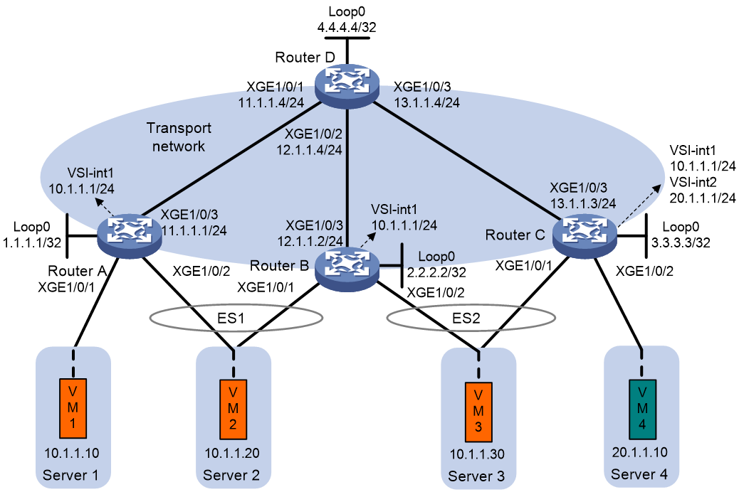
Procedure
1. On VM 1, VM 2, and VM 3, specify 10.1.1.1 as the gateway address. On VM 4, specify 20.1.1.1 as the gateway address. (Details not shown.)
2. Configure IP addresses and unicast routing settings:
# Assign IP addresses to the interfaces, as shown in Figure 17. (Details not shown.)
# Configure OSPF on all transport network routers (Routers A through D) for them to reach one another. (Details not shown.)
3. Configure Router A:
# Enable L2VPN.
<RouterA> system-view
[RouterA] l2vpn enable
# Disable remote MAC address learning and remote ARP learning.
[RouterA] vxlan tunnel mac-learning disable
[RouterA] vxlan tunnel arp-learning disable
# Create an EVPN instance on VSI vpna, and configure the router to automatically generate an RD and a route target for the EVPN instance.
[RouterA] vsi vpna
[RouterA-vsi-vpna] evpn encapsulation vxlan
[RouterA-vsi-vpna-evpn-vxlan] route-distinguisher auto router-id
[RouterA-vsi-vpna-evpn-vxlan] vpn-target auto
[RouterA-vsi-vpna-evpn-vxlan] quit
# Create VXLAN 10.
[RouterA-vsi-vpna] vxlan 10
[RouterA-vsi-vpna-vxlan-10] quit
[RouterA-vsi-vpna] quit
# Configure BGP to advertise BGP EVPN routes.
[RouterA] bgp 200
[RouterA-bgp-default] peer 4.4.4.4 as-number 200
[RouterA-bgp-default] peer 4.4.4.4 connect-interface loopback 0
[RouterA-bgp-default] address-family l2vpn evpn
[RouterA-bgp-default-evpn] peer 4.4.4.4 enable
[RouterA-bgp-default-evpn] quit
[RouterA-bgp-default] quit
# Map Ten-GigabitEthernet 0/0/6 to VSI vpna.
[RouterA] interface ten-gigabitethernet 0/0/6
[RouterA-Ten-GigabitEthernet0/0/6] xconnect vsi vpna
[RouterA-Ten-GigabitEthernet0/0/6] quit
# Assign an ESI to Ten-GigabitEthernet 0/0/7.
[RouterA] interface ten-gigabitethernet 0/0/7
[RouterA-Ten-GigabitEthernet0/0/7] esi 0.0.0.0.1
# Map Ten-GigabitEthernet 0/0/7 to VSI vpna.
[RouterA-Ten-GigabitEthernet0/0/7] xconnect vsi vpna
[RouterA-Ten-GigabitEthernet0/0/7] quit
# Configure RD and route target settings for VPN instance l3vpna.
[RouterA] ip vpn-instance l3vpna
[RouterA-vpn-instance-l3vpna] route-distinguisher 1:1
[RouterA-vpn-instance-l3vpna] address-family ipv4
[RouterA-vpn-ipv4-l3vpna] vpn-target 2:2
[RouterA-vpn-ipv4-l3vpna] quit
[RouterA-vpn-instance-l3vpna] address-family evpn
[RouterA-vpn-evpn-l3vpna] vpn-target 1:1
[RouterA-vpn-evpn-l3vpna] quit
[RouterA-vpn-instance-l3vpna] quit
# Configure VSI-interface 1.
[RouterA] interface vsi-interface 1
[RouterA-Vsi-interface1] ip binding vpn-instance l3vpna
[RouterA-Vsi-interface1] ip address 10.1.1.1 255.255.255.0
[RouterA-Vsi-interface1] mac-address 1-1-1
[RouterA-Vsi-interface1] distributed-gateway local
[RouterA-Vsi-interface1] local-proxy-arp enable
[RouterA-Vsi-interface1] quit
# Associate VSI-interface 3 with VPN instance l3vpna, and configure the L3 VXLAN ID as 1000 for the VPN instance.
[RouterA] interface vsi-interface 3
[RouterA-Vsi-interface3] ip binding vpn-instance l3vpna
[RouterA-Vsi-interface3] l3-vni 1000
[RouterA-Vsi-interface3] quit
# Specify VSI-interface 1 as the gateway interface for VSI vpna.
[RouterA] vsi vpna
[RouterA-vsi-vpna] gateway vsi-interface 1
[RouterA-vsi-vpna] quit
4. Configure Router B:
# Enable L2VPN.
<RouterB> system-view
[RouterB] l2vpn enable
# Disable remote MAC address learning and remote ARP learning.
[RouterB] vxlan tunnel mac-learning disable
[RouterB] vxlan tunnel arp-learning disable
# Create an EVPN instance on VSI vpna, and configure the router to automatically generate an RD and a route target for the EVPN instance.
[RouterB] vsi vpna
[RouterB-vsi-vpna] evpn encapsulation vxlan
[RouterB-vsi-vpna-evpn-vxlan] route-distinguisher auto router-id
[RouterB-vsi-vpna-evpn-vxlan] vpn-target auto
[RouterB-vsi-vpna-evpn-vxlan] quit
# Create VXLAN 10.
[RouterB-vsi-vpna] vxlan 10
[RouterB-vsi-vpna-vxlan-10] quit
[RouterB-vsi-vpna] quit
# Configure BGP to advertise BGP EVPN routes.
[RouterB] bgp 200
[RouterB-bgp-default] peer 4.4.4.4 as-number 200
[RouterB-bgp-default] peer 4.4.4.4 connect-interface loopback 0
[RouterB-bgp-default] address-family l2vpn evpn
[RouterB-bgp-default-evpn] peer 4.4.4.4 enable
[RouterB-bgp-default-evpn] quit
[RouterB-bgp-default] quit
# Assign an ESI to Ten-GigabitEthernet 0/0/6.
[RouterB] interface ten-gigabitethernet 0/0/6
[RouterB-Ten-GigabitEthernet0/0/6] esi 0.0.0.0.1
# Map Ten-GigabitEthernet 0/0/6 to VSI vpna.
[RouterB-Ten-GigabitEthernet0/0/6] xconnect vsi vpna
[RouterB-Ten-GigabitEthernet0/0/6] quit
# Assign an ESI to Ten-GigabitEthernet 0/0/7.
[RouterB] interface ten-gigabitethernet 0/0/7
[RouterB-Ten-GigabitEthernet0/0/7] esi 0.0.0.0.2
# Map Ten-GigabitEthernet 0/0/7 to VSI vpna.
[RouterB-Ten-GigabitEthernet0/0/7] xconnect vsi vpna
[RouterB-Ten-GigabitEthernet0/0/7] quit
# Configure RD and route target settings for VPN instance l3vpna.
[RouterB] ip vpn-instance l3vpna
[RouterB-vpn-instance-l3vpna] route-distinguisher 2:2
[RouterB-vpn-instance-l3vpna] address-family ipv4
[RouterB-vpn-ipv4-l3vpna] vpn-target 2:2
[RouterB-vpn-ipv4-l3vpna] quit
[RouterB-vpn-instance-l3vpna] address-family evpn
[RouterB-vpn-evpn-l3vpna] vpn-target 1:1
[RouterB-vpn-evpn-l3vpna] quit
[RouterB-vpn-instance-l3vpna] quit
# Configure VSI-interface 1.
[RouterB] interface vsi-interface 1
[RouterB-Vsi-interface1] ip binding vpn-instance l3vpna
[RouterB-Vsi-interface1] ip address 10.1.1.1 255.255.255.0
[RouterB-Vsi-interface1] mac-address 1-1-1
[RouterB-Vsi-interface1] distributed-gateway local
[RouterB-Vsi-interface1] local-proxy-arp enable
[RouterB-Vsi-interface1] quit
# Associate VSI-interface 3 with VPN instance l3vpna, and configure the L3 VXLAN ID as 1000 for the VPN instance.
[RouterB] interface vsi-interface 3
[RouterB-Vsi-interface3] ip binding vpn-instance l3vpna
[RouterB-Vsi-interface3] l3-vni 1000
[RouterB-Vsi-interface3] quit
# Specify VSI-interface 1 as the gateway interface for VSI vpna.
[RouterB] vsi vpna
[RouterB-vsi-vpna] gateway vsi-interface 1
[RouterB-vsi-vpna] quit
5. Configure Router C:
# Enable L2VPN.
<RouterC> system-view
[RouterC] l2vpn enable
# Disable remote MAC address learning and remote ARP learning.
[RouterC] vxlan tunnel mac-learning disable
[RouterC] vxlan tunnel arp-learning disable
# Create an EVPN instance on VSI vpna, and configure the router to automatically generate an RD and a route target for the EVPN instance.
[RouterC] vsi vpna
[RouterC-vsi-vpna] evpn encapsulation vxlan
[RouterC-vsi-vpna-evpn-vxlan] route-distinguisher auto router-id
[RouterC-vsi-vpna-evpn-vxlan] vpn-target auto
[RouterC-vsi-vpna-evpn-vxlan] quit
# Create VXLAN 10.
[RouterC-vsi-vpna] vxlan 10
[RouterC-vsi-vpna-vxlan-10] quit
[RouterC-vsi-vpna] quit
# Create an EVPN instance on VSI vpnb, and configure the router to automatically generate an RD and a route target for the EVPN instance.
[RouterC] vsi vpnb
[RouterC-vsi-vpnb] evpn encapsulation vxlan
[RouterC-vsi-vpnb-evpn-vxlan] route-distinguisher auto router-id
[RouterC-vsi-vpnb-evpn-vxlan] vpn-target auto
[RouterC-vsi-vpnb-evpn-vxlan] quit
# Create VXLAN 20.
[RouterC-vsi-vpnb] vxlan 20
[RouterC-vsi-vpnb-vxlan-20] quit
[RouterC-vsi-vpnb] quit
# Configure BGP to advertise BGP EVPN routes.
[RouterC] bgp 200
[RouterC-bgp-default] peer 4.4.4.4 as-number 200
[RouterC-bgp-default] peer 4.4.4.4 connect-interface loopback 0
[RouterC-bgp-default] address-family l2vpn evpn
[RouterC-bgp-default-evpn] peer 4.4.4.4 enable
[RouterC-bgp-default-evpn] quit
[RouterC-bgp-default] quit
# Assign an ESI to Ten-GigabitEthernet 0/0/6.
[RouterC] interface ten-gigabitethernet 0/0/6
[RouterC-Ten-GigabitEthernet0/0/6] esi 0.0.0.0.2
# Map Ten-GigabitEthernet 0/0/6 to VSI vpna.
[RouterC-Ten-GigabitEthernet0/0/6] xconnect vsi vpna
[RouterC-Ten-GigabitEthernet0/0/6] quit
# Map Ten-GigabitEthernet 0/0/7 to VSI vpnb.
[RouterC] interface ten-gigabitethernet 0/0/7
[RouterC-Ten-GigabitEthernet0/0/7] xconnect vsi vpnb
[RouterC-Ten-GigabitEthernet0/0/7] quit
# Configure RD and route target settings for VPN instance l3vpna.
[RouterC] ip vpn-instance l3vpna
[RouterC-vpn-instance-l3vpna] route-distinguisher 3:3
[RouterC-vpn-instance-l3vpna] address-family ipv4
[RouterC-vpn-ipv4-l3vpna] vpn-target 2:2
[RouterC-vpn-ipv4-l3vpna] quit
[RouterC-vpn-instance-l3vpna] address-family evpn
[RouterC-vpn-evpn-l3vpna] vpn-target 1:1
[RouterC-vpn-evpn-l3vpna] quit
[RouterC-vpn-instance-l3vpna] quit
# Configure VSI-interface 1.
[RouterC] interface vsi-interface 1
[RouterC-Vsi-interface1] ip binding vpn-instance l3vpna
[RouterC-Vsi-interface1] ip address 10.1.1.1 255.255.255.0
[RouterC-Vsi-interface1] mac-address 1-1-1
[RouterC-Vsi-interface1] distributed-gateway local
[RouterC-Vsi-interface1] local-proxy-arp enable
[RouterC-Vsi-interface1] quit
# Configure VSI-interface 2.
[RouterC] interface vsi-interface 2
[RouterC-Vsi-interface2] ip binding vpn-instance l3vpna
[RouterC-Vsi-interface2] ip address 20.1.1.1 255.255.255.0
[RouterC-Vsi-interface2] mac-address 2-2-2
[RouterC-Vsi-interface2] distributed-gateway local
[RouterC-Vsi-interface2] local-proxy-arp enable
[RouterC-Vsi-interface2] quit
# Associate VSI-interface 3 with VPN instance l3vpna, and configure the L3 VXLAN ID as 1000 for the VPN instance.
[RouterC] interface vsi-interface 3
[RouterC-Vsi-interface3] ip binding vpn-instance l3vpna
[RouterC-Vsi-interface3] l3-vni 1000
[RouterC-Vsi-interface3] quit
# Specify VSI-interface 1 as the gateway interface for VSI vpna.
[RouterC] vsi vpna
[RouterC-vsi-vpna] gateway vsi-interface 1
[RouterC-vsi-vpna] quit
# Specify VSI-interface 2 as the gateway interface for VSI vpnb.
[RouterC] vsi vpnb
[RouterC-vsi-vpnb] gateway vsi-interface 2
[RouterC-vsi-vpnb] quit
6. Configure Router D:
# Establish BGP connections with other transport network routers.
<RouterD> system-view
[RouterD] bgp 200
[RouterD-bgp-default] group evpn
[RouterD-bgp-default] peer 1.1.1.1 group evpn
[RouterD-bgp-default] peer 2.2.2.2 group evpn
[RouterD-bgp-default] peer 3.3.3.3 group evpn
[RouterD-bgp-default] peer evpn as-number 200
[RouterD-bgp-default] peer evpn connect-interface loopback 0
# Configure BGP to advertise BGP EVPN routes, and disable route target filtering for BGP EVPN routes.
[RouterD-bgp-default] address-family l2vpn evpn
[RouterD-bgp-default-evpn] peer evpn enable
[RouterD-bgp-default-evpn] undo policy vpn-target
# Configure Router D as an RR.
[RouterD-bgp-default-evpn] peer evpn reflect-client
[RouterD-bgp-default-evpn] quit
[RouterD-bgp-default] quit
Verifying the configuration
1. Verify the EVPN VXLAN multihoming configuration on Router C. (Details not shown.)
# Verify that Router C has advertised and received the following BGP EVPN routes:
¡ IP prefix advertisement routes for the gateways.
¡ IMET routes for VSIs.
¡ MAC/IP advertisement routes.
¡ Ethernet auto-discovery routes and Ethernet segment routes.
# Verify that Router C has ECMP routes to VM 2.
<RouterC> display evpn routing-table vpn-instance l3vpna
VPN instance:l3vpna Local L3VNI:1000
IP address Nexthop Outgoing interface NibID
10.1.1.10 1.1.1.1 Vsi-interface3 0x18000001
10.1.1.20 2.2.2.2 Vsi-interface3 0x18000000
1.1.1.1 Vsi-interface3 0x18000001
# Verify that Router C has equal-cost L2VPN MAC address entries and EVPN MAC address entries for VM 2.
<RouterC> display l2vpn mac-address
MAC Address State VSI Name Link ID/Name Aging
0001-0001-0010 EVPN vpna Tunnel0 NotAging
0001-0001-0020 EVPN vpna Tunnel0 NotAging
Tunnel1 NotAging
0001-0001-0030 Dynamic vpna 0x0 NotAging
0002-0001-0010 Dynamic vpnb 0x0 NotAging
<RouterC> display evpn route mac
Flags: D - Dynamic B - BGP L - Local active
G - Gateway S - Static M - Mapping I - Invalid
E – Multihoming ES sync F - Leaf
VSI name: vpna
EVPN instance: -
MAC address Link ID/Name Flags Encap Next hop
0001-0001-0030 0 DL VXLAN -
0001-0001-0010 Tunnel0 B VXLAN 1.1.1.1
0001-0001-0020 Tunnel0 B VXLAN 1.1.1.1
Tunnel1 B VXLAN 2.2.2.2
VSI name: vpnb
EVPN instance: -
MAC address Link ID/Name Flags Next hop
0002-0001-0010 0 DL -
# Verify that Router C has information about local and remote ESs.
<RouterC> display evpn es local
Redundancy mode: A - All active, S - Single active
VSI name : vpna
ESI Tag ID DF address Mode State ESI label
0000.0000.0000.0000.0002 - 2.2.2.2 A Up -
<RouterC> display evpn es remote
Control Flags: P - Primary, B - Backup, C - Control word
VSI name : vpna
ESI : 0000.0000.0000.0000.0001
A-D per ES routes :
Peer IP Remote Redundancy mode
1.1.1.1 All-active
2.2.2.2 All-active
A-D per EVI routes :
Tag ID Peer IP
- 1.1.1.1
- 2.2.2.2
ESI : 0000.0000.0000.0000.0002
Ethernet segment routes :
2.2.2.2
A-D per ES routes :
Peer IP Remote Redundancy mode
2.2.2.2 All-active
A-D per EVI routes :
Tag ID Peer IP
- 2.2.2.2
2. Verify that the VMs can communicate with one another.