- Table of Contents
- Related Documents
-
| Title | Size | Download |
|---|---|---|
| 01-Text | 6.91 MB |
Contents
General safety recommendations
Examining the installation site
Grounding the F5030/F5030-6GW/F5060/F5080/F5000-M/F5000-A/F5030-D/F5060-D/F5080-D firewall
Grounding the F5030-6GW-G firewall
Installing the firewall in a standard 19-inch rack
Installing an MPU or an interface module
Connecting a copper Ethernet port
Accessing the firewall for the first time
Logging in from the Web interface
Logging in from the console port
Replacing an MPU or an interface module
Replacing a transceiver module
Hardware management and maintenance
Displaying detailed information about the firewall
Displaying software and hardware version information for the firewall
Displaying electrical label information for the firewall
Displaying the CPU usage of the firewall
Displaying the memory usage of the firewall
Displaying the operational status of power modules
Displaying temperature information for the firewall
Displaying the operational statistics about the firewall
Displaying transceiver module information
Configuration terminal display problem
Appendix A Chassis and FRU views and technical specifications
F5030/F5030-6GW/F5060/F5080/F5000-M/F5000-A
Network data encryption modules
Network data encryption module specifications
AC power module specifications
DC power module specifications
Transceiver modules for GE copper ports
F5030/F5030-6GW/F5060/F5080/F5000-M/F5000-A/F5030-D/F5060-D/F5080-D
Making an Ethernet twisted pair cable
Preparing for installation
Safety recommendations
To avoid any equipment damage or bodily injury, read the following safety recommendations before installation. Note that the recommendations do not cover every possible hazardous condition.
Safety symbols
When reading this document, note the following symbols:
![]() WARNING means an alert that calls attention to important information that if
not understood or followed can result in personal injury.
WARNING means an alert that calls attention to important information that if
not understood or followed can result in personal injury.
![]() CAUTION means an alert that calls attention to important information that if
not understood or followed can result in data loss, data corruption, or damage
to hardware or software.
CAUTION means an alert that calls attention to important information that if
not understood or followed can result in data loss, data corruption, or damage
to hardware or software.
General safety recommendations
· Do not place the firewall on an unstable case or desk. The firewall might be severely damaged in case of a fall.
· Make sure the ground is dry and flat and anti-slip measures are in place.
· Keep the chassis and installation tools away from walk areas.
· Keep the chassis clean and dust-free.
· Do not place the firewall near water or in a damp environment. Prevent water or moisture from entering the firewall chassis.
· Ensure good ventilation of the equipment room and keep the air inlet and outlet vents of the firewall free of obstruction.
· Make sure the operating voltage is in the required range.
· Use a screwdriver, rather than your fingers, to fasten screws.
· Stack devices according to the sizes of and packing symbols on the packages.
Packing symbols
|
Symbol |
Description |
|
|
Stored with a maximum stack of n units. |
|
|
Transported and stored with the arrows up. |
|
|
Transported and stored with care. |
|
|
Transported and stored avoiding humidity, rains and wet floor. |


Electrical safety
· Carefully examine your work area for possible hazards such as moist floors, ungrounded power extension cables, and missing safety grounds.
· Locate the emergency power-off switch in the room before installation. Shut the power off at once in case accident occurs.
· Do not work alone when the firewall has power.
· Always verify that the power has been disconnected.
Laser safety
|
|
WARNING! Disconnected optical fibers or transceiver modules might emit invisible laser light. Do not stare into beams or view directly with optical instruments when the switch is operating. |
The firewall is a Class 1 laser device.
· Before you disconnect the fiber connector, execute the shutdown command in interface view to disable the optical source.
· Install dust caps to disconnected optical fiber connectors and ports on disconnected transceiver modules to avoid damage caused by built-up dust.
· Insert a dust plug into empty fiber ports.
Handling safety
When you move the firewall, follow these guidelines:
· Move and unpack the firewall carefully to avoid firewall damage.
· Unpack the firewall at least half an hour and power on the firewall at least two hours after you move it from a place below 0°C (32°F) to the equipment room. This prevents condensation and even damage to the firewall.
· Use a safety hand truck when you move multiple firewalls.
· Before you move the firewall, remove all cables from it.
· For long-distance transportation, remove all the field-replaceable units (FRUs), such as power modules and interface modules, and package them separately, and install the filler panels supplied with the firewall. For short-distance transportation, make sure all the FRUs are securely seated in the slots and the screws are fastened.
· When you move or lift the firewall chassis, support the bottom of the chassis, rather than holding any FRU.
· Make sure the accessories of the firewall are not lost or damaged during firewall moving.
Examining the installation site
The firewall can only be used indoors. To make sure the firewall operates correctly and to prolong its service lifetime, the installation site must meet the following requirements.
Weight support
Make sure the floor can support the total weight of the rack, chassis, modules, and all other components. For more information, see "Dimensions and weights."
Temperature and humidity
Maintain appropriate temperature and humidity in the equipment room.
· Lasting high relative humidity can cause poor insulation, electricity leakage, mechanical property change of materials, and metal corrosion.
· Lasting low relative humidity can cause washer contraction and ESD and bring problems including loose captive screws and circuit failure.
· High temperature can accelerate the aging of insulation materials and significantly lower the reliability and lifespan of the firewall.
For the temperature and humidity requirements of the firewall, see 0.
Temperature/humidity requirements
|
Temperature |
Relative humidity |
|
· Operating: ¡ Without drives: 0°C to 45°C (32°F to 113°F) ¡ With drives: 5°C to 40°C (41°F to 104°F) · Storage: –40°C to +70°C (–40°F to +158°F) |
· Operating: 5% RH to 95% RH, noncondensing · Storage: 5% RH to 95% RH, noncondensing |
Cleanliness
Dust buildup on the chassis might result in electrostatic adsorption, which causes poor contact of metal components and contact points, especially when indoor relative humidity is low. In the worst case, electrostatic adsorption can cause communication failure.
Dust concentration limit in the equipment room
|
Substance |
Concentration limit (particles/m3) |
|
Dust particles |
≤ 3 × 10⁴ (No visible dust on desk in three days) |
|
NOTE: Dust particle diameter ≥ 5 µm |
|
The equipment room must also meet strict limits on salts, acids, and sulfides to eliminate corrosion and premature aging of components, as shown in 0.
Harmful gas limits in an equipment room
|
Gas |
Max. (mg/m3) |
|
SO2 |
0.2 |
|
H2S |
0.006 |
|
NH3 |
0.05 |
|
Cl2 |
0.01 |
|
NO2 |
0.04 |
Cooling system
The firewall uses a front-rear air aisle. For adequate heat dissipation, follow these guidelines:
· Select a fan tray model that provides an airflow direction matching the heat dissipation requirements at the installation site for the firewall.
· Reserve a minimum clearance of 100 mm (3.94 in) around the inlet and outlet air vents.
· Make sure the installation site has a good cooling system.
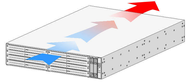
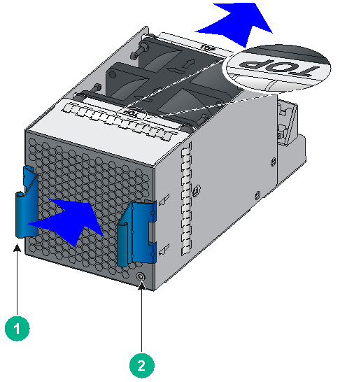
The FAN-20F-2-A and LSWM1BFANSC fan trays blow air from the power module side to the port side as shown in 0. The fan trays have a blue handle.
Airflow with the FAN-20F-2-A/LSWM1BFANSC fan trays installed
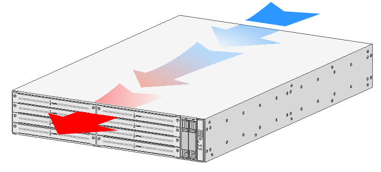
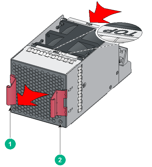
The FAN-20B-2-A and LSWM1BFANSCB fan trays draw air from the port side to the power module side as shown in 0. The fan trays have a red handle.
Airflow with the FAN-20B-2-A/LSWM1BFANSCB fan trays installed
ESD prevention
To prevent electrostatic discharge (ESD), note the following guidelines:
· Make sure the firewall and the rack are reliably grounded.
· Take dust-proof measures for the equipment room. For more information, see "Cleanliness."
· Maintain the humidity and temperature at an acceptable level. For more information, see "Temperature and humidity."
· Put the removed interface modules away on an ESD workbench, with the PCB upward, or put them in ESD bags for future use.
· Always wear ESD clothing, ESD gloves, and an ESD wrist strap when you install or remove a transceiver module.
EMI
All electromagnetic interference (EMI) sources, from outside or inside of the firewall and application system, adversely affect the firewall in the following ways:
· A conduction pattern of capacitance coupling.
· Inductance coupling.
· Electromagnetic wave radiation.
· Common impedance (including the grounding system) coupling.
To prevent EMI, use the following guidelines:
· If AC power is used, use a single-phase three-wire power receptacle with protection earth (PE) to filter interference from the power grid.
· Keep the firewall far away from radio transmitting stations, radar stations, and high-frequency devices.
· Use electromagnetic shielding, for example, shielded interface cables, when necessary.
· To prevent signal ports from getting damaged by overvoltage or overcurrent caused by lightning strikes, route interface cables only indoors. If part of the network cable of an Ethernet port must be routed outdoors, connect a lightning arrester to the cable before you plug the cable into the port.
Lightning protection
To protect the firewall from lightning better, do as follows:
· Make sure the grounding cable of the chassis is reliably grounded.
· Make sure the grounding terminal of the AC power receptacle is reliably grounded.
· If an AC power cord is routed from outdoors for connecting to the device, connect the power cord first to a power lightning arrester before connecting it to the power receptacle on the device.
· If a network cable is routed from outdoors for connecting to an Ethernet port on the firewall, connect the network cable first to a network port lightning arrester before connecting it to the port.
|
|
IMPORTANT: No network port lightning arrester or AC power lightning arrester is provided with the device. Prepare them as required. For the technical specifications and installation instructions for the lightning protectors, see the documents shipped with them. |
Power supply
Verify that the power system at the installation site meets the requirements of the power modules, including the input method and rated input voltage. For more information, see "Appendix A Chassis views and technical specifications."
Installation tools
No installation tools are provided with the firewall. Prepare installation tools yourself as required.
Installation tools
|
|
|
|
|
|
Flathead screwdriver |
Phillips screwdriver |
Needle-nose pliers |
Marker |
|
|
|
|
|
|
Diagonal pliers |
ESD wrist strap |
Wire-stripping pliers |
Crimping tool |
Installation accessories
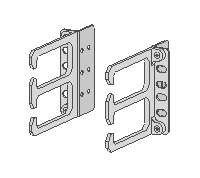
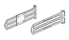
Installation accessories
|
|
|
|
|
|
Mounting brackets with cable management brackets attached |
Slide rails and chassis rails |
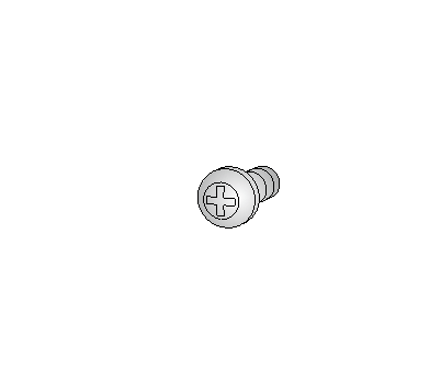
M4 screw |
M6 screw |
|
|
|
|
|
|
Cage nut |
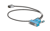
Console cable |
Grounding cable |
|

Pre-installation checklist
Checklist before installation
|
Item |
Requirements |
|
|
Installation site |
Ventilation |
· There is a minimum clearance of 100 mm (3.94 in) around the inlet and outlet air vents for heat dissipation of the firewall chassis. · A ventilation system is available at the installation site. |
|
Temperature |
· Operating: ¡ Without drives: 0°C to 45°C (32°F to 113°F) ¡ With drives: 5°C to 40°C (41°F to 104°F) · Storage: –40°C to +70°C (–40°F to +158°F) |
|
|
Relative humidity |
· Operating: 5% RH to 95% RH, noncondensing · Storage: 5% RH to 95% RH, noncondensing |
|
|
Cleanness |
· Dust concentration ≤ 3 × 10⁴ particles/m3 · No dust on desk within three days |
|
|
ESD prevention |
· The firewall and the rack are reliably grounded. · The equipment room is dust-proof. · The humidity and temperature are at an acceptable level. · Always wear ESD clothing, ESD gloves, and an ESD wrist strap and when you install and remove a transceiver module. · Put the removed interface modules on an ESD workbench, with the PCB upward, or put them in ESD bags for future use. |
|
|
EMI prevention |
· Take effective measures to protect the power system from the power grid system. · Separate the protection ground of the firewall from the grounding device or lightning protection grounding device as far as possible. · Keep the firewall far away from radio stations, radar and high-frequency devices working in high current. · Use electromagnetic shielding when necessary. |
|
|
Lightning protection |
· The grounding cable of the chassis is reliably grounded. · The grounding terminal of the AC power receptacle is reliably grounded. · (Optional) A power lightning arrester is installed. |
|
|
Power supply |
Verify that the power system at the installation site meets the requirements of the power modules, including the input method and rated input voltage. |
|
|
Tools and accessories |
· Installation accessories supplied with the firewall · User supplied tools |
|
|
Reference |
· Documents shipped with the firewall · Online documents |
|
Installing the firewall
|
|
WARNING! Keep the tamper-proof seal on a mounting screw on the chassis cover intact, and if you want to open the chassis, contact the local agent of H3C for permission. Otherwise, H3C shall not be liable for any consequence caused thereby. |
The installation method is similar for the F5030, F5030-6GW, F5030-6GW-G, F5060, F5080, F5030-D, F5060-D, F5080-D, F5000-M, and F5000-A firewalls. This section uses an F5080 firewall as an example. The firewall view varies by model. The following figures are for illustration only.
Installation flow
Installation flow for the firewall
|
Step |
Description |
|
Before installation, make sure all requirements on the checklist are met and the firewall is powered off. |
|
|
Before installation, make sure the firewall and rack are reliably grounded and you wear an ESD wrist strap. |
|
|
The firewall is heavy. Both mounting brackets and slide rails are required to support the weight of the chassis. |
|
|
Before you install a power module, make sure the power module is not connected to any power source and the grounding cable of the firewall is connected reliably. |
|
|
Install compatible fan trays on the firewall. |
|
|
No MPU or interface module is provided with the firewall. Purchase them as required. |
|
|
Install compatible drives on the firewall. |
|
|
The firewall provides various ports. Choose compatible transceiver modules and cables as required. To avoid bodily injury or device damage, read the restrictions and guidelines carefully before connection. |
|
|
Connect compatible power cords to the power modules. |
|
|
Verify that the firewall is installed securely and reliably grounded, and that the power modules are as required. |
Grounding the firewall
|
|
WARNING! · Correctly connecting the firewall grounding cable is crucial to lightning protection and EMI protection. Before installing or using the firewall, connect the grounding cable to it correctly. · Do not connect the firewall grounding cable to a fire main or lightning rod. |
Grounding the F5030/F5030-6GW/F5060/F5080/F5000-M/F5000-A/F5030-D/F5060-D/F5080-D firewall
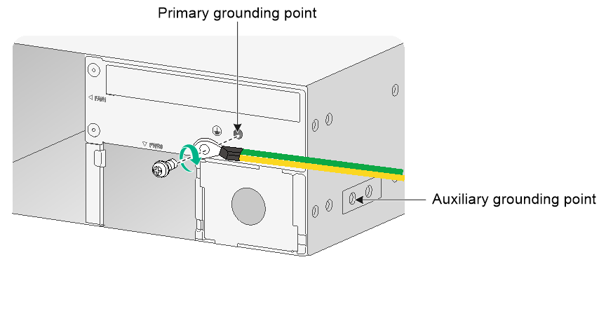
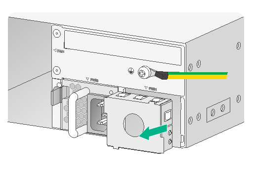
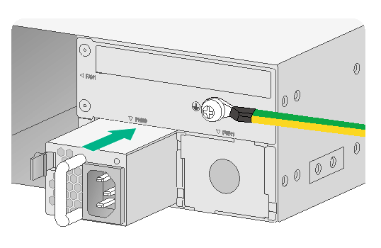
As shown in 0, the firewall provides a primary grounding point at the rear panel and an auxiliary grounding point at the left side. The primary grounding point has a grounding sign and a grounding screw.
The grounding screw at the primary grounding point is also applicable to the auxiliary grounding point. To use the auxiliary grounding point, attach the grounding cable to the grounding point before you install the firewall in a rack.
The procedure is the same for connecting a grounding cable to the primary grounding point and the auxiliary grounding point. This section uses the primary grounding point as an example.
To connect the grounding cable:
Remove the grounding screw from the primary grounding point at the device rear.
Attach the grounding screw to the ring terminal of the grounding cable.
Use a screwdriver to fasten the grounding screw into the grounding hole.
Connect the other end of the grounding cable to the grounding strip on the rack.
Grounding the firewall by using the primary grounding point
Grounding the F5030-6GW-G firewall
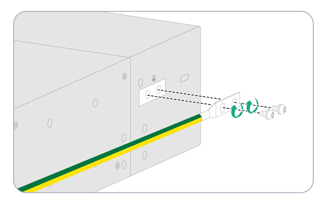
The F5030-6GW-G firewall provides primary and auxiliary grounding points on the side panel. The primary grounding point is close to the firewall front panel and has a grounding sign.
|
|
IMPORTANT: Before mounting the F5030-6GW-G firewall in a rack, connect the grounding cable for it. Use the grounding point near the front panel. If you use the ground point near the rear panel, you cannot attach the chassis rails to the firewall. |
To connect the grounding cable to the firewall:
Use the grounding screws to attach the two-hole terminal of the grounding cable to the grounding holes and fasten the screws.
Connect the other end of the grounding cable to a grounding strip.
Connecting the grounding cable to the F5030-6GW-G firewall (primary grounding point)
Installing the firewall in a standard 19-inch rack
|
|
WARNING! To avoid bodily injury and device damage, at least two persons are required to install the firewall. |
|
CAUTION: · Ensure a clearance of 1 RU (44.45 mm, or 1.75 in) between the firewall and walls or other devices for heat dissipation. · The mounting brackets and chassis rails are required to support the weight of the chassis. |
To mount the firewall in a rack, make sure the rack meets the requirements described in 0.
Firewall dimensions and rack requirements
|
Firewall dimensions |
Rack requirements |
|
· Height—88.1 mm (3.47 in) · Width—440 mm (17.32 in) · Total depth—775.5 mm (30.53 in) ¡ 660 mm (25.98 in) for the chassis ¡ 90 mm (3.54 in) for the cable management bracket at the chassis front ¡ 25.5 mm (1.00 in) for the power module handle at the chassis rear |
· A minimum of 1 m (3.28 ft) in depth (recommended). · A minimum of 100 mm (3.94 in) between the front rack posts and the front door. · A minimum of 760 mm (29.92 in) between the front rack posts to the rear door. · 518 mm (20.39 in) to 923 mm (36.34 in) from the front rack posts to the rear rack posts. |
To install the firewall in a 19-inch rack:
Make sure the rack is sturdy and reliably grounded.
Wear an ESD wrist strap and unpack the firewall and accessories.
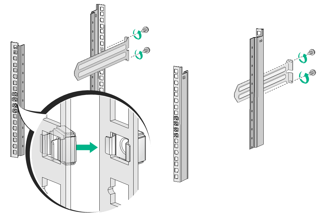
Use a mounting bracket and a slide rail to mark the cage nut installation positions on the front and rear rack posts, respectively. Four cage nuts are required on each front rack post and two are required on each rear rack post.
Install cages nuts at the marked positions.
Use M6 screws to attach two slide rails to the rear rack posts.
Installing cage nuts and slide rails
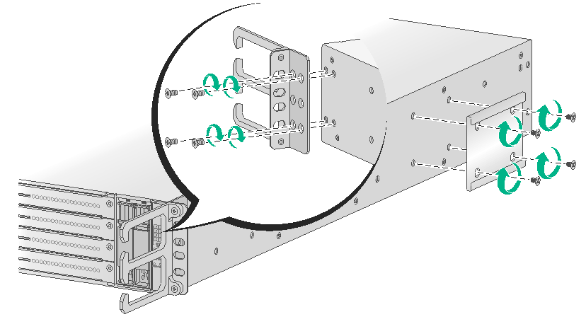
Use the provided M4 screws to attach the mounting brackets and chassis rails to both sides of the firewall.
The firewall provides multiple installation positions for chassis rails. Install chassis rails to the appropriate positions and make sure the front ends of the slide rails can reach out of the chassis rails after the firewall is installed in the rack.
Attaching the mounting brackets and chassis rails to the firewall
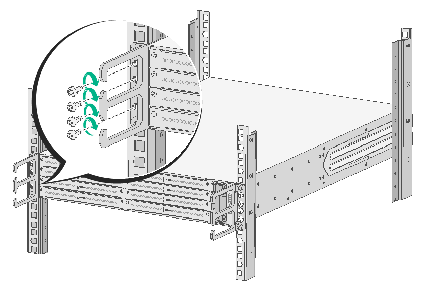
One person supports the bottom of the firewall, align the chassis rails with the slide rails, and slide the slide rails into the chassis rails until the mounting brackets are flush with the front rack posts.
Fasten the M6 rack screws with a Phillips screwdriver to secure the mounting brackets to the front rack posts.
Mounting the firewall to the rack
Installing a power module
|
|
CAUTION: · Make sure the power module is powered off and the device is correctly grounded before installation. · Install a filler panel over an empty power module slot to prevent dust and ensure good ventilation in the chassis. · Do not install both AC and DC power modules on the same device. |
No power module is provided with the firewall. Purchase power modules as required. The installation procedures for AC and DC power modules are similar. The following procedure installs an AC power module.
To install a power module:
To install the power module to slot PWR1, remove the filler panel from the slot. To install the power module to slot PWR2, skip this step.
Removing the filler panel
Install the power module in a correct direction (with the power receptacle at right):
Grasp the handle of the module with one hand and support the module bottom with the other.
Push the power module along the guide rails into the slot until it has firm contact with the slot.
Installing an AC power module
Installing a fan tray
|
|
CAUTION: · Before installation, make sure the airflow direction provided by the fan tray meets the requirements for installation ventilation. · The device comes with both fan tray slots empty. To ensure good ventilation, you must install two fan trays of the same model before powering on the device. · If one fan tray fails during the device operation, replace the fan tray immediately and keep the fan tray in the slot before the replacement. If both fan trays fail, replace one fan tray first immediately. Replace the other fan tray after the new fan tray operates correctly. Do not remove both fan trays at the same time. This operation can cause the device to power off. · To prevent damage to the fan tray and the connectors on the backplane, insert the fan tray gently. If you encounter any resistance while inserting the fan tray, pull out the fan tray, re-orient it, and then insert it again. |
|
|
IMPORTANT: Only the F5030-6GW-G firewall supports the LSWM1BFANSC and LSWM1BFANSCB fan trays. |
The firewall supports hot swapping of fan trays.
No fan tray is provided with the firewall. Purchase fan trays as required.
The installation procedures for the FAN-20B-2-A, LSWM1BFANSC, LSWM1BFANSCB and the FAN-20F-2-A fan trays are similar. The following procedure installs a FAN-20B-2-A fan tray.
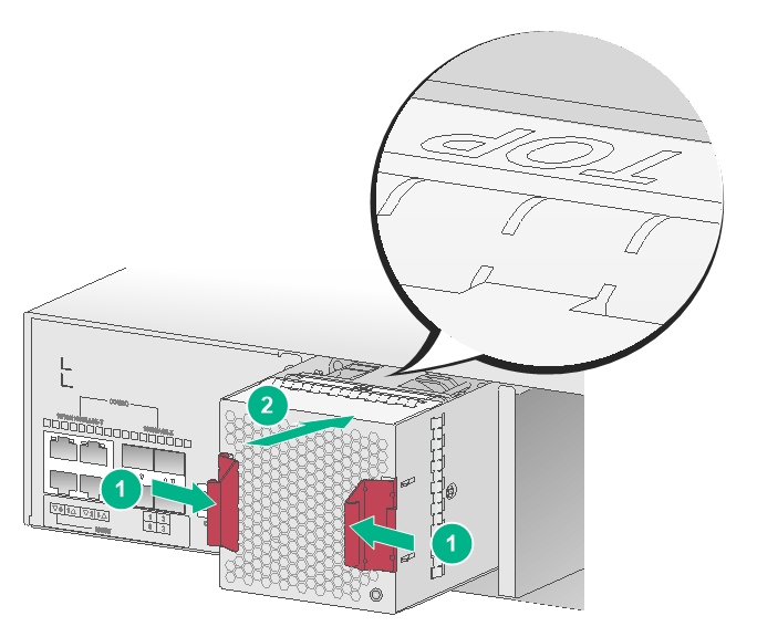
To install a fan tray:
1. Wear an ESD wrist strap and make sure it makes good skin contact and is reliably grounded.
Orient the fan tray with the "TOP" mark on the top, grasp the fan tray handle with one hand, and support its bottom with the other hand. Slide the fan tray along the guide rails into the slot until it has a firm contact with the backplane.
Installing a fan tray
Installing an MPU or an interface module
|
|
CAUTION: · Only slots 0/0 and 1/0 on the F5030-D/F5060-D/F5080-D support installation of MPUs. · If the F5030-D/F5060-D/F5080-D is installed with two MPUs, you can hot swap an MPU. If the F5030-D/F5060-D/F5080-D is installed with only one MPU, you cannot hot swap the MPU. · Do not hot swap interface modules. · To avoid module damage, do not touch the surface-mounted components on an interface module directly with your hands. · Install a filler panel over empty MPU and interface module slots to prevent dust and ensure good ventilation in the chassis. |
No MPU or interface module is provided with the firewall. Purchase them as required. The installation procedure is the same for MPUs and interface modules.
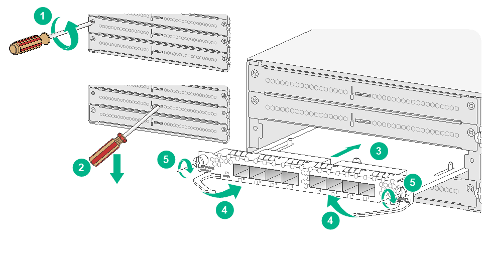
To install an interface module:
Wear an ESD wrist strap and make sure it makes good skin contact and is reliably grounded.
Remove the screws on the filler panel with a Phillips screwdriver and remove the filler panel.
Keep the filler panel for future use.
Open the ejector levers on the module and slide the module steadily into the slot along the guide rails.
Close the ejector levers until they touch the panel tightly and the module seats into the backplane.
Fasten the captive screws on the module with a Phillips screwdriver.
Installing an interface module
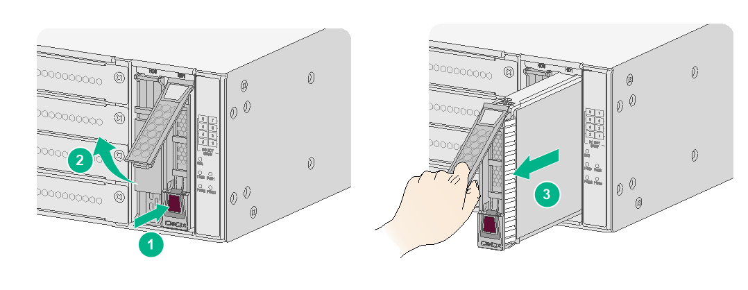
Installing a drive
|
|
CAUTION: · Do not hot swap drives. · Hold a drive by its sides. Do not touch drive components and do not squeeze, vibrate, or strike the drive. · Install a filler panel over empty drive slots to avoid damage caused by build-up dust. · Before using a drive, execute the fdisk and format commands from the CLI to partition and format the drive. |
The device does not come with any drives and cannot recognize drives from other vendors. Purchase drives from H3C as needed.
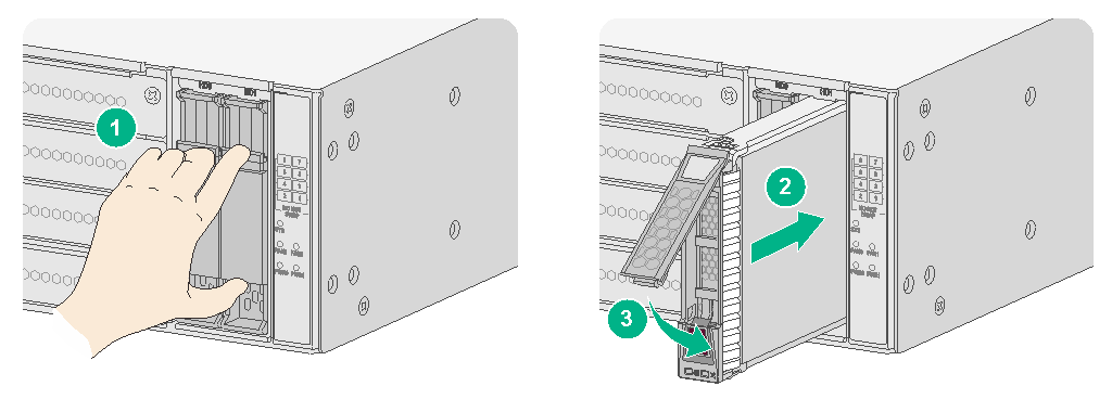
To install a drive:
Wear an ESD wrist strap and make sure it makes good skin contact and is reliably grounded.
Remove the filler panel over the drive slot.
Press the red button on the drive panel to release the locking lever.
Hold the locking lever, slide the drive into the slot along the guide rails, and then close the locking lever.
Installing the drive
Connecting Ethernet cables
Connecting a copper Ethernet port
You can use either a straight-through or a cross-over network cable to connect a copper Ethernet port. For more information about Ethernet twisted pair cables, see "Ethernet twisted pair cable."
To connect a copper Ethernet port:
Connect one end of the Ethernet cable to the copper Ethernet port of the firewall, and the other end to the Ethernet port of the peer device.
Examine whether the LEDs of the Ethernet port are normal. For more information about LEDs, see "Appendix B LEDs."
After connecting the firewall to the network, you can use the ping or tracert command to examine network connectivity. For more information, see the related command reference.
Connecting a fiber port
|
|
WARNING! Disconnected optical fibers or transceiver modules might emit invisible laser light. Do not stare into beams or view directly with optical instruments when the switch is operating. |
|
|
CAUTION: · Never bend or curve a fiber excessively. The bend radius of a fiber must be not less than 100 mm (3.94 in). · Keep the fiber end clean. · Make sure the fiber connector matches the transceiver module. · Before connecting a fiber, make sure the optical power at the receiving end does not exceed the transceiver module's upper threshold of the optical receive power. If the optical power at the receiving end exceeds the threshold, the transceiver module might be damaged. · Do not install a transceiver module connected with a fiber into a fiber port. To connect an optical fiber, first install the transceiver module in the fiber port and then connect the fiber. · Insert a dust plug into any open fiber port. · Make sure the Tx and Rx ports on a transceiver module are connected to the Rx and Tx ports on the peer end, respectively. |
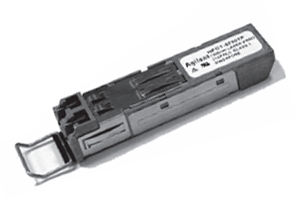
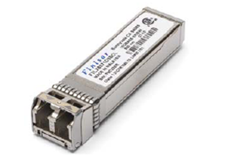
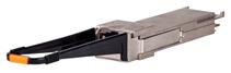
The firewall supports GE SFP transceiver modules, 10GE SFP+ transceiver modules, and 40GE QSFP+ transceiver modules. For the transceiver module specifications, see "GE fiber Ethernet port", "10 GE fiber Ethernet port" and "40 GE fiber Ethernet port."
No transceiver module is provided with the firewall. As a best practice, use H3C transceiver modules.
GE SFP transceiver module
10GE SFP+ transceiver module
40GE QSFP+ transceiver module
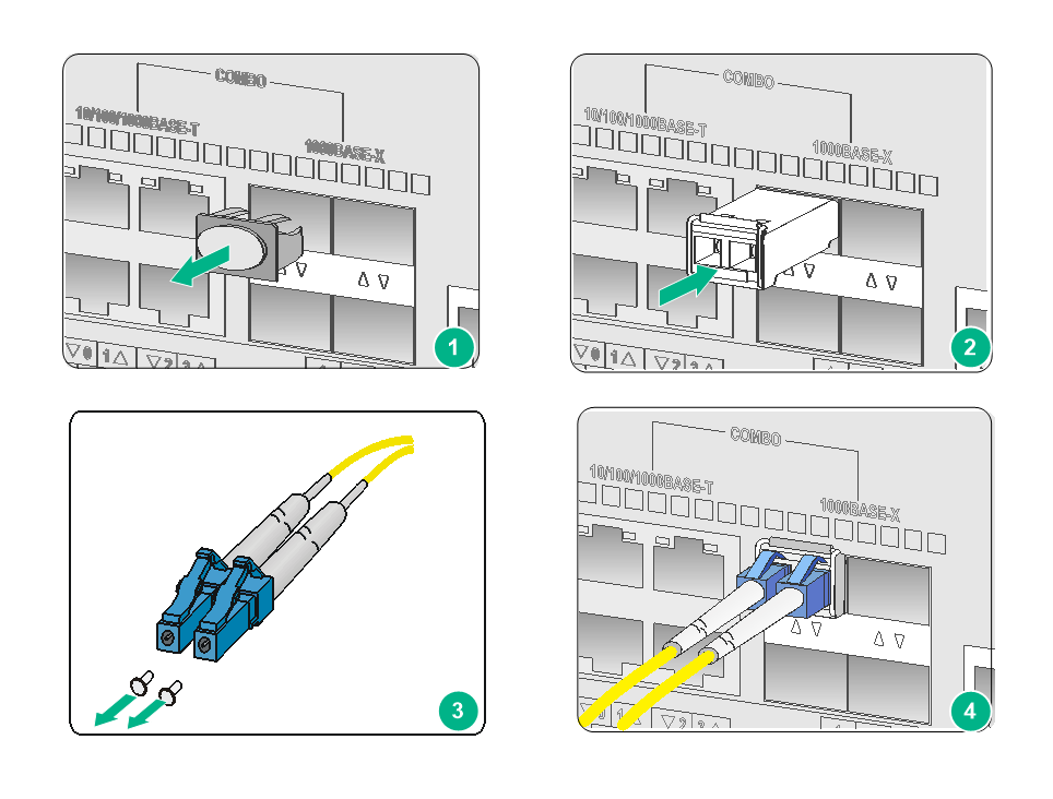
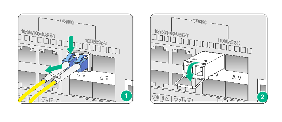
To connect a fiber port:
Remove the dust plug from the fiber port.
Install a transceiver module. Pull the bail latch on the transceiver module upwards to catch the knob on the top of the transceiver module. Take the transceiver module by its two sides and push the end without the bail latch gently into the port until it snaps into place.
Remove the dust cap from the optical fiber connector, and use dust free paper and absolute alcohol to clean the end face of the fiber connector.
Identify the Rx and Tx ports on the transceiver module. Plug one end of the optical fiber into the transceiver module in the firewall, and plug the other end into the transceiver module in the peer device.
Make sure the Rx port and the Tx port are connected to the Tx port and the Rx port on the peer device, respectively.
Connecting a fiber port
Connecting the power cord
|
|
CAUTION: Make sure the grounding cable of the firewall is correctly connected and the power source is powered off before connecting the power cord. |
Connecting an AC power cord
Connect one end of the AC power cord to the AC-input power receptacle on the power module.
Use a removable cable tie to secure the AC power cord to the power module handle.
Connect the other end of the power cord to the AC power source.

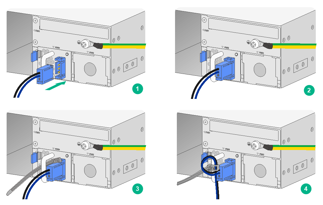
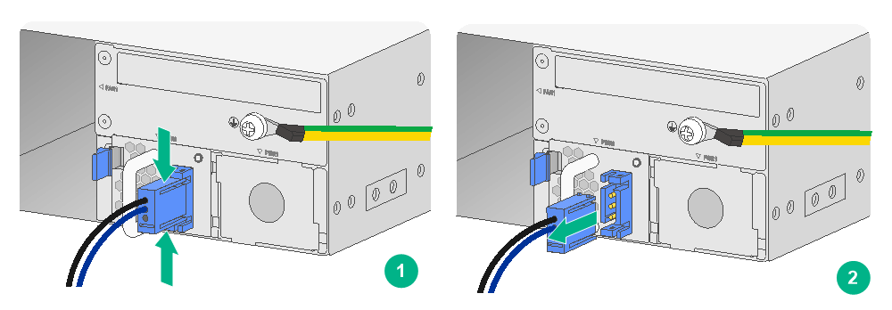
Connecting a DC power cord
Connecting a DC power cord for the F5030/F5030-6GW/F5060/F5080/F5000-M/F5000-A/F5030-D/F5060-D/F5080-D firewall
Correctly orient the DC power cord plug with the power receptacle on the power module, and insert the plug into the receptacle.
Use a removable cable tie to secure the DC power cord to the power module handle.
3. Connect the other end of the power cord to the DC power source.
Connecting a DC power cord
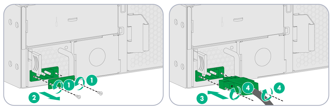
Connecting a DC power cord for the F5030-6GW-G firewall
Remove the cover over the DC power input receptacle on the DC power module.
Correctly orient the DC power cord connector, and insert the connector into the DC power input receptacle.
Fasten the screws on the DC power cord connector.
4. Connect the other end of the DC power cord to a DC power source.
Connecting the DC power cord
Verifying the installation
After installation, verify that:
· There is enough space for heat dissipation around the firewall, and the firewall is steady.
· All screws are fastened.
· The grounding cable and power cord are securely connected.
Accessing the firewall for the first time
Powering on the firewall
Checking before power-on
|
|
WARNING! Locate the emergency power-off switch in the room before power-on so you can quickly shut power off when an electrical accident occurs. |
Before powering on the firewall, verify the following information:
· The power cord and grounding cable are connected correctly.
· The correct power source is used.
· The console cable is connected correctly, the terminal or PC used for configuration has started, and the configuration parameters have been correctly set. For more information, see "Logging in from the console port."
· The interface module (if any) is installed correctly.
Powering on the firewall
Switch on the power source of the firewall.
Checking after power-on
After powering on the firewall, verify that:
· The LEDs on the front panel indicate that the device is operating correctly. For more information about LEDs, see "Appendix B LEDs."
· The fan blades are rotating and air is exhausted from the air outlet vents.
· The configuration terminal displays the following:
System is starting...
Press Ctrl+D to access BASIC-BOOTWARE MENU...
Press Ctrl+T to start heavy memory test....
Booting Normal Extended BootWare
The Extended BootWare is self-decompressing....Done.
****************************************************************************
* *
* H3C SecPath BootWare, Version 1.03 *
* *
****************************************************************************
Copyright (c) 2004-2017 New H3C Technologies Co., Ltd.
Compiled Date : Mar 28 2017
Memory Type : DDR3 SDRAM
Memory Size : 32768MB
Flash Size : 8MB
sda0 Size : 3728MB
CPLD Version : 1.0
PCB Version : Ver.B
BootWare Validating...
Press Ctrl+B to access EXTENDED-BOOTWARE MENU...
Loading the main image files...
Loading file sda0:/Main-CMW710-SYSTEM-XXXX.bin.......................
.........Done.
Loading file sda0:/Main-CMW710-BOOT-XXXX.bin..........Done.
Image file sda0:/Main-CMW710-BOOT-XXXX.bin is self-decompressing.....
Done.
System image is starting...
Cryptographic Algorithms Known-Answer Tests are running ...
CPU 0 of slot 1:
Starting Known-Answer tests in the user space.
Known-answer test for SHA1 passed.
Known-answer test for SHA224 passed.
Known-answer test for SHA256 passed.
Known-answer test for SHA384 passed.
Known-answer test for SHA512 passed.
Known-answer test for HMAC-SHA1 passed.
Known-answer test for HMAC-SHA224 passed.
Known-answer test for HMAC-SHA256 passed.
Known-answer test for HMAC-SHA384 passed.
Known-answer test for HMAC-SHA512 passed.
Known-answer test for AES passed.
Known-answer test for RSA(signature/verification) passed.
Known-answer test for RSA(encrypt/decrypt) passed.
Known-answer test for DSA(signature/verification) passed.
Known-answer test for random number generator passed.
Known-Answer tests in the user space passed.
Starting Known-Answer tests in the kernel.
Known-answer test for AES passed.
Known-answer test for HMAC-SHA1 passed.
Known-answer test for SHA1 passed.
Known-answer test for GCM passed.
Known-answer test for GMAC passed.
Known-answer test for random number generator passed.
Known-Answer tests in the kernel passed.
Starting Known-Answer tests in the engine.
Known-answer test for SHA1 passed.
Known-answer test for HMAC-SHA1 passed.
Known-answer test for AES passed.
Known-answer test for RSA(signature/verification) passed.
Known-answer test for RSA(encrypt/decrypt) passed.
Known-answer test for DSA(signature/verification) passed.
Known-answer test for random number generator passed.
Known-Answer tests in the engine passed.
Cryptographic Algorithms Known-Answer Tests passed.
Line con0 is available.
Press ENTER to get started...
…
Press ENTER to access user view of the firewall.
|
|
NOTE: To access the EXTENDED-BOOTWARE menu, press Ctrl + B within four seconds at the prompt "Press Ctrl+B to access EXTENDED-BOOTWARE MENU." If you do not press Ctrl+B at the prompt, the system starts to read and decompress program files. To enter the EXTENDED-BOOT menu afterwards, you need to reboot the device. |
Logging in to the firewall
For more information about logging in to the device, see the configuration guides and command references for the device.
Logging in from the Web interface
0 provides the default Web interface login information.
Default Web interface login information
|
Item |
Default configurations |
|
Username |
admin |
|
Password |
admin |
|
Ethernet management interface |
· F5000-A, F5000-M, F5030, F5060, F5080, F5030-6GW, F5030-6GW-G—GE1/0/0 · F5030-D, F5060-D, F5080-D—MGE1/0/0/0 |
|
IP address of the Ethernet management interface |
192.168.0.1/24 |
To log in to the firewall from the Web interface by using the default account:
Use an Ethernet cable to connect a PC to the Ethernet management interface on the firewall.
Configure an IP address in subnet 192.168.0.0/24 for the PC. Make sure the PC and the firewall are reachable to each other.
The PC must use a different IP address than the Ethernet management interface.
Start a browser, enter 192.168.0.1 in the address bar, and press Enter.
Enter the default username admin and password admin and then click Login.
Modify the login information.
At the first login from the Web interface, change the password as required in the pop-up window, and then click OK.
Keep the new password secure.
Logging in from the console port
You can use the console port to access the firewall for the first time. By default, the firewall uses the scheme access authentication mode. The username and password are both admin.
To access the firewall from the console port, use a console cable to connect the console port on the firewall to a configuration terminal, for example, a PC.
To configure and manage the firewall from the console port, you must run a terminal emulator program, TeraTermPro or PuTTY, on your configuration terminal and configure the following settings for the terminal. For more information about the terminal emulator programs, see the user guides for these programs.
· Bits per second—9,600.
· Data bits—8.
· Stop bits—1.
· Parity—None.
· Flow control—None.
Logging in through Telnet
Log in to the firewall through the console port, and enable the Telnet function in system view by using the telnet server enable command.
Enter VTY user line view, and configure the authentication mode, user role, and common properties.
By default, the authentication mode is scheme, the username is admin, and the password is admin.
Specify an IP address for the network port of the PC. Make sure the PC and the firewall are reachable to each other.
By default, the IP address of the Ethernet management interface on the firewall is 192.168.0.1/24.
Run the Telnet client on the PC and enter the login information.
Hardware replacement
|
|
CAUTION: Wear an ESD wrist strap or ESD gloves for hardware maintenance. They are not provided with the firewall. Prepare them yourself. |
Replacing a fan tray
|
|
WARNING! · To avoid bodily injury, do not touch an operating fan tray. · The fan trays are hot swappable. Follow electrical safety instructions when you hot swap a fan tray. |
|
|
CAUTION: To prevent an unbalanced fan from causing loud noise, do not touch the fan blades and rotating axis even if they are not rotating. |
To replace a fan tray:
Holding the fan tray handle with one hand and supporting the fan tray bottom with the other, pull the fan tray out of the slot along the guide rails.
Put the removed fan tray into an antistatic bag.
Install a new fan tray. For the installation procedure, see "Installing a fan tray."
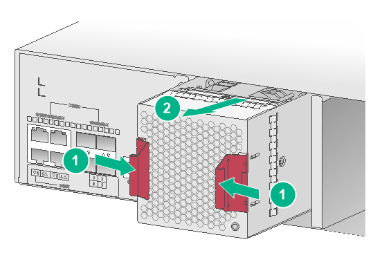
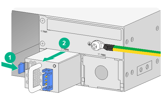
Replacing a power module
|
|
WARNING! Before removing a power module, turn off the power source and remove the power cord. |
The procedures for replacing AC and DC power modules are similar. The following procedure replaces a DC power module.
To replace a power module:
5. Turn off the power source and then remove the power cord from the power module.
To remove a DC power cord, squeeze the upper and lower sides of the plug and then pull the plug out.
Removing a DC power cord
6. Holding the handle on the power module with one hand, press the retaining latch on the power module to the right with your thumb, and pull the power module part way out of the slot.
7. Supporting the power module bottom with the other hand, slowly pull the power module out of the slot.
Put the removed power module into an antistatic bag.
Install a new power module. For the installation procedure, see "Installing a fan tray."
Removing the DC power module
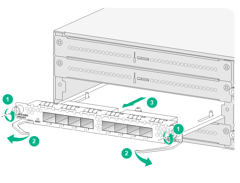
Replacing an MPU or an interface module
|
|
CAUTION: · You can hot swap an MPU only when the F5030-D/F5060-D/F5080-D has two MPUs. · Do not hot swap interface modules. |
The replacement procedure is the same for MPUs and interface modules.
To replace an interface module:
8. Power off the firewall.
9. Use a Phillips screwdriver to loosen the captive screws on the module.
10. Holding the ejector levers of the module with both hands, pull the ejector levers outward, and pull the module part way out of the slot along the guide rails.
11. Supporting the bottom of the module with one hand, use the other hand to gently pull the module out of the slot.
12. Put the removed module on an antistatic workbench or into an antistatic bag with the circuit board facing upward.
13. Install a new module. For the installation procedure, see "Installing an MPU or an interface module."
Removing an interface module
Replacing a drive
|
|
CAUTION: · To avoid storage medium damage, execute the umount command from the CLI to unmount all the file systems before removing a drive. · Do not hot swap drives. |
To replace a drive:
Log in to the Web interface. Click the Unmount button on the Storage settings page.
Wear an ESD wrist strap and make sure it makes good skin contact and is reliably grounded.
Press the red button on the drive panel to release the locking lever.
Hold the locking lever and pull the drive out of the slot.
Install a new drive. For the installation procedure, see "Installing a drive."
Removing a drive
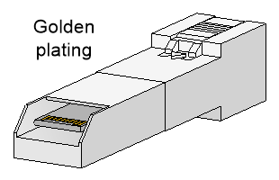
Replacing a transceiver module
|
|
WARNING! Disconnected optical fibers or transceiver modules might emit invisible laser light. Do not stare into beams or view directly with optical instruments when the switch is operating. |
When you replace a transceiver module, make sure the two transceiver modules connected by the same optical fiber are the same type. Do not touch the golden plating of the transceiver module.
Transceiver module golden plating
To replace a transceiver module:
14. Use the shutdown command in interface view at the CLI to shut down the optical source before you remove the fiber connector.
15. Remove the LC connectors with the optical fiber from the transceiver module, and install dust caps to the LC connectors.
16. Pivot the clasp of the transceiver module down to the horizontal position, and gently pull the transceiver module out.
Removing the transceiver module
17. Install dust caps to the removed transceiver module, and put it into the package.
18. Install a new transceiver module. For the installation procedure, see "Connecting a fiber port."
Hardware management and maintenance
|
|
NOTE: The output depends on your firewall model. For more information about the commands used in this chapter, see the corresponding configuration guides and command references. |
Displaying detailed information about the firewall
Use the display device verbose command to display detailed information, including the running status and hardware version, about the firewall and its interface modules.
<Sysname> display device verbose
Slot 1 SubSlot 0 info:
Status : Normal
Type : RPU
PCB 1 Ver : VER.B
Software Ver : XXXX
CPU Ver : 1.0
CPLD_A : 1.0
CPLD_B : 1.0
CFCard Num : 0
Displaying software and hardware version information for the firewall
Use the display version command to display software and hardware version information for the firewall.
H3C Comware Software, Version 7.1.064, Alpha XXXX
Copyright (c) 2004-2017 New H3C Technologies Co., Ltd. All rights reserved.
H3C SecPath F5060 uptime is 0 weeks, 0 days, 0 hours, 31 minutes
Boot image: sda0:/Main-CMW710-BOOT-XXXX.bin
Boot image version: 7.1.064, Alpha XXXX
Compiled Apr 27 2017 16:00:00
System image: sda0:/Main-CMW710-SYSTEM-XXXX.bin
System image version: 7.1.064, Alpha XXXX
Compiled Apr 27 2017 16:00:00
SLOT 1
CPU type: Multi-core CPU
DDR3 SDRAM Memory: 32752M bytes
SD0: 3728M bytes
NSQ1MPBHA PCB Version: Ver.B
NSQ1MPBBHB PCB Version: Ver.A
NSQ1MPHDBHA PCB Version: Ver.A
NSQ1MPGC4BHA PCB Version: Ver.A
NSQ1MPLEDBHA PCB Version: Ver.A
CPLD_A Version: 1.0
CPLD_B Version: 1.0
Release Version:SecPath F5060-XXXX
Basic BootWare Version:1.03
Extend BootWare Version:1.03
[SUBCARD 0] NSQ1MPBHA(Hardware)Ver.B, (Driver)1.0, (Cpld)1.0
Displaying electrical label information for the firewall
Use the display device manuinfo command to display the electrical label information for the firewall.
<Sysname> display device manuinfo
Slot 1 CPU 0:
DEVICE_NAME : SecPath F5060
DEVICE_SERIAL_NUMBER : 210235A1XYH175000008
MAC_ADDRESS : 1CAB-3497-D7DE
MANUFACTURING_DATE : 2017-06-13
VENDOR_NAME : H3C
Fan 0:
The operation is not supported on the specified fan.
Fan 1:
The operation is not supported on the specified fan.
Fan 2:
The operation is not supported on the specified fan.
Fan 3:
The operation is not supported on the specified fan.
Power 0:
The operation is not supported on the specified power.
Output description
|
Field |
Description |
|
DEVICE_NAME |
Firewall name. |
|
DEVICE_SERIAL_NUMBER |
Firewall serial number. |
|
MAC_ADDRESS |
MAC address of the firewall. |
|
MANUFACTURING_DATE |
Manufacturing date of the firewall. |
|
VENDOR_NAME |
Vendor name. |
Displaying the CPU usage of the firewall
Use the display cpu-usage command to display the CPU usage of the firewall.
<Sysname> display cpu-usage
Slot 1 CPU 0 CPU usage:
0% in last 5 seconds
0% in last 1 minute
0% in last 5 minutes
Output description
|
Field |
Description |
|
Slot 1 CPU 0 CPU usage |
CPU 0 usage information for the interface module in slot 1. |
|
0% in last 5 seconds |
Average CPU usage in the last 5 seconds. (After the firewall boots, the firewall calculates and records the average CPU usage at intervals of 5 seconds.) |
|
0% in last 1 minute |
Average CPU usage in the last minute. (After the firewall boots, the firewall calculates and records the average CPU usage at intervals of 1 minute.) |
|
0% in last 5 minutes |
Average CPU usage in the last 5 minutes. (After the firewall boots, the firewall calculates and records the average CPU usage at intervals of 5 minutes.) |
Displaying the memory usage of the firewall
Use the display memory command to display the memory information of the firewall.
Memory statistics are measured in KB:
Slot 1:
Total Used Free Shared Buffers Cached FreeRatio
Mem: 32870736 4244812 28625924 0 2048 200756 87.1%
-/+ Buffers/Cache: 4042008 28828728
Swap: 0 0 0
Output description
|
Field |
Description |
|
Slot |
Slot number of the interface module. |
|
Mem |
Memory usage information. |
|
Total |
Total size of the physical memory space that can be allocated. The memory space is virtually divided into two parts. Part 1 is used for kernel codes, kernel management, and ISSU functions. Part 2 can be allocated and used for such tasks as running service modules and storing files. The size of part 2 equals the total size minus the size of part 1. |
|
Used |
Used physical memory. |
|
Free |
Free physical memory. |
|
Shared |
Physical memory shared by processes. |
|
Buffers |
Physical memory used for buffers. |
|
Cached |
Physical memory used for caches. |
|
FreeRatio |
Free memory ratio. |
|
-/+ Buffers/Cache |
-/+ Buffers/Cache:used = Mem:Used – Mem:Buffers – Mem:Cached, which indicates the physical memory used by applications. -/+ Buffers/Cache:free = Mem:Free + Mem:Buffers + Mem:Cached, which indicates the physical memory available for applications. |
|
Swap |
Swap memory. |
Displaying the operational status of power modules
Use the display power command to display the operational status of power modules.
<Sysname> display power
Slot 1 Power 0 Status: Normal
Slot 1 Power 1 Status: Absent
Output description
|
Field |
Description |
|
Power |
Number of the power module. |
|
Status |
Power module state: · Normal—The power module is operating correctly. · Absent—The power module is not in position. · Abnormal—The power module has failed. |
Displaying temperature information for the firewall
Use the display environment command to display the temperature information of the firewall.
<Sysname> display environment
System Temperature information (degree centigrade):
--------------------------------------------------------------------------------
---------
Slot Sensor Temperature LowerLimit Warning-UpperLimit Alarm-UpperLimit
Shutdown-UpperLimit
1 inflow 1 36 0 60 70
NA
1 inflow 2 34 0 60 70
NA
1 outflow 1 42 0 60 70
NA
1 hotspot 1 62 0 80 92
NA
Output description
|
Field |
Description |
|
Slot |
Slot number of the interface module. |
|
Sensor |
Temperature sensor: · inflow—Air inlet vent temperature sensor. · outflow—Air outlet vent temperature sensor. · hotspot—Hotspot temperature sensor. |
|
Temperature |
Current temperature. |
|
LowerLimit |
Low temperature alarm threshold. |
|
Warning-UpperLimit |
Warning-level high temperature alarm threshold. |
|
Alarm-UpperLimit |
Alarming-level high temperature alarm threshold. |
|
Shutdown-UpperLimit |
Shutdown-level high temperature alarm threshold. The firewall automatically powers off when the temperature exceeds this threshold. |
Displaying the operational statistics about the firewall
When you perform routine maintenance or the system fails, you might need to view the operational information of each functional module for locating failures. Typically you need to run display commands one by one. To collect more information one time, you can execute the display diagnostic-information command in any view to display or save the operational statistics of multiple functional modules of the firewall.
· Save the operational statistics of each functional module of the firewall:
<Sysname> display diagnostic-information
Save or display diagnostic information (Y=save, N=display)? [Y/N]:y
Please input the file name(*.tar.gz)[sda0:/diag.gz]:
Diagnostic information is outputting to sda0:/diag.gz.
Please wait...
Save successfully.
To view the diag.gz file:
Execute the tar extract archive-file diag.tar.gz command in user view to decompress the file.
Execute the gunzip diag.gz command.
Execute the more diag command.
Press Page Up and Page Down.
· Display the operational statistics for each functional module of the firewall:
<Sysname> display diagnostic-information
Save or display diagnostic information (Y=save, N=display)? [Y/N]:n
===============================================
===============display clock===============
17:22:11 UTC Mon 08/21/2017
=================================================
…
Displaying transceiver module information
Identifying transceiver modules
To identify transceiver modules, you can use the following command to view the key parameters of the transceiver modules. The key parameters include transceiver module type, connector type, central wavelength of the laser sent, transmission distance, and vendor name.
To display transceiver module information:
|
Task |
Command |
Remarks |
|
Display key parameters of the transceiver module in a specific interface. |
display transceiver interface [ interface-type interface-number ] |
Available for all transceiver modules. |
Troubleshooting transceiver modules
The system outputs alarm information for you to locate and troubleshoot faults of transceiver modules.
To display the alarming information or fault detection parameters of a transceiver module:
|
Task |
Command |
Remarks |
|
Display the current alarm information of the transceiver module in a specific interface. |
display transceiver alarm interface [ interface-type interface-number ] |
Available for all transceiver modules. |
Rebooting the firewall
|
|
CAUTION: · If the main system software image file does not exist, do not use the reboot command to reboot the firewall. Specify the main system software image file first, and then reboot the firewall. · The precision of the rebooting timer is 1 minute. 1 minute before the rebooting time, the firewall prompts "REBOOT IN ONE MINUTE" and reboots in one minute. · If you are performing file operations when the firewall is to be rebooted, the system does not execute the reboot command for security. |
To reboot a firewall, use one of the following methods:
· Use the reboot command to reboot the firewall immediately.
· Enable the scheduled reboot function at the CLI. You can set a time at which the firewall can automatically reboot, or set a delay so that the firewall can automatically reboot within the delay.
· Power on the firewall after powering it off, which is also called hard reboot or cold start. As a best practice, do not use this method because it might cause data loss and hardware damages.
To reboot the firewall immediately:
|
Task |
Command |
Remarks |
|
Reboot the firewall immediately. |
reboot |
Available in user view. |
To enable the scheduled reboot function:
|
Task |
Command |
Remarks |
|
Enable the scheduled reboot function and specify a specific reboot time and date |
scheduler reboot at |
· Use either approach. · The scheduled reboot function is disabled by default. · Available in user view. |
|
Enable the scheduled reboot function and specify a reboot waiting time |
scheduler reboot delay |
Troubleshooting
Power module failure
Symptom
The firewall cannot be powered on, and the power LED (PWR0/PWR1) on the front panel is off.
Solution
To solve the issue:
19. Power off the firewall.
20. Verify that the power supply is as required by the firewall.
21. Verify that the power cords of the firewall are firmly connected.
22. Verify that the power cords are not damaged.
23. If the issue persists, contact your local sales agent.
Configuration terminal display problem
Symptom
The configuration terminal displays nothing or garbled text when the firewall is powered on.
Solution
To solve the issue:
Verify that the power supply system is operating correctly.
Verify that the console cable is correctly connected.
Verify that the console cable is connected to the serial port that is configured for the configuration terminal.
Verify that the configuration terminal parameters are configured as follows:
¡ Baud rate—9600.
¡ Data bits—8.
¡ Parity—None.
¡ Stop bits—1.
¡ Flow control—None.
¡ Terminal emulation—VT100.
Verify that the console cable is in good condition.
If the issue persists, contact your local sales agent.
|
|
NOTE: For information about serial port parameter setting, see "Logging in from the console port." |
Password loss
For more information about dealing with the console port password loss, see the release notes for the firewall.
Cooling system failure
Symptom
The temperature of the firewall is higher than the normal operating temperature (45°C or 113°F).
Solution
To solve the issue:
24. Verify that the fan trays are operating correctly.
25. Verify that the operating environment of the firewall has good ventilation.
26. If the following alarm information is generated, the temperature of the firewall has exceeded the warning-level high temperature alarm threshold,
Jul 6 11:16:15:872 2020 H3C DEV/4/TEMPERATURE_WARNING: -Context=1; Temp
erature is greater than the high-temperature warning threshold on slot
1 sensor inflow 1. Current temperature is 74 degrees centigrade.
Use the display environment command to examine whether the temperature of the firewall keeps rising. If the temperature has reached the alarming-level high temperature alarm threshold, back up data immediately, power off the firewall, and contact your local sales agent.
Information about the firewall temperature in the display environment command output varies by firewall model.
27. If the issue persists, contact your local sales agent.
Software loading failure
Symptom
Software loading fails and the system runs the software of the previous version.
Solution
To solve the issue:
28. Verify that the physical ports are correctly connected.
29. Verify that no parameter is configured incorrectly during the loading process. You can examine the software loading process displayed on the HyperTerminal for configuration errors. The following errors can lead to software loading failure.
¡ When XMODEM is used to load software, a baud rate other than 9600 bps is selected, but the baud rate for the HyperTerminal is not reset.
¡ When TFTP is used to load software, an incorrect IP address, software name, or TFTP serve path is configured.
¡ When FTP is used to load software, an incorrect IP address, software name, username, or password is entered.
If the issue persists, contact the local sales agent.
Appendix A Chassis and FRU views and technical specifications
Chassis views
F5030/F5030-6GW/F5060/F5080/F5000-M/F5000-A
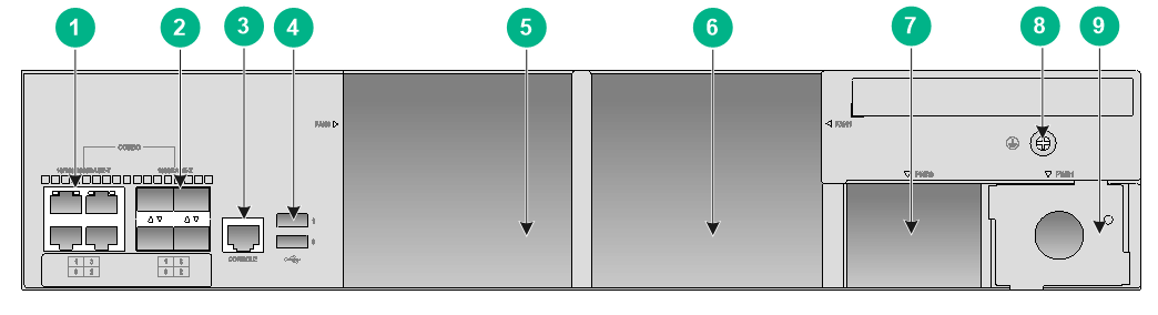
Front panel
On the front panel, the F5030/F5030-6GW/F5060/F5080/F5000-M/F5000-A firewall provides eight interface module slots and two drive slots.
Front panel
|
(1) Interface module slots (slots 1 through 8) |
(2) Drive slot HD0 |
|
(3) Drive slot HD1 |
(4) LEDs |
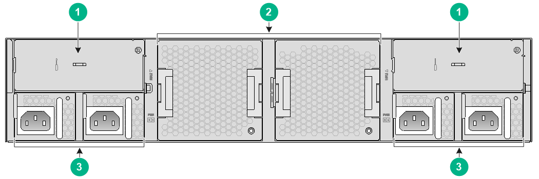
Rear panel
On the rear panel, the F5030/F5030-6GW/F5060/F5080/F5000-M/F5000-A firewall provides four combo interfaces (including one management Ethernet port), two USB ports, one console port, two fan tray slots, and two power module slots.
Rear panel
|
(1) 10/100/1000BASE-T copper Ethernet port (combo interface) |
|
|
(2) 1000BASE-X fiber Ethernet port (combo interface) |
|
|
(3) Console port |
(4) USB port (host mode, Type A connector) |
|
(5) Fan tray slot FAN0 |
(6) Fan tray slot FAN1 |
|
(7) Power module slot PWR0 |
(8) Grounding screw |
|
(9) Power module slot PWR1 |
(10) Management Ethernet port (MGMT) |
Interface numbering
The F5030/F5030-6GW/F5060/F5080/F5000-M/F5000-A firewall provides multiple types of ports including console ports, management Ethernet ports, 10/100/1000BASE-T Ethernet copper ports, 1000BASE-X Ethernet fiber ports, 10GBASE-R Ethernet fiber ports, and 40GBASE-R Ethernet fiber ports.
The ports are numbered in the interface-type X/Y/Z format.
· interface-type—Interface type.
· X—IRF member device ID.
· Y—Subslot number. The value is 0 for fixed ports on the firewall rear panel. The interface modules slots are numbered from 1 to 8.
· Z—Number marked for the port on the firewall real panel or interface module, starting from 0.
Example:
· The fixed ports on the firewall rear panel are numbered from GigabitEthernet 1/0/0 to GigabitEthernet 1/0/3. The management Ethernet port is numbered GigabitEthernet 1/0/0.
· If an NSQM1TG8A interface module is installed in slot 3 of the firewall, the ports on the interface module are numbered from Ten-GigabitEthernet 1/3/0 to Ten-GigabitEthernet 1/3/7.
F5030-6GW-G
Front panel
On the front panel, the F5030-6GW-G firewall provides the following ports, slots, and buttons:
· Twelve 10/100/1000BASE-T autosensing Ethernet copper ports.
· Four 40GBASE-R Ethernet fiber ports.
· Sixteen 10GBASE-R Ethernet fiber ports.
· Two USB ports.
· One console port.
· One Ethernet management port.
· One reset button (not supported in the current version).
· Four interface module slots.
· Two drive slots.
Front panel
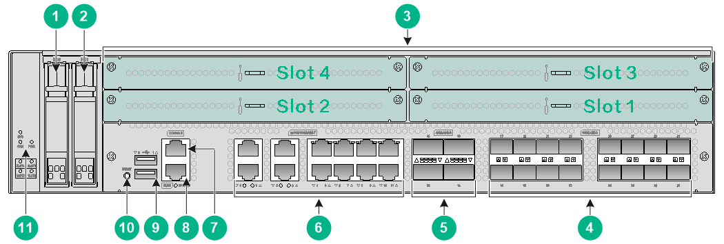
|
(1) Drive slot HD0 |
(2) Drive slot HD1 |
|
(3) Interface module slots (Slot 1 to Slot 4) |
(4) 10GBASE-R Ethernet fiber ports |
|
(5) 40GBASE-R Ethernet fiber ports |
(6) 10/100/1000BASE-T Ethernet copper ports |
|
(7) Console port |
(8) Management Ethernet port (0/MGMT) |
|
(9) USB port (host mode, type A) |
(10) Reset button (not supported in the current version) |
|
(11) LEDs |
|
Rear panel
On the rear panel, the F5030-6GW-G firewall provides four power module slots, two fan tray slots, and two slots reserved for future use.
Rear panel
|
(1) Reserved slots for future use |
(2) Fan tray slots |
|
(3) Power module slots |
|
Interface numbering
The firewall provides multiple types of ports including console ports, management Ethernet ports, 10/100/1000BASE-T Ethernet copper ports, 1000BASE-X Ethernet fiber ports, 10GBASE-R Ethernet fiber ports, and 40GBASE-R Ethernet fiber ports.
The ports are numbered in the interface-type X/Y/Z format.
· interface-type—Interface type.
· X—IRF member device ID.
· Y—Subslot number. The value is 0 for fixed ports on the firewall front panel. The interface modules slots are numbered from 1 to 4.
· Z—Number marked for the port on the firewall front panel or interface module, starting from 0.
Example:
· The fixed ports on the firewall front panel are numbered from GigabitEthernet 1/0/0 to GigabitEthernet 1/0/31.
· If an NS-NIMT-G4B interface module is installed in the slot 3 of the firewall, the ports on the interface module are numbered from Ten-GigabitEthernet 1/3/0 to Ten-GigabitEthernet 1/3/4.
F5030-D/F5060-D/F5080-D
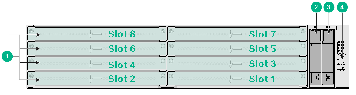
Front panel
On the front panel, the F5030-D/F5060-D/F5080-D firewall provides two MPU slots, six interface module slots, and two drive slots.
Front panel
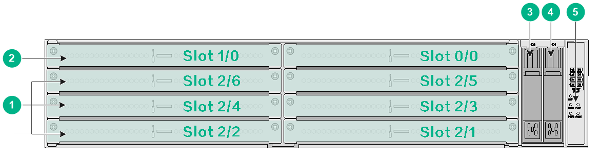
|
(1) Interface module slots (slots 2/1 through 2/6) |
(2) MPU slots (slots 0/0 and 1/0) |
|
(3) Drive slot HD0 |
(4) Drive slot HD1 |
|
(5) LEDs |
|
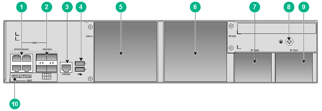
Rear panel
On the rear panel, the F5030-D/F5060-D/F5080-D firewall provides the following ports and slots:
· Four combo interfaces (including four 10/100/1000BASE-T autosensing copper Ethernet ports and four 1000BASE-X fiber Ethernet ports)
· Two USB ports
· One console port
· Two fan tray slots
· Two power module slots
Rear panel
|
(1) 10/100/1000BASE-T copper Ethernet port (combo interface) |
|
|
(2) 1000BASE-X fiber Ethernet port (combo interface) |
|
|
(3) Console port |
(4) USB port (host mode, Type A connector) |
|
(5) Fan tray slot FAN0 |
(6) Fan tray slot FAN1 |
|
(7) Power module slot PWR0 |
(8) Grounding screw |
|
(9) Power module slot PWR1 |
|
Interface numbering
The firewall provides multiple types of ports including console ports, management Ethernet ports, 10/100/1000BASE-T copper ports, 1000BASE-X fiber ports, 10GBASE-R fiber ports, and 40GBASE-R fiber ports.
The ports are numbered in the interface-type W/X/Y/Z format.
· interface-type—Interface type.
· W—IRF member device ID.
· X—Slot number of the firewall rear panel, MPU slot, or interface module slot. The MPU slots are numbered 0 and 1. The slot number for the firewall rear panel or interface module slot is 2.
· Y—Subslot number. The value is 0 for fixed ports on the MPU and firewall real panel. The interface modules slots are numbered from 1 to 6.
· Z—Number marked for the port on the firewall rear panel or module, starting from 0.
Example:
· If the NSQM1MPULA MPU is installed in slot 0/0 on the F5030-D/F5060-D/F5080-D firewall, the management Ethernet port on the MPU is numbered M-GigabitEthernet 1/0/0/0.
· If an NSQM1TG8A interface module is installed in slot 2/3 on the F5030-D/F5060-D/F5080-D firewall, the ports on the interface module are numbered from Ten-GigabitEthernet 1/2/3/0 to Ten-GigabitEthernet 1/2/3/7.
· The fixed ports on the device real panel are numbered from GigabitEthernet 1/2/0/0 to GigabitEthernet 1/2/0/3.
Slots
Slots on the firewall
|
Firewall model |
MPU slots |
Interface module slots |
Drive slots |
|
F5030/F5060/F5080/F5030-6GW |
N/A |
8 |
2 |
|
F5030-6GW-G |
N/A |
4 |
2 |
|
F5000-M/F5000-A |
N/A |
8 |
2 |
|
F5030-D/F5060-D/F5080-D |
2 |
6 |
2 |
FRU views
MPUs
The NSQM1MPULA MPU provides two USB ports, one console port, and one 100/1000BASE-TX management Ethernet port. Only slots 0/0 and 1/0 on the F5030-D/F5060-D/F5080-D firewall support the NSQM1MPULA MPU.
Front view
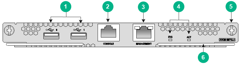
|
(1) USB port (host mode, Type A connector) |
(2) Console port (CONSOLE) |
|
(3) Management Ethernet port (MANAGEMENT) |
(4) LEDs |
|
(5) Captive screw |
(6) Ejector lever |
Interface modules
|
|
CAUTION: · Do not hot swap interface modules. · To install GE transceiver modules on 10GE fiber ports of an NSQM1TG8A or NSQM1G4XS4 interface module, install the interface module in slot 3 or slot 2/3. · By default, autonegotiation is disabled on GE fiber ports of an NSQM1G4XS4 interface module. If you have to switch the port transmission speed or duplex mode because the autonegotiation mode is inconsistent with that on the peer device, install the NSQM1G4XS4 interface module in slot 3 or slot 2/3. |
0 displays the slots available for interface module installation.
Interface module and device slot compatibility
|
Interface module |
F5030/F5060/F5080/F5030-6GW |
F5030-6GW-G |
F5000-M/F5000-A |
F5030-D/F5060-D/F5080-D |
|
NSQM1TG8A |
Slots 1 through 3 |
N/A |
Slots 1 through 3 |
Slots 2/1 through 2/3 |
|
NSQM1QG2A |
||||
|
NSQM1G4XS4 |
||||
|
NSQM1GT8A NSQM1GP8A NSQM1GT4PFCA |
Slots 4 through 8 |
N/A |
Slots 4 through 8 |
Slots 2/4 through 2/6 |
|
NS-NIM-GP4B NS-NIM-QG1A NS-NIM-TG4B |
N/A |
Slots 1 through 4 |
N/A |
N/A |
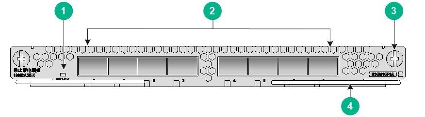
NSQM1TG8A
The NSQM1TG8A interface module provides eight 10GBASE-R fiber Ethernet ports.
NSQM1TG8A front view
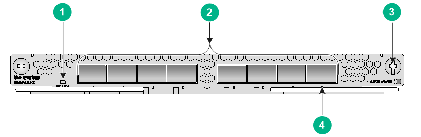
|
(1) LED |
(2) 10GBASE-R fiber Ethernet ports |
|
(3) Captive screw |
(4) Ejector lever |
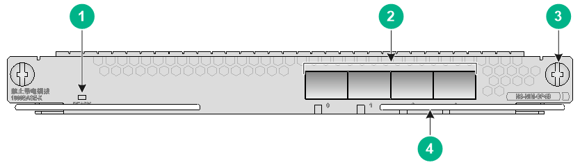
NSQM1QG2A
The NSQM1QG2A interface module provides two 40GBASE-R fiber Ethernet ports.
NSQM1QG2A front view
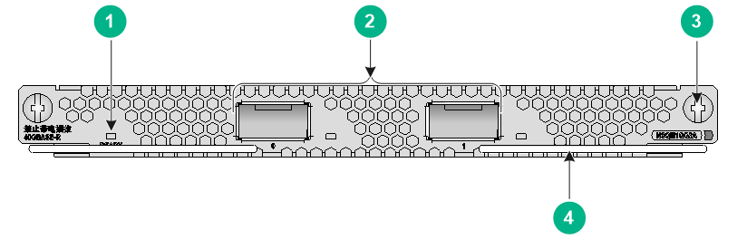
|
(1) LED |
(2) 40GBASE-R fiber Ethernet ports |
|
(3) Captive screw |
(4) Ejector lever |
NSQM1G4XS4
The NSQM1G4XS4 interface module provides four 10GBASE-R fiber Ethernet ports (10G-SR/LR) and four 1000BASE-X fiber Ethernet ports.
NSQM1G4XS4 front view
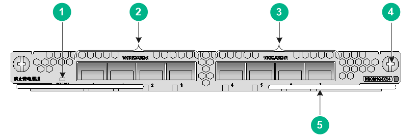
|
(1) LED |
(2) 1000BASE-X fiber Ethernet ports |
|
(3) 10GBASE-R fiber Ethernet ports |
(4) Captive screw |
|
(5) Ejector lever |
|
NSQM1GT8A
The NSQM1GT8A interface module provides eight 10/100/1000BASE-T copper ports.
NSQM1GT8A front view
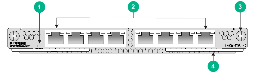
|
(1) LED |
(2) 10/100/1000BASE-T copper Ethernet ports |
|
(3) Captive screw |
(4) Ejector lever |
NSQM1GP8A
The NSQM1GP8A interface module provides eight 1000BASE-X fiber Ethernet ports.
NSQM1GP8A front view
|
(1) LED |
(2) 1000BASE-X fiber Ethernet ports |
|
(3) Captive screw |
(4) Ejector lever |
NSQM1GT4PFCA
The NSQM1GT4PFCA interface module provides four 10/100/1000BASE-T copper Ethernet ports that support the bypass function.
NSQM1GT4PFCA front view
|
(1) LED |
(2) 10/100/1000BASE-T copper Ethernet ports |
|
(3) Captive screw |
(4) Ejector lever |
NS-NIM-GP4B
The NS-NIM-GP4B interface module provides four 1000BASE-X fiber Ethernet ports.
NS-NIM-GP4B front view
|
(1) LED |
(2) 1000BASE-X fiber Ethernet ports |
|
(3) Captive screw |
(4) Ejector lever |
NS-NIM-QG1A
The NS-NIM-QG1A interface module provides one 40GBASE-R fiber Ethernet ports.
NS-NIM-QG1A front view
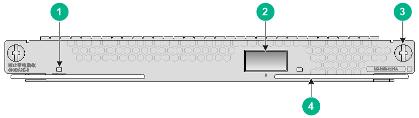
|
(1) LED |
(2) 40GBASE-R fiber Ethernet ports |
|
(3) Captive screw |
(4) Ejector lever |
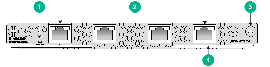
NS-NIM-TG4B
The NS-NIM-TG4B interface module provides four 10GBASE-R fiber Ethernet ports.
NS-NIM-TG4B front view
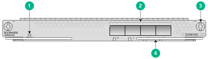
|
(1) LED |
(2) 10GBASE-R fiber Ethernet ports |
|
(3) Captive screw |
(4) Ejector lever |
Network data encryption modules
|
|
CAUTION: Do not hot swap network data encryption modules. |
The appearance of network data encryption modules varies by models. For more information, see H3C SecPath Firewall Network Data Encryption Module Guide.
0 describes the hardware and software compatibility with the network data encryption modules.
Hardware and software compatibility with the network data encryption modules
|
Network data encryption module |
Applicable firewalls |
Applicable slots |
Applicable software versions |
|
NS-HTIM-GMG2A |
F5030, F5060, F5080, F5030-6GW F5000-M, F5000-A |
Slot 1 |
R9628P24 and later |
|
NS-HTIM-GMG2B |
F5030-D, F5060-D, F5080-D |
Slot 2/1 |
R9620P2410 and later |
Power modules
The firewall supports AC and DC power modules and supports power module redundancy.
No power modules are provided with the firewall. Purchase AC or DC power modules for the firewall as needed.
The F5030/F5030-6GW/F5060/F5080/F5000-M/F5000-A/F5030-D/F5060-D/F5080-D firewall came with power module slot PWR0 installed with a filler panel and power module slot PWR1 empty. To use two power modules on the firewall, make sure they are the same in specifications. If two power modules are installed, you can hot swap one.
The F5030-6GW-G provides four power module slots (PWR0, PWR1, PWR2, and PWR3) and came with filler panels in three power module slots.
For the power module specifications, see "Power module specifications."
Power modules available for the firewall
|
Device model |
Power module quantity and type |
Available power module models |
|
F5030/F5030-6GW/F5060/F5080/F5000-M/F5000-A/F5030-D/F5060-D/F5080-D |
2 removable power modules |
PSR650B-12A1, PSR650B-12D1 |
|
F5030-6GW-G |
4 removable power modules |
PSR450-12A1, PSR450-12D |
AC power module
PSR450-12A1
The PSR450-12A1 power module (product code PSR450-12A1) provides a rated output power of 450 W.
PSR450-12A1 power module
|
(1) Latch |
(2) LED |
|
(3) Handle |
(4) Power receptacle |
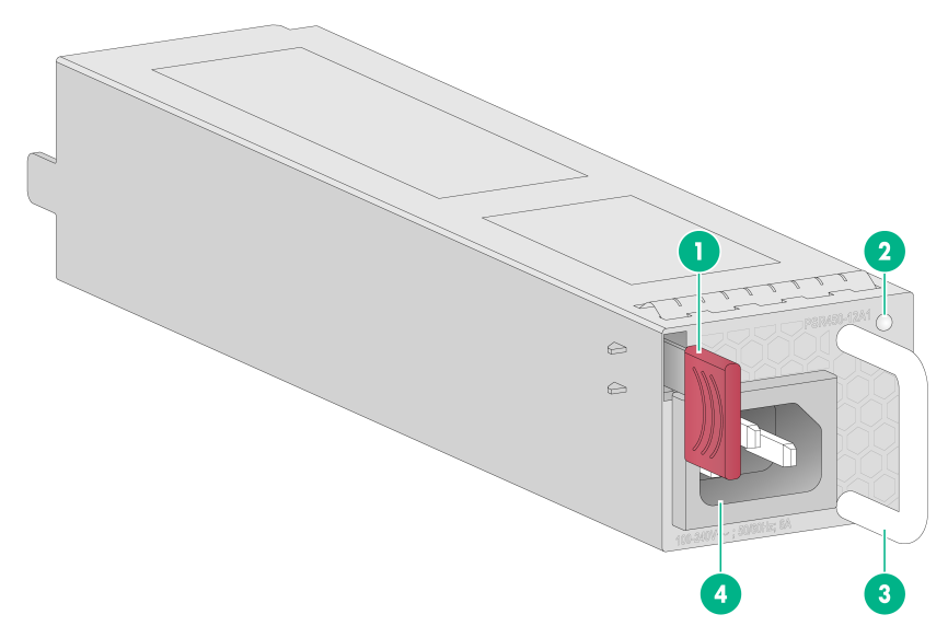
PSR650B-12A1
The PSR650B-12A1 AC power module (product code PSR650B-12A1-A) provides a maximum output power of 650 W.
AC power module front view

|
(1) Retaining latch |
(2) Handle |
|
(3) Power receptacle |
|
DC power module
PSR450-12D
The PSR450-12D DC power module (product code PSR450-12D) provides a rated output power of 450 W.
PSR450-12D DC power module
|
(1) Latch |
(2) LED |
|
(3) Handle |
(4) Power receptacle |
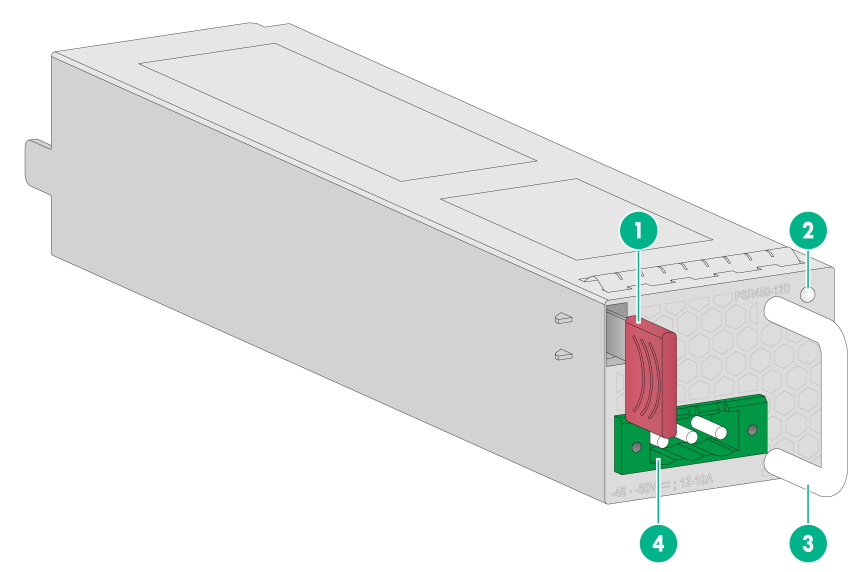
PSR650B-12D1
The PSR650B-12D1 DC power module (product code PSR650B-12D1-A) provides a maximum output power of 650 W.
DC power module front view
|
(1) Retaining latch |
(2) Handle |
|
(3) Power receptacle |
|
Fan trays
The firewall provides two fan tray slots FAN0 and FAN1. No fan trays are provided with the firewall. Purchase fan trays for the firewall as required.
The FAN-20F-2-A, LSWM1BFANSC, LSWM1BFANSCB and FAN-20B-2-A fan trays are available for the firewall. The FAN-20F-2-A and LSWM1BFANSC fan tray provides power module-side intake and port-side exhaust airflow. The FAN-20B-2-A and LSWM1BFANSCB fan tray provides port-side intake and power module-side exhaust airflow. For the fan tray specifications, see "Fan tray specifications."
To ensure adequate heat dissipation, the firewall must have two fan trays of the same model installed when it is operating.
FAN-20F-2-A or LSWM1BFANSC fan tray
FAN-20F-2-A or LSWM1BFANSC fan tray
|
(1) Handle |
(2) Alarm LED |
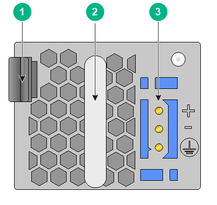
FAN-20B-2-A or LSWM1BFANSCB fan tray
FAN-20B-2-A or LSWM1BFANSCB fan tray
|
(1) Handle |
(2) Alarm LED |
Dimensions and weights
The weight of the firewall includes the chassis and its removable components, as shown in 0.
|
Model |
Dimensions (H × W × D) |
Weight |
|
F5030/F5030-6GW/F5060/F5080/F5030-D/F5060-D/F5080-D/F5000-M/F5000-A chassis |
88.1 × 440 × 660 mm (3.47 × 17.32 × 25.98 in) (excluding rubber feet and mounting brackets) |
20.1 kg (44.31 lb) |
|
F5030-6GW-G |
88.1 × 440 × 660 mm (3.47 × 17.32 × 25.98 in) (excluding rubber feet and mounting brackets) |
15 kg (33.07 lb) |
|
MPU |
||
|
NSQM1MPULA |
19.8 × 189 × 212.4 mm (0.78 × 7.44 × 8.36 in) |
0.6 kg (1.32 lb) |
|
Interface module |
||
|
NSQM1TG8A |
19.8 × 189 × 212.4 mm (0.78 × 7.44 × 8.36 in) |
0.55 kg (1.21 lb) |
|
NSQM1QG2A |
19.8 × 189 × 212.4 mm (0.78 × 7.44 × 8.36 in) |
0.55 kg (1.21 lb) |
|
NSQM1G4XS4 |
19.8 × 189 × 212.4 mm (0.78 × 7.44 × 8.36 in) |
0.54 kg (1.19 lb) |
|
NSQM1GT8A |
19.8 × 189 × 212.4 mm (0.78 × 7.44 × 8.36 in) |
0.55 kg (1.21 lb) |
|
NSQM1GP8A |
19.8 × 189 × 212.4 mm (0.78 × 7.44 × 8.36 in) |
0.55 kg (1.21 lb) |
|
NSQM1GT4PFCA |
19.8 × 189 × 212.4 mm (0.78 × 7.44 × 8.36 in) |
0.6 kg (1.32 lb) |
|
NS-NIM-GP4B |
19.8 × 189 × 212.4 mm (0.78 × 7.44 × 8.36 in) |
0.6 kg (1.32 lb) |
|
NS-NIM-Q1GA |
19.8 × 189 × 212.4 mm (0.78 × 7.44 × 8.36 in) |
0. 5 kg (1.1 lb) |
|
NS-NIM-TG4B |
19.8 × 189 × 212.4 mm (0.78 × 7.44 × 8.36 in) |
0.6 kg (1.32 lb) |
Memory and storage media
Memory and storage media specifications
|
Firewall model |
Memory |
|
F5030/F5030-D/F5030-6GW |
16GB DDR3 |
|
F5030-6GW-G |
32GB DDR4 |
|
F5000-M/F5000-A |
16GB DDR3 |
|
F5060/F5060-D |
32GB DDR3 |
|
F5080/F5080-D |
64GB DDR3 |
Power consumption
The power consumption of the firewall is the power consumption of the chassis plus the power consumption of the MPUs and interface modules, as shown in 0.
|
Item |
Specification |
|
Firewall chassis |
|
|
F5030/F5030-6GW/F5060/F5080/F5000-M |
191 W |
|
F5030-6GW-G |
369 W |
|
F5000-A |
199 W |
|
F5030-D/F5060-D/F5080-D |
250 W |
|
MPU |
|
|
NSQM1MPULA |
7.50 W |
|
Interface module |
|
|
NSQM1TG8A |
12.96 W |
|
NSQM1QG2A |
6.40 W |
|
NSQM1G4XS4 |
6.46 W |
|
NSQM1GT8A |
3.03 W |
|
NSQM1GP8A |
8.15 W |
|
NSQM1GT4PFCA |
5.78 W |
|
NS-NIM-GP4B |
7.6 W |
|
NS-NIM-Q1GA |
6.1 W |
|
NS-NIM-TG4B |
7.6 W |
Network data encryption module specifications
NS-HTIM-GMG2A specifications
|
Item |
Specification |
|
Model |
NS-HTIM-GMG2A |
|
Dimensions (H × W × D) |
40.1 × 189.0 × 212.4 mm (1.58 × 7.44 × 8.36 in) |
|
Weight |
0.6 kg (1.32 lb) |
|
Maximum power |
7 W |
NS-HTIM-GMG2B specifications
|
Item |
Specification |
|
Model |
NS-HTIM-GMG2B |
|
Dimensions (H × W × D) |
40.1 × 189.0 × 212.4 mm (1.58 × 7.44 × 8.36 in) |
|
Weight |
0.6 kg (1.32 lb) |
|
Maximum power |
7 W |
Power module specifications
AC power module specifications
PSR450-12A1 power module specifications
|
Item |
Specification |
|
Model |
PSR450-12A1 |
|
Rated input voltage range |
100 VAC to 240 VAC @ 50 Hz or 60 Hz |
|
Maximum input current |
7 A |
|
Maximum power |
450 W |
PSR650B-12A1 power module specifications
|
Item |
Specification |
|
Model |
PSR650B-12A1 |
|
Rated input voltage range |
100 VAC to 240 VAC @ 50 Hz or 60 Hz |
|
Maximum input current |
5 A to 10 A |
|
Maximum power |
650 W |
DC power module specifications
PSR450-12D power module specifications
|
Item |
Specification |
|
Model |
PSR450-12D |
|
Rated input voltage range |
–40 VDC to –60 VDC |
|
Maximum input current |
15 A |
|
Maximum power |
450 W |
PSR650B-12D1 power module specifications
|
Item |
Specification |
|
Model |
PSR650B-12D1 |
|
Rated input voltage range |
–40 VDC to –60 VDC |
|
Maximum input current |
12 A to 22 A |
|
Maximum power |
650 W |
Fan tray specifications
|
Item |
Specifications |
|
Dimensions (H × W × D), excluding the handle |
84.5 × 87 × 209 mm (3.33 × 3.43 × 8.23 in) |
|
Airflow direction |
FAN-20F-2-A/LSWM1BFANSC: From the power module side to the port side |
|
FAN-20B-2-A/LSWM1BFANSCB: From the port side to the power module side |
|
|
Hot swapping |
Supported |
|
Max airflow volume |
120 CFM |
|
Max power consumption |
57 W |
|
Operating voltage |
12 VDC |
Drive specifications
NS-SSD-480G-SATA-SFF specifications
|
Item |
Specification |
|
Dimensions (H × W × D) |
19 × 75.7 × 118.4 mm (0.75 × 2.98 × 4.66 in) |
|
Weight |
0.07 kg (0.15 lb) |
|
Hot swapping |
Not supported |
|
Capacity |
480 GB |
|
Operating temperature |
0°C to 45°C (32°F to 113°F) |
|
Power consumption |
3 W |
Port specifications
Console port
Console port specifications
|
Item |
Specification |
|
Connector |
RJ-45 |
|
Standard compliant |
RS-232 |
|
Baud rate |
9600 bps (default) to 115200 bps |
|
Cable type |
Common asynchronous serial port cable |
|
Transmission distance |
≤ 15 m (49.21 ft) |
|
Services |
· Connection to an ASCII terminal · Connection to the serial port of a local PC to run the terminal emulation program · CLI |
GE copper port
GE copper port specifications
|
Item |
Specification |
|
Connector |
RJ-45 |
|
Standard compliance |
802.3, 802.3u, and 802.3ab |
|
Interface type |
MDI/MDI-X autosensing |
|
Cable type |
Category 5 or higher twisted pair cable |
|
Transmission distance |
100 m (328.08 ft) |
|
Interface speed and duplex mode |
10 Mbps, half/full-duplex 100 Mbps, half/full-duplex 1000 Mbps, full-duplex |
|
|
NOTE: The media dependent interface (MDI) standard is typically used on the Ethernet port of network adapters. The media dependent interface crossover (MDI-X) standard is typically used on hubs or LAN switches. |
Transceiver modules for GE copper ports
GE copper port transceiver module specifications
|
Item |
Specification |
|
Connector |
RJ-45 |
|
Transceiver module type |
SFP |
|
Cable type |
Category 5 or higher twisted pair cable |
|
Transmission distance |
100 m (328.08 ft) |
|
Duplex mode |
Full duplex mode |
GE SF transceiver module specifications
|
Transceiver module model |
Transmission distance |
Transmission rate |
Connector type |
|
SFP-GE-T |
100 m (328.08 ft) |
1250 Mbps |
RJ-45 |
|
SFP-GE-T-D |
100 m (328.08 ft) |
1250 Mbps |
RJ-45 |
GE fiber port
GE fiber port specifications
|
Item |
Specification |
|
Connector type |
LC |
|
Transceiver module type |
SFP |
|
Standard compliance |
1000BASE-X |
|
Interface speed |
1000 Mbps |
|
Duplex mode |
Full duplex |
1000BASE-X SFP transceiver module specifications (1)
|
Transceiver module |
Central wavelength (nm) |
Fiber mode |
Fiber diameter (µm) |
Mode bandwidth (MHz*km) |
|
SFP-GE-SX-MM850-A |
850 |
MMF |
50/125 |
500 |
|
400 |
||||
|
62.5/125 |
200 |
|||
|
160 |
||||
|
160 |
||||
|
SFP-GE-LX-SM1310-A |
1310 |
SMF |
9/125 |
N/A |
|
MMF |
50/125 |
500/400 |
||
|
62.5/125 |
500 |
|||
|
SFP-GE-LH40-SM1310 |
1310 |
SMF |
9/125 |
N/A |
|
SFP-GE-LH40-SM1550 |
1550 |
SMF |
9/125 |
N/A |
|
SFP-GE-LH80-SM1550 |
1550 |
SMF |
9/125 |
N/A |
|
SFP-GE-LH100-SM1550 |
1550 |
SMF |
9/125 |
N/A |
|
SFP-GE-LX-SM1310-D |
1310 |
SMF |
9/125 |
N/A |
|
SFP-GE-SX-MM850-D |
850 |
MMF |
50/125 |
500 |
|
400 |
||||
|
62.5/125 |
200 |
|||
|
160 |
1000BASE-X SFP transceiver module specifications (2)
|
Transceiver module |
Transmission distance |
Transmitted optical power (dBm) |
Received optical power (dBm) |
|
SFP-GE-SX-MM850-A |
550 m (1804.46 ft) |
–9.5 to 0 |
–17 to –3 |
|
500 m (1640.42 ft) |
|||
|
275 m (902.23 ft) |
|||
|
220 m (721.78 ft) |
|||
|
220 m (721.78 ft) |
|||
|
SFP-GE-LX-SM1310-A |
10 km (6.21 miles) |
–9.5 to –3 |
–20 to –3 |
|
550 m (1804.46 ft) |
|||
|
550 m (1804.46 ft) |
|||
|
SFP-GE-LH40-SM1310 |
40 km (24.85 miles) |
–5 to +5 |
–22 to –3 |
|
SFP-GE-LH40-SM1550 |
40 km (24.85 miles) |
–4 to +1 |
–21 to –3 |
|
SFP-GE-LH80-SM1550 |
80 km (49.71 miles) |
–4 to +5 |
–22 to –3 |
|
SFP-GE-LH100-SM1550 |
100 km (62.14 miles) |
0 to +5 |
–30 to –9 |
|
SFP-GE-LX-SM1310-D |
10 km (6.21 miles) |
–9.5 to –3 |
–20 to –3 |
|
SFP-GE-SX-MM850-D |
550 m (1804.46 ft) |
–9.5 to 0 |
–17 to –3 |
|
500 m (1640.42 ft) |
|||
|
275 m (902.23 ft) |
|||
|
220 m (721.78 ft) |
10 GE fiber port
10 GE fiber port specifications
|
Item |
Specification |
|
Connector type |
LC |
|
Transceiver module type |
SFP+ |
|
Standard compliance |
10GBASE-R |
|
Interface speed |
LAN PHY: 10 Gbps |
SFP+ transceiver module specifications (1)
|
Transceiver module |
Central wavelength (nm) |
Fiber mode |
Fiber diameter (µm) |
Mode bandwidth (MHz*km) |
|||
|
SFP-XG-SX-MM850-A |
850 |
MMF |
50/125 |
2000 |
|||
|
500 |
|||||||
|
400 |
|||||||
|
62.5/125 |
200 |
||||||
|
160 |
|||||||
|
160 |
|||||||
|
SFP-XG-LX220-MM1310 |
1310 |
MMF |
50/125 |
1500 |
|||
|
500 |
|||||||
|
400 |
|||||||
|
62.5/125 |
200 |
||||||
|
160 |
|||||||
|
SFP-XG-LX-SM1310 |
1310 |
SMF |
9/125 |
N/A |
|||
|
SFP-XG-LH40-SM1550 |
1550 |
SMF |
9/125 |
N/A |
|||
|
SFP-XG-SX-MM850-D |
850 |
MMF |
50/125 |
2000 |
|||
|
500 |
|||||||
|
400 |
|||||||
|
62.5/125 |
200 |
||||||
|
160 |
|||||||
SFP+ transceiver module specifications (2)
|
Transceiver module |
Transmission distance |
Transmission speed |
Transmitted optical power (dBm) |
Received optical power (dBm) |
|
SFP-XG-SX-MM850-A |
300 m (984.25 ft) |
10.31 Gbps |
–7.3 to –1 |
–9.9 to +0.5 |
|
82 m (269.03 ft) |
||||
|
66 m (216.54 ft) |
||||
|
33 m (108.27 ft) |
||||
|
26 m (85.30 ft) |
||||
|
8 m (26.25 ft) |
||||
|
SFP-XG-LX220-MM1310 |
220 m (721.78 ft) |
10.31 Gbps |
–6.5 to +0.5 |
–6.5 to +1.5 |
|
220 m (721.78 ft) |
||||
|
100 m (328.08 ft) |
||||
|
220 m (721.78 ft) |
||||
|
220 m (721.78 ft) |
||||
|
SFP-XG-LX-SM1310 |
10 km (6.21 miles) |
10.31 Gbps |
–8.2 to +0.5 |
–14.4 to +0.5 |
|
SFP-XG-LH40-SM1550 |
40 km (24.85 miles) |
10.31 Gbps |
–4.7 to +4 |
–15.8 to –1 |
|
SFP-XG-SX-MM850-D |
300 m (984.25 ft) |
10.31 Gbps |
–7.3 to –1 |
–9.9 to +0.5 |
|
82 m (269.029 ft) |
||||
|
66 m (216.54 ft) |
||||
|
33 m (108.27 ft) |
||||
|
26 m (85.30 ft) |
40 GE fiber port
QSFP+ transceiver modules (MPO port)
QSFP+ transceiver modules (MPO port) provide a transmission rate of 40 Gbps and uses an MPO connector.
40 GE fiber port specifications
|
Item |
Specification |
|
Connector type |
MPO |
|
Transceiver module type |
QSFP+ |
|
Standard compliance |
40GBASE-R |
|
Interface speed |
LAN PHY: 40 Gbps |
QSFP+ transceiver module (MPO port) specifications (1)
|
Transceiver module |
Central wavelength (nm) |
Fiber mode |
Fiber diameter (µm) |
Mode bandwidth (MHz*km) |
|
QSFP-40G-SR4-MM850 |
850 |
MMF |
50/125 |
2000 |
|
4700 |
||||
|
QSFP-40G-CSR4-MM850 |
850 |
MMF |
50/125 |
2000 |
|
4700 |
QSFP+ transceiver module (MPO port) specifications (2)
|
Transceiver module |
Transmission distance |
Transmission speed |
Transmitted optical power (dBm) |
Received optical power (dBm) |
|
QSFP-40G-SR4-MM850 |
100 m (328.08 ft) |
40 Gbps |
–7.6 to 0 |
–9.5 to +2.4 |
|
150 m (492.13 ft) |
||||
|
QSFP-40G-CSR4-MM850 |
300 m (984.25 ft) |
40 Gbps |
–7.6 to 0 |
–9.9 to +2.4 |
|
400 m (1312.34 ft) |
QSFP+ transceiver modules (LC port)
QSFP+ transceiver modules (LC port) provide a transmission rate of 40 Gbps and uses an LC connector.
40 GE port specifications
|
Item |
Specification |
|
Connector type |
LC |
|
Transceiver module type |
QSFP+ |
|
Standard compliance |
40GBASE-R |
|
Interface speed |
LAN PHY: 40 Gbps |
QSFP+ transceiver module (LC port) specifications (1)
|
Transceiver module |
Central wavelength (nm) |
Fiber mode |
Fiber diameter (µm) |
Mode bandwidth (MHz*km) |
Transmission distance |
Power (dBm) |
|
|
Tx power |
Rx power |
||||||
|
QSFP-40G-BIDI-SR-MM850 |
Two lanes: · 850 · 900 |
MMF |
50/125 |
2000 |
100 m (328.084 ft) |
–4 to +5 |
–6 to +5 |
|
4700 |
150 m (492.13 ft) |
||||||
|
QSFP-40G-LR4L-WDM1300 |
Four lanes: · 1271 · 1291 · 1311 · 1331 |
SMF |
9/125 |
N/A |
2 km (1.24 miles) |
–10 to +2.3 |
–11.5 to +2.3 |
|
QSFP-40G-ER4-WDM1300 |
Four lanes: · 1271 · 1291 · 1311 · 1331 |
SMF |
9/125 |
N/A |
40 km (24.85 miles) |
–2.7 to +4.5 |
–21.2 to –4.5 |
|
QSFP-40G-LR4-WDM1300 |
Four lanes: · 1271 · 1291 · 1311 · 1331 |
SMF |
9/125 |
N/A |
10 km (6.21 miles) |
–7 to +2.3 |
–13.7 to +2.3 |
|
QSFP-40G-BIDI-WDM850 |
Four lanes: · 850 · 880 · 910 · 940 |
MMF |
50/125 |
2000 |
240 m (787.40 ft) |
–7.6 to +3 |
–9 to +3 |
Appendix B LEDs
F5030/F5030-6GW/F5060/F5080/F5000-M/F5000-A/F5030-D/F5060-D/F5080-D
This section uses the LEDs on the F5030 firewall as an example.
LEDs
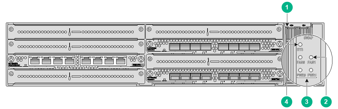
|
(1) Drive status LED |
(2) Fan status LEDs |
|
(3) Power module LEDs |
(4) System status LED |
LEDs
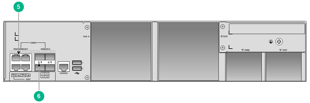
|
(5) Ethernet copper port LED (combo interface) |
(6) Ethernet fiber port LED (combo interface) |
Front panel and rear panel LED description
|
LED |
Mark |
Status |
Description |
|
Drive LEDs |
HD0 and HD1 |
Flashing green |
Data is being written in or read from the drive. |
|
Steady green |
The drive has finished the initialization and is operating correctly. |
||
|
Off |
The drive is not in position or has failed. |
||
|
Fan status LEDs |
FAN0 and FAN1 |
Steady green |
The fan tray is operating correctly. |
|
Off |
The fan tray has failed. |
||
|
Power module LEDs |
PWR0 and PWR1 |
Steady green |
The power module is operating correctly. |
|
Off |
The power module is not in position or has failed. |
||
|
System status LED |
SYS |
Flashing green (1 Hz) |
The firewall is operating correctly. |
|
Flashing green (8 Hz) |
The system is starting or loading software. |
||
|
Off |
The firewall is not powered on or has failed. |
||
|
Ethernet copper port LED (combo interface) |
10/100/1000BASE-T |
Flashing green |
The port is receiving or sending data. |
|
Steady green |
A link is present. |
||
|
Off |
No link is present. |
||
|
Ethernet fiber port LED (combo interface) |
1000BASE-X |
Flashing green |
The port is receiving or sending data at 1000 Mbps. |
|
Steady green |
A 1000 Mbps link is present. |
||
|
Off |
No link is present. |
F5030-GW-G
LEDs
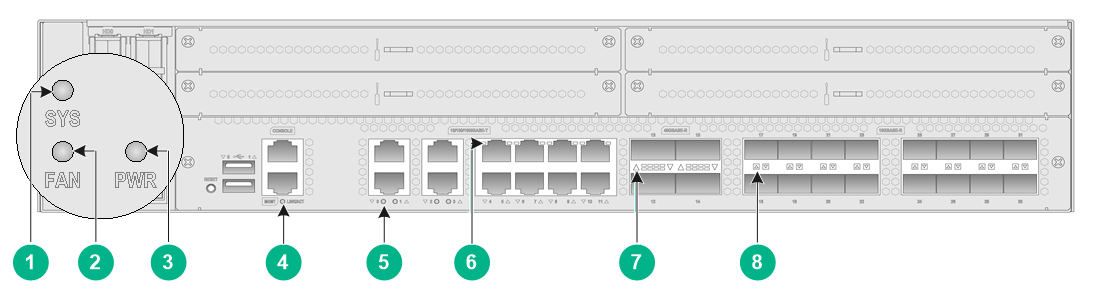
|
(1) System status LED |
(2) Fan status LED |
|
(3) Power module LED |
(4) Management Ethernet copper port LED |
|
(5) Ethernet copper port LED |
(6) Ethernet copper port LED |
|
(7) 10GBASE-R fiber port LED |
(8) 40GBASE-R fiber port LED |
Front panel and rear panel LED description
|
LED |
Mark |
Status |
Description |
|
System status LED |
SYS |
Flashing green (1 Hz) |
The firewall is operating correctly. |
|
Flashing green (8 Hz) |
The system is starting or loading software. |
||
|
Off |
The firewall is not powered on or has failed. |
||
|
Fan status LEDs |
FAN0 and FAN1 |
Steady green |
The fan tray is operating correctly. |
|
Off |
The fan tray has failed. |
||
|
Power module LEDs |
PWR0 and PWR1 |
Steady green |
The power module is operating correctly. |
|
Off |
The power module is not in position or has failed. |
||
|
Management Ethernet copper port LED |
MGMT |
Flashing green |
The port is receiving or sending data. |
|
Steady green |
A link is present. |
||
|
Off |
No link is present. |
||
|
Ethernet copper port LED |
10/100/1000BASE-T |
Flashing green |
The port is receiving or sending data. |
|
Steady green |
A link is present. |
||
|
Off |
No link is present. |
||
|
10GBASE-R fiber port LED |
10GBASE-R |
Flashing green |
The port is receiving or sending data at 10 Gbps. |
|
Steady green |
A 10 Gbps link is present. |
||
|
Off |
No link is present. |
||
|
40GBASE-R fiber port LED |
40GBASE-R |
Flashing green |
The port is receiving or sending data at 40 Gbps. |
|
Steady green |
A 40 Gbps link is present. |
||
|
Off |
No link is present. |
|
|
NOTE: The slot LED (SLOT) is reserved for future use. |
MPU LEDs
LEDs
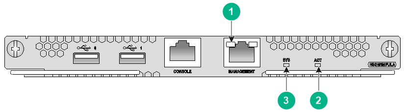
|
(1) Management port LED |
(2) ACT LED |
|
(3) System LED |
|
MPU LED description
|
LED |
Mark |
Status |
Description |
|
Management port LED |
MANAGEMENT |
Flashing yellow |
The port is receiving or sending data at a low speed. |
|
Steady yellow |
A low-speed link is present. |
||
|
Flashing green |
The port is receiving or sending data at a high speed. |
||
|
Steady green |
A high-speed link is present. |
||
|
Off |
No link is present. |
||
|
ACT LED |
ACT |
Steady green |
The MPU is the active MPU. |
|
Off |
The MPU is the standby MPU. |
||
|
System LED |
SYS |
Flashing green (0.5 Hz) |
The system is operating correctly. |
|
Flashing green (4 Hz) |
The system is loading software. |
||
|
Steady green |
The system has failed. |
Interface module LEDs
The Interface modules use similar LEDs. This section uses the LEDs on the NSQM1TG8A and NSQM1GT8A firewall as an example.
LEDs
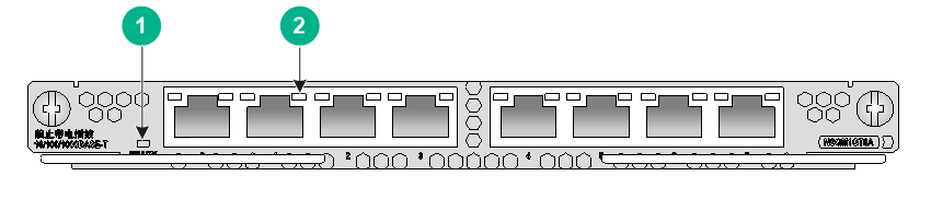
LEDs
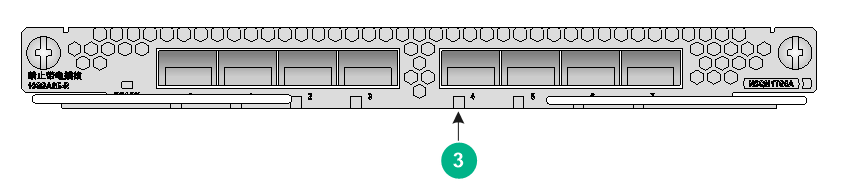
|
(1) Ready LED |
(2) Copper Ethernet port LED |
|
(3) Fiber Ethernet port LED |
|
Interface module LED description
|
LED |
Mark |
Status |
Description |
|
Ready LED |
READY |
Flashing green (1 Hz) |
The system is operating correctly. |
|
Flashing green (8 Hz) |
The system is starting. |
||
|
Off |
The system has failed. |
||
|
Copper Ethernet port LED |
10/100/1000BASE-T |
Flashing green |
The port is receiving or sending data. |
|
Steady green |
A link is present. |
||
|
Off |
No link is present. |
||
|
Fiber Ethernet port LED |
1000BASE-X |
Flashing green |
The port is receiving or sending data at 1000 Mbps. |
|
Steady green |
A 1000 Mbps link is present. |
||
|
Off |
No link is present. |
||
|
10GBASE-R |
Flashing green |
The port is receiving or sending data at 10 Gbps. |
|
|
Steady green |
A 10 Gbps link is present. |
||
|
Off |
No link is present. |
||
|
40GBASE-R |
Flashing green |
The port is receiving or sending data at 40 Gbps. |
|
|
Steady green |
A 40 Gbps link is present. |
||
|
Off |
No link is present. |
Appendix C Cables
Console cable
A console cable is an 8-core shielded cable with a crimped RJ-45 connector at one end and a DB-9 female connector at the other end. The RJ-45 connector is for connecting to the console port of the firewall, and the DB-9 female connector is for connecting to the serial port on the configuration terminal.
Console cable
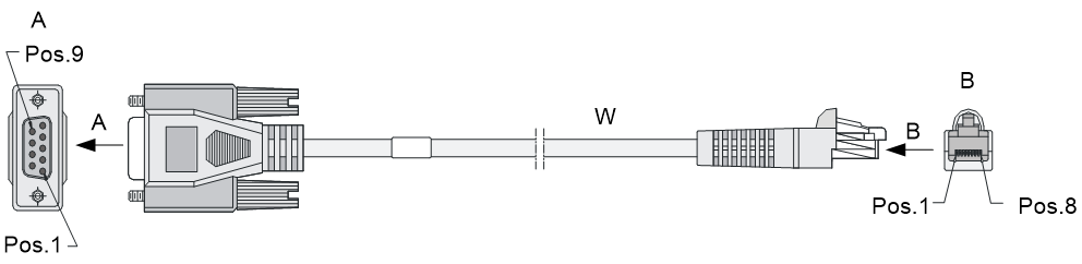
Console cable connection
|
RJ-45 |
Signal |
Direction |
DB-9 |
|
1 |
RTS |
← |
7 |
|
2 |
DTR |
← |
4 |
|
3 |
TXD |
← |
3 |
|
4 |
CD |
→ |
1 |
|
5 |
GND |
- |
5 |
|
6 |
RXD |
→ |
2 |
|
7 |
DSR |
→ |
6 |
|
8 |
CTS |
→ |
8 |
Ethernet twisted pair cable
Introduction
An Ethernet twisted pair cable consists of four pairs of insulated copper wires twisted together. Every wire uses a different color, and has a diameter of about 1 mm (0.04 in). A pair of twisted copper cables can cancel the electromagnetic radiation of each other, and reduce interference of external sources. An Ethernet twisted pair cable mainly transmits analog signals and is advantageous in transmitting data over shorter distances. It is the commonly used transmission media of the Ethernet. The maximum transmission distance of the Ethernet twisted pair cable is 100 m (328.08 ft). To extend the transmission distance, you can connect two twisted pair cable segments with a repeater. At most four repeaters can be added, which means five segments can be joined together to provide a transmission distance of 500 m (1640.42 ft).
Ethernet twisted pair cables can be classified into category 3, category 4, category 5, category 5e, category 6, and category 7 cables based on performance. In LANs, category 5, category 5e, and category 6 are commonly used.
Description for commonly used Ethernet twisted pair cables
|
Type |
Description |
|
Category 5 |
Suitable for data transmission at a maximum speed of 100 Mbps |
|
Category 5e |
Suitable for data transmission at a maximum speed of 1000 Mbps |
|
Category 6 |
Suitable for data transmission at a speed higher than 1 Gbps |
Based on whether a metal shielding is used, Ethernet twisted pair cables can be classified into shielded twisted pair (STP) and unshielded twisted pair (UTP). An STP cable provides a metallic braid between the twisted pairs and the outer jacket. This metallic braid helps reduce radiation, prevent information from being listened, and eliminate external electromagnetic interference (EMI) of external sources. STPs have strict application requirements and are expensive although they provide better EMI prevention performance than UTPs, so in most LANs, UTPs are commonly used.
An Ethernet twisted pair cable connects network devices through the RJ-45 connectors at the two ends. 0 shows the pinouts of an RJ-45 connector.
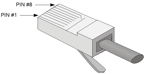
|
|
NOTE: The RJ-45 Ethernet ports of the firewall use category 5 or higher Ethernet twisted pair cables for connection. |
EIA/TIA cabling specifications define two standards, 568A and 568B, for cable pinouts.
· Standard 568A—pin 1: white/green stripe, pin 2: green solid, pin 3: white/orange stripe, pin 4: blue solid, pin 5: white/blue stripe, pin 6: orange solid, pin 7: white/brown stripe, pin 8: brown solid.
· Standard 568B—pin 1: white/orange stripe, pin 2: orange solid, pin 3: white/green stripe, pin 4: blue solid, pin 5: white/blue stripe, pin 6: green solid, pin 7: white/brown stripe, pin 8: brown solid.
Ethernet twisted pair cables can be classified into straight-through and crossover cables based on their pinouts.
· Straight-through—The pinouts at both ends are T568B compliant, as shown in 0.
· Crossover—The pinouts are T568B compliant at one end and T568A compliant at the other end, as shown in 0.

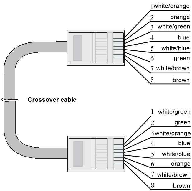
Select an Ethernet twisted pair cable according to the RJ-45 Ethernet port type on your device. An RJ-45 Ethernet port can be MDI (for routers and PCs) or MDIX (for switches). 0 and 0 show their pinouts.
|
Pin |
10Base-T/100Base-TX |
1000Base-T |
||
|
Signal |
Function |
Signal |
Function |
|
|
1 |
Tx+ |
Sends data |
BIDA+ |
Bi-directional data cable A+ |
|
2 |
Tx- |
Sends data |
BIDA- |
Bi-directional data cable A- |
|
3 |
Rx+ |
Receives data |
BIDB+ |
Bi-directional data cable B+ |
|
4 |
Reserved |
N/A |
BIDC+ |
Bi-directional data cable C+ |
|
5 |
Reserved |
N/A |
BIDC- |
Bi-directional data cable C- |
|
6 |
Rx- |
Receives data |
BIDB- |
Bi-directional data cable B- |
|
7 |
Reserved |
N/A |
BIDD+ |
Bi-directional data cable D+ |
|
8 |
Reserved |
N/A |
BIDD- |
Bi-directional data cable D- |
|
Pin |
10Base-T/100Base-TX |
1000Base-T |
||
|
Signal |
Function |
Signal |
Function |
|
|
1 |
Rx+ |
Receives data |
BIDB+ |
Bi-directional data cable B+ |
|
2 |
Rx- |
Receives data |
BIDB- |
Bi-directional data cable B- |
|
3 |
Tx+ |
Sends data |
BIDA+ |
Bi-directional data cable A+ |
|
4 |
Reserved |
N/A |
BIDD+ |
Bi-directional data cable D+ |
|
5 |
Reserved |
N/A |
BIDD- |
Bi-directional data cable D- |
|
6 |
Tx- |
Sends data |
BIDA- |
Bi-directional data cable A- |
|
7 |
Reserved |
N/A |
BIDC+ |
Bi-directional data cable C+ |
|
8 |
Reserved |
N/A |
BIDC- |
Bi-directional data cable C- |
To ensure normal communication, the pins for sending data on one port must correspond to the pins for receiving data on the peer port. When both ports on the two devices are MDI or MDIX, use a crossover Ethernet cable; when one port is MDI and the other is MDIX, use a straight-through Ethernet cable. To summarize, straight-through and crossover cables connect the following devices:
· Straight-through cables connect devices of different types—for example, router to PC and router to switch.
· Crossover cables connect devices of the same type—for example, switch to switch, router to router, and PC to PC.
If an RJ-45 Ethernet port is enabled with MDI/MDIX autosensing, it can automatically negotiate pin roles.
|
|
NOTE: The RJ-45 Ethernet ports on the firewall support MDI/MDIX autosensing. |
Making an Ethernet twisted pair cable
Cut the cable to a required length with the crimping tool.
Strip off an appropriate length of the cable sheath. The length is typically that of the RJ-45 connector.
Untwist the pairs so that they can lay flat, and arrange the colored wires based on the wiring specifications.
Cut the top of the wires even with one another and insert the wires into the RJ-45 connector. Make sure the wires extend to the front of the RJ-45 connector and make good contact with the metal contacts in the RJ-45 connector and in the correct order.
Crimp the RJ-45 connector with the crimping tool until you hear a click.
Use a cable tester to verify the connectivity of the cable.
Optical fiber
Optical fibers feature low loss and long transmission distance.
Optical fibers can be classified into single mode fibers and multi-mode fibers. A single mode fiber (with yellow jacket) carries only a single ray of light; a multi-mode fiber (with orange jacket) carries multiple modes of lights.
Characteristics of single mode and multi-mode optical fibers
|
Item |
Single mode fiber |
Multi-mode fiber |
|
Core |
Small core (10 micrometers or less) |
Larger core than single mode fiber (50 micrometers, 62.5 micrometers or greater) |
|
Dispersion |
Less dispersion |
Allows greater dispersion and therefore, signal loss exists. |
|
Light source and transmission distance |
Uses lasers as the light source often within campus backbones for distance of several thousand meters |
Uses LEDs as the light source often within LANs or distances of a couple hundred meters within a campus network |
Allowed maximum tensile force and crush load
|
Period of force |
Tensile load (N) |
Crush load (N/mm) |
|
Short period |
150 |
500 |
|
Long term |
80 |
100 |
Fiber connectors are indispensable passive components in an optical fiber communication system. They allow the removable connection between optical channels, which makes the optical system debugging and maintenance more convenient. There are multiple types of fiber connectors. 0 shows an LC connector.

Follow these guidelines when you connect an optical fiber:
· Before connecting an optical fiber, make sure the connector and cable type match the interface module.
· The fiber Ethernet port of the firewall supports only the LC connector.
· Fiber connectors are fitted with dust caps. Keep the dust caps secure when the fiber connectors are in use. Install dust caps when the fiber connectors are not in use to avoid damage to their end face. Replace the dust cap if it is loose or polluted.
· Before connecting an optical fiber, use dust free paper and absolute alcohol to clean the end face of the two fiber connectors. You can brush the end faces only in one direction.
· Never bend or curve a fiber.
· If the fiber has to pass through a metallic board hole or bend along the acute side of mechanical parts, the fiber must wear jackets or cushions.
