- Table of Contents
- Related Documents
-
| Title | Size | Download |
|---|---|---|
| 01-AP management configuration | 643.93 KB |
Restrictions and guidelines: AP management configuration
AP management tasks at a glance
Configuring CAPWAP tunnel establishment
Prerequisites for configuring CAPWAP tunnel establishment
Setting the discovery-response timeout timer
Setting the AP connection priority for the AC
Enabling the AC to respond only to unicast discovery requests
Enabling an AP to prefer discovering ACs by IPv6 address
Configuring the mapping between a software version and a hardware version of an AP model
Specifying the preferred location for the AC to obtain an AP image file
Deploying an image file to online APs
Configuring remote configuration synchronization
About remote configuration synchronization
Shutting down or bringing up Ethernet interfaces on a fit AP
Creating a Layer 2 aggregate interface
Assigning an interface to a Layer 2 aggregation group
Configuring basic VLAN settings
Assigning an access port to a VLAN
Assigning a trunk port to VLANs
Assigning a hybrid port to VLANs
Setting the trusted packet priority type
Synchronizing settings to online APs
Configuring basic DHCP snooping features
Configuring DHCP snooping support for Option 82
Configuring CAPWAP tunnel encryption
Configuring CAPWAP tunnel latency detection
Setting the control tunnel keepalive timer for an AP
Setting the data tunnel keepalive interval for an AP
Setting the maximum fragment size for CAPWAP packets
Setting the TCP MSS for CAPWAP tunnels
Configuring region code settings
Including or excluding region codes in beacon frames and probe responses
Configuring AC request retransmission
Configuring preprovisioned settings for an AP
Configuring network settings for an AP group
Configuring global network settings
Assigning preprovisioned settings to APs
Configuring SNMP notifications
Setting the online AP quantity threshold for triggering an SNMP trap
Managing the file system of an AP
Setting the statistics report interval
Setting the statistics fast report interval
Configuring auto loading of preprovisioned settings
Deploying a configuration file to an AP
Configuring APs to report gateway information to the AC
Enabling bandwidth usage logging for AP interfaces
Configuring advanced features for AP management
Configuring the virtual AP feature
Configuring automatic AC association for fat APs and cloud-managed APs
Configuring a fat AP or cloud-managed AP to operate in fit mode
Switching the operating mode for a fit AP
Enabling 5 GHz radio virtualization
Configuring AP power management
Configuring the default input power level
Enabling or disabling USB interfaces for APs
Enabling or disabling PoE for PIs
Configuring a description for the AC
Enabling time zone synchronization
Enabling service anomaly detection
Configuring an AP monitor group
Display and maintenance commands for AP management
AP management configuration examples
Example: Establishing a CAPWAP tunnel through DHCP
Example: Establishing a CAPWAP tunnel through DHCPv6
Example: Establishing a CAPWAP tunnel through DNS
Example: Configuring the auto AP feature
Managing APs
About AP management
Managing a large number of APs is both time consuming and costly. The fit AP+AC network architecture enables an AC to implement centralized AP management and maintenance.
CAPWAP tunnel
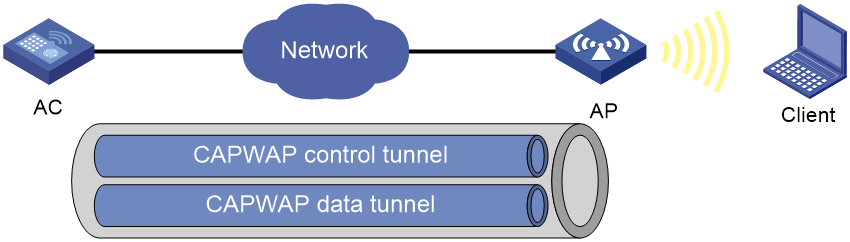
Control And Provisioning of Wireless Access Points (CAPWAP) defines how an AP communicates with an AC. It provides a generic encapsulation and transport mechanism between AP and AC. CAPWAP uses UDP and supports both IPv4 and IPv6.
As shown in Figure 1, an AC and an AP establish a data tunnel to forward data packets and a control tunnel to forward control packets.
AC discovery
After starting up with zero configurations, an AP automatically creates VLAN-interface 1 and enables the DHCP client, DHCPv6 client, and DNS features on the interface. Then it obtains its own IP address from the DHCP server and discovers ACs by using the following methods:
· Static IP address.
If AC IP addresses have been manually configured for the AP, the AP sends a unicast discovery request to each AC IP address to discover ACs.
· DHCP options.
The AP obtains AC IPv4 addresses from Option 138, Option 43, and IPv6 addresses from Option 52 sent from the DHCP server. It uses these addresses in descending order.
· DNS.
a. The AP obtains the domain name suffix from the DHCP server.
b. The AP adds the suffix to the host name.
c. The DNS server translates the domain name into IP addresses.
For more information about DNS, see Layer 3—IP Services Configuration Guide.
· Broadcast.
The AP broadcasts discovery requests to IP address 255.255.255.255 to discover ACs.
· IPv4 multicast:
The AP sends multicast discovery requests to IPv4 address 224.0.1.140 to discover ACs.
· IPv6 multicast.
The AP sends multicast discovery requests to IPv6 address FF0E::18C to discover ACs.
The methods of static IP address, DHCPv4 options, broadcast/IPv4 multicast, IPv4 DNS, IPv6 multicast, DHCPv6 option, and IPv6 DNS are used in descending order.
The AP does not stop AC discovery until it establishes a CAPWAP tunnel with one of the discovered ACs.
DHCP options
Option 43
Option 43 can be configured only in hexadecimal format, case insensitive. It contains the PXE server address sub-option and ACS parameter sub-option.
· PXE server address sub-option.
¡ If you specify one AC IPv4 address, for example, 2.2.2.2, you must specify option 43 hex 800700000102020202 in DHCP address pool view of the DHCP server.
- 80—Fixed value, 1 byte long.
- 07—Length of the subsequent fields. In this example, the subsequent fields are 7 byte long.
- 0000—Fixed value.
- 01—Number of AC IPv4 addresses. In this example, one IPv4 address is specified.
- 02020202—AC IPv4 address in hexadecimal format. You can specify a maximum of 16 IPv4 addresses, and spaces are not allowed between the IPv4 addresses.
¡ If you specify two AC IPv4 addresses, for example, 6.6.6.2 and 6.6.6.3, you must specify option 43 hex 800b0000020606060206060603 in DHCP address pool view of the DHCP server.
· ACS parameter sub-option.
¡ If you specify one AC IPv4 address, for example, 2.2.2.2, you must specify option 43 hex 010402020202 in DHCP address pool view of the DHCP server.
- 01—Fixed value, 1 byte long.
- 04—Length of the subsequent fields. In this example, the subsequent fields are 4 byte long.
- 02020202—AC IPv4 address in hexadecimal format. You can specify a maximum of 16 IPv4 addresses, and spaces are not allowed between the IPv4 addresses.
¡ If you specify two AC IPv4 addresses, for example, 6.6.6.2 and 6.6.6.3, you must specify option 43 hex 01080606060206060603 in DHCP address pool view of the DHCP server.
Option 138
Option 138 can be configured in hexadecimal and IP formats. In hexadecimal format, Option 138 contains the PXE server address sub-option and ACS parameter sub-option. The fields for the sub-options in hexadecimal format are the same as those for Option 43.
· If you specify one AC IPv4 address, for example, 192.168.0.100, you must specify option 138 ip-address 192.168.0.100 in DHCP address pool view of the DHCP server.
You can specify a maximum of 8 IPv4 addresses, and you must separate them with spaces.
· If you specify two AC IPv4 addresses, for example, 6.6.6.2 and 6.6.6.3, you must specify option 138 ip-address 6.6.6.2 6.6.6.3 in DHCP address pool view of the DHCP server.
Option 52
Option 52 can be configured only in hexadecimal format, case insensitive.
· If you specify one AC IPv6 address, for example, 3138:101::62, you must specify option 52 hex 31380101000000000000000000000062 in DHCP address pool view of the DHCP server.
The IPv6 address must contain 32 bytes. You can specify a maximum of 8 IPv6 addresses, and you must separate them with spaces.
· If you specify two AC IPv6 addresses, for example, 3138:101::62 and 3138:101::72, you must specify option 52 hex 3138010100000000000000000000006231380101000000000000000000000072 in DHCP address pool view of the DHCP server.
CAPWAP tunnel establishment
Figure 2 Establishing a CAPWAP tunnel
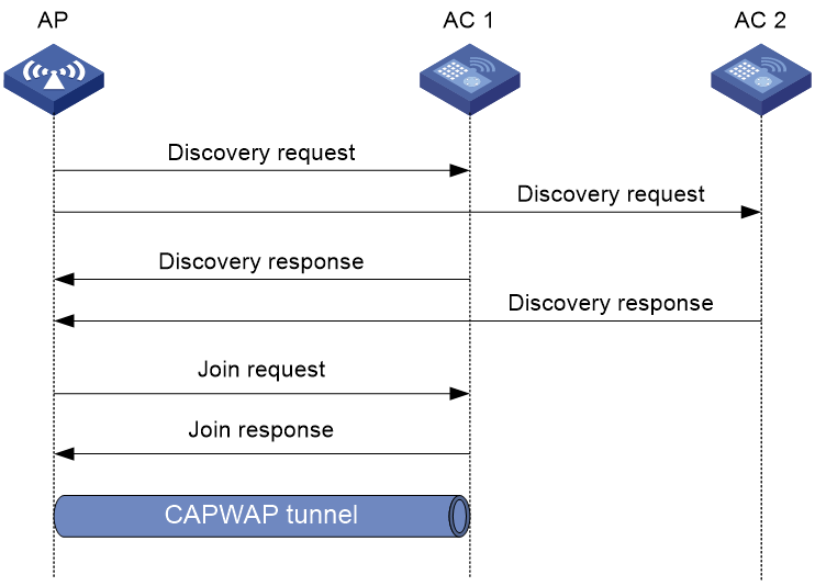
As shown in Figure 2, the AP and an AC establish a CAPWAP tunnel by using the following procedure:
1. The AP sends a discovery request to each AC to discover ACs.
2. Upon receiving a discovery request, an AC determines whether to send a discovery response by performing the following steps:
a. Identifies whether the discovery request is a unicast packet.
- Unicast packet—The AC proceeds to step b.
- Broadcast or multicast packet—The AC proceeds to step b if it is disabled with the feature of responding only to unicast discovery requests. If this feature is enabled, the AC does not send a discovery response.
- If manual AP configuration exists, the AC sends a discovery response to the AP. The discovery response contains information about whether the AC has the manual configuration for the AP, the AP connection priority, and the AC's load status.
- If no manual AP configuration exists, the AC proceeds to step c.
c. Identifies whether auto AP is enabled.
- If auto AP is enabled, the AC sends a discovery response to the AP. The discovery response contains the enabling status of auto AP, AP connection priority, and AC's load information.
- If auto AP is disabled, the AP does not send a discovery response.
3. Upon receiving the discovery responses, the AP selects the optimal AC in descending order.
¡ AC that saves information about the AP.
¡ AC where the auto AP feature is enabled.
¡ AC with higher AP connection priority.
¡ AC with the lighter load.
¡ AC that is the earliest to respond.
4. The AP sends a join request to the optimal AC.
5. After receiving the join request, the AC examines the information in the request to determine whether to provide access services to the AP and sends a join response.
6. The AP examines the result code in the response upon receiving the join response:
¡ If the result code represents failure, the AP does not establish a CAPWAP tunnel with the AC.
¡ If the result code represents success, the AP establishes a CAPWAP tunnel with the AC.
APDB
The Access Point Information Database (APDB) on an AC stores the following AP information:
· AP models.
· Hardware version and software version mappings.
· Information about radios supported by AP models:
¡ Number of radios.
¡ Radio type.
¡ Valid region code.
¡ Valid antenna type.
¡ Maximum transmission power.
The AC can establish a CAPWAP tunnel with an AP only when the APDB contains the corresponding AP model information.
You can use the system script and user scripts to manage data in the APDB. The system script is released with the AC software version, and it is automatically loaded each time the AC starts. If you need to add new AP models, upgrade the AC software version (see Fundamentals Configuration Guide) or create a user script and load it on the AC (see "Loading an APDB user script").
Protocols and standards
· RFC 5415, Control And Provisioning of Wireless Access Points (CAPWAP) Protocol Specification
Restrictions and guidelines: AP management configuration
You can configure APs by using the following methods:
· Configure APs one by one in AP view.
· Assign APs to an AP group and configure the AP group in AP group view.
· Configure all APs in global configuration view.
For an AP, the settings made in these views for the same parameter take effect in descending order of AP view, AP group view, and global configuration view.
As a best practice, configure APs in AP group view for large scale network deployment.
AP management tasks at a glance
To configure AP management, perform the following tasks:
1. Configuring CAPWAP tunnel establishment
Choose one of the tasks of creating a manual AP and managing auto APs.
¡ (Optional.) Setting the discovery-response timeout timer
¡ (Optional.) Setting the AP connection priority for the AC
¡ (Optional.) Enabling the AC to respond only to unicast discovery requests
¡ (Optional.) Configuring AC rediscovery
¡ (Optional.) Enabling an AP to prefer discovering ACs by IPv6 address
2. (Optional.) Configuring an AP group
3. (Optional.) Upgrading APs' software
4. (Optional.) Configuring remote configuration synchronization
5. (Optional.) Configuring DHCP snooping
6. (Optional.) Configuring a CAPWAP tunnel
¡ Configuring CAPWAP tunnel encryption
¡ Configuring CAPWAP tunnel latency detection
¡ Setting the control tunnel keepalive timer for an AP
¡ Setting the data tunnel keepalive interval for an AP
¡ Setting the maximum fragment size for CAPWAP packets
¡ Setting the TCP MSS for CAPWAP tunnels
7. (Optional.) Configuring region code settings
¡ Including or excluding region codes in beacon frames and probe responses
8. (Optional.) Configuring AC request retransmission
9. (Optional.) Preprovisioning APs
10. (Optional.) Configuring SNMP notifications
11. (Optional.) Maintaining APs
¡ Managing the file system of an AP
¡ Setting the statistics report interval
¡ Configuring auto loading of preprovisioned settings
¡ Deploying a configuration file to an AP
¡ Configuring APs to report gateway information to the AC
¡ Enabling bandwidth usage logging for AP interfaces
12. (Optional.) Configuring advanced features for AP management
¡ Configuring automatic AC association for fat APs and cloud-managed APs
¡ Configuring a fat AP or cloud-managed AP to operate in fit mode
¡ Switching the operating mode for a fit AP
¡ Enabling 5 GHz radio virtualization
13. (Optional.) Configuring AP power management
¡ Configuring the default input power level
¡ Enabling or disabling USB interfaces for APs
¡ Enabling or disabling PoE for PIs
14. (Optional.) Maintaining ACs
¡ Configuring a description for the AC
¡ Enabling time zone synchronization
¡ Enabling service anomaly detection
15. (Optional.) Configuring an AP monitor group
Configuring CAPWAP tunnel establishment
Prerequisites for configuring CAPWAP tunnel establishment
Before you manage APs, complete the following tasks:
· Create a DHCP address pool on the DHCP server to assign IP addresses to APs.
· If DHCP options are used for AC discovery, configure Option 138, Option 43, or Option 52 in the specified DHCP address pool on the DHCP server.
· If DNS is used for AC discovery, configure the IP address of the DNS server and the AC domain name suffix in the specified DHCP address pool on the DHCP server. Then configure the mapping between the domain name and the AC IP address on the DNS server.
· Make sure the APs and the AC can reach each other.
For more information about DHCP and DNS, see Network Connectivity Configuration Guide.
Creating a manual AP
About this task
You can create a manual AP on the AC based on the AP model, serial ID, and MAC address of the AP you are using. An AP prefers to establish a CAPWAP tunnel with an AC that saves the manual AP configuration.
Restrictions and guidelines
After you create a fat AP or cloud-managed AP, you can configure only software upgrade and operating mode switching commands in AP view or AP group view for that AP.
Procedure
1. Enter system view.
system-view
2. Create a manual AP and enter its view.
¡ Create a physical AP.
wlan ap ap-name [ model model-name ]
¡ Create a virtual AP.
wlan virtual-ap ap-name [ model model-name ]
You must specify the model name when you create an AP.
3. Specify the serial ID or the MAC address for the AP.
¡ Specify the serial ID for the AP.
serial-id serial-id
¡ Specify the MAC address for the AP.
mac-address mac-address
By default, neither the serial ID nor the MAC address is specified for an AP.
4. (Optional.) Configure a description for the AP.
description text
By default, an AP does not have a description.
Managing auto APs
About this task
The auto AP feature enables APs to connect to an AC without manual AP configuration. This feature simplifies configuration when you deploy a large number of APs in a WLAN.
For security purposes, you can use the following methods to authenticate auto APs:
· Local authentication.
The AC authenticates an auto AP by serial ID or MAC address. When an auto AP initiates a connection request, the AC uses an ACL specified by the wlan ap-authentication acl command to match the auto AP. Assume that the AC authenticates the auto AP by serial ID.
¡ If the serial ID matches a permit rule, the auto AP passes the authentication and associates with the AC.
¡ If the serial ID matches a deny rule, the auto AP fails the authentication and cannot associate with the AC.
¡ If the serial ID does not match a rule, the auto AP is determined as an unauthenticated auto AP. An unauthenticated auto AP can associate with the AC but cannot provide wireless services.
· Remote authentication.
Remote authentication is used for authenticating unauthenticated auto APs. The AC uses the serial ID or MAC address of an unauthenticated auto AP as the username and password and sends them to the authentication server for authentication. If the authentication succeeds, the AC accepts the AP. If it does not succeed, the AC rejects the AP.
· Manual authentication.
Manual authentication is used for authenticating unauthenticated auto APs.
The AC determines whether to accept an unauthenticated auto AP depending on the manual authentication configuration.
Restrictions and guidelines
To prevent illegal APs from associating with the AC, disable the auto AP feature after all required APs are associated with the AC.
You must convert auto APs to manual APs after they come online because of the following reasons:
· Auto APs can re-associate with the AC upon an AC reboot or CAPWAP tunnel termination only when they are converted to manual APs.
· You can individually configure auto APs only when they are converted to manual APs.
Tasks at a glance
To configure auto APs, perform the following tasks:
1. Enabling the auto AP feature
2. (Optional.) Converting auto APs to manual APs
3. (Optional.) Configuring auto AP authentication
Choose one of the following tasks:
¡ Configuring auto AP local authentication
¡ Configuring auto AP remote authentication
¡ Manually authenticating unauthenticated auto APs
4. (Optional.) Disabling unauthenticated auto APs from associating with the AC
5. (Optional.) Restarting unauthenticated auto APs
Prerequisites
Before you configure remote authentication for auto APs, specify an authentication domain and AAA scheme on the AC and create user accounts on the RADIUS server. For information about authentication domain and AAA scheme configuration, see AAA in User Access and Authentication Configuration Guide.
Enabling the auto AP feature
1. Enter system view.
system-view
2. Enable the auto AP feature.
wlan auto-ap enable
By default, the auto AP feature is disabled.
Converting auto APs to manual APs
1. Enter system view.
system-view
2. Convert auto APs to manual APs. Choose the options to configure as needed:
¡ Convert online auto APs to manual APs.
wlan auto-ap persistent { all | name auto-ap-name [ new-ap-name ] }
¡ Enable the auto AP conversion feature.
wlan auto-persistent enable
By default, the auto AP conversion feature is disabled.
The wlan auto-persistent enable command does not take effect on auto APs that are already online.
Configuring auto AP local authentication
1. Enter system view.
system-view
2. Specify an authentication method.
wlan ap-authentication method { mac-address | serial-id }
By default, the AC authenticates auto APs by MAC address.
3. Create a WLAN AP ACL.
acl wlan ap { acl-number | name acl-name }
For more information about this command, see ACL in Security Command Reference.
4. Return to system view.
quit
5. Specify an ACL for authenticating auto APs.
wlan ap-authentication acl acl-number
By default, no ACL is specified for authenticating auto APs.
6. Create ACL rules for the WLAN AP ACL. Choose the options to configure as needed:
¡ Execute the following commands in sequence to manually create a rule:
acl wlan ap { acl-number | name acl-name }
rule [ rule-id ] { deny | permit } [ mac mac-address mac-mask ] [ serial-id serial-id ]
quit
¡ Import an auto AP authentication file to generate ACL rules.
wlan ap-authentication import file-name
Use either method or both methods according to actual network requirements.
7. Enable auto AP authentication.
wlan ap-authentication enable
By default, auto AP authentication is disabled.
Configuring auto AP remote authentication
1. Enter system view.
system-view
2. Specify an authentication domain for unauthenticated auto APs.
wlan ap-authentication domain domain-name
By default, no authentication domain is specified for unauthenticated auto APs.
Manually authenticating unauthenticated auto APs
1. Enter system view.
system-view
2. Manually authenticate unauthenticated auto APs.
wlan ap-authentication { accept | reject } ap-unauthenticated { all | name ap-name }
By default, manual authentication is not configured for unauthenticated auto APs.
Disabling unauthenticated auto APs from associating with the AC
1. Enter system view.
system-view
2. Disable unauthenticated auto APs from associating with the AC.
undo wlan ap-authentication permit-unauthenticated
By default, unauthenticated auto APs can associate with the AC but cannot provide wireless services.
This feature reduces waste of system resources.
Restarting unauthenticated auto APs
To restart unauthenticated auto APs, execute the following command in user view:
reset wlan ap unauthenticated
The auto APs will be reauthenticated after being restarted.
Setting the discovery-response timeout timer
About this task
The discovery-response timeout timer specifies the timeout time for an AP to wait for another discovery response. Whenever an AP receives a discovery response packet, the discovery-response timeout timer is created or refreshed. When the timeout timer expires, the AP sends a join request to the optimal AC.
Restrictions and guidelines
If the network condition is poor, set a larger discovery-response timeout timer.
Procedure
1. Enter system view.
system-view
2. Enter AP view or AP group view.
¡ Enter AP view.
wlan ap ap-name
¡ Enter AP group view.
wlan ap-group group-name
3. Set the discovery-response timeout timer.
discovery-response wait-time seconds
By default:
¡ In AP view, an AP uses the configuration in AP group view.
¡ In AP group view, the discovery-response timeout timer is 2 seconds.
Setting the AP connection priority for the AC
1. Enter system view.
system-view
2. Enter AP view or AP group view.
¡ Enter AP view.
wlan ap ap-name
¡ Enter AP group view.
wlan ap-group group-name
3. Set the AP connection priority for the AC.
priority priority
By default:
¡ In AP view, an AP uses the configuration in AP group view.
¡ In AP group view, the AP connection priority is 4.
Enabling the AC to respond only to unicast discovery requests
About this task
An AP can send unicast, multicast, and broadcast discovery requests to discover ACs. This feature enables an AC to respond only to unicast discovery requests.
Procedure
1. Enter system view.
system-view
2. Enable the AC to respond only to unicast discovery requests.
wlan capwap discovery-policy unicast
By default, the AC can respond to unicast, multicast, and broadcast discovery requests.
Configuring AC rediscovery
About this task
An AC enabled with AC rediscovery will add the CAPWAP Control IP Address message element to the discovery responses sent to APs. Upon receiving such a discovery response, an AP establishes a CAPWAP tunnel by using the following procedure:
1. Examines whether a discovery request has been sent to each IP address specified in the CAPWAP Control IP Address message element.
2. Performs either of the following operations:
¡ Sends a join request to the specified IP address representing the optimal AC for CAPWAP establishment if discovery requests have been sent.
¡ Sends a discovery request to each specified IP address to initiate a new AC discovery process if no discovery requests have been sent.
An AC disabled with AC rediscovery does not add the CAPWAP Control IP Address message element in discovery responses sent to APs. APs that receive the discovery responses will send join requests to the source IP address of the discovery responses to establish CAPWAP tunnels with the AC.
AC rediscovery applies to the following scenarios:
· CMCC wireless networks where the CAPWAP Control IP Address message element is required in discovery responses from the AC.
· AC hierarchical networks where the central AC uses the CAPWAP Control IP Address message element to assign local ACs' IP addresses to APs. For information about AC hierarchy, see configuring AC hierarchy in WLAN Advanced Features Configuration Guide.
Procedure
1. Enter system view.
system-view
2. Enter AP view, AP group view, or global configuration view.
¡ Enter AP view.
wlan ap ap-name
¡ Enter AP group view.
wlan ap-group group-name
¡ Enter global configuration view.
wlan global-configuration
3. Configure AC rediscovery.
control-address { disable | enable }
By default:
¡ In AP view, an AP uses the configuration in AP group view. If no configuration exists in AP group view, the AP uses the configuration in global configuration view.
¡ In AP group view, an AP uses the configuration in global configuration view.
¡ In global configuration view, AC rediscovery is disabled.
4. Specify the IP address to be added in the CAPWAP Control IP Address message element.
control-address { ip ipv4-address | ipv6 ipv6-address }
By default:
¡ In AP view, an AP uses the configuration in AP group view. If no configuration exists in AP group view, the AP uses the configuration in global configuration view.
¡ In AP group view, an AP uses the configuration in global configuration view.
¡ In global configuration view, the IP address in the element is one of the following:
- On a non-AC hierarchical network—AC's IP address.
- On an AC hierarchical network—IP address of the lightest loaded local AC for a central AC and IP address of the local AC for a local AC.
You can specify a maximum of three IPv4 or IPv6 addresses to be added in the CAPWAP Control IP Address message element.
Enabling an AP to prefer discovering ACs by IPv6 address
About this task
This feature enables an AP to discover ACs by using static IP addresses, IPv6 multicast, DHCPv6 option, IPv6 DNS, DHCPv4 options, broadcast/IPv4 multicast, and IPv4 DNS successively. If the AP connects to an AC successfully by using a discovered IP address, it stops AC discovery.
Procedure
1. Enter system view.
system-view
2. Enter AP view or AP group view.
¡ Enter AP view.
wlan ap ap-name
¡ Enter AP group view.
wlan ap-group group-name
3. Enter AP or AP group provision view.
provision
4. Enable the AP to prefer discovering ACs by IPv6 address.
ac discovery policy ipv6
By default:
¡ In AP view, an AP uses the configuration in AP group view.
¡ In AP group view, an AP prefers to discover ACs by IPv4 address.
Configuring an AP group
About this task
This feature enables you to configure multiple APs in a batch to reduce configuration workload.
APs in an AP group use the configuration of the group. By default, all physical APs belong to system-defined AP group default-group, and all virtual APs belong to the system-defined virtual AP group default-vitualapgroup. The system-defined AP group cannot be deleted.
You can configure AP grouping rules by AP name, serial ID, MAC address, and IP address to add APs to the specified AP group. Priorities of these grouping rules are in descending order. If an AP does not match any grouping rules, it is added to the default AP group.
Restrictions and guidelines
An AP can be added to only one AP group.
You cannot delete an AP group that contains an AP. An AP group that has grouping rules but does not contain any APs can be deleted.
When you configure an AP grouping rule, follow these restrictions and guidelines:
· You cannot create the same grouping rule for different AP groups. If you do so, the most recent configuration takes effect.
· You cannot create grouping rules for the default AP group.
· AP grouping rules by IPv4 or IPv6 addresses for an AP group or for different AP groups cannot overlap with each other.
· An AP group supports a maximum of 32 AP grouping rules by IPv4 or IPv6 addresses.
Procedure
1. Enter system view.
system-view
2. Create an AP group and enter its view.
¡ Create a physical AP group.
wlan ap-group group-name
By default, system-defined physical AP group default-group exists.
¡ Create a virtual AP group.
wlan virtual-ap-group group-name
By default, system-defined virtual AP group default-vitualapgroup exists.
3. (Optional.) Configure a description for the AP group.
description text
By default, an AP group does not have a description.
4. Create an AP grouping rule. Choose the options to configure as needed:
¡ Create an AP grouping rule by AP names.
ap ap-name-list
¡ Create an AP grouping rule by serial IDs.
serial-id serial-id
¡ Create an AP grouping rule by MAC addresses.
mac-address mac-address
¡ Create an AP grouping rule by IPv4 addresses.
if-match ip ip-address { mask-length | mask }
¡ Create an AP grouping rule by IPv6 addresses.
if-match ipv6 { ipv6-address prefix-length | ipv6-address/prefix-length }
5. Return to system view.
quit
6. (Optional.) Create an AP regrouping rule.
wlan re-group { ap ap-name | ap-group old-group-name | mac-address mac-address | serial-id serial-id } group-name
Upgrading APs' software
About software upgrade
With software upgrade enabled, the AC examines the AP software version while establishing a CAPWAP tunnel with an AP. If this feature is disabled, the AC does not examine the software version of the AP and directly establishes a CAPWAP tunnel with the AP.
Software upgrade for an AP proceeds as follows:
1. The AP reports the software version and AP model information to the AC.
2. The AC examines the received AP software version.
¡ If a match is found, the AC establishes a CAPWAP tunnel with the AP.
¡ If no match is found, the AC sends a message that notifies the AP of the AP software version inconsistency.
3. Upon receiving the inconsistency message, the AP requests a software version from the AC.
4. The AC assigns the software version to the AP after receiving the request.
5. The AP upgrades the software version, restarts, and establishes a CAPWAP tunnel with the AC.
Configuring software upgrade
1. Enter system view.
system-view
2. Enter AP view/AP group view/virtual AP view/virtual AP group view/global configuration view.
¡ Enter AP view.
wlan ap ap-name
¡ Enter AP group view.
wlan ap-group group-name
¡ Enter virtual AP view.
wlan virtual-ap ap-name
¡ Enter virtual AP group view.
wlan virtual-ap-group group-name
¡ Enter global configuration view.
wlan global-configuration
3. Configure software upgrade.
firmware-upgrade { disable | enable }
By default:
¡ In AP view, an AP uses the configuration in AP group view. If no software upgrade configuration exists in AP group view, the AP uses the configuration in global configuration view.
¡ In AP group view, an AP uses the configuration in global configuration view.
¡ In virtual AP view, a virtual AP uses the configuration in virtual AP group view. If no software upgrade configuration exists in virtual AP group view, the virtual AP uses the configuration in global configuration view.
¡ In virtual AP group view, a virtual AP uses the configuration in global configuration view.
¡ In global configuration view, the software upgrade feature is enabled.
Configuring the mapping between a software version and a hardware version of an AP model
About this task
Perform this task to configure the mapping between a software version and a hardware version of an AP model for software upgrade.
For fit APs, perform this task only when the AP software version for an AP model stored in the APDB is inconsistent with the software version you expect for the AP model. To display the AP software version for each AP model in the APDB, use the display wlan ap-model command.
For cloud-managed APs and fat APs, perform this task only when you are to perform software upgrade for the APs. You must save the AP software version to upgrade to the apimage directory of the AC, and make sure the software version is the same as the software version to specify in this task.
Restrictions and guidelines
To avoid CAPWAP tunnel establishment failure, use this feature under the guidance of H3C Support.
Procedure
1. Enter system view.
system-view
2. Configure the mapping between a software version and a hardware version of an AP model.
wlan apdb [ fatap | oasisap ] model-name hardware-version software-version
By default:
¡ For fat APs, no software version and hardware version mapping is specified.
¡ For cloud-managed APs, no software version and hardware version mapping is specified.
¡ For fit APs, the software version for a hardware version of an AP model is the software version that is stored in APDB user scripts.
If you do not specify the fatap and oasisap keywords, this command specifies the software version and hardware version mapping for fit APs.
Specifying the preferred location for the AC to obtain an AP image file
About this task
The AC assigns an AP image file to an AP if the AP requests a software version during CAPWAP tunnel establishment. You can specify the preferred location as the AC's RAM or local folder for the AC to obtain an AP image file. If the AC cannot obtain an AP image file from the preferred location, it obtains an AP image file from the other location. If no AP image file exists, the AC fails to obtain an image file and cannot assign a software version to the AP.
Restrictions and guidelines
The AC can assign only .ipe AP image files to APs.
If you specify the local folder, make sure the AC uses a CF or flash card as the default file system and the AP image file is stored in the root directory of the file system on the AC.
Procedure
1. Enter system view.
system-view
2. Specify the preferred location for the AC to obtain an AP image file.
wlan image-load filepath { local | ram }
By default, the AC prefers the AP image file stored in the RAM when assigning a software version to an AP.
Deploying an image file to online APs
About this task
This feature enables you to upgrade the image of all the online APs. For the upgrade to take effect, reboot the APs after upgrade.
Procedure
1. Enter system view.
system-view
2. Deploy an image file to all the online APs.
wlan ap-image-deploy { all | ap-group group-name | name ap-name }
Configuring remote configuration synchronization
|
|
NOTE: Support for this feature depends on the AP model. |
About remote configuration synchronization
To update APs' configuration file or configure features that require a configuration file, you can use the map-configuration command to deploy a configuration file to APs. However, you must write related commands to the configuration file before deployment. This is time-consuming and is not applicable to a network with a large number of APs to deploy.
This feature enables the AC to directly synchronize AP settings such as VLAN, link aggregation, and port isolation changes to online APs.
Tasks at a glance
To configure remote configuration synchronization, perform the following tasks:
1. Shutting down or bringing up Ethernet interfaces on a fit AP
2. Creating a Layer 2 aggregate interface
3. Assigning an interface to a Layer 2 aggregation group
5. Configuring basic VLAN settings
6. Assigning a port to a VLAN
¡ Assigning an access port to a VLAN
¡ Assigning a trunk port to VLANs
¡ Assigning a hybrid port to VLANs
¡ Setting the trusted packet priority type
7. Synchronizing settings to online APs
Shutting down or bringing up Ethernet interfaces on a fit AP
About this task
To avoid unauthorized access to a fit AP from an unused interface on the AP, you can perform this task to shut down unused Ethernet interfaces on the AP.
Restrictions and guidelines
This command does not take effect on the uplink interface of a fit AP that connects the AP to the AC.
Do not shut down an interface when it is being removed from an aggregation group.
The interface-management shutdown command does not take effect on member interfaces of an aggregation group.
Procedure
1. Enter system view.
system-view
2. Enter AP view or an AP group's AP model view.
¡ Enter AP view.
wlan ap ap-name
¡ Execute the following commands in sequence to enter an AP group's AP model view:
wlan ap-group group-name
ap-model ap-model
3. Enter Ethernet interface view.
¡ Enter Eth interface view.
ethernet interface-number
¡ Enter GigabitEthernet interface view.
gigabitethernet interface-number
¡ Enter 2.5G Ethernet interface view.
smartrate-ethernet interface-number
¡ Enter 10-GE interface view.
ten-gigabitethernet interface-number
¡ Enter Layer 2 aggregate interface view.
bridge-aggregation interface-number
4. Bring up or shut down the interface on the fit AP.
interface-management { bringup | shutdown }
By default, in an AP's Ethernet interface view, the AP uses the configuration in an AP group's Ethernet interface view. In an AP group's Ethernet interface view, the interface is up.
Creating a Layer 2 aggregate interface
Restrictions and guidelines
When you create a Layer 2 aggregate interface, the system automatically creates a Layer 2 aggregation group with the same number. The aggregation group operates in static aggregation mode by default.
Aggregation mode change might cause Selected member ports to become Unselected. When you change the aggregation mode, make sure you understand the impact of the change on services.
The configuration will be synchronized to all online APs after remote configuration synchronization is activated.
Procedure
1. Enter system view.
system-view
2. Enter AP view or an AP group's AP model view.
¡ Enter AP view.
wlan ap ap-name
¡ Execute the following commands in sequence to enter an AP group's AP model view:
wlan ap-group group-name
ap-model ap-model
3. Create a Layer 2 aggregate interface and enter its view.
bridge-aggregation interface-number
4. Set the aggregation mode of an aggregation group and set the LACP state.
link-aggregation mode { dynamic | static }
By default:
¡ In an AP's Layer 2 aggregate interface view, the AP uses the configuration in an AP group's Layer 2 aggregate interface view.
¡ In an AP group's Layer 2 aggregate interface view, an aggregation group operates in static aggregation mode.
Assigning an interface to a Layer 2 aggregation group
Restrictions and guidelines
A Layer 2 Ethernet interface can be assigned only to a Layer 2 aggregation group and an Ethernet interface can belong to only one aggregation group.
After joining an aggregation group, an interface inherits the settings configured for the group.
Before you perform this task, make sure the specified aggregation group already exists and the AP supports Layer 2 aggregate interfaces.
The configuration will be synchronized to all online APs after remote configuration synchronization is activated.
Procedure
1. Enter system view.
system-view
2. Enter AP view or an AP group's AP model view.
¡ Enter AP view.
wlan ap ap-name
¡ Execute the following commands in sequence to enter an AP group's AP model view:
wlan ap-group group-name
ap-model ap-model
3. Enter Ethernet interface view.
¡ Enter Eth interface view.
ethernet interface-number
¡ Enter GigabitEthernet interface view.
gigabitethernet interface-number
¡ Enter 2.5G Ethernet interface view.
smartrate-ethernet interface-number
¡ Enter 10-GE interface view.
ten-gigabitethernet interface-number
4. Assign an interface to an aggregation group.
port link-aggregation group group-id
By default, in an AP's Layer 2 Ethernet interface view, the AP uses the configuration in an AP group's Layer 2 Ethernet interface view. In an AP group's Layer 2 Ethernet interface view, an interface does not belong to an aggregation group.
Configuring port isolation
Restrictions and guidelines
The configuration in Ethernet interface view applies only to the interface.
The configuration in Layer 2 aggregate interface view applies to the Layer 2 aggregate interface and its aggregation member ports. If the device fails to apply the configuration to the aggregate interface, it does not assign any aggregation member port to the isolation group. If the failure occurs on an aggregation member port, the device skips the port and continues to assign other aggregation member ports to the isolation group.
The configuration will be synchronized to all online APs after remote configuration synchronization is activated.
Procedure
1. Enter system view.
system-view
2. Enter AP view or an AP group's AP model view.
¡ Enter AP view.
wlan ap ap-name
¡ Execute the following commands in sequence to enter an AP group's AP model view:
wlan ap-group group-name
ap-model ap-model
3. Enter Ethernet interface view.
¡ Enter Eth interface view.
ethernet interface-number
¡ Enter GigabitEthernet interface view.
gigabitethernet interface-number
¡ Enter 2.5G Ethernet interface view.
smartrate-ethernet interface-number
¡ Enter 10-GE interface view.
ten-gigabitethernet interface-number
¡ Enter Layer 2 aggregate interface view.
bridge-aggregation interface-number
4. Configure port isolation.
port-isolate { enable | disable }
By default, in an AP's Ethernet interface view, a port uses the configuration in an AP group's Ethernet interface view. In an AP group's Ethernet interface view, port isolation is enabled.
Configuring basic VLAN settings
Restrictions and guidelines
You cannot create or delete VLAN 1 (the default VLAN) or reserved VLANs.
The configuration will be synchronized to all online APs after remote configuration synchronization is activated.
Procedure
1. Enter system view.
system-view
2. Enter AP view or AP group view.
¡ Enter AP view.
wlan ap ap-name
¡ Enter AP group view.
wlan ap-group group-name
3. (Optional.) Create a VLAN and enter its view, or create a list of VLANs.
vlan { vlan-id1 [ to vlan-id2 ] }
By default, only VLAN 1 (the system default VLAN) exists.
4. Enter VLAN view.
vlan vlan-id
To configure a VLAN after bulk VLAN creation, perform this step.
Assigning an access port to a VLAN
Restrictions and guidelines
The configuration will be synchronized to all online APs after remote configuration synchronization is activated.
Procedure
1. Enter system view.
system-view
2. Enter AP view or an AP group's AP model view.
¡ Enter AP view.
wlan ap ap-name
¡ Execute the following commands in sequence to enter an AP group's AP model view:
wlan ap-group group-name
ap-model ap-model
3. Enter Ethernet interface view.
¡ Enter Eth interface view.
ethernet interface-number
¡ Enter GigabitEthernet interface view.
gigabitethernet interface-number
¡ Enter 2.5G Ethernet interface view.
smartrate-ethernet interface-number
¡ Enter 10-GE interface view.
ten-gigabitethernet interface-number
¡ Enter Layer 2 aggregate interface view.
bridge-aggregation interface-number
Use a command according to the AP model and network requirements.
4. Set the link type to access.
port link-type access
By default, in an AP's Ethernet interface view, a port uses the configuration in an AP group's Ethernet interface view. In an AP group's Ethernet interface view, all ports are access ports.
5. Assign the access port to a VLAN.
port access vlan vlan-id
By default, in an AP's Ethernet interface view, an access port uses the configuration in an AP group's Ethernet interface view. In an AP group's Ethernet interface view, an access port belongs to VLAN 1.
Make sure the VLAN has been created.
Assigning a trunk port to VLANs
Restrictions and guidelines
A trunk port can allow multiple VLANs. If you execute this command multiple times on a trunk port, the trunk port allows all the specified VLANs.
On a trunk port, packets from only the PVID can pass through untagged.
To prevent unauthorized VLAN users from accessing restricted resources through the port, use the port trunk permit vlan all command with caution.
The configuration will be synchronized to all online APs after remote configuration synchronization is activated.
Procedure
1. Enter system view.
system-view
2. Enter AP view or an AP group's AP model view.
¡ Enter AP view.
wlan ap ap-name
¡ Execute the following commands in sequence to enter an AP group's AP model view:
wlan ap-group group-name
ap-model ap-model
3. Enter Ethernet interface view.
¡ Enter Eth interface view.
gigabitethernet interface-number
¡ Enter GigabitEthernet interface view.
gigabitethernet interface-number
¡ Enter 2.5G Ethernet interface view.
smartrate-ethernet interface-number
¡ Enter 10-GE interface view.
ten-gigabitethernet interface-number
¡ Enter Layer 2 aggregate interface view.
bridge-aggregation interface-number
Use a command according to the AP model and network requirements.
4. Set the link type to trunk.
port link-type trunk
By default, in an AP's Ethernet interface view, a port uses the configuration in an AP group's Ethernet interface view. In an AP group's Ethernet interface view, all ports are access ports.
5. Assign the trunk port to the specified VLANs.
port trunk permit vlan { vlan-id-list | all }
By default, in an AP's Ethernet interface view, a trunk port uses the configuration in an AP group's Ethernet interface view. In an AP group's Ethernet interface view, a trunk port does not permit packets from any VLAN to pass through.
6. (Optional.) Set the PVID for the trunk port.
port trunk pvid vlan vlan-id
By default, in an AP's Ethernet interface view, a trunk port uses the configuration in an AP group's Ethernet interface view. In an AP group's Ethernet interface view, the PVID of a trunk port is VLAN 1.
Assigning a hybrid port to VLANs
Restrictions and guidelines
You can use a nonexistent VLAN as the PVID of a hybrid port. When you delete the PVID of a hybrid port by using the undo vlan command, the PVID setting of the port does not change.
For correct packet transmission, set the same PVID for a hybrid port on an AP and the hybrid port on the switch connected to the AP.
To enable a hybrid port to transmit packets from its PVID, you must assign the hybrid port to the PVID by using the port hybrid vlan command.
The configuration will be synchronized to all online APs after remote configuration synchronization is activated.
Procedure
1. Enter system view.
system-view
2. Enter AP view or an AP group's AP model view.
¡ Enter AP view.
wlan ap ap-name
¡ Execute the following commands in sequence to enter an AP group's AP model view:
wlan ap-group group-name
ap-model ap-model
3. Enter Ethernet interface view.
¡ Enter Eth interface view.
ethernet interface-number
¡ Enter GigabitEthernet interface view.
gigabitethernet interface-number
¡ Enter 2.5G Ethernet interface view.
smartrate-ethernet interface-number
¡ Enter 10-GE interface view.
ten-gigabitethernet interface-number
¡ Enter Layer 2 aggregate interface view.
bridge-aggregation interface-number
Use a command according to the AP model and network requirements.
4. Set the link type to hybrid.
port link-type hybrid
By default, in an AP's Ethernet interface view, a port uses the configuration in an AP group's Ethernet interface view. In an AP group's Ethernet interface view, all ports are access ports.
5. Assign the hybrid port to the specified VLANs.
port hybrid vlan vlan-id-list { tagged | untagged }
By default, in an AP's Ethernet interface view, a hybrid port uses the configuration in an AP group's Ethernet interface view. In an AP group's Ethernet interface view, a hybrid port does not permit packets from any VLAN to pass through.
6. (Optional.) Set the PVID for the hybrid port.
port hybrid pvid vlan vlan-id
By default, in an AP's Ethernet interface view, a hybrid port uses the configuration in an AP group's Ethernet interface view. In an AP group's Ethernet interface view, the PVID of a hybrid port is the ID of the VLAN to which the port belongs when its link type is access.
Setting the trusted packet priority type
About this task
With a priority type and a port priority value specified for an interface, an AP assigns the priority of the specified type to all packets received on the interface.
The system supports the following trusted packet priority types:
· dot11e—Uses the 802.1e priority carried in packets for priority mapping.
· dscp—Uses the DSCP priority carried in packets for priority mapping.
Procedure
1. Enter system view.
system-view
2. Enter AP view or AP group's AP model view.
¡ Enter AP view.
wlan ap ap-name
¡ Enter AP group's AP model view.
wlan ap-group group-name
ap-model ap-model
3. Enter Ethernet interface view.
¡ Enter Eth interface view.
ethernet interface-number
¡ Enter GigabitEthernet interface view.
gigabitethernet interface-number
¡ Enter 2.5G Ethernet interface view.
smartrate-ethernet interface-number
¡ Enter 10-GE interface view.
Ten-gigabitethernet interface-number
¡ Enter Layer 2 aggregate interface view.
bridge-aggregation interface-number
Use a command according to the AP model and network requirements.
4. Set the trusted packet priority type.
qos trust { dot1p | dscp }
By default, in an AP's Ethernet interface view, the AP uses the configuration in AP group view. In an AP group's Ethernet interface view, no trusted packet priority type is set.
Setting the port priority
About this task
With a priority type and a port priority value specified for an interface, an AP assigns the priority of the specified type to all packets received on the interface.
Procedure
1. Enter system view.
system-view
2. Enter AP view or AP group's AP model view.
¡ Enter AP view.
wlan ap ap-name
¡ Enter AP group's AP model view.
wlan ap-group group-name
ap-model ap-model
3. Enter Ethernet interface view.
¡ Enter Eth interface view.
ethernet interface-number
¡ Enter GigabitEthernet interface view.
gigabitethernet interface-number
¡ Enter 2.5G Ethernet interface view.
smartrate-ethernet interface-number
¡ Enter 10-GE interface view.
Ten-gigabitethernet interface-number
¡ Enter Layer 2 aggregate interface view.
bridge-aggregation interface-number
Use a command according to the AP model and network requirements.
4. Set the port priority.
qos priority priority-value
By default, in an AP's Ethernet interface view, the AP uses the configuration in AP group view. In an AP group's Ethernet interface view, the port priority is 0.
Synchronizing settings to online APs
About this task
This feature enables the AC to directly synchronize AP settings such as VLAN, link aggregation, and port isolation changes to online APs.
Restrictions and guidelines
|
|
CAUTION: This feature clears all VLAN, link aggregation, and port settings (except for port isolation settings) on online APs and issues the settings on the AC to the APs. Please use it with caution. If any of these settings cannot be cleared, a configuration conflict has occurred on the AC. You must verify the settings on the AC. |
This feature takes effect only when both remote configuration assignment and remote configuration synchronization are configured. If only remote configuration assignment is configured, the AC assigns only VLAN settings to the specified AP or AP group.
With remote configuration assignment enabled, APs request VLAN, link aggregation, and port settings from the AC automatically after coming online.
Remote configuration synchronization takes effect only when remote configuration assignment is enabled.
As a best practice, do not use both remote configuration synchronization and the map-configuration command on the AC. If you must use both of them on the AC, make sure the VLAN, link aggregation, and port isolation settings in the configuration file to be deployed do not conflict with the settings on the AC.
Procedure
1. Enter system view.
system-view
2. Enter AP view or AP group view.
¡ Enter AP view.
wlan ap ap-name
¡ Enter AP group view.
wlan ap-group group-name
3. Enable remote configuration assignment.
remote-configuration enable
By default:
¡ In AP view, an AP uses the configuration in AP group view.
¡ In AP group view, remote configuration assignment is disabled.
4. Activate remote configuration synchronization.
remote-configuration synchronize
By default:
¡ In AP view, an AP uses the configuration in AP group view.
¡ In AP group view, remote configuration synchronization is not activated.
Configuring DHCP snooping
About DHCP snooping
DHCP snooping is a security feature for DHCP. DHCP snooping works between the DHCP client and DHCP server, or between the DHCP client and DHCP relay agent. It guarantees that DHCP clients obtain IP addresses from authorized DHCP servers. For more information about DHCP snooping, see DHCP snooping configuration in Network Connectivity Configuration Guide.
Tasks at a glance
To configure remote configuration synchronization, perform the following tasks:
1. Configuring basic DHCP snooping features
2. Configuring DHCP snooping support for Option 82
Configuring basic DHCP snooping features
1. Enter system view.
system-view
2. Enter AP view.
wlan ap ap-name
3. Enable DHCP snooping.
dhcp snooping enable
By default, DHCP snooping is disabled.
Configuring DHCP snooping support for Option 82
About this task
Option 82 is the relay agent option. It records the location information about the DHCP client. The administrator can use Option 82 to locate the DHCP client and further implement security control and accounting. For more information about Option 82, see DHCP snooping configuration in Network Connectivity Configuration Guide.
Procedure
1. Enter system view.
system-view
2. Enter AP view.
wlan ap ap-name
3. Enable DHCP snooping to support Option 82.
dhcp snooping information enable
By default, DHCP snooping does not support Option 82.
4. Configure the padding mode and padding format for the Circuit ID sub-option.
dhcp snooping information circuit-id { normal | wlan-private [ encoded ] } [ format { ascii | hex } ]
By default, the padding mode is normal and the padding format is hex for the Circuit ID sub-option.
5. Configure the padding mode and padding format for the Remote ID sub-option.
dhcp snooping information remote-id { normal [ format { ascii | hex } ] | string remote-id | none }
By default, the padding mode is normal and the padding format is hex for the Remote ID sub-option.
Configuring a CAPWAP tunnel
Configuring CAPWAP tunnel encryption
About this task
CAPWAP tunnel encryption uses the Datagram Transport Layer Security (DTLS) protocol to encrypt control and data packets transmitted over a CAPWAP tunnel.
When CAPWAP control tunnel encryption is enabled for an AP, the AC and the AP communicate as follows:
1. The AC sends a discovery response with the encryption flag to the AC.
2. The AP performs a DTLS handshake with the AC and then establishes a CAPWAP tunnel with the AC.
3. The AC and the AP encrypt control packets transmitted in the CAPWAP control tunnel after the DTLS handshake.
When CAPWAP data tunnel encryption is enabled for an AP, the AP exchanges encryption information including keys with the AC through the CAPWAP control tunnel upon receiving the first keepalive packet from the AC. After the exchange, the AC and the AP encrypt data packets transmitted in the CAPWAP data tunnel. Keepalive packets are not encrypted.
Restrictions and guidelines
After you enable CAPWAP control tunnel encryption, APs go offline and then come online again from the AC to re-establish CAPWAP tunnels.
CAPWAP control tunnel encryption requires a certificate. You can use the built-in certificate or specify a certificate for the AC. For the specified certificate to take effect, specify the certificate before enabling CAPWAP control tunnel encryption.
CAPWAP control tunnel encryption supports AP certificate verification to allow only APs with a matching certificate to come online. To use AP certificate verification, you must generate AP certificates, upload them to the AC, and execute the download file command to download the certificates to the corresponding APs. With the verification feature enabled, an AP can come online only when a certificate that uses the AP's MAC address as its CN exists on the AC.
Prerequisites
To use a non-built-in certificate, save the certificate, key, and CA certificate to the file system of the AC. These files can be in the .pem or .cer format.
Procedure
1. Enter system view.
system-view
2. Specify the certificate used for CAPWAP tunnel encryption.
wlan capwap encryption certificate cer-name key key-name ca ca-name
By default, the system uses the built-in certificate for CAPWAP tunnel encryption.
3. (Optional.) Enable AP certificate verification.
wlan ap-certificate verification
By default, AP certificate verification is disabled.
4. Enter AP view/AP group view/virtual AP view/virtual AP group view.
¡ Enter AP view.
wlan ap ap-name
¡ Enter AP group view.
wlan ap-group group-name
¡ Enter virtual AP view.
wlan virtual-ap ap-name
¡ Enter virtual AP group view.
wlan virtual-ap-group group-name
5. Configure CAPWAP control tunnel encryption.
tunnel encryption { disable | enable }
By default:
¡ In AP view, an AP uses the configuration in AP group view.
¡ In AP group view, CAPWAP control tunnel encryption is disabled.
¡ In virtual AP view, an AP uses the configuration in virtual AP group view.
¡ In virtual AP group view, CAPWAP control tunnel encryption is disabled.
6. Configure CAPWAP data tunnel encryption.
data-tunnel encryption { disable | enable }
By default:
¡ In AP view, an AP uses the configuration in AP group view.
¡ In AP group view, CAPWAP data tunnel encryption is disabled.
¡ In virtual AP view, a virtual AP uses the configuration in virtual AP group view.
¡ In virtual AP group view, CAPWAP data tunnel encryption is disabled.
Configuring CAPWAP tunnel latency detection
About this task
This feature enables an AC to detect the transmission latency of CAPWAP control frames or data frames from an AP to the AC and back.
This feature takes effect only on the master AC after a CAPWAP tunnel is established.
When an AP goes offline, CAPWAP tunnel latency detection automatically stops. To restart CAPWAP tunnel latency detection when the AP comes online, execute the tunnel latency-detect start command again.
To display CAPWAP tunnel latency information, use the display wlan tunnel latency ap name command.
Procedure
1. Enter system view.
system-view
2. Enter AP view.
wlan ap ap-name
3. Configure CAPWAP tunnel latency detection.
tunnel latency-detect { start | stop }
By default, CAPWAP tunnel latency detection is not started.
Setting the control tunnel keepalive timer for an AP
About this task
An AP sends echo requests to the AC at the specified echo interval to identify whether the CAPWAP control tunnel is operating correctly. The AC responds by sending echo responses. If the AP does not receive any echo responses before the keepalive timer expires, the AP terminates the connection. If the AC does not receive any echo requests before the keepalive timer expires, the AC terminates the connection.
The keepalive time is the echo interval multiplied by the maximum number of echo request transmission attempts specified by using the echo-count command. For an AC, the minimum keepalive time is 120 seconds. If the calculated value is smaller than 120, the system sets the keepalive time to 120 seconds.
The configuration in virtual AP view takes precedence over the configuration in virtual AP group view.
Restrictions and guidelines
Setting the echo interval to 0 seconds disables an AP from sending echo requests. This setting is for test use only. For correct AC and AP communication, do not set the echo interval to 0 seconds.
Procedure
1. Enter system view.
system-view
2. Enter AP view/AP group view/virtual AP view/virtual AP group view.
¡ Enter AP view.
wlan ap ap-name
¡ Enter AP group view.
wlan ap-group group-name
¡ Enter virtual AP view.
wlan virtual-ap ap-name
¡ Enter virtual AP group view.
wlan virtual-ap-group group-name
3. Set the interval for the AP to send echo requests.
echo-interval interval
By default:
¡ In AP view, an AP uses the configuration in AP group view.
¡ In AP group view, the echo interval is 10 seconds.
¡ In virtual AP view, a virtual AP uses the configuration in virtual AP group view.
¡ In virtual AP group view, the echo interval is 10 seconds.
4. Set the maximum number of echo request transmission attempts.
echo-count count
By default:
¡ In AP view, an AP uses the configuration in AP group view.
¡ In AP group view, the maximum number of echo request transmission attempts is 3.
This feature is supported only in AP view and AP group view.
Setting the data tunnel keepalive interval for an AP
About this task
An AP sends data channel keepalive packets to the AC at the specified keepalive intervals after a CAPWAP tunnel is established between the AP and the AC.
Procedure
1. Enter system view.
system-view
2. Enter AP view or AP group view.
¡ Enter AP view.
wlan ap ap-name
¡ Enter AP group view.
wlan ap-group group-name
3. Set the data tunnel keepalive interval.
keepalive-interval interval
By default:
¡ In AP view, an AP uses the configuration in AP group view.
¡ In AP group view, the data tunnel keepalive interval is 10 seconds.
Setting the maximum fragment size for CAPWAP packets
About this task
Perform this task to prevent intermediate devices from dropping packets between AC and AP if the AP connects to the AC across the Internet.
Any maximum fragment size modification takes effect immediately on online APs.
Procedure
1. Enter system view.
system-view
2. Enter AP view or AP group view.
¡ Enter AP view.
wlan ap ap-name
¡ Enter AP group view.
wlan ap-group group-name
3. Set the maximum fragment size for CAPWAP control or data packets.
fragment-size { control control-size | data data-size }
By default:
¡ In AP view, an AP uses the configuration in AP group view.
¡ In AP group view, the maximum fragment size for CAPWAP control packets and data packets is 1450 bytes and 1500 bytes, respectively.
Setting the TCP MSS for CAPWAP tunnels
About this task
Perform this task to set the value of the Maximum Segment Size (MSS) option in SYN packets transmitted over a CAPWAP tunnel.
The MSS option informs the receiver of the largest segment that the sender can accept. Each end announces its MSS during TCP connection establishment. If the size of a TCP segment is smaller than or equal to the MSS of the receiver, TCP sends the TCP segment without fragmentation. If not, TCP fragments the segment based on the receiver's MSS.
Hardware and feature compatibility
|
Hardware series |
Model |
Product code |
Feature compatibility |
|
WX1800H series |
WX1804H |
EWP-WX1804H-PWR-CN |
No |
|
WX2500H series |
WX2508H-PWR-LTE WX2510H WX2510H-F WX2540H WX2540H-F WX2560H |
EWP-WX2508H-PWR-LTE EWP-WX2510H-PWR EWP-WX2510H-F-PWR EWP-WX2540H EWP-WX2540H-F EWP-WX2560H |
No |
|
MAK series |
MAK204 MAK206 |
EWP-MAK204 EWP-MAK206 |
No |
|
WX3000H series |
WX3010H WX3010H-X WX3010H-L WX3024H WX3024H-L WX3024H-F |
EWP-WX3010H EWP-WX3010H-X-PWR EWP-WX3010H-L-PWR EWP-WX3024H EWP-WX3024H-L-PWR EWP-WX3024H-F |
Yes: · WX3010H · WX3010H-X · WX3024H · WX3024H-F No: · WX3010H-L · WX3024H-L |
|
WX3500H series |
WX3508H WX3510H WX3520H WX3520H-F WX3540H |
EWP-WX3508H EWP-WX3510H EWP-WX3520H EWP-WX3520H-F EWP-WX3540H |
Yes |
|
WX5500E series |
WX5510E WX5540E |
EWP-WX5510E EWP-WX5540E |
Yes |
|
WX5500H series |
WX5540H WX5560H WX5580H |
EWP-WX5540H EWP-WX5560H EWP-WX5580H |
Yes |
|
Access controller modules |
LSUM1WCME0 EWPXM1WCME0 LSQM1WCMX20 LSUM1WCMX20RT LSQM1WCMX40 LSUM1WCMX40RT EWPXM2WCMD0F EWPXM1MAC0F |
LSUM1WCME0 EWPXM1WCME0 LSQM1WCMX20 LSUM1WCMX20RT LSQM1WCMX40 LSUM1WCMX40RT EWPXM2WCMD0F EWPXM1MAC0F |
Yes |
|
Hardware series |
Model |
Product code |
Feature compatibility |
|
WX1800H series |
WX1804H WX1810H WX1820H WX1840H |
EWP-WX1804H-PWR EWP-WX1810H-PWR EWP-WX1820H EWP-WX1840H-GL |
No |
|
WX3800H series |
WX3820H WX3840H |
EWP-WX3820H-GL EWP-WX3840H-GL |
Yes |
|
WX5800H series |
WX5860H |
EWP-WX5860H-GL |
Yes |
Procedure
1. Enter system view.
system-view
2. Set the TCP MSS for CAPWAP tunnels.
wlan tcp mss value
The default setting is 1460 bytes.
Configuring region code settings
Specifying a region code
About this task
A region code determines characteristics such as available frequencies, available channels, and transmit power level. Set a valid region code before configuring an AP.
To prevent regulation violation caused by region code modification, lock the region code.
Procedure
1. Enter system view.
system-view
2. Enter AP view, AP group view, global configuration view, AP provision view, or AP group provision view.
¡ Enter AP view.
wlan ap ap-name
¡ Enter AP group view.
wlan ap-group group-name
¡ Enter global configuration view.
wlan global-configuration
¡ Execute the following commands in sequence to enter AP provision view:
wlan ap ap-name
provision
¡ Execute the following commands in sequence to enter AP group provision view:
wlan ap-group group-name
provision
3. Specify a region code.
region-code code
By default:
¡ In AP view, an AP uses the configuration in AP group view. If no region code exists in AP group view, the AP uses the configuration in global configuration view.
¡ In AP group view, the AP uses the configuration in global configuration view.
¡ In global configuration view, no region code is specified.
¡ In AP provision view, an AP uses the configuration in AP group provision view.
¡ In AP group provision view, no region code is specified.
4. (Optional.) Lock the region code.
region-code-lock enable
By default:
¡ In AP view, an AP uses the configuration in AP group view. If no region code exists in AP group view, the AP uses the configuration in global configuration view.
¡ In AP group view, an AP uses the configuration in global configuration view.
¡ In global configuration view, the region code is not locked.
Including or excluding region codes in beacon frames and probe responses
Restrictions and guidelines
If you enable an AP to include its region code in beacon frames and probe responses, you must also specify the AP installation environment. If you bind different service templates to radios of an AP, make sure the service templates are specified with the same installation environment type.
Procedure
1. Enter system view.
system-view
2. Enter service template view.
wlan service-template service-template-name
3. Include or exclude region codes in beacon frames and probe responses and specify the installation environment type.
region-code-ie { disable | enable { any | indoor | outdoor } }
By default, beacon frames and probe responses contain region codes and the installation environment type is any.
Configuring AC request retransmission
About this task
The AC retransmits a request to an AP at the retransmission interval until the maximum number of request retransmission attempts is reached or a response is received.
Procedure
1. Enter system view.
system-view
2. Enter AP view or AP group view.
¡ Enter AP view.
wlan ap ap-name
¡ Enter AP group view.
wlan ap-group group-name
3. Set the maximum number of request retransmission attempts.
retransmit-count value
By default:
¡ In AP view, an AP uses the configuration in AP group view.
¡ In AP group view, the maximum number of request retransmission attempts is 3.
4. Set the interval at which an AC request is retransmitted.
retransmit-interval interval
By default:
¡ In AP view, an AP uses the configuration in AP group view.
¡ In AP group view, the retransmission interval is 5 seconds.
Preprovisioning APs
About AP preprovisioning
AP preprovisioning allows you to configure network settings for fit APs on an AC. The AC automatically assigns these settings to the fit APs in run state through CAPWAP tunnels in a batch. These settings will be saved in preprovisioned configuration file wlan_ap_prvs.xml on the APs. This reduces the workload in large WLAN networks.
Restrictions and guidelines
This feature takes effect only on master ACs. For information about master ACs, see High Availability Configuration Guide.
The save wlan ap-provision command has the same effect as the reset wlan ap provision command if no preprovisioned settings exist.
Tasks at a glance
To configure AP preprovisioning, perform the following tasks:
1. Configuring preprovisioned settings
Choose one of the following tasks:
¡ Configuring preprovisioned settings for an AP
¡ Configuring network settings for an AP group
¡ Configuring global network settings
2. Assigning preprovisioned settings to APs
3. (Optional.) Configuring auto loading of preprovisioned settings
Configuring preprovisioned settings for an AP
1. Enter system view.
system-view
2. Enter AP view.
wlan ap ap-name
3. Enable AP preprovisioning and enter AP provision view.
provision
By default, an AP uses the configuration in AP group view. If no configuration exists in AP group provision view, the AP uses the configuration in global configuration view.
4. Specify an AC for the AP.
ac { host-name host-name | ip ipv4-address }
By default, an AP uses the configuration in AP group provision view. If no configuration exists in AP group provision view, the AP uses the configuration in global provision view.
5. Specify an IPv4 address for the management VLAN interface.
ip address ipv4-address { mask | mask-length }
By default, no IPv4 address is specified for the management VLAN interface.
6. Specify an IPv6 address for the management VLAN interface.
ipv6 address { ipv6-address prefix-length | ipv6-address/prefix-length }
By default, no IPv6 address is specified for the management VLAN interface.
7. Set the gateway IP address.
gateway { ip ipv4-address | ipv6 ipv6-address }
By default, no gateway IP address is specified for an AP.
8. Specify a DNS server.
dns server { ip ipv4-address | ipv6 ipv6-address }
By default, an AP uses the configuration in AP group provision view. If no configuration exists in AP group provision view, the AP uses the configuration in global provision view.
9. Set a DNS domain name suffix.
dns domain domain-name
By default, an AP uses the configuration in AP group provision view. If no configuration exists in AP group provision view, the AP uses the configuration in global provision view.
Configuring network settings for an AP group
1. Enter system view.
system-view
2. Enter AP group view.
wlan ap-group group-name
3. Enable AP preprovisioning and enter AP group provision view.
provision
By default, an AP uses the configuration in global configuration view.
4. Specify an AC.
ac { host-name host-name | ip ipv4-address }
By default, an AP uses the configuration in global provision view.
5. Specify a DNS server.
dns server { ip ipv4-address | ipv6 ipv6-address }
By default, an AP uses the configuration in global provision view.
6. Set a domain name suffix for the DNS server.
dns domain domain-name
By default, an AP uses the configuration in global provision view.
Configuring global network settings
1. Enter system view.
system-view
2. Enter global configuration view.
wlan global-configuration
3. Enable AP preprovisioning and enter global provision view.
provision
By default, AP preprovisioning is disabled.
4. Specify an AC.
ac { host-name host-name | ip ipv4-address }
By default, no AC is specified for an AP.
5. Specify a DNS server.
dns server { ip ipv4-address | ipv6 ipv6-address }
By default, no DNS server is specified for an AP.
6. Set a domain name suffix for the DNS server.
dns domain domain-name
By default, no domain name suffix is set for a DNS server.
Assigning preprovisioned settings to APs
About this task
Perform this task to enable the AC to assign preprovisioned settings to an AP with which the AC has established a CAPWAP tunnel. The preprovisioned settings will be saved to configuration file wlan_ap_prvs.xml on the AP, and the settings will overwrite the network settings originally saved in the configuration file.
You can use the following methods to assign preprovisioned settings to an AP:
· Manual configuration—You save the preprovisioned settings to configuration file wlan_ap_prvs.xml on the AP after it comes online. The settings take effect immediately.
· Auto assignment of preprovisioned settings—The preprovisioned settings are assigned to an AP when it is coming online. The AP will establish a CAPWAP tunnel with the AC specified in the preprovisioned settings. For information about optimal AC selection , see "CAPWAP tunnel establishment."
Restrictions and guidelines
Manually assigned preprovisioned settings immediately take effect on an online AP. Modifying the AC address configuration in the configuration file of the AP will trigger a new optimal AC selection process. The AP will terminate the original CAPWAP tunnel and establish a CAPWAP tunnel with the new AC.
Saving the network settings to the configuration file on an AP
To save the network settings to preprovisioned configuration file wlan_ap_prvs.xml on the specified AP or all APs, execute the following command in any view:
save wlan ap provision { all | name ap-name }
Configuring auto assignment of preprovisioned settings
1. Enter system view.
system-view
2. Enter AP view or AP group view.
¡ Enter AP view.
wlan ap ap-name
¡ Enter AP group view.
wlan ap-group group-name
3. Configure auto assignment of preprovisioned settings for the AP.
provision auto-update { disable | enable }
By default:
In PA view, an AP uses the configuration in AP group view.
In AP group view, auto assignment of preprovisioned settings is disabled.
Configuring SNMP notifications
Enabling SNMP notifications
About this task
To report critical WLAN events to an NMS, enable SNMP notifications. For WLAN event notifications to be sent correctly, you must also configure SNMP as described in Network Management and Monitoring Configuration Guide.
Procedure
1. Enter system view.
system-view
2. Enable SNMP notifications.
¡ Enable SNMP notifications for AP management.
snmp-agent trap enable wlan ap
By default, SNMP notifications for AP management are disabled.
¡ Enable SNMP notifications for CAPWAP.
snmp-agent trap enable wlan capwap
By default, SNMP notifications for CAPWAP are disabled.
Setting the online AP quantity threshold for triggering an SNMP trap
About this task
With SNMP notifications and this command configured, the AC sends overload traps to the SNMP module when the number of online APs to the number of APs allowed by the license exceeds the specified threshold. If the threshold is exceeded, the AC sends an SNMP recover trap every time an AP comes online. When the number drops below the threshold, the AC sends recover traps to the SNMP module.
Restrictions and guidelines
If you set the threshold to 100, the AC will not send overload traps, because the number of online APs will not exceed the number of APs allowed by the license.
Procedure
1. Enter system view.
system-view
2. Set the online AP quantity threshold for triggering an SNMP trap.
wlan trap ap-number threshold percent
By default, the online AP quantity threshold for triggering an SNMP trap is 100. The AC does not send traps.
Maintaining APs
Resetting APs
To reset all APs or the specified AP, execute the following command in user view:
reset wlan ap { all | ap-group group-name | model model-name | name ap-name | native }
Renaming a manual AP
1. Enter system view.
system-view
2. Rename a manual AP.
wlan rename-ap ap-name new-ap-name
Managing the file system of an AP
About this task
You can perform the following tasks on an AC to manage files for an AP after the AP establishes a CAPWAP tunnel with the AC:
· View file information for the AP.
· Delete a file from the AP.
· Download an image file from the AC to the AP.
Restrictions and guidelines
This feature takes effect only on master ACs.
In an AC hierarchy, you must upload the image file to the storage media of the associated local AC before executing the download file command on the central AC.
Procedure
1. Display information about files or file folders on an AP.
display wlan ap name ap-name files
2. Enter system view.
system-view
3. Enter AP view.
wlan ap ap-name
4. Manage files on the AP.
¡ Delete a file from the AP.
delete file filename
¡ Download an image file to the AP.
download file file-name
Setting the statistics report interval
About this task
Perform this task to change the interval for an AP to report its statistics. You can use the statistics to monitor the operating status of radios on the AP.
Procedure
1. Enter system view.
system-view
2. Enter AP view/AP group view/virtual AP view/virtual AP group view/global configuration view.
¡ Enter AP view.
wlan ap ap-name
¡ Enter AP group view.
wlan ap-group group-name
¡ Enter virtual AP view.
wlan virtual-ap ap-name
¡ Enter virtual AP group view.
wlan virtual-ap-group group-name
¡ Enter global configuration view.
wlan global-configuration
3. Set the statistics report interval.
statistics-interval interval
By default:
¡ In AP view, an AP uses the configuration in AP group view. If no configuration exists in AP group view, the AP uses the configuration in global configuration view.
¡ In AP group view, an AP uses the configuration in global configuration view.
¡ In virtual AP view, a virtual AP uses the configuration in virtual AP group view. If no configuration exists in virtual AP group view, the virtual AP uses the configuration in global configuration view.
¡ In virtual AP group view, a virtual AP uses the configuration in global configuration view.
¡ In global configuration view, the statistics report interval is 50 seconds.
Setting the statistics fast report interval
About setting the fast statistics report interval
This task enables an AP to fast report specific statistics to the AC. APs can fast report only channel usage statistics to the AC.
Setting the interval to 0 disables an AP from fast reporting statistics to the AC.
Procedure
1. Enter system view.
system-view
2. Enter AP view/AP group view/virtual AP view/virtual AP group view.
¡ Enter AP view.
wlan ap ap-name
¡ Enter AP group view.
wlan ap-group group-name
¡ Enter virtual AP view.
wlan virtual-ap ap-name
¡ Enter virtual AP group view.
wlan virtual-ap-group group-name
3. Set the interval at which an AP fast reports statistics to the AC.
statistics-interval fast-report fast-report-interval
By default:
¡ In AP view, an AP uses the configuration in AP group view.
¡ In AP group view, the fast report interval is 0 seconds. An AP does not fast report statistics to the AC.
¡ In virtual AP view, a virtual AP uses the configuration in virtual AP group view.
¡ In virtual AP group view, the fast report interval is 0 seconds. A virtual AP does not fast report statistics to the AC.
Configuring auto loading of preprovisioned settings
About this task
Auto loading of preprovisioned settings ensures successful CAPWAP tunnel establishment between AP and AC. An AP uses the following procedure to discover an AC when you enable this feature:
1. Uses the preprovisioned settings to discover an AC that has the AP's manual or auto AP configuration.
2. Reboots and uses other methods to discover ACs if AC discovery fails.
3. Reboots and uses the preprovisioned settings again to discover ACs if the AP still fails to discover the target AC.
This AC discovery process will be repeated until the AP discovers the target AC to establish a CAPWAP tunnel.
Procedure
1. Enter system view.
system-view
2. Enter AP view or AP group view.
¡ Enter AP view.
wlan ap ap-name
¡ Enter AP group view.
wlan ap-group group-name
3. Configure auto loading of preprovisioned settings for the AP.
provision auto-recovery { disable | enable }
By default:
¡ In AP view, an AP uses the configuration in AP group view.
¡ In AP group view, auto loading of preprovisioned settings is enabled.
Setting a LED lighting mode
About this task
You can configure LEDs on an AP to flash in the following modes:
· quiet—All LEDs are off.
· awake—All LEDs flash once every minute. Support for this mode depends on the AP model.
· always-on—All LEDs are steady on. Support for this mode depends on the AP model.
· normal—How LEDs flash in this mode varies by AP model. This mode can identify the running status of an AP.
Restrictions and guidelines
If you set the LED lighting mode to awake or always-on in AP group view, the setting takes effect only on member APs that support the specified LED lighting mode.
Procedure
1. Enter system view.
system-view
2. Enter AP view or AP group view.
¡ Enter AP view.
wlan ap ap-name
¡ Enter AP group view.
wlan ap-group group-name
3. Set a LED lighting mode.
led-mode { always-on | awake | normal | quiet }
By default:
¡ In AP view, an AP uses the configuration in AP group view.
¡ In AP group view, the LED lighting mode is normal.
Deploying a configuration file to an AP
About this task
Deploy a configuration file to an AP if you want to update its configuration file or configure features that require a configuration file. For example, to configure a user profile for an AP in local forwarding mode, you must write related commands to a configuration file and then deploy the configuration file to the AP. The configuration file takes effect when the CAPWAP tunnel to the AC is in Run state. It does not survive an AP reboot.
Restrictions and guidelines
Make sure the configuration file is stored in the storage medium of the AC. Contents in the configuration file must be complete commands. You can upload the file to the AC through FTP or from the Web interface. As a best practice, use the Web interface.
This feature takes effect every time the specified AP comes online.
An AP can only use its main IP address to establish a CAPWAP tunnel to the AC if the AP is configured by using a configuration file.
To change the configuration file of an online AP after specifying the file for the AP on the AC, use either of the following method for the new file to take effect immediately:
· Use the undo map-configuration command and then execute the map-configuration filename command to re-specify the configuration file.
· Disconnect the AP from the AC and then make the AP come online again.
In an IRF fabric, save the configuration file on each member AC in case of master and backup AC switchover. The map-configuration command takes effect only on the master AC. If you specify a path when executing the command, make sure the path leads to the file on the master AC.
Procedure
1. Enter system view.
system-view
2. Enter AP view or an AP group's AP model view.
¡ Enter AP view.
wlan ap ap-name
¡ Execute the following commands in sequence to enter an AP group's AP model view:
wlan ap-group group-name
ap-model ap-model
3. Deploy a configuration file to the AP.
map-configuration filename
By default, no configuration file is deployed to an AP.
Configuring APs to report gateway information to the AC
About this task
When you perform dynamic-static IP address conversion for APs from IMC, the system converts IP addresses of APs obtained through DHCP to static IP addresses. However, the default gateway and AC addresses are not retained for the APs. If such an AP goes offline, it cannot come online again.
To solve this issue, enable gateway information reporting to enable APs to report their gateway information to the AC.
Procedure
1. Enter system view.
system-view
2. Enter global configuration view.
wlan global-configuration
3. Configure APs to report gateway information to the AC.
gateway information report { disable | enable }
By default, gateway information reporting is disabled.
Enabling bandwidth usage logging for AP interfaces
About this task
The bandwidth usage of an AP interface is the average rate at which the interface sends and receives all types of packets divided by the interface bandwidth in the last statistics period (300 seconds).
With this command configured, the system outputs log information when the bandwidth usage of an AP interface crosses or drops below the specified alarm threshold.
Restrictions and guidelines
|
|
CAUTION: To avoid network issues such as packet loss and broadcast storms, you must troubleshoot the issue in time when the bandwidth usage of an AP interface crosses the specified alarm threshold. |
Procedure
1. Enter system view.
system-view
2. Enable bandwidth usage logging for AP interfaces, and set the alarm threshold for bandwidth usage.
wlan ap interface-traffic-log threshold threshold-value
Enabling APs to use ICMP echo requests to check reachability to the AC upon a CAPWAP control tunnel disconnection
About this task
With this feature enabled, an AP sends an ICMP echo request to the AC to check reachability to the AC when the CAPWAP control tunnel between them goes down. The check result is saved as a TXT file named ap-diag on the AP. The file contains information about whether the CAPWAP control tunnel disconnection is caused by link failure betweeen the AC and the AP.
Disable this feature to reduce the load of an AC if that AC must send a large number of ICMP echo replies to APs. After you disable this feature, the ap-diag file will be deleted.
Procedure
1. Enter system view.
system-view
2. Enable APs to use ICMP echo requests to check reachability to the AC upon a CAPWAP control tunnel disconnection
wlan tunnel-down echo-check enable
By default, APs are disabled from using ICMP echo requests to check reachability to the AC upon a CAPWAP control tunnel disconnection.
Configuring advanced features for AP management
Configuring remote AP
About this task
Remote AP enables an AP to automatically perform the following operations when the CAPWAP tunnel to the AC is disconnected:
· Forward client traffic.
· Provide client access services if local authentication is enabled and association is enabled at the AP.
Remote AP is applicable to telecommuting, small branches, and SOHO solutions.
Restrictions and guidelines
Remote AP takes effect only on APs that operate in local forwarding mode.
When the tunnel between the AC and AP is recovered, clients that use the AC as the authenticator need reauthentication. Clients that use the AP as the authenticator remain online.
Procedure
1. Enter system view.
system-view
2. Enter AP view or AP group view.
¡ Enter AP view.
wlan ap ap-name
¡ Enter AP group view.
wlan ap-group group-name
3. Configure remote AP.
hybrid-remote-ap { disable | enable }
By default:
¡ In AP view, an AP uses the configuration in AP group view.
¡ In AP group view, remote AP is disabled.
Configuring the virtual AP feature
About this task
A physical AP can be virtualized into multiple virtual APs to provide different wireless services. You can use one AC to manage the physical AP and another AC to manage the virtual APs for isolation.
As shown in Figure 3, the physical AP is virtualized into one virtual AP. The physical AP establishes a CAPWAP tunnel with AC 1, and the virtual AP establishes a CAPWAP tunnel with AC 2 to provide wireless services for Client 1 and Client 2, respectively.
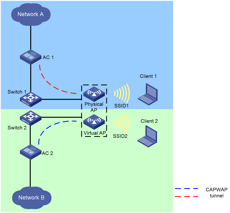
Hardware and feature compatibility
|
Hardware series |
Model |
Product code |
Feature compatibility |
|
WX1800H series |
WX1804H-PWR |
EWP-WX1804H-PWR-CN |
Yes |
|
WX2500H series |
WX2508H-PWR-LTE WX2510H-PWR WX2510H-F-PWR WX2540H WX2540H-F WX2560H |
EWP-WX2508H-PWR-LTE EWP-WX2510H-PWR EWP-WX2510H-F-PWR EWP-WX2540H EWP-WX2540H-F EWP-WX2560H |
Yes |
|
MAK series |
MAK204 MAK206 |
EWP-MAK204 EWP-MAK206 |
No |
|
WX3000H series |
WX3010H WX3010H-X-PWR WX3010H-L-PWR WX3024H WX3024H-L-PWR WX3024H-F |
EWP-WX3010H EWP-WX3010H-X-PWR EWP-WX3010H-L-PWR EWP-WX3024H EWP-WX3024H-L-PWR EWP-WX3024H-F |
Yes |
|
WX3500H series |
WX3508H WX3508H WX3510H WX3510H WX3520H WX3520H-F WX3540H WX3540H |
EWP-WX3508H EWP-WX3508H-F EWP-WX3510H EWP-WX3510H-F EWP-WX3520H EWP-WX3520H-F EWP-WX3540H EWP-WX3540H-F |
Yes |
|
WX5500E series |
WX5510E WX5540E |
EWP-WX5510E EWP-WX5540E |
Yes |
|
WX5500H series |
WX5540H WX5560H WX5580H |
EWP-WX5540H EWP-WX5560H EWP-WX5580H |
Yes |
|
Access controller modules |
LSUM1WCME0 EWPXM1WCME0 LSQM1WCMX20 LSUM1WCMX20RT LSQM1WCMX40 LSUM1WCMX40RT EWPXM2WCMD0F EWPXM1MAC0F |
LSUM1WCME0 EWPXM1WCME0 LSQM1WCMX20 LSUM1WCMX20RT LSQM1WCMX40 LSUM1WCMX40RT EWPXM2WCMD0F EWPXM1MAC0F |
Yes |
|
Hardware series |
Model |
Product code |
Feature compatibility |
|
WX1800H series |
WX1804H-PWR WX1810H-PWR WX1820H WX1840H |
EWP-WX1804H-PWR EWP-WX1810H-PWR EWP-WX1820H EWP-WX1840H-GL |
Yes |
|
WX3800H series |
WX3820H WX3840H |
EWP-WX3820H-GL EWP-WX3840H-GL |
Yes |
|
WX5800H series |
WX5860H |
EWP-WX5860H-GL |
Yes |
Restrictions and guidelines
You can create only one virtual AP for a physical AP.
Make sure the IP address of the AC that manages a physical AP is different from the IP address of the AC that manages its virtual AP and make sure the IP addresses are the same version.
When the virtual AP feature is enabled, the number of BSSs that can be created on a radio decreases by 50%.
Before you disable the virtual AP feature, make sure no virtual AP exists in all AP views and AP group views. If any virtual AP exists, first delete that virtual AP and then disable the virtual AP feature.
For security purposes, you can specify a management VLAN for a virtual AP different from its physical AP. If you do not specify a management VLAN for a virtual AP, you must enable port isolation for an Ethernet interface on that AP.
Before you can specify a management VLAN for a virtual AP, you must assign an Ethernet interface on that AP to the management VLAN and make sure the management VLAN-interface obtains an IP address through DHCP.
Prerequisites
Before you enable this feature, make sure the WLAN ID assigned to the service templates bound to all radios in all AP radio views and AP group radio views is not a value in the second half of the WLAN ID range. If such a WLAN ID exists, you must first unbind the service template and then enable this feature. To view the WLAN IDs assigned to a service template, execute the display system internal wlan bss list ap ap-id radio radio-id command in probe view. The value range for a WLAN ID is from 1 to the maximum number of BSSs that can be created on a radio before the virtual AP feature is enabled.
Procedure
1. Enter system view.
system-view
2. Enable the virtual AP feature.
wlan virtual-ap enable
Before creating a virtual AP, make sure the virtual AP feature has been enabled on the AC.
3. Create a virtual AP and specify the IP address of the AC to which the virtual AP connects.
virtual-ap ac-address { ip ipv4-address | ipv6 ipv6-address } [ management-vlan vlan ]
Configuring automatic AC association for fat APs and cloud-managed APs
About this task
This feature enables fat APs and cloud-managed APs to register with an AC automatically for the AC to manage these APs in a centralized way.
This feature can be used only for AP upgrade or operating mode change.
Restrictions and guidelines
If multiple ACs exist in a network, enable this feature only on the AC from which you want to manage fat APs and cloud-managed APs.
Before enabling this feature, execute the wlan auto-ap enable command to enable the auto AP feature.
Do not configure any commands other than AP upgrade or operating mode change in AP view or AP group view for the fat APs or cloud-managed APs.
Procedure
1. Enter system view.
system-view
2. Enable automatic AC association for fat APs and cloud-managed APs.
wlan auto-ap fat-and-cloud enable
By default, automatic AC association is disabled for fat APs and cloud-managed APs.
Configuring a fat AP or cloud-managed AP to operate in fit mode
About this task
For unified management of fat APs or cloud-managed APs, you can configure them to operate in fit mode.
After you configure this feature for a fat AP or cloud-managed AP, it performs either of the following tasks:
· If a fit AP image exists on the AP, the AP restarts and changes its mode immediately.
· If no fit AP image exists on the AP, the AP first attempts to obtain a fit AP image from the AC after associating with the AC and then restarts and changes the mode. If the AP fails to obtain a fit AP image, it does not change its mode. The image downloading process might take several or dozens of minutes.
Restrictions and guidelines
After image downloading starts, do not perform any operations on the AP until the mode change fails or finishes.
If the AP is already in fit mode, this configuration does not affect AP operation.
If the AP is offline, save the configuration on the AC. The AP will automatically perform a mode change next time it comes online.
Make sure the AC connection feature is enabled on the target AP. To enable this feature, use the wlan connect-ac enable command.
Procedure
1. Enter system view.
system-view
2. Enter AP view or AP group's AP model view.
¡ Enter AP view.
wlan ap ap-name
¡ Enter AP group view.
wlan ap-group group-name
3. Configure the fat AP or cloud-managed AP to operate in fit mode.
ap-mode fit
By default:
¡ In AP view, the AP uses the configuration in AP group view.
¡ In AP group view, a fat AP operates in fat mode and a cloud-managed AP operate in cloud mode.
Switching the operating mode for a fit AP
About this task
Perform this task to switch the operating mode of a fit AP to cloud.
Restrictions and guidelines
· For the configuration to take effect, use the reset wlan ap command to restart the AP after the configuration.
· For the first operating mode switching, an AP restarts with the factory default configuration. If it is not the first operation mode switching and the configuration has been saved with the save command, the AP restarts with the saved configuration. If the configuration has not been saved, the AP restarts with the factory default configuration.
· This feature takes effect only on online APs.
· If the AC associated with an AP is the backup AC for the AP, you cannot configure this feature on the AC.
Procedure
1. Enter system view.
system-view
2. Switch the operating mode for an AP.
wlan mode-switch ap ap-namecloud
Enabling 5 GHz radio virtualization
|
|
NOTE: Support for this feature depends on the AP model. |
About this task
5 GHz radio virtualization splits the 5 GHz radio on an AP that has a 2.4 GHz radio and a 5-GHz 8 × 8 mode radio into two 5-GHz 4 × 4 mode radios. With this feature enabled, a dual-radio AP can operate in triple-radio mode.
The following compatibility matrixes show the support of hardware platforms for this feature:
|
Hardware series |
Model |
Product code |
Feature compatibility |
|
WX1800H series |
WX1804H-PWR |
EWP-WX1804H-PWR-CN |
Yes |
|
WX2500H series |
WX2508H-PWR-LTE WX2510H-PWR WX2510H-F-PWR WX2540H WX2540H-F WX2560H |
EWP-WX2508H-PWR-LTE EWP-WX2510H-PWR EWP-WX2510H-F-PWR EWP-WX2540H EWP-WX2540H-F EWP-WX2560H |
Yes |
|
MAK series |
MAK204 MAK206 |
EWP-MAK204 EWP-MAK206 |
No |
|
WX3000H series |
WX3010H WX3010H-X-PWR WX3010H-L-PWR WX3024H WX3024H-L-PWR WX3024H-F |
EWP-WX3010H EWP-WX3010H-X-PWR EWP-WX3010H-L-PWR EWP-WX3024H EWP-WX3024H-L-PWR EWP-WX3024H-F |
Yes |
|
WX3500H series |
WX3508H WX3508H WX3510H WX3510H WX3520H WX3520H-F WX3540H WX3540H |
EWP-WX3508H EWP-WX3508H-F EWP-WX3510H EWP-WX3510H-F EWP-WX3520H EWP-WX3520H-F EWP-WX3540H EWP-WX3540H-F |
Yes |
|
WX5500E series |
WX5510E WX5540E |
EWP-WX5510E EWP-WX5540E |
Yes |
|
WX5500H series |
WX5540H WX5560H WX5580H |
EWP-WX5540H EWP-WX5560H EWP-WX5580H |
Yes |
|
Access controller modules |
LSUM1WCME0 EWPXM1WCME0 LSQM1WCMX20 LSUM1WCMX20RT LSQM1WCMX40 LSUM1WCMX40RT EWPXM2WCMD0F EWPXM1MAC0F |
LSUM1WCME0 EWPXM1WCME0 LSQM1WCMX20 LSUM1WCMX20RT LSQM1WCMX40 LSUM1WCMX40RT EWPXM2WCMD0F EWPXM1MAC0F |
Yes |
|
Hardware series |
Model |
Product code |
Feature compatibility |
|
WX1800H series |
WX1804H-PWR WX1810H-PWR WX1820H WX1840H |
EWP-WX1804H-PWR EWP-WX1810H-PWR EWP-WX1820H EWP-WX1840H-GL |
Yes |
|
WX3800H series |
WX3820H WX3840H |
EWP-WX3820H-GL EWP-WX3840H-GL |
Yes |
|
WX5800H series |
WX5860H |
EWP-WX5860H-GL |
Yes |
Restrictions and guidelines
Before you configure 5 GHz radio virtualization, perform the following tasks:
· Disable the auto AP feature.
· Delete the manual APs for which you want to enable this feature. If the manual APs belong to an AP group, also delete the manual APs from that AP group.
After you configure 5 GHz radio virtualization, reconfigure the target APs. The APs will reboot automatically during the association process to switch to triple-radio mode.
Procedure
1. Enter system view.
system-view
2. Enable 5 GHz radio virtualization.
wlan virtual-5g-radio enable { all | ap-model ap-model }
By default, 5 GHz radio virtualization is disabled. A 5 GHz radio will not be virtualized into two 5 GHz radios.
Configuring AP power management
Configuring the default input power level
|
|
NOTE: Support for this feature depends on the AP model. |
About this task
Configure the default input power level for an AP in case the AP cannot obtain its input power level at startup.
An AP automatically detects power supply modes to obtain its input power level at startup. If the AP fails to obtain the input power level, it operates at the low power level before associating with an AC. After the association, it operates at the configured default input power level.
An AP can be powered through a power adapter or through its PoE or PoE+ ports. The following table shows the relationship between the AP's power supply mode and input power level:
|
Power supply mode |
Input power level |
|
· Power adapter. · Multiple PoE+ ports. · Combination of PoE and PoE+ ports. |
High |
|
· Single PoE+ port · Multiple PoE ports |
Middle |
|
Single PoE port |
Low |
An AP's support for MIMO modes and USB interfaces varies by input power level, as shown in Table 1.
Table 1 AP's support for MIMO modes and USB interfaces
|
Input power level |
Supported MIMO modes |
Whether USB interfaces can be enabled |
|
High |
1×1, 2×2, 3×3, and 4×4. |
Yes. |
|
Middle |
1×1, 2×2, 3×3, and 4×4. |
Yes when the MIMO mode is 1×1 or 2×2. |
|
Low |
1×1. |
No. |
Restrictions and guidelines
When you configure the default input power level for an AP, make sure the setting matches its power mode. An excessively low input power level prevents the AP from operating correctly. An excessively high input power level causes overload of the AP in case of power shortage.
Procedure
1. Enter system view.
system-view
2. Enter AP view or an AP group's AP model view.
¡ Enter AP view.
wlan ap ap-name
¡ Execute the following commands in sequence to enter an AP group's AP model view:
wlan ap-group group-name
ap-model ap-model
3. Configure the default input power level.
power-level default { high | low | middle }
By default:
¡ In AP view, an AP uses the configuration in an AP group's AP model view.
¡ In an AP group's AP model view, the default input power level is middle.
Enabling or disabling USB interfaces for APs
|
|
NOTE: Support for this feature depends on the AP model. |
About this task
After you enable USB interfaces for an AP, the USB interfaces become active only when either of the following requirements is met:
· The input power level of the AP is high.
· The input power level of the AP is middle and the MIMO mode is 1×1 or 2×2.
For information about input power levels, see "Configuring the default input power level." For information about MIMO modes, see radio management in Radio Resources Management Configuration Guide.
Procedure
1. Enter system view.
system-view
2. Enter AP view or an AP group's AP model view.
¡ Enter AP view.
wlan ap ap-name
¡ Execute the following commands in sequence to enter an AP group's AP model view:
wlan ap-group group-name
ap-model ap-model
3. Enable or disable USB interfaces.
usb { enable | disable }
By default:
In AP view, an AP uses the configuration in an AP group's AP model view.
In an AP group's AP model view, USB interfaces are disabled.
Enabling or disabling PoE for PIs
|
|
NOTE: Support for this feature depends on the AP model. |
1. Enter system view.
system-view
2. Enter AP view or an AP group's AP model view.
¡ Enter AP view.
wlan ap ap-name
¡ Execute the following commands in sequence to enter an AP group's AP model view:
wlan ap-group group-name
ap-model ap-model
3. Enable or disable PoE for PIs.
poe port port-number1 [ to port-number2 ] { disable | enable }
By default:
¡ In AP view, an AP uses the configuration in an AP group's AP model view.
¡ In an AP group's AP model view, PoE is disabled on PIs.
Maintaining ACs
Configuring a description for the AC
1. Enter system view.
system-view
2. Configure a description for the AC.
wlan description text
By default, an AC does not have a description.
Enabling time zone synchronization
About this task
This feature enables APs to synchronize time and time zone information from the AC at association and at specific intervals after association.
Procedure
1. Enter system view.
system-view
2. Enable time zone synchronization.
wlan timezone-sync enable
By default, time zone synchronization is enabled.
Loading an APDB user script
About this task
This task allows you to add new AP models to the APDB without upgrading AC software.
Restrictions and guidelines
Make sure the user script is valid. Invalid scripts can cause loading failure.
The AP models in the user script must be different from the AP models in the system script.
If you load multiple user scripts on the AC, the most recently loaded user script overwrites the old user scripts.
To reload a user script when the following conditions exist, you must delete the related AP models or use the wlan apdb command to restore the original software version:
· A manual AP or an online auto AP whose model is listed in the old user script exists.
· APs of an AP model listed in the old user script have been added to an AP group.
· The old user script includes an AP model whose software version was already configured.
For more information about the wlan apdb command, see AP management commands in AP and WT Management Command Reference.
To prevent AP model configuration lost after an AC reboot, you must reload a user script when you rename, or delete the user script in the file system.
When you replace a user script, the AP model configuration in the old user script will be lost upon an AC reboot if the new user script does not contain AP model configuration of the old script. In this case, you must reload the new user script.
Procedure
1. Enter system view.
system-view
2. Load an APDB user script.
wlan apdb file user.apdb
By default, no user script is loaded on the AC.
Enabling service anomaly detection
|
|
CAUTION: If you disable this feature, you can only manually restart the AC to restore services. Do not disable this feature unless necessary. |
About this task
This feature enables an AC to check service status and start a reboot timer upon detecting that no APs are associated with the AC. When the reboot timer (10 minutes) expires, the AC restarts. If an AP comes online on the AC before the reboot timer expires, the AC deletes the timer.
Procedure
1. Enter system view.
system-view
2. Enable service anomaly detection.
wlan detect-anomaly enable
By default, service anomaly detection is enabled.
Disabling the WLAN function
About this task
|
|
CAUTION: · Make sure WLAN-related features will not be used any more before you disable the WLAN function. · Disabling the WLAN function logs off all online APs. Please use this feature with caution. |
This feature disables the device from providing WLAN services and releases ports used by CAPWAP and LWAPP tunnels.
Procedure
1. Enter system view.
system-view
2. Disable the WLAN function.
undo wlan enable
By default, the WLAN function is enabled.
Configuring an AP monitor group
About AP monitor groups
APs in an AP monitor group can report client quantity, radio traffic, channel usage, and AP anomalies to the AC, which reports the information to the Cloudnet platform. You can view the running state, health state, and detailed information for APs in the AP monitor group on the Smart O&M component of the Cloudnet platform.
Restrictions and guidelines
You can add a maximum of 32 APs to an AP monitor group.
Procedure
1. Enter system view.
system-view
2. Create an AP monitor group and enter its view.
wlan vip-ap-group
3. Add an AP to the AP monitor group.
ap-name ap-name
By default, no APs exist in an AP monitor group.
4. (Optional.) Set the interval at which the AP reports statistics to the AC.
report-interval interval
By default, an AP reports statistics to the AC at intervals of 50 seconds.
Display and maintenance commands for AP management
|
|
IMPORTANT: The WX1800H series, WX2500H series, MAK series, and WX3000H series access controllers do not support parameters or commands that are available only in IRF mode. |
Execute display commands in any view and reset commands in user view.
|
Task |
Command |
|
Display information about all APs or the specified AP. |
display wlan ap { all | apid ap-id | name ap-name } [ verbose ] |
|
Display address information for all APs or the specified AP. |
display wlan ap { all | name ap-name } address |
|
Display configuration status of CAPWAP features. |
display wlan ap all feature capwap |
|
Display AP connection records on the AC. |
display wlan ap { all | name ap-name } connection-record |
|
Display AP descriptions on the AC. |
display wlan ap description |
|
Display GPS information for all APs or the specified AP. |
display wlan ap { all | name ap-name } gps |
|
Display AP group information for all APs or the specified AP. |
display wlan ap { all | name ap-name } group |
|
Display Ethernet interface statistics about online APs. |
display wlan ap { all | name ap-name } interface [ verbose ] |
|
Display AP online duration. |
display wlan ap { all | name ap-name } online-time |
|
Display the reboot logs of the specified AP. |
display wlan ap name ap-name reboot-log |
|
Display region code information for APs. |
display wlan ap { all | name ap-name } region-code |
|
Display running configuration for all APs or the specified AP. |
display wlan ap { all | name ap-name } running-configuration [ verbose ] |
|
Display tunnel latency information for the specified CAPWAP tunnel. |
display wlan ap name ap-name tunnel latency |
|
Display association failure records for APs. |
display wlan ap statistics association-failure-record |
|
Display information about AP image downloading. |
display wlan ap statistics image-download [ failed | in-progress | succeeded ] |
|
Display online AP quantity records. |
display wlan ap statistics online-record [ datetime date time [ count count ] ] |
|
Display CAPWAP tunnel down records. |
display wlan ap statistics tunnel-down-record |
|
Display information about distribution of attached APs for ACs. |
In standalone mode: display wlan ap-distribution { all | local-ac-name local-ac-name } In IRF mode: display wlan ap-distribution { all | local-ac-name local-ac-name | slot slot-number } |
|
Display the attachment location of an AP. |
display wlan ap-distribution ap-name ap-name |
|
Display information about all AP groups or the specified AP group. |
display wlan ap-group [ brief | name group-name ] |
|
Display AP model information. |
display wlan ap-model { all | name model-name } |
|
Display the WLAN device role. |
display wlan device role |
|
Display the number of installed WLAN licenses. |
display wlan license |
|
Display virtual AP information. |
display wlan virtual-ap { all | name ap-name } |
|
Display virtual AP group information. |
display wlan virtual-ap-group [ brief | name group-name ] |
|
Clear AP connection records on the AC. |
reset wlan ap { all | name ap-name } connection-record |
|
Delete configuration file wlan_ap_prvs.xml from all APs or the specified AP. |
reset wlan ap provision { all | name ap-name } |
|
Clear the reboot logs of all APs or the specified AP. |
reset wlan ap reboot-log { all | name ap-name } |
|
Clear tunnel latency information for all CAPWAP tunnels or the specified CAPWAP tunnel. |
reset wlan tunnel latency ap { all | name ap-name } |
AP management configuration examples
The AP models and serial numbers in this document are used only as examples. Support for AP models and serial numbers depends on the AC model.
Example: Establishing a CAPWAP tunnel through DHCP
Network configuration
As shown in Figure 4, configure the AP to obtain its IP address and AC IP address from the DHCP server through DHCP Option 43. The AP uses the IP address of the AC to establish a CAPWAP tunnel with the AC.

Procedure
1. Configure the DHCP server:
# Enable the DHCP service.
[DHCP server] dhcp enable
# Configure DHCP address pool 1.
[DHCP server] dhcp server ip-pool 1
[DHCP server-dhcp-pool-1] network 1.1.1.0 mask 255.255.255.0
# Configure Option 43 to specify the IP address of the AC in address pool 0. The right-most bytes 01010103 (1.1.1.3) represent the IP address of the AC.
[DHCP server-dhcp-pool-1] option 43 hex 800700000101010103
[DHCP Server-dhcp-pool-1] quit
[DHCP Server] quit
2. Configure the AC:
# Set the IP address of VLAN-interface 1 on the AC to 1.1.1.3/24.
[AC] interface vlan-interface 1
[AC-Vlan-interface1] ip address 1.1.1.3 24
[AC-Vlan-interface1] quit
# Create an AP named ap1, and set its serial ID to 219801A28N819CE0002T.
[AC] wlan ap ap1 model WA6320
[AC-wlan-ap-ap1] serial-id 219801A28N819CE0002T
[AC-wlan-ap-ap1] quit
# Start up the AP. The AP performs the following operations:
¡ Obtains its IP address 1.1.1.2 from the DHCP server.
¡ Obtains the IP address of the AC through Option 43.
¡ Establishes a CAPWAP tunnel with the AC.
Verifying the configuration
# Verify that you can see the following information:
· The AP obtains the IP address of the AC through DHCP.
· The AP and the AC have established a CAPWAP tunnel.
· The AP is in Run state.
[AC] display wlan ap name ap1 verbose
AP name : ap1
AP ID : 1
AP group name : default-group
State : Run
Backup type : Master
Online time : 0 days 1 hours 25 minutes 12 seconds
System up time : 0 days 2 hours 22 minutes 12 seconds
Model : WA6320
Region code : CN
Region code lock : Disable
Serial ID : 219801A28N819CE0002T
MAC address : 0AFB-423B-893C
IP address : 1.1.1.2
UDP control port number : 26147
UDP data port number : 26147
H/W version : Ver.C
S/W version : E2321
Boot version : 1.01
USB state : N/A
Power level : N/A
Power info : N/A
Description : wtp1
Priority : 4
Echo interval : 10 seconds
Echo count : 3 counts
Keepalive interval : 10 seconds
Discovery-response wait-time : 2 seconds
Statistics report interval : 50 seconds
Fragment size (data) : 1500
Fragment size (control) : 1450
MAC type : Local MAC & Split MAC
Tunnel mode : Local Bridging & 802.3 Frame & Native Frame
CWPCAP data-tunnel status : Up
Discovery type : DHCP
Retransmission count : 3
Retransmission interval : 5 seconds
Firmware upgrade : Enabled
Sent control packets : 1
Received control packets : 1
Echo requests : 147
Lost echo responses : 0
Average echo delay : 3
Last reboot reason : User soft reboot
Latest IP address : 10.1.0.2
Current AC IP : N/A
Tunnel down reason : Request wait timer expired
Connection count : 1
Backup Ipv4 : Not configured
Backup Ipv6 : Not configured
Ctrl-tunnel encryption : Disabled
Ctrl-tunnel encryption state : Not encrypted
Tunnel encryption : Disabled
Data-tunnel encryption : Disabled
Data-tunnel encryption state : Not encrypted
LED mode : Normal
Remote configuration : Enabled
AP type : Unknown
Radio 1:
Basic BSSID : 7848-59f6-3940
State : Up
Type : 802.11ax
Antenna type : internal
Client dot11ac-only : Disabled
Client dot11n-only : Disabled
Channel bandwidth : 20/40/80MHz
Operating bandwidth : 20/40/80MHz
Secondary channel mode : SCA
Short GI for 20MHz : Supported
Short GI for 40MHz : Supported
Short GI for 80MHz : Supported
Short GI for 160MHz : Not supported
MIMO : Not Config
Green-Energy-Management : Disabled
A-MSDU : Enabled
A-MPDU : Enabled
LDPC : Not Supported
STBC : Supported
Operational VHT-MCS Set:
Mandatory : Not configured
Supported : NSS1 0,1,2,3,4,5,6,7,8,9
NSS2 0,1,2,3,4,5,6,7,8,9
Multicast : Not configured
Operational HT MCS Set:
Mandatory : Not configured
Supported : 0, 1, 2, 3, 4, 5, 6, 7, 8, 9,
10, 11, 12, 13, 14, 15
Multicast : Not configured
Channel : 44(auto)
Channel usage(%) : 15
Max power : 20 dBm
Operational rate:
Mandatory : 6, 12, 24 Mbps
Multicast : Auto
Supported : 9, 18, 36, 48, 54 Mbps
Disabled : Not configured
Distance : 1 km
ANI : Enabled
Fragmentation threshold : 2346 bytes
Beacon interval : 100 TU
Protection threshold : 2346 bytes
Long retry threshold : 4
Short retry threshold : 7
Frame aging time in cache : 2000 ms
Noise floor : -102 dBm
Smart antenna : Enabled
Smart antenna policy : Auto
Protection mode : cts-to-self
MU-TxBF : Enabled
SU-TxBF : Enabled
Continuous mode : N/A
HT protection mode : No protection
ATF : Disabled
Radio 2:
Basic BSSID : 7848-59f6-3950
State : Down
Type : 802.11gax
Antenna type : internal
Client dot11n-only : Disabled
Channel bandwidth : 20MHz
Operating bandwidth : 20MHz
Secondary channel mode : SCN
Short GI for 20MHz : Supported
Short GI for 40MHz : Supported
A-MSDU : Enabled
A-MPDU : Enabled
LDPC : Not Supported
STBC : Supported
Operational HT MCS Set:
Mandatory : Not configured
Supported : 0, 1, 2, 3, 4, 5, 6, 7, 8, 9,
10, 11, 12, 13, 14, 15
Multicast : Not configured
Channel : 5(auto)
Channel usage(%) : 0
Max power : 20 dBm
Preamble type : Short
Operational rate:
Mandatory : 1, 2, 5.5, 11 Mbps
Multicast : Auto
Supported : 6, 9, 12, 18, 24, 36, 48, 54 Mbps
Disabled : Not configured
Distance : 1 km
ANI : Enabled
Fragmentation threshold : 2346 bytes
Beacon interval : 100 TU
Protection threshold : 2346 bytes
Long retry threshold : 4
Short retry threshold : 7
Frame aging time in cache : 2000 ms
Noise floor : 0 dBm
Smart antenna : Enabled
Smart antenna policy : Auto
Protection mode : cts-to-self
Continuous mode : N/A
HT protection mode : No protection
ATF : Disabled
Example: Establishing a CAPWAP tunnel through DHCPv6
Network configuration
As shown in Figure 5, configure the AP to obtain its IP address and AC IP address from the DHCPv6 server through DHCP Option 52. The AP uses the IP address of the AC to establish a CAPWAP tunnel with the AC.
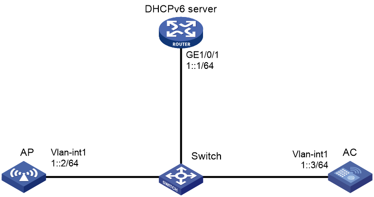
Procedure
1. Configure the DHCPv6 server:
# Assign an IPv6 address to GigabitEthernet 1/0/1.
<DHCPv6 Server> system-view
[DHCPv6 Server] interface gigabitethernet 1/0/1
[DHCPv6 Server-GigabitEthernet1/0/1] ipv6 address 1::1/64
# Disable RA message advertising suppression.
[DHCPv6 Server-GigabitEthernet1/0/1] undo ipv6 nd ra halt
# Set the managed address configuration flag (M) to 1 in RA advertisements to be sent.
[DHCPv6 Server-GigabitEthernet1/0/1] ipv6 nd autoconfig managed-address-flag
# Set the other stateful configuration flag (O) to 1 in RA advertisements to be sent.
[DHCPv6 Server-GigabitEthernet1/0/1] ipv6 nd autoconfig other-flag
# Enable the DHCPv6 service on GigabitEthernet 1/0/1.
[DHCPv6 Server-GigabitEthernet1/0/1] ipv6 dhcp select server
[DHCPv6 Server-GigabitEthernet1/0/1] quit
# Create a DHCPv6 address pool, and specify an IPv6 subnet for dynamic allocation in the DHCPv6 address pool.
[DHCPv6 Server] ipv6 dhcp pool 1
[DHCPv6 Server-dhcp6-pool-1] network 1::0/64
# Configure Option 52 that specifies an AC address 1::3 in DHCPv6 address pool 1.
[DHCPv6 Server-dhcp-pool-1] option 52 hex 00010000000000000000000000000003
[DHCPv6 Server-dhcp-pool-1] quit
[DHCPv6 Server] quit
2. Configure the AC:
# Set the IP address of VLAN-interface 1 to 1::3/64.
<AC> system-view
[AC] interface vlan-interface 1
[AC-Vlan-interface1] ipv6 address 1::3 64
# Create an AP named ap1, and set its serial ID to 219801A28N819CE0002T.
[AC-wlan-ap-ap1] serial-id 219801A28N819CE0002T
[AC-wlan-ap-ap1] quit
# Start up the AP. The AP performs the following operations:
¡ Obtains its IPv6 address 1::2 from the DHCP server.
¡ Obtains the IPv6 address of the AC through Option 52.
¡ Establishes a CAPWAP tunnel with the AC.
Verifying the configuration
# Verify that you can view the following information:
· The AP obtains the IP address of the AC through DHCP.
· The AP and the AC have established a CAPWAP tunnel.
· The AP is in Run state.
[AC] display wlan ap name ap1 verbose
AP name : ap1
AP ID : 1
AP group name : default-group
State : Run
Backup type : Master
Online time : 0 days 1 hours 25 minutes 12 seconds
System up time : 0 days 2 hours 22 minutes 12 seconds
Model : WA6320
Region code : CN
Region code lock : Disable
Serial ID : 219801A28N819CE0002T
MAC address : 0AFB-423B-893C
IP address : 1::2
UDP control port number : 26147
UDP data port number : 26147
H/W version : Ver.C
S/W version : E2321
Boot version : 1.01
USB state : N/A
Power level : N/A
Power info : N/A
Description : wtp1
Priority : 4
Echo interval : 10 seconds
Echo count : 3 counts
Keepalive interval : 10 seconds
Discovery-response wait-time : 2 seconds
Statistics report interval : 50 seconds
Fragment size (data) : 1500
Fragment size (control) : 1450
MAC type : Local MAC & Split MAC
Tunnel mode : Local Bridging & 802.3 Frame & Native Frame
CWPCAP data-tunnel status : Up
Discovery type : DHCP
Retransmission count : 3
Retransmission interval : 5 seconds
Firmware upgrade : Enabled
Sent control packets : 1
Received control packets : 1
Echo requests : 147
Lost echo responses : 0
Average echo delay : 3
Last reboot reason : User soft reboot
Latest IP address : 10.1.0.2
Current AC IP : N/A
Tunnel down reason : Request wait timer expired
Connection count : 1
Backup Ipv4 : Not configured
Backup Ipv6 : Not configured
Ctrl-tunnel encryption : Disabled
Ctrl-tunnel encryption state : Not encrypted
Tunnel encryption : Disabled
Data-tunnel encryption : Disabled
Data-tunnel encryption state : Not encrypted
LED mode : Normal
Remote configuration : Enabled
AP type : Unknown
Radio 1:
Basic BSSID : 7848-59f6-3940
State : Up
Type : 802.11ax
Antenna type : internal
Client dot11ac-only : Disabled
Client dot11n-only : Disabled
Channel bandwidth : 20/40/80MHz
Operating bandwidth : 20/40/80MHz
Secondary channel mode : SCA
Short GI for 20MHz : Supported
Short GI for 40MHz : Supported
Short GI for 80MHz : Supported
Short GI for 160MHz : Not supported
MIMO : Not Config
Green-Energy-Management : Disabled
A-MSDU : Enabled
A-MPDU : Enabled
LDPC : Not Supported
STBC : Supported
Operational VHT-MCS Set:
Mandatory : Not configured
Supported : NSS1 0,1,2,3,4,5,6,7,8,9
NSS2 0,1,2,3,4,5,6,7,8,9
Multicast : Not configured
Operational HT MCS Set:
Mandatory : Not configured
Supported : 0, 1, 2, 3, 4, 5, 6, 7, 8, 9,
10, 11, 12, 13, 14, 15
Multicast : Not configured
Channel : 44(auto)
Channel usage(%) : 15
Max power : 20 dBm
Operational rate:
Mandatory : 6, 12, 24 Mbps
Multicast : Auto
Supported : 9, 18, 36, 48, 54 Mbps
Disabled : Not configured
Distance : 1 km
ANI : Enabled
Fragmentation threshold : 2346 bytes
Beacon interval : 100 TU
Protection threshold : 2346 bytes
Long retry threshold : 4
Short retry threshold : 7
Frame aging time in cache : 2000 ms
Noise floor : -102 dBm
Smart antenna : Enabled
Smart antenna policy : Auto
Protection mode : cts-to-self
MU-TxBF : Enabled
SU-TxBF : Enabled
Continuous mode : N/A
HT protection mode : No protection
ATF : Disabled
Radio 2:
Basic BSSID : 7848-59f6-3950
State : Down
Type : 802.11gax
Antenna type : internal
Client dot11n-only : Disabled
Channel bandwidth : 20MHz
Operating bandwidth : 20MHz
Secondary channel mode : SCN
Short GI for 20MHz : Supported
Short GI for 40MHz : Supported
A-MSDU : Enabled
A-MPDU : Enabled
LDPC : Not Supported
STBC : Supported
Operational HT MCS Set:
Mandatory : Not configured
Supported : 0, 1, 2, 3, 4, 5, 6, 7, 8, 9,
10, 11, 12, 13, 14, 15
Multicast : Not configured
Channel : 5(auto)
Channel usage(%) : 0
Max power : 20 dBm
Preamble type : Short
Operational rate:
Mandatory : 1, 2, 5.5, 11 Mbps
Multicast : Auto
Supported : 6, 9, 12, 18, 24, 36, 48, 54 Mbps
Disabled : Not configured
Distance : 1 km
ANI : Enabled
Fragmentation threshold : 2346 bytes
Beacon interval : 100 TU
Protection threshold : 2346 bytes
Long retry threshold : 4
Short retry threshold : 7
Frame aging time in cache : 2000 ms
Noise floor : 0 dBm
Smart antenna : Enabled
Smart antenna policy : Auto
Protection mode : cts-to-self
Continuous mode : N/A
HT protection mode : No protection
ATF : Disabled
Example: Establishing a CAPWAP tunnel through DNS
Network configuration
As shown in Figure 6, configure the AP to obtain the IP address of the AC through DNS to establish a CAPWAP tunnel with the AC.
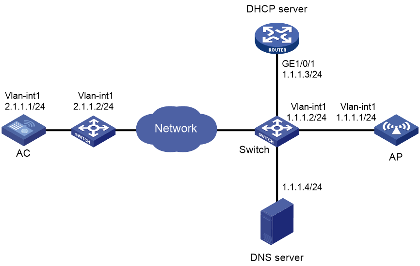
Procedure
1. Configure the DHCP server:
# Enable the DHCP service, configure DHCP address pool 1, and set the domain name suffix of the AC to abc.
[DHCP server] dhcp enable
[DHCP server] dhcp server ip-pool 1
[DHCP server-dhcp-pool-1] network 1.1.1.0 mask 255.255.255.0
[DHCP server-dhcp-pool-1] domain-name abc
[DHCP server-dhcp-pool-1] dns-list 1.1.1.4
[DHCP server-dhcp-pool-1] gateway-list 1.1.1.2
[DHCP server-dhcp-pool-1] quit
[DHCP server] quit
2. Configure a mapping between domain name h3c.abc and IP address 2.1.1.1/24. For more information, see Layer 3—IP Services Configuration Guide. (Details not shown.)
3. Configure the AC:
# Set the IP address of VLAN-interface 1 to 2.1.1.1/24.
[AC] interface vlan-interface 1
[AC-Vlan-interface1] ip address 2.1.1.1 24
[AC-Vlan-interface1] quit
# Configure a default route with next hop address 2.1.1.2.
[AC] ip route-static 0.0.0.0 0 2.1.1.2
# Create an AP named ap1, and set its serial ID to 219801A28N819CE0002T.
[AC] wlan ap ap1 model WA6320
[AC-wlan-ap-ap1] serial-id 219801A28N819CE0002T
# Start up the AP.
[AC-wlan-ap-ap1] quit
The AP performs the following operations:
¡ Obtains its IP address 1.1.1.1, the domain name suffix of the AC, and the IP address of the DNS server from the DHCP server.
¡ Adds the domain name suffix to the hostname.
¡ Informs the DNS client to translate the domain name into an IP address.
¡ Uses the IP address of the AC to establish a CAPWAP tunnel with the AC.
Verifying the configuration
# Verify that you can see the following information:
· The AP and the AC have established a CAPWAP tunnel.
· The AP is in Run state.
· The AP obtains the IP address of the AC through DNS.
[AC] display wlan ap name ap1 verbose
AP name : ap1
AP ID : 1
AP group name : default-group
State : Run
Backup type : Master
Online time : 0 days 1 hours 25 minutes 12 seconds
System up time : 0 days 2 hours 22 minutes 12 seconds
Model : WA6320
Region code : CN
Region code lock : Disable
Serial ID : 219801A28N819CE0002T
MAC address : 0AFB-423B-893C
IP address : 1.1.1.1
UDP control port number : 26147
UDP data port number : 26147
H/W version : Ver.C
S/W version : E2321
Boot version : 1.01
USB state : N/A
Power level : N/A
Power info : N/A
Description : wtp1
Priority : 4
Echo interval : 10 seconds
Echo count : 3 counts
Keepalive interval : 10 seconds
Discovery-response wait-time : 2 seconds
Statistics report interval : 50 seconds
Fragment size (data) : 1500
Fragment size (control) : 1450
MAC type : Local MAC & Split MAC
Tunnel mode : Local Bridging & 802.3 Frame & Native Frame
CWPCAP data-tunnel status : Up
Discovery type : DNS
Retransmission count : 3
Retransmission interval : 5 seconds
Firmware upgrade : Enabled
Sent control packets : 1
Received control packets : 1
Echo requests : 147
Lost echo responses : 0
Average echo delay : 3
Last reboot reason : User soft reboot
Latest IP address : 10.1.0.2
Current AC IP : N/A
Tunnel down reason : Request wait timer expired
Connection count : 1
Backup Ipv4 : Not configured
Backup Ipv6 : Not configured
Ctrl-tunnel encryption : Disabled
Ctrl-tunnel encryption state : Not encrypted
Tunnel encryption : Disabled
Data-tunnel encryption : Disabled
Data-tunnel encryption state : Not encrypted
LED mode : Normal
Remote configuration : Enabled
AP type : Unknown
Radio 1:
Basic BSSID : 7848-59f6-3940
State : Up
Type : 802.11ax
Antenna type : internal
Client dot11ac-only : Disabled
Client dot11n-only : Disabled
Channel bandwidth : 20/40/80MHz
Operating bandwidth : 20/40/80MHz
Secondary channel mode : SCA
Short GI for 20MHz : Supported
Short GI for 40MHz : Supported
Short GI for 80MHz : Supported
Short GI for 160MHz : Not supported
MIMO : Not Config
Green-Energy-Management : Disabled
A-MSDU : Enabled
A-MPDU : Enabled
LDPC : Not Supported
STBC : Supported
Operational VHT-MCS Set:
Mandatory : Not configured
Supported : NSS1 0,1,2,3,4,5,6,7,8,9
NSS2 0,1,2,3,4,5,6,7,8,9
Multicast : Not configured
Operational HT MCS Set:
Mandatory : Not configured
Supported : 0, 1, 2, 3, 4, 5, 6, 7, 8, 9,
10, 11, 12, 13, 14, 15
Multicast : Not configured
Channel : 44(auto)
Channel usage(%) : 15
Max power : 20 dBm
Operational rate:
Mandatory : 6, 12, 24 Mbps
Multicast : Auto
Supported : 9, 18, 36, 48, 54 Mbps
Disabled : Not configured
Distance : 1 km
ANI : Enabled
Fragmentation threshold : 2346 bytes
Beacon interval : 100 TU
Protection threshold : 2346 bytes
Long retry threshold : 4
Short retry threshold : 7
Frame aging time in cache : 2000 ms
Noise floor : -102 dBm
Smart antenna : Enabled
Smart antenna policy : Auto
Protection mode : cts-to-self
MU-TxBF : Enabled
SU-TxBF : Enabled
Continuous mode : N/A
HT protection mode : No protection
ATF : Disabled
Radio 2:
Basic BSSID : 7848-59f6-3950
State : Down
Type : 802.11gax
Antenna type : internal
Client dot11n-only : Disabled
Chnnel bandwidth : 20MHz
Operating bandwidth : 20MHz
Secondary channel mode : SCN
Short GI for 20MHz : Supported
Short GI for 40MHz : Supported
A-MSDU : Enabled
A-MPDU : Enabled
LDPC : Not Supported
STBC : Supported
Operational HT MCS Set:
Mandatory : Not configured
Supported : 0, 1, 2, 3, 4, 5, 6, 7, 8, 9,
10, 11, 12, 13, 14, 15
Multicast : Not configured
Channel : 5(auto)
Channel usage(%) : 0
Max power : 20 dBm
Preamble type : Short
Operational rate:
Mandatory : 1, 2, 5.5, 11 Mbps
Multicast : Auto
Supported : 6, 9, 12, 18, 24, 36, 48, 54 Mbps
Disabled : Not configured
Distance : 1 km
ANI : Enabled
Fragmentation threshold : 2346 bytes
Beacon interval : 100 TU
Protection threshold : 2346 bytes
Long retry threshold : 4
Short retry threshold : 7
Frame aging time in cache : 2000 ms
Noise floor : 0 dBm
Smart antenna : Enabled
Smart antenna policy : Auto
Protection mode : cts-to-self
Continuous mode : N/A
HT protection mode : No protection
ATF : Disabled
Example: Configuring the auto AP feature
Network configuration
As shown in Figure 7, enable the auto AP feature on the AC. The AP obtains the AC IP address through DHCP Option 43 and establishes a CAPWAP tunnel with the AC.
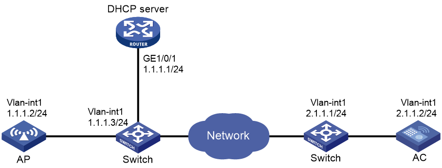
Procedure
1. Configure the DHCP server:
# Enable the DHCP service.
<DHCP server> system-view
[DHCP server] dhcp enable
# Configure DHCP address pool 1.
[DHCP server] dhcp server ip-pool 1
[DHCP server-dhcp-pool-1] network 1.1.1.0 mask 255.255.255.0
# Configure Option 43 to specify the IP address of the AC in address pool 0. The right-most bytes 02010102 (2.1.1.2) represent the IP address of the AC.
[DHCP server-dhcp-pool-1] option 43 ip-address hex 800700000102010102
[DHCP Server-dhcp-pool-1] gateway-list 1.1.1.3
[DHCP Server-dhcp-pool-1] quit
[DHCP Server] quit
2. Configure the AC:
# Set the IP address of VLAN-interface 1 on the AC to 2.1.1.2/24.
[AC] interface vlan-interface 1
[AC-Vlan-interface1] ip address 2.1.1.2 24
[AC-Vlan-interface1] quit
# Configure a default route with next hop address 2.1.1.1.
[AC] ip route-static 0.0.0.0 0 2.1.1.1
# Enable auto AP.
[AC] wlan auto-ap enable
Verifying the configuration
# Verify that the AP has established a CAPWAP tunnel with the AC.
[AC] display wlan ap name 0011-2200-0101 verbose
AP name : 0011-2200-0101
AP ID : 1
AP group name : default-group
State : Run
Backup type : Master
Online time : 0 days 1 hours 25 minutes 12 seconds
System up time : 0 days 2 hours 22 minutes 12 seconds
Model : WA6320
Region code : CN
Region code lock : Disable
Serial ID : 219801A0CNC138011454
MAC address : 0011-2200-0101
IP address : 1.1.1.2
UDP control port number : 26147
UDP data port number : 26147
H/W version : Ver.C
S/W version : E2321
Boot version : 1.01
USB state : N/A
Power level : N/A
Power info : N/A
Description : wtp1
Priority : 4
Echo interval : 10 seconds
Echo count : 3 counts
Keepalive interval : 10 seconds
Discovery-response wait-time : 2 seconds
Statistics report interval : 50 seconds
Fragment size (data) : 1500
Fragment size (control) : 1450
MAC type : Local MAC & Split MAC
Tunnel mode : Local Bridging & 802.3 Frame & Native Frame
CWPCAP data-tunnel status : Up
Discovery type : DHCP
Retransmission count : 3
Retransmission interval : 5 seconds
Firmware upgrade : Enabled
Sent control packets : 1
Received control packets : 1
Echo requests : 147
Lost echo responses : 0
Average echo delay : 3
Last reboot reason : User soft reboot
Latest IP address : 10.1.0.2
Current AC IP : N/A
Tunnel down reason : Request wait timer expired
Connection count : 1
Backup Ipv4 : Not configured
Backup Ipv6 : Not configured
Ctrl-tunnel encryption : Disabled
Ctrl-tunnel encryption state : Not encrypted
Data-tunnel encryption : Disabled
Data-tunnel encryption state : Not encrypted
LED mode : Normal
Remote configuration : Enabled
AP type : Unknown
Radio 1:
Basic BSSID : 7848-59f6-3940
State : Up
Type : 802.11ax
Antenna type : internal
Client dot11ac-only : Disabled
Client dot11n-only : Disabled
Chnnel band-width : 20/40/80MHz
Operating band-width : 20/40/80MHz
Secondary channel mode : SCA
Short GI for 20MHz : Supported
Short GI for 40MHz : Supported
Short GI for 80MHz : Supported
Short GI for 160MHz : Not supported
MIMO : Not Config
Green-Energy-Management : Disabled
A-MSDU : Enabled
A-MPDU : Enabled
LDPC : Not Supported
STBC : Supported
Operational VHT-MCS Set:
Mandatory : Not configured
Supported : NSS1 0,1,2,3,4,5,6,7,8,9
NSS2 0,1,2,3,4,5,6,7,8,9
Multicast : Not configured
Operational HT MCS Set:
Mandatory : Not configured
Supported : 0, 1, 2, 3, 4, 5, 6, 7, 8, 9,
10, 11, 12, 13, 14, 15
Multicast : Not configured
Channel : 44(auto)
Channel usage(%) : 15
Max power : 20 dBm
Operational rate:
Mandatory : 6, 12, 24 Mbps
Multicast : Auto
Supported : 9, 18, 36, 48, 54 Mbps
Disabled : Not configured
Distance : 1 km
ANI : Enabled
Fragmentation threshold : 2346 bytes
Beacon interval : 100 TU
Protection threshold : 2346 bytes
Long retry threshold : 4
Short retry threshold : 7
Frame aging time in cache : 2000 ms
Noise floor : -102 dBm
Smart antenna : Enabled
Smart antenna policy : Auto
Protection mode : cts-to-self
MU-TxBF : Enabled
SU-TxBF : Enabled
Continuous mode : N/A
HT protection mode : No protection
ATF : Disabled
Radio 2:
Basic BSSID : 7848-59f6-3950
State : Down
Type : 802.11gax
Antenna type : internal
Client dot11n-only : Disabled
Channel bandwidth : 20MHz
Operating bandwidth : 20MHz
Secondary channel mode : SCN
Short GI for 20MHz : Supported
Short GI for 40MHz : Supported
A-MSDU : Enabled
A-MPDU : Enabled
LDPC : Not Supported
STBC : Supported
Operational HT MCS Set:
Mandatory : Not configured
Supported : 0, 1, 2, 3, 4, 5, 6, 7, 8, 9,
10, 11, 12, 13, 14, 15
Multicast : Not configured
Channel : 5(auto)
Channel usage(%) : 0
Max power : 20 dBm
Preamble type : Short
Operational rate:
Mandatory : 1, 2, 5.5, 11 Mbps
Multicast : Auto
Supported : 6, 9, 12, 18, 24, 36, 48, 54 Mbps
Disabled : Not configured
Distance : 1 km
ANI : Enabled
Fragmentation threshold : 2346 bytes
Beacon interval : 100 TU
Protection threshold : 2346 bytes
Long retry threshold : 4
Short retry threshold : 7
Frame aging time in cache : 2000 ms
Noise floor : 0 dBm
Smart antenna : Enabled
Smart antenna policy : Auto
Protection mode : cts-to-self
Continuous mode : N/A
HT protection mode : No protection
ATF : Disabled
Example: Configuring AP groups
Network configuration
As shown in Figure 8, configure AP groups and add AP 1 to AP group group1, and AP 2, AP 3, and AP 4 to AP group group2.

Procedure
1. Configure APs to obtain their IP addresses and the AC IP address from the DHCP server. (Details not shown.)
2. Configure manual APs. (Details not shown.)
3. Configure AP groups:
# Create an AP group named group1.
[AC] wlan ap-group group1
# Add AP 1 to AP group group1.
[AC-wlan-ap-group-group1] ap ap1
[AC-wlan-ap-group-group1] quit
# Create an AP group named group2.
# Add AP 2, AP 3, and AP 4 to AP group group2.
[AC-wlan-ap-group-group2] ap ap2 ap3 ap4
[AC-wlan-ap-group-group2] quit
[AC] quit
Verifying the configuration
# Verify that AP 1 is in AP group group1, and AP 2, AP 3, and AP 4 are in AP group group2.
[AC-wlan-ap-group-group2] display wlan ap-group
Total number of AP groups: 3
AP group name : default-group
Description : Not configured
AP model : Not configured
APs : Not configured
AP group name : group1
Description : Not configured
AP model : WA6320
AP grouping rules:
AP name : ap1
Serial ID : Not configured
MAC address : Not configured
IPv4 address : Not configured
IPv6 address : Not configured
APs : ap1 (AP name)
AP group name : group2
Description : Not configured
AP model : WA6320
AP grouping rules:
AP name : ap2, ap3, ap4
Serial ID : Not configured
MAC address : Not configured
IPv4 address : Not configured
IPv6 address : Not configured
APs : ap2 (AP name), ap3 (AP name), ap4 (AP name)
Example: Configuring virtual APs
Network configuration
As shown in Figure 9, the physical AP associates with AC 1 to provide wireless services. Create a virtual AP and associate it with AC 2 to provide wireless services.
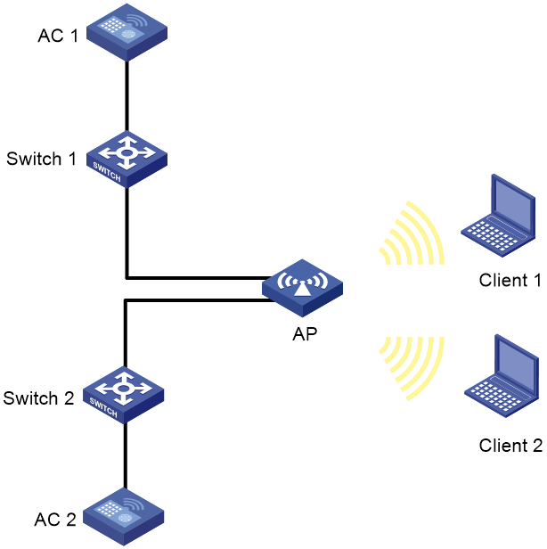
Procedure
1. Configure the switch as the DHCP server to assign an IP address to the AP. (Details not shown.)
2. Configure AC 1:
# Edit the configuration file of the AP and name it as map.txt, and then upload the configuration file to the storage medium on AC 1.
system-view
interface range GigabitEthernet 1/0/1 to GigabitEthernet 1/0/2
port-isolate enable
# Set the IP address of VLAN-interface 1 on AC 1 to 2.1.1.2/24.
<AC1> system-view
[AC1] interface vlan-interface 1
[AC1-Vlan-interface1] ip address 2.1.1.2 24
[AC1-Vlan-interface1] quit
# Enable the virtual AP feature.
[AC1] wlan virtual-ap enable
# Create an AP named ap1, and set its serial ID.
[AC1] wlan ap ap1 model WA6320
[AC1-wlan-ap-ap1] serial-id 219801A28N819CE0002T
# Create a virtual AP on AP ap1, and specify the AC IP address as the IP address of AC 2.
[AC1-wlan-ap-ap1] virtual-ap ac-address ip 2.1.1.3
# Deploy the configuration file to the AP.
[AC1-wlan-ap-ap1] map-configuration map.txt
[AC1-wlan-ap-ap1] quit
3. Configure AC 2:
# Set the IP address of VLAN-interface 1 on AC 2 to 2.1.1.3/24.
<AC2> system-view
[AC2] interface vlan-interface 1
[AC2-Vlan-interface1] ip address 2.1.1.3 24
[AC2-Vlan-interface1] quit
# Create a virtual AP named ap2 on AC 2 with the same model and serial ID with ap1 on AC 1.
[AC2] wlan virtual-ap ap2 model WA6320
[AC2-wlan-virtual-ap-ap2] serial-id 219801A28N819CE0002T
# Disable software upgrade in virtual AP view. Virtual APs do not support software upgrade. If AC 2 and the virtual AP use different software versions, the virtual AP cannot connect to the AC.
[AC2-wlan-virtual-ap-ap2] firmware-upgrade disable
[AC2-wlan-virtual-ap-ap2] quit
Verifying the configuration
# Verify that virtual AP ap2 has established a CAPWAP tunnel with AC 2.
[AC2] display wlan virtual-ap all
Total number of virtual-APs: 1
Total number of connected virtual-APs: 1
Total number of connected common virtual-APs: 1
Total number of connected virtual-WTUs: 0
Maximum supported APs: 256
Remaining APs: 255
AP information
State : I = Idle, J = Join, JA = JoinAck, IL = ImageLoad
C = Config, DC = DataCheck, R = Run, M = Master, B = Backup
AP name APID State Model Serial ID
ap2 1 R/M WA6320 219801A28N819CE0002T