- Table of Contents
-
- 04-Network Connectivity Configuration Guide
- 00-Preface
- 01-About the network connectivity configuration guide
- 02-MAC address table configuration
- 03-Ethernet link aggregation configuration
- 04-Port isolation configuration
- 05-VLAN configuration
- 06-Loop detection configuration
- 07-Spanning tree configuration
- 08-LLDP configuration
- 09-Layer 2 forwarding configuration
- 10-PPP configuration
- 11-ARP configuration
- 12-IP addressing configuration
- 13-DHCP configuration
- 14-DHCPv6 configuration
- 15-DNS configuration
- 16-NAT configuration
- 17-IP performance optimization configuration
- 18-IPv6 basics configuration
- 19-EoGRE configuration
- 20-Basic IP routing configuration
- 21-Static routing configuration
- 22-IPv6 static routing configuration
- 23-Multicast overview
- 24-IGMP snooping configuration
- 25-MLD snooping configuration
- Related Documents
-
| Title | Size | Download |
|---|---|---|
| 10-PPP configuration | 124.41 KB |
Contents
PPPoE client tasks at a glance
Configuring a dialer interface
Display and maintenance commands for PPPoE
Display and maintenance commands for PPPoE client
Example: Configuring a PPPoE client in permanent mode
Example: Configuring a PPPoE client in on-demand mode
Example: Configuring a PPPoE client in diagnostic mode
1 Configuring PPPoE
About PPPoE
Point-to-Point Protocol over Ethernet (PPPoE) extends PPP by transporting PPP frames encapsulated in Ethernet over point-to-point links.
PPPoE specifies the methods for establishing PPPoE sessions and encapsulating PPP frames over Ethernet. PPPoE requires a point-to-point relationship between peers instead of a point-to-multipoint relationship as in multi-access environments such as Ethernet. PPPoE provides Internet access for the hosts in an Ethernet through a remote access device and implement access control, authentication, and accounting on a per-host basis. Integrating the low cost of Ethernet and scalability and management functions of PPP, PPPoE gained popularity in various application environments, such as residential access networks.
For more information about PPPoE, see RFC 2516.
PPPoE network structure
PPPoE uses the client/server model. The PPPoE client initiates a connection request to the PPPoE server. After session negotiation between them is complete, a session is established between them, and the PPPoE server provides access control, authentication, and accounting to the PPPoE client.
PPPoE network structures are classified into router-initiated and host-initiated network structures depending on the starting point of the PPPoE session.
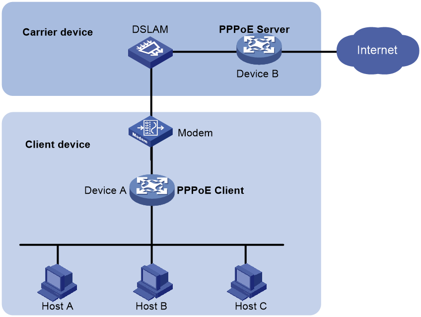
Router-initiated network structure
As shown in Figure1-1, the PPPoE session is established between devices (Device A and Device B). All hosts share one PPPoE session for data transmission without being installed with PPPoE client software. This network structure is typically used by enterprises.
Figure1-1 Router-initiated network structure
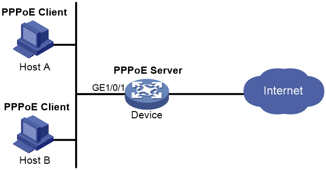
Host-initiated network structure
As shown in Figure1-2, a PPPoE session is established between each host (PPPoE client) and the carrier device (PPPoE server). The service provider assigns an account to each host for billing and control. The host must be installed with PPPoE client software.
Figure1-2 Host-initiated network structure
Configuring a PPPoE client
Operation mode
A PPPoE session can operate in one of the following modes:
· Permanent mode—A PPPoE session is established immediately when the line is physically up. This type of session remains until the physical link comes down or until the session is disconnected.
· On-demand mode—A PPPoE session is established when there is a demand for data transmission instead of when the line is physically up. It is terminated when idled for a specific period of time.
· Diagnostic mode—A PPPoE session is established immediately after the device configurations finish. The device automatically terminates the PPPoE session and then tries to re-establish a PPPoE session at a pre-configured interval. By establishing and terminating PPPoE sessions periodically, you can monitor the operating status of the PPPoE link.
The PPPoE session operating mode is determined by your configuration on the dialer interface:
· Permanent mode—Used when you set the link idle time to 0 by using the dialer timer idle command and do not configure the dialer diagnose command.
· On-demand mode—Used when you set the link idle time to a non-zero value by using the dialer timer idle command and do not configure the dialer diagnose command.
· Diagnostic mode—Used when you configure the dialer diagnose command.
PPPoE client tasks at a glance
To configure a PPPoE client, perform the following tasks:
1. Configuring a dialer interface
2. Configuring a PPPoE session
3. (Optional.) Resetting a PPPoE session
Configuring a dialer interface
About this task
Before establishing a PPPoE session, you must first create a dialer interface and configure bundle DDR on the interface. Each PPPoE session uniquely corresponds to a dialer bundle, and each dialer bundle uniquely corresponds to a dialer interface. A PPPoE session uniquely corresponds to a dialer interface.
Procedure
1. Enter system view.
system-view
2. Create a dialer group and configure a dial rule.
dialer-group group-number rule { ip | ipv6 } { deny | permit | acl { acl-number | name acl-name } }
Configure this command only when the PPPoE session operates in on-demand mode.
3. Create a dialer interface and enter its view.
interface dialer number
4. Assign an IP address to the interface.
ip address { address mask | ppp-negotiate }
By default, no IP address is configured.
5. Enable bundle DDR on the interface.
dialer bundle enable
By default, bundle DDR is disabled.
6. Associate the interface with the dial rule by associating the interface with the corresponding dialer group.
dialer-group group-number
By default, a dialer interface is not assigned to any dialer group.
Configure this command only when the PPPoE session operates in on-demand mode.
7. Configure the link-idle timeout timer.
dialer timer idle idle [ in | in-out ]
The default setting is 120 seconds.
When this timer is set to 0 seconds, the PPPoE session operates in permanent mode. Otherwise, the PPPoE session operates in on-demand mode.
8. Configure the DDR application to operate in diagnostic mode.
dialer diagnose [ interval interval ]
By default, the DDR application operates in non-diagnostic mode.
You need to execute this command only when the PPPoE session operates in diagnostic mode.
9. (Optional.) Set the auto-dial interval.
dialer timer autodial autodial-interval
The default setting is 300 seconds.
DDR starts the auto-dial timer after the link is disconnected and originates a new call when the auto-dial timer expires.
As a best practice, set a shorter auto-dial interval for DDR to soon originate a new call.
10. (Optional.) Set the MTU for the dialer interface
mtu size
By default, the MTU on a dialer interface is 1500 bytes.
The dialer interface fragments a packet that exceeds the configured MTU, and adds a 2-byte PPP header and a 6-byte PPPoE header to each fragment. You should modify the MTU of a dialer interface to make sure the total length of any fragment packet is less than the MTU of the physical interface.
Configuring a PPPoE session
1. Enter system view.
system-view
2. Enter VLAN interface view.
interface interface-type interface-number
3. Create a PPPoE session and specify a dialer bundle for the session.
pppoe-client dial-bundle-number number [ no-hostuniq ]
The number argument in this command must take the same value as the configured dialer interface number.
Resetting a PPPoE session
About this task
After you reset a PPPoE session in permanent mode, the device establishes a new PPPoE session when the autodial timer expires.
After you reset a PPPoE session in on-demand mode, the device establishes a new PPPoE session when there is a demand for data transmission.
Procedure
To reset a PPPoE session, execute the following command in user view:
reset pppoe-client { all | dial-bundle-number number }
Display and maintenance commands for PPPoE
Display and maintenance commands for PPPoE client
Execute display commands in any view and reset commands in user view.
|
Task |
Command |
|
Display summary information for a PPPoE session. |
display pppoe-client session summary [ dial-bundle-number number ] |
|
Display the protocol packet statistics for a PPPoE session. |
display pppoe-client session packet [ dial-bundle-number number ] |
|
Clear the protocol packet statistics for a PPPoE session. |
reset pppoe-client session packet [ dial-bundle-number number ] |
PPPoE configuration examples
Example: Configuring a PPPoE client in permanent mode
Network configuration
As shown in Figure1-3, Router serves as a PPPoE server. Configure AP as a PPPoE client operating in permanent mode.

Procedure
1. Configure Router as the PPPoE server:
# Configure an IP address for Virtual-Template 1 and specify an IP address for the peer.
<Router> system-view
[Router] interface virtual-template 1
[Router-Virtual-Template1] ip address 1.1.1.1 255.0.0.0
[Router-Virtual-Template1] remote address 1.1.1.2
[Router-Virtual-Template1] quit
# Enable the PPPoE server on GigabitEthernet 1/0/1, and bind the interface to Virtual-Template 1.
[Router] interface gigabitethernet 1/0/1
[Router-GigabitEthernet1/0/1] pppoe-server bind virtual-template 1
[Router-GigabitEthernet1/0/1] quit
2. Configure AP as the PPPoE client:
# Create dialer group 1 and configure a dial rule for it.
<AP> system-view
[AP] dialer-group 1 rule ip permit
# Enable bundle DDR on Dialer 1.
[AP] interface dialer 1
[AP-Dialer1] dialer bundle enable
# Associate Dialer 1 with dialer group 1.
[AP-Dialer1] dialer-group 1
# Configure Dialer 1 to obtain an IP address through PPP negotiation.
[RouterB-Dialer1] ip address ppp-negotiate
[RouterB-Dialer1] quit
# Configure a PPPoE session that corresponds to dialer bundle 1 (dialer bundle 1 corresponds to Dialer 1).
[AP] interface vlan-interface 1
[AP-Vlan-interface1] pppoe-client dial-bundle-number 1
[AP-Vlan-interface1] quit
# Configure the PPPoE session to operate in permanent mode.
[AP] interface dialer 1
[AP-Dialer1] dialer timer idle 0
# Set the DDR auto-dial interval to 60 seconds.
[AP-Dialer1] dialer timer autodial 60
[AP-Dialer1] quit
# Configure a static route.
[AP] ip route-static 1.1.1.1 255.0.0.0 dialer 1
Verifying the configuration
# Display summary information about the PPPoE session established between AP and Router (PPPoE server).
[AP] display pppoe-client session summary
Bundle ID Interface VA RemoteMAC LocalMAC State
1 1 Vlan1 VA0 00e0-1400-4300 00e0-1500-4100 SESSION
Example: Configuring a PPPoE client in on-demand mode
Network configuration
As shown in Figure1-4, Router serves as a PPPoE server. Configure AP as a PPPoE client operating in on-demand mode, and set the link idle-timeout timer to 150 seconds.

Procedure
1. Configure Router as the PPPoE server:
# Configure an IP address for Virtual-Template 1 and specify an IP address for the peer.
<Router> system-view
[Router] interface virtual-template 1
[Router-Virtual-Template1] ip address 1.1.1.1 255.0.0.0
[Router-Virtual-Template1] remote address 1.1.1.2
[Router-Virtual-Template1] quit
# Enable the PPPoE server on GigabitEthernet 1/0/1, and bind the interface to Virtual-Template 1.
[Router] interface gigabitethernet 1/0/1
[Router-GigabitEthernet1/0/1] pppoe-server bind virtual-template 1
[Router-GigabitEthernet1/0/1] quit
2. Configure AP as the PPPoE client.
# Create dialer group 1 and configure a dial rule for it.
<AP> system-view
[AP] dialer-group 1 rule ip permit
# Enable bundle DDR on Dialer 1.
[AP] interface dialer 1
[AP-Dialer1] dialer bundle enable
# Associate Dialer 1 with dialer group 1.
[AP-Dialer1] dialer-group 1
[AP-Dialer1] quit
# Configure Dialer 1 to obtain an IP address through PPP negotiation.
[AP-Dialer1] ip address ppp-negotiate
# Configure a PPPoE session that corresponds to dialer bundle 1 (dialer bundle 1 corresponds to Dialer 1).
[AP] interface vlan-interface 1
[AP-Vlan-interface1] pppoe-client dial-bundle-number 1
[AP-Vlan-interface1] quit
# Configure a static route.
[AP] ip route-static 1.1.1.1 255.0.0.0 dialer 1
# Set the link-idle timeout timer to 150 seconds.
[AP] interface dialer 1
[AP-Dialer1] dialer timer idle 150
[AP-Dialer1] quit
Verifying the configuration
# Display summary information about the PPPoE session established between AP and Router (PPPoE server).
[AP] display pppoe-client session summary
Bundle ID Interface VA RemoteMAC LocalMAC State
1 1 Vlan1 VA0 00e0-1400-4300 00e0-1500-4100 SESSION
Example: Configuring a PPPoE client in diagnostic mode
Network configuration
As shown in Figure1-5, Router serves as a PPPoE server. Configure AP as a PPPoE client operating in diagnostic mode, and set the diagnostic interval to 200 seconds.

Procedure
1. Configure Router as the PPPoE server:
# Configure an IP address for Virtual-Template 1 and specify an IP address for the peer.
<Router> system-view
[Router] interface virtual-template 1
[Router-Virtual-Template1] ip address 1.1.1.1 255.0.0.0
[Router-Virtual-Template1] remote address 1.1.1.2
[Router-Virtual-Template1] quit
# Enable the PPPoE server on GigabitEthernet 1/0/1, and bind the interface to Virtual-Template 1.
[Router] interface gigabitethernet 1/0/
[Router-GigabitEthernet1/0/1] pppoe-server bind virtual-template 1
[Router-GigabitEthernet1/0/1] quit
2. Configure AP as the PPPoE client.
# Create dialer group 1 and configure a dial rule for it.
<AP> system-view
[AP] dialer-group 1 rule ip permit
# Enable bundle DDR on Dialer 1.
[AP] interface dialer 1
[AP-Dialer1] dialer bundle enable
# Associate Dialer 1 with dialer group 1.
[AP-Dialer1] dialer-group 1
[AP-Dialer1] quit
# Configure Dialer 1 to obtain an IP address through PPP negotiation.
[AP-Dialer1] ip address ppp-negotiate
[AP-Dialer1] quit
# Configure a PPPoE session that corresponds to dialer bundle 1 (dialer bundle 1 corresponds to Dialer 1).
[AP] interface vlan-interface 1
[AP-Vlan-interface1] pppoe-client dial-bundle-number 1
[AP-Vlan-interface1] quit
# Configure the PPPoE session to operate in diagnostic mode, and set the diagnostic interval to 200 seconds.
[AP] interface dialer 1
[AP-Dialer1] dialer diagnose interval 200
# Set the DDR auto-dial interval to 10 seconds.
[AP-Dialer1] dialer timer autodial 10
Verifying the configuration
# Display summary information about the PPPoE session established between AP and Router (PPPoE server).
[AP-Dialer1] display pppoe-client session summary
Bundle ID Interface VA RemoteMAC LocalMAC State
1 1 Vlan1 VA0 00e0-1400-4300 00e0-1500-4100 SESSION
