- Table of Contents
- Related Documents
-
| Title | Size | Download |
|---|---|---|
| 01-Text | 1.52 MB |
Contents
About the SeerEngine-Campus controller
Standalone deployment restrictions
Application installation packages
Deployment procedure at a glance
Deploying SeerEngine-Campus and vDHCP
Registering and installing licenses
About the SeerEngine-Campus controller
SeerEngine-Campus is an SDN controller designed for the application-driven campus network. From a unified GUI, SeerEngine-Campus offers compressive campus network management capabilities, including zero-touch device deployment, user authentication and access control, service chaining, micro-segmentation, campus and DC interconnect, and service orchestration.
Features
SeerEngine-Campus provides the following features:
· Zero-touch device deployment—Provides fully automated underlay network deployment. Network devices can be automatically configured in plug and play mode, which frees the administrator from the tedious, error-prone tasks of node-by-node device configuration.
· User authentication—Supports various user authentication methods, including 802.1X, MAC authentication, and MAC portal authentication.
· Access control—Enforces access control on users based on their user group membership.
· Service chaining—Supports routing traffic along a chain of connected services such as firewalls and loading balancing. The chained service nodes can be third-party devices.
· Micro-segmentation—Decouples security groups from virtual networks, enabling service orchestration and deployment across management domains.
· Converged Campus & DC—Interconnects campus VPN networks and data center VPN networks.
Deployment modes
SeerEngine-Campus can be deployed only as a containerized component on Unified Platform through the Unified Platform GUI. Before deploying SeerEngine-Campus on a server, you must deploy Matrix and Unified Platform on the server first. See H3C Unified Platform Deployment Guide for the deployment procedure.
Preparing for installation
Component dependencies
You can deploy DHCP, EIA, and WSM servers in addition to the SeerEngine-Campus component. The servers are optional.
DHCP servers are required for assigning IP addresses to network devices during the zero-touch deployment process and to endpoint users requesting network access on the campus network.
You can deploy one DHCP server in standalone mode, or deploy two DHCP servers in cluster mode for high availability.
The SeerEngine-Campus network supports Microsoft DHCP servers, vDHCP servers, and Infoblox DHCP servers, of which vDHCP servers are more commonly used. The vDHCP server is provided by Unified Platform as a public service component.
To use Microsoft DHCP servers, see the related document for the deployment procedure.
To use vDHCP servers, deploy the vDHCP Server component together with SeerEngine-Campus from Unified Platform.
The EIA component manages endpoint authentication and access.
The WSM component monitors and configures wireless devices.
Standalone deployment restrictions
The following restrictions apply to standalone SeerEngine-Campus deployments:
· The remote backup function must be enabled on the standalone SeerEngine-Campus controller. This function allows the controller to back up its configuration and data to a remote server periodically (typically once in a couple of days). In case that SeerEngine-Campus redeployment is required, you can restore the most recent backup files for the system with minimal data loss.
· Failures of server hardware components such as physical drives or RAID controllers cannot be recovered by rebooting the server. The SeerEngine-Campus service will be affected or unavailable until the faulty hardware or server is replaced. However, the time required for the replacement cannot be directly evaluated since it might involve purchasing the replacement components.
Installation packages
Before the deployment, obtain the installation packages for the SeerEngine-Campus, vDHCP Server, EIA Server, and WSM Server components.
Table 1 Installation packages for SeerEngine-Campus and vDHCP Server
|
Scenario |
Component |
Component installation package |
|
Campus network |
SeerEngine-Campus |
SeerEngine_CAMPUS-version-MATRIX.zip |
|
vDHCP Server |
vDHCPS-version.zip |
|
|
EIA Server |
EIAversion.zip |
|
|
WSM Server |
WSM-version.zip |
Server requirements
Hardware requirements
SeerEngine-Campus can be deployed on a single server or on a cluster of servers. You can deploy SeerEngine-Campus on physical servers or on VMs.
The controller supports the following deployment modes:
· Deploy the controller separately.
· Deploy the controller together with SeerAnalyzer on a server.
· Deploy SeerAnalyzer separately.
If you deploy SeerAnalyzer separately and deploy the controller cluster and SeerAnalyzer cluster separately, the nodes in the SeerAnalyzer cluster operate in load balancing mode. A decrease of nodes degrades analysis performance.
Deploying the controller on physical servers
|
Item |
Requirements |
|
Drive |
The drives must be set up in RAID 1, 5, or 10 mode. · System drive: 7.2K RPM SATA/SAS HDDs, with a size of 2.4 TB or above in RAID setup. · etcd drive: 7.2K RPM SATA/SAS HDDs, with a size of 50 GB or above in RAID setup. (Installation path: /var/lib/etcd.) · Storage controller: 1GB cache, power fail protected with a supercapacitor installed. · Data drive: SSDs or SATA/SAS HDDs. As a best practice, configure a minimum of three data drives in RAID 5. |
|
NIC |
· Non-bonding mode: ¡ 1 × 1 Gbps or above Ethernet port. ¡ 2 × 10 Gbps or above Ethernet ports if SeerAnalyzer is deployed. · Bonding mode (recommended mode: mode 2 or mode 4): 2 × 10 Gbps Linux bonding interfaces. As a best practice, enable the controller and Unified Platform to share one NIC and enable the SeerAnalyzer southbound network to use a separate NIC if you deploy the controller together with SeerAnalyzer on a server. If the southbound networks can only use one NIC, the southbound networks for the controller and SeerAnalyzer can share one NIC and Unified Platform uses a separate NIC. |
|
|
IMPORTANT: In the following tables, the ratio of switches to ACs/APs is 1:3. |
Table 3 Standalone deployment of the controller (Unified Platform + vDHCP + SE + EIA + WSM, provides basic wireless management only)
|
Node settings |
Maximum resources that can be managed |
||
|
Node name |
Node quantity |
Minimum single-node requirements |
|
|
Controller |
1 |
· CPU: 24 cores, 2.0 GHz. · Memory: 144 GB. · System drive: 2.4 TB (after RAID setup). · etcd drive: 50 GB (after RAID setup). |
· 5000 online users · 1000 switches, ACs, and APs in total |
Table 4 Cluster deployment of controllers (Unified Platform + vDHCP + SE + EIA + WSM, excluding the wireless intelligent analysis feature)
|
Node settings |
Maximum resources that can be managed |
||
|
Node name |
Node quantity |
Minimum single-node requirements |
|
|
Controller |
3 |
· CPU: 24 cores, 2.0 GHz. · Memory: 128 GB. · System drive: 2.4 TB (after RAID setup). · etcd drive: 50 GB (after RAID setup). |
· 2000 online users · 400 switches, ACs, and APs in total |
|
Controller |
3 |
· CPU: 24 cores, 2.0 GHz. · Memory: 128 GB. · System drive: 2.4 TB (after RAID setup). · etcd drive: 50 GB (after RAID setup). |
· 5000 online users · 1000 switches, ACs, and APs in total |
|
Controller |
3 |
· CPU: 26 cores, 2.0 GHz. · Memory: 144 GB. · System drive: 2.4 TB (after RAID setup). · etcd drive: 50 GB (after RAID setup). |
· 10000 online users · 2000 switches, ACs, and APs in total |
|
Controller |
3 |
· CPU: 26 cores, 2.0 GHz. · Memory: 144 GB. · System drive: 2.7 TB (after RAID setup). · etcd drive: 50 GB (after RAID setup). |
· 20000 online users · 4000 switches, ACs, and APs in total |
|
Controller |
3 |
· CPU: 28 cores, 2.0 GHz. · Memory: 144 GB. · System drive: 3.0 TB (after RAID setup). · etcd drive: 50 GB (after RAID setup). |
· 40000 online users · 8000 switches, ACs, and APs in total |
|
Controller |
3 |
· CPU: 36 cores, 2.0 GHz. · Memory: 176 GB. · System drive: 3.2 TB (after RAID setup). · etcd drive: 50 GB (after RAID setup). |
· 60000 online users · 12000 switches, ACs, and APs in total |
|
Controller |
3 |
· CPU: 38 cores, 2.0 GHz. · Memory: 192 GB. · System drive: 3.4 TB (after RAID setup). · etcd drive: 50 GB (after RAID setup). |
· 100000 online users · 20000 switches, ACs, and APs in total |
|
|
IMPORTANT: · The server must support the CentOS 7.6 or later operating system. · NIC bonding allows you to bind multiple NICs to form a logical NIC for NIC redundancy, bandwidth expansion, and load balancing. NIC bonding can be configured on servers and switches. For more information about configuring NIC bonding, see H3C Unified Platform Deployment Guide. |
Deploying the controller on VMs
|
|
CAUTION: · To ensure system environment stability, make sure the CPUs, memory, and disks allocated to a VM meet the recommended capacity requirements and there are physical resources with corresponding capacity. Make sure VM resources are not overcommitted, and reserve resources for the VM. · As a best practice, install the etcd drive on a different physical drive than any other drives and make sure etcd has exclusive use of the drive where it is installed. · To deploy the controller on a VMware-managed VM, enable the network card hybrid mode and pseudo transmission on the host where the VM resides. |
You can deploy the controller on a VM, which provides the CPU, memory, and disk resources required by the controller. The supported virtualization platform and version information for a VM are the same as those for Unified Platform.
The number of vCPU cores required for deploying the controller on a VM is twice the number of CPU cores required for deploying the controller on a physical server if hyper-threading is enabled on the server where the virtualization platform is deployed. If hyper-threading is disabled, the required number of vCPU cores is the same as that of CPU cores, and memory and disks can also be configured as required for deployment on a physical server.
For configuration requirements for the memory and disks, see "Deploying the controller on physical servers."
Application installation packages
SeerEngine-Campus is deployed on Unified Platform. Table 5 shows the application installation packages required when you install Unified Platform. The following installation packages must be deployed when you deploy Unified Platform:
· common_PLAT_GlusterFS_2.0_<version>.zip (required)
· general_PLAT_portal_2.0_<version>.zip (required)
· general_PLAT_kernel_2.0_<version>.zip (required)
The following installation packages are deployed automatically when you deploy SeerEngine-Campus components:
· general_PLAT_kernel-base_2.0
· general_PLAT_network_2.0
· general_PLAT_Dashboard_2.0
· general_PLAT_widget_2.0
|
Installation package |
Description |
Remarks |
|
common_PLAT_GlusterFS_2.0_<version>.zip |
Provides local shared storage functionalities. |
Required. |
|
general_PLAT_portal_2.0_<version>.zip |
Provides portal, unified authentication, user management, service gateway, and help center functionalities. |
Required. |
|
general_PLAT_kernel_2.0_<version>.zip |
Provides access control, resource identification, license, configuration center, resource group, and log functionalities. |
Required. |
|
general_PLAT_kernel-base_2.0_<version>.zip |
Provides alarm, access parameter template, monitoring template, report, email, and SMS forwarding functionalities. |
Optional. |
|
general_PLAT_network_2.0_<version>.zip |
Provides basic network management functions, including network resources, network performance, network topology, and iCC. |
Required. |
|
general_PLAT_Dashboard_2.0_<version>.zip |
Provides the dashboard framework. |
Required. |
|
general_PLAT_widget_2.0_<version>.zip |
Provides dashboard widget management. |
Required. |
|
general_PLAT_websocket_2.0_<version>.zip |
Provides the southbound Websocket function. |
Required. |
|
general_PLAT_cmdb_2.0_<version>.zip |
Provides database configuration and management. |
Optional. |
|
general_PLAT_kernel_region_2.0_<version>.zip |
Provides hierarchical management functions. |
Optional. |
|
general_PLAT_netconf_1.0_<version>.zip |
Provides NETCONF channel services and validity check services about NETCONF configuration. |
Optional. |
Deployment procedure at a glance
Table 6 Deployment procedure
|
Task |
Procedure |
Remarks |
|
Install the H3Linux operating system |
Install the H3Linux operating system on each server. |
See H3C Unified Platform Deployment Guide. |
|
Deploy Unified Platform |
· Deploy Matrix. · Configure Matrix cluster parameters. · Deploy the Matrix cluster. · Deploy Unified Platform. |
See H3C Unified Platform Deployment Guide. |
|
Deploy the SeerEngine-Campus, vDHCP Server, EIA, and WSM components |
Deploy the required components. |
See "Deploying the controller." |
Client requirements
You can access Unified Platform from a Web browser without installing any client. For more information, see H3C Unified Platform Deployment Guide.
Pre-installation checklist
Table 7 Pre-installation checklist
|
Item |
Requirements |
|
|
Server |
Hardware |
· The CPUs, memory, drives, and NICs meet the requirements. · The server supports Unified Platform. |
|
Software |
The system time settings are configured correctly. As a best practice, configure NTP for time synchronization and make sure the devices synchronize to the same clock source. |
|
|
Client |
You can access Unified Platform from a Web browser without installing any client. As a best practice, use Google Chrome 55 or a later version. |
|
Deploying the controller
|
|
IMPORTANT: · The controller runs on Unified Platform. You can deploy, upgrade, and uninstall it only on Unified Platform. · Before deploying the controller, make sure the required applications have been deployed. |
Preparing for deployment
Enabling the NICs
SeerEngine-Campus and vDHCP Server run in containerized mode on a physical server and require NICs for processing their service traffic. You can use the NIC assigned to Unified Platform for this purpose, or enable new NICs. The latter is recommended to ensure network stability. To use bonding NICs, double the number of enabled NICs.
To enable a NIC:
1. Log in to the server on which Unified Platform is deployed remotely and edit the NIC configuration file. This example edits the configuration file for NIC ens192.
a. Open the NIC configuration file.
[root@UC01 /]# vi /etc/sysconfig/network-scripts/ifcfg-ens192
b. Set the BOOTPROTO field to none to remove NIC startup protocols, and set the ONBOOT field to yes to enable automatic NIC connection at server startup.
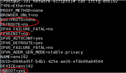
2. Restart the NIC.
[root@UC01 /]# ifdown ens192
[root@UC01 /]# ifup ens192
3. Use the ifconfig command to display network information and verify that the NIC is in up state.
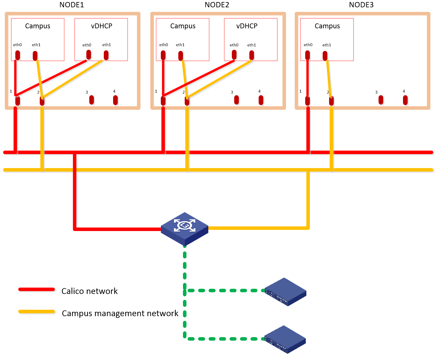
Planning the networks
The campus scenario uses the Layer 3 network scheme, where the controller NIC IP and the two IP addresses of the device are on different subnets. In this network scheme, device in multiple fabrics can come online automatically. For the controller to provide automated underlay network deployment function, you must configure DHCP relay agent on the Layer 3 gateway device between the server that hosts the controller and the spine and leaf devices.
The solution deploys the following networks:
· Calico network—Network for containers to communicate with each other. The Calico network uses the IP address pool (177.177.0.0 by default) specified at Unified Platform cluster deployment. You do not need to configure addresses for the Calico network at component deployment. The network can share the same NIC as the MACVLAN network.
· MACVLAN network—Management network for the SeerEngine-Campus and the vDHCP components. You must plan network address pools for the MACVLAN network before deploying a component.
As a best practice, use Table 8 to calculate the number of required IP addresses in the subnet assigned to the MACVLAN network. For example, if the SeerEngine-Campus cluster has three members and the vDHCP cluster has two members, the required number of IP addresses is: (1*3+1) + (1*2+1)=7.
Table 8 IP address planning for the MACVLAN network
|
Component name |
Max cluster members |
Default cluster members |
Required addresses for SeerEngine-Campus or vDHCP |
|
SeerEngine-Campus |
32 |
3 |
1*Member quantity + 1 The additional address is reserved as the cluster IP address. |
|
vDHCP |
2 |
2 |
Deploying SeerEngine-Campus and vDHCP
1. Log in to Unified Platform. See H3C Unified Platform Deployment Guide for the operation procedure.
2. On the top navigation bar, click System.
3. Click Settings.
4. Click Install.
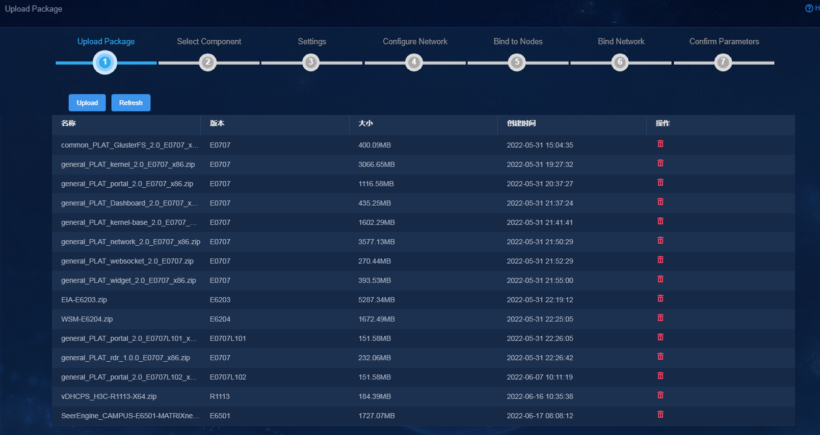
5. Click Upload to upload the SeerEngine-Campus, vDHCP Server, EIA, and WSM packages to the system.
Figure 2 Upload Package page
6. Select components to deploy, and then click Next.
¡ Campus Network—Specify the SeerEngine-Campus version, and select Converged EIA.
¡ The End User Intelligent Access—Specify the EIA version.
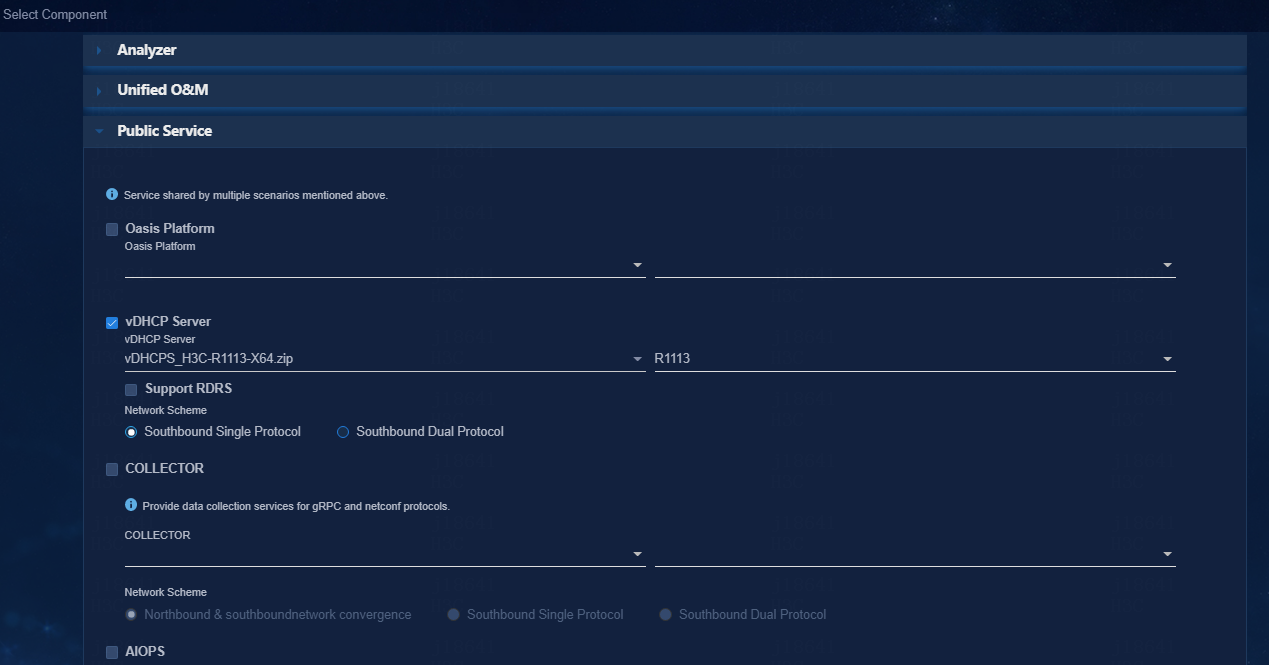
¡ Public Service—Specify the vDHCP Server version. Unified Platform will deploy the vDHCP server in a two-node cluster automatically.
Figure 3 Selecting components (1)
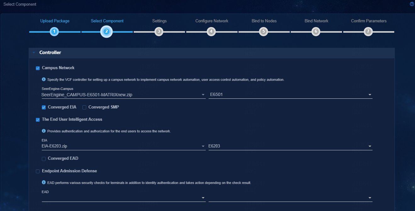
Figure 4 Selecting components (2)
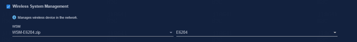
7. On the Select Component page, select Wireless System Management. Select the WSM Server software package to be uploaded. The WSM component is optional. To run wireless services, you must install the WSM component.
Figure 5 Selecting components (3)
8. Retain default parameter settings and click Next.
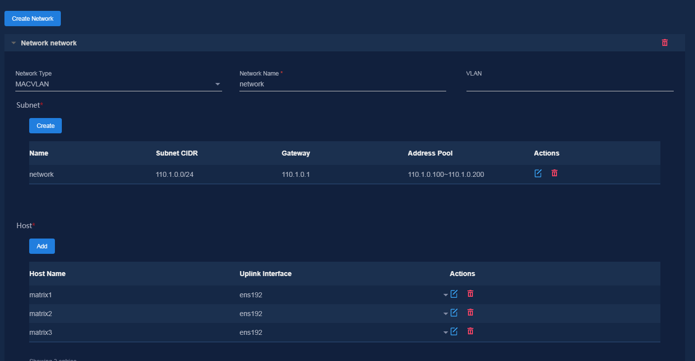
9. Specify network information, create subnets, configure host information, and then click Next.
The controller uses the management network to manage southbound devices. Configure the following parameters as needed:
¡ VLAN—If multiple networks use the same uplink interface on a host, configure VLANs to isolate the networks. By default, no VLAN is specified.
¡ Subnet CIDR, Gateway, Address Pool—The platform uses the subnet and address pool to assign IP addresses to components and uses the gateway as the default gateway for containers.
¡ Uplink Interface—Hosts use their uplink interface for providing services to SeerEngine-Campus and vDHCP Server containers.
Figure 6 Network Configuration
|
|
NOTE: Address pool settings cannot be edited once applied. As a best practice, configure a minimum of 32 IP addresses in each address pool. |
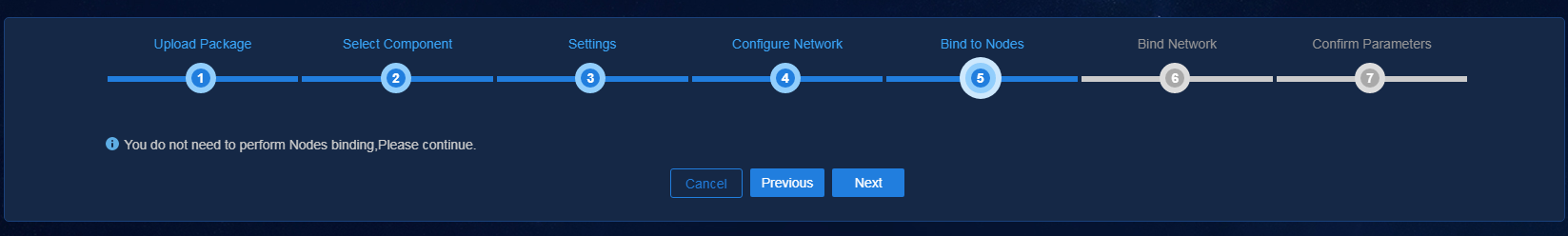
10. Skip node binding and click Next.
Figure 7 Binding to nodes
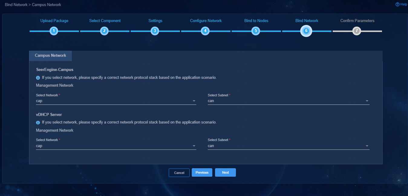
11. Bind networks and subnets to SeerEngine-Campus and vDHCP Server, and then click Next.
Figure 8 Binding networks and subnets to components
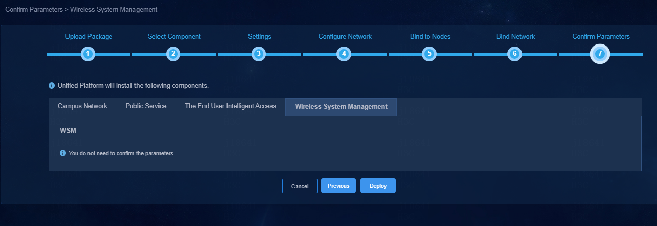
12. Confirm parameters and then click Deploy.
¡ Cluster IP—The platform sets the cluster IP address for each component based on address pool configuration. To edit the cluster IP address for a component, click Reset. Make sure the manually specified address is within the specified subnet for the component.
¡ VRRP Group Number—Specify a VRRP group number for vDHCP, in the range of 1 to 255. Specify different VRRP group numbers for vDHCP servers in the same network.
¡ EIA parameters—The EIA component uses the northbound service virtual IP as the system address. You do not need to confirm EIA parameters.
¡ WSM parameters—You do not need to confirm WSM parameters.
Figure 9 Confirming campus network parameters
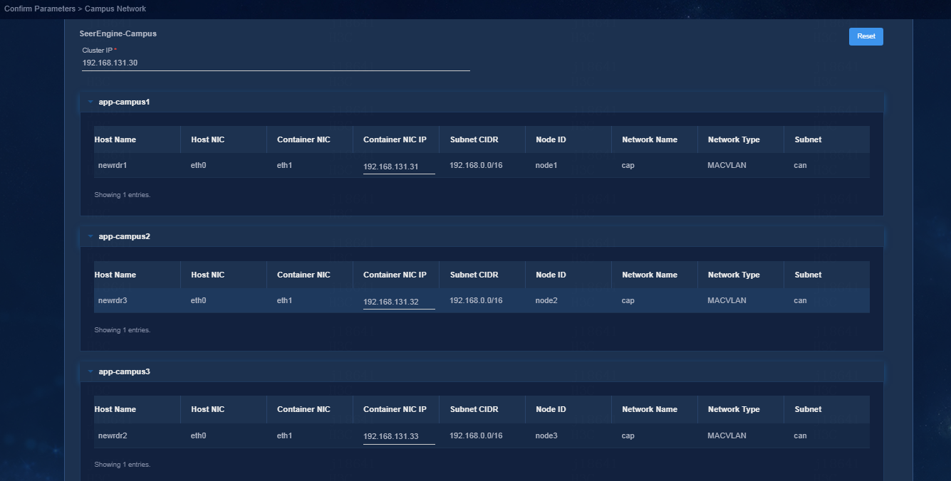
Figure 10 Confirming vDHCP server parameters
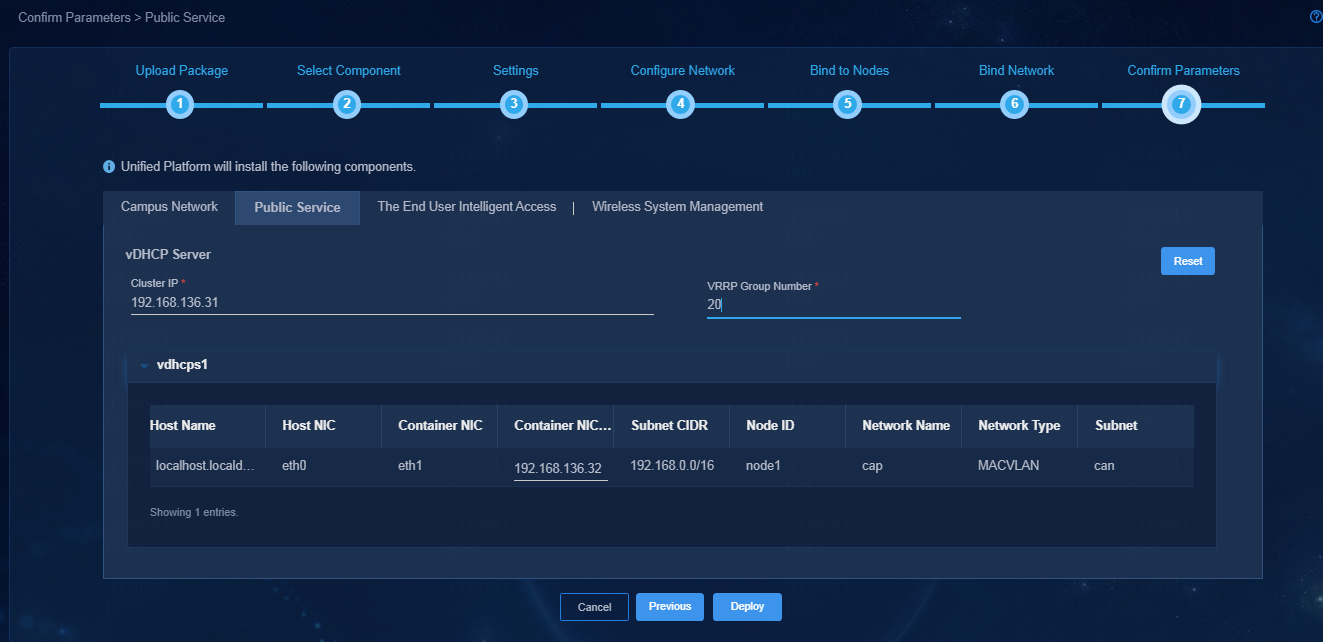
Figure 11 Confirming EIA parameters
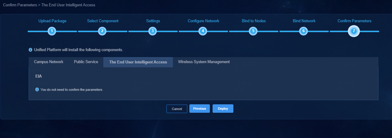
Figure 12 Confirming WSM parameters
13. To view detailed
information about a component, click
the ![]() icon to the left of a component, and then click
icon to the left of a component, and then click ![]() in
the Actions column for that component.
in
the Actions column for that component.
Figure 13 Expanding component information
14. Enter the Unified Platform login address in your browser and then press Enter. The default login address is http://ip_address:30000/central/index.html. ip_address represents the virtual IP for the northbound service of Unified Platform. 30000 represents the port number.
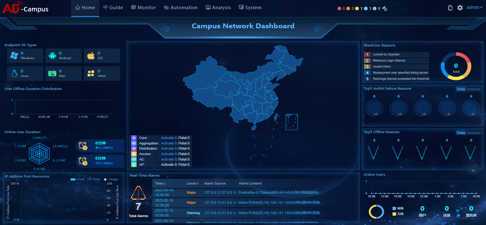
15. Click Automation on the top navigation bar and then select Campus Network from the left navigation pane to configure the campus network.
Figure 14 SeerEngine-Campus controller home page
Registering and installing licenses
After you install the controller, you can use its complete features and functions for a 90-day trial period. After the trial period expires, you must get the controller licensed. For how to license the vDHCP server, see the user guide for the vDHCP server.
Installing the activation file on the license server
For the activation file request and installation procedure, see H3C Software Products Remote Licensing Guide.
Obtaining licenses
1. Log in to the SeerEngine-Campus controller.
2. From the navigation pane, select System > License.
3. Configure the parameters for the license server as described in Table 9.
Table 9 License server parameters
|
Item |
Description |
|
IP address |
Specify the IP address configured on the license server used for internal communication in the cluster. |
|
Port number |
Specify the service port number of the license server. The default value is 5555. |
|
Username |
Specify the client username configured on the license server. |
|
Password |
Specify the client password configured on the license server. |
4. Click Connect to connect the controller to the license server.
The controller will automatically obtain licensing information after connecting to the license server.
Upgrading the controller
|
|
CAUTION: The upgrade might cause service interruption. Be cautious when you perform this operation. |
The controller can be upgraded on Unified Platform with the configuration retained.
To upgrade the controller:
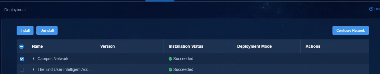
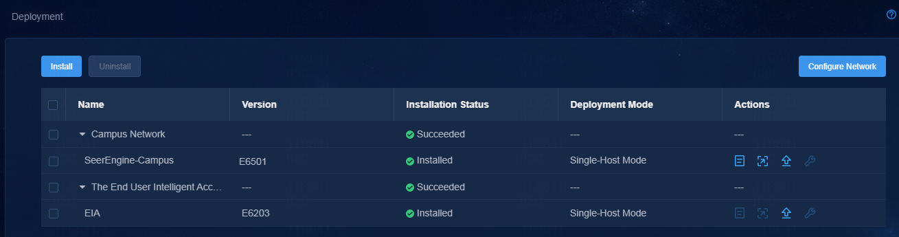
1. Log in to Unified Platform. Click System > Deployment.
Figure 15 Deployment page
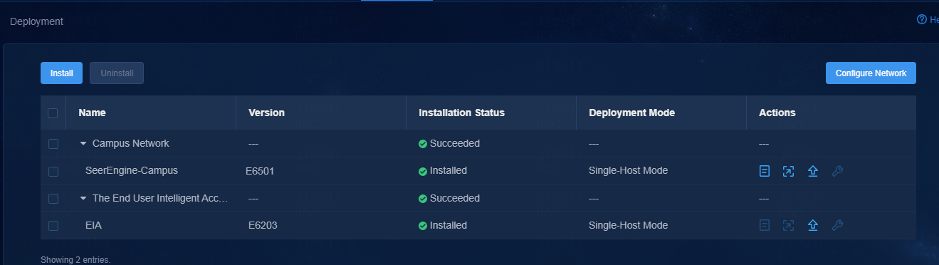
2. Click the left chevron button ![]() for the controller to
expand controller information, and then click the upgrade icon
for the controller to
expand controller information, and then click the upgrade icon ![]() .
.
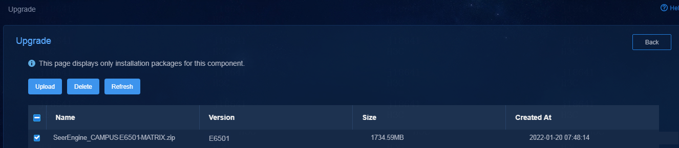
3. Upload and select the installation package.
Figure 16 Upgrading the controller
4. If the upgrade fails, click Roll Back to roll back to the previous version.
Uninstalling the controller
1. Log in to Unified Platform. Click System > Deployment.
2. Click the ![]() icon to the left of the controller name and then
click Uninstall.
icon to the left of the controller name and then
click Uninstall.
Figure 17 Uninstalling the controller