- Table of Contents
- Related Documents
-
| Title | Size | Download |
|---|---|---|
| 01-Text | 2.62 MB |
Contents
General safety recommendations
Examining the installation site
Mounting the firewall on a workbench
Installing the firewall in a standard 19-inch rack
Grounding the firewall with a grounding strip
Grounding the firewall with the grounding terminal on the rack
Installing optional components
(Optional) Installing a Micro SD card
(Optional) Installing a 4G module
(Optional) Installing a SIM card
Connecting a copper Ethernet port
Connecting the power adapter or power cord
Connecting the power adapter for an F100-C-A1 or F100-C-A2 firewall
Starting the firewall and observing the initial startup conditions
Logging in from the Web interface
Logging in from the console port
4 Replacing a transceiver module
5 Hardware management and maintenance
Displaying detailed information about the firewall
Displaying software and hardware version information for the firewall
Displaying electrical label information for the firewall
Displaying the CPU usage of the firewall
Displaying the memory usage of the firewall
Displaying the operational status of the power module
Displaying the operational statistics about the firewall
Configuration terminal display issue
7 Appendix A Chassis views and technical specifications
F100-C-A3-W/F100-C-A5-W/F100-C-A6-WL
Making an Ethernet twisted pair cable
1 Preparing for installation
The H3C SecPath F100-C-A firewall series include the following models:
· F100-C-A1
· F100-C-A2
· F100-C-A3
· F100-C-A3-W
· F100-C-A5
· F100-C-A5-W
· F100-C-A6-WL
Safety recommendations
To avoid any equipment damage or bodily injury, read the following safety recommendations before installation. Note that the recommendations do not cover every possible hazardous condition.
Safety symbols
When reading this document, note the following symbols:
![]() WARNING means an alert that calls attention to important information that if
not understood or followed can result in personal injury.
WARNING means an alert that calls attention to important information that if
not understood or followed can result in personal injury.
![]() CAUTION means an alert that calls attention to important information that if
not understood or followed can result in data loss, data corruption, or damage
to hardware or software.
CAUTION means an alert that calls attention to important information that if
not understood or followed can result in data loss, data corruption, or damage
to hardware or software.
General safety recommendations
· Make sure the installation position is flat, vibration-free, and away from electromagnetic interferences. ESD and anti-slip measures are in place.
· Do not place the firewall on an unstable case or desk. The firewall might be severely damaged in case of a fall.
· Keep the chassis and installation tools away from walk areas.
· Keep the chassis clean and dust-free.
· Do not place the firewall near water or in a damp environment. Prevent water or moisture from entering the firewall chassis.
· Pay attention to the safety symbols on the package and handle the device accordingly.
Figure1-1 Packing symbols
|
Symbol |
Description |
|
|
The devices shall not be vertically stacked beyond the specified number. |
|
|
Place the device with the arrows up. |
|
|
The device is fragile. Handle it with care. |
|
|
Keep the device from humidity, rains, and wet floor. |


· When stacking devices, place the heavier and larger ones at the bottom. Make sure the devices are stacked evenly.
· Ensure good ventilation of the equipment room and keep the air inlet and outlet vents of the firewall free of obstruction.
· Make sure the operating voltage is in the required range.
· Use a screwdriver, rather than your fingers, to fasten screws.
· Take away the packaging materials and installation tools after installation.
Electrical safety
· Carefully examine your work area for possible hazards such as moist floors, ungrounded power extension cables, and missing safety grounds.
· Locate the emergency power-off switch in the room before installation. Shut the power off at once in case accident occurs.
· Do not work alone when the firewall has power.
· Always verify that the power has been disconnected when you perform operations that require the device to be powered off.
Handling safety
When you move the firewall, follow these guidelines:
· Move and unpack the firewall carefully to avoid firewall damage.
· Unpack the firewall at least half an hour and power on the firewall at least two hours after you move it from a place below 0°C (32°F) to the equipment room. This prevents condensation and even damage to the firewall.
· Use a safety hand truck when you move multiple firewalls.
· Before you move the firewall, remove all cables and mounting brackets.
· For long-distance transportation, remove all removable components, such as 4G modules and 4G antennas, and package them separately, and install the filler panels supplied with the firewall. For short-distance transportation, make sure all removable components are securely seated in the slots and the screws are fastened.
· When you move or lift the firewall chassis, support the bottom of the chassis, rather than holding any removable component.
· Make sure the accessories of the firewall are not lost or damaged during firewall moving.
Examining the installation site
The firewall can only be used indoors. To make sure the firewall operates correctly and to prolong its service lifetime, the installation site must meet the following requirements.
Weight support
Make sure the floor can support the total weight of the chassis and accessories. For the chassis weight, see "Dimensions and weights."
Temperature and humidity
Maintain appropriate temperature and humidity in the equipment room.
· Lasting high relative humidity can cause poor insulation, electricity leakage, mechanical property change of materials, and metal corrosion.
· Lasting low relative humidity can cause washer contraction and ESD and bring problems including loose captive screws and circuit failure.
· High temperature can accelerate the aging of insulation materials and significantly lower the reliability and lifespan of the firewall.
For the temperature and humidity requirements of the firewall, see Table1-1.
Table1-1 Temperature/humidity requirements
|
Item |
Specification |
|
Ambient temperature |
· Operating: 0°C to 45°C (32°F to 113°F) · Storage: –40°C to +70°C (–40°F to +158°F) |
|
Ambient humidity |
5% RH to 95% RH, noncondensing |
Cleanliness
Dust buildup on the chassis might result in electrostatic adsorption, which causes poor contact of metal components and contact points, especially when indoor relative humidity is low. In the worst case, electrostatic adsorption can cause communication failure.
Table1-2 Dust concentration limit in the equipment room
|
Substance |
Concentration limit (particles/m3) |
|
Dust particles |
≤ 3 × 10⁴ (No visible dust on desk in three days) |
|
NOTE: Dust particle diameter ≥ 5 µm |
|
The equipment room must also meet strict limits on salts, acids, and sulfides to eliminate corrosion and premature aging of components, as shown in Table1-3.
Table1-3 Harmful gas limits in an equipment room
|
Gas |
Max. (mg/m3) |
|
SO2 |
0.2 |
|
H2S |
0.006 |
|
NH3 |
0.05 |
|
Cl2 |
0.01 |
|
NO2 |
0.04 |
Cooling system
The firewall uses natural cooling. For adequate cooling of the firewall, follow these guidelines:
· Reserve a minimum clearance of 100 mm (3.94 in) around the outlet air vents.
· Make sure the installation site has a good cooling system.
ESD prevention
To prevent electrostatic discharge (ESD), follow these guidelines:
· Make sure the firewall, the workbench, and the rack are reliably grounded.
· Take dust-proof measures for the equipment room. For more information, see "Cleanliness."
· Maintain the humidity and temperature at an acceptable level. For more information, see "Temperature and humidity."
· Wear ESD clothing and an ESD wrist strap or ESD gloves and remove any conductive objects before your operation with the firewall.
· Always wear ESD clothing, ESD gloves, and an ESD wrist strap.
EMI
All electromagnetic interference (EMI) sources, from outside or inside of the firewall and application system, adversely affect the firewall in the following ways:
· A conduction pattern of capacitance coupling.
· Inductance coupling.
· Electromagnetic wave radiation.
· Common impedance (including the grounding system) coupling.
To prevent EMI, use the following guidelines:
· If AC power is used, use a single-phase three-wire power receptacle with protection earth (PE) to filter interference from the power grid.
· Keep the firewall far away from radio transmitting stations, radar stations, and high-frequency devices.
· Use electromagnetic shielding, for example, shielded interface cables, when necessary.
· To prevent signal ports from getting damaged by overvoltage or overcurrent caused by lightning strikes, route interface cables only indoors. If part of the network cable of an Ethernet port must be routed outdoors, connect a lightning arrester to the cable before you plug the cable into the port.
Lightning protection
To protect the firewall from lightning better, follow these guidelines:
· Make sure the grounding cable of the chassis is reliably grounded.
· Make sure the grounding terminal of the AC power receptacle is reliably grounded.
· If an AC power cord is routed from outdoors for connecting to the device, connect the power cord first to a power lightning arrester before connecting it to the power receptacle on the device.
· If a network cable is routed from outdoors for connecting to an Ethernet port on the firewall, connect the network cable first to a network port lightning arrester before connecting it to the port.
|
|
IMPORTANT: No network port lightning arrester or AC power lightning arrester is provided with the device. Prepare them as required. For the technical specifications and installation instructions for the lightning protectors, see the documents shipped with them. |
Power supply
Verify that the power system at the installation site meets the firewall power requirements, including the power input method and rated input voltage. For more information, see "Appendix A Chassis views and technical specifications."
Installation tools
No installation tools are provided with the firewall. Prepare them yourself as required.
Table1-4 Installation tools
|
|
|
|
|
|
Flat-head screwdriver |
Phillips screwdriver |
Needle-nose pliers |
Marker |
|
|
|
|
|
|
Diagonal pliers |
ESD wrist strap |
Wire stripper |
Crimping tool |
|
|
|
|
|
|
Hammer drill |
Rubber hammer |
|
|

Installation accessories
Table1-5 Installation accessories
|
|
|
|
|
|
Mounting bracket |
M4 mounting bracket screw |
M6 rack screw |
Cage nut |
|
|
|
|
|
|
Screw anchor and screw |
F100-C-A6/F100-C-A6-WL 4G antenna |
F100-C-A3-W/F100-C-A5-W/F100-C-A6-WL Wi-Fi antenna |
Rubber feet |
|
|
|
|
|
|
Grounding cable |
Power cord retainer clip |
Power cord for the F100-C-A3/F100-C-A5/ F100-C-A3-W/F100-C-A5-W/F100-C-A6/F100-C-A6-WL |
Power adapter for the F100-C-A1/F100-C-A2 |
|
|
|
|
|
|
Console cable |
|
|
|


Pre-installation checklist
Table1-6 Checklist before installation
|
Item |
Requirements |
Result |
|
|
Installation site |
Ventilation |
· There is a minimum clearance of 100 mm (3.94 in) around the inlet and outlet air vents for heat dissipation of the firewall chassis. · A good ventilation system is available at the installation site. |
|
|
Ambient temperature |
· Operating: 0°C to 45°C (32°F to 113°F) · Storage: –40°C to +70°C (–40°F to +158°F) |
|
|
|
Ambient humidity |
5% RH to 95% RH, noncondensing |
|
|
|
Cleanness |
· Dust concentration ≤ 3 × 10⁴ particles/m3 · No dust on desk within three days |
|
|
|
ESD prevention |
· The equipment, workbench, and rack are reliably grounded. · The equipment room is dust-proof. · The humidity and temperature are at an acceptable level. · Wear an ESD wrist strap and make sure it makes good skin contact and is reliably grounded when installing removable components. |
|
|
|
EMI prevention |
· Take effective measures to protect the power system from the power grid system. · Separate the protection ground of the firewall from the grounding device or lightning protection grounding device as far as possible. · Keep the firewall far away from radio stations, radar and high-frequency devices working in high current. · Use electromagnetic shielding when necessary. |
|
|
|
Lightning protection |
· The grounding cable of the chassis is reliably grounded. · The grounding terminal of the AC power receptacle is reliably grounded. · (Optional.) A power lightning arrester is installed. |
|
|
|
Power supply |
Verify that the power system at the installation site meets the firewall power requirements, including the power input method and rated input voltage. |
|
|
|
Rack-mounting requirements |
· Make sure the cabinet is equipped with a good ventilation system. · The rack is sturdy enough to support the weight of the firewall and installation accessories. · The size of the rack is appropriate for the firewall. · The front and rear of the rack are a minimum of 0.8 m (31.50 in) away from walls or other devices. |
|
|
|
Safety precautions |
· The firewall is far away from any moist area and heat source. · The emergency power switch in the equipment room is located. |
|
|
|
Tools and accessories |
· Installation accessories supplied with the firewall · User-supplied tools |
|
|
|
Reference |
· Documents shipped with the firewall · Online documents |
|
|
2 Installing the firewall
|
|
WARNING! Keep the tamper-proof seal on a mounting screw on the chassis cover intact, and if you want to open the chassis, contact H3C for permission. Otherwise, H3C shall not be liable for any consequence. |
The installation procedure is the same for the H3C SecPath F100-C-A series firewalls. This document uses the F100-C-A1 firewall as an example.
The figures in the following procedures are for illustration only.
To install an F100-C-A1 firewall:
Before installation, make sure all requirements on the checklist are met and the firewall is powered off.
2. Mounting the firewall on a workbench
3. Mount the firewall on a wall
4. Installing the firewall in a standard 19-inch rack
7. Installing optional components
¡ (Optional) Installing a Micro SD card
¡ (Optional) Installing a 4G module
¡ (Optional) Installing a SIM card
9. Connecting the power adapter or power cord
|
|
CAUTION: Wear an ESD wrist strap during the installation process, and make sure the wrist strap makes good skin contact and is reliably grounded. |
Mounting the firewall on a workbench
|
|
IMPORTANT: · Ensure good ventilation and a minimum clearance of 100 mm (3.94 in) around the chassis for heat dissipation. · Avoid placing heavy objects on the firewall. · To stack firewalls, make sure a minimum vertical distance of 15 mm (0.59 in) is available between two adjacent firewalls. |
If a standard 19-inch rack is not available, you can place the firewall on a workbench.
To mount the firewall on a workbench:
1. Verify that the workbench is sturdy and reliably grounded.
2. Place the firewall upside down on the workbench and clean the four round holes in the chassis bottom with a dry cloth.
3. Attach the four rubber feet to the round holes in the chassis bottom.
4. Place the firewall with upside up on the workbench.
Figure2-2 Mounting the firewall on a workbench
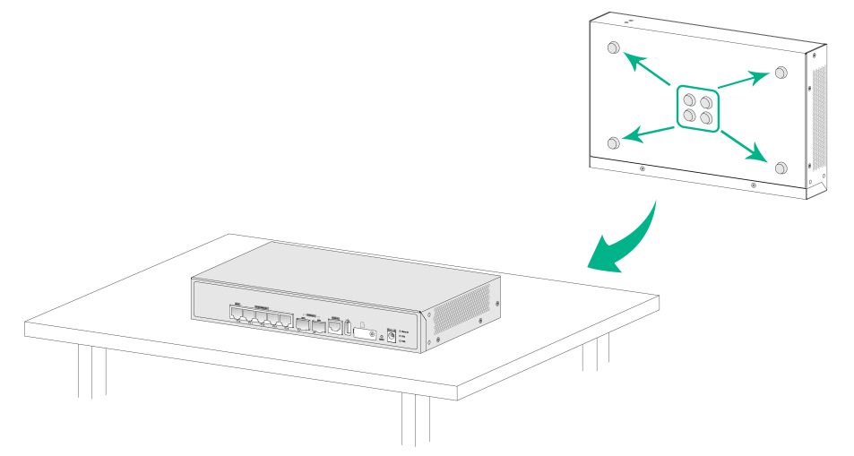
Mount the firewall on a wall
Only the F100-C-A3, F100-C-A3-W, F100-C-A5, F100-C-A5-W, F100-C-A6, and F100-C-A6-WL firewalls support wall mounting.
To mount the firewall on a wall:
1. Unpack the firewall and accessories.
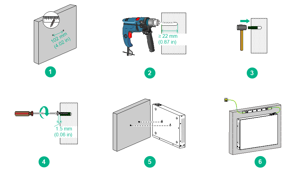
2. Mark two installation holes spaced 102 mm (4.02 in) apart on the wall.
3. Drill holes with a diameter of 6 mm (0.24 in) and a depth of 22 mm (0.87 in) at the marked locations.
4. Hammer a screw anchor into each hole and drive a screw into each screw anchor, leaving 1.5 mm (0.06 in) of the screw exposed to hang the firewall on.
Make sure the screw anchors and screws are secured in place.
5. Hold the firewall with its front panel facing downwards, align the installation holes on the firewall with the screws on the wall, and set the holes over the screws.
6. Verify that the firewall is securely mounted on the wall. Do not let go of your hands from the firewall until you are sure of the secure mounting of the firewall.
7. Connect the firewall to the grounding facility of the building.
Figure2-3 Mounting the firewall on a wall
Installing the firewall in a standard 19-inch rack
|
|
WARNING! To avoid bodily injury and device damage, use a minimum of two persons to rack-mount the firewall. |
|
CAUTION: · For adequate heat dissipation, ensure a distance of 1U (44.45 mm, or 1.75 in) between the chassis and other devices in the rack. · The firewall is heavy. Both mounting brackets and shelf are required to support the weight of the chassis. |
To install the firewall in a standard 19-inch rack:
1. Unpack the firewall and accessories.
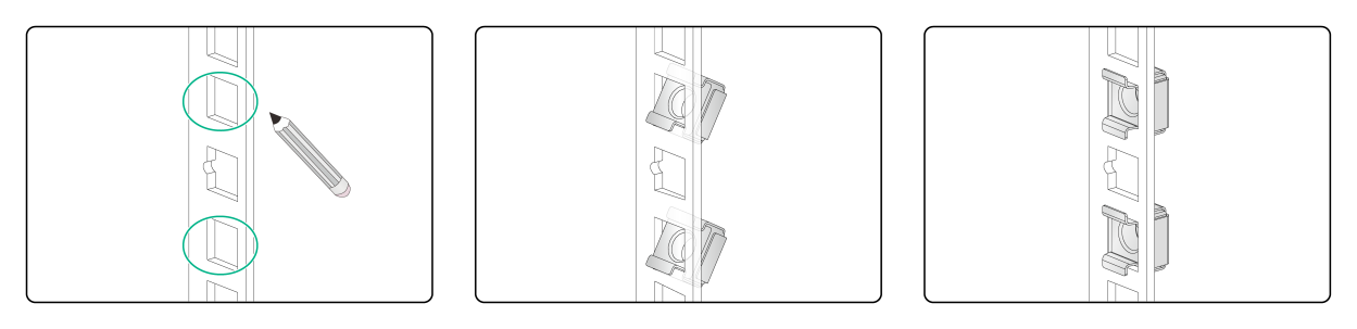
2. Mark the cage nut installation positions on the front rack posts by using the mounting brackets.
3. Install cage nuts.
Figure2-4 Installing cage nuts
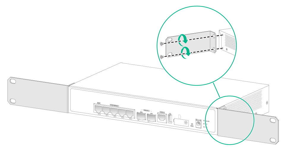
4. Use the provided M4 mounting bracket screws to secure the mounting brackets to both sides of the firewall.
Figure2-5 Securing mounting brackets to the firewall
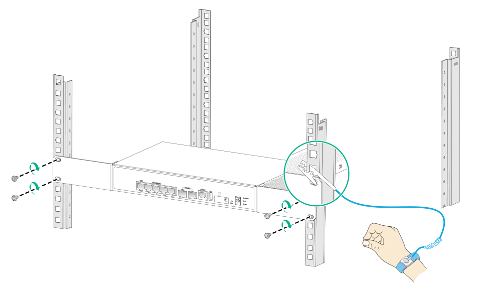
5. Mount the firewall in the rack. Use M6 rack screws to secure the mounting brackets to the front rack posts.
Figure2-6 Mounting the firewall in the rack
Grounding the firewall
|
|
WARNING! · Correctly connecting the firewall grounding cable is crucial to lightning protection and EMI protection. · Do not connect the firewall grounding cable to a fire main or lightning rod. |
If you mount the firewall on a wall, connect the firewall to the grounding facility of the building. For other installation methods, you can ground the firewall in one of the following ways, depending on the grounding conditions available at the installation site.
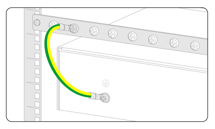
Grounding the firewall with a grounding strip
If a grounding strip is available at the installation site, connect the grounding cable through the grounding strip.
To connect the grounding cable:
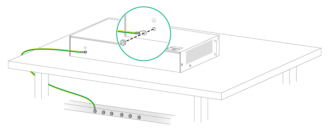
1. Remove the grounding screw from the firewall chassis.
2. Attach the grounding screw to the ring terminal of the grounding cable.
3. Use a Phillips screwdriver to fasten the grounding screw into the grounding hole on the firewall.
4. Remove the hex nut from the grounding strip.
5. Use needle-nose pliers to bend a hook at the other end of the grounding cable. Attach the hook to the grounding point, and secure the hook with a screw.
Figure2-7 Grounding the firewall with a grounding strip
Grounding the firewall with the grounding terminal on the rack
1. Remove the grounding screw from the firewall chassis.
2. Attach the grounding screw to the ring terminal of the grounding cable.
3. Use a Phillips screwdriver to fasten the grounding screw into the grounding hole on the firewall.
4. Remove the grounding screw from the grounding point on the rack.
5. Use needle-nose pliers to bend a hook at the other end of the grounding cable. Attach the hook to the grounding point, and secure the hook with the screw.
Figure2-8 Grounding the firewall with the grounding terminal on the rack
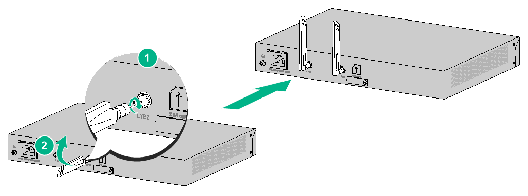
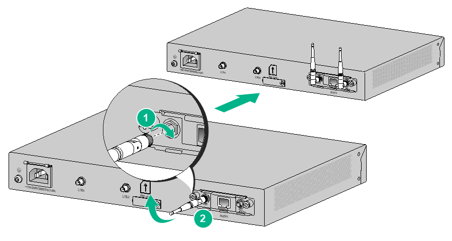
Installing a 4G antenna
The F100-C-A6 and F100-C-A6-WL firewalls each have a built-in 4G module. To use the 4G feature on the F100-C-A6 and F100-C-A6-WL firewall, install a 4G antenna for it.
To use the 4G feature, you must install a SIM card on the firewall. For how to install a SIM card, see "(Optional) Installing a SIM card."
To install a 4G antenna:
1. Face the rear panel of the firewall.
2. Attach the 4G antenna to the firewall and fasten it and then fold the antenna to an angle of 90 degrees.
Figure2-9 Installing a 4G antenna
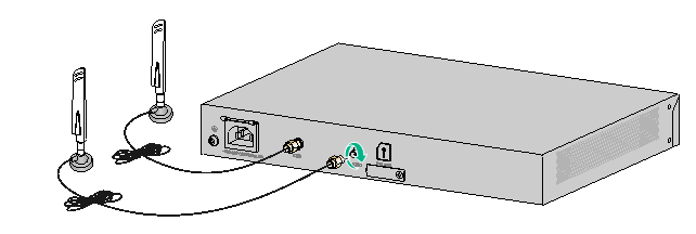
3. (Optional.) If the 4G signal is not strong at the device location, you can use an extension cable for the antenna and place the 4G antenna in a location where the 4G signal is strong.
No extension cable is provided with the firewall. Purchase one as required. To avoid extension cable incompatibility with the firewall, contact the H3C sales personnel or sales agents for compatible extension cables.
Figure2-10 Installing an extension cable for a 4G antenna
Installing optional components
(Optional) Installing a Micro SD card
|
|
CAUTION: To avoid damaging the Micro SD card slot, do not use excessive force when you install a Micro SD card. |
Only the F100-C-A1 and F100-C-A2 firewalls support Micro SD cards.
No Micro SD card is provided with the firewall. Purchase one as required.
To install a Micro SD card:
1. Face the front panel of the firewall. Use a Phillips screwdriver to remove the screw on the Micro SD card slot cover and take off the cover.
2. Push the Micro SD card into the slot until it clicks into place.
3. Reinstall the cover and fasten the screw on the cover.
Figure2-11 Installing a Micro SD card
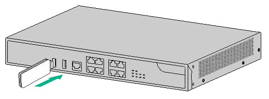
(Optional) Installing a 4G module
Only the F100-C-A3, F100-C-A3-W, F100-C-A5, F100-C-A5-W, F100-C-A6, and F100-C-A6-WL firewalls support 4G modules.
No 4G module is provided with the firewall. Purchase one as required. To avoid 4G module incompatibility with the firewall, contact the H3C sales personnel or sales agents for the compatible 4G modules.
4G modules are plug and play. To use a 4G module, insert it into a USB port on the firewall.
To install a 4G module:
1. Face the front panel of the firewall.
2. Insert the 4G module into a USB port on the firewall.
Figure2-12 Installing a 4G module
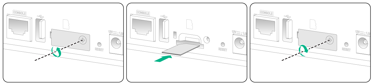
(Optional) Installing a SIM card
|
|
CAUTION: · Before installing or removing a SIM card, make sure the firewall is powered off. · Do not touch the components on the SIM card. · To avoid damaging the SIM card slot, do not use excessive force when installing a SIM card. |
Only the F100-C-A6 and F100-C-A6-WL firewalls support SIM cards.
No SIM card is provided with the firewall. Purchase one as required.
To install a SIM card:
1. Face the rear panel of the firewall. Use a Phillips screwdriver to remove the screw on the SIM card slot cover and take off the cover.
2. Insert the SIM card into the SIM card slot along the guide rails until it clicks into place.
3. Reinstall the cover and fasten the screw on the cover.
Figure2-13 Installing a SIM card

If you want to replace the SIM card, perform the following steps:
1. Remove the cover form the SIM card slot.
2. Push the SIM card inward until it pops out. Then remove the SIM card from the slot.
3. Install a new SIM card.
If you are not to install a SIM card, reinstall the cover over the empty SIM card slot to avoid ESD damage caused by dust or object intrusions.
Installing a Wi-Fi antenna
Only the F100-C-A3-W, F100-C-A5-W, and F100-C-A6-WL firewalls support Wi-Fi antennas.
No Wi-Fi antenna is provided with the firewall. Purchase one as required.
To install a Wi-Fi antenna:
1. Face the rear panel of the firewall.
2. Attach the Wi-Fi antenna to the firewall and fold the antenna to an angle of 90 degrees.
Figure2-14 Installing a Wi-Fi antenna
Connecting Ethernet cables
Connecting a copper Ethernet port
The Ethernet copper ports on the firewall support auto-MDI/MDIX. You can use either straight-through or cross-over network cables to connect the ports. For more information about Ethernet twisted pair cables, see "Ethernet twisted pair cable."
To connect an Ethernet cable:
1. Connect one end of the Ethernet cable to the copper Ethernet port of the firewall, and the other end to the Ethernet port of the peer device.
2. Examine whether the LEDs of the Ethernet port are normal. For more information about LEDs, see "Appendix B LEDs."
After connecting the firewall to the network, you can use the ping or tracert command to examine network connectivity. For more information, see the related command reference.
Connecting a fiber port
|
|
WARNING! Disconnected optical fibers or transceiver modules might emit invisible laser light. Do not stare into beams or view directly with optical instruments when the firewall is operating. |
|
|
CAUTION: · Never bend or curve a fiber excessively. The bend radius of a fiber must be not less than 100 mm (3.94 in). · Keep the fiber end clean. · Make sure the fiber connector matches the transceiver module. · Before connecting a fiber, make sure the optical power at the receiving end does not exceed the transceiver module's upper threshold of the optical receive power. If the optical power at the receiving end exceeds the threshold, the transceiver module might be damaged. · Do not install a transceiver module connected with a fiber into a fiber port. To connect an optical fiber, first install the transceiver module in the fiber port and then connect the fiber. · Insert a dust plug into any open fiber port. · Make sure the Tx and Rx ports on a transceiver module are connected to the Rx and Tx ports on the peer end, respectively. |
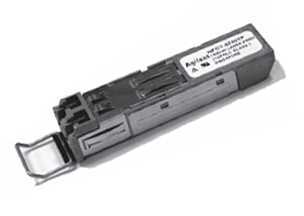
The firewall supports GE SFP transceiver modules For the transceiver module specifications, see "Appendix A Chassis views and technical specifications."
Only the F100-C-A1 and F100-C-A2 firewalls support transceiver modules.
No transceiver module is provided with the firewall. As a best practice, purchase transceiver modules from H3C as needed.
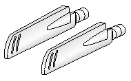
Figure2-15 GE SFP transceiver module
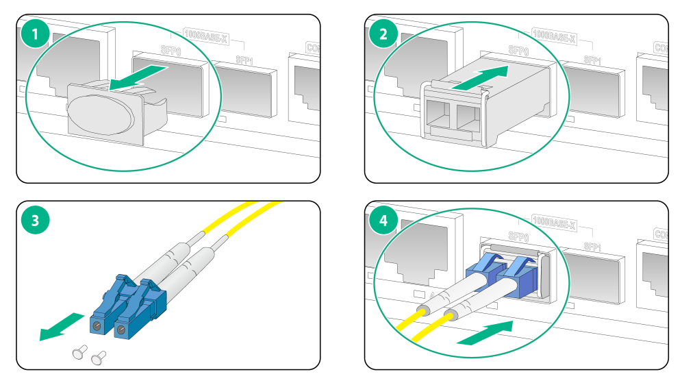
To connect the firewall to the network through an optical fiber:
1. Remove the dust plug from the fiber port.
2. Remove the dust cap from the transceiver module and insert it into the fiber port.
3. Remove the dust cap of the optical fiber connector, and use dust free paper and absolute alcohol clean the end face of the fiber connector.
4. Identify the Rx and Tx ports on the transceiver module. Plug one end of the optical fiber into the transceiver module in the firewall, and plug the other end into the transceiver module in the peer device.
Make sure the Rx port and the Tx port are connected to the Tx port and the Rx port on the peer device, respectively.
Figure2-16 Installing and connecting an optical fiber
Connecting the power adapter or power cord
|
|
CAUTION: Make sure the grounding cable of the firewall is correctly connected and the power source is powered off before connecting the power adapter or power cord. |
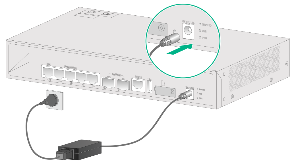
Connecting the power adapter for an F100-C-A1 or F100-C-A2 firewall
1. Make sure the firewall is reliably grounded.
2. Connect the power adapter to an external power source.
3. Connect the DC output plug of the power adapter to the power adapter receptacle on the firewall.
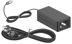
Figure2-17 Connecting the power adapter for an F100-C-A1 or F100-C-A2 firewall
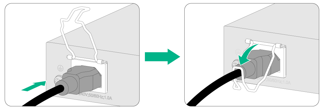
Connecting the AC power cord for an F100-C-A3, F100-C-A3-W, F100-C-A5, F100-C-A5-W, F100-C-A6, or F100-C-A6-WL firewall
1. Attach the hooks of the power cord retainer clip into the holes on the top of the AC-input power receptacle, and pull the power cord retainer clip upwards.
2. Connect one end of the AC power cord to the AC-input power receptacle on the firewall.
3. Pull the power cord retainer clip downwards and secure the connector to the power receptacle.
4. Connect the other end of the power cord to an AC power source.
Figure2-18 Connecting the AC power cord
Verifying the installation
Verify the following items to ensure correct installation:
· There is enough space for heat dissipation around the firewall.
· The firewall and its components are installed securely. The screws are fastened tightly.
· The power source specifications are as required by the firewall.
· The grounding cable and power cords are connected correctly.
3 Accessing the firewall
Starting the firewall
Pre-start checking
|
|
WARNING! Locate the emergency power-off switch in the room before powering on the firewall so you can quickly shut power off when an electrical accident occurs. |
Before powering on the firewall, verify that the following conditions are met:
· The power cord and grounding cable are correctly connected.
· The power source specifications meet the firewall requirements.
· The firewall is connected correctly to a configuration terminal (a PC for example). The configuration terminal has been started and the parameters have been set correctly. For more information, see "Logging in from the console port."
Starting the firewall and observing the initial startup conditions
1. Turn on the circuit breakers to power on the firewall.
2. Observe the initial startup conditions to verify that the firewall starts up correctly.
¡ The LEDs on the front panel indicate that the device is operating correctly. For more information about LEDs, see "Appendix B LEDs."
¡ The configuration terminal displays the following information:
System is starting...
Press Ctrl+D to access BASIC-BOOTWARE MENU
Booting Normal Extended BootWare
Press Ctrl+T to start heavy memory test
****************************************************************************
* *
* BootWare, Version 0.21 *
* *
****************************************************************************
Compiled Date : Jan 13 2022
Memory Type : DDR4 SDRAM
Memory Size : 2048MB
Flash Size : 512MB
PCB Version : 1.0
BootWare Validating...
Press Ctrl+B to access EXTENDED-BOOTWARE MENU...
Loading the main image files...
Loading file flash:/f100Cfw-cmw710-system-A8482.bin.........................
............................................................................
............................Done.
Loading file flash:/f100Cfw-cmw710-boot-A8482.bin...........Done.
Image file flash:/f100Cfw-cmw710-boot-A8482.bin is self-decompressing.......
............................................................................
............................................................................
...Done.
System image is starting...
Cryptographic algorithms tests passed.
Line con0 is available.
Press ENTER to get started.
Press Enter to access user view of the firewall.
|
|
NOTE: To access the EXTENDED-BOOTWARE menu, press Ctrl+B within four seconds at the prompt "Press Ctrl+B to access EXTENDED-BOOTWARE MENU." If you do not press Ctrl+B at the prompt, the system starts to read and decompress program files. To enter the EXTENDED-BOOT menu afterwards, you need to reboot the device. |
Logging in to the firewall
You can use the following methods to access and manage the firewall. For more information about logging in to the firewall, see login management in fundamentals configuration guide for the firewall.
· Logging in from the Web interface
· Logging in from the console port
Logging in from the Web interface
At the first login from the Web interface, you can use the default account or use an account created from the CLI. Table3-1 shows the default Web interface login information.
Table3-1 Default Web interface login information
|
Item |
Default configurations |
|
Username |
admin |
|
Password |
admin |
|
IP address of the management Ethernet port |
192.168.0.1/24 |
To log in to the firewall from the Web interface by using the default account:
1. Use an Ethernet cable to connect a PC to the Ethernet management port GigabitEthernet 1/0/0 on the firewall.
2. Configure an IP address in subnet 192.168.0.0/24 for the PC. Make sure the PC and the firewall are reachable to each other.
The PC must use a different IP address than the Ethernet management interface.
3. Start a browser, enter 192.168.0.1 in the address bar, and press Enter.
4. Enter the default username admin and password admin and then click Login.
Logging in from the console port
You can connect the console port on the firewall to a configuration terminal (a PC for example) for accessing the firewall for the first time.
By default, the firewall uses the scheme access authentication mode. The username and password are both admin.
You must run a terminal emulator program, TeraTermPro or PuTTY, on your configuration terminal and configure the following settings for the terminal. For more information about the terminal emulator programs, see the user guides for these programs.
· Bits per second—9600.
· Data bits—8.
· Stop bits—1.
· Parity—None.
· Flow control—None.
Logging in through Telnet
1. Log in to the firewall through the console port, and enable the Telnet function in system view by using the telnet server enable command.
2. Enter VTY user line view, and configure the authentication mode, user role, and common properties in VTY user line view.
By default, the authentication mode is scheme, and the username and password are admin.
3. Connect a PC to the Ethernet management port GigabitEthernet 1/0/0 on the firewall.
4. Specify an IP address for the network port of the PC. The IP address must be in subnet 192.168.0.0/24 and cannot be 192.168.0.1.
5. Run the Telnet client on the PC and enter the default login information.
4 Replacing a transceiver module
|
|
WARNING! Disconnected optical fibers or transceiver modules might emit invisible laser light. Do not stare into beams or view directly with optical instruments when the firewall is operating. |
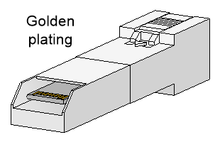
When you replace a transceiver module, make sure the two transceiver modules connected by the same optical fiber are the same type. Do not touch the golden plating of the transceiver module.
Figure4-1 Transceiver module golden plating
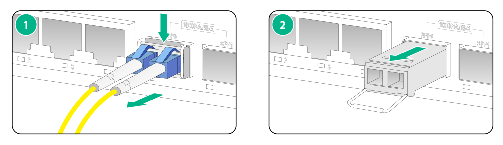
To replace a transceiver module:
1. Use the shutdown command in interface view at the CLI to shut down the optical source before you remove the fiber connector.
2. Remove the LC connectors with the optical fiber from the transceiver module, and install dust caps to the LC connectors.
3. Pivot the clasp of the transceiver module down to the horizontal position, and gently pull the transceiver module out.
Figure4-2 Removing the transceiver module
4. Install dust caps to the removed transceiver module, and put it into the package.
Install a new transceiver module. If you do not install a new transceiver module in the slot, install a dust cap. For information about installing a transceiver module, see "Connecting a fiber port."
5 Hardware management and maintenance
|
|
NOTE: Command outputs vary by firewall model and software version. For more information about the commands used in this chapter, see the configuration guides and command references for the firewall. |
Displaying detailed information about the firewall
Use the display device verbose command to display detailed information about the firewall, including the running status and hardware version.
<Sysname> display device verbose
Slot 1 SubSlot 0 info:
Status : Normal
Type : F100-C-A1
PCB 1 Ver : VER.A
Software Ver : 8482
CPU Ver : 1.0
CPLD_A : 0.0
CPLD_B : 0.0
CFCard Num : 0
Displaying software and hardware version information for the firewall
Use the display version command to display the software and hardware version information of the firewall.
H3C Comware Software, Version 7.1.064, Alpha 8482
Copyright (c) 2004-2022 New H3C Technologies Co., Ltd. All rights reserved.
H3C SecPath F100-C-A1 uptime is 0 weeks, 0 days, 0 hours, 6 minutes
Last reboot reason: User reboot
Boot image: flash:/f100Cfw-cmw710-boot-A8482.bin
Boot image version: 7.1.064, Alpha 8482
Compiled Mar 15 2022 14:00:00
System image: flash:/f100Cfw-cmw710-system-A8482.bin
System image version: 7.1.064, Alpha 8482
Compiled Mar 15 2022 14:00:00
SLOT 1
CPU type: Single-core CPU
DDR4 SDRAM Memory : 2004 MB
Board PCB Version : Ver.A
Basic BootWare Version : 257.00
Extend BootWare Version : 0.21 (Hardware)Ver.A, (Driver)1.0
Displaying electrical label information for the firewall
Use the display device manuinfo command to display the electrical label information of the firewall.
<Sysname> display device manuinfo
Slot 1 CPU 0:
DEVICE_NAME : F100-C-A1
DEVICE_SERIAL_NUMBER : 219801A3EP921AQ0000B
MAC_ADDRESS : D461-FE39-D20D
MANUFACTURING_DATE : NONE
VENDOR_NAME : NONE
Power 0:
The operation is not supported on the specified powe
Table5-1 Output description
|
Field |
Description |
|
DEVICE_NAME |
Firewall name. |
|
DEVICE_SERIAL_NUMBER |
Firewall serial number. |
|
MAC_ADDRESS |
MAC address of the firewall. |
|
MANUFACTURING_DATE |
Manufacturing date of the firewall. |
|
VENDOR_NAME |
Vendor name. |
Displaying the CPU usage of the firewall
Use the display cpu-usage command to display the CPU usage of the firewall.
<Sysname> display cpu-usage
Slot 1 CPU 0 CPU usage:
10% in last 5 seconds
10% in last 1 minute
10% in last 5 minutes
Table5-2 Output description
|
Field |
Description |
|
Slot 1 CPU 0 CPU usage |
CPU 0 usage information. |
|
10% in last 5 seconds |
Average CPU usage in the last 5 seconds. (After the firewall boots, the firewall calculates and records the average CPU usage at the interval of 5 seconds.) |
|
10% in last 1 minute |
Average CPU usage in the last minute. (After the firewall boots, the firewall calculates and records the average CPU usage at the interval of 1 minute.) |
|
10% in last 5 minutes |
Average CPU usage in the last 5 minutes. (After the firewall boots, the firewall calculates and records the average CPU usage at the interval of 5 minutes.) |
Displaying the memory usage of the firewall
Use the display memory command to display the memory information of the firewall.
Memory statistics are measured in KB:
Slot 1:
Total Used Free Shared Buffers Cached FreeRatio
Mem: 2052412 767152 1285260 0 3048 249320 63.5%
-/+ Buffers/Cache: 514784 1537628
Swap: 0 0 0
Table5-3 Output description
|
Field |
Description |
|
Mem |
Memory usage information. |
|
Total |
Total size of the physical memory space that can be allocated. The memory space is virtually divided into two parts. Part 1 is used for kernel codes, kernel management, and ISSU functions. Part 2 can be allocated and used for such tasks as running service modules and storing files. The size of part 2 equals the total size minus the size of part 1. |
|
Used |
Used physical memory. |
|
Free |
Free physical memory. |
|
Shared |
Physical memory shared by processes. |
|
Buffers |
Physical memory used for buffers. |
|
Cached |
Physical memory used for caches. |
|
FreeRatio |
Free memory ratio. |
|
-/+ Buffers/Cache |
-/+ Buffers/Cache:used = Mem:Used – Mem:Buffers – Mem:Cached, which indicates the physical memory used by applications. -/+ Buffers/Cache:free = Mem:Free + Mem:Buffers + Mem:Cached, which indicates the physical memory available for applications. |
|
Swap |
Swap memory. |
Displaying the operational status of the power module
The firewall has a fixed power module. Use the display power command to display the operational status of the power module.
<Sysname> display power
Slot 1 Power 0 Status: Normal
Table5-4 Output description
|
Field |
Description |
|
Power |
Number of the power module. |
|
Status |
Power module state: · Normal—The power module is operating correctly. · Absent—The power module is not present. · Abnormal—The power module is faulty. |
Displaying the operational statistics about the firewall
When you perform routine maintenance or the system fails, you might need to view the operational information of each functional module for locating failures. Typically you need to run display commands one by one. To collect more information one time, you can execute the display diagnostic-information command in any view to display or save the operational statistics of multiple functional modules of the firewall.
· Save the operational statistics of each functional module of the firewall:
<Sysname> display diagnostic-information
Save or display diagnostic information (Y=save, N=display)? [Y/N]:y
Please input the file name(*.tar.gz)[flash:/diag_H3C_20220505-152156.tar.gz]:
Diagnostic information is outputting to flash:/diag_H3C_20220505-152156.tar.gz.
Please wait...
Save successfully.
To view the diag.gz file:
a. Execute the gunzip diag.gz command in user view to decompress the file.
b. Execute the more diag command.
c. Press Pg Up and Pg Down.
· Display the operational statistics for each functional module of the firewall:
<Sysname> display diagnostic-information
<Sysname>display diagnostic-information
Save or display diagnostic information (Y=save, N=display)? [Y/N]:n
===============================================
===============display cpu===============
Slot 1 CPU 0 CPU usage:
10% in last 5 seconds
10% in last 1 minute
10% in last 5 minutes
...
Rebooting the firewall
|
|
CAUTION: · If the main system software image file does not exist, do not use the reboot command to reboot the firewall. Specify the main system software image file first, and then reboot the firewall. · The precision of the rebooting timer is 1 minute. 1 minute before the rebooting time, the firewall prompts "REBOOT IN ONE MINUTE" and reboots in one minute. · If you are performing file operations when the firewall is to be rebooted, the system does not execute the reboot command for security. |
To reboot a firewall, use one of the following methods:
· Use the reboot command to reboot the firewall immediately.
· Enable the scheduled reboot function at the CLI. You can set a time at which the firewall can automatically reboot, or set a delay so that the firewall can automatically reboot within the delay.
· Power on the firewall after powering it off, which is also called hard reboot or cold start. H3C does not recommend that you use this method because it might cause data loss and hardware damages.
To reboot the firewall immediately:
|
Task |
Command |
Remarks |
|
Reboot the firewall immediately. |
reboot |
Available in user view. |
To enable the scheduled reboot function:
|
Task |
Command |
Remarks |
|
Enable the scheduled reboot function. |
· Enable the scheduled reboot function and specify
a specific reboot time and date: · Enable the scheduled reboot function and
specify a reboot waiting time: |
Use either approach. The scheduled reboot function is disabled by default. Available in user view. |
6 Troubleshooting
Power failure
Symptom
The firewall cannot be powered on, and the power status LED (PWR) on the front panel is off.
Solution
To resolve the issue:
1. Turn off the circuit breaker for power input to the firewall.
2. Verify that the power source is as required by the firewall.
3. Verify that the power cord is firmly connected.
4. Verify that the power cord is in good condition.
5. If the issue persists, contact your local sales agent.
Configuration terminal display issue
Symptom
The configuration terminal displays nothing or garbled text when the firewall is powered on.
Solution
To resolve the issue:
1. Verify that the power system is operating correctly.
2. Verify that the console cable is correctly connected.
3. Verify that the console cable is connected to the serial port configured on the configuration terminal.
4. Verify that the configuration terminal parameters are configured as follows:
¡ Baud rate—9600.
¡ Data bits—8.
¡ Parity—None.
¡ Stop bits—1.
¡ Flow control—None.
¡ Terminal emulation—VT100.
5. Verify that the console cable is in good condition.
6. If the issue persists, contact your local sales agent.
Password loss
To deal with loss of the password used for accessing the firewall through the console port, see the release notes for the firewall.
Software loading failure
Symptom
The device fails in software loading.
Solution
To resolve the issue:
1. Verify that the physical ports are correctly connected.
2. Examine the software loading process displayed on the TeraTermPro or PuTTY for errors. Possible errors include:
¡ Inconsistent baud rates configured for XMODEM and the TeraTermPro or PuTTY.
¡ Incorrect IP address, software name, or TFTP serve path for TFTP.
¡ Incorrect IP address, software name, username, or password for FTP.
3. If the issue persists, contact your local sales agent.
7 Appendix A Chassis views and technical specifications
Chassis views
F100-C-A1
The F100-C-A1 firewall provides the following ports on the front panel:
· Two 1000BASE-X Ethernet fiber ports.
· Five 10/100/1000BASE-T autosensing Ethernet copper ports (including one management Ethernet port).
· One USB port.
· One console port.
· One Micro SD card slot.
Figure7-1 Front panel
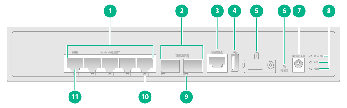
|
(1) 10/100/1000BASE-T copper ports |
(2) 1000BASE-X fiber ports |
|
(3) Console port |
(4) USB port (host mode, Type A) |
|
(5) Micro SD card slot |
(6) Reset button |
|
(7) DC-input power receptacle |
(8) Micro SD card, system status (SYS), and power status (PWR) LEDs |
|
(9) 1000BASE-X fiber port LED |
(10) 10/100/1000BASE-T Ethernet copper port LED |
|
(11) Management Ethernet port (MGMT) |
|
|
|
NOTE: The reset button restarts the firewall. It does not restore the factory defaults. |
Figure7-2 Rear panel
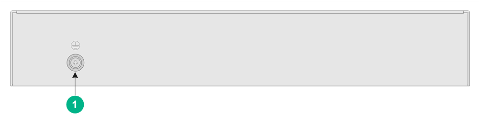
|
(1) Grounding screw |
F100-C-A2
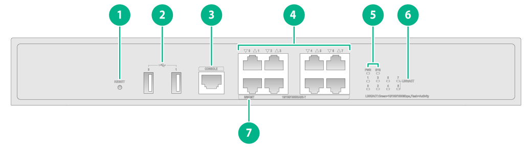
The F100-C-A2 firewall provides the following ports on the front panel:
· Two 1000BASE-X Ethernet fiber ports.
· Ten 10/100/1000BASE-T autosensing Ethernet copper ports (including one management Ethernet port).
· One USB port.
· One console port.
· One Micro SD card slot.
Figure7-3 Front panel
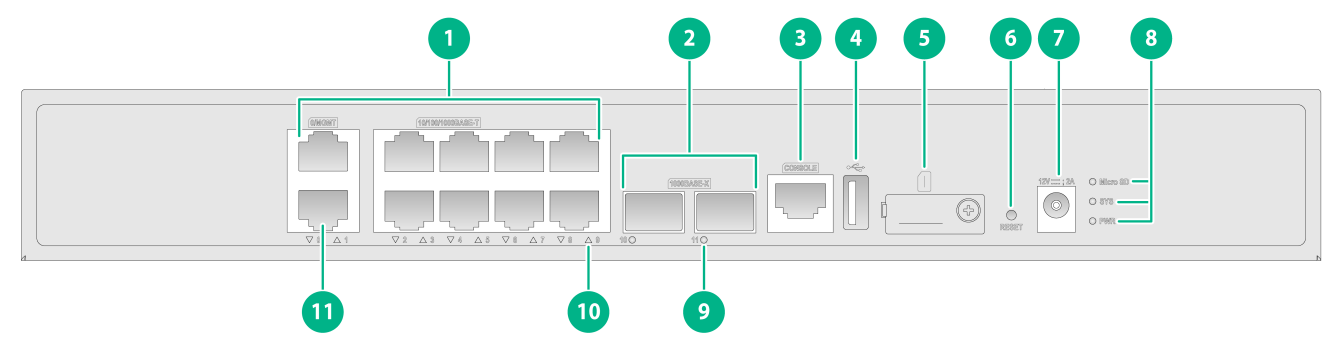
|
(1) 10/100/1000BASE-T copper ports |
(2) 1000BASE-X fiber ports |
|
(3) Console port |
(4) USB port (host mode, Type A) |
|
(5) Micro SD card slot |
(6) Reset button |
|
(7) DC-input power receptacle |
(8) Micro SD card, system status (SYS), and power status (PWR) LEDs |
|
(9) 1000BASE-X fiber port LED |
(10) 10/100/1000BASE-T copper port LED |
|
(11) Management Ethernet port (0/MGMT) |
|
|
|
NOTE: The reset button restarts the firewall. It does not restore the factory defaults. |
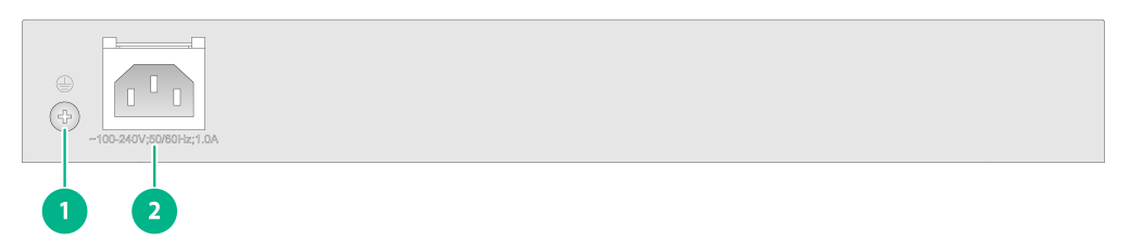
Figure7-4 Rear panel
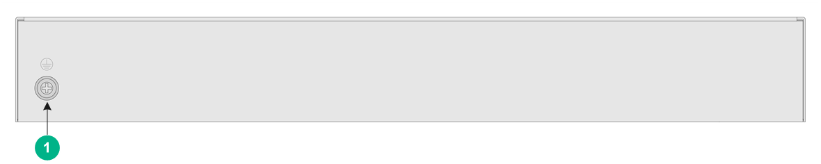
|
(1) Grounding screw |
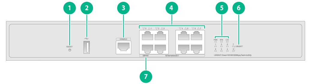
F100-C-A3/F100-C-A5
The F100-C-A3/F100-C-A5 firewall provides the following ports on the front panel:
· Eight 10/100/1000BASE-T autosensing Ethernet copper ports (including one management Ethernet port).
· Two USB ports.
· One console port.
Figure7-5 Front panel
|
(1) Reset button |
(2) USB ports |
|
(3) Console port |
(4) 10/100/1000BASE-T copper ports |
|
(5) System status (SYS) and power status (PWR) LEDs |
(6) 10/100/1000BASE-T copper port LED |
|
(7) Management Ethernet port (0/MGMT) |
|
|
|
NOTE: The reset button restarts the device. It does not restore the factory defaults. |
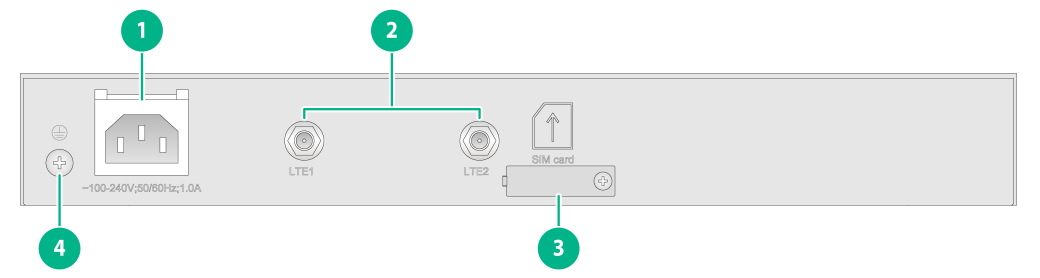
|
(1) Grounding screw |
(2) AC-input power receptacle |
F100-C-A3-W/F100-C-A5-W
The F100-C-A3-W/F100-C-A5-W firewall provides the following ports on the front panel:
· Eight 10/100/1000BASE-T autosensing Ethernet copper ports (including one management Ethernet port).
· One USB port.
· One console port.
Figure7-7 Front panel
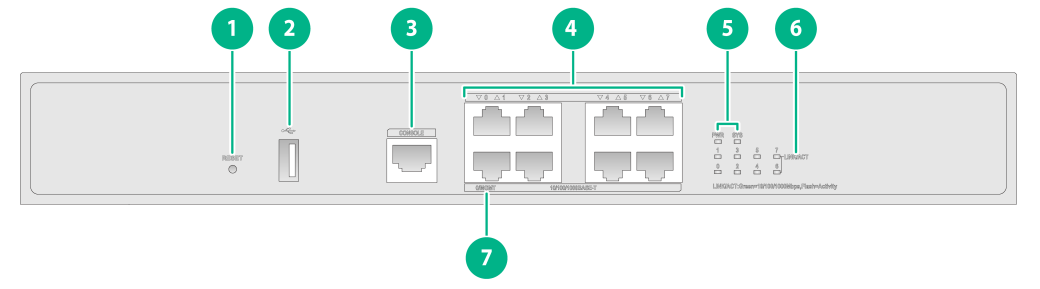
|
(1) Reset button |
(2) USB port |
|
(3) Console port |
(4) 10/100/1000BASE-T copper ports |
|
(5) System status (SYS) and power status (PWR) LEDs |
(6) 10/100/1000BASE-T copper port LED |
|
(7) Management Ethernet port (0/MGMT) |
|
|
|
NOTE: The reset button restarts the firewall. It does not restore the factory defaults. |
The F100-C-A3-W/F100-C-A5-W firewall provides one AC-input power receptacle and one WLAN module on the rear panel.
Figure7-8 Rear panel
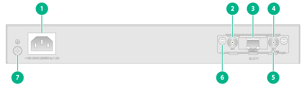
|
(1) AC-input power receptacle |
(2) Wi-Fi antenna connector 0 |
|
(3) WLAN module console port (used by technical support for debugging only) |
(4) Wi-Fi antenna connector 1 |
|
(5) WLAN module status LED |
(6) WLAN module |
|
(7) Grounding screw |
|
F100-C-A6
The F100-C-A6 firewall provides the following ports on the front panel:
· Eight 10/100/1000BASE-T autosensing Ethernet copper ports (including one management Ethernet port).
· One USB port.
· One console port.
Figure7-9 Front panel
|
(1) Reset button |
(2) USB port |
|
(3) Console port |
(4) 10/100/1000BASE-T copper ports |
|
(5) LTE card status, system status (SYS), and power status (PWR) LEDs |
(6) 10/100/1000BASE-T copper port LED |
|
(7) Management Ethernet port (0/MGMT) |
|
|
|
NOTE: The reset button restarts the firewall. It does not restore the factory defaults. |
Figure7-10 Rear panel
|
(1) AC-input power receptacle |
(2) 4G antenna connectors |
|
(3) SIM card slot |
(4) Grounding screw |
F100-C-A6-WL
The F100-C-A6-WL firewall provides the following ports on the front panel:
· Eight 10/100/1000BASE-T autosensing Ethernet copper ports (including one management Ethernet port).
· One USB port.
· One console port.
Figure7-11 Front panel
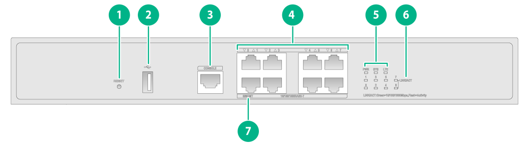
|
(1) Reset button |
(2) USB port |
|
(3) Console port |
(4) 10/100/1000BASE-T copper ports |
|
(5) LTE card status, system status (SYS), and power status (PWR) LEDs |
(6) 10/100/1000BASE-T copper port LED |
|
(7) Management Ethernet port (0/MGMT) |
|
|
|
NOTE: The reset button restarts the firewall. It does not restore the factory defaults. |
The F100-C-A6-WL firewall provides one AC-input power receptacle, two 4G antenna ports, one SIM card slot, and one WLAN module.
Figure7-12 Rear panel
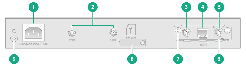
|
(1) AC-input power receptacle |
(2) 4G antenna connector |
|
(3) Wi-Fi antenna connector 0 |
(4) WLAN module console port (used by technical support for debugging only) |
|
(5) Wi-Fi antenna connector 1 |
(6) WLAN module status LED |
|
(7) WLAN module |
(8) SIM card slot |
|
(9) Grounding screw |
|
Technical specifications
Dimensions and weights
Table7-1 Dimensions and weights
|
Dimensions (H × W × D), excluding rubber feet and mounting brackets |
Weight (fully configured) |
|
|
F100-C-A1 |
44 × 266 × 161 mm (1.73 × 10.47 × 6.34 in) |
1 kg (2.20 lb) |
|
F100-C-A2 |
44 × 330 × 230 mm (1.73 × 12.99 × 9.06 in) |
1.6 kg (3.53 lb) |
|
F100-C-A3 |
43.6 × 330 × 230 mm (1.72 × 12.99 × 9.06 in) |
1.8 kg (3.97 lb) |
|
F100-C-A5 |
43.6 × 330 × 230 mm (1.72 × 12.99 × 9.06 in) |
1.8 kg (3.97 lb) |
|
F100-C-A6 |
43.6 × 330 × 230 mm (1.72 × 12.99 × 9.06 in) |
2 kg (4.41 lb) |
|
F100-C-A3-W/F100-C-A5-W/F100-C-A6-WL |
43.6 × 330 × 230 mm (1.72 × 12.99 × 9.06 in) |
2.2 kg (4.85 lb) |
Storage media
Table7-2 Storage media specifications
|
Firewall model |
Memory |
|
F100-C-A1/F100-C-A2 |
2GB DDR4 |
|
F100-C-A3/F100-C-A5/F100-C-A6/F100-C-A3-W/F100-C-A5-W/F100-C-A6-WL |
2GB DDR3 |
Power consumption
Table7-3 Power consumption
|
Firewall model |
System power consumption |
|
F100-C-A1 |
10.5 W |
|
F100-C-A2 |
12 W |
|
F100-C-A3 |
20 W |
|
F100-C-A5 |
20 W |
|
F100-C-A3-W/F100-C-A5-W/F100-C-A6 |
25 W |
|
F100-C-A6-WL |
30 W |
Power specifications
Table7-4 Power specifications for the F100-C-A1/F100-C-A2 firewall
|
Item |
Specification |
|
Rated input voltage |
12 VDC @ 50 Hz or 60 Hz |
|
Maximum input current |
· F100-C-A1: 1.5 A · F100-C-A2: 2 A |
|
Maximum power |
24 W |
Table7-5 Power specifications for the F100-C-A3/F100-C-A3-W/F100-C-A5/F100-C-A5-W/F100-C-A6/F100-C-A6-WL firewall
|
Item |
Specification |
|
Rated input voltage range |
100 VAC to 240 VAC @ 50 Hz or 60 Hz |
|
Maximum input current |
1 A |
|
Maximum power |
36 W |
Port specifications
Console port
Table7-6 Console port specifications
|
Item |
Specification |
|
Connector |
RJ-45 |
|
Standard compliance |
RS-232 |
|
Baud rate |
9600 bps (default) to 115200 bps |
|
Cable type |
Common asynchronous serial port cable |
|
Transmission distance |
≤ 15 m (49.21 ft) |
|
Services |
· Connection to an ASCII terminal · Connection to the serial port of a local PC running the terminal emulation program · CLI |
GE copper port
Table7-7 GE copper port specifications
|
Item |
Specification |
|
Connector |
RJ-45 |
|
Standard compliance |
802.3, 802.3u, and 802.3ab |
|
Auto-MDI/MDIX |
Supported |
|
Cable type |
Category 5 or above twisted pair cable |
|
Transmission distance |
100 m (328.08 ft) |
|
Data rate and duplex mode |
10/100/100 Mbps autosensing: · 10 Mbps, half/full-duplex auto-negotiation · 100 Mbps, half/full-duplex auto-negotiation · 1000 Mbps, full-duplex auto-negotiation |
|
|
NOTE: The Ethernet ports on NICs are typically media dependent interface (MDI) ports. The ports on hubs and LAN switches are typically media dependent interface crossover (MDIX) ports. |
GE fiber port
Table7-8 GE fiber port specifications
|
Item |
Specification |
|
Connector |
LC |
|
Transceiver module type |
SFP |
|
Standard compliance |
1000BASE-X |
|
Transmission rate |
1000 Mbps |
|
Duplex mode |
Full duplex |
Table7-9 SFP copper transceiver module specifications
|
Transceiver module |
Transmission distance |
Transmission rate |
Connector type |
|
SFP-GE-T |
100 m (328.08 ft) |
1250 Mbps |
RJ-45 |
Table7-10 1000BASE-X SFP fiber transceiver module specifications (1)
|
Transceiver module |
Central wavelength (nm) |
Fiber mode |
Fiber diameter (µm) |
Mode bandwidth (MHz*km) |
|
SFP-GE-SX-MM850-A |
850 |
MMF |
50/125 |
500 |
|
400 |
||||
|
62.5/125 |
200 |
|||
|
160 |
||||
|
SFP-GE-LX-SM1310-A |
1310 |
SMF |
9/125 |
N/A |
|
MMF |
50/125 |
500/400 |
||
|
62.5/125 |
500 |
|||
|
SFP-GE-LH40-SM1310 |
1310 |
SMF |
9/125 |
N/A |
|
SFP-GE-LH40-SM1550 |
1550 |
SMF |
9/125 |
N/A |
|
SFP-GE-LH80-SM1550 |
1550 |
SMF |
9/125 |
N/A |
|
SFP-GE-LH100-SM1550 |
1550 |
SMF |
9/125 |
N/A |
Table7-11 1000BASE-X SFP fiber transceiver module specifications (2)
|
Transceiver module |
Transmission distance |
Transmitted optical power (dBm) |
Received optical power (dBm) |
|
SFP-GE-SX-MM850-A |
550 m (1804.46 ft) |
–9.5 to 0 |
–17 to –3 |
|
500 m (1640.42 ft) |
|||
|
275 m (902.23 ft) |
|||
|
220 m (721.78 ft) |
|||
|
SFP-GE-LX-SM1310-A |
10 km (6.21 miles) |
–9.5 to –3 |
–20 to –3 |
|
550 m (1804.46 ft) |
|||
|
550 m (1804.46 ft) |
|||
|
SFP-GE-LH40-SM1310 |
40 km (24.86 miles) |
–5 to +5 |
–22 to –3 |
|
SFP-GE-LH40-SM1550 |
40 km (24.86 miles) |
–4 to +1 |
–21 to –3 |
|
SFP-GE-LH80-SM1550 |
80 km (49.71 miles) |
–4 to +5 |
–22 to –3 |
|
SFP-GE-LH100-SM1550 |
100 km (62.14 miles) |
0 to 5 |
–30 to –9 |
|
|
NOTE: Only the F100-C-A1 and F100-C-A2 firewalls support GE transceiver modules. |
WLAN module ports
The WLAN module (model: SIC-AP320) is a WLAN access module that sends and receives wireless packets. It has two Wi-Fi antenna connectors and is compliant with 802.11a/b/g/n/ac. It supports 2.4 GHz and 5 GHz bands.
Table7-12 WLAN module ports
|
Item |
Specification |
|
Connector |
RJ-45 |
|
Port |
One console port |
|
Port standard |
Console port: RS/EIA-232 |
|
RF interface |
· Radio 1: 5 GHz, MIMO 1 × 1 · Radio 2: 2.4 GHz, MIMO 2 × 2 |
|
Cable |
Console port: Common asynchronous serial port cable |
|
|
NOTE: Only the F100-C-A3-W, F100-C-A5-W, and F100-C-A6-WL firewalls support WLAN modules. |
8 Appendix B LEDs
F100-C-A1
Figure8-1 LEDs

Table8-1 LED description for the F100-C-A1 firewall
|
LED |
Mark |
Status |
Description |
|
10/100/1000BASE-T copper port LED |
10/100/1000BASE-T |
Off |
No link is present. |
|
Steady green |
A link is present. |
||
|
Flashing green |
The port is receiving and sending data. |
||
|
1000BASE-X fiber port LED |
1000BASE-X |
Off |
No link is present. |
|
Steady green |
A 1000 Mbps link is present. |
||
|
Flashing green |
The port is receiving and sending data at 1000 Mbps. |
||
|
Micro SD card LED |
Micro SD |
On |
A Micro SD card is present. |
|
Off |
No Micro SD card is detected. |
||
|
Power status LED |
PWR |
Off |
The power system is faulty. |
|
Steady green |
The power system is operating correctly. |
||
|
System status LED |
SYS |
Off |
The firewall is not powered on or has failed. |
|
Slow flashing green |
The firewall is operating correctly. |
||
|
Fast flashing green |
The firewall is loading software. |
F100-C-A2
Figure8-2 LEDs
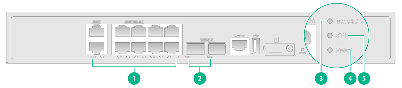
Table8-2 LED description for the F100-C-A2 firewall
|
LED |
Mark |
Status |
Description |
|
10/100/1000BASE-T copper port LED |
10/100/1000BASE-T |
Off |
No link is present. |
|
Steady green |
A link is present. |
||
|
Flashing green |
The port is receiving and sending data. |
||
|
1000BASE-X fiber port LED |
1000BASE-X |
Off |
No link is present. |
|
Steady green |
A 1000 Mbps link is present. |
||
|
Flashing green |
The port is receiving and sending data at 1000 Mbps. |
||
|
Micro SD card LED |
Micro SD |
On |
A Micro SD card is present. |
|
Off |
No Micro SD card is detected. |
||
|
Power status LED |
PWR |
Off |
The power system is faulty. |
|
Steady green |
The power system is operating correctly. |
||
|
System status LED |
SYS |
Off |
The firewall is not powered on or has failed. |
|
Slow flashing green |
The firewall is operating correctly. |
||
|
Fast flashing green |
The firewall is loading software. |
F100-C-A3/F100-C-A5/F100-C-A6
The F100-C-A3, F100-C-A5, and F100-C-A6 firewalls use similar LEDs. This section uses the LEDs on the F100-C-A6 firewall as an example.
Figure8-3 LEDs
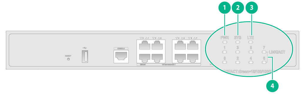
Table8-3 LED description for the F100-C-A3/F100-C-A5/F100-C-A6 firewall
|
LED |
Mark |
Status |
Description |
|
Power status LED |
PWR |
Off |
The power system is faulty. |
|
Steady green |
The power system is operating correctly. |
||
|
System status LED |
SYS |
Off |
The firewall is not powered on or has failed. |
|
Slow flashing green |
The firewall is operating correctly. |
||
|
Fast flashing green |
The firewall is loading software. |
||
|
4G module LED (available only on the F100-C-A6 firewall) |
LTE |
Off |
The 4G module is faulty or in airplane mode. |
|
Flashing green (1 Hz) |
The 4G module is searching for a network. |
||
|
Flashing green (0.3 Hz) |
The 4G module has connected to a network. |
||
|
Flashing green (2.5 Hz) |
The 4G module is transmitting data. |
||
|
10/100/1000BASE-T copper port LED |
10/100/1000BASE-T |
Off |
No link is present. |
|
Steady green |
A link is present. |
||
|
Flashing green |
The port is receiving and sending data. |
F100-C-A3-W/F100-C-A5-W/F100-C-A6-WL
The F100-C-A3-W, F100-C-A5-W, and F100-C-A6-WL firewalls use similar LEDs. This section uses the LEDs on the F100-C-A6-WL firewall as an example.
Figure8-4 LEDs
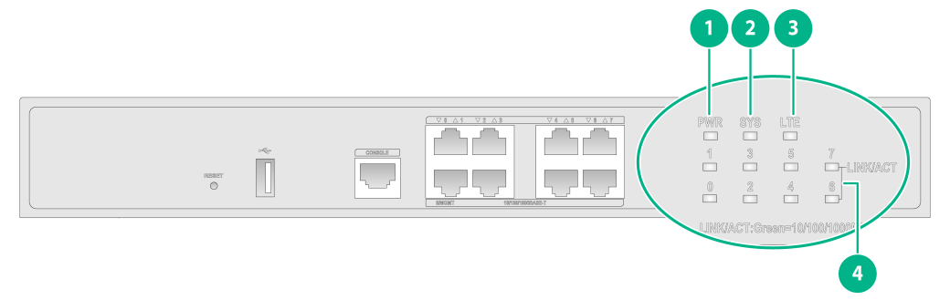
Table8-4 LED description for the F100-C-A3-W/F100-C-A5-W/F100-C-A6-WL firewall
|
LED |
Mark |
Status |
Description |
|
Power status LED |
PWR |
Off |
The power system is faulty. |
|
Steady green |
The power system is operating correctly. |
||
|
System status LED |
SYS |
Off |
The firewall is not powered on or has failed. |
|
Slow flashing green |
The firewall is operating correctly. |
||
|
Fast flashing green |
The firewall is loading software. |
||
|
4G module LED(available only on the F100-C-A6-WL firewall) |
LTE |
Off |
The 4G module is faulty or in airplane mode. |
|
Flashing green (1 Hz) |
The 4G module is searching for a network. |
||
|
Flashing green (0.3 Hz) |
The 4G module has connected to a network. |
||
|
Flashing green (2.5 Hz) |
The 4G module is transmitting data. |
||
|
10/100/1000BASE-T copper port LED |
10/100/1000BASE-T |
Off |
No link is present. |
|
Steady green |
A link is present. |
||
|
Flashing green |
The port is receiving and sending data. |
WLAN (SIC-AP320)
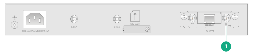
Table8-5 LED description for the WLAN module (SIC-AP320)
|
LED |
Mark |
Status |
Description |
|
WLAN module status LED |
SYS |
Steady amber |
The firewall is starting up. |
|
Flashing green |
The 2.4 GHz radio has client access. |
||
|
Flashing amber |
The 5 GHz radio has client access. |
||
|
Alternating between yellow and amber |
Both the 2.4 GHz and 5 GHz radios have client access. |
9 Appendix C Cables
Console cable
A console cable is an 8-core shielded cable with an RJ-45 connector at one end and a DB9 female connector at the other end. It is used to connect the console port on the firewall to a serial port on a configuration terminal (for example, a PC):
· Connect the DB9 female connector of the cable to the 8-core serial port on the configuration terminal.
· Connect the RJ-45 connector of the cable to the console port on the firewall.
Figure9-1 Console cable
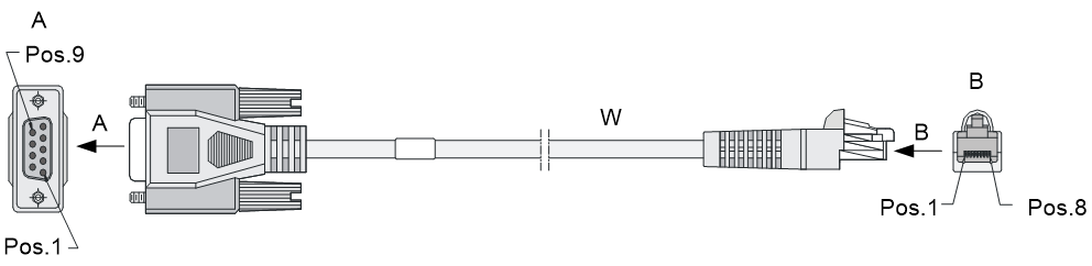
Table9-1 Console cable pinouts
|
RJ-45 |
Signal |
Direction |
DB-9 |
|
1 |
RTS |
← |
7 |
|
2 |
DTR |
← |
4 |
|
3 |
TXD |
← |
3 |
|
4 |
CD |
→ |
1 |
|
5 |
GND |
- |
5 |
|
6 |
RXD |
→ |
2 |
|
7 |
DSR |
→ |
6 |
|
8 |
CTS |
→ |
8 |
Ethernet twisted pair cable
Introduction
An Ethernet twisted pair cable consists of four pairs of insulated copper wires twisted together. Every wire uses a different color, and has a diameter of about 1 mm (0.04 in). A pair of twisted copper cables can cancel the electromagnetic radiation of each other, and reduce interference of external sources. An Ethernet twisted pair cable mainly transmits analog signals and is advantageous in transmitting data over shorter distances. It is the commonly used transmission media of the Ethernet. The maximum transmission distance of the Ethernet twisted pair cable is 100 m (328.08 ft). To extend the transmission distance, you can connect two twisted pair cable segments with a repeater. At most four repeaters can be added, which means five segments can be joined together to provide a transmission distance of 500 m (1640.42 ft).
Ethernet twisted pair cables can be classified into category 3, category 4, category 5, category 5e, category 6, and category 7 cables based on performance. In LANs, category 5, category 5e, and category 6 are commonly used.
Table9-2 Description for commonly used Ethernet twisted pair cables
|
Type |
Description |
|
Category 5 |
Suitable for data transmission at a maximum speed of 100 Mbps |
|
Category 5e |
Suitable for data transmission at a maximum speed of 1000 Mbps |
|
Category 6 |
Suitable for data transmission at a speed higher than 1 Gbps |
Based on whether a metal shielding is used, Ethernet twisted pair cables can be classified into shielded twisted pair (STP) and unshielded twisted pair (UTP). An STP cable provides a metallic braid between the twisted pairs and the outer jacket. This metallic braid helps reduce radiation, prevent information from being listened, and eliminate external electromagnetic interference (EMI) of external sources. STPs have strict application requirements and are expensive although they provide better EMI prevention performance than UTPs, so in most LANs, UTPs are commonly used.
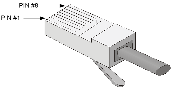
An Ethernet twisted pair cable connects network devices through the RJ-45 connectors at the two ends. Figure9-2 shows the pinouts of an RJ-45 connector.
Figure9-2 RJ-45 connector pinout
|
|
NOTE: The RJ-45 Ethernet ports of the firewall use category 5 or higher Ethernet twisted pair cables for connection. |
EIA/TIA cabling specifications define two standards, 568A and 568B, for cable pinouts.
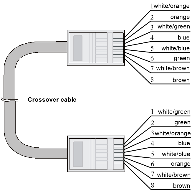
· Standard 568A—pin 1: white/green stripe, pin 2: green solid, pin 3: white/orange stripe, pin 4: blue solid, pin 5: white/blue stripe, pin 6: orange solid, pin 7: white/brown stripe, pin 8: brown solid.
· Standard 568B—pin 1: white/orange stripe, pin 2: orange solid, pin 3: white/green stripe, pin 4: blue solid, pin 5: white/blue stripe, pin 6: green solid, pin 7: white/brown stripe, pin 8: brown solid.
Ethernet twisted pair cables can be classified into straight-through and crossover cables based on their pinouts.
· Straight-through—The pinouts at both ends are T568B compliant, as shown in Figure9-3.
· Crossover—The pinouts are T568B compliant at one end and T568A compliant at the other end, as shown in Figure9-4.
Figure9-3 Straight-through cable

Select an Ethernet twisted pair cable according to the RJ-45 Ethernet port type on your device. An RJ-45 Ethernet port can be MDI (for routers and PCs) or MDIX (for switches). Table9-3 and Table9-4 show their pinouts.
Table9-3 RJ-45 MDI port pinouts
|
Pin |
10BASE-T/100BASE-TX |
1000BASE-T |
||
|
Signal |
Function |
Signal |
Function |
|
|
1 |
Tx+ |
Sends data |
BIDA+ |
Bi-directional data cable A+ |
|
2 |
Tx- |
Sends data |
BIDA- |
Bi-directional data cable A- |
|
3 |
Rx+ |
Receives data |
BIDB+ |
Bi-directional data cable B+ |
|
4 |
Reserved |
N/A |
BIDC+ |
Bi-directional data cable C+ |
|
5 |
Reserved |
N/A |
BIDC- |
Bi-directional data cable C- |
|
6 |
Rx- |
Receives data |
BIDB- |
Bi-directional data cable B- |
|
7 |
Reserved |
N/A |
BIDD+ |
Bi-directional data cable D+ |
|
8 |
Reserved |
N/A |
BIDD- |
Bi-directional data cable D- |
Table9-4 RJ-45 MDIX port pinouts
|
Pin |
10BASE-T/100BASE-TX |
1000BASE-T |
||
|
Signal |
Function |
Signal |
Function |
|
|
1 |
Rx+ |
Receives data |
BIDB+ |
Bi-directional data cable B+ |
|
2 |
Rx- |
Receives data |
BIDB- |
Bi-directional data cable B- |
|
3 |
Tx+ |
Sends data |
BIDA+ |
Bi-directional data cable A+ |
|
4 |
Reserved |
N/A |
BIDD+ |
Bi-directional data cable D+ |
|
5 |
Reserved |
N/A |
BIDD- |
Bi-directional data cable D- |
|
6 |
Tx- |
Sends data |
BIDA- |
Bi-directional data cable A- |
|
7 |
Reserved |
N/A |
BIDC+ |
Bi-directional data cable C+ |
|
8 |
Reserved |
N/A |
BIDC- |
Bi-directional data cable C- |
To ensure normal communication, the pins for sending data on one port must correspond to the pins for receiving data on the peer port. When both of the ports on the two devices are MDI or MDIX, use a crossover Ethernet cable; when one port is MDI and the other is MDIX, use a straight-through Ethernet cable. To summarize, straight-through and crossover cables connect the following devices:
· Straight-through cables connect devices of different types—for example, router to PC and router to switch.
· Crossover cables connect devices of the same type—for example, switch to switch, router to router, and PC to PC.
If an RJ-45 Ethernet port is enabled with MDI/MDIX autosensing, it can automatically negotiate pin roles.
|
|
NOTE: The RJ-45 Ethernet ports on the firewall support MDI/MDIX autosensing. |
Making an Ethernet twisted pair cable
1. Cut the cable to a required length with the crimping tool.
2. Strip off an appropriate length of the cable sheath. The length is typically that of the RJ-45 connector.
3. Untwist the pairs so that they can lay flat, and arrange the colored wires based on the wiring specifications.
4. Cut the top of the wires even with one another. Insert the wires into the RJ-45 connector and make sure the wires extend to the front of the RJ-45 connector and make good contact with the metal contacts in the RJ-45 connector and in the correct order.
5. Crimp the RJ-45 connector with the crimping tool until you hear a click.
6. Use a cable tester to verify the connectivity of the cable.