- Table of Contents
- Related Documents
-
| Title | Size | Download |
|---|---|---|
| 02-Ethernet interface configuration | 141.68 KB |
Contents
Configuring Ethernet interfaces
Configuring a management Ethernet interface
Configuring common Ethernet interface settings
Configuring the physical type for a combo interface (single combo interface)
Configuring basic settings of an Ethernet interface
Configuring basic settings of an Ethernet subinterface
Configuring the link mode of an Ethernet interface
Configuring jumbo frame support
Configuring dampening on an Ethernet interface
Configuring generic flow control on an Ethernet interface
Setting the statistics polling interval
Enabling loopback testing on an Ethernet interface
Restoring the default settings for an interface
Configuring a Layer 2 Ethernet interface
Configuring a Layer 3 Ethernet interface or subinterface
Hardware compatibility with Layer 3 Ethernet interfaces or subinterfaces
Setting the MTU for an Ethernet interface or subinterface
Setting the MAC address of an Ethernet interface or subinterface
Display and maintenance commands
Configuring Ethernet interfaces
About Ethernet interface
The device supports Ethernet interfaces, management Ethernet interfaces, Console interfaces, and USB interfaces. For the interface types and the number of interfaces supported by a device model, see the installation guide.
This chapter describes how to configure management Ethernet interfaces and Ethernet interfaces.
Configuring a management Ethernet interface
About this task
A management interface uses an RJ-45 connector. You can connect the interface to a PC for software loading and system debugging, or connect it to a remote NMS for remote system management.
Procedure
1. Enter system view.
system-view
2. Enter management Ethernet interface view.
interface M-GigabitEthernet interface-number
3. (Optional.) Set the interface description.
description text
The default setting is M-GigabitEthernet0/0/0 Interface.
4. (Optional.) Set the duplex mode for the management Ethernet interface.
duplex { auto | full | half }
By default, the duplex mode is auto for a management Ethernet interface.
Support for this feature varies by device model. For more information, see the command reference.
5. (Optional.)_Set the speed for the management Ethernet interface.
speed { 10 | 100 | 1000 | auto }
By default, the speed is auto for a management Ethernet interface.
6. (Optional.) Shut down the interface.
shutdown
By default, the management Ethernet interface is up.
|
|
CAUTION: Executing the shutdown command on an interface will disconnect the link of the interface and interrupt communication. Use this command with caution. |
Configuring common Ethernet interface settings
Configuring the physical type for a combo interface (single combo interface)
About this task
A combo interface is a logical interface that physically comprises one fiber combo port and one copper combo port. The two ports share one forwarding channel and one interface view. As a result, they cannot work simultaneously. When you activate one port, the other port is automatically disabled. In the interface view, you can activate the fiber or copper combo port, and configure other port attributes such as the interface rate and duplex mode.
Configuring basic settings of an Ethernet interface
About this task
You can configure an Ethernet interface to operate in one of the following duplex modes:
· Full-duplex mode—The interface can send and receive packets simultaneously.
· Half-duplex mode—The interface can only send or receive packets at a given time.
· Autonegotiation mode—The interface negotiates a duplex mode with its peer.
You can set the speed of an Ethernet interface or enable it to automatically negotiate a speed with its peer.
Restrictions and guidelines
The shutdown and loopback commands are mutually exclusive.
Procedure
1. Enter system view.
system-view
2. Enter Ethernet interface view.
interface interface-type interface-number
3. Set the description for the Ethernet interface.
description text
The default setting is interface-name Interface. For example, GigabitEthernet1/0/1 Interface.
4. Set the duplex mode for the Ethernet interface.
duplex { auto | full | half }
By default, the duplex mode is auto for an Ethernet interface.
Support for this feature varies by device model. For more information, see the command reference.
Fiber ports do not support the half keyword.
5. Set the speed for the Ethernet interface.
speed { 100 | 1000 | 2500 | 10000 | 40000 | auto }
By default, an interface autonegotiates its speed.
6. Set the expected bandwidth for the Ethernet interface.
bandwidth bandwidth-value
By default, the expected bandwidth (in kbps) is the interface baud rate divided by 1000.
7. Bring up the Ethernet interface.
undo shutdown
By default, an Ethernet interface is up.
Configuring basic settings of an Ethernet subinterface
Restrictions and guidelines for Ethernet subinterface basic settings
· To transmit and receive packets through an Ethernet subinterface, you must associate it with a VLAN. For more information, see VLAN termination configuration in Network Connectivity Configuration Guide.
· To transmit packets between a local Ethernet subinterface and a remote Ethernet subinterface, configure them with the same subinterface number and VLAN ID.
· Before creating a Layer 3 Ethernet subinterface, do not reserve a resource for the VLAN interface whose interface number is the subinterface number. After you reserve a VLAN interface resource, do not create a Layer 3 Ethernet subinterface whose subinterface number is the VLAN interface number. A Layer 3 Ethernet subinterface uses the VLAN interface resource in processing tagged packets whose VLAN ID matches the subinterface number. For more information about reserving resources for VLAN interfaces, see VLAN configuration in Network Connectivity Configuration Guide.
· The shutdown command cannot be configured on an Ethernet interface in a loopback test.
Procedure
1. Enter system view.
system-view
2. Create an Ethernet subinterface.
interface interface-type interface-number.subnumber
3. Set the description for the Ethernet subinterface.
description text
The default setting is interface-name Interface. For example, GigabitEthernet1/0/1.1 Interface.
4. Set the expected bandwidth for the Ethernet subinterface.
bandwidth bandwidth-value
By default, the expected bandwidth (in kbps) is the interface baud rate divided by 1000.
5. Bring up the Ethernet subinterface.
undo shutdown
By default, an Ethernet subinterface is up.
Configuring the link mode of an Ethernet interface
Hardware and feature compatibility
|
Hardware series |
Models |
Product code |
Feature compatibility |
|
WX1800H series |
WX1804H-PWR |
EWP-WX1804H-PWR-CN |
Yes |
|
WX2500H series |
WX2508H-PWR-LTE WX2510H-PWR WX2510H-F-PWR WX2540H WX2540H-F WX2560H |
EWP-WX2508H-PWR-LTE EWP-WX2510H-PWR EWP-WX2510H-F-PWR EWP-WX2540H EWP-WX2540H-F EWP-WX2560H |
Yes |
|
MAK series |
MAK204 MAK206 |
EWP-MAK204 EWP-MAK206 |
Yes |
|
WX3000H series |
WX3010H WX3010H-X-PWR WX3010H-L-PWR WX3024H WX3024H-L-PWR WX3024H-F |
EWP-WX3010H EWP-WX3010H-X-PWR EWP-WX3010H-L-PWR EWP-WX3024H EWP-WX3024H-L-PWR EWP-WX3024H-F |
No |
|
WX3500H series |
WX3508H WX3508H WX3510H WX3510H WX3520H WX3520H-F WX3540H WX3540H |
EWP-WX3508H EWP-WX3508H-F EWP-WX3510H EWP-WX3510H-F EWP-WX3520H EWP-WX3520H-F EWP-WX3540H EWP-WX3540H-F |
No |
|
WX5500E series |
WX5510E WX5540E |
EWP-WX5510E EWP-WX5540E |
No |
|
WX5500H series |
WX5540H WX5560H WX5580H |
EWP-WX5540H EWP-WX5560H EWP-WX5580H |
No |
|
Access controller modules |
LSUM1WCME0 EWPXM1WCME0 LSQM1WCMX20 LSUM1WCMX20RT LSQM1WCMX40 LSUM1WCMX40RT EWPXM2WCMD0F EWPXM1MAC0F |
LSUM1WCME0 EWPXM1WCME0 LSQM1WCMX20 LSUM1WCMX20RT LSQM1WCMX40 LSUM1WCMX40RT EWPXM2WCMD0F EWPXM1MAC0F |
No |
|
Hardware series |
Models |
Product code |
Feature compatibility |
|
WX1800H series |
WX1804H-PWR WX1810H-PWR WX1820H WX1840H |
EWP-WX1804H-PWR EWP-WX1810H-PWR EWP-WX1820H EWP-WX1840H-GL |
Yes |
|
WX3800H series |
WX3820H WX3840H |
EWP-WX3820H-GL EWP-WX3840H-GL |
No |
|
WX5800H series |
WX5860H |
EWP-WX5860H-GL |
No |
About this task
Ethernet interfaces operate differently depending on the hardware structure of interface cards:
· Some Ethernet interfaces can operate only as Layer 2 Ethernet interfaces (in bridge mode).
· Some Ethernet interfaces can operate only as Layer 3 Ethernet interfaces (in route mode).
· Some Ethernet interfaces can operate either as Layer 2 or Layer 3 Ethernet interfaces. You can set the link mode to bridge or route for these Ethernet interfaces.
Procedure
1. Enter system view.
system-view
2. Enter Ethernet interface view.
interface interface-type interface-number
3. Configure the link mode of the Ethernet interface.
port link-mode { bridge | route }
The default setting varies by interface card model.
|
|
CAUTION: Changing the link mode of an Ethernet interface also restores all commands (except shutdown and combo enable) on the Ethernet interface to their defaults in the new link mode. |
Configuring jumbo frame support
About this task
Jumbo frames are frames larger than a device-specific size and are typically received by an Ethernet interface during high-throughput data exchanges, such as file transfers. For more information, see Interface Command Reference.
The Ethernet interface processes jumbo frames in the following ways:
· When the Ethernet interface is configured to deny jumbo frames (by using the undo jumboframe enable command), the Ethernet interface discards jumbo frames.
· When the Ethernet interface is configured with jumbo frame support, the Ethernet interface performs the following operations:
¡ Processes jumbo frames within the specified length.
¡ Discards jumbo frames that exceed the specified length.
Procedure
1. Enter system view.
system-view
2. Enter Ethernet interface view.
interface interface-type interface-number
3. Configure jumbo frame support.
jumboframe enable [ size ]
By default, the device allows jumbo frames within the specified length to pass through.
If you set the size argument multiple times, the most recent configuration takes effect.
Configuring dampening on an Ethernet interface
About this task
The interface dampening feature uses an exponential decay mechanism to prevent excessive interface flapping events from adversely affecting routing protocols and routing tables in the network. Suppressing interface state change events protects the system resources.
If an interface is not dampened, its state changes are reported. For each state change, the system also generates an SNMP trap and log message.
After a flapping interface is dampened, it does not report its state changes to the CPU. For state change events, the interface only generates SNMP trap and log messages.
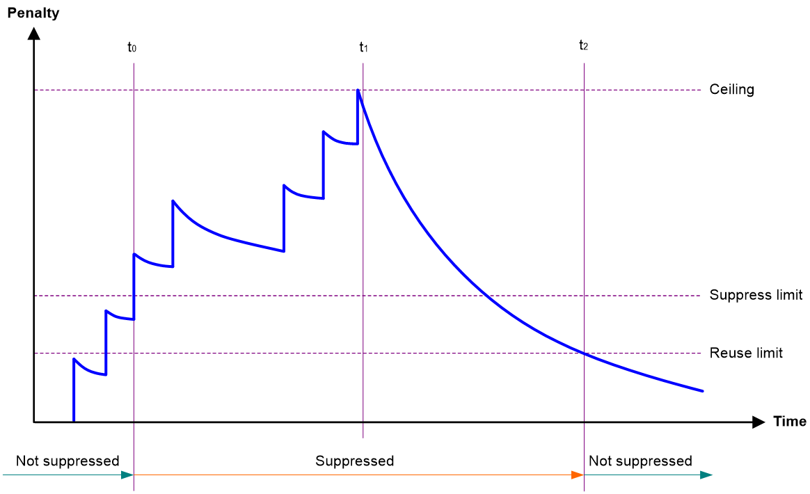
Parameters
· Penalty—The interface has an initial penalty of 0. When the interface flaps, the penalty increases by 1000 for each down event until the ceiling is reached. It does not increase for up events. When the interface stops flapping, the penalty decreases by half each time the half-life timer expires until the penalty drops to the reuse threshold.
· Ceiling—The penalty stops increasing when it reaches the ceiling.
· Suppress-limit—The accumulated penalty that triggers the device to dampen the interface. In dampened state, the interface does not report its state changes to the CPU. For state change events, the interface only generates SNMP traps and log messages.
· Reuse-limit—When the accumulated penalty decreases to this reuse threshold, the interface is not dampened. Interface state changes are reported to the upper layers. For each state change, the system also generates an SNMP trap and log message.
· Decay—The amount of time (in seconds) after which a penalty is decreased.
· Max-suppress-time—The maximum amount of time the interface can be dampened. If the penalty is still higher than the reuse threshold when this timer expires, the penalty stops increasing for down events. The penalty starts to decrease until it drops below the reuse threshold.
When configuring the dampening command, follow these rules to set the values mentioned above:
· The ceiling is equal to 2(Max-suppress-time/Decay) × reuse-limit. It is not user configurable.
· The configured suppress limit is lower than or equal to the ceiling.
· The ceiling is lower than or equal to the maximum suppress limit supported.
Figure 1 shows the change rule of the penalty value. The lines t0 and t2 indicate the start time and end time of the suppression, respectively. The period from t0 to t2 indicates the suppression period, t0 to t1 indicates the max-suppress-time, and t1 to t2 indicates the complete decay period.
Figure 1 Change rule of the penalty value
Restrictions and guidelines
· The dampening command does not take effect on the administratively down events. When you execute the shutdown command, the penalty restores to 0, and the interface reports the down event to the upper-layer protocols.
· Do not enable the dampening feature on an interface with spanning tree protocols enabled.
Procedure
1. Enter system view.
system-view
2. Enter Ethernet interface view.
interface interface-type interface-number
3. Enable dampening on the interface.
dampening [ half-life reuse suppress max-suppress-time ]
By default, interface dampening is disabled on Ethernet interfaces.
Configuring generic flow control on an Ethernet interface
About this task
To avoid dropping packets on a link, you can enable generic flow control at both ends of the link. When traffic congestion occurs at the receiving end, the receiving end sends a flow control (Pause) frame to ask the sending end to suspend sending packets. Generic flow control includes the following types:
· TxRx-mode generic flow control—Enabled by using the flow-control command. With TxRx-mode generic flow control enabled, an interface can both send and receive flow control frames:
¡ When congestion occurs, the interface sends a flow control frame to its peer.
¡ When the interface receives a flow control frame from its peer, it suspends sending packets to its peer.
· Rx-mode generic flow control—Enabled by using the flow-control receive enable command. With Rx-mode generic flow control enabled, an interface can receive flow control frames, but it cannot send flow control frames:
¡ When congestion occurs, the interface cannot send flow control frames to its peer.
¡ When the interface receives a flow control frame from its peer, it suspends sending packets to its peer.
To handle unidirectional traffic congestion on a link, configure the flow-control receive enable command at one end and the flow-control command at the other end. To enable both ends of a link to handle traffic congestion, configure the flow-control command at both ends.
Procedure
1. Enter system view.
system-view
2. Enter Ethernet interface view.
interface interface-type interface-number
3. Enable generic flow control.
¡ Enable TxRx-mode generic flow control.
flow-control
¡ Enable Rx-mode generic flow control.
flow-control receive enable
By default, generic flow control is disabled on an Ethernet interface.
Setting the statistics polling interval
About this task
To display the interface statistics collected in the last statistics polling interval, use the display interface command. To clear the interface statistics, use the reset counters interface command.
Setting the statistics polling interval in Ethernet interface view
1. Enter system view.
system-view
2. Enter Ethernet interface view.
interface interface-type interface-number
3. Set the statistics polling interval for the Ethernet interface.
flow-interval interval
By default, the statistics polling interval is 300 seconds.
Enabling loopback testing on an Ethernet interface
About this task
Perform this task to determine whether an Ethernet link works correctly.
Loopback testing includes the following types:
· Internal loopback testing—Tests the device where the Ethernet interface resides. The Ethernet interface sends outgoing packets back to the local device. If the device fails to receive the packets, the device fails.
· External loopback testing—Tests the inter-device link. The Ethernet interface sends incoming packets back to the remote device. If the remote device fails to receive the packets, the inter-device link fails.
Hardware and feature compatibility
|
Product series |
Model |
Product code |
Loopback testing compatibility |
|
WX1800H series |
WX1804H-PWR |
EWP-WX1804H-PWR-CN |
Yes |
|
WX2500H series |
WX2508H-PWR-LTE WX2510H-PWR WX2510H-F-PWR WX2540H WX2540H-F WX2560H |
EWP-WX2508H-PWR-LTE EWP-WX2510H-PWR EWP-WX2510H-F-PWR EWP-WX2540H EWP-WX2540H-F EWP-WX2560H |
No |
|
MAK series |
MAK204 MAK206 |
EWP-MAK204 EWP-MAK206 |
No |
|
WX3000H series |
WX3010H WX3010H-X-PWR WX3010H-L-PWR WX3024H WX3024H-L-PWR WX3024H-F |
EWP-WX3010H EWP-WX3010H-X-PWR EWP-WX3010H-L-PWR EWP-WX3024H EWP-WX3024H-L-PWR EWP-WX3024H-F |
Yes |
|
WX3500H series |
WX3508H WX3508H WX3510H WX3510H WX3520H WX3520H-F WX3540H WX3540H |
EWP-WX3508H EWP-WX3508H-F EWP-WX3510H EWP-WX3510H-F EWP-WX3520H EWP-WX3520H-F EWP-WX3540H EWP-WX3540H-F |
· Yes on service Ethernet interfaces · No on management Ethernet interfaces on WX3540H |
|
WX5500E series |
WX5510E WX5540E |
EWP-WX5510E EWP-WX5540E |
· Yes on service Ethernet interfaces · No on management Ethernet interfaces |
|
WX5500H series |
WX5540H WX5560H WX5580H |
EWP-WX5540H EWP-WX5560H EWP-WX5580H |
· Yes on service Ethernet interfaces · No on management Ethernet interfaces |
|
Access controller modules |
LSUM1WCME0 EWPXM1WCME0 LSQM1WCMX20 LSUM1WCMX20RT LSQM1WCMX40 LSUM1WCMX40RT EWPXM2WCMD0F EWPXM1MAC0F |
LSUM1WCME0 EWPXM1WCME0 LSQM1WCMX20 LSUM1WCMX20RT LSQM1WCMX40 LSUM1WCMX40RT EWPXM2WCMD0F EWPXM1MAC0F |
· No on service Ethernet interfaces · No on management Ethernet interfaces |
|
Product series |
Model |
Product code |
Loopback testing compatibility |
|
WX1800H series |
WX1804H-PWR WX1810H-PWR WX1820H WX1840H |
EWP-WX1804H-PWR EWP-WX1810H-PWR EWP-WX1820H EWP-WX1840H-GL |
Yes |
|
WX3800H series |
WX3820H WX3840H |
EWP-WX3820H-GL EWP-WX3840H-GL |
· Yes on service Ethernet interfaces · No on management Ethernet interfaces |
|
WX5800H series |
WX5860H |
EWP-WX5860H-GL |
· Yes on service Ethernet interfaces · No on management Ethernet interfaces |
Restrictions and guidelines
· After you enable this feature on an Ethernet interface, the interface does not forward data traffic.
· The shutdown and loopback commands are mutually exclusive.
· After you enable this feature on an Ethernet interface, the Ethernet interface switches to full duplex mode. After you disable this feature, the Ethernet interface restores to its duplex setting.
Procedure
1. Enter system view.
system-view
2. Enter Ethernet interface view.
interface interface-type interface-number
3. Enable loopback testing.
loopback{ external | internal }
Restoring the default settings for an interface
Restrictions and guidelines
|
|
CAUTION: This feature might interrupt ongoing network services. Make sure you are fully aware of the impacts of this feature when you use it in a live network. |
This feature might fail to restore the default settings for some commands because of command dependencies or system restrictions. You can use the display this command in interface view to check for these commands and perform their undo forms or follow the command reference to restore their default settings. If your restoration attempt still fails, follow the error message to resolve the problem.
Procedure
1. Enter system view.
system-view
2. Enter Ethernet interface view or Ethernet subinterface view.
interface interface-type { interface-number | interface-number.subnumber }
3. Restore the default settings for the interface.
default
Configuring a Layer 2 Ethernet interface
Configuring storm suppression
Hardware and feature compatibility
|
Hardware series |
Model |
Product code |
Feature compatibility |
|
WX1800H series |
WX1804H-PWR |
EWP-WX1804H-PWR-CN |
No |
|
WX2500H series |
WX2508H-PWR-LTE WX2510H-PWR WX2510H-F-PWR WX2540H WX2540H-F WX2560H |
EWP-WX2508H-PWR-LTE EWP-WX2510H-PWR EWP-WX2510H-F-PWR EWP-WX2540H EWP-WX2540H-F EWP-WX2560H |
No |
|
MAK series |
MAK204 MAK206 |
EWP-MAK204 EWP-MAK206 |
No |
|
WX3000H series |
WX3010H WX3010H-X-PWR WX3010H-L-PWR WX3024H WX3024H-L-PWR WX3024H-F |
EWP-WX3010H EWP-WX3010H-X-PWR EWP-WX3010H-L-PWR EWP-WX3024H EWP-WX3024H-L-PWR EWP-WX3024H-F |
Yes: · WX3010H · WX3024H · WX3024H-F No: · WX3010H-X-PWR · WX3010H-L-PWR · WX3024H-L-PWR |
|
WX3500H series |
WX3508H WX3508H WX3510H WX3510H WX3520H WX3520H-F WX3540H WX3540H |
EWP-WX3508H EWP-WX3508H-F EWP-WX3510H EWP-WX3510H-F EWP-WX3520H EWP-WX3520H-F EWP-WX3540H EWP-WX3540H-F |
No |
|
WX5500E series |
WX5510E WX5540E |
EWP-WX5510E EWP-WX5540E |
No |
|
WX5500H series |
WX5540H WX5560H WX5580H |
EWP-WX5540H EWP-WX5560H EWP-WX5580H |
No |
|
Access controller modules |
LSUM1WCME0 EWPXM1WCME0 LSQM1WCMX20 LSUM1WCMX20RT LSQM1WCMX40 LSUM1WCMX40RT EWPXM2WCMD0F EWPXM1MAC0F |
LSUM1WCME0 EWPXM1WCME0 LSQM1WCMX20 LSUM1WCMX20RT LSQM1WCMX40 LSUM1WCMX40RT EWPXM2WCMD0F EWPXM1MAC0F |
No |
|
Hardware series |
Model |
Product code |
Feature compatibility |
|
WX1800H series |
WX1804H-PWR WX1810H-PWR WX1820H WX1840H |
EWP-WX1804H-PWR EWP-WX1810H-PWR EWP-WX1820H EWP-WX1840H-GL |
No |
|
WX3800H series |
WX3820H WX3840H |
EWP-WX3820H-GL EWP-WX3840H-GL |
No |
|
WX5800H series |
WX5860H |
EWP-WX5860H-GL |
No |
About this task
The storm suppression feature ensures that the size of a particular type of traffic (broadcast, multicast, or unknown unicast traffic) does not exceed the threshold on an interface. When the broadcast, multicast, or unknown unicast traffic on the interface exceeds this threshold, the system discards packets until the traffic drops below this threshold.
Both storm suppression and storm control can suppress storms on an interface. Storm suppression uses the chip to suppress traffic. Storm suppression has less impact on the device performance than storm control, which uses software to suppress traffic.
Restrictions and guidelines
· The configured suppression threshold value in pps or kbps might be converted into a multiple of the step value supported by the chip. As a result, the effective suppression threshold might be different from the configured one. For information about the suppression threshold that takes effect, see the prompt on the device.
Procedure
system-view
2. Enter Ethernet interface view.
interface interface-type interface-number
3. Enable broadcast suppression and set the broadcast suppression threshold.
broadcast-suppression { ratio | pps max-pps | kbps max-kbps }
By default, broadcast suppression is disabled.
4. Enable multicast suppression and set the multicast suppression threshold.
multicast-suppression { ratio | pps max-pps | kbps max-kbps }
By default, multicast suppression is disabled.
5. Enable unknown unicast suppression and set the unknown unicast suppression threshold.
unicast-suppression { ratio | pps max-pps | kbps max-kbps }
By default, unknown unicast suppression is disabled.
Configuring a Layer 3 Ethernet interface or subinterface
Hardware compatibility with Layer 3 Ethernet interfaces or subinterfaces
|
Hardware series |
Models |
Product code |
Layer 3 Ethernet interface or subinterface compatibility |
|
WX1800H series |
WX1804H-PWR |
EWP-WX1804H-PWR-CN |
Yes |
|
WX2500H series |
WX2508H-PWR-LTE WX2510H-PWR WX2510H-F-PWR WX2540H WX2540H-F WX2560H |
EWP-WX2508H-PWR-LTE EWP-WX2510H-PWR EWP-WX2510H-F-PWR EWP-WX2540H EWP-WX2540H-F EWP-WX2560H |
Yes |
|
MAK series |
MAK204 MAK206 |
EWP-MAK204 EWP-MAK206 |
Yes |
|
WX3000H series |
WX3010H WX3010H-X-PWR WX3010H-L-PWR WX3024H WX3024H-L-PWR WX3024H-F |
EWP-WX3010H EWP-WX3010H-X-PWR EWP-WX3010H-L-PWR EWP-WX3024H EWP-WX3024H-L-PWR EWP-WX3024H-F |
Yes: · WX3010H · WX3024H · WX3024H-F No: · WX3010H-X-PWR · WX3010H-L-PWR · WX3024H-L-PWR |
|
WX3500H series |
WX3508H WX3508H WX3510H WX3510H WX3520H WX3520H-F WX3540H WX3540H |
EWP-WX3508H EWP-WX3508H-F EWP-WX3510H EWP-WX3510H-F EWP-WX3520H EWP-WX3520H-F EWP-WX3540H EWP-WX3540H-F |
No |
|
WX5500E series |
WX5510E WX5540E |
EWP-WX5510E EWP-WX5540E |
No |
|
WX5500H series |
WX5540H WX5560H WX5580H |
EWP-WX5540H EWP-WX5560H EWP-WX5580H |
No |
|
Access controller modules |
LSUM1WCME0 EWPXM1WCME0 LSQM1WCMX20 LSUM1WCMX20RT LSQM1WCMX40 LSUM1WCMX40RT EWPXM2WCMD0F EWPXM1MAC0F |
LSUM1WCME0 EWPXM1WCME0 LSQM1WCMX20 LSUM1WCMX20RT LSQM1WCMX40 LSUM1WCMX40RT EWPXM2WCMD0F EWPXM1MAC0F |
No |
|
Hardware series |
Models |
Product code |
Layer 3 Ethernet interface or subinterface compatibility |
|
WX1800H series |
WX1804H-PWR WX1810H-PWR WX1820H WX1840H |
EWP-WX1804H-PWR EWP-WX1810H-PWR EWP-WX1820H EWP-WX1840H-GL |
Yes |
|
WX3800H series |
WX3820H WX3840H |
EWP-WX3820H-GL EWP-WX3840H-GL |
No |
|
WX5800H series |
WX5860H |
EWP-WX5860H-GL |
No |
Setting the MTU for an Ethernet interface or subinterface
Restrictions and guidelines
The maximum transmission unit (MTU) of an Ethernet interface affects the fragmentation and reassembly of IP packets on the interface. Typically, you do not need to modify the MTU of an interface.
Procedure
1. Enter system view.
system-view
2. Enter interface view.
interface interface-type { interface-number | interface-number.subnumber }
3. Set the interface MTU.
mtu size
The default setting varies by device model. For more information, see the command reference.
Setting the MAC address of an Ethernet interface or subinterface
About this task
In a network, when the Layer 3 Ethernet interfaces or subinterfaces of different devices have the same MAC address, the devices might fail to communicate correctly. To eliminate the MAC address conflicts, use the mac-address command to modify the MAC addresses of Layer 3 Ethernet interfaces or subinterfaces.
Additionally, when a Layer 3 Ethernet subinterface is created, it uses the MAC address of its main interface by default. As a result, all Layer 3 Ethernet subinterfaces of a Layer 3 Ethernet interface share the same MAC address. To set a different MAC address for a Layer 3 Ethernet subinterface, use the mac-address command.
Procedure
1. Enter system view.
system-view
2. Enter interface view.
interface interface-type { interface-number | interface-number.subnumber }
3. Set the interface MAC address.
mac-address mac-address
By default, no MAC address is set for a Layer 3 Ethernet interface.
Display and maintenance commands
|
|
IMPORTANT: The WX1800H series, WX2500H series, MAK series, and WX3000H series access controllers do not support parameters or commands that are available only in IRF mode. |
Execute display commands in any view and reset commands in user view.
|
Task |
Command |
|
Display interface traffic statistics. |
display counters { inbound | outbound } interface [ interface-type [ interface-number | interface-number.subnumber ] ] |
|
Display traffic rate statistics of interfaces in up state over the last statistics polling interval. |
display counters rate { inbound | outbound } interface [ interface-type [ interface-number | interface-number.subnumber ] ] |
|
Display the Ethernet module statistics. |
In standalone mode: display ethernet statistics In IRF mode: display ethernet statistics slot slot-number |
|
Display the operational and status information of the specified interfaces. |
display interface [ interface-type [ interface-number | interface-number.subnumber ] ] [ brief [ description | down ] ] |
|
Display information about dropped packets on the specified interfaces. |
display packet-drop { interface [ interface-type [ interface-number ] ] | summary } |
|
Clear interface statistics. |
reset counters interface [ interface-type [ interface-number | interface-number.subnumber ] ] |
|
Clear the Ethernet module statistics. |
In standalone mode: reset ethernet statistics In IRF mode: reset ethernet statistics [ slot slot-number ] |
|
Clear the statistics of dropped packets on the specified interfaces. |
reset packet-drop interface [ interface-type [ interface-number ] ] |