- Table of Contents
- Related Documents
-
| Title | Size | Download |
|---|---|---|
| 03-Data buffer configuration | 161.59 KB |
Contents
Restrictions and guidelines: Data buffer configuration
Configuring data buffers manually
Setting the buffer ratio or size for a queue in interface view
Setting the fixed-area ratio or size for a queue
Setting the maximum shared-area ratio or size for a queue
Mapping a queue to a service pool
Configuring data buffer monitoring
Configuring data buffer alarms
Configuring alarm thresholds for the ingress or egress buffer
Configuring alarm thresholds for the Headroom buffer
Configuring packet-drop alarms
Display and maintenance commands for data buffers
Restrictions and guidelines: TCB configuration
Enabling and configuring TCB in system view
Enabling and configuring TCB in interface view
Display and maintenance commands for TCB
Example: Configuring TCB on an interface
Configuring data buffers
About data buffers
Data buffer types
Data buffers temporarily store packets to avoid packet loss.
The following data buffers are available:
· Ingress buffer—Stores incoming packets when the CPU is busy.
· Egress buffer—Stores outgoing packets when network congestion occurs.
· Headroom buffer—Stores packets when the ingress buffer or egress buffer is used up.
Figure 1 shows the structure of ingress and egress buffers.
Figure 1 Data buffer structure

Cell resources
A buffer uses cell resources to store packets based on packet sizes. A cell resource is 256 bytes. The buffer allocates one cell resource to a 128-byte packet and two cell resources to a 300-byte packet.
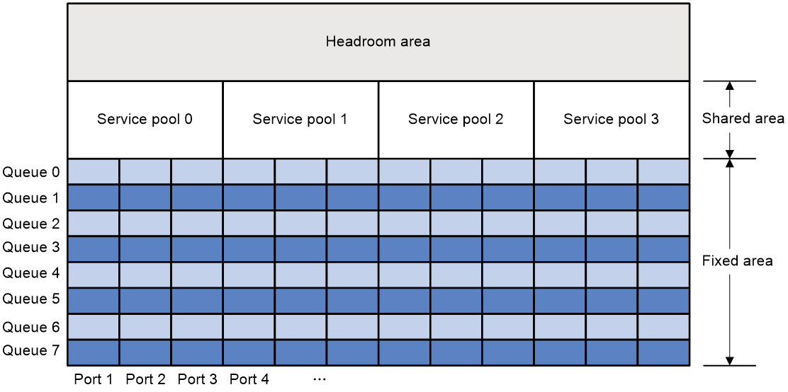
Fixed area and shared area
The cell resources have a fixed area and a shared area.
· Fixed area—Partitioned into queues, each of which is equally divided by all the interfaces on the switch, as shown in Figure 2. When congestion occurs or the CPU is busy, the following rules apply:
a. An interface first uses the relevant queues of the fixed area to store packets.
b. When a queue is full, the interface uses the corresponding queue of the shared area.
c. When the queue in the shared area is also full, the interface discards subsequent packets.
The system allocates the fixed area among queues as specified by the user. Even if a queue is not full, other queues cannot preempt its space. Similarly, the share of a queue for an interface cannot be preempted by other interfaces even if it is not full.
· Shared area—Partitioned into queues, each of which is not equally divided by the interfaces, as shown in Figure 2. The system determines the actual shared-area space for each queue according to user configuration and the number of packets actually received and sent. If a queue is not full, other queues can preempt its space.
The system puts packets received or sent on all interfaces into a queue in the order they arrive. When the queue is full, subsequent packets are dropped.
The shared area is also divided into service pools based on application services. You can map a queue to a service pool, and this queue can only use the resources of that service pool. By default, all of the shared area belongs to service pool 0.
Figure 2 Fixed area and shared area
Restrictions and guidelines: Data buffer configuration
You can configure data buffers either manually or automatically by enabling the Burst feature. If you have configured data buffers in one way, delete the configuration before using the other way. Otherwise, the new configuration does not take effect.
Inappropriate data buffer changes can cause system problems. Before manually changing data buffer settings, make sure you understand its impact on your device. As a best practice, use the burst-mode enable command if the system requires large buffer spaces.
Please manually configure the data buffers, set the buffer ratios or sizes for queues, and map queues to service pools before the device receives and forwards packets. If you perform these tasks when the device is forwarding packets, packets might be lost.
Data buffer tasks at a glance
To configure the data buffer, perform the following tasks:
· Configuring data buffers manually
· Setting the buffer ratio or size for a queue in interface view
¡ Setting the fixed-area ratio or size for a queue
¡ Setting the maximum shared-area ratio or size for a queue
· Mapping a queue to a service pool
· (Optional.) Configuring data buffer monitoring
· (Optional.) Configuring data buffer alarms
¡ Configuring alarm thresholds for the ingress or egress buffer
¡ Configuring alarm thresholds for the Headroom buffer
¡ Configuring packet-drop alarms
Enabling the Burst feature
About this task
The Burst feature enables the device to automatically allocate cell and packet resources. It is well suited to the following scenarios:
· Broadcast or multicast traffic is intensive, resulting in bursts of traffic.
· Traffic comes in and goes out in one of the following ways:
¡ Enters a device from a high-speed interface and goes out of a low-speed interface.
¡ Enters from multiple same-rate interfaces at the same time and goes out of an interface with the same rate.
The default data buffer settings are changed after the Burst feature is enabled. You can display the data buffer settings by using the display buffer command.
Procedure
1. Enter system view.
system-view
2. Enable the Burst feature.
burst-mode enable
By default, the Burst feature is disabled.
Configuring data buffers manually
About this task
Each type of resources of a buffer, packet or cell, has a fixed size. After you set the shared-area size for a type of resources, the rest is automatically assigned to the fixed area.
By default, all queues have an equal share of the shared area and the fixed area. You can change the maximum shared-area space and the fixed-area for a queue. The unconfigured queues use the default settings.
Procedure
1. Enter system view.
system-view
2. Configure buffer assignment rules. Choose the options to configure as needed:
¡ Set the total shared-area ratio.
buffer egress [ slot slot-number ] cell total-shared ratio ratio
The default setting is 100%.
¡ Set the maximum shared-area ratio for a queue.
buffer egress [ slot slot-number ] cell queue queue-id shared { ratio ratio | size }
The default setting is 20%.
The actual maximum shared-area space for each queue is determined based on your configuration and the number of packets to be received and sent.
The buffer egress [ slot slot-number ] cell queue queue-id shared size command must be used together with PFC. If you do not use PFC, do not execute this command. For more information about PFC, see Ethernet interface configuration in Layer 2—LAN Switching Configuration Guide.
The size argument is supported only in Release 6616 and later.
¡ Set the fixed-area ratio for a queue.
buffer egress [ slot slot-number ] cell queue queue-id guaranteed ratio ratio
The sum of fixed-area ratios configured for all queues cannot exceed the total fixed-area ratio. Otherwise, the configuration fails.
¡ Set the fixed-area ratio or size for a service pool.
buffer { egress | ingress } [ slot slot-number ] cell service-pool sp-id shared ratio ratio
By default, all of the shared area is reserved for service pool 0.
3. Apply buffer assignment rules.
buffer apply
You cannot directly modify the applied configuration. To modify the configuration, you must cancel the application, reconfigure data buffers, and reapply the configuration.
Setting the buffer ratio or size for a queue in interface view
Setting the fixed-area ratio or size for a queue
About this task
The fixed area is partitioned into queues, each of which is equally divided by all the interfaces. Even if a queue is not full, other queues cannot preempt its space. After you set the fixed-area ratio for a queue, the other queues have an equal share of the remaining part.
Restrictions and guidelines
The sum of the fixed-area ratios configured for all queues cannot exceed 100%. The queue that causes the sum of the fixed-area ratios to exceed 100% fails to be configured and still uses the default setting.
The fixed-area ratio setting in interface view has higher priority than the fixed-area ratio setting in system view. If it is configured in both views, the setting in interface view takes effect.
Procedure
1. Enter system view.
system-view
2. Enter interface view.
interface interface-type interface-number
3. Set the fixed-area ratio or size for a queue.
buffer egress cell queue queue-id guaranteed ratio ratio
The default setting is 13%.
Setting the maximum shared-area ratio or size for a queue
About this task
The shared area is partitioned into queues. If a queue is not full, other queues can preempt its space.. After you set the maximum shared-area ratio for a queue, the other queues use the default setting. The system determines the actual shared-area space for each queue according to user configuration and the number of packets actually received and sent.
Restrictions and guidelines
The maximum shared-area ratio setting in interface view has higher priority than the maximum shared-area setting in system view. If it is configured in both views, the setting in interface view takes effect.
Procedure
1. Enter system view.
system-view
2. Enter interface view.
interface interface-type interface-number
3. Set the maximum shared-area ratio or size for a queue.
buffer egress cell queue queue-id shared ratio ratio
The default setting is 20 %.
The buffer egress cell queue queue-id shared size command must be used together with PFC. If you do not use PFC, do not execute this command. For more information about PFC, see Ethernet interface configuration in Layer 2—LAN Switching Configuration Guide.
The size argument is supported only in Release 6616 and later.
Mapping a queue to a service pool
About this task
A queue mapped to a service pool can only use that service pool to store packets and does not affect other service pools.
For the ingress buffer, the queue ID specified represents the 802.1p priority in packets.
Prerequisites
Before performing this task, use the buffer service-pool shared command to set the maximum shared-area ratio for the service pool.
Procedure
1. Enter system view.
system-view
2. Enter interface view.
interface interface-type interface-number
3. Map a queue to a service pool.
buffer { egress | ingress } queue queue-id map-to service-pool sp-id
By default, all queues are mapped to service pool 0.
Configuring data buffer monitoring
About this task
The data buffer on a switch is shared by all interfaces for buffering packets during periods of congestion.
This feature allows you to identify the interfaces that use an excessive amount of data buffer space. Then, you can diagnose those interfaces for anomalies.
You can set a per-interface buffer usage threshold. The buffer usage threshold for a queue is the same as the per-interface threshold value. The switch automatically records buffer usage for each interface. When a queue on an interface uses more buffer space than the set threshold, the system counts one threshold violation for the queue.
Procedure
1. Enter system view.
system-view
2. Set a per-interface buffer usage threshold.
buffer usage threshold slot slot-number ratio ratio
The default setting is 70%.
Configuring data buffer alarms
About data buffer alarms
This feature works with a network management system (such as IMC). Data buffer alarms include threshold-crossing alarms and packet drop alarms. The device reports these alarms to the network management system for displaying the data buffer usage.
Configuring alarm thresholds for the ingress or egress buffer
1. Enter system view.
system-view
2. Configure the alarm thresholds. Choose the options to configure as needed:
¡ Configure the global alarm threshold for a queue.
buffer { egress | ingress } usage threshold slot slot-number queue queue-id ratio ratio
The default setting is 100%.
¡ Execute the following commands in sequence to configure the alarm threshold for a queue on an interface:
interface interface-type interface-number
buffer { egress | ingress } usage threshold queue queue-id ratio ratio
The default setting is 100%.
3. Enable threshold-crossing alarms.
buffer threshold alarm { egress | ingress } enable
By default, threshold-crossing alarms are disabled.
4. (Optional.) Set the interval for sending threshold-crossing alarms.
buffer threshold alarm { egress | ingress } interval interval
By default, the global alarm threshold is used.
Configuring alarm thresholds for the Headroom buffer
1. Enter system view.
system-view
2. Configure the alarm thresholds. Choose the options to configure as needed:
¡ Configure the global per-queue alarm threshold.
buffer usage threshold headroom slot slot-number ratio ratio
The default setting is 100%.
¡ Execute the following commands in sequence to configure the alarm threshold for a queue on an interface:
interface interface-type interface-number
buffer usage threshold headroom queue queue-id ratio ratio
By default, the global per-queue alarm threshold is used.
3. Enable threshold-crossing alarms.
buffer threshold alarm headroom enable
By default, threshold-crossing alarms are disabled.
4. (Optional.) Set the interval for sending threshold-crossing alarms.
buffer threshold alarm headroom interval interval
The default setting is 5 seconds.
Configuring packet-drop alarms
About this task
This feature allows the device to periodically send packet-drop information to the NMS.
Restrictions and guidelines
This feature does not take effect on the Headroom buffer.
Procedure
1. Enter system view.
system-view
2. Enable packet-drop alarms.
buffer packet-drop alarm enable
By default, packet-drop alarms are disabled.
3. (Optional.) Set the interval for sending packet-drop alarms.
buffer packet-drop alarm interval interval
The default setting is 5 seconds.
Display and maintenance commands for data buffers
Execute display commands in any view.
|
Task |
Command |
|
Display buffer size settings. |
display buffer [ slot slot-number ] [ queue [ queue-id ] ] |
|
Display data buffer usage. |
display buffer usage [ slot slot-number ] |
|
Display buffer usage statistics for interfaces. |
display buffer usage interface [ interface-type [ interface-number ] ] [ verbose ] |
Configuring TCB
About TCB
Overview
The Transient Capture Buffer (TCB) feature monitors packet drop events on a set of memory management unit (MMU) resources. When a packet is dropped on a queue, the system collects drop time, drop reason, packet metadata, and other information and reports them to an NMS through gRPC.
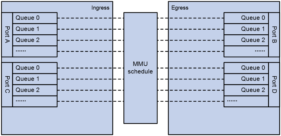
An MMU manages the allocation of the ingress buffer and egress buffer and flexibly schedules queues to deal with traffic bursts.
Figure 3 MMU queues
How TBC works
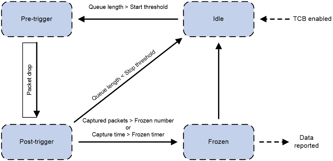
The TCB state machine works as follows:
1. The state machine enters the idle state when TCB is enabled.
2. When the queue length is greater than start-threshold-value, the state machine transitions from the idle state to the pre-trigger state. The system captures packets by using the pre-sample-rate.
3. When packet drops occur on the queue, the state machine transitions from the pre-trigger to the post-trigger state.
4. When the queue length is smaller than stop-threshold-value, the state machine transitions from the post-trigger to the idle state. The system stops capturing packets.
5. When the queue length is greater than start-threshold-value, step 2 is repeated.
6. When the number of captured packets reaches the frozen-number or the capture timer expires, the state machine transitions from the post-trigger to the frozen state.
7. The state machine analyzes the drop reason and dropped packet characteristics and sends the analysis results to the gRPC module, which reports them to an NMS.
8. The state machine transitions from the frozen to the idle state.
Figure 4 TCB state machine
Restrictions and guidelines: TCB configuration
You can configure TCB in system view or interface view, but not in both views at the same time. For example, if you have configured TCB in system view, to configure TCB in interface view, you must first delete the TCB configuration in system view.
The TCB configuration in system view takes effect on all TCB-capable interfaces. The TCB configuration in interface view takes effect only on the specified interface.
In interface view, only one interface on the device can be configured with TCB.
The gRPC sampling paths for TCB are tcb/tcbpacketinfoevent and tcb/tcbrawpacketinfoevent. The data collected by TCB is reported by gRPC to the collector. For more information about gRPC, see "Configuring gRPC."
If TCB is configured on a VTEP in a VXLAN network to monitor packets to site networks, it obtains outer header information instead of inner header information of VXLAN packets as the packet characteristics.
Enabling and configuring TCB
Enabling and configuring TCB in system view
Software version and feature compatibility
This feature is supported only in Release 6616 and later.
Procedure
1. Enter system view.
system-view
2. Enable and configure TCB.
buffer transient-capture global [ slot slot-number ] egress enable [ no-local-analysis ] [ acl { ipv4-acl-number | name ipv4-acl-name } ] [ start-threshold start-threshold-value stop-threshold stop-threshold-value ] [ frozen-number frozen-number frozen-timer timer-value ] [ pre-sample-rate pre-sample-rate post-sample-rate post-sample-rate ] [ poll-frequency frequency-value ]
By default, TCB is disabled.
Enabling and configuring TCB in interface view
1. Enter system view.
system-view
2. Enter interface view.
interface interface-type interface-number
3. Enable and configure TCB.
buffer transient-capture { egress [ queue queue-id ] | ingress } enable [ no-local-analysis ] [ acl { ipv4-acl-number | name ipv4-acl-name } ] [ start-threshold start-threshold-value stop-threshold stop-threshold-value ] [ frozen-number frozen-number frozen-timer timer-value ] [ pre-sample-rate pre-sample-rate post-sample-rate post-sample-rate ] [ poll-frequency frequency-value ]
By default, TCB is disabled.
Display and maintenance commands for TCB
|
|
IMPORTANT: The display buffer transient-capture packet-drop command is supported only in Release 6616 and later. |
Execute display commands in any view.
|
Task |
Command |
|
Display packet drop information. |
display buffer transient-capture packet-drop slot slot-number { ethernet | ipv4 | ipv6 } |
TCB configuration examples
Example: Configuring TCB on an interface
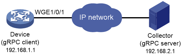
Network configuration
As shown in Figure 5, configure TCB and gRPC on the device to monitor packet drops and report packet drop information to the collector through gRPC.
Procedure
1. Assign IP addresses to the device and the collector and configure routes. Make sure the network connections are available. (Details not shown.)
2. Configure TCB:
# Create an IPv4 advanced ACL numbered 3001, and configure a rule to match packets with source IP address 192.168.5.2.
<Device> system-view
[Device] acl advanced 3001
[Device-acl-ipv4-adv-3001] rule permit ip source 192.168.5.2 0
[Device-acl-ipv4-adv-3001] quit
# Configure TCB on Twenty-FiveGigE 1/0/1.
[Device] interface twenty-fivegige 1/0/1
[Device-Twenty-FiveGigE1/0/1] buffer transient-capture egress queue 1 enable no-local-analysis acl 3001 start-threshold 10000 stop-threshold 5000 frozen-number 1000 frozen-timer 500 pre-sample-rate 10 post-sample-rate 10 poll-frequency 600
[Device-Twenty-FiveGigE1/0/1] quit
3. Configure gRPC:
# Enable the gRPC service.
[Device] grpc enable
# Create a sensor group named test, and add sensor paths tcb/tcbpacketinfoevent and tcb/tcbrawpacketinfoevent.
[Device] telemetry
[Device-telemetry] sensor-group test
[Device-telemetry-sensor-group-test] sensor path tcb/tcbpacketinfoevent
[Device-telemetry-sensor-group-test] sensor path tcb/tcbrawpacketinfoevent
[Device-telemetry-sensor-group-test] quit
# Create a destination group named collector1. Specify a collector that uses IPv4 address 192.168.2.1 and port number 50050.
[Device-telemetry] destination-group collector1
[Device-telemetry-destination-group-collector1] ipv4-address 192.168.2.1 port 50050
[Device-telemetry-destination-group-collector1] quit
# Configure a subscription named A to bind sensor group test with destination group collector1. Set the sampling interval to 10 seconds.
[Device-telemetry] subscription A
[Device-telemetry-subscription-A] sensor-group test sample-interval 10
[Device-telemetry-subscription-A] destination-group collector1
[Device-telemetry-subscription-A] quit
[Device-telemetry] quit
Verifying the configuration
# Verify that the collector receives packet drop information when packet drops occur on a queue enabled with TCB. (Details not shown.)