- Table of Contents
- Related Documents
-
| Title | Size | Download |
|---|---|---|
| 02-QoS configuration | 810.33 KB |
Contents
QoS processing flow in a device
Restrictions and guidelines: QoS policy configuration
Restrictions and guidelines for applying a QoS policy
Applying the QoS policy to an Ethernet service instance
Applying the QoS policy to an interface
Applying the QoS policy to VLANs
Applying the QoS policy globally
Applying the QoS policy to a control plane
Applying the QoS policy to a user profile
Display and maintenance commands for QoS policies
QoS policy configuration examples
Example: Applying multiple QoS policies to the inbound direction of an interface
Priority mapping configuration methods
Priority mapping tasks at a glance
Configuring a port to trust packet priority for priority mapping
Changing the port priority of an interface
Display and maintenance commands for priority mapping
Priority mapping configuration examples
Example: Configuring a priority trust mode
Example: Configuring priority mapping tables and priority marking
Configuring traffic policing, GTS, and rate limit
About traffic policing, GTS, and rate limit
Traffic evaluation and token buckets
Restrictions and guidelines: Traffic policing, GTS, and rate limit configuration
Display and maintenance commands for traffic policing, GTS, and rate limit
Traffic policing, GTS, and rate limit configuration examples
Example: Configuring traffic policing and GTS
Configuring congestion management
Cause, negative results, and countermeasure of congestion
Congestion management tasks at a glance
Configuring queuing on an interface
Restrictions and guidelines for queuing configuration
Configuring a queue scheduling profile
About queue scheduling profiles
Restrictions and guidelines for queue scheduling profile configuration
Configuring a queue scheduling profile
Applying a queue scheduling profile
Example: Configuring a queue scheduling profile
Display and maintenance commands for congestion management
Configuring congestion avoidance
Relationship between WRED and queuing mechanisms
Restrictions and guidelines: WRED configuration
Configuring WRED parameters for a queue
Configuring and applying a queue-based WRED table
Example: Configuring and applying a queue-based WRED table
Enabling global WRED Smart ECN
Display and maintenance commands for WRED
Restrictions and guidelines: Traffic filtering configuration
Traffic filtering configuration examples
Example: Configuring traffic filtering
Example: Configuring traffic filtering with the none action
Priority marking configuration examples
Example: Configuring priority marking
Restrictions and guidelines: Nesting configuration
Nesting configuration examples
Configuring traffic redirecting
Restrictions and guidelines: Traffic redirecting configuration
Traffic redirecting configuration examples
Example: Configuring traffic redirecting
Restrictions and guidelines: Aggregate CAR configuration
Display and maintenance commands for aggregate CAR
Distinguishing elephant and mice flows
Restrictions: Software version compatibility with distinguishing elephant and mice flows
Restrictions and guidelines: Elephant and mice flow distinguishing configuration
Configuring interface packet accounting
About interface packet accounting
Restrictions: Software version compatibility with interface packet accounting
Restrictions and guidelines: Interface packet accounting configuration
Display and maintenance commands for interface packet accounting
Configuring class-based accounting
Class-based accounting configuration examples
Example: Configuring class-based accounting
Configuring basic BGP functions
Configuring the route receiver
Configuring basic BGP functions
Enabling QPPB on the route receiving interface
Example: Configuring QPPB in an IPv4 network
Example: Configuring QPPB in an MPLS L3VPN
Example: Configuring QPPB in an IPv6 network
Configuring packet-drop logging for control plane protocols
About packet-drop logging for control plane protocols
Appendix B Default priority maps
Appendix C Introduction to packet precedence
QoS overview
In data communications, Quality of Service (QoS) provides differentiated service guarantees for diversified traffic in terms of bandwidth, delay, jitter, and drop rate, all of which can affect QoS.
QoS manages network resources and prioritizes traffic to balance system resources.
The following section describes typical QoS service models and widely used QoS techniques.
QoS service models
This section describes several typical QoS service models.
Best-effort service model
The best-effort model is a single-service model. The best-effort model is not as reliable as other models and does not guarantee delay-free delivery.
The best-effort service model is the default model for the Internet and applies to most network applications. It uses the First In First Out (FIFO) queuing mechanism.
IntServ model
The integrated service (IntServ) model is a multiple-service model that can accommodate diverse QoS requirements. This service model provides the most granularly differentiated QoS by identifying and guaranteeing definite QoS for each data flow.
In the IntServ model, an application must request service from the network before it sends data. IntServ signals the service request with the RSVP. All nodes receiving the request reserve resources as requested and maintain state information for the application flow.
The IntServ model demands high storage and processing capabilities because it requires all nodes along the transmission path to maintain resource state information for each flow. This model is suitable for small-sized or edge networks. However, it is not suitable for large-sized networks, for example, the core layer of the Internet, where billions of flows are present.
DiffServ model
The differentiated service (DiffServ) model is a multiple-service model that can meet diverse QoS requirements. It is easy to implement and extend. DiffServ does not signal the network to reserve resources before sending data, as IntServ does.
QoS techniques in a network
The QoS techniques include the following features:
· Traffic classification.
· Traffic policing.
· Traffic shaping.
· Rate limit.
· Congestion management.
· Congestion avoidance.
The following section briefly introduces these QoS techniques.
All QoS techniques in this document are based on the DiffServ model.
Figure 1 Position of the QoS techniques in a network
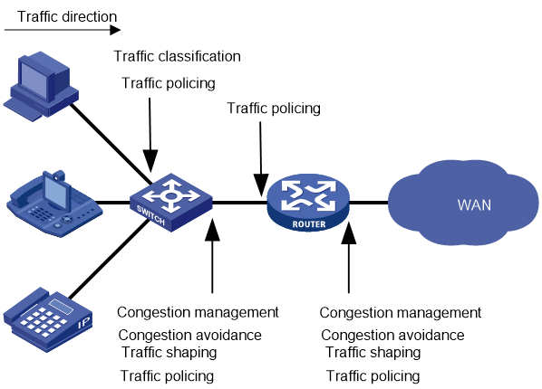
As shown in Figure 1, traffic classification, traffic shaping, traffic policing, congestion management, and congestion avoidance mainly implement the following functions:
· Traffic classification—Uses match criteria to assign packets with the same characteristics to a traffic class. Based on traffic classes, you can provide differentiated services.
· Traffic policing—Polices flows and imposes penalties to prevent aggressive use of network resources. You can apply traffic policing to both incoming and outgoing traffic of a port.
· Traffic shaping—Adapts the output rate of traffic to the network resources available on the downstream device to eliminate packet drops. Traffic shaping usually applies to the outgoing traffic of a port.
· Congestion management—Provides a resource scheduling policy to determine the packet forwarding sequence when congestion occurs. Congestion management usually applies to the outgoing traffic of a port.
· Congestion avoidance—Monitors the network resource usage. It is usually applied to the outgoing traffic of a port. When congestion worsens, congestion avoidance reduces the queue length by dropping packets.
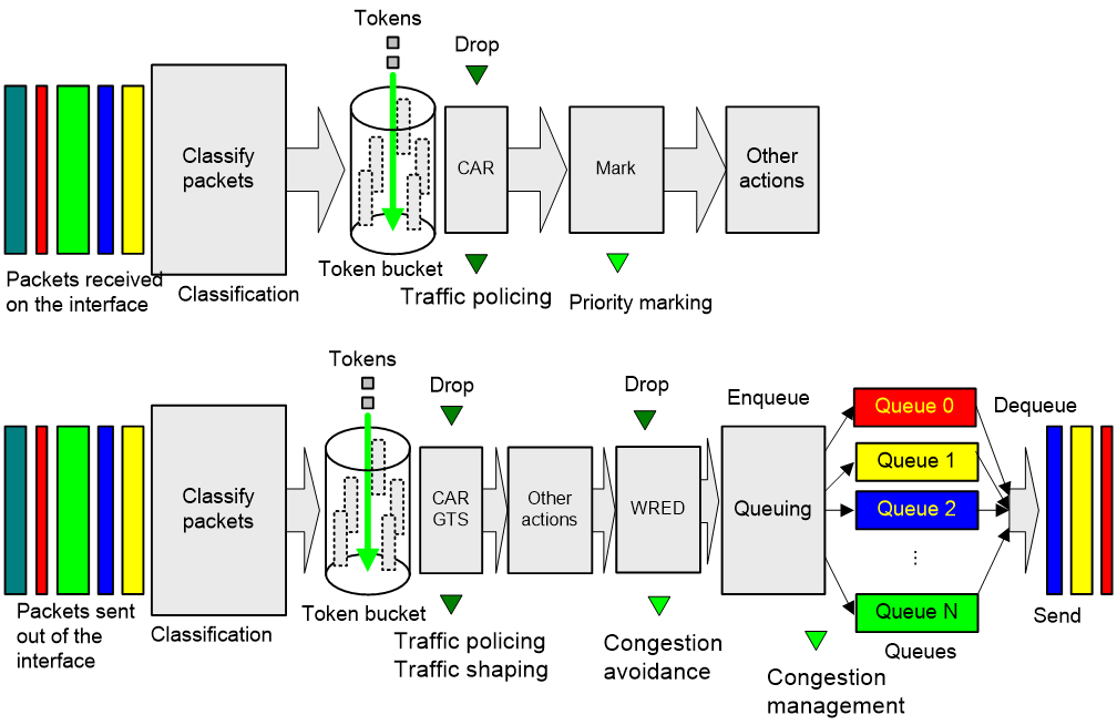
QoS processing flow in a device
Figure 2 briefly describes how the QoS module processes traffic.
1. Traffic classifier identifies and classifies traffic for subsequent QoS actions.
2. The QoS module takes various QoS actions on classified traffic as configured, depending on the traffic processing phase and network status. For example, you can configure the QoS module to perform the following operations:
¡ Traffic policing for incoming traffic.
¡ Traffic shaping for outgoing traffic.
¡ Congestion avoidance before congestion occurs.
¡ Congestion management when congestion occurs.
QoS configuration approaches
You can configure QoS by using the MQC approach or non-MQC approach.
In the modular QoS configuration (MQC) approach, you configure QoS service parameters by using QoS policies. A QoS policy defines QoS actions to take on different classes of traffic and can be applied to an object (such as an interface) to control traffic.
In the non-MQC approach, you configure QoS service parameters without using a QoS policy. For example, you can use the rate limit feature to set a rate limit on an interface without using a QoS policy.
Some features support both approaches, but some support only one.
Configuring a QoS policy
About QoS policies
A QoS policy has the following components:
· Traffic class—Defines criteria to match packets.
· Traffic behavior—Defines QoS actions to take on matching packets.
By associating a traffic class with a traffic behavior, a QoS policy can perform the QoS actions on matching packets.
A QoS policy can have multiple class-behavior associations.
Restrictions and guidelines: QoS policy configuration
The switch supports the following QoS policy types:
· Generic—Can be applied to all supported destinations and can contain all actions.
· Accounting—Can be applied to only interfaces or globally and can contain only class-based accounting actions.
· Mirroring—Can be applied to only interfaces or globally and can contain only class-based mirroring actions.
· Marking—Can be applied to only interfaces or globally and can contain only class-based marking actions.
If you do not specify the accounting, mirroring, remarking, or tap keyword when creating a QoS policy, a generic QoS policy is created.
QoS policies of different types cannot have the same policy name.
A maximum of four QoS policies (one for each type) can be applied to one direction of an interface. Different actions can be taken on the same traffic class if QoS policies of different types are applied to an interface.
Only one generic QoS policy can be applied to the outbound direction of an interface.
A QoS policy that contains an action of mirroring packets to the INT processor can only be applied to the inbound direction of an interface and does not support the share-mode keyword.
QoS policy tasks at a glance
To configure a QoS policy, perform the following tasks:
2. Defining a traffic behavior
¡ Applying the QoS policy to an Ethernet service instance
¡ Applying the QoS policy to an interface
¡ Applying the QoS policy to VLANs
¡ Applying the QoS policy globally
¡ Applying the QoS policy to a control plane
¡ Applying the QoS policy to a user profile
Defining a traffic class
Restrictions and guidelines
In a QoS policy applied to the outbound direction of an interface, a match criterion without IPv6 attributes cannot match IPv6 packets. For example, a source MAC address or Layer 2 ACL match criterion cannot match IPv6 packets.
Procedure
1. Enter system view.
system-view
2. Create a traffic class and enter traffic class view.
traffic classifier classifier-name [ operator { and | or } ]
3. (Optional.) Configure a description for the traffic class.
description text
By default, no description is configured for a traffic class.
4. Configure a match criterion.
if-match match-criteria
By default, no match criterion is configured.
For more information, see the if-match command in ACL and QoS Command Reference.
Defining a traffic behavior
1. Enter system view.
system-view
2. Create a traffic behavior and enter traffic behavior view.
traffic behavior behavior-name
3. Configure an action in the traffic behavior.
By default, no action is configured for a traffic behavior.
For more information about configuring an action, see the subsequent chapters for traffic policing, traffic filtering, priority marking, class-based accounting, and so on.
Defining a QoS policy
1. Enter system view.
system-view
2. Create a QoS policy and enter QoS policy view.
qos [ ipv6-matching | { accounting | mirroring | remarking } ] policy policy-name
|
Parameter |
Description |
|
ipv6-matching |
Represents an IPv6-matching QoS policy. |
|
accounting |
Represents an accounting-type QoS policy. |
|
mirroring |
Represents a mirroring-type QoS policy. |
|
remarking |
Represents a marking-type QoS policy. |
3. Associate a traffic class with a traffic behavior to create a class-behavior association in the QoS policy.
classifier classifier-name behavior behavior-name [ mode { dcbx | loose | qppb-manipulation } | insert-before before-classifier-name ] *
By default, a traffic class is not associated with a traffic behavior.
Repeat this step to create more class-behavior associations.
|
Parameter |
Description |
|
dcbx |
Specifies that a class-behavior association applies only to DCBX. For more information about DCBX, see Layer 2—LAN Switching Configuration Guide. |
|
loose |
Specifies that a class-behavior association applies only to a QoS policy applied to a control plane. |
|
qppb-manipulation |
Specifies that a class-behavior association applies only to matching the apply qos-local-id command configuration in a BGP routing policy. For more information, see Layer 3—IP Routing Configuration Guide. |
Applying the QoS policy
Application destinations
You can apply a QoS policy to the following destinations:
· Ethernet service instance—The QoS policy takes effect on the traffic sent or received on the Ethernet service instance.
· Interface—The QoS policy takes effect on the traffic sent or received on the interface.
· VLAN—The QoS policy takes effect on the traffic sent or received on all ports in the VLAN.
· Globally—The QoS policy takes effect on the traffic sent or received on all ports.
· Control plane—The QoS policy takes effect on the traffic received on the control plane.
· User profile—The QoS policy takes effect on the traffic sent or received by the online users of the user profile.
Restrictions and guidelines for applying a QoS policy
You can modify traffic classes, traffic behaviors, and class-behavior associations in a QoS policy even after it is applied (except that it is applied to a user profile). If a traffic class uses an ACL for traffic classification, you can delete or modify the ACL.
When a QoS policy containing a CAR action is applied to the inbound direction of multiple interfaces, the actual rate limit that takes effect depends on the interface groups of these interfaces. By default, the actual rate limit that takes effect is the CIR plus the PIR specified in the CAR action multiplied by the number of involved interface groups. Interfaces on different IRF member devices belong to different port groups. To identify port group information, execute the debug port mapping command for the specified slot in probe view. Interfaces with the same Unit and PipeNum values belong to the same port group.
When a QoS policy containing a CAR action is applied to the outbound direction of multiple interfaces, the actual rate limit that takes effect depends on the locations of these interfaces. By default, the actual rate limit that takes effect is the CIR plus the PIR specified in the CAR action multiplied by the number of IRF member devices where the interfaces reside.
Applying the QoS policy to an Ethernet service instance
Restrictions and guidelines
To perform traffic policing on all outgoing IPv6 traffic of an Ethernet service instance, you must execute the if-match protocol ipv6 command instead of the if-match any command in the traffic class.
When you apply a QoS policy to an Ethernet service instance whose associated physical interface is down, the device provides an error message indicating application failure. When the physical interface comes up, the applied QoS policy automatically takes effect.
For configuration commands for Ethernet service instances, see VXLAN Command Reference.
Procedure
1. Enter system view.
system-view
2. Enter Layer 2 Ethernet interface view or Layer 2 aggregate interface view.
¡ Enter Layer 2 Ethernet interface view:
interface interface-type interface-number
¡ Enter Layer 2 aggregate interface view:
interface bridge-aggregation interface-number
3. Create an Ethernet service instance and enter Ethernet service instance view.
service-instance instance-id
4. Apply the QoS policy to the Ethernet service instance.
qos apply [ ipv6-matching | { accounting | mirroring | remarking } ] policy policy-name { inbound | outbound }
By default, no QoS policy is applied to an Ethernet service instance.
The outbound keyword is supported only in Release 6616 and later.
The ipv6-matching, accounting, mirroring, and remarking keywords are supported only in Release 6635 and later.
Applying the QoS policy to an interface
Restrictions and guidelines
A QoS policy can be applied to multiple interfaces. However, only one QoS policy of the same type can be applied to one direction (inbound or outbound) of an interface.
A maximum of five QoS policies (one for each type) can be applied to the same direction of an interface. Different actions can be taken on the same traffic class if QoS policies of different types are applied to an interface.
When a QoS policy is applied to the outgoing traffic, a Layer 2 ACL rule matching the MAC addresses of packets in a class cannot match IPv6 packets.
The QoS policy applied to the outgoing traffic on an interface does not regulate local packets. Local packets refer to critical protocol packets sent by the local system for operation maintenance. The most common local packets include link maintenance, RIP, LDP, and SSH packets.
The term "interface" in this section collectively refers to Layer 2 Ethernet interfaces, Layer 2 aggregate interfaces, Layer 3 Ethernet interfaces, Layer 3 aggregate interfaces, Layer 3 Ethernet subinterfaces, and VSI interfaces. You can use the port link-mode command to configure an Ethernet port as a Layer 2 or Layer 3 interface (see Ethernet interface configuration in Layer 2—LAN Switching Configuration Guide).
You cannot apply a QoS policy to the outbound direction of a Layer 2 or Layer 3 Ethernet interface.
For information about VSI interfaces, see VXLAN Configuration Guide.
Procedure
1. Enter system view.
system-view
2. Enter interface view.
interface interface-type interface-number
3. Apply the QoS policy to the interface.
qos apply [ ipv6-matching | { accounting | mirroring | remarking } ] policy policy-name { inbound | outbound [ share-mode ]
By default, no QoS policy is applied to an interface.
Applying the QoS policy to VLANs
About this task
You can apply a QoS policy to VLANs to regulate the traffic on all ports of the VLANs.
Restrictions and guidelines
QoS policies cannot be applied to dynamic VLANs, including VLANs created by GVRP.
When you apply a QoS policy to VLANs, the QoS policy is applied to the specified VLANs on all IRF member devices. If the hardware resources of an IRF member device are insufficient, applying a QoS policy to VLANs might fail on the IRF member device. The system does not automatically roll back the QoS policy configuration already applied to other IRF member devices. To ensure consistency, use the undo qos vlan-policy command to manually remove the QoS policy configuration applied to them.
Procedure
1. Enter system view.
system-view
2. Apply the QoS policy to VLANs.
qos vlan-policy policy-name vlan vlan-id-list { inbound | outbound }
By default, no QoS policy is applied to a VLAN.
Applying the QoS policy globally
About this task
You can apply a QoS policy globally to the inbound or outbound direction of all ports.
Restrictions and guidelines
A maximum of five QoS policies (one for each type) can be applied to one direction globally.
If the hardware resources of an IRF member device are insufficient, applying a QoS policy globally might fail on the IRF member device. The system does not automatically roll back the QoS policy configuration already applied to other IRF member devices. To ensure consistency, you must use the undo qos apply policy global command to manually remove the QoS policy configuration applied to them.
Procedure
1. Enter system view.
system-view
2. Apply the QoS policy globally.
qos apply [ ipv6-matching | { accounting | mirroring | remarking } ] policy policy-name global { inbound | outbound }
By default, no QoS policy is applied globally.
Applying the QoS policy to a control plane
About this task
A device provides the user plane and the control plane.
· User plane—The units at the user plane are responsible for receiving, transmitting, and switching (forwarding) packets, such as various dedicated forwarding chips. They deliver super processing speeds and throughput.
· Control plane—The units at the control plane are processing units running most routing and switching protocols. They are responsible for protocol packet resolution and calculation, such as CPUs. Compared with user plane units, the control plane units allow for great packet processing flexibility but have lower throughput.
When the user plane receives packets that it cannot recognize or process, it transmits them to the control plane. If the transmission rate exceeds the processing capability of the control plane, the control plane will be busy handling undesired packets. As a result, the control plane will fail to handle legitimate packets correctly or timely. As a result, protocol performance is affected.
To address this problem, apply a QoS policy to the control plane to take QoS actions, such as traffic policing, on inbound traffic. This ensures that the control plane can correctly receive, transmit, and process packets.
A predefined control plane QoS policy uses the protocol type or protocol group type to identify the type of packets sent to the control plane. You can use protocol types or protocol group types in if-match commands in traffic class view for traffic classification. Then you can reconfigure traffic behaviors for these traffic classes as required. You can use the display qos policy control-plane pre-defined command to display predefined control plane QoS policies.
Procedure
1. Enter system view.
system-view
2. Enter control plane view.
control-plane slot slot-number
3. Apply the QoS policy to the control plane.
qos apply policy policy-name inbound
By default, no QoS policy is applied to a control plane.
Applying the QoS policy to a user profile
About this task
When a user profile is configured, you can perform traffic policing based on users. After a user passes authentication, the authentication server sends the name of the user profile associated with the user to the device. The QoS policy configured in user profile view takes effect only when users come online.
Restrictions and guidelines
You can apply a QoS policy to multiple user profiles. In one direction of each user profile, only one policy can be applied. To modify a QoS policy already applied to a direction, first remove the applied QoS policy.
Procedure
1. Enter system view.
system-view
2. Enter user profile view.
user-profile profile-name
3. Apply the QoS policy to the user profile.
qos apply policy policy-name { inbound | outbound }
By default, no QoS policy is applied to a user profile.
|
Parameter |
Description |
|
inbound |
Applies a QoS policy to the traffic received by the device from the user profile. |
|
outbound |
Applies a QoS policy to the traffic sent by the device to the user profile. |
Display and maintenance commands for QoS policies
|
|
IMPORTANT: For the display qos policy diagnosis l2vpn-ac and display qos policy l2vpn-ac commands, the outbound keyword is supported only in Release 6616 and later. |
Execute display commands in any view and reset commands in user view.
|
Task |
Command |
|
Display QoS policy configuration. |
display qos policy user-defined [ ipv6-matching | { accounting | mirroring | remarking } ] [ policy-name [ classifier classifier-name ] ] [ slot slot-number ] |
|
Display information about QoS policies applied to the control plane. |
display qos policy control-plane slot slot-number |
|
Display information about the predefined QoS policy applied to the control plane. |
display qos policy control-plane pre-defined [ slot slot-number ] |
|
Display diagnostic information about QoS policies applied to a control plane. |
display qos policy diagnosis control-plane slot slot-number |
|
Display diagnostic information about QoS policies applied globally. |
display qos [ ipv6-matching | { accounting | mirroring | remarking } ] policy diagnosis global [ slot slot-number ] [ inbound | outbound ] |
|
Display diagnostic information about QoS policies applied to interfaces. |
display qos [ ipv6-matching | { accounting | mirroring | remarking } ] policy diagnosis interface [ interface-type interface-number [ pvc { pvc-name | vpi/vci } ] ] [ slot slot-number ] [ inbound | outbound ] |
|
Display diagnostic information about QoS policies applied to Ethernet service instances. |
display qos policy diagnosis l2vpn-ac [ interface interface-type interface-number [ service-instance instance-id ] [ slot slot-number ] ] [ inbound | outbound ] |
|
Display diagnostic information about QoS policies applied to user profiles. |
display qos policy diagnosis user-profile [ name profile-name ] [ user-id user-id ] [ slot slot-number ] [ inbound | outbound ] |
|
Display information about QoS policies applied globally. |
display qos [ ipv6-matching | { accounting | mirroring | remarking } ] policy global [ slot slot-number ] [ inbound | outbound ] |
|
Display information about QoS policies applied to interfaces. |
display qos [ ipv6-matching | { accounting | mirroring | remarking } ] policy interface [ interface-type interface-number ] [ slot slot-number ] [ inbound | outbound ] |
|
Display information about QoS policies applied to Ethernet service instances. |
display qos [ ipv6-matching | { accounting | mirroring | remarking } ] policy l2vpn-ac [ interface interface-type interface-number [ service-instance instance-id ] [ slot slot-number ] ] [ inbound | outbound ] |
|
Display information about QoS policies applied to user profiles. |
display qos policy user-profile [ name profile-name ] [ user-id user-id ] [ slot slot-number ] [ inbound | outbound ] |
|
Display information about QoS policies applied to VLANs. |
display qos vlan-policy { name policy-name | vlan [ vlan-id ] } [ slot slot-number ] [ inbound | outbound ] |
|
Display diagnostic information about QoS policies applied to VLANs. |
display qos vlan-policy diagnosis { name policy-name | vlan [ vlan-id ] } [ slot slot-number ] [ inbound | outbound ] |
|
Display QoS and ACL resource usage. |
display qos-acl resource [ slot slot-number ] |
|
Display traffic behavior configuration. |
display traffic behavior user-defined [ behavior-name ] [ slot slot-number ] |
|
Display traffic class configuration. |
display traffic classifier user-defined [ classifier-name ] [ slot slot-number ] |
|
Clear the statistics for a QoS policy applied globally. |
reset qos [ ipv6-matching | { accounting | mirroring | remarking } ] policy global [ inbound | outbound ] |
|
Clear the QoS policies applied to Ethernet service instances. |
reset qos [ ipv6-matching | { accounting | mirroring | remarking } ] policy l2vpn-ac [ interface interface-type interface-number [ service-instance instance-id ] ] [ inbound | outbound ] |
|
Clear the statistics for the QoS policy applied to the control plane. |
reset qos policy control-plane slot slot-number |
|
Clear the statistics of the QoS policy applied in a certain direction of a VLAN. |
reset qos vlan-policy [ vlan vlan-id ] [ inbound | outbound ] |
QoS policy configuration examples
Example: Applying multiple QoS policies to the inbound direction of an interface
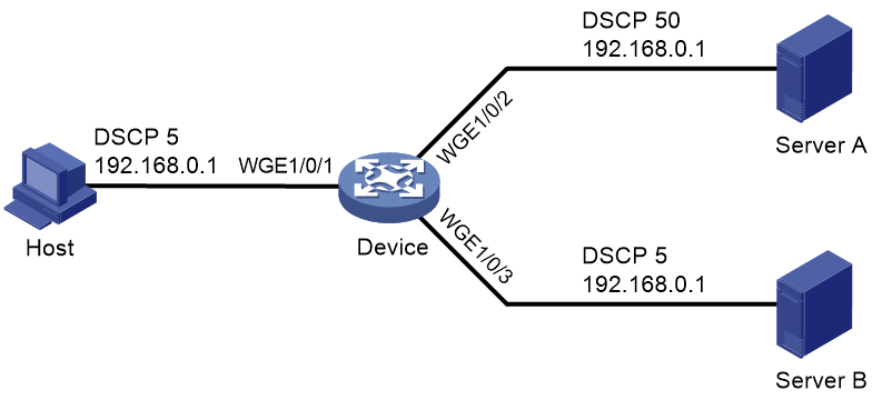
Network configuration
As shown in Figure 3, the source IP address of packets from the host to Server A is 192.168.0.1, and the DSCP field is 5.
Configure multiple QoS policies to meet the following requirements:
· Perform accounting on the packets from the host to Server A.
· Mirror the packets from the host to Server A to Twenty-FiveGigE 1/0/3.
· Mark the packets from the host to Server A with DSCP 50.
· Limit the incoming traffic rate on Twenty-FiveGigE 1/0/1 to 10 Mbps.
Procedure
# Configure ACL 2000 to match the packets with source IP address 192.168.0.1.
<Device> system-view
[Device] acl basic 2000
[Device-acl-ipv4-basic-2000] rule permit source 192.168.0.1 0
[Device-acl-ipv4-basic-2000] quit
# Create a traffic class named host, and use ACL 2000 as the match criterion.
[Device] traffic classifier host
[Device-classifier-host] if-match acl 2000
[Device-classifier-host] quit
# Create a traffic class named any, and configure the traffic class to match all packets.
[Device] traffic classifier any
[Device-classifier-any] if-match any
[Device-classifier-any] quit
# Create a traffic behavior named a, and configure an accounting action.
[Device] traffic behavior a
[Device-behavior-a] accounting packet
[Device-behavior-a] quit
# Create a traffic behavior named m, and configure an action of mirroring traffic to Twenty-FiveGigE 1/0/3.
[Device] traffic behavior m
[Device-behavior-m] mirror-to interface twenty-fivegige 1/0/3
[Device-behavior-m] quit
# Create a traffic behavior named r, and configure an action of marking traffic with DSCP 50.
[Device] traffic behavior r
[Device-behavior-r] remark dscp 50
[Device-behavior-r] quit
# Create a traffic behavior named c, and configure a traffic policing action (CIR 10240 kbps and CBS 102400 bytes).
[Device] traffic behavior c
[Device-behavior-c] car cir 10240 cbs 102400 green pass yellow pass red discard
[Device-behavior-c] quit
# Create an accounting-type QoS policy named policy_a, and associate traffic class host with traffic behavior a in the QoS policy.
[Device] qos accounting policy policy_a
[Device-qospolicy-policy_a] classifier host behavior a
[Device-qospolicy-policy_a] quit
# Create a mirroring-type QoS policy named policy_m, and associate traffic class host with traffic behavior m in the QoS policy.
[Device] qos mirroring policy policy_m
[Device-qospolicy-policy_m] classifier host behavior m
[Device-qospolicy-policy_m] quit
# Create a marking-type QoS policy named policy_r, and associate traffic class host with traffic behavior r in the QoS policy.
[Device] qos remarking policy policy_r
[Device-qospolicy-policy_r] classifier host behavior r
[Device-qospolicy-policy_r] quit
# Create a generic QoS policy named policy_g, and associate traffic class any with traffic behavior c in the QoS policy.
[Device] qos policy policy_g
[Device-qospolicy-policy_g] classifier any behavior c
[Device-qospolicy-policy_g] quit
# Apply the four QoS policies to the inbound direction of Twenty-FiveGigE 1/0/1.
[DeviceA] interface twenty-fivegige 1/0/1
[Device-Twenty-FiveGigE1/0/1] qos apply accounting policy policy_a inbound
[Device-Twenty-FiveGigE1/0/1] qos apply mirroring policy policy_m inbound
[Device-Twenty-FiveGigE1/0/1] qos apply remarking policy policy_r inbound
[Device-Twenty-FiveGigE1/0/1] qos apply policy policy_g inbound
[Device-Twenty-FiveGigE1/0/1] quit
Configuring priority mapping
About priority mapping
When a packet arrives, a device assigns a set of QoS priority parameters to the packet based on either of the following:
· A priority field carried in the packet.
· The port priority of the incoming port.
This process is called priority mapping. During this process, the device can modify the priority of the packet according to the priority mapping rules. The set of QoS priority parameters decides the scheduling priority and forwarding priority of the packet.
Priority mapping is implemented with priority maps and involves the following priorities:
· 802.1p priority.
· DSCP.
· EXP.
· IP precedence.
· Local precedence.
· Drop priority.
About priorities
Priorities include the following types: priorities carried in packets, and priorities locally assigned for scheduling only.
Packet-carried priorities include 802.1p priority, DSCP precedence, IP precedence, and EXP. These priorities have global significance and affect the forwarding priority of packets across the network. For more information about these priorities, see "Appendixes."
Locally assigned priorities only have local significance. They are assigned by the device only for scheduling. These priorities include the local precedence, drop priority, and user priority, as follows:
· Local precedence—Used for queuing. A local precedence value corresponds to an output queue. A packet with higher local precedence is assigned to a higher priority output queue to be preferentially scheduled.
· Drop priority—Used for making packet drop decisions. Packets with the highest drop priority are dropped preferentially.
· User priority—Precedence that the device automatically extracts from a priority field of the packet according to its forwarding path. It is a parameter for determining the scheduling priority and forwarding priority of the packet. The user priority represents the following items:
¡ The 802.1p priority for Layer 2 packets.
¡ The IP precedence for Layer 3 packets.
¡ The EXP for MPLS packets.
The device supports only local precedence and drop priority for scheduling.
Priority maps
The device provides various types of priority maps. By looking through a priority map, the device decides which priority value to assign to a packet for subsequent packet processing.
The default priority maps (as shown in Appendix B Default priority maps) are available for priority mapping. They are adequate in most cases. If a default priority map cannot meet your requirements, you can modify the priority map as required.
Priority mapping configuration methods
You can configure priority mapping by using any of the following methods:
· Configuring priority trust mode—In this method, you can configure a port to look up a trusted priority type (802.1p, for example) in incoming packets in the priority maps. Then, the system maps the trusted priority to the target priority types and values.
· Changing port priority—If no packet priority is trusted, the port priority of the incoming port is used. By changing the port priority of a port, you change the priority of the incoming packets on the port.
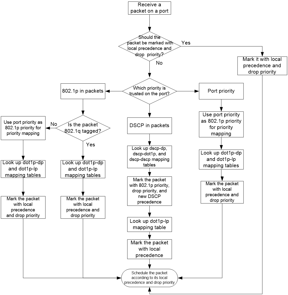
Priority mapping process
On receiving an Ethernet packet on a port, the switch marks the scheduling priorities (local precedence and drop precedence) for the Ethernet packet. This procedure is done according to the priority trust mode of the receiving port and the 802.1Q tagging status of the packet, as shown in Figure 4.
Figure 4 Priority mapping process for an Ethernet packet
The switch marks a received MPLS packet with a scheduling priority based on the priority trust mode and the packet EXP value, as shown in Figure 5.
Figure 5 Priority mapping process for an MPLS packet
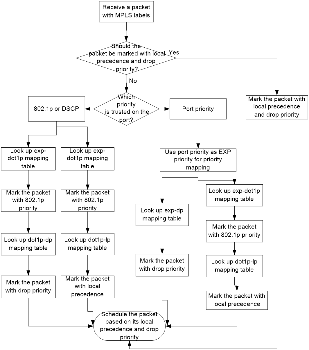
For information about priority marking, see "Configuring priority marking."
Priority mapping tasks at a glance
To configure priority mapping, perform the following tasks:
1. (Optional.) Configuring a priority map
2. Configure a priority mapping method:
¡ Configuring a port to trust packet priority for priority mapping
¡ Changing the port priority of an interface
Configuring a priority map
system-view
2. Enter priority map view.
qos map-table { dot1p-dp | dot1p-exp | dot1p-lp | dscp-dot1p | dscp-dp | dscp-dscp | exp-dot1p }
3. Configure mappings for the priority map.
import import-value-list export export-value
By default, the default priority maps are used. For more information, see "Appendix B Default priority maps."
If you execute this command multiple times, the most recent configuration takes effect.
Configuring a port to trust packet priority for priority mapping
About this task
You can configure the device to trust a particular priority field carried in packets for priority mapping on ports or globally. When you configure the trusted packet priority type on an interface, use the following available keywords:
· dot1p—Uses the 802.1p priority of received packets for mapping.
· dscp—Uses the DSCP precedence of received IP packets for mapping.
Restrictions and guidelines
In a VXLAN or EVPN network, if the access mode of an AC is VLAN or the packets forwarded by the output interface of a VXLAN tunnel do not carry VLAN tags, the device cannot use the 802.1p priority of packets for priority mapping.
For a VXLAN tunnel interface to trust the DSCP priority in the outer IP header of VXLAN packets, you must configure both of the following commands:
· qos trust tunnel-dscp (in system view).
· qos trust dscp (in interface view for the physical interface of the VXLAN tunnel interface).
For a VXLAN tunnel interface to trust the 802.1p priority in the outer Ethernet header of VXLAN packets, you must configure both of the following commands:
· qos trust tunnel-dot1p (in system view).
· qos trust dot1p (in interface view for the physical interface of the VXLAN tunnel interface).
For PFC to take effect on an overlay network, configure the qos trust tunnel-dot1p command on all VTEPs. For information about overlay networks, see VXLAN Configuration Guide. For information about PFC, see Ethernet interface configuration in Layer 2—LAN Switching Configuration Guide.
The term "interface" in this section collectively refers to Layer 2 and Layer 3 Ethernet interfaces. You can use the port link-mode command to configure an Ethernet port as a Layer 2 or Layer 3 interface (see Layer 2—LAN Switching Configuration Guide).
Procedure
1. Enter system view.
system-view
2. Enter interface view.
interface interface-type interface-number
3. Configure the trusted packet priority type.
qos trust { dot1p | dscp }
By default, an interface does not trust any packet priority and uses the port priority as the 802.1p priority for mapping.
4. Return to system view.
quit
5. (Optional.) Configure the global priority trust mode for VXLAN packets.
qos trust { tunnel-dot1p | tunnel-dscp }
By default, the global priority trust mode for VXLAN packets is not configured.
Changing the port priority of an interface
About this task
If an interface does not trust any packet priority, the device uses its port priority to look for priority parameters for the incoming packets. By changing port priority, you can prioritize traffic received on different interfaces.
Procedure
1. Enter system view.
system-view
2. Enter interface view.
interface interface-type interface-number
3. Set the port priority of the interface.
qos priority [ dscp ] priority-value
The default setting is 0.
Display and maintenance commands for priority mapping
Execute display commands in any view.
|
Task |
Command |
|
Display priority map configuration. |
display qos map-table [ dot1p-dp | dot1p-exp | dot1p-lp | dscp-dot1p | dscp-dp | dscp-dscp | exp-dot1p ] |
|
Display the trusted packet priority type on a port. |
display qos trust interface [ interface-type interface-number ] |
Priority mapping configuration examples
Example: Configuring a priority trust mode
Network configuration
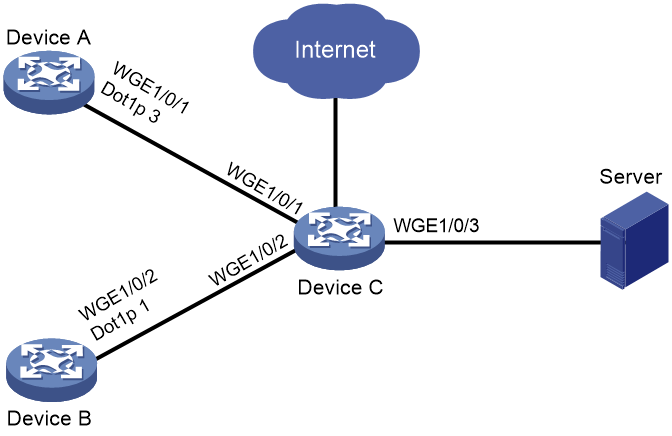
As shown in Figure 6:
· The 802.1p priority of traffic from Device A to Device C is 3.
· The 802.1p priority of traffic from Device B to Device C is 1.
Configure Device C to preferentially process packets from Device A to the server when Twenty-FiveGigE 1/0/3 of Device C is congested.
Procedure
(Method 1) Configure Device C to trust packet priority
# Configure Twenty-FiveGigE 1/0/1 and Twenty-FiveGigE 1/0/2 to trust the 802.1p priority for priority mapping.
<DeviceC> system-view
[DeviceC] interface twenty-fivegige 1/0/1
[DeviceC-Twenty-FiveGigE1/0/1] qos trust dot1p
[DeviceC-Twenty-FiveGigE1/0/1] quit
[DeviceC] interface twenty-fivegige 1/0/2
[DeviceC-Twenty-FiveGigE1/0/2] qos trust dot1p
[DeviceC-Twenty-FiveGigE1/0/2] quit
(Method 2) Configure Device C to trust port priority
# Assign port priority to Twenty-FiveGigE 1/0/1 and Twenty-FiveGigE 1/0/2. Make sure the following requirements are met:
· The priority of Twenty-FiveGigE 1/0/1 is higher than that of Twenty-FiveGigE 1/0/2.
· No trusted packet priority type is configured on Twenty-FiveGigE 1/0/1 or Twenty-FiveGigE 1/0/2.
<DeviceC> system-view
[DeviceC] interface twenty-fivegige 1/0/1
[DeviceC-Twenty-FiveGigE1/0/1] qos priority 3
[DeviceC-Twenty-FiveGigE1/0/1] quit
[DeviceC] interface twenty-fivegige 1/0/2
[DeviceC-Twenty-FiveGigE1/0/2] qos priority 1
[DeviceC-Twenty-FiveGigE1/0/2] quit
Example: Configuring priority mapping tables and priority marking
Network configuration
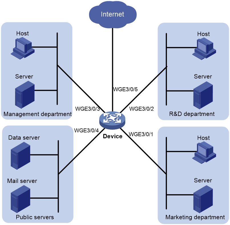
As shown in Figure 7:
· The Marketing department connects to Twenty-FiveGigE 1/0/1 of Device, which sets the 802.1p priority of traffic from the Marketing department to 3.
· The R&D department connects to Twenty-FiveGigE 1/0/2 of Device, which sets the 802.1p priority of traffic from the R&D department to 4.
· The Management department connects to Twenty-FiveGigE 1/0/3 of Device, which sets the 802.1p priority of traffic from the Management department to 5.
Configure port priority, 802.1p-to-local mapping table, and priority marking to implement the plan as described in Table 1.
|
Traffic destination |
Traffic priority order |
Queuing plan |
||
|
Traffic source |
Output queue |
Queue priority |
||
|
Public servers |
R&D department > Management department > Marketing department |
R&D department |
6 |
High |
|
Management department |
4 |
Medium |
||
|
Marketing department |
2 |
Low |
||
|
Internet |
Management department > Marketing department > R&D department |
R&D department |
2 |
Low |
|
Management department |
6 |
High |
||
|
Marketing department |
4 |
Medium |
||
Procedure
1. Configure trusting port priority:
# Set the port priority of Twenty-FiveGigE 1/0/1 to 3.
<Device> system-view
[Device] interface twenty-fivegige 1/0/1
[Device-Twenty-FiveGigE1/0/1] qos priority 3
[Device-Twenty-FiveGigE1/0/1] quit
# Set the port priority of Twenty-FiveGigE 1/0/2 to 4.
[Device] interface twenty-fivegige 1/0/2
[Device-Twenty-FiveGigE1/0/2] qos priority 4
[Device-Twenty-FiveGigE1/0/2] quit
# Set the port priority of Twenty-FiveGigE 1/0/3 to 5.
[Device] interface twenty-fivegige 1/0/3
[Device-Twenty-FiveGigE1/0/3] qos priority 5
[Device-Twenty-FiveGigE1/0/3] quit
2. Configure the 802.1p-to-local mapping table to map 802.1p priority values 3, 4, and 5 to local precedence values 2, 6, and 4.
This guarantees the R&D department, Management department, and Marketing department decreased priorities to access the public servers.
[Device] qos map-table dot1p-lp
[Device-maptbl-dot1p-lp] import 3 export 2
[Device-maptbl-dot1p-lp] import 4 export 6
[Device-maptbl-dot1p-lp] import 5 export 4
[Device-maptbl-dot1p-lp] quit
3. Configure priority marking to mark the packets from Management department, Marketing department, and R&D department to the Internet with 802.1p priority values 4, 5, and 3.
This guarantees the Management department, Marketing department, and R&D department decreased priorities to access the Internet.
# Create ACL 3000, and configure a rule to match HTTP packets.
[Device] acl advanced 3000
[Device-acl-adv-3000] rule permit tcp destination-port eq 80
[Device-acl-adv-3000] quit
# Create a traffic class named http, and use ACL 3000 as a match criterion.
[Device] traffic classifier http
[Device-classifier-http] if-match acl 3000
[Device-classifier-http] quit
# Create a traffic behavior named admin, and configure a marking action for the Management department.
[Device] traffic behavior admin
[Device-behavior-admin] remark dot1p 4
[Device-behavior-admin] quit
# Create a QoS policy named admin, and associate traffic class http with traffic behavior admin in QoS policy admin.
[Device] qos policy admin
[Device-qospolicy-admin] classifier http behavior admin
[Device-qospolicy-admin] quit
# Apply QoS policy admin to the inbound direction of Twenty-FiveGigE 1/0/3.
[Device] interface twenty-fivegige 1/0/3
[Device-Twenty-FiveGigE1/0/3] qos apply policy admin inbound
# Create a traffic behavior named market, and configure a marking action for the Marketing department.
[Device] traffic behavior market
[Device-behavior-market] remark dot1p 5
[Device-behavior-market] quit
# Create a QoS policy named market, and associate traffic class http with traffic behavior market in QoS policy market.
[Device] qos policy market
[Device-qospolicy-market] classifier http behavior market
[Device-qospolicy-market] quit
# Apply QoS policy market to the inbound direction of Twenty-FiveGigE 1/0/1.
[Device] interface twenty-fivegige 1/0/1
[Device-Twenty-FiveGigE1/0/1] qos apply policy market inbound
# Create a traffic behavior named rd, and configure a marking action for the R&D department.
[Device] traffic behavior rd
[Device-behavior-rd] remark dot1p 3
[Device-behavior-rd] quit
# Create a QoS policy named rd, and associate traffic class http with traffic behavior rd in QoS policy rd.
[Device] qos policy rd
[Device-qospolicy-rd] classifier http behavior rd
[Device-qospolicy-rd] quit
# Apply QoS policy rd to the inbound direction of Twenty-FiveGigE 1/0/2.
[Device] interface twenty-fivegige 1/0/2
[Device-Twenty-FiveGigE1/0/2] qos apply policy rd inbound
Configuring traffic policing, GTS, and rate limit
About traffic policing, GTS, and rate limit
Traffic limit helps assign network resources (including bandwidth) and increase network performance. For example, you can configure a flow to use only the resources committed to it in a certain time range. This avoids network congestion caused by burst traffic.
Traffic policing, Generic Traffic Shaping (GTS), and rate limit control the traffic rate and resource usage according to traffic specifications. You can use token buckets for evaluating traffic specifications.
Traffic evaluation and token buckets
Token bucket features
A token bucket is analogous to a container that holds a certain number of tokens. Each token represents a certain forwarding capacity. The system puts tokens into the bucket at a constant rate. When the token bucket is full, the extra tokens cause the token bucket to overflow.
Evaluating traffic with the token bucket
A token bucket mechanism evaluates traffic by looking at the number of tokens in the bucket. If the number of tokens in the bucket is enough for forwarding the packets:
· The traffic conforms to the specification (called conforming traffic).
· The corresponding tokens are taken away from the bucket.
Otherwise, the traffic does not conform to the specification (called excess traffic).
A token bucket has the following configurable parameters:
· Mean rate at which tokens are put into the bucket, which is the permitted average rate of traffic. It is usually set to the committed information rate (CIR).
· Burst size or the capacity of the token bucket. It is the maximum traffic size permitted in each burst. It is usually set to the committed burst size (CBS). The set burst size must be greater than the maximum packet size.
Each arriving packet is evaluated.
Complicated evaluation
You can set two token buckets, bucket C and bucket E, to evaluate traffic in a more complicated environment and achieve more policing flexibility. The following are main mechanisms used for complicated evaluation:
· Single rate two color—Uses one token bucket and the following parameters:
¡ CIR—Rate at which tokens are put into bucket C. It sets the average packet transmission or forwarding rate allowed by bucket C.
¡ CBS—Size of bucket C, which specifies the transient burst of traffic that bucket C can forward.
When a packet arrives, the following rules apply:
¡ If bucket C has enough tokens to forward the packet, the packet is colored green.
¡ Otherwise, the packet is colored red.
· Single rate three color—Uses two token buckets and the following parameters:
¡ CIR—Rate at which tokens are put into bucket C. It sets the average packet transmission or forwarding rate allowed by bucket C.
¡ CBS—Size of bucket C, which specifies the transient burst of traffic that bucket C can forward.
¡ EBS—Size of bucket E minus size of bucket C, which specifies the transient burst of traffic that bucket E can forward. The EBS cannot be 0. The size of E bucket is the sum of the CBS and EBS.
When a packet arrives, the following rules apply:
¡ If bucket C has enough tokens, the packet is colored green.
¡ If bucket C does not have enough tokens but bucket E has enough tokens, the packet is colored yellow.
¡ If neither bucket C nor bucket E has sufficient tokens, the packet is colored red.
· Two rate three color—Uses two token buckets and the following parameters:
¡ CIR—Rate at which tokens are put into bucket C. It sets the average packet transmission or forwarding rate allowed by bucket C.
¡ CBS—Size of bucket C, which specifies the transient burst of traffic that bucket C can forward.
¡ PIR—Rate at which tokens are put into bucket E, which specifies the average packet transmission or forwarding rate allowed by bucket E.
¡ EBS—Size of bucket E, which specifies the transient burst of traffic that bucket E can forward.
When a packet arrives, the following rules apply:
¡ If bucket C has enough tokens, the packet is colored green.
¡ If bucket C does not have enough tokens but bucket E has enough tokens, the packet is colored yellow.
¡ If neither bucket C nor bucket E has sufficient tokens, the packet is colored red.
Traffic policing
Traffic policing supports policing the inbound traffic and the outbound traffic.
A typical application of traffic policing is to supervise the specification of traffic entering a network and limit it within a reasonable range. Another application is to "discipline" the extra traffic to prevent aggressive use of network resources by an application. For example, you can limit bandwidth for HTTP packets to less than 50% of the total. If the traffic of a session exceeds the limit, traffic policing can drop the packets or reset the IP precedence of the packets. Figure 8 shows an example of policing outbound traffic on an interface.
Traffic policing is widely used in policing traffic entering the ISP networks. It can classify the policed traffic and take predefined policing actions on each packet depending on the evaluation result:
· Forwarding the packet if the evaluation result is "conforming."
· Dropping the packet if the evaluation result is "excess."
· Forwarding the packet with its precedence re-marked if the evaluation result is "conforming."
· Delivering the packet to next-level traffic policing with its precedence re-marked if the evaluation result is "conforming."
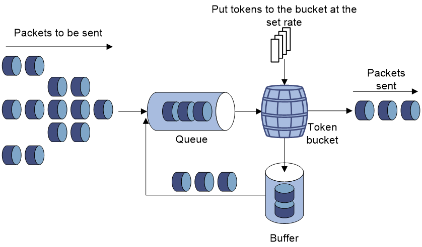
GTS
GTS supports shaping the outbound traffic. GTS limits the outbound traffic rate by buffering exceeding traffic. You can use GTS to adapt the traffic output rate on a device to the input traffic rate of its connected device to avoid packet loss.
The differences between traffic policing and GTS are as follows:
· Packets to be dropped with traffic policing are retained in a buffer or queue with GTS, as shown in Figure 9. When enough tokens are in the token bucket, the buffered packets are sent at an even rate.
· GTS can result in additional delay and traffic policing does not.
For example, in Figure 10, Device B performs traffic policing on packets from Device A and drops packets exceeding the limit. To avoid packet loss, you can perform GTS on the outgoing interface of Device A so that packets exceeding the limit are cached in Device A. Once resources are released, GTS takes out the cached packets and sends them out.

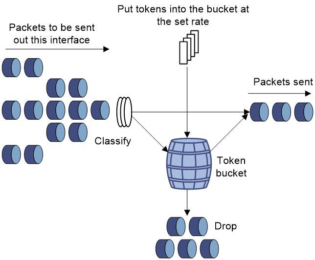
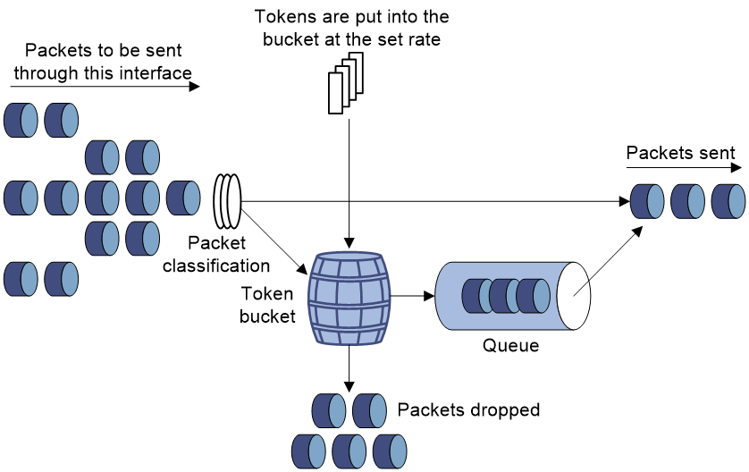
Rate limit
Rate limit controls the rate of inbound and outbound traffic. The outbound traffic is taken for example.
The rate limit of an interface specifies the maximum rate for forwarding packets (excluding critical packets).
Rate limit also uses token buckets for traffic control. When rate limit is configured on an interface, a token bucket handles all packets to be sent through the interface for rate limiting. If enough tokens are in the token bucket, packets can be forwarded. Otherwise, packets are put into QoS queues for congestion management. In this way, the traffic passing the interface is controlled.
Figure 11 Rate limit implementation
The token bucket mechanism limits traffic rate when accommodating bursts. It allows bursty traffic to be transmitted if enough tokens are available. If tokens are scarce, packets cannot be transmitted until efficient tokens are generated in the token bucket. It restricts the traffic rate to the rate for generating tokens.
Rate limit controls the total rate of all packets on an interface. It is easier to use than traffic policing in controlling the total traffic rate.
Restrictions and guidelines: Traffic policing, GTS, and rate limit configuration
The specified CIR does not take traffic transmitted in interframe gaps into account, and the actually allowed rate on an interface is greater than the specified CIR.
An interframe gap is a time interval for transmitting 12 bits between frames. This gap serves the following roles:
· Allows the device to differentiate one frame from another.
· Allows for time for the device to process the current frame and to prepare for receiving the next frame.
Configuring traffic policing
Restrictions and guidelines
If you both configure traffic policing by using the MQC approach and apply a queue scheduling profile on an interface, the device performs queue scheduling before traffic policing. In other words, the red packets to be dropped by traffic policing will also be processed by the queue scheduling profile.
To police the outgoing traffic on a Layer 3 aggregate interface, apply a QoS policy containing a traffic policing action to the outbound direction of each member port of the aggregate interface in sharing mode. For example, to police the outgoing traffic on a Layer 3 aggregate interface to 1000 kbps, apply the QoS policy to the outbound direction of each member port of the aggregate interface in sharing mode.
To police the outgoing traffic on a Layer 3 aggregate subinterface, configure an SVLAN match criterion and apply the QoS policy to the outbound direction of each member port of the aggregate interface in sharing mode. For example, if you execute the if-match service-vlan 20 command in a traffic class, the outgoing traffic on Layer 3 aggregate subinterface 20 is policed to the specified CIR.
Procedure
1. Enter system view.
system-view
2. Define a traffic class.
a. Create a traffic class and enter traffic class view.
traffic classifier classifier-name [ operator { and | or } ]
b. Configure a match criterion.
if-match match-criteria
By default, no match criterion is configured.
For more information about the if-match command, see ACL and QoS Command Reference.
c. Return to system view.
quit
3. Define a traffic behavior.
a. Create a traffic behavior and enter traffic behavior view.
traffic behavior behavior-name
b. Configure a traffic policing action.
car cir [ pps ] committed-information-rate [ cbs committed-burst-size [ ebs excess-burst-size ] ] [ green action | red action | yellow action ] *
car cir [ pps ] committed-information-rate [ cbs committed-burst-size ] pir [ pps ] peak-information-rate [ ebs excess-burst-size ] [ green action | red action | yellow action ] *
By default, no traffic policing action is configured.
c. Return to system view.
quit
4. Define a QoS policy.
a. Create a QoS policy and enter QoS policy view.
qos policy policy-name
b. Associate the traffic class with the traffic behavior in the QoS policy.
classifier classifier-name behavior behavior-name
By default, a traffic class is not associated with a traffic behavior.
c. Return to system view.
quit
5. Apply the QoS policy.
For more information, see "Applying the QoS policy."
By default, no QoS policy is applied.
Configuring GTS
Restrictions and guidelines
The term "interface" in this section collectively refers to Layer 2 and Layer 3 Ethernet interfaces. You can use the port link-mode command to configure an Ethernet port as a Layer 2 or Layer 3 interface (see Layer 2—LAN Switching Configuration Guide).
Procedure
1. Enter system view.
system-view
2. Enter interface view.
interface interface-type interface-number
3. Configure GTS for a queue.
qos gts queue queue-id cir committed-information-rate [ cbs committed-burst-size ]
By default, GTS is not configured on an interface.
Configuring the rate limit
Restrictions and guidelines
The term "interface" in this section collectively refers to Layer 2 and Layer 3 Ethernet interfaces. You can use the port link-mode command to configure an Ethernet port as a Layer 2 or Layer 3 interface (see Layer 2—LAN Switching Configuration Guide).
Procedure
1. Enter system view.
system-view
2. Enter interface view.
interface interface-type interface-number
3. Configure the rate limit for the interface.
qos lr outbound cir committed-information-rate [ cbs committed-burst-size ]
By default, no rate limit is configured on an interface.
Display and maintenance commands for traffic policing, GTS, and rate limit
Execute display commands in any view.
|
Task |
Command |
|
Display GTS configuration and statistics for interfaces. |
display qos gts interface [ interface-type interface-number ] |
|
Display rate limit configuration and statistics. |
display qos lr interface [ interface-type interface-number ] |
|
Display QoS and ACL resource usage. |
display qos-acl resource [ slot slot-number ] |
|
Display traffic behavior configuration. |
display traffic behavior user-defined [ behavior-name ] |
Traffic policing, GTS, and rate limit configuration examples
Example: Configuring traffic policing and GTS
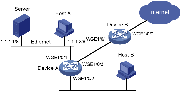
Network requirements
As shown in Figure 12:
· The server, Host A, and Host B can access the Internet through Device A and Device B.
· The server, Host A, and Twenty-FiveGigE 1/0/1 of Device A are in the same network segment.
· Host B and Twenty-FiveGigE 1/0/2 of Device A are in the same network segment.
Perform traffic control for the packets that Twenty-FiveGigE 1/0/1 of Device A receives from the server and Host A using the following guidelines:
· Limit the rate of packets from the server to 10240 kbps. When the traffic rate is below 10240 kbps, the traffic is forwarded. When the traffic rate exceeds 10240 kbps, the excess packets are marked with DSCP value 0 and then forwarded.
· Limit the rate of packets from Host A to 2560 kbps. When the traffic rate is below 2560 kbps, the traffic is forwarded. When the traffic rate exceeds 2560 kbps, the excess packets are dropped.
Perform traffic control on Twenty-FiveGigE 1/0/1 and Twenty-FiveGigE 1/0/2 of Device B using the following guidelines:
· Limit the incoming traffic rate on Twenty-FiveGigE 1/0/1 to 20480 kbps, and the excess packets are dropped.
· Limit the outgoing traffic rate on Twenty-FiveGigE 1/0/2 to 10240 kbps, and the excess packets are dropped.
Configuration procedure
1. Configure Device A:
# Configure ACL 2001 and ACL 2002 to permit the packets from the server and Host A, respectively.
[DeviceA] acl basic 2001
[DeviceA-acl-ipv4-basic-2001] rule permit source 1.1.1.1 0
[DeviceA-acl-ipv4-basic-2001] quit
[DeviceA] acl basic 2002
[DeviceA-acl-ipv4-basic-2002] rule permit source 1.1.1.2 0
[DeviceA-acl-ipv4-basic-2002] quit
# Create a traffic class named server, and use ACL 2001 as the match criterion.
[DeviceA] traffic classifier server
[DeviceA-classifier-server] if-match acl 2001
[DeviceA-classifier-server] quit
# Create a traffic class named host, and use ACL 2002 as the match criterion.
[DeviceA] traffic classifier host
[DeviceA-classifier-host] if-match acl 2002
[DeviceA-classifier-host] quit
# Create a traffic behavior named server, and configure a traffic policing action (CIR 10240 kbps).
[DeviceA] traffic behavior server
[DeviceA-behavior-server] car cir 10240 red remark-dscp-pass 0
[DeviceA-behavior-server] quit
# Create a traffic behavior named host, and configure a traffic policing action (CIR 2560 kbps).
[DeviceA] traffic behavior host
[DeviceA-behavior-host] car cir 2560
[DeviceA-behavior-host] quit
# Create a QoS policy named car, and associate traffic classes server and host with traffic behaviors server and host in QoS policy car, respectively.
[DeviceA] qos policy car
[DeviceA-qospolicy-car] classifier server behavior server
[DeviceA-qospolicy-car] classifier host behavior host
[DeviceA-qospolicy-car] quit
# Apply QoS policy car to the inbound direction of Twenty-FiveGigE 1/0/1.
[DeviceA] interface twenty-fivegige 1/0/1
[DeviceA-Twenty-FiveGigE1/0/1] qos apply policy car inbound
2. Configure Device B:
# Create ACL 3001, and configure a rule to match HTTP packets.
<DeviceB> system-view
[DeviceB] acl advanced 3001
[DeviceB-acl-adv-3001] rule permit tcp destination-port eq 80
[DeviceB-acl-adv-3001] quit
# Create a traffic class named http, and use ACL 3001 as a match criterion.
[DeviceB] traffic classifier http
[DeviceB-classifier-http] if-match acl 3001
[DeviceB-classifier-http] quit
# Create a traffic class named class, and configure the traffic class to match all packets.
[DeviceB] traffic classifier class
[DeviceB-classifier-class] if-match any
[DeviceB-classifier-class] quit
# Create a traffic behavior named car_inbound, and configure a traffic policing action (CIR 20480 kbps).
[DeviceB] traffic behavior car_inbound
[DeviceB-behavior-car_inbound] car cir 20480
[DeviceB-behavior-car_inbound] quit
# Create a traffic behavior named car_outbound, and configure a traffic policing action (CIR 10240 kbps).
[DeviceB] traffic behavior car_outbound
[DeviceB-behavior-car_outbound] car cir 10240
[DeviceB-behavior-car_outbound] quit
# Create a QoS policy named car_inbound, and associate traffic class class with traffic behavior car_inbound in QoS policy car_inbound.
[DeviceB] qos policy car_inbound
[DeviceB-qospolicy-car_inbound] classifier class behavior car_inbound
[DeviceB-qospolicy-car_inbound] quit
# Create a QoS policy named car_outbound, and associate traffic class http with traffic behavior car_outbound in QoS policy car_outbound.
[DeviceB] qos policy car_outbound
[DeviceB-qospolicy-car_outbound] classifier http behavior car_outbound
[DeviceB-qospolicy-car_outbound] quit
# Apply QoS policy car_inbound to the inbound direction of Twenty-FiveGigE 1/0/1.
[DeviceB] interface twenty-fivegige 1/0/1
[DeviceB-Twenty-FiveGigE1/0/1] qos apply policy car_inbound inbound
# Apply QoS policy car_outbound to the outbound direction of Twenty-FiveGigE 1/0/2.
[DeviceB] interface twenty-fivegige 1/0/2
[DeviceB-Twenty-FiveGigE1/0/2] qos apply policy car_outbound outbound
Configuring congestion management
About congestion management
Cause, negative results, and countermeasure of congestion
Congestion occurs on a link or node when traffic size exceeds the processing capability of the link or node. It is typical of a statistical multiplexing network and can be caused by link failures, insufficient resources, and various other causes.
Figure 13 shows two typical congestion scenarios.
Figure 13 Traffic congestion scenarios

Congestion produces the following negative results:
· Increased delay and jitter during packet transmission.
· Decreased network throughput and resource use efficiency.
· Network resource (memory, in particular) exhaustion and even system breakdown.
Congestion is unavoidable in switched networks and multiuser application environments. To improve the service performance of your network, take measures to manage and control it.
The key to congestion management is defining a resource dispatching policy to prioritize packets for forwarding when congestion occurs.
Congestion management methods
Congestion management uses queuing and scheduling algorithms to classify and sort traffic leaving a port.
The device supports the following queuing mechanisms:
· SP.
· WRR.
· WFQ.
SP queuing
SP queuing is designed for mission-critical applications that require preferential service to reduce the response delay when congestion occurs.
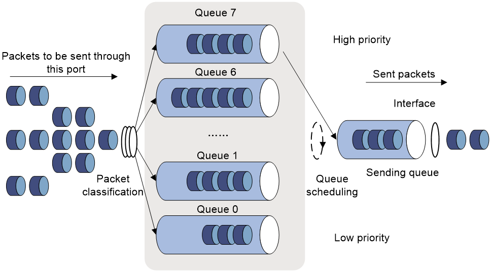
In Figure 14, SP queuing classifies eight queues on a port into eight classes, numbered 7 to 0 in descending priority order.
SP queuing schedules the eight queues in the descending order of priority. SP queuing sends packets in the queue with the highest priority first. When the queue with the highest priority is empty, it sends packets in the queue with the second highest priority, and so on. You can assign mission-critical packets to a high priority queue to make sure they are always served first. Common service packets can be assigned to low priority queues to be transmitted when high priority queues are empty.
The disadvantage of SP queuing is that packets in the lower priority queues cannot be transmitted if packets exist in the higher priority queues. In the worst case, lower priority traffic might never get serviced.
WRR queuing
WRR queuing schedules all the queues in turn to ensure that every queue is served for a certain time, as shown in Figure 15.
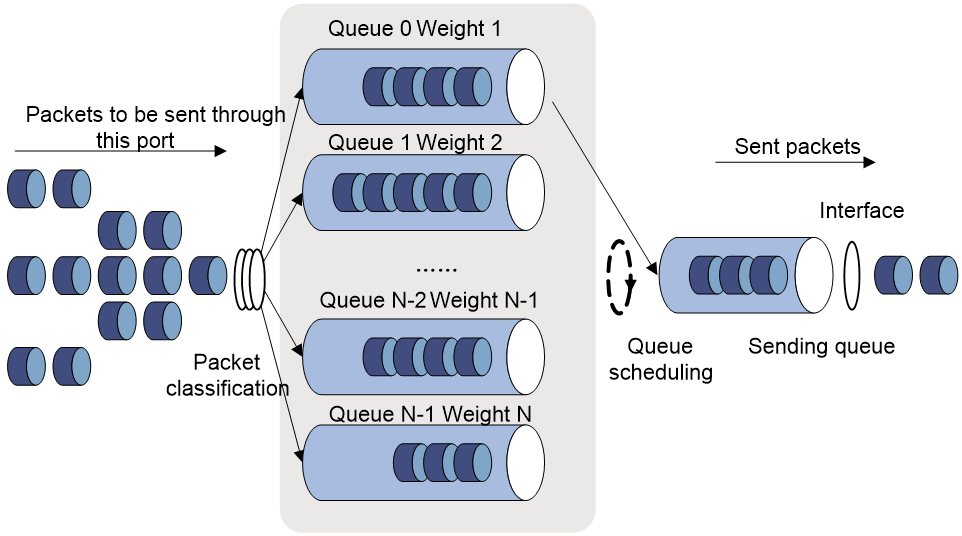
Assume a port provides eight output queues. WRR assigns each queue a weight value (represented by w7, w6, w5, w4, w3, w2, w1, or w0). The weight value of a queue decides the proportion of resources assigned to the queue. On a 100 Mbps port, you can set the weight values to 50, 30, 10, 10, 50, 30, 10, and 10 for w7 through w0. In this way, the queue with the lowest priority can get a minimum of 5 Mbps of bandwidth. WRR solves the problem that SP queuing might fail to serve packets in low-priority queues for a long time.
Another advantage of WRR queuing is that when the queues are scheduled in turn, the service time for each queue is not fixed. If a queue is empty, the next queue will be scheduled immediately. This improves bandwidth resource use efficiency.
WRR queuing includes the following types:
· Basic WRR queuing—Contains multiple queues. You can set the weight for each queue, and WRR schedules these queues based on the user-defined parameters in a round robin manner.
· Group-based WRR queuing—All the queues are scheduled by WRR. You can divide output queues to WRR priority queue group 1 and WRR priority queue group 2. Round robin queue scheduling is performed for group 1 first. If group 1 is empty, round robin queue scheduling is performed for group 2. Only WRR priority queue group 1 is supported in the current software version.
On an interface enabled with group-based WRR queuing, you can assign queues to the SP group. Queues in the SP group are scheduled with SP. The SP group has higher scheduling priority than the WRR groups.
WFQ queuing
Figure 16 WFQ queuing

WFQ is similar to WRR. WFQ queuing includes basic WFQ queuing and group-based WFQ queuing. Only WFQ group 1 is supported in the current software version.
On an interface with group-based WFQ queuing enabled, you can also assign queues to the SP group. The difference is that WFQ enables you to set guaranteed bandwidth that a WFQ queue can get during congestion.
SP+WFQ queuing schedules traffic in the following order:
1. Schedules the traffic conforming to the minimum guaranteed bandwidth of each queue in the WFQ group.
2. Schedules the queues in the SP group based on their priorities.
3. Schedules the traffic in each queue in the WFQ group according to the configured weights when all queues in the SP group are empty.
Congestion management tasks at a glance
To configure congestion management, perform the following tasks:
· Configuring queuing on an interface
¡ Configuring SP queuing
¡ Configuring WRR queuing
¡ Configuring WFQ queuing
· Configuring a queue scheduling profile
Configuring queuing on an interface
Restrictions and guidelines for queuing configuration
The term "interface" in this section collectively refers to Layer 2 and Layer 3 Ethernet interfaces. You can use the port link-mode command to configure an Ethernet port as a Layer 2 or Layer 3 interface (see Layer 2—LAN Switching Configuration Guide).
Configuring SP queuing
1. Enter system view.
system-view
2. Enter interface view.
interface interface-type interface-number
3. Configure SP queuing.
qos sp
By default, an interface uses byte-count WRR queuing.
Configuring WRR queuing
1. Enter system view.
system-view
2. Enter interface view.
interface interface-type interface-number
3. Enable WRR queuing.
qos wrr { byte-count | weight }
By default, an interface uses byte-count WRR queuing.
4. Assign a queue to a WRR group, and configure scheduling parameters for the queue.
qos wrr queue-id group 1 { byte-count | weight } schedule-value
By default, all queues on a WRR-enabled interface are in WRR group 1, and queues 0 through 7 have a weight of 1, 2, 3, 4, 5, 9, 13, and 15, respectively.
Configuring WFQ queuing
1. Enter system view.
system-view
2. Enter interface view.
interface interface-type interface-number
3. Enable WFQ queuing.
qos wfq { byte-count | weight }
By default, an interface uses byte-count WRR queuing.
4. Assign a queue to a WFQ group, and configure scheduling parameters for the queue.
qos wfq queue-id group 1 { byte-count | weight } schedule-value
By default, all queues on a WFQ-enabled interface are in WFQ group 1 and have a weight of 1.
Configuring SP+WRR queuing
Restrictions and guidelines
Procedure
1. Enter system view.
system-view
2. Enter interface view.
interface interface-type interface-number
3. Enable byte-count or packet-count WRR queuing.
qos wrr { byte-count | weight }
By default, an interface uses byte-count WRR queuing.
4. Assign a queue to the SP group.
qos wrr queue-id group sp
By default, all queues on a WRR-enabled interface are in WRR group 1.
5. Assign a queue to a WRR group, and configure a scheduling weight for the queue.
qos wrr queue-id group 1 { byte-count | weight } schedule-value
By default, all queues on a WRR-enabled interface are in WRR group 1, and queues 0 through 7 have a weight of 1, 2, 3, 4, 5, 9, 13, and 15, respectively.
Configuring SP+WFQ queuing
Restrictions and guidelines
To configure the scheduling weight, you must specify the same scheduling unit as specified when enabling WFQ queuing.
Procedure
1. Enter system view.
system-view
2. Enter interface view.
interface interface-type interface-number
3. Enable byte-count or packet-count WFQ queuing.
qos wfq [ byte-count | weight ]
By default, an interface uses byte-count WRR queuing.
4. Assign a queue to the SP group.
qos wfq queue-id group sp
By default, all queues on a WFQ-enabled interface are in WFQ group 1.
5. Assign a queue to a WFQ queue scheduling group, and configure a scheduling weight for the queue.
qos wfq queue-id group 1 { byte-count | weight } schedule-value
By default, all queues on a WFQ-enabled interface are in WFQ group 1 and have a weight of 1.
6. (Optional.) Set the minimum guaranteed bandwidth for a queue.
qos bandwidth queue queue-id min bandwidth-value
The default setting is 64 kbps.
Configuring a queue scheduling profile
About queue scheduling profiles
In a queue scheduling profile, you can configure scheduling parameters for each queue. By applying the queue scheduling profile to an interface, you can implement congestion management on the interface.
Queue scheduling profiles support three queue scheduling algorithms: SP, WRR, and WFQ. In a queue scheduling profile, you can configure SP + WRR or SP + WFQ. For information about each scheduling algorithm, see "About congestion management." When SP and WRR groups are configured in a queue scheduling profile, Figure 17 shows the scheduling order.
Figure 17 Queue scheduling profile configured with both SP and WRR
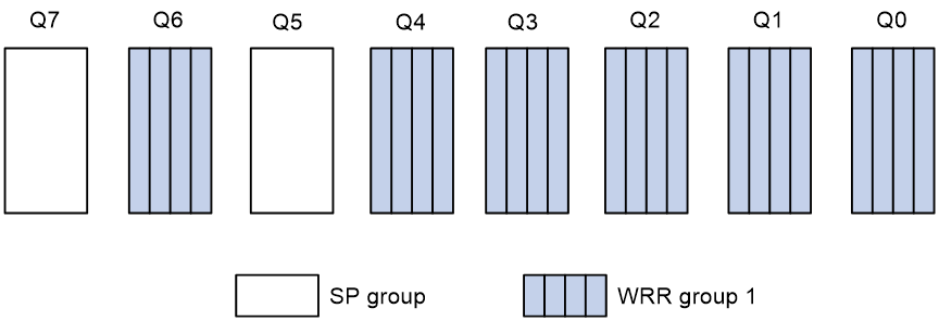
· Queue 7 has the highest priority in the SP group. Its packets are sent preferentially.
· Queue 5 has the second highest priority in the SP group. Packets in queue 5 are sent when queue 7 is empty.
· All queues in WRR group 1 are scheduled according to their weights. When queue 7 and queue 5 are empty, WRR group 1 is scheduled.
Restrictions and guidelines for queue scheduling profile configuration
When you configure a queue scheduling profile, follow these restrictions and guidelines:
· The term "interface" in this section collectively refers to Layer 2 and Layer 3 Ethernet interfaces. You can use the port link-mode command to configure an Ethernet port as a Layer 2 or Layer 3 interface (see Layer 2—LAN Switching Configuration Guide).
· Only one queue scheduling profile can be applied to an interface.
· You can modify the scheduling parameters in a queue scheduling profile already applied to an interface.
· If you both configure traffic policing by using the MQC approach and apply a queue scheduling profile on an interface, the device performs queue scheduling before traffic policing. In other words, the red packets to be dropped by traffic policing will also be processed by the queue scheduling profile.
Configuring a queue scheduling profile
1. Enter system view.
system-view
2. Create a queue scheduling profile and enter queue scheduling profile view.
qos qmprofile profile-name
3. (Optional.) Configure queue scheduling parameters.
¡ Configure a queue to use SP.
queue queue-id sp
¡ Configure a queue to use WRR.
queue queue-id wrr group group-id { weight | byte-count } schedule-value
¡ Configure a queue to use WFQ.
queue queue-id wfq { weight | byte-count } schedule-value
By default, all queues in a queue scheduling profile use packet-count WRR queuing, and the weights of queues 0 through 7 are 1, 2, 3, 4, 5, 9, 13, and 15, respectively.
4. (Optional.) Set the minimum guaranteed bandwidth for a WFQ queue.
bandwidth queue queue-id min bandwidth-value
The default setting is 64 kbps.
Applying a queue scheduling profile
1. Enter system view.
system-view
2. Enter interface view.
interface interface-type interface-number
3. Apply the queue scheduling profile to the outbound direction of the interface:
qos apply qmprofile profile-name
By default, no queue scheduling profile is applied to an interface.
Example: Configuring a queue scheduling profile
Network configuration
Configure a queue scheduling profile to meet the following requirements on Twenty-FiveGigE 1/0/1:
· Queue 7 has the highest priority, and its packets are sent preferentially.
· Queue 0 through queue 6 are in the WRR group and are scheduled according to their packet-count weights, which are 2, 1, 2, 4, 6, 8, and 10, respectively. When queue 7 is empty, the WRR group is scheduled.
Procedure
# Enter system view.
<Sysname> system-view
# Create a queue scheduling profile named qm1.
[Sysname] qos qmprofile qm1
[Sysname-qmprofile-qm1]
# Configure queue 7 to use SP queuing.
[Sysname-qmprofile-qm1] queue 7 sp
# Assign queue 0 through queue 6 to WRR group 1, with their packet-count weights as 2, 1, 2, 4, 6, 8, and 10, respectively.
[Sysname-qmprofile-qm1] queue 0 wrr group 1 weight 2
[Sysname-qmprofile-qm1] queue 1 wrr group 1 weight 1
[Sysname-qmprofile-qm1] queue 2 wrr group 1 weight 2
[Sysname-qmprofile-qm1] queue 3 wrr group 1 weight 4
[Sysname-qmprofile-qm1] queue 4 wrr group 1 weight 6
[Sysname-qmprofile-qm1] queue 5 wrr group 1 weight 8
[Sysname-qmprofile-qm1] queue 6 wrr group 1 weight 10
[Sysname-qmprofile-qm1] quit
# Apply queue scheduling profile qm1 to Twenty-FiveGigE 1/0/1.
[Sysname] interface twenty-fivegige 1/0/1
[Sysname-Twenty-FiveGigE1/0/1] qos apply qmprofile qm1
After the configuration is completed, Twenty-FiveGigE 1/0/1 performs queue scheduling as specified in queue scheduling profile qm1.
Display and maintenance commands for congestion management
Execute display commands in any view.
|
Task |
Command |
|
Display the configuration of queue scheduling profiles. |
display qos qmprofile configuration [ profile-name ] [ slot slot-number ] |
|
Display the queue scheduling profiles applied to interfaces. |
display qos qmprofile interface [ interface-type interface-number ] |
|
Display outbound queue-based traffic statistics for interfaces. |
display qos queue-statistics interface outbound |
|
Display SP queuing configuration. |
display qos queue sp interface [ interface-type interface-number ] |
|
Display WFQ queuing configuration. |
display qos queue wfq interface [ interface-type interface-number ] |
|
Display WRR queuing configuration. |
display qos queue wrr interface [ interface-type interface-number ] |
Configuring congestion avoidance
About congestion avoidance
Avoiding congestion before it occurs is a proactive approach to improving network performance. As a flow control mechanism, congestion avoidance:
· Actively monitors network resources (such as queues and memory buffers).
· Drops packets when congestion is expected to occur or deteriorate.
When dropping packets from a source end, congestion avoidance cooperates with the flow control mechanism at the source end to regulate the network traffic size. The combination of the local packet drop policy and the source-end flow control mechanism implements the following functions:
· Maximizes throughput and network use efficiency.
· Minimizes packet loss and delay.
Tail drop
Congestion management techniques drop all packets that are arriving at a full queue. This tail drop mechanism results in global TCP synchronization. If packets from multiple TCP connections are dropped, these TCP connections go into the state of congestion avoidance and slow start to reduce traffic. However, traffic peak occurs later. Consequently, the network traffic jitters all the time.
RED and WRED
You can use Random Early Detection (RED) or Weighted Random Early Detection (WRED) to avoid global TCP synchronization.
Both RED and WRED avoid global TCP synchronization by randomly dropping packets. When the sending rates of some TCP sessions slow down after their packets are dropped, other TCP sessions remain at high sending rates. Link bandwidth is efficiently used, because TCP sessions at high sending rates always exist.
The RED or WRED algorithm sets an upper threshold and lower threshold for each queue, and processes the packets in a queue as follows:
· When the queue size is shorter than the lower threshold, no packet is dropped.
· When the queue size reaches the upper threshold, all subsequent packets are dropped.
· When the queue size is between the lower threshold and the upper threshold, the received packets are dropped at random. The drop probability in a queue increases along with the queue size under the maximum drop probability.
If the current queue size is compared with the upper threshold and lower threshold to determine the drop policy, burst traffic is not fairly treated. To solve this problem, WRED compares the average queue size with the upper threshold and lower threshold to determine the drop probability.
The average queue size reflects the queue size change trend but is not sensitive to burst queue size changes, and burst traffic can be fairly treated.
When WFQ queuing is used, you can set the following parameters for packets with different precedence values to provide differentiated drop policies:
· Exponent for average queue size calculation.
· Upper threshold.
· Lower threshold.
· Drop probability.
Relationship between WRED and queuing mechanisms
Figure 18 Relationship between WRED and queuing mechanisms
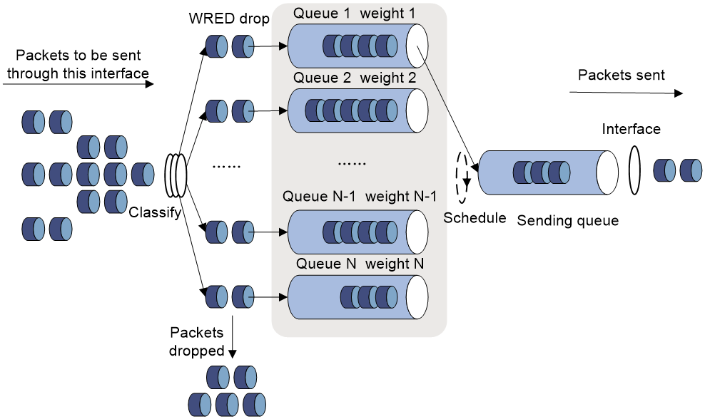
· A flow with a smaller queue size has a lower packet drop probability.
· A flow with a larger queue size has a higher packet drop probability.
In this way, the benefits of the flow with a smaller queue size are protected.
ECN
By dropping packets, WRED alleviates the influence of congestion on the network. However, the network resources for transmitting packets from the sender to the device which drops the packets are wasted. When congestion occurs, it is a better idea to perform the following actions:
· Inform the sender of the congestion status.
· Have the sender proactively slow down the packet sending rate or decrease the window size of packets.
This better utilizes the network resources.
RFC 2481 defined an end-to-end congestion notification mechanism named Explicit Congestion Notification (ECN). ECN uses the DS field in the IP header to mark the congestion status along the packet transmission path. An ECN-capable terminal can determine whether congestion occurs on the transmission path according to the packet contents. Then, it adjusts the packet sending speed to avoid deteriorating congestion. ECN defines the last two bits (ECN field) in the DS field of the IP header as follows:
· Bit 6 indicates whether the sending terminal device supports ECN, and is called the ECN-Capable Transport (ECT) bit.
· Bit 7 indicates whether the packet has experienced congestion along the transmission path, and is called the Congestion Experienced (CE) bit.
For more information about the DS field, see "Appendixes."
In actual applications, the following packets are considered as packets that an ECN-capable endpoint transmits:
· Packets with ECT set to 1 and CE set to 0.
· Packets with ECT set to 0 and CE set to 1.
After you enable ECN on a device, the device processes incoming packets as follows:
· When the device assigns packets to a queue in the outbound direction, if the average queue size is below the lower threshold (ECN threshold), the device does not process these packets, and directly forwards them out of the outgoing interface.
· When the device assigns packets to a queue in the outbound direction, if the average queue size is between the lower threshold and the upper threshold, the device performs the following operations:
¡ If the ECN field is 00, which shows that the packets are sent out of an ECN-incapable terminal, the device calculates whether to drop a packet according to the drop probability.
¡ If the ECN field is 01 or 10, which shows that the packets are sent out of an ECN-capable terminal, the device performs the following operations:
- Sets both the ECT bit and the CE bit to 1 for some of these packets according to the drop probability and forwards these packets.
- Forwards all incoming packets.
¡ If the ECN field is 11 in a packet, the device forwards the packet without modifying the ECN field. The combination of ECT bit 1 and CE bit 1 indicates that the packet has experienced congestion along the transmission path.
· When the device assigns packets to a queue in the outbound direction, if the average queue size exceeds the upper threshold, the device performs the following operations:
¡ If the ECN field is 00, which shows that the packets are sent out of an ECN-incapable terminal, the device drops the packets.
¡ If the ECN field is 01 or 10, which shows that the packets are sent out of an ECN-capable terminal, the device performs the following operations:
- Sets both the ECT bit and the CE bit to 1 for some of these packets according to the drop probability and forwards these packets.
- Forwards all incoming packets.
¡ If the ECN field is 11 in a packet, the device forwards the packet without modifying the ECN field. The combination of ECT bit 1 and CE bit 1 indicates that the packet has experienced congestion along the transmission path.
WRED configuration approaches
You can configure WRED by using one of the following approaches:
· WRED table configuration—Configure a WRED table in system view and then apply the WRED table to an interface.
· Global WRED Smart ECN—Enable global WRED Smart ECN in system view. The device adjusts ECN triggering thresholds based on traffic patterns (see "Enabling global WRED Smart ECN").
WRED parameters
Determine the following parameters before configuring WRED:
· Drop precedence—A parameter used for packet drop. The value 0 corresponds to green packets, the value 1 corresponds to yellow packets, and the value 2 corresponds to red packets. Red packets are dropped preferentially.
· Exponent for average queue size calculation—The greater the exponent, the less sensitive the average queue size is to real-time queue size changes. The formula for calculating the average queue size is:
Average queue size = ( previous average queue size x (1 – 2–n) ) + (current queue size x 2–n), where n is the exponent.
· Drop probability—Drop probability in percentage. The greater the value, the higher the drop probability.
Restrictions and guidelines: WRED configuration
On an interface, Configuring WRED parameters for a queue and Configuring and applying a queue-based WRED table are mutually exclusive. Please perform one of the two tasks.
Enabling global WRED Smart ECN and enabling ECN for a queue are mutually exclusive. Please perform one of the two tasks.
Enabling global WRED Smart ECN and Configuring and applying a queue-based WRED table are mutually exclusive. Please perform one of the two tasks.
Configuring WRED parameters for a queue
|
|
IMPORTANT: This feature is supported only in Release 6635 and later. |
1. Enter system view.
system-view
2. Enter interface view.
interface interface-type interface-number
3. Configuring WRED parameters for a queue.
qos wred queue queue-id low-limit low-limit high-limit high-limit [ discard-probability discard-prob ] [ ecn ] [ weighting-constant exponent ]
qos wred queue queue-id [ drop-level drop-level ] low-limit low-limit high-limit high-limit [ discard-probability discard-prob ]
By default, no WRED parameters are set for a queue.
4. Enable ECN for a queue.
qos wred queue queue-id ecn
By default, ECN is disabled for a queue.
5. Set the WRED exponent for average queue size calculation.
qos wred queue queue-id weighting-constant exponent
By default, the WRED exponent for average queue size calculation is 9.
Configuring and applying a queue-based WRED table
Restrictions and guidelines
By using a WRED table, WRED randomly drops packets during congestion based on the queues that hold packets.
One WRED table can be applied to multiple interfaces. You can modify the parameters of a WRED table applied to an interface, but you cannot delete the WRED table.
The term "interface" in this section collectively refers to Layer 2 and Layer 3 Ethernet interfaces. You can use the port link-mode command to configure an Ethernet port as a Layer 2 or Layer 3 interface (see Layer 2—LAN Switching Configuration Guide).
Procedure
1. Enter system view.
system-view
2. Create a WRED table and enter its view.
qos wred queue table table-name
3. (Optional.) Set the WRED exponent for average queue size calculation.
queue queue-id weighting-constant exponent
The default setting is 9.
4. (Optional.) Configure the other WRED parameters.
queue queue-id [ drop-level drop-level ] low-limit low-limit high-limit high-limit [ discard-probability discard-prob ]
By default, the lower limit is 100, the higher limit is 1000, and the drop probability is 10%.
5. (Optional.) Enable ECN for a queue.
queue queue-id ecn
By default, ECN is disabled for a queue.
6. Return to system view.
quit
7. Enter interface view.
interface interface-type interface-number
8. Apply the WRED table to the interface.
qos wred apply [ table-name ]
By default, no WRED table is applied to an interface, and tail drop is used on an interface.
Example: Configuring and applying a queue-based WRED table
Network configuration
Apply a WRED table to Twenty-FiveGigE 1/0/2, so that the packets are dropped as follows when congestion occurs:
· For the interface to preferentially forward higher-priority traffic, set a lower drop probability for a queue with a greater queue number. Set different drop parameters for queue 0, queue 3, and queue 7.
· Drop packets according to their colors.
¡ In queue 0, set the drop probability to 25%, 50%, and 75% for green, yellow, and red packets, respectively.
¡ In queue 3, set the drop probability to 5%, 10%, and 25% for green, yellow, and red packets, respectively.
¡ In queue 7, set the drop probability to 1%, 5%, and 10% for green, yellow, and red packets, respectively.
· Enable ECN for queue 7.
Procedure
# Configure a queue-based WRED table, and set different drop parameters for packets with different drop levels in different queues.
<Sysname> system-view
[Sysname] qos wred queue table queue-table1
[Sysname-wred-table-queue-table1] queue 0 drop-level 0 low-limit 128 high-limit 512 discard-probability 25
[Sysname-wred-table-queue-table1] queue 0 drop-level 1 low-limit 128 high-limit 512 discard-probability 50
[Sysname-wred-table-queue-table1] queue 0 drop-level 2 low-limit 128 high-limit 512 discard-probability 75
[Sysname-wred-table-queue-table1] queue 3 drop-level 0 low-limit 256 high-limit 640 discard-probability 5
[Sysname-wred-table-queue-table1] queue 3 drop-level 1 low-limit 256 high-limit 640 discard-probability 10
[Sysname-wred-table-queue-table1] queue 3 drop-level 2 low-limit 256 high-limit 640 discard-probability 25
[Sysname-wred-table-queue-table1] queue 7 drop-level 0 low-limit 512 high-limit 1024 discard-probability 1
[Sysname-wred-table-queue-table1] queue 7 drop-level 1 low-limit 512 high-limit 1024 discard-probability 5
[Sysname-wred-table-queue-table1] queue 7 drop-level 2 low-limit 512 high-limit 1024 discard-probability 10
[Sysname-wred-table-queue-table1] queue 7 ecn
[Sysname-wred-table-queue-table1] quit
# Apply the queue-based WRED table to Twenty-FiveGigE 1/0/2.
[Sysname] interface twenty-fivegige 1/0/2
[Sysname-Twenty-FiveGigE1/0/2] qos wred apply queue-table1
[Sysname-Twenty-FiveGigE1/0/2] quit
Enabling global WRED Smart ECN
About this task
As shown in Figure 19, in a distributed file system, to request a logical data block that is distributed on multiple servers, a client will send TCP requests to the servers at the same time. Each server will immediately send the requested data blocks to the client upon receiving a request. This N:1 (N:1 is called the Incast value) transmission mode easily causes congestion on the network device, and in the worst case, causes packet loss and TCP retransmission.
Figure 19 N:1 transmission mode
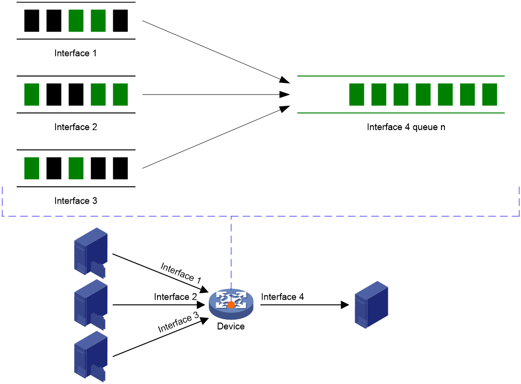
In addition, if the device is configured with PFC, PFC back pressure is triggered (the upstream device stops sending data) when the queue length reaches the PFC threshold. When PFC back pressure is removed, the upstream device starts sending data again. Stopping and starting traffic sending repeatedly reduces the bandwidth efficiency.
A possible solution is to set appropriate WRED parameters so ECN instead of PFC is triggered before serious congestion occurs. ECN enables the data source to reduce transmission rates.
Figure 20 PFC and ECN
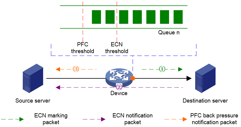
However, WRED parameters cannot adapt to changing traffic sizes. To solve this problem, Smart ECN is introduced.
Smart ECN can adjust WRED parameters based on traffic patterns as follows:
· If the Incast value is large, it reduces the ECN triggering threshold to minimize the possibility of PFC triggering while achieving low delay.
· If the Incast value is small, it increases the ECN triggering threshold to ensure high throughput.
· If the percentage of mice flows in a queue is high, it reduces the ECN triggering threshold to ensure low delay for most mice flows.
· If the percentage of elephant flows in a queue is high, it increases the ECN triggering threshold to ensure high throughput for most elephant flows.
Restrictions and guidelines
This function is supported only in Release 6635 and later.
This function is mutually exclusive with the function of applying a WRED table to an interface.
On a queue, this function is mutually exclusive with the function of enabling ECN.
Procedure
1. Enter system view.
system-view
2. Enable Smart ECN globally.
qos wred smart-ecn queue queue-id enable
The default for this command depends on the device model.
Display and maintenance commands for WRED
Execute display commands in any view.
|
Task |
Command |
|
Display WRED configuration and statistics for an interface. |
display qos wred interface [ interface-type interface-number ] |
|
Display the configuration of a WRED table or all WRED tables. |
display qos wred table [ name table-name ] [ slot slot-number ] |
Configuring traffic filtering
About traffic filtering
You can filter in or filter out traffic of a class by associating the class with a traffic filtering action. For example, you can filter packets sourced from an IP address according to network status.
Restrictions and guidelines: Traffic filtering configuration
A traffic filtering action does not take effect if the QoS policy is applied to a control plane.
Procedure
1. Enter system view.
system-view
2. Define a traffic class.
a. Create a traffic class and enter traffic class view.
traffic classifier classifier-name [ operator { and | or } ]
b. Configure a match criterion.
if-match match-criteria
By default, no match criterion is configured.
For more information about configuring match criteria, see ACL and QoS Command Reference.
c. Return to system view.
quit
3. Define a traffic behavior.
a. Create a traffic behavior and enter traffic behavior view.
traffic behavior behavior-name
b. Configure the traffic filtering action.
filter { deny | none | permit }
By default, no traffic filtering action is configured.
If a traffic behavior has the filter deny action, all other actions in the traffic behavior except class-based accounting do not take effect.
If the filter none command is configured in a traffic behavior, the permitted packets will not be processed by any other class-behavior associations in the same QoS policy.
If the filter permit command is configured in a traffic behavior, the permitted packets can be processed by other class-behavior associations in the same QoS policy.
c. Return to system view.
quit
4. Define a QoS policy.
a. Create a QoS policy and enter QoS policy view.
qos policy policy-name
b. Associate the traffic class with the traffic behavior in the QoS policy.
classifier classifier-name behavior behavior-name
By default, a traffic class is not associated with a traffic behavior.
c. Return to system view.
quit
5. Apply the QoS policy.
For more information, see "Applying the QoS policy."
By default, no QoS policy is applied.
6. (Optional.) Display the traffic filtering configuration.
display traffic behavior user-defined [ behavior-name ]
This command is available in any view.
Traffic filtering configuration examples
Example: Configuring traffic filtering
Network configuration
As shown in Figure 21, configure traffic filtering on Twenty-FiveGigE 1/0/1 to deny the incoming packets with a source port number other than 21.
![]()
Procedure
# Create advanced ACL 3000, and configure a rule to match packets whose source port number is not 21.
<Device> system-view
[Device] acl advanced 3000
[Device-acl-ipv4-adv-3000] rule 0 permit tcp source-port neq 21
[Device-acl-ipv4-adv-3000] quit
# Create a traffic class named classifier_1, and use ACL 3000 as the match criterion in the traffic class.
[Device] traffic classifier classifier_1
[Device-classifier-classifier_1] if-match acl 3000
[Device-classifier-classifier_1] quit
# Create a traffic behavior named behavior_1, and configure the traffic filtering action to drop packets.
[Device] traffic behavior behavior_1
[Device-behavior-behavior_1] filter deny
[Device-behavior-behavior_1] quit
# Create a QoS policy named policy, and associate traffic class classifier_1 with traffic behavior behavior_1 in the QoS policy.
[Device] qos policy policy
[Device-qospolicy-policy] classifier classifier_1 behavior behavior_1
[Device-qospolicy-policy] quit
# Apply QoS policy policy to the incoming traffic of Twenty-FiveGigE 1/0/1.
[Device] interface twenty-fivegige 1/0/1
[Device-Twenty-FiveGigE1/0/1] qos apply policy policy inbound
Example: Configuring traffic filtering with the none action
Network configuration
As shown in Figure 22, configure traffic filtering and traffic mirroring to mirror the incoming packets matching the following conditions on Twenty-FiveGigE 1/0/2 to Twenty-FiveGigE 1/0/1:
· DSCP priority is 34.
· UDP destination port number is 4791.
· The two bytes after the 8th byte starting from the Layer 4 header are not all-0s or all-1s.

Procedure
# Create user-defined ACL 5000, and configure rules to match packets with the following attributes:
· The DSCP value is 34.
· The UDP destination port number is 4791.
· The two bytes after the 8th byte starting from the Layer 4 header are all-0s or all-1s.
<Device> system-view
[Device] acl user-defined 5000
[Device-acl-user-5000] rule 0 permit udp dscp 34 destination-port eq 4791 l4 00 ff 8
[Device-acl-user-5000] rule 5 permit udp dscp 34 destination-port eq 4791 l4 ff ff 8
[Device-acl-user-5000] quit
# Create a traffic class named classifier_1, and use ACL 5000 as the match criterion.
[Device] traffic classifier classifier_1
[Device-classifier-classifier_1] if-match acl user-defined 5000
[Device-classifier-classifier_1] quit
# Create a traffic behavior named behavior_1, and configure the traffic filtering action as none. The packets permitted by the none action will not be processed by any other class-behavior associations in the same QoS policy.
[Device] traffic behavior behavior_1
[Device-behavior-behavior_1] filter none
[Device-behavior-behavior_1] quit
# Create user-defined ACL 5001, and configure rules to match packets with DSCP value 34 and UDP destination port number 4791.
<Device> system-view
[Device] acl user-defined 5001
[Device-acl-user-5001] rule 0 permit udp dscp 34 destination-port eq 4791
[Device-acl-user-5001] quit
# Create a traffic class named classifier_2, and use ACL 5001 as the match criterion.
[Device] traffic classifier classifier_2
[Device-classifier-classifier_2] if-match acl user-defined 5001
[Device-classifier-classifier_2] quit
# Create a traffic behavior named behavior_2, and configure the action of mirroring traffic to Twenty-FiveGigE 1/0/1.
[Device] traffic behavior behavior_2
[Device-behavior-behavior_2] mirror-to interface twenty-fivegige 1/0/1
[Device-behavior-behavior_2] quit
# Create a QoS policy named policy, and associate traffic classes classifier_1 and classifier_2 with traffic behaviors behavior_1 and behavior_2, respectively.
[Device] qos policy policy
[Device-qospolicy-policy] classifier classifier_1 behavior behavior_1
[Device-qospolicy-policy] classifier classifier_2 behavior behavior_2
[Device-qospolicy-policy] quit
# Apply QoS policy policy to the incoming traffic of Twenty-FiveGigE 1/0/2.
[Device] interface twenty-fivegige 1/0/2
[Device-Twenty-FiveGigE1/0/2] qos apply policy policy inbound
Configuring priority marking
About priority marking
Priority marking sets the priority fields or flag bits of packets to modify the priority of packets. For example, you can use priority marking to set IP precedence or DSCP for a class of IP packets to control the forwarding of these packets.
1. Configure a traffic behavior with a priority marking action.
2. Associate the traffic class with the traffic behavior.
Priority marking can be used together with priority mapping. For more information, see "Configuring priority mapping."
Configuring priority marking
Restrictions and guidelines
A priority marking action does not take effect if the QoS policy is applied to a control plane.
Procedure
1. Enter system view.
system-view
2. Define a traffic class.
a. Create a traffic class and enter traffic class view.
traffic classifier classifier-name [ operator { and | or } ]
b. Configure a match criterion.
if-match match-criteria
By default, no match criterion is configured.
For more information about the if-match command, see ACL and QoS Command Reference.
c. Return to system view.
quit
3. Define a traffic behavior.
a. Create a traffic behavior and enter traffic behavior view.
traffic behavior behavior-name
b. Configure a priority marking action.
For configurable priority marking actions, see the remark commands in ACL and QoS Command Reference.
c. Return to system view.
quit
4. Define a QoS policy.
a. Create a QoS policy and enter QoS policy view.
qos policy policy-name
b. Associate the traffic class with the traffic behavior in the QoS policy.
classifier classifier-name behavior behavior-name
By default, a traffic class is not associated with a traffic behavior.
c. Return to system view.
quit
5. Apply the QoS policy.
For more information, see "Applying the QoS policy."
By default, no QoS policy is applied.
6. (Optional.) Display the priority marking configuration.
display traffic behavior user-defined [ behavior-name ]
This command is available in any view.
Priority marking configuration examples
Example: Configuring priority marking
Network configuration
As shown in Figure 23, configure priority marking on the device to meet the following requirements:
|
Traffic source |
Destination |
Processing priority |
|
Host A, B |
Data server |
High |
|
Host A, B |
Mail server |
Medium |
|
Host A, B |
File server |
Low |
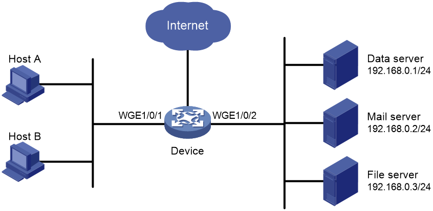
Procedure
# Create advanced ACL 3000, and configure a rule to match packets with destination IP address 192.168.0.1.
<Device> system-view
[Device] acl advanced 3000
[Device-acl-ipv4-adv-3000] rule permit ip destination 192.168.0.1 0
[Device-acl-ipv4-adv-3000] quit
# Create advanced ACL 3001, and configure a rule to match packets with destination IP address 192.168.0.2.
[Device] acl advanced 3001
[Device-acl-ipv4-adv-3001] rule permit ip destination 192.168.0.2 0
[Device-acl-ipv4-adv-3001] quit
# Create advanced ACL 3002, and configure a rule to match packets with destination IP address 192.168.0.3.
[Device] acl advanced 3002
[Device-acl-ipv4-adv-3002] rule permit ip destination 192.168.0.3 0
[Device-acl-ipv4-adv-3002] quit
# Create a traffic class named classifier_dbserver, and use ACL 3000 as the match criterion in the traffic class.
[Device] traffic classifier classifier_dbserver
[Device-classifier-classifier_dbserver] if-match acl 3000
[Device-classifier-classifier_dbserver] quit
# Create a traffic class named classifier_mserver, and use ACL 3001 as the match criterion in the traffic class.
[Device] traffic classifier classifier_mserver
[Device-classifier-classifier_mserver] if-match acl 3001
[Device-classifier-classifier_mserver] quit
# Create a traffic class named classifier_fserver, and use ACL 3002 as the match criterion in the traffic class.
[Device] traffic classifier classifier_fserver
[Device-classifier-classifier_fserver] if-match acl 3002
[Device-classifier-classifier_fserver] quit
# Create a traffic behavior named behavior_dbserver, and configure the action of setting the local precedence value to 4.
[Device] traffic behavior behavior_dbserver
[Device-behavior-behavior_dbserver] remark local-precedence 4
[Device-behavior-behavior_dbserver] quit
# Create a traffic behavior named behavior_mserver, and configure the action of setting the local precedence value to 3.
[Device] traffic behavior behavior_mserver
[Device-behavior-behavior_mserver] remark local-precedence 3
[Device-behavior-behavior_mserver] quit
# Create a traffic behavior named behavior_fserver, and configure the action of setting the local precedence value to 2.
[Device] traffic behavior behavior_fserver
[Device-behavior-behavior_fserver] remark local-precedence 2
[Device-behavior-behavior_fserver] quit
# Create a QoS policy named policy_server, and associate traffic classes with traffic behaviors in the QoS policy.
[Device] qos policy policy_server
[Device-qospolicy-policy_server] classifier classifier_dbserver behavior behavior_dbserver
[Device-qospolicy-policy_server] classifier classifier_mserver behavior behavior_mserver
[Device-qospolicy-policy_server] classifier classifier_fserver behavior behavior_fserver
[Device-qospolicy-policy_server] quit
# Apply QoS policy policy_server to the incoming traffic of Twenty-FiveGigE 1/0/1.
[Device] interface twenty-fivegige 1/0/1
[Device-Twenty-FiveGigE1/0/1] qos apply policy policy_server inbound
[Device-Twenty-FiveGigE1/0/1] quit
Configuring nesting
About nesting
Nesting adds a VLAN tag to the matching packets to allow the VLAN-tagged packets to pass through the corresponding VLAN. For example, you can add an outer VLAN tag to packets from a customer network to a service provider network. This allows the packets to pass through the service provider network by carrying a VLAN tag assigned by the service provider.
Restrictions and guidelines: Nesting configuration
An outer VLAN tag adding action takes effect only if the QoS policy is applied to the inbound direction of an interface.
To use the nesting action to add an outer VLAN tag to packets, first enable QinQ in interface view. With QinQ enabled, you must use the if-match customer-vlan-id vlan-id-list command to match single-tagged packets. Then, you can add an outer VLAN tag to the matching packets.
Procedure
1. Enter system view.
system-view
2. Define a traffic class.
a. Create a traffic class and enter traffic class view.
traffic classifier classifier-name [ operator { and | or } ]
b. Configure a match criterion.
if-match match-criteria
By default, no match criterion is configured for a traffic class.
For more information about the match criteria, see the if-match command in ACL and QoS Command Reference.
c. Return to system view.
quit
3. Define a traffic behavior.
a. Create a traffic behavior and enter traffic behavior view.
traffic behavior behavior-name
b. Configure an outer VLAN tag adding action.
nest top-most vlan vlan-id
By default, no outer VLAN tag adding action is configured for a traffic behavior.
c. Return to system view.
quit
4. Define a QoS policy.
a. Create a QoS policy and enter QoS policy view.
qos policy policy-name
b. Associate the traffic class with the traffic behavior in the QoS policy.
classifier classifier-name behavior behavior-name
By default, a traffic class is not associated with a traffic behavior.
c. Return to system view.
quit
5. Enable QinQ on an interface.
a. Enter Layer 2 Ethernet or aggregate interface view.
interface interface-type interface-number
b. Enable QinQ on the interface.
qinq enable
By default, QinQ is disabled on an interface.
6. Apply the QoS policy.
For more information, see "Applying the QoS policy."
By default, no QoS policy is applied.
7. (Optional.) Display the nesting configuration.
display traffic behavior user-defined [ behavior-name ]
This command is available in any view.
Nesting configuration examples
Example: Configuring nesting
Network configuration
As shown in Figure 24:
· Site 1 and Site 2 in VPN A are two branches of a company. They use VLAN 5 to transmit traffic.
· Because Site 1 and Site 2 are located in different areas, the two sites use the VPN access service of a service provider. The service provider assigns VLAN 100 to the two sites.
Configure nesting, so that the two branches can communicate through the service provider network.
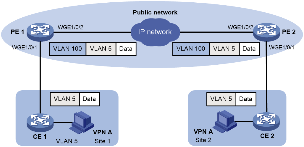
Procedure
1. Configuring PE 1:
# Create a traffic class named test to match traffic with VLAN ID 5.
<PE1> system-view
[PE1] traffic classifier test
[PE1-classifier-test] if-match customer-vlan-id 5
[PE1-classifier-test] quit
# Configure an action to add outer VLAN tag 100 in traffic behavior test.
[PE1] traffic behavior test
[PE1-behavior-test] nest top-most vlan 100
[PE1-behavior-test] quit
# Create a QoS policy named test, and associate class test with behavior test in the QoS policy.
[PE1] qos policy test
[PE1-qospolicy-test] classifier test behavior test
[PE1-qospolicy-test] quit
# Configure the downlink port (Twenty-FiveGigE 1/0/1) as a hybrid port, and assign the port to VLAN 100 as an untagged member.
[PE1] interface twenty-fivegige 1/0/1
[PE1-Twenty-FiveGigE1/0/1] port link-type hybrid
[PE1-Twenty-FiveGigE1/0/1] port hybrid vlan 100 untagged
# Enable QinQ on Twenty-FiveGigE 1/0/1.
[PE1-Twenty-FiveGigE1/0/1] qinq enable
# Apply QoS policy test to the incoming traffic of Twenty-FiveGigE 1/0/1.
[PE1-Twenty-FiveGigE1/0/1] qos apply policy test inbound
[PE1-Twenty-FiveGigE1/0/1] quit
# Configure the uplink port (Twenty-FiveGigE 1/0/2) as a trunk port, and assign it to VLAN 100.
[PE1] interface twenty-fivegige 1/0/2
[PE1-Twenty-FiveGigE1/0/2] port link-type trunk
[PE1-Twenty-FiveGigE1/0/2] port trunk permit vlan 100
[PE1-Twenty-FiveGigE1/0/2] quit
2. Configuring PE 2:
Configure PE 2 in the same way PE 1 is configured.
Configuring traffic redirecting
About traffic redirecting
Traffic redirecting redirects packets matching the specified match criteria to a location for processing.
You can redirect packets to the following destinations:
· CPU.
· Interface.
· Tunnel group.
For information about tunnel groups, see tunneling configuration in Layer 3—IP Services Configuration Guide.
Restrictions and guidelines: Traffic redirecting configuration
· A traffic redirecting action takes effect only if the QoS policy is applied to the inbound direction of the following application destinations:
¡ Ethernet service instance
¡ Interface.
¡ VLANs.
¡ Globally.
¡ User profile.
· If you execute the redirect command multiple times, the most recent configuration takes effect.
· For traffic redirecting to an Ethernet interface, the switch does not display the redirecting action after the interface expansion card that hosts the interface is removed. After the interface module or interface expansion card is reinserted, the switch can display the redirecting action.
· Redirecting traffic to an interface takes effect only on Layer 2 forwarded packets.
Procedure
1. Enter system view.
system-view
2. Define a traffic class.
a. Create a traffic class and enter traffic class view.
traffic classifier classifier-name [ operator { and | or } ]
b. Configure a match criterion.
if-match match-criteria
By default, no match criterion is configured for a traffic class.
For more information about the match criteria, see the if-match command in ACL and QoS Command Reference.
c. Return to system view.
quit
3. Define a traffic behavior.
a. Create a traffic behavior and enter traffic behavior view.
traffic behavior behavior-name
b. Configure a traffic redirecting action.
redirect { cpu | interface interface-type interface-number | tunnel-group group-id }
By default, no traffic redirecting action is configured for a traffic behavior.
c. Return to system view.
quit
4. Define a QoS policy.
a. Create a QoS policy and enter QoS policy view.
qos policy policy-name
b. Associate the traffic class with the traffic behavior in the QoS policy.
classifier classifier-name behavior behavior-name
By default, a traffic class is not associated with a traffic behavior.
c. Return to system view.
quit
5. Apply the QoS policy.
For more information, see "Applying the QoS policy."
By default, no QoS policy is applied.
6. (Optional.) Display traffic redirecting configuration.
display traffic behavior user-defined [ behavior-name ]
This command is available in any view.
Traffic redirecting configuration examples
Example: Configuring traffic redirecting
Network configuration
As shown in Figure 25:
· Device A is connected to Device B through two links. Device A and Device B are each connected to other devices.
· Twenty-FiveGigE 1/0/1 of Device A is a trunk port and belongs to VLAN 200 and VLAN 201.
· Twenty-FiveGigE 1/0/2 of Device A and Twenty-FiveGigE 1/0/2 of Device B belong to VLAN 200.
· Twenty-FiveGigE 1/0/3 of Device A and Twenty-FiveGigE 1/0/3 of Device B belong to VLAN 201.
· On Device A, the IP address of VLAN-interface 200 is 200.1.1.1/24, and that of VLAN-interface 201 is 201.1.1.1/24.
· On Device B, the IP address of VLAN-interface 200 is 200.1.1.2/24, and that of VLAN-interface 201 is 201.1.1.2/24.
Configure the actions of redirecting traffic to an interface to meet the following requirements:
· Packets with source IP address 2.1.1.1 received on Twenty-FiveGigE 1/0/1 of Device A are forwarded to Twenty-FiveGigE 1/0/2.
· Packets with source IP address 2.1.1.2 received on Twenty-FiveGigE 1/0/1 of Device A are forwarded to Twenty-FiveGigE 1/0/3.
· Other packets received on Twenty-FiveGigE 1/0/1 of Device A are forwarded according to the routing table.

Procedure
# Create basic ACL 2000, and configure a rule to match packets with source IP address 2.1.1.1.
<DeviceA> system-view
[DeviceA] acl basic 2000
[DeviceA-acl-ipv4-basic-2000] rule permit source 2.1.1.1 0
[DeviceA-acl-ipv4-basic-2000] quit
# Create basic ACL 2001, and configure a rule to match packets with source IP address 2.1.1.2.
[DeviceA] acl basic 2001
[DeviceA-acl-ipv4-basic-2001] rule permit source 2.1.1.2 0
[DeviceA-acl-ipv4-basic-2001] quit
# Create a traffic class named classifier_1, and use ACL 2000 as the match criterion in the traffic class.
[DeviceA] traffic classifier classifier_1
[DeviceA-classifier-classifier_1] if-match acl 2000
[DeviceA-classifier-classifier_1] quit
# Create a traffic class named classifier_2, and use ACL 2001 as the match criterion in the traffic class.
[DeviceA] traffic classifier classifier_2
[DeviceA-classifier-classifier_2] if-match acl 2001
[DeviceA-classifier-classifier_2] quit
# Create a traffic behavior named behavior_1, and configure the action of redirecting traffic to Twenty-FiveGigE 1/0/2.
[DeviceA] traffic behavior behavior_1
[DeviceA-behavior-behavior_1] redirect interface twenty-fivegige 1/0/2
[DeviceA-behavior-behavior_1] quit
# Create a traffic behavior named behavior_2, and configure the action of redirecting traffic to Twenty-FiveGigE 1/0/3.
[DeviceA] traffic behavior behavior_2
[DeviceA-behavior-behavior_2] redirect interface twenty-fivegige 1/0/3
[DeviceA-behavior-behavior_2] quit
# Create a QoS policy named policy.
[DeviceA] qos policy policy
# Associate traffic class classifier_1 with traffic behavior behavior_1 in the QoS policy.
[DeviceA-qospolicy-policy] classifier classifier_1 behavior behavior_1
# Associate traffic class classifier_2 with traffic behavior behavior_2 in the QoS policy.
[DeviceA-qospolicy-policy] classifier classifier_2 behavior behavior_2
[DeviceA-qospolicy-policy] quit
# Apply QoS policy policy to the incoming traffic of Twenty-FiveGigE 1/0/1.
[DeviceA] interface twenty-fivegige 1/0/1
[DeviceA-Twenty-FiveGigE1/0/1] qos apply policy policy inbound
Configuring aggregate CAR
About aggregate CAR
An aggregate CAR action is created globally. It can be directly applied to interfaces or used in the traffic behaviors associated with different traffic classes to police multiple traffic flows as a whole. The total rate of the traffic flows must conform to the traffic policing specifications set in the aggregate CAR action.
Restrictions and guidelines: Aggregate CAR configuration
When a QoS policy containing an aggregation CAR is applied to the inbound direction of multiple interfaces, the actual rate limit that takes effect depends on the interface groups of these interfaces. By default, the actual rate limit that takes effect is the CIR plus the PIR specified in the aggregation CAR action multiplied by the number of involved interface groups. Interfaces on different IRF member devices belong to different port groups. To identify port group information, execute the debug port mapping command for the specified slot in probe view. Interfaces with the same Unit and PipeNum values belong to the same port group.
Configuring aggregate CAR
1. Enter system view.
system-view
2. Define a traffic class.
a. Create a traffic class and enter traffic class view.
traffic classifier classifier-name [ operator { and | or } ]
b. Configure a match criterion.
if-match match-criteria
By default, no match criterion is configured.
For configurable match criteria, see the if-match command in ACL and QoS Command Reference.
c. Return to system view.
quit
3. Configure an aggregate CAR action.
qos car car-name aggregative cir committed-information-rate [ cbs committed-burst-size [ ebs excess-burst-size ] ] [ green action | red action | yellow action ] *
qos car car-name aggregative cir committed-information-rate [ cbs committed-burst-size ] pir peak-information-rate [ ebs excess-burst-size ] [ green action | red action | yellow action ] *
By default, no aggregate CAR action is configured.
4. Define a traffic behavior.
a. Enter traffic behavior view.
traffic behavior behavior-name
b. Use the aggregate CAR in the traffic behavior.
car name car-name
By default, no aggregate CAR action is used in a traffic behavior.
5. Apply the QoS policy.
For more information, see "Applying the QoS policy."
By default, no QoS policy is applied.
Display and maintenance commands for aggregate CAR
Execute display commands in any view and reset commands in user view.
|
Task |
Command |
|
Display statistics for aggregate CAR actions. |
display qos car name [ car-name ] |
|
Clear statistics for aggregate CAR actions. |
reset qos car name [ car-name ] |
Distinguishing elephant and mice flows
About elephant and mice flows
Traffic flows in a network generally fall into two categories: elephant flows and mice flows. An elephant flow is a long flow that requires high bandwidth but can has low requirements for delay, such as video download traffic. A mice flow is a short flow that requires low bandwidth but has high requirements for delay, such as query traffic.
This feature can identify elephant flows and assign a drop precedence, local precedence, or 802.1p priority value to these flows, thus improving application performance for mice flows.
Restrictions: Software version compatibility with distinguishing elephant and mice flows
This feature is supported only in Release 6616 and later.
Restrictions and guidelines: Elephant and mice flow distinguishing configuration
This feature must rely on the flow entries in the flow group feature to work, and the flow group mode must be elephant/mice flow mode. For more information about flow groups, see Telemetry Configuration Guide.
Procedure
1. Enter system view.
system-view
2. Enter elephant/mice flow view.
qos mice-elephant-flow
3. Configure the traffic thresholds to identify elephant flows.
elephant-flow rate rate [ gbps | kbps | mbps ] [ size size [ bytes | kbytes | mbytes ] ]
By default, no traffic thresholds are configured.
4. Configure an action to take on elephant flows.
elephant-flow action { drop-precedence drop-precedence-value | dot1p dot1p-value | local-precedence local-precedence-value | none }
By default, no action is configured.
Only the S6850 and S9850 switch series support this command.
The dot1p dot1p-value and local-precedence local-precedence-value options are supported only in Release 6635 and later.
Configuring interface packet accounting
About interface packet accounting
This feature can collect packet statistics on an interface by DSCP priority and ECN attribute.
Restrictions: Software version compatibility with interface packet accounting
This feature is supported only in Release 6616 and later.
Restrictions and guidelines: Interface packet accounting configuration
If you enable interface packet accounting by both DSCP and ECN attributes, the device counts all non-IP packets as DSCP 0 and ECN 0.
Procedure
1. Enter system view.
system-view
2. Enter interface view.
interface interface-type interface-number
3. Configure packet accounting on the interface.
qos packet-statistics inbound { dscp | ecn } *
By default, packet accounting is disabled on an interface.
Display and maintenance commands for interface packet accounting
Execute display commands in any view and reset commands in user view.
|
Task |
Command |
|
Display interface packet statistics. |
display qos packet-statistics interface interface-type interface-number inbound |
|
Clear interface packet statistics. |
reset qos packet-statistics interface [ interface-type interface-number ] [ inbound ] |
Configuring class-based accounting
About class-based accounting
Class-based accounting collects statistics on a per-traffic class basis. For example, you can define the action to collect statistics for traffic sourced from a certain IP address. By analyzing the statistics, you can determine whether anomalies have occurred and what action to take.
Procedure
1. Enter system view.
system-view
2. Define a traffic class.
a. Create a traffic class and enter traffic class view.
traffic classifier classifier-name [ operator { and | or } ]
b. Configure a match criterion.
if-match match-criteria
By default, no match criterion is configured.
For more information about the if-match command, see ACL and QoS Command Reference.
c. Return to system view.
quit
3. Define a traffic behavior.
a. Create a traffic behavior and enter traffic behavior view.
traffic behavior behavior-name
b. Configure an accounting action.
accounting [ byte | packet ] *
By default, no traffic accounting action is configured.
c. Return to system view.
quit
4. Define a QoS policy.
a. Create a QoS policy and enter QoS policy view.
qos policy policy-name
b. Associate the traffic class with the traffic behavior in the QoS policy.
classifier classifier-name behavior behavior-name
By default, a traffic class is not associated with a traffic behavior.
c. Return to system view.
quit
5. Apply the QoS policy.
For more information, see "Applying the QoS policy."
By default, no QoS policy is applied.
6. (Optional.) Display the class-based accounting configuration.
display traffic behavior user-defined [ behavior-name ]
Class-based accounting configuration examples
Example: Configuring class-based accounting
Network configuration
As shown in Figure 26, configure class-based accounting on Twenty-FiveGigE 1/0/1 to collect statistics for incoming traffic from 1.1.1.1/24.

Procedure
# Create basic ACL 2000, and configure a rule to match packets with source IP address 1.1.1.1.
<Device> system-view
[Device] acl basic 2000
[Device-acl-ipv4-basic-2000] rule permit source 1.1.1.1 0
[Device-acl-ipv4-basic-2000] quit
# Create a traffic class named classifier_1, and use ACL 2000 as the match criterion in the traffic class.
[Device] traffic classifier classifier_1
[Device-classifier-classifier_1] if-match acl 2000
[Device-classifier-classifier_1] quit
# Create a traffic behavior named behavior_1, and configure the class-based accounting action.
[Device] traffic behavior behavior_1
[Device-behavior-behavior_1] accounting packet
[Device-behavior-behavior_1] quit
# Create a QoS policy named policy, and associate traffic class classifier_1 with traffic behavior behavior_1 in the QoS policy.
[Device] qos policy policy
[Device-qospolicy-policy] classifier classifier_1 behavior behavior_1
[Device-qospolicy-policy] quit
# Apply QoS policy policy to the incoming traffic of Twenty-FiveGigE 1/0/1.
[Device] interface twenty-fivegige 1/0/1
[Device-Twenty-FiveGigE1/0/1] qos apply policy policy inbound
[Device-Twenty-FiveGigE1/0/1] quit
# Display traffic statistics to verify the configuration.
[Device] display qos policy interface twenty-fivegige 1/0/1
Interface: Twenty-FiveGigE1/0/1
Direction: Inbound
Policy: policy
Classifier: classifier_1
Operator: AND
Rule(s) :
If-match acl 2000
Behavior: behavior_1
Accounting enable:
28529 (Packets)
Configuring QPPB
About QPPB
The QoS Policy Propagation Through the Border Gateway Protocol (QPPB) feature enables you to classify IP packets based on the following attributes:
· BGP community lists.
· Prefix lists.
· BGP AS paths.
Application scenarios
QPPB minimizes the QoS policy configuration and management efforts on the BGP route receiver when the network topology changes. It is suitable for a large-scaled complex network.
The QPPB feature is implemented as follows:
· The BGP route sender preclassifies routes before advertising them.
· The BGP route receiver performs the following operations:
¡ Sets the IP precedence and local QoS ID for the routes.
¡ Takes appropriate QoS actions on the packets that match the routes.
QPPB is used in the following scenarios:
· Traffic classification based on destination IP addresses.
· Traffic classification based on IBGP and EBGP within an autonomous system or across multiple autonomous systems.
QPPB fundamentals
QPPB works on the BGP receiver by applying a QoS policy to BGP routes with the same local QoS ID. It depends on the BGP route sender to preclassify routes.
The BGP route sender uses a routing policy to set route attributes for BGP routes before advertising them.
The BGP receiver performs the following operations:
· Uses a routing policy to match routes based on these route attributes.
· Sets the local QoS ID for the matching routes.
The BGP receiver performs the following operations:
1. Compares the routes with the incoming route policy based on their BGP AS path, prefix, or community attributes.
2. Applies the local QoS ID to the matching routes.
3. Adds the BGP routes and their associated local QoS ID to the routing table.
4. Applies the local QoS ID to the packets destined to the IP address in the route.
5. Takes QoS actions on the packets according to the QoS priority settings.
QPPB tasks at a glance
To configure QPPB, perform the following tasks:
1. Configuring the route sender
a. Configuring basic BGP functions
b. (Optional.) Creating a routing policy
2. Configuring the route receiver
a. Configuring basic BGP functions
b. Configuring a routing policy
c. Enabling QPPB on the route receiving interface
Configuring the route sender
Configure the BGP route sender to set route attributes for routes before advertising them.
Configuring basic BGP functions
For more information, see Layer 3—IP Routing Configuration Guide.
Creating a routing policy
Configuring the route receiver
Configuring basic BGP functions
For more information, see Layer 3—IP Routing Configuration Guide.
Configuring a routing policy
Configure a routing policy to perform the following operations:
· Match the route attributes set by the route sender.
· Set the local QoS ID for the matching routes.
For more information, see Layer 3—IP Routing Configuration Guide.
Enabling QPPB on the route receiving interface
Restrictions and guidelines
For QPPB to work correctly, you must configure the QoS policy as follows:
· Use the local QoS ID set in the routing policy to match packets.
· Specify the mode qppb-manipulation keyword when associating a traffic behavior with a traffic class.
For more information about QoS policies, see "Configuring a QoS policy."
Procedure
1. Enter system view.
system-view
2. Enter interface view.
interface interface-type interface-number
3. Enable QPPB on the interface.
bgp-policy destination ip-qos-map }
By default, QPPB is disabled.
This command applies only to incoming traffic.
4. Apply a QoS policy to the interface.
qos apply policy policy-name { inbound | outbound }
By default, no QoS policy is applied to an interface.
QPPB configuration examples
Example: Configuring QPPB in an IPv4 network
Network configuration
As shown in Figure 27, all devices run BGP.
Configure QPPB so that Device B can perform the following operations:
· Receive routes.
· Set local QoS IDs according to the routing policy.
· Use the QoS policy to limit the traffic rate to 512000 kbps.
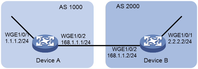
Procedure
1. Configure IP addresses for each interface. (Details not shown.)
2. Configure a BGP connection to Device B, and add the network 1.1.1.0/8 to the BGP routing table on Device A.
<DeviceA> system-view
[DeviceA] bgp 1000
[DeviceA-bgp] peer 168.1.1.2 as-number 2000
[DeviceA-bgp] peer 168.1.1.2 connect-interface twenty-fivegige 1/0/2
[DeviceA-bgp] address-family ipv4
[DeviceA-bgp-ipv4] import-route direct
[DeviceA-bgp-ipv4] peer 168.1.1.2 enable
[DeviceA-bgp-ipv4] quit
[DeviceA-bgp] quit
3. Configure Device B:
# Configure a BGP connection to Device A.
<DeviceB> system-view
[DeviceB] bgp 2000
[DeviceB-bgp] peer 168.1.1.1 as-number 1000
[DeviceB-bgp] peer 168.1.1.1 connect-interface twenty-fivegige 1/0/2
[DeviceB-bgp] address-family ipv4
[DeviceB-bgp-ipv4] peer 168.1.1.1 enable
[DeviceB-bgp-ipv4] peer 168.1.1.1 route-policy qppb import
[DeviceB-bgp-ipv4] quit
[DeviceB-bgp] quit
# Configure the routing policy qppb.
[DeviceB] route-policy qppb permit node 0
[DeviceB-route-policy-qppb-0] apply qos-local-id 3
[DeviceB-route-policy-qppb-0] quit
# Enable QPPB on Twenty-FiveGigE 1/0/2.
[DeviceB] interface twenty-fivegige 1/0/2
[DeviceB-Twenty-FiveGigE1/0/2] bgp-policy destination ip-qos-map
[DeviceB-Twenty-FiveGigE1/0/2] quit
# Configure a QoS policy.
[DeviceB] traffic classifier qppb
[DeviceB-classifier-qppb] if-match qos-local-id 3
[DeviceB-classifier-qppb] quit
[DeviceB] traffic behavior qppb
[DeviceB-behavior-qppb] car cir 512000 green pass red discard
[DeviceB-behavior-qppb] quit
[DeviceB] qos policy qppb
[DeviceB-qospolicy-qppb] classifier qppb behavior qppb mode qppb-manipulation
[DeviceB-qospolicy-qppb] quit
# Apply the QoS policy to incoming traffic on Twenty-FiveGigE 1/0/1.
[DeviceB] interface twenty-fivegige 1/0/1
[DeviceB-Twenty-FiveGigE1/0/1] qos apply policy qppb inbound
[DeviceB-Twenty-FiveGigE1/0/1] quit
Verifying the configuration
# Verify that the related route on Device B takes effect.
[DeviceB] display bgp routing-table ipv4 1.1.1.0
BGP local router ID: 168.1.1.2
Local AS number: 2000
Paths: 1 available, 1 best
BGP routing table information of 168.1.1.0/24:
From : 168.1.1.1 (168.1.1.1)
Rely nexthop : 168.1.1.1
Original nexthop: 168.1.1.1
Out interface : Twenty-FiveGigE1/0/2
Route age : 00h30m12s
OutLabel : NULL
RxPathID : 0x0
TxPathID : 0x0
AS-path : 1000
Origin : incomplete
Attribute value : MED 0, pref-val 0
State : valid, external, best
IP precedence : N/A
QoS local ID : 3
Traffic index : N/A
Tunnel policy : NULL
Rely tunnel IDs : N/A
# Display the QoS policy configuration on Twenty-FiveGigE 1/0/1 of Device B.
[DeviceB] display qos policy interface twenty-fivegige 1/0/1
Interface: Twenty-FiveGigE1/0/1
Direction: Inbound
Policy: qppb
Classifier: qppb
Mode: qppb-manipulation
Operator: AND
Rule(s) :
If-match qos-local-id 3
Behavior: qppb
Committed Access Rate:
CIR 512000 (kbps), CBS 32000000 (Bytes), EBS 0 (Bytes)
Green action : pass
Yellow action : pass
Red action : discard
Green packets : 0 (Packets) 0 (Bytes)
Yellow packets: 0 (Packets) 0 (Bytes)
Red packets : 0 (Packets) 0 (Bytes)
Example: Configuring QPPB in an MPLS L3VPN
Network configuration
As shown in Figure 28, all devices run BGP.
Configure QPPB so that Device C can perform the following operations:
· Receive routes.
· Set the QPPB local QoS IDs.
· Use the QoS policy to limit the traffic rate to 200000 kbps in each direction.
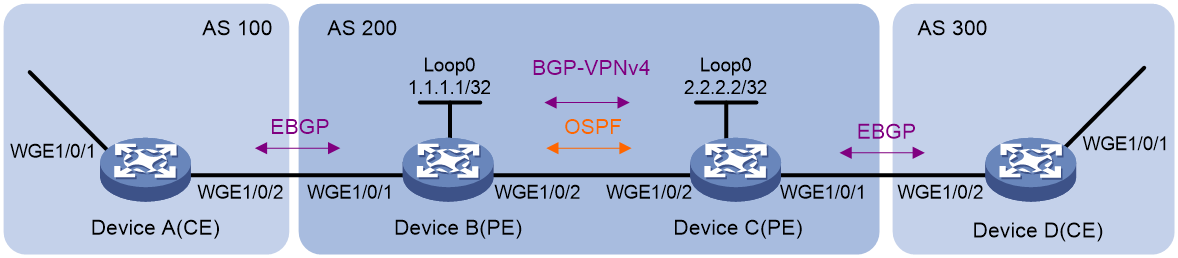
Table 2 Interfaces and IP address assignment
|
Device |
Interface |
IP address |
Device |
Interface |
IP address |
|
Device A |
WGE1/0/1 |
192.168.1.2/24 |
Device B |
WGE1/0/1 |
167.1.1.2/24 |
|
WGE1/0/2 |
167.1.1.1/24 |
WGE1/0/2 |
168.1.1.2/24 |
||
|
Device C |
WGE1/0/1 |
169.1.1.2/24 |
Device D |
WGE1/0/2 |
169.1.1.1/24 |
|
WGE1/0/2 |
168.1.1.1/24 |
WGE1/0/1 |
192.168.3.2/24 |
Procedure
1. Configure IP addresses for each interface. (Details not shown.)
2. Configure a BGP connection on Device A.
<DeviceA> system-view
[DeviceA] bgp 100
[DeviceA-bgp] peer 167.1.1.2 as-number 200
[DeviceA-bgp] peer 167.1.1.2 connect-interface twenty-fivegige 1/0/2
[DeviceA-bgp] address-family ipv4
[DeviceA-bgp-ipv4] import-route direct
[DeviceA-bgp-ipv4] peer 167.1.1.2 enable
[DeviceA-bgp-ipv4] quit
[DeviceA-bgp] quit
3. Configure Device B:
# Configure a VPN instance.
<DeviceB> system-view
[DeviceB] ip vpn-instance vpn1
[DeviceB-vpn-instance-vpn1] route-distinguisher 200:1
[DeviceB-vpn-instance-vpn1] vpn-target 200:1 export-extcommunity
[DeviceB-vpn-instance-vpn1] vpn-target 200:1 import-extcommunity
[DeviceB-vpn-instance-vpn1] quit
# Configure a BGP connection.
[DeviceB] router id 1.1.1.1
[DeviceB] bgp 200
[DeviceB-bgp] peer 2.2.2.2 as-number 200
[DeviceB-bgp] peer 2.2.2.2 connect-interface loopback 0
[DeviceB-bgp] ip vpn-instance vpn1
[DeviceB-bgp-vpn1] peer 167.1.1.1 as-number 100
[DeviceB-bgp-vpn1] address-family ipv4
[DeviceB-bgp-ipv4-vpn1] peer 167.1.1.1 enable
[DeviceB-bgp-ipv4-vpn1] quit
[DeviceB-bgp] address-family vpnv4
[DeviceB-bgp-vpnv4] peer 2.2.2.2 enable
[DeviceB-bgp-vpnv4] quit
[DeviceB-bgp] quit
# Configure MPLS.
[DeviceB] mpls lsr-id 1.1.1.1
[DeviceB] mpls ldp
[DeviceB-mpls-ldp] quit
# Configure OSPF.
[DeviceB] ospf
[DeviceB-ospf-1] area 0
[DeviceB-ospf-1-area-0.0.0.0] network 1.1.1.1 0.0.0.0
[DeviceB-ospf-1-area-0.0.0.0] network 168.1.1.0 0.0.0.255
[DeviceB-ospf-1-area-0.0.0.0] quit
[DeviceB-ospf-1] quit
# Bind Twenty-FiveGigE 1/0/1 to VPN instance vpn1.
[DeviceB] interface twenty-fivegige 1/0/1
[DeviceB-Twenty-FiveGigE1/0/1] ip binding vpn-instance vpn1
[DeviceB-Twenty-FiveGigE1/0/1] ip address 167.1.1.2 24
[DeviceB-Twenty-FiveGigE1/0/1] quit
# Enable MPLS on Twenty-FiveGigE 1/0/2.
[DeviceB] interface twenty-fivegige 1/0/2
[DeviceB-Twenty-FiveGigE1/0/2] mpls enable
[DeviceB-Twenty-FiveGigE1/0/2] mpls ldp enable
[DeviceB-Twenty-FiveGigE1/0/2] quit
4. Configure Device C:
# Configure a VPN instance.
<DeviceC> system-view
[DeviceC] ip vpn-instance vpn1
[DeviceC-vpn-instance-vpn1] route-distinguisher 200:1
[DeviceC-vpn-instance-vpn1] vpn-target 200:1 export-extcommunity
[DeviceC-vpn-instance-vpn1] vpn-target 200:1 import-extcommunity
[DeviceC-vpn-instance-vpn1] quit
# Configure a BGP connection.
[DeviceC] router id 2.2.2.2
[DeviceC] bgp 200
[DeviceC-bgp] peer 1.1.1.1 as-number 200
[DeviceC-bgp] peer 1.1.1.1 connect-interface loopback 0
[DeviceC-bgp] ip vpn-instance vpn1
[DeviceC-bgp-vpn1] peer 169.1.1.1 as-number 300
[DeviceC-bgp-vpn1] address-family ipv4
[DeviceC-bgp-ipv4-vpn1] peer 169.1.1.1 enable
[DeviceC-bgp-ipv4-vpn1] peer 169.1.1.1 route-policy qppb import
[DeviceC-bgp-ipv4-vpn1] quit
[DeviceC-bgp-vpn1] quit
[DeviceC-bgp] address-family vpnv4
[DeviceC-bgp-vpnv4] peer 1.1.1.1 enable
[DeviceC-bgp-vpnv4] peer 1.1.1.1 route-policy qppb import
[DeviceC-bgp-vpnv4] quit
[DeviceC-bgp] quit
# Configure a routing policy.
[DeviceC] route-policy qppb permit node 0
[DeviceC-route-policy-qppb-0] apply qos-local-id 3
[DeviceC-route-policy-qppb-0] quit
# Configure MPLS.
[DeviceC] mpls lsr-id 2.2.2.2
[DeviceC] mpls ldp
[DeviceC-mpls-ldp] quit
# Configure OSPF.
[DeviceC] ospf
[DeviceC-ospf-1] area 0
[DeviceC-ospf-1-area-0.0.0.0] network 2.2.2.2 0.0.0.0
[DeviceC-ospf-1-area-0.0.0.0] network 168.1.1.0 0.0.0.255
[DeviceC-ospf-1-area-0.0.0.0] quit
[DeviceC-ospf-1] quit
# Configure a QoS policy.
[DeviceC] traffic classifier qppb
[DeviceC-classifier-qppb] if-match qos-local-id 3
[DeviceC-classifier-qppb] quit
[DeviceC] traffic behavior qppb
[DeviceC-behavior-qppb] car cir 200000 green pass red discard
[DeviceC-behavior-qppb] quit
[DeviceC] qos policy qppb
[DeviceC-qospolicy-qppb] classifier qppb behavior qppb mode qppb-manipulation
[DeviceC-qospolicy-qppb] quit
# Enable MPLS on Twenty-FiveGigE 1/0/2.
[DeviceC] interface twenty-fivegige 1/0/2
[DeviceC-Twenty-FiveGigE1/0/2] mpls enable
[DeviceC-Twenty-FiveGigE1/0/2] mpls ldp enable
# Enable QPPB on Twenty-FiveGigE 1/0/1 and Twenty-FiveGigE 1/0/2.
[DeviceC-Twenty-FiveGigE1/0/2] bgp-policy destination ip-qos-map
[DeviceC-Twenty-FiveGigE1/0/2] quit
[DeviceC] interface twenty-fivegige 1/0/1
[DeviceC-Twenty-FiveGigE1/0/1] bgp-policy destination ip-qos-map
[DeviceC-Twenty-FiveGigE1/0/1] quit
# Bind Twenty-FiveGigE 1/0/1 to VPN instance vpn1.
[DeviceC] interface twenty-fivegige 1/0/1
[DeviceC-Twenty-FiveGigE1/0/1] ip binding vpn-instance vpn1
[DeviceC-Twenty-FiveGigE1/0/1] ip address 169.1.1.2 24
# Apply QoS policy qppb to the incoming traffic of Twenty-FiveGigE 1/0/1.
[DeviceC-Twenty-FiveGigE1/0/1] qos apply policy qppb inbound
[DeviceC-Twenty-FiveGigE1/0/1] quit
# Apply QoS policy qppb to the incoming traffic of Twenty-FiveGigE 1/0/2.
[DeviceC] interface twenty-fivegige 1/0/2
[DeviceC-Twenty-FiveGigE1/0/2] qos apply policy qppb inbound
5. Configure a BGP connection on Device D.
<DeviceD> system-view
[DeviceD] bgp 300
[DeviceD-bgp] peer 169.1.1.2 as-number 200
[DeviceD-bgp] peer 169.1.1.2 connect-interface twenty-fivegige 1/0/2
[DeviceD-bgp] address-family ipv4
[DeviceD-bgp-ipv4] peer 169.1.1.2 enable
[DeviceD-bgp-ipv4] import-route direct
[DeviceD-bgp-ipv4] quit
Verifying the configuration
# Verify that the related routes on Device A take effect.
[DeviceA] display ip routing-table
Destinations : 18 Routes : 18
Destination/Mask Proto Pre Cost NextHop Interface
0.0.0.0/32 Direct 0 0 127.0.0.1 InLoop0
127.0.0.0/8 Direct 0 0 127.0.0.1 InLoop0
127.0.0.0/32 Direct 0 0 127.0.0.1 InLoop0
127.0.0.1/32 Direct 0 0 127.0.0.1 InLoop0
127.255.255.255/32 Direct 0 0 127.0.0.1 InLoop0
167.1.1.0/24 Direct 0 0 167.1.1.1 WGE1/0/2
167.1.1.0/32 Direct 0 0 167.1.1.1 WGE1/0/2
167.1.1.1/32 Direct 0 0 127.0.0.1 InLoop0
167.1.1.255/32 Direct 0 0 167.1.1.1 WGE1/0/2
169.1.1.0/24 BGP 255 0 167.1.1.2 WGE1/0/2
192.168.1.0/24 Direct 0 0 192.168.1.2 WGE1/0/1
192.168.1.0/32 Direct 0 0 192.168.1.2 WGE1/0/1
192.168.1.2/32 Direct 0 0 127.0.0.1 InLoop0
192.168.1.255/32 Direct 0 0 192.168.1.2 WGE1/0/1
192.168.3.0/24 BGP 255 0 167.1.1.2 WGE1/0/2
224.0.0.0/4 Direct 0 0 0.0.0.0 NULL0
224.0.0.0/24 Direct 0 0 0.0.0.0 NULL0
255.255.255.255/32 Direct 0 0 127.0.0.1 InLoop0
# Verify that the related routes on Device B take effect.
[DeviceB] display ip routing-table
Destinations : 14 Routes : 14
Destination/Mask Proto Pre Cost NextHop Interface
0.0.0.0/32 Direct 0 0 127.0.0.1 InLoop0
1.1.1.1/32 Direct 0 0 127.0.0.1 InLoop0
2.2.2.2/32 OSPF 10 1 168.1.1.1 WGE1/0/2
127.0.0.0/8 Direct 0 0 127.0.0.1 InLoop0
127.0.0.0/32 Direct 0 0 127.0.0.1 InLoop0
127.0.0.1/32 Direct 0 0 127.0.0.1 InLoop0
127.255.255.255/32 Direct 0 0 127.0.0.1 InLoop0
168.1.1.0/24 Direct 0 0 168.1.1.2 WGE1/0/2
168.1.1.0/32 Direct 0 0 168.1.1.2 WGE1/0/2
168.1.1.2/32 Direct 0 0 127.0.0.1 InLoop0
168.1.1.255/32 Direct 0 0 168.1.1.2 WGE1/0/2
224.0.0.0/4 Direct 0 0 0.0.0.0 NULL0
224.0.0.0/24 Direct 0 0 0.0.0.0 NULL0
255.255.255.255/32 Direct 0 0 127.0.0.1 InLoop0
[DeviceB] display ip routing-table vpn-instance vpn1
Destinations : 16 Routes : 16
Destination/Mask Proto Pre Cost NextHop Interface
0.0.0.0/32 Direct 0 0 127.0.0.1 InLoop0
127.0.0.0/8 Direct 0 0 127.0.0.1 InLoop0
127.0.0.0/32 Direct 0 0 127.0.0.1 InLoop0
127.0.0.1/32 Direct 0 0 127.0.0.1 InLoop0
127.255.255.255/32 Direct 0 0 127.0.0.1 InLoop0
167.1.1.0/24 Direct 0 0 167.1.1.2 WGE1/0/1
167.1.1.0/32 Direct 0 0 167.1.1.2 WGE1/0/1
167.1.1.2/32 Direct 0 0 127.0.0.1 InLoop0
167.1.1.255/32 Direct 0 0 167.1.1.2 WGE1/0/1
169.1.1.0/24 BGP 255 0 2.2.2.2 WGE1/0/2
192.168.1.0/24 BGP 255 0 167.1.1.1 WGE1/0/1
192.168.2.0/24 BGP 255 0 167.1.1.1 WGE1/0/1
192.168.3.0/24 BGP 255 0 2.2.2.2 WGE1/0/2
224.0.0.0/4 Direct 0 0 0.0.0.0 NULL0
224.0.0.0/24 Direct 0 0 0.0.0.0 NULL0
255.255.255.255/32 Direct 0 0 127.0.0.1 InLoop0
# Verify that the related routes on Device C take effect.
[DeviceC] display ip routing-table
Destinations : 14 Routes : 14
Destination/Mask Proto Pre Cost NextHop Interface
0.0.0.0/32 Direct 0 0 127.0.0.1 InLoop0
1.1.1.1/32 OSPF 10 1 168.1.1.2 WGE1/0/2
2.2.2.2/32 Direct 0 0 127.0.0.1 InLoop0
127.0.0.0/8 Direct 0 0 127.0.0.1 InLoop0
127.0.0.0/32 Direct 0 0 127.0.0.1 InLoop0
127.0.0.1/32 Direct 0 0 127.0.0.1 InLoop0
127.255.255.255/32 Direct 0 0 127.0.0.1 InLoop0
168.1.1.0/24 Direct 0 0 168.1.1.1 WGE1/0/2
168.1.1.0/32 Direct 0 0 168.1.1.1 WGE1/0/2
168.1.1.1/32 Direct 0 0 127.0.0.1 InLoop0
168.1.1.255/32 Direct 0 0 168.1.1.1 WGE1/0/2
224.0.0.0/4 Direct 0 0 0.0.0.0 NULL0
224.0.0.0/24 Direct 0 0 0.0.0.0 NULL0
255.255.255.255/32 Direct 0 0 127.0.0.1 InLoop0
[DeviceC] display ip routing-table vpn-instance vpn1
Destinations : 16 Routes : 16
Destination/Mask Proto Pre Cost NextHop Interface
0.0.0.0/32 Direct 0 0 127.0.0.1 InLoop0
127.0.0.0/8 Direct 0 0 127.0.0.1 InLoop0
127.0.0.0/32 Direct 0 0 127.0.0.1 InLoop0
127.0.0.1/32 Direct 0 0 127.0.0.1 InLoop0
127.255.255.255/32 Direct 0 0 127.0.0.1 InLoop0
167.1.1.0/24 BGP 255 0 1.1.1.1 WGE1/0/2
169.1.1.0/24 Direct 0 0 169.1.1.2 WGE1/0/1
169.1.1.0/32 Direct 0 0 169.1.1.2 WGE1/0/1
169.1.1.2/32 Direct 0 0 127.0.0.1 InLoop0
169.1.1.255/32 Direct 0 0 169.1.1.2 WGE1/0/1
192.168.1.0/24 BGP 255 0 1.1.1.1 WGE1/0/2
192.168.2.0/24 BGP 255 0 169.1.1.1 WGE1/0/1
192.168.3.0/24 BGP 255 0 169.1.1.1 WGE1/0/1
224.0.0.0/4 Direct 0 0 0.0.0.0 NULL0
224.0.0.0/24 Direct 0 0 0.0.0.0 NULL0
255.255.255.255/32 Direct 0 0 127.0.0.1 InLoop0
# Verify that the related routes on Device D take effect.
[DeviceD] display ip routing-table
Destinations : 18 Routes : 18
Destination/Mask Proto Pre Cost NextHop Interface
0.0.0.0/32 Direct 0 0 127.0.0.1 InLoop0
127.0.0.0/8 Direct 0 0 127.0.0.1 InLoop0
127.0.0.0/32 Direct 0 0 127.0.0.1 InLoop0
127.0.0.1/32 Direct 0 0 127.0.0.1 InLoop0
127.255.255.255/32 Direct 0 0 127.0.0.1 InLoop0
167.1.1.0/24 BGP 255 0 169.1.1.2 WGE1/0/2
169.1.1.0/24 Direct 0 0 169.1.1.1 WGE1/0/2
169.1.1.0/32 Direct 0 0 169.1.1.1 WGE1/0/2
169.1.1.1/32 Direct 0 0 127.0.0.1 InLoop0
169.1.1.255/32 Direct 0 0 169.1.1.1 WGE1/0/2
192.168.1.0/24 BGP 255 0 169.1.1.2 WGE1/0/2
192.168.3.0/24 Direct 0 0 192.168.3.2 WGE1/0/1
192.168.3.0/32 Direct 0 0 192.168.3.2 WGE1/0/1
192.168.3.2/32 Direct 0 0 127.0.0.1 InLoop0
192.168.3.255/32 Direct 0 0 192.168.3.2 WGE1/0/1
224.0.0.0/4 Direct 0 0 0.0.0.0 NULL0
224.0.0.0/24 Direct 0 0 0.0.0.0 NULL0
255.255.255.255/32 Direct 0 0 127.0.0.1 InLoop0
# Display the QoS policy configuration in the inbound direction on Device C.
[DeviceC] display qos policy interface inbound
Interface: Twenty-FiveGigE1/0/1
Direction: Inbound
Policy: qppb
Classifier: default-class
Mode: qppb-manipulation
Operator: AND
Rule(s) :
If-match any
Behavior: be
-none-
Classifier: qppb
Mode: qppb-manipulation
Operator: AND
Rule(s) :
If-match qos-local-id 3
Behavior: qppb
Committed Access Rate:
CIR 200000 (kbps), CBS 1250000 (Bytes), EBS 0 (Bytes)
Green action : pass
Yellow action : pass
Red action : discard
Green packets : 0 (Packets) 0 (Bytes)
Yellow packets: 0 (Packets) 0 (Bytes)
Red packets : 0 (Packets) 0 (Bytes)
Interface: Twenty-FiveGigE1/0/2
Direction: Inbound
Policy: qppb
Classifier: default-class
Mode: qppb-manipulation
Operator: AND
Rule(s) :
If-match any
Behavior: be
-none-
Classifier: qppb
Mode: qppb-manipulation
Operator: AND
Rule(s) :
If-match qos-local-id 3
Behavior: qppb
Committed Access Rate:
CIR 200000 (kbps), CBS 12500480 (Bytes), EBS 0 (Bytes)
Green action : pass
Yellow action : pass
Red action : discard
Green packets : 0 (Packets) 0 (Bytes)
Yellow packets: 0 (Packets) 0 (Bytes)
Red packets : 0 (Packets) 0 (Bytes)
Example: Configuring QPPB in an IPv6 network
Network configuration
As shown in Figure 29, all devices run BGP.
Configure QPPB so that Device B can perform the following operations:
· Receive routes.
· Set the local QoS ID.
· Use the QoS policy to limit the rate of matching traffic to 512000 kbps.
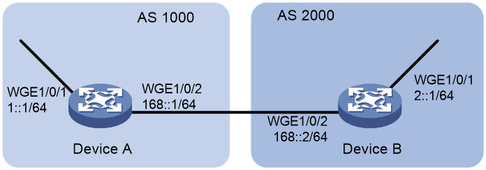
Procedure
1. Configure IPv6 addresses for each interface. (Details not shown.)
2. Configure BGP on Device A.
<DeviceA> system-view
[DeviceA] bgp 1000
[DeviceA] peer 168::2 as-number 2000
[DeviceA] peer 168::2 connect-interface twenty-fivegige 1/0/2
[DeviceA-bgp] address-family ipv6
[DeviceA-bgp-ipv6] peer 168::2 enable
[DeviceA-bgp-ipv6] import-route direct
[DeviceA-bgp-ipv6] quit
[DeviceA-bgp] quit
3. Configure Device B:
# Configure BGP.
<DeviceB> system-view
[DeviceB] bgp 2000
[DeviceB] peer 168::1 as-number 1000
[DeviceB] peer 168::1 connect-interface twenty-fivegige 1/0/2
[DeviceB-bgp] address-family ipv6
[DeviceB-bgp-ipv6] peer 168::1 enable
[DeviceB-bgp-ipv6] peer 168::1 route-policy qppb import
[DeviceB-bgp-ipv6] quit
[DeviceB-bgp] quit
# Configure a routing policy.
[DeviceB] route-policy qppb permit node 0
[DeviceB-route-policy-qppb-0] apply qos-local-id 4
[DeviceB-route-policy-qppb-0] quit
# Enable QPPB on Twenty-FiveGigE 1/0/2.
[DeviceB] interface twenty-fivegige 1/0/2
[DeviceB-Twenty-FiveGigE1/0/2] bgp-policy destinationip-qos-map
# Configure a QoS policy.
[DeviceB] traffic classifier qppb
[DeviceB-classifier-qppb] if-match qos-local-id 4
[DeviceB-classifier-qppb] quit
[DeviceB] traffic behavior qppb
[DeviceB-behavior-qppb] car cir 512000 red discard
[DeviceB-behavior-qppb] quit
[DeviceB] qos policy qppb
[DeviceB-qospolicy-qppb] classifier qppb behavior qppb mode qppb-manipulation
[DeviceB-qospolicy-qppb] quit
# Apply the QoS policy to the incoming traffic of Twenty-FiveGigE 1/0/1.
[DeviceB] interface twenty-fivegige 1/0/1
[DeviceB-Twenty-FiveGigE1/0/1] qos apply policy qppb inbound
[DeviceB-Twenty-FiveGigE1/0/1] quit
Verifying the configuration
# Verify that the related routes on Device A take effect.
[DeviceA] display bgp routing-table ipv6 2:: 64
BGP local router ID: 0.0.0.0
Local AS number: 1000
Paths: 1 available, 1 best
BGP routing table information of 168::/64:
Imported route.
Original nexthop: ::
Out interface : Twenty-FiveGigE 1/0/2
Route age : 00h17m18s
OutLabel : NULL
RxPathID : 0x0
TxPathID : 0x0
AS-path : (null)
Origin : incomplete
Attribute value : MED 0, pref-val 32768
State : valid, local, best
IP precedence : N/A
QoS local ID : N/A
Traffic index : N/A
Tunnel policy : NULL
Rely tunnel IDs : N/A
# Verify that the related routes on Device B take effect.
[DeviceB] display bgp routing-table ipv6 1:: 64
BGP local router ID: 0.0.0.0
Local AS number: 2000
Paths: 1 available, 1 best
BGP routing table information of 168::/64:
Imported route.
Original nexthop: ::
Out interface : Twenty-FiveGigE 1/0/2
Route age : 00h05m17s
OutLabel : NULL
RxPathID : 0x0
TxPathID : 0x0
AS-path : (null)
Origin : incomplete
Attribute value : MED 0, pref-val 32768
State : valid, local, best
IP precedence : N/A
QoS local ID : N/A
Traffic index : N/A
Tunnel policy : NULL
Rely tunnel IDs : N/A
# Display the configuration and statistics for the QoS policy applied to Twenty-FiveGigE 1/0/1 on Device C.
[DeviceC] display qos policy interface twenty-fivegige 1/0/1
Interface: Twenty-FiveGigE1/0/1
Direction: Inbound
Policy: qppb
Classifier: default-class
Mode: qppb-manipulation
Operator: AND
Rule(s) :
If-match any
Behavior: be
-none-
Classifier: qppb
Mode: qppb-manipulation
Operator: AND
Rule(s) :
If-match qos-local-id 4
Behavior: qppb
Committed Access Rate:
CIR 512000 (kbps), CBS 32000000 (Bytes), EBS 0 (Bytes)
Green action : pass
Yellow action : pass
Red action : discard
Green packets : 0 (Packets) 0 (Bytes)
Yellow packets: 0 (Packets) 0 (Bytes)
Red packets : 0 (Packets) 0 (Bytes)
Configuring packet-drop logging for control plane protocols
About packet-drop logging for control plane protocols
A device provides the user plane and the control plane.
· User plane—The units at the user plane are responsible for receiving, transmitting, and switching (forwarding) packets, such as various dedicated forwarding chips. They deliver super processing speeds and throughput.
· Control plane—The units at the control plane are processing units running most routing and switching protocols. They are responsible for protocol packet resolution and calculation, such as CPUs. Compared with user plane units, the control plane units allow for great packet processing flexibility but have lower throughput.
If protocol packets sent to the control plane are dropped, the protocol operation will be affected. You can configure control plane packet-drop logging. The device regularly generates and sends logs to the information center. For information about configuring the information center, see Network Management and Monitoring Configuration Guide.
Procedure
1. Enter system view.
system-view
2. Enable packet-drop logging for control plane protocols.
qos control-plane logging protocol { protocol-name&<1-8> | all } enable
By default, packet-drop logging is disabled for all control plane protocols.
3. (Optional.) Set the interval for sending packet-drop logs.
qos control-plane logging interval interval
The default setting is 5 seconds.
Appendixes
Appendix A Acronyms
Table 3 Appendix A Acronyms
|
Acronym |
Full spelling |
|
AF |
Assured Forwarding |
|
BE |
Best Effort |
|
BQ |
Bandwidth Queuing |
|
CAR |
Committed Access Rate |
|
CBS |
Committed Burst Size |
|
CBQ |
Class Based Queuing |
|
CE |
Congestion Experienced |
|
CIR |
Committed Information Rate |
|
CQ |
Custom Queuing |
|
DCBX |
Data Center Bridging Exchange Protocol |
|
DiffServ |
Differentiated Service |
|
DSCP |
Differentiated Services Code Point |
|
EBS |
Excess Burst Size |
|
ECN |
Explicit Congestion Notification |
|
EF |
Expedited Forwarding |
|
FIFO |
First in First out |
|
FQ |
Fair Queuing |
|
GMB |
Guaranteed Minimum Bandwidth |
|
GTS |
Generic Traffic Shaping |
|
INT |
Inband Network Telemetry |
|
IntServ |
Integrated Service |
|
ISP |
Internet Service Provider |
|
LLQ |
Low Latency Queuing |
|
LSP |
Label Switched Path |
|
MPLS |
Multiprotocol Label Switching |
|
PE |
Provider Edge |
|
PIR |
Peak Information Rate |
|
PQ |
Priority Queuing |
|
QoS |
Quality of Service |
|
QPPB |
QoS Policy Propagation Through the Border Gateway Protocol |
|
RED |
Random Early Detection |
|
RSVP |
Resource Reservation Protocol |
|
RTP |
Real-Time Transport Protocol |
|
SP |
Strict Priority |
|
ToS |
Type of Service |
|
VoIP |
Voice over IP |
|
VPN |
Virtual Private Network |
|
WFQ |
Weighted Fair Queuing |
|
WRED |
Weighted Random Early Detection |
|
WRR |
Weighted Round Robin |
Appendix B Default priority maps
For the default dot1p-exp, dscp-dscp, and exp-dot1p priority maps, an input value yields a target value equal to it.
Table 4 Default dot1p-lp and dot1p-dp priority maps
|
Input priority value |
dot1p-lp map |
dot1p-dp map |
|
dot1p |
lp |
dp |
|
0 |
2 |
0 |
|
1 |
0 |
0 |
|
2 |
1 |
0 |
|
3 |
3 |
0 |
|
4 |
4 |
0 |
|
5 |
5 |
0 |
|
6 |
6 |
0 |
|
7 |
7 |
0 |
Table 5 Default dscp-dp and dscp-dot1p priority maps
|
Input priority value |
dscp-dp map |
dscp-dot1p map |
|
dscp |
dp |
dot1p |
|
0 to 7 |
0 |
0 |
|
8 to 15 |
0 |
1 |
|
16 to 23 |
0 |
2 |
|
24 to 31 |
0 |
3 |
|
32 to 39 |
0 |
4 |
|
40 to 47 |
0 |
5 |
|
48 to 55 |
0 |
6 |
|
56 to 63 |
0 |
7 |
Table 6 Default port priority-local priority map
|
Port priority |
Local precedence |
|
0 |
0 |
|
1 |
1 |
|
2 |
2 |
|
3 |
3 |
|
4 |
4 |
|
5 |
5 |
|
6 |
6 |
|
7 |
7 |
Appendix C Introduction to packet precedence
IP precedence and DSCP values
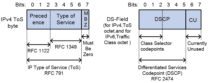
As shown in Figure 30, the ToS field in the IP header contains 8 bits. The first 3 bits (0 to 2) represent IP precedence from 0 to 7. According to RFC 2474, the ToS field is redefined as the differentiated services (DS) field. A DSCP value is represented by the first 6 bits (0 to 5) of the DS field and is in the range 0 to 63. The remaining 2 bits (6 and 7) are reserved.
Table 7 IP precedence
|
IP precedence (decimal) |
IP precedence (binary) |
Description |
|
0 |
000 |
Routine |
|
1 |
001 |
priority |
|
2 |
010 |
immediate |
|
3 |
011 |
flash |
|
4 |
100 |
flash-override |
|
5 |
101 |
critical |
|
6 |
110 |
internet |
|
7 |
111 |
network |
Table 8 DSCP values
|
DSCP value (decimal) |
DSCP value (binary) |
Description |
|
46 |
101110 |
ef |
|
10 |
001010 |
af11 |
|
12 |
001100 |
af12 |
|
14 |
001110 |
af13 |
|
18 |
010010 |
af21 |
|
20 |
010100 |
af22 |
|
22 |
010110 |
af23 |
|
26 |
011010 |
af31 |
|
28 |
011100 |
af32 |
|
30 |
011110 |
af33 |
|
34 |
100010 |
af41 |
|
36 |
100100 |
af42 |
|
38 |
100110 |
af43 |
|
8 |
001000 |
cs1 |
|
16 |
010000 |
cs2 |
|
24 |
011000 |
cs3 |
|
32 |
100000 |
cs4 |
|
40 |
101000 |
cs5 |
|
48 |
110000 |
cs6 |
|
56 |
111000 |
cs7 |
|
0 |
000000 |
be (default) |
802.1p priority
802.1p priority lies in the Layer 2 header. It applies to occasions where Layer 3 header analysis is not needed and QoS must be assured at Layer 2.
Figure 31 An Ethernet frame with an 802.1Q tag header
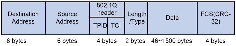
As shown in Figure 31, the 4-byte 802.1Q tag header contains the 2-byte tag protocol identifier (TPID) and the 2-byte tag control information (TCI). The value of the TPID is 0x8100. Figure 32 shows the format of the 802.1Q tag header. The Priority field in the 802.1Q tag header is called 802.1p priority, because its use is defined in IEEE 802.1p. Table 9 shows the values for 802.1p priority.
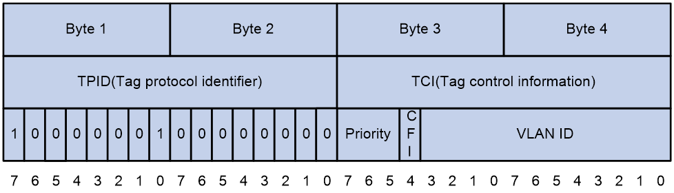
Table 9 Description on 802.1p priority
|
802.1p priority (decimal) |
802.1p priority (binary) |
Description |
|
0 |
000 |
best-effort |
|
1 |
001 |
background |
|
2 |
010 |
spare |
|
3 |
011 |
excellent-effort |
|
4 |
100 |
controlled-load |
|
5 |
101 |
video |
|
6 |
110 |
voice |
|
7 |
111 |
network-management |
EXP values
The EXP field is in MPLS labels for MPLS QoS purposes. As shown in Figure 33, the EXP field is 3-bit long and is in the range of 0 to 7.
Figure 33 MPLS label structure
![]()