- Table of Contents
-
- H3C S12500R Switch Router Series Installation Guide-6W102
- 00-Preface
- 01-Chapter 1 Preparing for Installation
- 02-Chapter 2 Installing the Device
- 03-Chapter 3 Installing FRUs
- 04-Chapter 4 Connecting Your Device to the Network
- 05-Chapter 5 Troubleshooting
- 06-Chapter 6 Replacement Procedures
- 07-Appendix A Engineering labels
- 08-Appendix B Cabling Recommendations
- 09-Appendix C Repackaging the Device
- Related Documents
-
| Title | Size | Download |
|---|---|---|
| 04-Chapter 4 Connecting Your Device to the Network | 906.49 KB |
4 Connecting your device to the network
Accessing the device for the first time
Setting up the configuration environment
Configuring authentication on a user interface
Configuring the basic access function
Verifying the network configuration
Connecting the device to the network
Connecting the device to the network through an optical fiber
4 Connecting your device to the network
This chapter describes how to connect your device to a network.
The first time you access the device you must log in through the console port. On the device, you can configure Telnet or SSH for remote access through Ethernet ports. You manage console login users at AUX user lines, and manage Telnet and SSH users at VTY user lines. For more information about login methods and user lines, see H3C S12500R Switch Router Series Fundamentals Configuration Guide.
|
|
NOTE: · The device supports one AUX user when it has one MPU installed and supports a maximum of two concurrent AUX users when it has two MPUs installed. · The device supports a maximum of 32 concurrent VTY users. |
Accessing the device for the first time
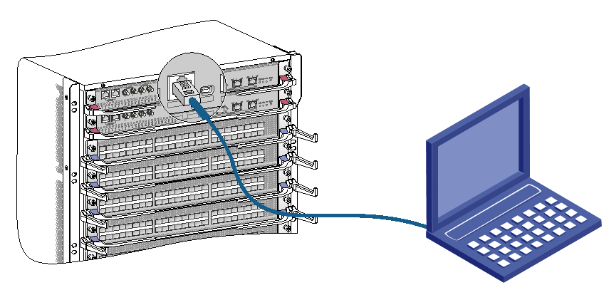
The first time you access the device you must use a console cable to connect a console terminal, for example, a PC, to the console port on the device.
Setting up the configuration environment
To connect a terminal (for example, a PC) to the device:
1. Plug the DB-9 female connector of the console cable to the serial port of the PC.
2. Plug the RJ-45 connector of the console cable to the console port of the device.
3. Power on the PC.
|
|
NOTE: · Identify the mark on the console port and make sure you are connecting to the correct port. · The serial ports on PCs do not support hot swapping. To connect a PC to an operating device, first connect the PC end. To disconnect a PC from an operating device, first disconnect the device end. |
Figure 4-1 Connecting a terminal to the device (S12516R)
Setting terminal parameters
To configure and manage the device through the console port, you must run a terminal emulator program, HyperTerminal or PuTTY, on your configuration terminal. You can use the emulator program to connect a network device, a Telnet site, or an SSH site. For more information about the terminal emulator programs, see the user guides for these programs.
The following are the required terminal settings:
· Bits per second—9600.
· Data bits—8.
· Stop bits—1.
· Parity—None.
· Flow control—None.
Powering on the device
Before powering on the device, confirm the following information:
· You know where the emergency power-off device for the equipment room is located.
· The device has been securely mounted.
· All the cards have been correctly installed.
· The unused slots have been installed with filler panels.
· All the network cables, fibers, power cords, and grounding cables have been correctly connected.
· The input power voltage meets the requirement of the device.
· The console cable is correctly connected, the terminal or PC used for configuration has started, and the configuration parameters have been set.
To power on the device, turn on the power source of the device.
The following is a sample output you can see on the terminal:
Press Ctrl+D to access BASIC-BOOTWARE MENU...
Press Ctrl+T to start memory test
Booting Normal Extended BootWare
The Extended BootWare is self-decompressing..........Done.
…
System image is starting...
Line aux0 is available.
Press ENTER to get started.
Press Enter at the prompt. When the prompt <Sysname> appears, you can configure the device.
After powering on the device, check the following items:
· The cooling system is working, and you can hear fan rotating noise and feel air being blown out.
· The system status LEDs on the MPUs show that the system is operating normally. For more information about LED behaviors, see H3C S12500R Switch Router Series Hardware Reference.
Configuring the device
By default, the device does not authenticate the console login user at an AUX interface. To increase system security and enable remote management:
· Configure remote access services, for example, Telnet or SSH.
· Configure authentication on each user interface, including the AUX interfaces.
Configuring authentication on a user interface
You can configure authentication on a user interface to control access to the device.
Table 4-1 describes the Telnet login authentication methods available for a VTY user line.
Table 4-1 Telnet login authentication methods
|
Authentication method |
Feature |
Application scenarios |
|
None |
Easy to configure, allows any user to Telnet to your device, and lowest in security |
Lab environments and extremely secure network environments |
|
Password |
Easy to configure, secure, and flat user management |
Environments that do not need granular privilege management |
|
Username and password |
Complex to configure, secure, and hierarchical user management |
Environments where multiple user roles cooperate to manage the device |
For more information about login methods, see H3C S12500R Switch Router Series Fundamentals Configuration Guide.
Configuring the basic access function
The device without any configuration can perform basic data forwarding immediately after it is connected to a network. To implement more forwarding features, configure the basic network settings in Table 4-2 on the device.
Table 4-2 Basic network settings
|
Setting |
Description |
|
IP address |
Enables remote device management, for example, by using Telnet. |
|
Static routes |
Implement static routing. |
|
VLANs |
Divide the LAN into multiple VLANs for data security. |
|
MSTP |
Avoids loops in a dual-homed network. |
Configuration example
Configuring Telnet service
# Enter system view.
<Sysname> system-view
# Enable the Telnet server.
[Sysname] telnet server enable
# Enter the view of user line VTY 0.
[Sysname] user-interface vty 0
# Enable password authentication on the user line.
[Sysname-line-vty0] authentication-mode password
# Set the password to hello in plaintext.
[Sysname-line-vty0] set authentication password simple hello
# Assign user role network-admin through the user line VTY 0.
[Sysname-line-vty0] user-role network-admin
[Sysname-line-vty0] quit
Configuring the basic network settings
· Configure IP addresses
# Create VLAN-interface 1.
[Sysname] interface vlan-interface 1
# Assign an IP address, for example, 192.168.0.1, to VLAN-interface 1.
[Sysname-Vlan-interface1] ip address 192.168.0.1 24
[Sysname-Vlan-interface1] quit
· Configure static routes
# Configure a static route, with the destination IP address 172.16.1.0 and the next hop IP address 192.168.0.2.
[Sysname] ip route-static 172.16.1.0 255.255.255.0 192.168.0.2
· Configure VLANs
# Create VLAN 10 and enter its view.
[Sysname] vlan 10
[Sysname-vlan10]
# Assign port Ten-GigabitEthernet 1/0/1 to VLAN 10.
[Sysname-vlan10] port ten-gigabitethernet 1/0/1
[Sysname-vlan10] quit
· Configure MSTP
# Create an MST region named example, map VLAN 10 to instance 1, and set the MSTP revision level to 0.
[Sysname] stp region-configuration
[Sysname-mst-region] region-name example
[Sysname-mst-region] instance 1 vlan 10
[Sysname-mst-region] revision-level 0
# Activate the MST region configuration.
[Sysname-mst-region] active region-configuration
[Sysname-mst-region] quit
# Configure the device as the primary root bridge of instance 1.
[Sysname] stp instance 1 root primary
# Enable MSTP globally.
[Sysname] stp global enable
For more information about these features, see H3C S12500R Switch Router Series Configuration Guides.
Verifying the network configuration
To verify the software version and network configuration, execute display commands in any view.
|
Task |
Command |
|
Display the name, model, and system software version of the device |
display version |
|
Display the current configuration of the device |
display current-configuration |
|
Display the interface status and configuration |
display interface brief |
|
Display the IP configuration of Layer 3 interfaces |
display ip interface brief |
|
Display brief information about active routes in the routing table |
display ip routing-table |
|
Display VLAN settings |
display vlan |
|
Display the spanning tree status and statistics |
display stp brief |
Connecting the device to the network
|
|
WARNING! To avoid injury to your eyes, do not stare at the fiber ports and optical fiber connectors when connecting optical fibers. |
Before you connect the device to the network, verify that all its basic network settings are correct.
Connecting the device to the network through an optical fiber
You can install a transceiver module (see "Installing FRUs") in a fiber port and use an optical fiber to connect the port to the network. For more information about optical fibers, see H3C S12500R Switch Router Series Hardware Reference.
To connect a fiber port to a peer device through an optical fiber:
1. Install a transceiver module into the port.
2. Remove the dust cover of the optical fiber connector, and clean the end of the optical fiber.
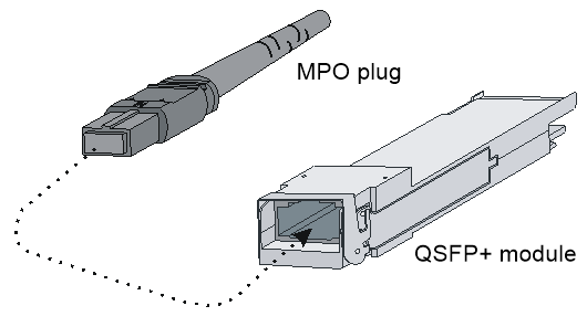
3. Remove the dust plug of the transceiver module, plug one end of the optical fiber into the transceiver module, and plug the other end into the transceiver module in the peer device.
¡ For information about how to connect an LC connector, see Figure 4-2.
¡ For information about how to connect an MPO connector, see Figure 4-3.
Figure 4-2 Using an LC optical fiber connector to connect an SFP module
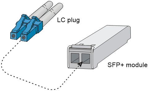
Figure 4-3 Using an MPO optical fiber connector to connect a QSFP module
4. Examine the port LEDs for incorrect connection.
For more information about the LED status, see H3C S12500R Switch Router Series Hardware Reference.
|
|
NOTE: For the QSFP+/QSFP28/CXP module, you do not need to differentiate between the transmitter (TX) and receiver (RX) ports. For other types of transceiver modules, the TX port on one end must connect to the RX port on the other end. |
Testing connectivity
After you connect the device to the network, use the ping or tracert command to test the network connectivity. For more information about these commands, see H3C S12500R Switch Router Series Command References.
