- Table of Contents
- Related Documents
-
| Title | Size | Download |
|---|---|---|
| 05-MOD configuration | 75.89 KB |
Configuring MOD
Overview
Mirror On Drop (MOD) can detect packet drops during the forwarding process on the device. When a packet is dropped, MOD can send the packet drop reason and the characteristics of the dropped packet to the collector.
MOD uses the flow entries generated based on a flow group to detect dropped packets. For more information about flow groups, see flow group configuration in Telemetry Configuration Guide.
MOD works as follows:
1. The device generates flow entries based on a flow group.
2. Based on the packet drop reason list of MOD, the device monitors packet drops for packets matching the flow entries.
3. If a packet is dropped for a reason on the packet drop reason list, the device sends the packet drop reason and the characteristics of the dropped packet (flow entry matching the packet) to the collector.
Restrictions and guidelines: MOD configuration
MOD takes effect only on packets matching flow groups.
MOD monitors only packets dropped for reasons on the configured packet drop reason list. MOD does not monitor packets dropped for other reasons.
Procedure
1. Enter system view.
system-view
2. Enter MOD view.
telemetry mod
3. Configure the device ID for MOD.
device-id address
By default, no device ID is configured for MOD.
4. Configure the encapsulation information for packets sent to the collector by MOD.
collector source-ip source-address destination-ip destination-address source-port source-port destination-port destination-port [ vlan vlan-id ]
By default, the encapsulation information for packets sent to the collector by MOD is not configured.
5. Configure the packet drop reason list monitored by MOD.
reason-list { reason-list | all }
By default, no packet drop reasons is configured, and the device does not monitor packet drops.
For more information about the packet drop reason list, see the reason-list command in Telemetry Command Reference.
Verifying and maintaining MOD
To verify the MOD configuration, execute the following command in any view:
display telemetry mod [ slot slot-number ]
MOD configuration examples
Example: Configuring MOD to send packets through UDP
Network configuration
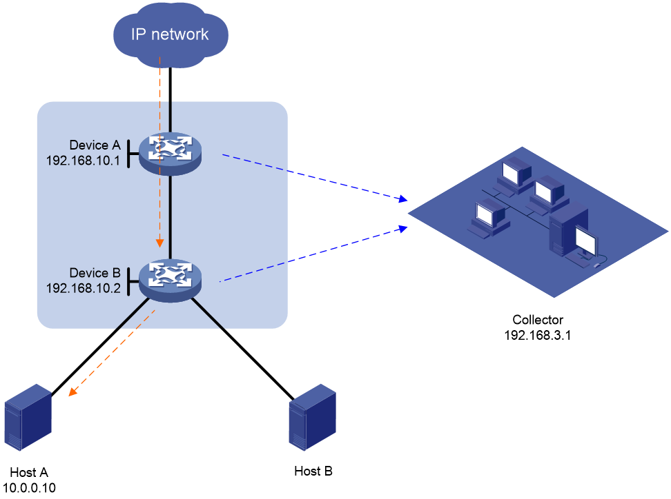
As shown in Figure 1, Host A and Host B access the external network through Device A and Device B. Some packets from the external network are missing on Host A. Configure MOD on the access device and aggregation device to identify whether packets are dropped during the forwarding process on the two devices.
Prerequisites
By default, interfaces on the device are disabled (in ADM or Administratively Down state). To have an interface operate, you must use the undo shutdown command to enable that interface.
Configure IP addresses for devices, and make sure they can reach each other at Layer 3.
Procedures
1. Configure Device A:
a. Configure a flow group:
# Set the flow entry aging time to 10 minutes.
<DeviceA> system-view
[DeviceA] telemetry flow-group aging-time 10
# Apply the system-defined IP flow group.
[DeviceA] telemetry apply flow-group system-defined ip
b. Configure MOD:
# Configure the device ID for MOD as 192.168.10.1.
[DeviceA] telemetry mod
[DeviceA-telemetry-mod] device-id 192.168.10.1
[DeviceA-telemetry-mod] quit
# Encapsulate the packets sent to the collector by MOD with the following information: source IP address 192.168.10.1, destination IP address 192.168.3.1, source port number 1000, and destination port number 2333.
[DeviceA-telemetry-mod] collector source-ip 192.168.10.1 destination-ip 192.168.3.1 source-port 1000 destination-port 2333
# Configure MOD to monitor all packet drop reasons.
[DeviceA-telemetry-mod] reason-list all
[DeviceA-telemetry-mod] quit
2. Configure Device B.
Configure Device B in the same way Device A is configured except the device ID for MOD and the source IP address encapsulated in the packets sent to the collector.
Verifying the configuration
1. Verify the configuration on Device A:
# Display the flow group configuration.
<DeviceA> display telemetry flow-group system-defined ip
Flow group named system-defined-ip (Successful)
Template :
destination-ip
destination-port
protocol
source-ip
source-port
Aging time: 10 minutes
# Display the MOD configuration.
<DeviceA> display telemetry mod
Drop reason list:
ipv4-dip-miss
smac-equal-dmac
denied-vlan
Device ID : 192.168.10.1
Transport protocol : udp
Collector
Source IP : 192.168.10.1
Destination IP : 192.168.3.1
Source port : 1000
Destination port : 2333
2. Verify the configuration on Device B.
The configuration on Device B is the same as the configuration on Device A except the device ID for MOD and the source IP address encapsulated in the packets sent to the collector. (Details not shown.)
3. Verify the configuration on the collector.
When a packet destined for IP address 10.0.0.10 is dropped during the forwarding process on Device A and Device B, the collector can receive the packet drop reason and the characteristics of the dropped packet from the devices.
