- Table of Contents
-
- 16-Network Management and Monitoring Configuration Guide
- 00-Preface
- 01-Ping and tracert configuration
- 02-System debugging configuration
- 03-NQA configuration
- 04-NTP configuration
- 05-SNMP configuration
- 06-RMON configuration
- 07-Event MIB configuration
- 08-Sampler configuration
- 09-Mirroring configuration
- 10-NetStream configuration
- 11-IPv6 NetStream configuration
- 12-sFlow configuration
- 13-CWMP configuration
- 14-PTP configuration
- Related Documents
-
| Title | Size | Download |
|---|---|---|
| 03-NQA configuration | 346.77 KB |
Restrictions and guidelines: NQA configuration
Enabling and configuring the NQA server
Displaying the NQA server status
Configuring NQA operations on the NQA client
NQA operations tasks at a glance
Configuring the ICMP echo operation
Configuring the DHCP operation
Configuring the HTTP operation
Configuring the SNMP operation
Configuring the UDP echo operation
Configuring the UDP tracert operation
Configuring the DLSw operation
Configuring optional parameters for the NQA operation
Configuring the collaboration feature
Configuring threshold monitoring
Configuring the NQA statistics collection feature
Configuring the saving of NQA history records
Scheduling the NQA operation on the NQA client
Example: Configuring the ICMP echo operation
Example: Configuring the DHCP operation
Example: Configuring the DNS operation
Example: Configuring the FTP operation
Example: Configuring the HTTP operation
Example: Configuring the SNMP operation
Example: Configuring the TCP operation
Example: Configuring the UDP echo operation
Example: Configuring the UDP tracert operation
Example: Configuring the DLSw operation
Example: Configuring NQA collaboration
Configuring NQA
About NQA
Network quality analyzer (NQA) allows you to measure network performance, verify the service levels for IP services and applications, and troubleshoot network problems.
NQA operating mechanism
An NQA operation contains a set of parameters such as the operation type, destination IP address, and port number to define how the operation is performed. Each NQA operation is identified by the combination of the administrator name and the operation tag. You can configure the NQA client to run the operations at scheduled time periods.
As shown in Figure 1, the NQA source device (NQA client) sends data to the NQA destination device by simulating IP services and applications to measure network performance.
All types of NQA operations require the NQA client, but only the TCP and UDP echo operations require the NQA server. The NQA operations for services that are already provided by the destination device such as FTP do not need the NQA server. You can configure the NQA server to listen and respond to specific IP addresses and ports to meet various test needs.

After starting an NQA operation, the NQA client periodically performs the operation at the interval specified by using the frequency command.
You can set the number of probes the NQA client performs in an operation by using the probe count command.
Collaboration with Track
NQA can collaborate with the Track module to notify application modules of state or performance changes so that the application modules can take predefined actions.
The NQA + Track collaboration is available for the following application modules:
· VRRP.
· Static routing.
· Policy-based routing.
· Smart Link.
The following describes how a static route destined for 192.168.0.88 is monitored through collaboration:
1. NQA monitors the reachability to 192.168.0.88.
2. When 192.168.0.88 becomes unreachable, NQA notifies the Track module of the change.
3. The Track module notifies the static routing module of the state change.
4. The static routing module sets the static route to invalid according to a predefined action.
For more information about collaboration, see High Availability Configuration Guide.
Threshold monitoring
Threshold monitoring enables the NQA client to take a predefined action when the NQA operation performance metrics violate the specified thresholds.
Table 1 describes the relationships between performance metrics and NQA operation types.
Table 1 Performance metrics and NQA operation types
|
Performance metric |
NQA operation types that can gather the metric |
|
Probe duration |
ICMP echo, DHCP, DNS, FTP, HTTP, SNMP, TCP, UDP echo, and DLSw |
|
Number of probe failures |
ICMP echo, DHCP, DNS, FTP, HTTP, SNMP, TCP, UDP echo, and DLSw |
Restrictions and guidelines: NQA configuration
To avoid failures, follow these restrictions to configure the listening ports on the NQA client and the NQA server:
· Do not use a well-known port.
· Do not use a port in use by other services on this device.
¡ Use display tcp and display udp to display the IPv4 address and the port number in use on this device.
¡ Use display ipv6 tcp and display ipv6 udp to display the IPv6 address and the port number in use on this device.
The destination port set on the NQA client must be the same as the port listened by the server.
NQA tasks at a glance
To configure NQA, perform the following tasks:
Perform this task on the destination device before you configure the TCP and UDP echo operations.
3. Configuring NQA operations on the NQA client
After you configure an NQA operation, you can schedule the NQA client to run the NQA operation.
Configuring the NQA server
Restrictions and guidelines
To perform TCP and UDP echo operations, you must configure the NQA server on the destination device.
The NQA server listens and responds to requests on the specified IP addresses and ports.
You can configure multiple TCP or UDP listening services on an NQA server, where each corresponds to a specific IP address and port number.
The IP address, port number, and VPN instance for a listening service must be unique on the NQA server and match the configuration on the NQA client.
Enabling and configuring the NQA server
1. Enter system view.
system-view
2. Enable the NQA server.
nqa server enable
By default, the NQA server is disabled.
3. Configure a TCP listening service.
nqa server tcp-connect ip-address port-number [ vpn-instance vpn-instance-name ] [ tos tos ]
This task is required for TCP and DLSw operations. For the DLSw operation, the port number for the TCP listening service must be 2065.
4. Configure a UDP listening service.
nqa server udp-echo ip-address port-number [ vpn-instance vpn-instance-name ] [ tos tos ]
This task is required for only UDP echo operations.
Displaying the NQA server status
To display the NQA server status, execute the following command in any view:
display nqa server
Enabling the NQA client
1. Enter system view.
system-view
2. Enable the NQA client.
nqa agent enable
By default, the NQA client is enabled.
The NQA client configuration takes effect after you enable the NQA client.
Configuring NQA operations on the NQA client
NQA operations tasks at a glance
To configure NQA operations, perform the following tasks:
1. Configuring an NQA operation
¡ Configuring the ICMP echo operation
¡ Configuring the DHCP operation
¡ Configuring the DNS operation
¡ Configuring the FTP operation
¡ Configuring the HTTP operation
¡ Configuring the SNMP operation
¡ Configuring the TCP operation
¡ Configuring the UDP echo operation
¡ Configuring the UDP tracert operation
¡ Configuring the DLSw operation
2. (Optional.) Configuring optional parameters for the NQA operation
3. (Optional.) Configuring the collaboration feature
4. (Optional.) Configuring threshold monitoring
5. (Optional.) Configuring the NQA statistics collection feature
6. (Optional.) Configuring the saving of NQA history records
7. Scheduling the NQA operation on the NQA client
Configuring the ICMP echo operation
About this task
The ICMP echo operation measures the reachability of a destination device. It has the same function as the ping command, but provides more output information. In addition, if multiple paths exist between the source and destination devices, you can specify the next hop for the ICMP echo operation.
The ICMP echo operation sends an ICMP echo request to the destination device per probe.
Procedure
1. Enter system view.
system-view
2. Create an NQA operation and enter NQA operation view.
nqa entry admin-name operation-tag
3. Specify the ICMP echo type and enter its view.
type icmp-echo
4. Specify the destination IP address for ICMP echo requests.
destination ip ip-address
By default, no destination IP address is specified.
5. Specify the source address for ICMP echo requests. Choose one option as needed:
¡ Use the IP address of the specified interface as the source IP address.
source interface interface-type interface-number
By default, the source IP address of ICMP echo requests is the primary IP address of their output interface.
The specified source interface must be up.
¡ Specify the source IPv4 address.
source ip ip-address
By default, the source IPv4 address of ICMP echo requests is the primary IPv4 address of their output interface.
The specified source IPv4 address must be the IPv4 address of a local interface, and the interface must be up. Otherwise, no probe packets can be sent out.
6. Specify the output interface or the next hop IP address for ICMP echo requests. Choose one option as needed:
¡ Specify the output interface.
out interface interface-type interface-number
By default, the output interface is not specified. The NQA client determines the output interface based on the routing table lookup.
¡ Specify the next hop IPv4 address.
next-hop ip ip-address
By default, no next hop IPv4 address is specified.
7. (Optional.) Set the payload size for each ICMP echo request.
data-size size
The default payload size is 100 bytes.
8. (Optional.) Specify the payload fill string for ICMP echo requests.
data-fill string
The default payload fill string is the hexadecimal string 00010203040506070809.
Configuring the DHCP operation
About this task
The DHCP operation measures whether or not the DHCP server can respond to client requests. DHCP also measures the amount of time it takes the NQA client to obtain an IP address from a DHCP server.
The NQA client simulates the DHCP relay agent to forward DHCP requests for IP address acquisition from the DHCP server. The interface that performs the DHCP operation does not change its IP address. When the DHCP operation completes, the NQA client sends a packet to release the obtained IP address.
The DHCP operation acquires an IP address from the DHCP server per probe.
Procedure
1. Enter system view.
system-view
2. Create an NQA operation and enter NQA operation view.
nqa entry admin-name operation-tag
3. Specify the DHCP type and enter its view.
type dhcp
4. Specify the IP address of the DHCP server as the destination IP address of DHCP packets.
destination ip ip-address
By default, no destination IP address is specified.
5. Specify the output interface for DHCP request packets.
out interface interface-type interface-number
By default, the NQA client determines the output interface based on the routing table lookup.
6. Specify the source IP address of DHCP request packets.
source ip ip-address
By default, the source IP address of DHCP request packets is the primary IP address of their output interface.
The specified source IP address must be the IP address of a local interface, and the local interface must be up. Otherwise, no probe packets can be sent out.
Configuring the DNS operation
About this task
The DNS operation simulates domain name resolution, and it measures the time for the NQA client to resolve a domain name into an IP address through a DNS server. The obtained DNS entry is not saved.
The DNS operation resolves a domain name into an IP address per probe.
Procedure
1. Enter system view.
system-view
2. Create an NQA operation and enter NQA operation view.
nqa entry admin-name operation-tag
3. Specify the DNS type and enter its view.
type dns
4. Specify the IP address of the DNS server as the destination IP address of DNS packets.
destination ip ip-address
By default, no destination IP address is specified.
5. Specify the domain name to be translated.
resolve-target domain-name
By default, no domain name is specified.
Configuring the FTP operation
About this task
The FTP operation measures the time for the NQA client to transfer a file to or download a file from an FTP server.
The FTP operation uploads or downloads a file from an FTP server per probe.
Restrictions and guidelines
To upload (put) a file to the FTP server, use the filename command to specify the name of the file you want to upload. The file must exist on the NQA client.
To download (get) a file from the FTP server, include the name of the file you want to download in the url command. The file must exist on the FTP server. The NQA client does not save the file obtained from the FTP server.
Use a small file for the FTP operation. A big file might result in transfer failure because of timeout, or might affect other services because of the amount of network bandwidth it occupies.
Procedure
1. Enter system view.
system-view
2. Create an NQA operation and enter NQA operation view.
nqa entry admin-name operation-tag
3. Specify the FTP type and enter its view.
type ftp
4. Specify an FTP login username.
username username
By default, no FTP login username is specified.
5. Specify an FTP login password.
password { cipher | simple } string
By default, no FTP login password is specified.
6. Specify the source IP address for FTP request packets.
source ip ip-address
By default, the source IP address of FTP request packets is the primary IP address of their output interface.
The source IP address must be the IP address of a local interface, and the interface must be up. Otherwise, no FTP requests can be sent out.
7. Set the data transmission mode.
mode { active | passive }
The default mode is active.
8. Specify the FTP operation type.
operation { get | put }
The default FTP operation type is get.
9. Specify the destination URL for the FTP operation.
url url
By default, no destination URL is specified for an FTP operation.
Enter the URL in one of the following formats:
¡ ftp://host/filename.
¡ ftp://host:port/filename.
The filename argument is required only for the get operation.
10. Specify the name of the file to be uploaded.
filename file-name
By default, no file is specified.
This step is required only for the put operation.
The configuration does not take effect for the get operation.
Configuring the HTTP operation
About this task
The HTTP operation measures the time for the NQA client to obtain responses from an HTTP server.
The HTTP operation supports the following operation types:
· Get—Retrieves data such as a Web page from the HTTP server.
· Post—Sends data to the HTTP server for processing.
· Raw—Sends a user-defined HTTP request to the HTTP server. You must manually configure the content of the HTTP request to be sent.
The HTTP operation completes the operation of the specified type per probe.
Procedure
1. Enter system view.
system-view
2. Create an NQA operation and enter NQA operation view.
nqa entry admin-name operation-tag
3. Specify the HTTP type and enter its view.
type http
4. Specify the destination URL for the HTTP operation.
url url
By default, no destination URL is specified for an HTTP operation.
Enter the URL in one of the following formats:
¡ http://host/resource
¡ http://host:port/resource
5. Specify an HTTP login username.
username username
By default, no HTTP login username is specified.
6. Specify an HTTP login password.
password { cipher | simple } string
By default, no HTTP login password is specified.
7. Specify the HTTP version.
version { v1.0 | v1.1 }
By default, HTTP 1.0 is used.
8. Specify the HTTP operation type.
operation { get | post | raw }
The default HTTP operation type is get.
If you set the operation type to raw, the client pads the content configured in raw request view to the HTTP request to send to the HTTP server.
9. Configure the HTTP raw request.
a. Enter raw request view.
raw-request
Every time you enter raw request view, the previously configured raw request content is cleared.
b. Enter or paste the request content.
By default, no request content is configured.
For successful HTTP operations, make sure the raw request content is valid and does not contain command aliases configured by using the alias command. For more information about the alias command, see CLI commands in Fundamentals Command Reference.
c. Save the input and return to HTTP operation view.
quit
This step is required only when the operation type is set to raw.
10. Specify the source IP address for the HTTP packets.
source ip ip-address
By default, the source IP address of HTTP packets is the primary IP address of their output interface.
The source IP address must be the IP address of a local interface, and the interface must be up. Otherwise, no HTTP packets can be sent out.
Configuring the SNMP operation
About this task
The SNMP operation tests whether the SNMP service is available on an SNMP agent.
The SNMP operation sends one SNMPv1 packet, one SNMPv2c packet, and one SNMPv3 packet to the SNMP agent per probe.
Procedure
1. Enter system view.
system-view
2. Create an NQA operation and enter NQA operation view.
nqa entry admin-name operation-tag
3. Specify the SNMP type and enter its view.
type snmp
4. Specify the destination IP address for SNMP packets.
destination ip ip-address
By default, no destination IP address is specified.
5. Specify the destination port number for SNMP packets.
destination port port-number
The default destination port number of SNMP packets is 161.
6. Specify the source IP address for SNMP packets.
source ip ip-address
By default, the source IP address of SNMP packets is the primary IP address of their output interface.
The source IP address must be the IP address of a local interface, and the interface must be up. Otherwise, no SNMP packets can be sent out.
7. Specify the source port number for SNMP packets.
source port port-number
By default, the NQA client randomly picks an unused port as the source port when the operation starts.
For the operation to succeed, make sure the specified port number is not used by any services on the device. As a best practice, use the default value.
8. Specify the community name carried in the SNMPv1 and SNMPv2c packets.
community read { cipher | simple } community-name
By default, the SNMPv1 and SNMPv2c packets carry community name public.
Make sure the specified community name is the same as the community name configured on the SNMP agent.
Configuring the TCP operation
About this task
The TCP operation measures the time for the NQA client to establish a TCP connection to a port on the NQA server.
The TCP operation requires both the NQA server and the NQA client. Before you perform a TCP operation, configure a TCP listening service on the NQA server. For more information about the TCP listening service configuration, see "Configuring the NQA server."
The TCP operation sets up a TCP connection per probe.
Procedure
1. Enter system view.
system-view
2. Create an NQA operation and enter NQA operation view.
nqa entry admin-name operation-tag
3. Specify the TCP type and enter its view.
type tcp
4. Specify the destination address for TCP packets.
destination ip ip-address
By default, no destination IP address is specified.
The destination address must be the same as the IP address of the TCP listening service (configured by using the nqa server tcp-connect command) on the NQA server.
5. Specify the destination port number for TCP packets.
destination port port-number
By default, no destination port number is configured.
The destination port number must be the same as the port number of the TCP listening service (configured by using the nqa server tcp-connect command) on the NQA server.
6. Specify the source IP address for TCP packets.
source ip ip-address
By default, the source IPv4 address of TCP packets is the primary IPv4 address of their output interface.
The source IPv4 address must be the IPv4 address of a local interface, and the interface must be up. Otherwise, no TCP packets can be sent out.
Configuring the UDP echo operation
About this task
The UDP echo operation measures the round-trip time between the client and a UDP port on the NQA server.
The UDP echo operation requires both the NQA server and the NQA client. Before you perform a UDP echo operation, configure a UDP listening service on the NQA server. For more information about the UDP listening service configuration, see "Configuring the NQA server."
The UDP echo operation sends a UDP packet to the destination device per probe.
Procedure
1. Enter system view.
system-view
2. Create an NQA operation and enter NQA operation view.
nqa entry admin-name operation-tag
3. Specify the UDP echo type and enter its view.
type udp-echo
4. Specify the destination address for UDP packets.
destination ip ip-address
By default, no destination IP address is specified.
The destination address must be the same as the IP address of the UDP listening service (configured by using the nqa server udp-echo command) on the NQA server.
5. Specify the destination port number for UDP packets.
destination port port-number
By default, no destination port number is specified.
The destination port number must be the same as the port number of the UDP listening service (configured by using the nqa server udp-echo command) on the NQA server.
6. Specify the source IP address for UDP packets.
source ip ip-address
By default, the source IPv4 address of UDP packets is the primary IPv4 address of their output interface.
The source IPv4 address must be the IPv4 address of a local interface, and the interface must be up. Otherwise, no UDP packets can be sent out.
7. Specify the source port number for UDP packets.
source port port-number
By default, the NQA client randomly picks an unused port as the source port when the operation starts.
For the operation to succeed, make sure the specified port number is not used by any services on the device. As a best practice, use the default value.
8. (Optional.) Set the payload size for each UDP packet.
data-size size
The default setting is 100 bytes.
9. (Optional.) Specify the payload fill string for UDP packets.
data-fill string
The default payload fill string is the hexadecimal string 00010203040506070809.
Configuring the UDP tracert operation
About this task
The UDP tracert operation determines the routing path from the source device to the destination device.
The UDP tracert operation sends a UDP packet to a hop along the path per probe.
Restrictions and guidelines
The UDP tracert operation is not supported on IPv6 networks. To determine the routing path that the IPv6 packets traverse from the source to the destination, use the tracert ipv6 command. For more information about the command, see Network Management and Monitoring Command Reference.
Prerequisites
Before you configure the UDP tracert operation, you must perform the following tasks:
· Enable sending ICMP time exceeded messages on the intermediate devices between the source and destination devices. If the intermediate devices are H3C devices, use the ip ttl-expires enable command.
· Enable sending ICMP destination unreachable messages on the destination device. If the destination device is an H3C device, use the ip unreachables enable command.
For more information about the ip ttl-expires enable and ip unreachables enable commands, see Layer 3—IP Services Command Reference.
Procedure
1. Enter system view.
system-view
2. Create an NQA operation and enter NQA operation view.
nqa entry admin-name operation-tag
3. Specify the UDP tracert operation type and enter its view.
type udp-tracert
4. Specify the destination device for the operation. Choose one option as needed:
¡ Specify the destination device by its host name.
destination host host-name
By default, no destination host name is specified.
¡ Specify the destination device by its IP address.
destination ip ip-address
By default, no destination IP address is specified.
5. Specify the destination port number for UDP packets.
destination port port-number
By default, the destination port number is 33434.
This port number must be an unused number on the destination device, so that the destination device can reply with ICMP port unreachable messages.
6. Specify an output interface for UDP packets.
out interface interface-type interface-number
By default, the NQA client determines the output interface based on the routing table lookup.
7. Specify the source IP address for UDP packets.
¡ Specify the IP address of the specified interface as the source IP address.
source interface interface-type interface-number
By default, the source IP address of UDP packets is the primary IP address of their output interface.
Do not use an occupied port as the source port, otherwise the probe will fail. Use the default value.
¡ Specify the source IP address.
source ip ip-address
The specified source interface must be up. The source IP address must be the IP address of a local interface, and the local interface must be up. Otherwise, no probe packets can be sent out.
8. Specify the source port number for UDP packets.
source port port-number
By default, the NQA client randomly picks an unused port as the source port when the operation starts.
For the operation to succeed, make sure the specified port number is not used by any services on the device. As a best practice, use the default value.
9. Set the maximum number of consecutive probe failures.
max-failure times
The default setting is 5.
10. Set the initial TTL value for UDP packets.
init-ttl value
The default setting is 1.
11. (Optional.) Set the payload size for each UDP packet.
data-size size
The default setting is 100 bytes.
12. (Optional.) Enable the no-fragmentation feature.
no-fragment enable
By default, the no-fragmentation feature is disabled.
Configuring the DLSw operation
About this task
The DLSw operation measures the response time of a DLSw device.
It sets up a DLSw connection to the DLSw device per probe.
Restrictions and guidelines
For the DLSw operation to succeed, configure the nqa server tcp-connect command on the NQA server and make sure the port number for the TCP listening service is 2065.
Procedure
1. Enter system view.
system-view
2. Create an NQA operation and enter NQA operation view.
nqa entry admin-name operation-tag
3. Specify the DLSw type and enter its view.
type dlsw
4. Specify the destination IP address for the probe packets.
destination ip ip-address
By default, no destination IP address is specified.
5. Specify the source IP address for the probe packets.
source ip ip-address
By default, the source IP address of the probe packets is the primary IP address of their output interface.
The source IP address must be the IP address of a local interface, and the interface must be up. Otherwise, no probe packets can be sent out.
Configuring optional parameters for the NQA operation
Restrictions and guidelines
Unless otherwise specified, the following optional parameters apply to all types of NQA operations.
The parameter settings take effect only on the current operation.
Procedure
1. Enter system view.
system-view
2. Enter the view of an existing NQA operation.
nqa entry admin-name operation-tag
3. Configure a description for the operation.
description text
By default, no description is configured.
4. Set the interval at which the NQA operation repeats.
frequency interval
The default setting is 0 milliseconds, and only one operation is performed.
If the operation is not completed when the interval expires, the next operation does not start.
5. Specify the probe times.
probe count times
In an UDP tracert operation, the NQA client performs three probes to each hop to the destination by default.
In other types of operations, the NQA client performs one probe to the destination per operation by default.
6. Set the probe timeout time.
probe timeout timeout
The default setting is 3000 milliseconds.
7. Set the maximum number of hops that the probe packets can traverse.
ttl value
By default, the maximum number of hops is 30 for probe packets of the UDP tracert operation, and is 20 for probe packets of other types of operations.
This command is not available for the DHCP operations.
8. Set the ToS value in the IP header of the probe packets.
tos value
The default setting is 0.
9. Enable the routing table bypass feature.
route-option bypass-route
By default, the routing table bypass feature is disabled.
This command is not available for the DHCP operations.
This command does not take effect if the destination address of the NQA operation is an IPv6 address.
10. Specify the VPN instance where the operation is performed.
vpn-instance vpn-instance-name
By default, the operation is performed on the public network.
Configuring the collaboration feature
About this task
Collaboration is implemented by associating a reaction entry of an NQA operation with a track entry. The reaction entry monitors the NQA operation. If the number of operation failures reaches the specified threshold, the configured action is triggered.
Restrictions and guidelines
The UDP tracert operation does not support the collaboration feature.
A reaction entry cannot be modified after it is created.
Procedure
1. Enter system view.
system-view
2. Enter the view of an existing NQA operation.
nqa entry admin-name operation-tag
3. Configure a reaction entry.
reaction item-number checked-element probe-fail threshold-type consecutive consecutive-occurrences action-type trigger-only
You cannot modify the content of an existing reaction entry.
4. Return to system view.
quit
5. Associate Track with NQA.
For information about the configuration, see High Availability Configuration Guide.
6. Associate Track with an application module.
For information about the configuration, see High Availability Configuration Guide.
Configuring threshold monitoring
About this task
This feature allows you to monitor the NQA operation running status.
An NQA operation supports the following threshold types:
· average—If the average value for the monitored performance metric either exceeds the upper threshold or goes below the lower threshold, a threshold violation occurs.
· accumulate—If the total number of times that the monitored performance metric is out of the specified value range reaches or exceeds the specified threshold, a threshold violation occurs.
· consecutive—If the number of consecutive times that the monitored performance metric is out of the specified value range reaches or exceeds the specified threshold, a threshold violation occurs.
Threshold violations for the average or accumulate threshold type are determined on a per NQA operation basis. The threshold violations for the consecutive type are determined from the time the NQA operation starts.
The following actions might be triggered:
· none—NQA displays results only on the terminal screen. It does not send traps to the NMS.
· trap-only—NQA displays results on the terminal screen, and meanwhile it sends traps to the NMS.
To send traps to the NMS, the NMS address must be specified by using the snmp-agent target-host command. For more information about the command, see "SNMP commands."
· trigger-only—NQA displays results on the terminal screen, and meanwhile triggers other modules for collaboration.
In a reaction entry, configure a monitored element, a threshold type, and an action to be triggered to implement threshold monitoring.
The state of a reaction entry can be invalid, over-threshold, or below-threshold.
· Before an NQA operation starts, the reaction entry is in invalid state.
· If the threshold is violated, the state of the entry is set to over-threshold. Otherwise, the state of the entry is set to below-threshold.
Procedure
1. Enter system view.
system-view
2. Enter the view of an existing NQA operation.
nqa entry admin-name operation-tag
3. Enable sending traps to the NMS when specific conditions are met.
reaction trap { path-change | probe-failure consecutive-probe-failures | test-complete | test-failure [ accumulate-probe-failures ] }
By default, no traps are sent to the NMS.
The following parameters are not available for the UDP tracert operation:
¡ The probe-failure consecutive-probe-failures option.
¡ The accumulate-probe-failures argument.
4. Configure threshold monitoring. Choose the options to configure as needed:
¡ Monitor the operation duration.
reaction item-number checked-element probe-duration threshold-type { accumulate accumulate-occurrences | average | consecutive consecutive-occurrences } threshold-value upper-threshold lower-threshold [ action-type { none | trap-only } ]
This command is not supported in UDP tracert operations.
¡ Monitor failure times.
reaction item-number checked-element probe-fail threshold-type { accumulate accumulate-occurrences | consecutive consecutive-occurrences } [ action-type { none | trap-only } ]
This command is not supported in UDP tracert operations.
The DNS operation does not support the action of sending trap messages. For the DNS operation, the action type can only be none.
Configuring the NQA statistics collection feature
About this task
NQA forms statistics within the same collection interval as a statistics group. To display information about the statistics groups, use the display nqa statistics command.
When the maximum number of statistics groups is reached, the NQA client deletes the oldest statistics group to save a new one.
A statistics group is automatically deleted when its hold time expires.
Restrictions and guidelines
The NQA statistics collection feature is not supported in UDP tracert operations.
If you use the frequency command to set the interval to 0 milliseconds for an NQA operation, NQA does not generate any statistics group for the operation.
Procedure
1. Enter system view.
system-view
2. Enter the view of an existing NQA operation.
nqa entry admin-name operation-tag
3. Set the statistics collection interval.
statistics interval interval
The default setting is 60 minutes.
4. Set the maximum number of statistics groups that can be saved.
statistics max-group number
By default, the NQA client can save a maximum of two statistics groups for an operation.
To disable the NQA statistics collection feature, set the number argument to 0.
5. Set the hold time of statistics groups.
statistics hold-time hold-time
The default setting is 120 minutes.
Configuring the saving of NQA history records
About this task
This task enables the NQA client to save NQA history records. You can use the display nqa history command to display the NQA history records.
Procedure
1. Enter system view.
system-view
2. Enter the view of an existing NQA operation.
nqa entry admin-name operation-tag
3. Enable the saving of history records for the NQA operation.
history-record enable
By default, this feature is enabled only for the UDP tracert operation.
4. Set the lifetime of history records.
history-record keep-time keep-time
The default setting is 120 minutes.
A record is deleted when its lifetime is reached.
5. Set the maximum number of history records that can be saved.
history-record number number
The default setting is 50.
When the maximum number of history records is reached, the system will delete the oldest record to save a new one.
Scheduling the NQA operation on the NQA client
About this task
The NQA operation runs between the specified start time and end time (the start time plus operation duration). If the specified start time is ahead of the system time, the operation starts immediately. If both the specified start and end time are ahead of the system time, the operation does not start. To display the current system time, use the display clock command.
Restrictions and guidelines
You cannot enter the operation type view or the operation view of a scheduled NQA operation.
A system time adjustment does not affect started or completed NQA operations. It affects only the NQA operations that have not started.
Procedure
1. Enter system view.
system-view
2. Specify the scheduling parameters for an NQA operation.
nqa schedule admin-name operation-tag start-time { hh:mm:ss [ yyyy/mm/dd | mm/dd/yyyy ] | now } lifetime { lifetime | forever } [ recurring ]
Verifying and maintaining NQA
Perform display tasks in any view.
· Display history records of NQA operations.
display nqa history [ admin-name operation-tag ]
· Display the current monitoring results of reaction entries.
display nqa reaction counters [ admin-name operation-tag [ item-number ]]
· Display the most recent result of the NQA operation.
display nqa result [ admin-name operation-tag ]
· Display NQA statistics.
display nqa statistics [ admin-name operation-tag ]
NQA configuration examples
Example: Configuring the ICMP echo operation
Network configuration
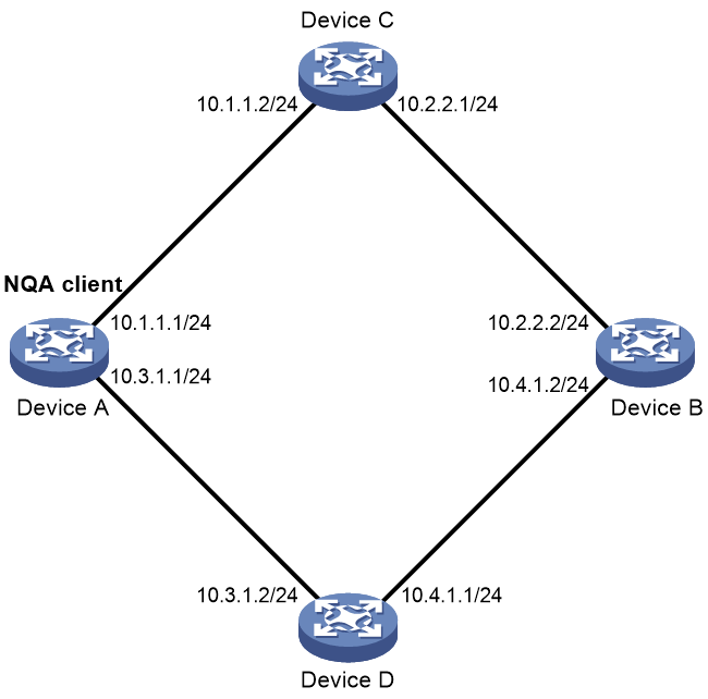
As shown in Figure 2, configure an ICMP echo operation on the NQA client (Device A) to test the round-trip time to Device B. The next hop of Device A is Device C.
Prerequisites
By default, interfaces on the device are in ADM or Administratively Down state. To have an interface operate, you must use the undo shutdown command to enable that interface.
Assign IP addresses to interfaces, as shown in Figure 2. Configure static routes or a routing protocol to make sure the devices can reach each other.
Procedure
# Create an ICMP echo operation.
<DeviceA> system-view
[DeviceA] nqa entry admin test1
[DeviceA-nqa-admin-test1] type icmp-echo
# Specify 10.2.2.2 as the destination IP address of ICMP echo requests.
[DeviceA-nqa-admin-test1-icmp-echo] destination ip 10.2.2.2
# Specify 10.1.1.2 as the next hop. The ICMP echo requests are sent through Device C to Device B.
[DeviceA-nqa-admin-test1-icmp-echo] next-hop ip 10.1.1.2
# Configure the ICMP echo operation to perform 10 probes.
[DeviceA-nqa-admin-test1-icmp-echo] probe count 10
# Set the probe timeout time to 500 milliseconds for the ICMP echo operation.
[DeviceA-nqa-admin-test1-icmp-echo] probe timeout 500
# Configure the ICMP echo operation to repeat every 5000 milliseconds.
[DeviceA-nqa-admin-test1-icmp-echo] frequency 5000
# Enable saving history records.
[DeviceA-nqa-admin-test1-icmp-echo] history-record enable
# Set the maximum number of history records to 10.
[DeviceA-nqa-admin-test1-icmp-echo] history-record number 10
[DeviceA-nqa-admin-test1-icmp-echo] quit
# Start the ICMP echo operation.
[DeviceA] nqa schedule admin test1 start-time now lifetime forever
# After the ICMP echo operation runs for a period of time, stop the operation.
[DeviceA] undo nqa schedule admin test1
Verifying the configuration
# Display the most recent result of the ICMP echo operation.
[DeviceA] display nqa result admin test1
NQA entry (admin admin, tag test1) test results:
Send operation times: 10 Receive response times: 10
Min/Max/Average round trip time: 2/5/3
Square-Sum of round trip time: 96
Last succeeded probe time: 2011-08-23 15:00:01.2
Extended results:
Packet loss ratio: 0%
Failures due to timeout: 0
Failures due to internal error: 0
Failures due to other errors: 0
# Display the history records of the ICMP echo operation.
[DeviceA] display nqa history admin test1
NQA entry (admin admin, tag test) history records:
Index Response Status Time
370 3 Succeeded 2007-08-23 15:00:01.2
369 3 Succeeded 2007-08-23 15:00:01.2
368 3 Succeeded 2007-08-23 15:00:01.2
367 5 Succeeded 2007-08-23 15:00:01.2
366 3 Succeeded 2007-08-23 15:00:01.2
365 3 Succeeded 2007-08-23 15:00:01.2
364 3 Succeeded 2007-08-23 15:00:01.1
363 2 Succeeded 2007-08-23 15:00:01.1
362 3 Succeeded 2007-08-23 15:00:01.1
361 2 Succeeded 2007-08-23 15:00:01.1
The output shows that the packets sent by Device A can reach Device B through Device C. No packet loss occurs during the operation. The minimum, maximum, and average round-trip times are 2, 5, and 3 milliseconds, respectively.
Example: Configuring the DHCP operation
Network configuration
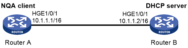
As shown in Figure 3, configure a DHCP operation to test the time required for Router A to obtain an IP address from the DHCP server.
Procedure
# Create a DHCP operation.
<RouterA> system-view
[RouterA] nqa entry admin test1
[RouterA-nqa-admin-test1] type dhcp
# Specify the DHCP server IP address (10.1.1.2) as the destination address.
[RouterA-nqa-admin-test1-dhcp] destination ip 10.1.1.2
# Enable the saving of history records.
[RouterA-nqa-admin-test1-dhcp] history-record enable
[RouterA-nqa-admin-test1-dhcp] quit
# Start the DHCP operation.
[RouterA] nqa schedule admin test1 start-time now lifetime forever
# After the DHCP operation runs for a period of time, stop the operation.
[RouterA] undo nqa schedule admin test1
Verifying the configuration
# Display the most recent result of the DHCP operation.
[RouterA] display nqa result admin test1
NQA entry (admin admin, tag test) test results:
Send operation times: 1 Receive response times: 1
Min/Max/Average round trip time: 512/512/512
Square-Sum of round trip time: 262144
Last succeeded probe time: 2007-11-22 09:54:03.8
Extended results:
Packet loss ratio: 0%
Failures due to timeout: 0
Failures due to internal error: 0
Failures due to other errors: 0
# Display the history records of the DHCP operation.
[RouterA] display nqa history admin test1
NQA entry (admin admin, tag test) history records:
Index Response Status Time
1 512 Succeeded 2007-11-22 09:54:03.8
The output shows that it took Router A 512 milliseconds to obtain an IP address from the DHCP server.
Example: Configuring the DNS operation
Network configuration
As shown in Figure 4, configure a DNS operation to test whether Device A can perform address resolution through the DNS server and test the resolution time.

Prerequisites
By default, interfaces on the device are in ADM or Administratively Down state. To have an interface operate, you must use the undo shutdown command to enable that interface.
Assign IP addresses to interfaces, as shown in Figure 4. Configure static routes or a routing protocol to make sure the devices can reach each other.
Procedure
# Create a DNS operation.
<DeviceA> system-view
[DeviceA] nqa entry admin test1
[DeviceA-nqa-admin-test1] type dns
# Specify the IP address of the DNS server (10.2.2.2) as the destination address.
[DeviceA-nqa-admin-test1-dns] destination ip 10.2.2.2
# Specify host.com as the domain name to be translated.
[DeviceA-nqa-admin-test1-dns] resolve-target host.com
# Enable the saving of history records.
[DeviceA-nqa-admin-test1-dns] history-record enable
[DeviceA-nqa-admin-test1-dns] quit
# Start the DNS operation.
[DeviceA] nqa schedule admin test1 start-time now lifetime forever
# After the DNS operation runs for a period of time, stop the operation.
[DeviceA] undo nqa schedule admin test1
Verifying the configuration
# Display the most recent result of the DNS operation.
[DeviceA] display nqa result admin test1
NQA entry (admin admin, tag test1) test results:
Send operation times: 1 Receive response times: 1
Min/Max/Average round trip time: 62/62/62
Square-Sum of round trip time: 3844
Last succeeded probe time: 2011-11-10 10:49:37.3
Extended results:
Packet loss ratio: 0%
Failures due to timeout: 0
Failures due to internal error: 0
Failures due to other errors: 0
# Display the history records of the DNS operation.
[DeviceA] display nqa history admin test1
NQA entry (admin admin, tag test) history records:
Index Response Status Time
1 62 Succeeded 2011-11-10 10:49:37.3
The output shows that it took Device A 62 milliseconds to translate domain name host.com into an IP address.
Example: Configuring the FTP operation
Network configuration
As shown in Figure 5, configure an FTP operation to test the time required for Device A to upload a file to the FTP server. The login username and password are admin and systemtest, respectively. The file to be transferred to the FTP server is config.txt.

Prerequisites
By default, interfaces on the device are in ADM or Administratively Down state. To have an interface operate, you must use the undo shutdown command to enable that interface.
Assign IP addresses to interfaces, as shown in Figure 5. Configure static routes or a routing protocol to make sure the devices can reach each other.
Procedure
# Create an FTP operation.
<DeviceA> system-view
[DeviceA] nqa entry admin test1
[DeviceA-nqa-admin-test1] type ftp
# Specify the URL of the FTP server.
[DeviceA-nqa-admin-test1-ftp] url ftp://10.2.2.2
# Specify 10.1.1.1 as the source IP address.
[DeviceA-nqa-admin-test1-ftp] source ip 10.1.1.1
# Configure the device to upload file config.txt to the FTP server.
[DeviceA-nqa-admin-test1-ftp] operation put
[DeviceA-nqa-admin-test1-ftp] filename config.txt
# Set the username to admin for the FTP operation.
[DeviceA-nqa-admin-test1-ftp] username admin
# Set the password to systemtest for the FTP operation.
[DeviceA-nqa-admin-test1-ftp] password simple systemtest
# Enable the saving of history records.
[DeviceA-nqa-admin-test1-ftp] history-record enable
[DeviceA-nqa-admin-test1-ftp] quit
# Start the FTP operation.
[DeviceA] nqa schedule admin test1 start-time now lifetime forever
# After the FTP operation runs for a period of time, stop the operation.
[DeviceA] undo nqa schedule admin test1
Verifying the configuration
# Display the most recent result of the FTP operation.
[DeviceA] display nqa result admin test1
NQA entry (admin admin, tag test1) test results:
Send operation times: 1 Receive response times: 1
Min/Max/Average round trip time: 173/173/173
Square-Sum of round trip time: 29929
Last succeeded probe time: 2011-11-22 10:07:28.6
Extended results:
Packet loss ratio: 0%
Failures due to timeout: 0
Failures due to disconnect: 0
Failures due to no connection: 0
Failures due to internal error: 0
Failures due to other errors: 0
# Display the history records of the FTP operation.
[DeviceA] display nqa history admin test1
NQA entry (admin admin, tag test1) history records:
Index Response Status Time
1 173 Succeeded 2011-11-22 10:07:28.6
The output shows that it took Device A 173 milliseconds to upload a file to the FTP server.
Example: Configuring the HTTP operation
Network configuration
As shown in Figure 6, configure an HTTP operation on the NQA client to test the time required to obtain data from the HTTP server.

Prerequisites
By default, interfaces on the device are in ADM or Administratively Down state. To have an interface operate, you must use the undo shutdown command to enable that interface.
Assign IP addresses to interfaces, as shown in Figure 6. Configure static routes or a routing protocol to make sure the devices can reach each other.
Procedure
# Create an HTTP operation.
<DeviceA> system-view
[DeviceA] nqa entry admin test1
[DeviceA-nqa-admin-test1] type http
# Specify the URL of the HTTP server.
[DeviceA-nqa-admin-test1-http] url http://10.2.2.2/index.htm
# Configure the HTTP operation to get data from the HTTP server.
[DeviceA-nqa-admin-test1-http] operation get
# Configure the operation to use HTTP version 1.0.
[DeviceA-nqa-admin-test1-http] version v1.0
# Enable the saving of history records.
[DeviceA-nqa-admin-test1-http] history-record enable
[DeviceA-nqa-admin-test1-http] quit
# Start the HTTP operation.
[DeviceA] nqa schedule admin test1 start-time now lifetime forever
# After the HTTP operation runs for a period of time, stop the operation.
[DeviceA] undo nqa schedule admin test1
Verifying the configuration
# Display the most recent result of the HTTP operation.
[DeviceA] display nqa result admin test1
NQA entry (admin admin, tag test1) test results:
Send operation times: 1 Receive response times: 1
Min/Max/Average round trip time: 64/64/64
Square-Sum of round trip time: 4096
Last succeeded probe time: 2011-11-22 10:12:47.9
Extended results:
Packet loss ratio: 0%
Failures due to timeout: 0
Failures due to disconnect: 0
Failures due to no connection: 0
Failures due to internal error: 0
Failures due to other errors: 0
# Display the history records of the HTTP operation.
[DeviceA] display nqa history admin test1
NQA entry (admin admin, tag test1) history records:
Index Response Status Time
1 64 Succeeded 2011-11-22 10:12:47.9
The output shows that it took Device A 64 milliseconds to obtain data from the HTTP server.
Example: Configuring the SNMP operation
Network configuration
As shown in Figure 7, configure an SNMP operation to test the time the NQA client uses to get a response from the SNMP agent.

Prerequisites
By default, interfaces on the device are in ADM or Administratively Down state. To have an interface operate, you must use the undo shutdown command to enable that interface.
Assign IP addresses to interfaces, as shown in Figure 7. Configure static routes or a routing protocol to make sure the devices can reach each other.
Procedure
1. Configure the SNMP agent (Device B):
# Set the SNMP version to all.
<DeviceB> system-view
[DeviceB] snmp-agent sys-info version all
# Set the read community to public.
[DeviceB] snmp-agent community read public
# Set the write community to private.
[DeviceB] snmp-agent community write private
2. Configure Device A:
# Create an SNMP operation.
<DeviceA> system-view
[DeviceA] nqa entry admin test1
[DeviceA-nqa-admin-test1] type snmp
# Specify 10.2.2.2 as the destination IP address of the SNMP operation.
[DeviceA-nqa-admin-test1-snmp] destination ip 10.2.2.2
# Enable the saving of history records.
[DeviceA-nqa-admin-test1-snmp] history-record enable
[DeviceA-nqa-admin-test1-snmp] quit
# Start the SNMP operation.
[DeviceA] nqa schedule admin test1 start-time now lifetime forever
# After the SNMP operation runs for a period of time, stop the operation.
[DeviceA] undo nqa schedule admin test1
Verifying the configuration
# Display the most recent result of the SNMP operation.
[DeviceA] display nqa result admin test1
NQA entry (admin admin, tag test1) test results:
Send operation times: 1 Receive response times: 1
Min/Max/Average round trip time: 50/50/50
Square-Sum of round trip time: 2500
Last succeeded probe time: 2011-11-22 10:24:41.1
Extended results:
Packet loss ratio: 0%
Failures due to timeout: 0
Failures due to internal error: 0
Failures due to other errors: 0
# Display the history records of the SNMP operation.
[DeviceA] display nqa history admin test1
NQA entry (admin admin, tag test1) history records:
Index Response Status Time
1 50 Succeeded 2011-11-22 10:24:41.1
The output shows that it took Device A 50 milliseconds to receive a response from the SNMP agent.
Example: Configuring the TCP operation
Network configuration
As shown in Figure 8, configure a TCP operation to test the time required for Device A to establish a TCP connection with Device B.

Prerequisites
By default, interfaces on the device are in ADM or Administratively Down state. To have an interface operate, you must use the undo shutdown command to enable that interface.
Assign IP addresses to interfaces, as shown in Figure 8. Configure static routes or a routing protocol to make sure the devices can reach each other.
Procedure
1. Configure Device B:
# Enable the NQA server.
<DeviceB> system-view
[DeviceB] nqa server enable
# Configure a listening service to listen to TCP port 9000 on IP address 10.2.2.2.
[DeviceB] nqa server tcp-connect 10.2.2.2 9000
2. Configure Device A:
# Create a TCP operation.
<DeviceA> system-view
[DeviceA] nqa entry admin test1
[DeviceA-nqa-admin-test1] type tcp
# Specify 10.2.2.2 as the destination IP address.
[DeviceA-nqa-admin-test1-tcp] destination ip 10.2.2.2
# Set the destination port number to 9000.
[DeviceA-nqa-admin-test1-tcp] destination port 9000
# Enable the saving of history records.
[DeviceA-nqa-admin-test1-tcp] history-record enable
[DeviceA-nqa-admin-test1-tcp] quit
# Start the TCP operation.
[DeviceA] nqa schedule admin test1 start-time now lifetime forever
# After the TCP operation runs for a period of time, stop the operation.
[DeviceA] undo nqa schedule admin test1
Verifying the configuration
# Display the most recent result of the TCP operation.
[DeviceA] display nqa result admin test1
NQA entry (admin admin, tag test1) test results:
Send operation times: 1 Receive response times: 1
Min/Max/Average round trip time: 13/13/13
Square-Sum of round trip time: 169
Last succeeded probe time: 2011-11-22 10:27:25.1
Extended results:
Packet loss ratio: 0%
Failures due to timeout: 0
Failures due to disconnect: 0
Failures due to no connection: 0
Failures due to internal error: 0
Failures due to other errors: 0
# Display the history records of the TCP operation.
[DeviceA] display nqa history admin test1
NQA entry (admin admin, tag test1) history records:
Index Response Status Time
1 13 Succeeded 2011-11-22 10:27:25.1
The output shows that it took Device A 13 milliseconds to establish a TCP connection to port 9000 on the NQA server.
Example: Configuring the UDP echo operation
Network configuration
As shown in Figure 9, configure a UDP echo operation on the NQA client to test the round-trip time to Device B. The destination port number is 8000.

Prerequisites
By default, interfaces on the device are in ADM or Administratively Down state. To have an interface operate, you must use the undo shutdown command to enable that interface.
Assign IP addresses to interfaces, as shown in Figure 9. Configure static routes or a routing protocol to make sure the devices can reach each other.
Procedure
1. Configure Device B:
# Enable the NQA server.
<DeviceB> system-view
[DeviceB] nqa server enable
# Configure a listening service to listen to UDP port 8000 on IP address 10.2.2.2.
[DeviceB] nqa server udp-echo 10.2.2.2 8000
2. Configure Device A:
# Create a UDP echo operation.
<DeviceA> system-view
[DeviceA] nqa entry admin test1
[DeviceA-nqa-admin-test1] type udp-echo
# Specify 10.2.2.2 as the destination IP address.
[DeviceA-nqa-admin-test1-udp-echo] destination ip 10.2.2.2
# Set the destination port number to 8000.
[DeviceA-nqa-admin-test1-udp-echo] destination port 8000
# Enable the saving of history records.
[DeviceA-nqa-admin-test1-udp-echo] history-record enable
[DeviceA-nqa-admin-test1-udp-echo] quit
# Start the UDP echo operation.
[DeviceA] nqa schedule admin test1 start-time now lifetime forever
# After the UDP echo operation runs for a period of time, stop the operation.
[DeviceA] undo nqa schedule admin test1
Verifying the configuration
# Display the most recent result of the UDP echo operation.
[DeviceA] display nqa result admin test1
NQA entry (admin admin, tag test1) test results:
Send operation times: 1 Receive response times: 1
Min/Max/Average round trip time: 25/25/25
Square-Sum of round trip time: 625
Last succeeded probe time: 2011-11-22 10:36:17.9
Extended results:
Packet loss ratio: 0%
Failures due to timeout: 0
Failures due to internal error: 0
Failures due to other errors: 0
# Display the history records of the UDP echo operation.
[DeviceA] display nqa history admin test1
NQA entry (admin admin, tag test1) history records:
Index Response Status Time
1 25 Succeeded 2011-11-22 10:36:17.9
The output shows that the round-trip time between Device A and port 8000 on Device B is 25 milliseconds.
Example: Configuring the UDP tracert operation
Network configuration
As shown in Figure 10, configure a UDP tracert operation to determine the routing path from Device A to Device B.

Prerequisites
By default, interfaces on the device are disabled (in ADM or Administratively Down state). To have an interface operate, you must use the undo shutdown command to enable that interface.
Assign IP addresses to interfaces, as shown in Figure 10. Configure static routes or a routing protocol to make sure the devices can reach each other.
Procedure
1. Execute the ip ttl-expires enable command on the intermediate devices and execute the ip unreachables enable command on Device B.
2. Configure Device A:
# Create a UDP tracert operation.
<DeviceA> system-view
[DeviceA] nqa entry admin test1
[DeviceA-nqa-admin-test1] type udp-tracert
# Specify 10.2.2.2 as the destination IP address.
[DeviceA-nqa-admin-test1-udp-tracert] destination ip 10.2.2.2
# Set the destination port number to 33434.
[DeviceA-nqa-admin-test1-udp-tracert] destination port 33434
# Configure Device A to perform three probes to each hop.
[DeviceA-nqa-admin-test1-udp-tracert] probe count 3
# Set the probe timeout time to 500 milliseconds.
[DeviceA-nqa-admin-test1-udp-tracert] probe timeout 500
# Configure the UDP tracert operation to repeat every 5000 milliseconds.
[DeviceA-nqa-admin-test1-udp-tracert] frequency 5000
# Specify HundredGigE 1/0/1 as the output interface for UDP packets.
[DeviceA-nqa-admin-test1-udp-tracert] out interface hundredgige 1/0/1
# Enable the no-fragmentation feature.
[DeviceA-nqa-admin-test1-udp-tracert] no-fragment enable
# Set the maximum number of consecutive probe failures to 6.
[DeviceA-nqa-admin-test1-udp-tracert] max-failure 6
# Set the TTL value to 1 for UDP packets in the start round of the UDP tracert operation.
[DeviceA-nqa-admin-test1-udp-tracert] init-ttl 1
# Start the UDP tracert operation.
[DeviceA] nqa schedule admin test1 start-time now lifetime forever
# After the UDP tracert operation runs for a period of time, stop the operation.
[DeviceA] undo nqa schedule admin test1
Verifying the configuration
# Display the most recent result of the UDP tracert operation.
[DeviceA] display nqa result admin test1
NQA entry (admin admin, tag test1) test results:
Send operation times: 6 Receive response times: 6
Min/Max/Average round trip time: 1/1/1
Square-Sum of round trip time: 1
Last succeeded probe time: 2019-09-09 14:46:06.2
Extended results:
Packet loss in test: 0%
Failures due to timeout: 0
Failures due to internal error: 0
Failures due to other errors: 0
UDP-tracert results:
TTL Hop IP Time
1 3.1.1.1 2019-09-09 14:46:03.2
2 10.2.2.2 2019-09-09 14:46:06.2
# Display the history records of the UDP tracert operation.
[DeviceA] display nqa history admin test1
NQA entry (admin admin, tag test1) history records:
Index TTL Response Hop IP Status Time
1 2 2 10.2.2.2 Succeeded 2013-09-09 14:46:06.2
1 2 1 10.2.2.2 Succeeded 2013-09-09 14:46:05.2
1 2 2 10.2.2.2 Succeeded 2013-09-09 14:46:04.2
1 1 1 3.1.1.1 Succeeded 2013-09-09 14:46:03.2
1 1 2 3.1.1.1 Succeeded 2013-09-09 14:46:02.2
1 1 1 3.1.1.1 Succeeded 2013-09-09 14:46:01.2
Example: Configuring the DLSw operation
Network configuration
As shown in Figure 11, configure a DLSw operation to test the response time of the DLSw device.

Prerequisites
By default, interfaces on the device are in ADM or Administratively Down state. To have an interface operate, you must use the undo shutdown command to enable that interface.
Assign IP addresses to interfaces, as shown in Figure 11. Configure static routes or a routing protocol to make sure the devices can reach each other.
Procedure
# Create a DLSw operation.
<DeviceA> system-view
[DeviceA] nqa entry admin test1
[DeviceA-nqa-admin-test1] type dlsw
# Specify 10.2.2.2 as the destination IP address.
[DeviceA-nqa-admin-test1-dlsw] destination ip 10.2.2.2
# Enable the saving of history records.
[DeviceA-nqa-admin-test1-dlsw] history-record enable
[DeviceA-nqa-admin-test1-dlsw] quit
# Start the DLSw operation.
[DeviceA] nqa schedule admin test1 start-time now lifetime forever
# After the DLSw operation runs for a period of time, stop the operation.
[DeviceA] undo nqa schedule admin test1
Verifying the configuration
# Display the most recent result of the DLSw operation.
[DeviceA] display nqa result admin test1
NQA entry (admin admin, tag test1) test results:
Send operation times: 1 Receive response times: 1
Min/Max/Average round trip time: 19/19/19
Square-Sum of round trip time: 361
Last succeeded probe time: 2011-11-22 10:40:27.7
Extended results:
Packet loss ratio: 0%
Failures due to timeout: 0
Failures due to disconnect: 0
Failures due to no connection: 0
Failures due to internal error: 0
Failures due to other errors: 0
# Display the history records of the DLSw operation.
[DeviceA] display nqa history admin test1
NQA entry (admin admin, tag test1) history records:
Index Response Status Time
1 19 Succeeded 2011-11-22 10:40:27.7
The output shows that the response time of the DLSw device is 19 milliseconds.
Example: Configuring NQA collaboration
Network configuration
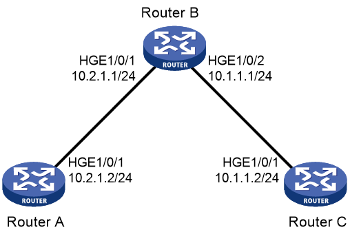
As shown in Figure 12, configure a static route to Router C with Router B as the next hop on Router A. Associate the static route, a track entry, and an ICMP echo operation to monitor the state of the static route.
Prerequisites
Assign IP addresses to interfaces, as shown in Figure 12.
Procedure
1. On Router A, configure a static route, and associate the static route with track entry 1.
<RouterA> system-view
[RouterA] ip route-static 10.1.1.2 24 10.2.1.1 track 1
2. On Router A, configure an ICMP echo operation:
# Create an NQA operation with administrator name admin and operation tag test1.
[RouterA] nqa entry admin test1
# Set the NQA operation type to ICMP echo.
[RouterA-nqa-admin-test1] type icmp-echo
# Specify 10.2.1.1 as the destination IP address.
[RouterA-nqa-admin-test1-icmp-echo] destination ip 10.2.1.1
# Configure the operation to repeat every 100 milliseconds.
[RouterA-nqa-admin-test1-icmp-echo] frequency 100
# Create reaction entry 1. If the number of consecutive probe failures reaches 5, collaboration is triggered.
[RouterA-nqa-admin-test1-icmp-echo] reaction 1 checked-element probe-fail threshold-type consecutive 5 action-type trigger-only
[RouterA-nqa-admin-test1-icmp-echo] quit
# Start the ICMP echo operation.
[RouterA] nqa schedule admin test1 start-time now lifetime forever
3. On Router A, create track entry 1, and associate it with reaction entry 1 of the NQA operation.
[RouterA] track 1 nqa entry admin test1 reaction 1
Verifying the configuration
# Display information about all the track entries on Router A.
[RouterA] display track all
Track ID: 1
State: Positive
Duration: 0 days 0 hours 0 minutes 0 seconds
Notification delay: Positive 0, Negative 0 (in seconds)
Tracked object:
NQA entry: admin test1
Reaction: 1
# Display brief information about active routes in the routing table on Router A.
[RouterA] display ip routing-table
Destinations : 13 Routes : 13
Destination/Mask Proto Pre Cost NextHop Interface
0.0.0.0/32 Direct 0 0 127.0.0.1 InLoop0
10.1.1.0/24 Static 60 0 10.2.1.1 HGE1/0/1
10.2.1.0/24 Direct 0 0 10.2.1.2 HGE1/0/1
10.2.1.0/32 Direct 0 0 10.2.1.2 HGE1/0/1
10.2.1.2/32 Direct 0 0 127.0.0.1 InLoop0
10.2.1.255/32 Direct 0 0 10.2.1.2 HGE1/0/1
127.0.0.0/8 Direct 0 0 127.0.0.1 InLoop0
127.0.0.0/32 Direct 0 0 127.0.0.1 InLoop0
127.0.0.1/32 Direct 0 0 127.0.0.1 InLoop0
127.255.255.255/32 Direct 0 0 127.0.0.1 InLoop0
224.0.0.0/4 Direct 0 0 0.0.0.0 NULL0
224.0.0.0/24 Direct 0 0 0.0.0.0 NULL0
255.255.255.255/32 Direct 0 0 127.0.0.1 InLoop0
The output shows that the static route with the next hop 10.2.1.1 is active, and the status of the track entry is positive.
# Remove the IP address of HundredGigE 1/0/1 on Router B.
<RouterB> system-view
[RouterB] interface hundredgige 1/0/1
[RouterB-HundredGigE1/0/1] undo ip address
# Display information about all the track entries on Router A.
[RouterA] display track all
Track ID: 1
State: Negative
Duration: 0 days 0 hours 0 minutes 0 seconds
Notification delay: Positive 0, Negative 0 (in seconds)
Tracked object:
NQA entry: admin test1
Reaction: 1
# Display brief information about active routes in the routing table on Router A.
[RouterA] display ip routing-table
Destinations : 12 Routes : 12
Destination/Mask Proto Pre Cost NextHop Interface
0.0.0.0/32 Direct 0 0 127.0.0.1 InLoop0
10.2.1.0/24 Direct 0 0 10.2.1.2 HGE1/0/1
10.2.1.0/32 Direct 0 0 10.2.1.2 HGE1/0/1
10.2.1.2/32 Direct 0 0 127.0.0.1 InLoop0
10.2.1.255/32 Direct 0 0 10.2.1.2 HGE1/0/1
127.0.0.0/8 Direct 0 0 127.0.0.1 InLoop0
127.0.0.0/32 Direct 0 0 127.0.0.1 InLoop0
127.0.0.1/32 Direct 0 0 127.0.0.1 InLoop0
127.255.255.255/32 Direct 0 0 127.0.0.1 InLoop0
224.0.0.0/4 Direct 0 0 0.0.0.0 NULL0
224.0.0.0/24 Direct 0 0 0.0.0.0 NULL0
255.255.255.255/32 Direct 0 0 127.0.0.1 InLoop0
The output shows that the static route does not exist, and the status of the track entry is negative.
