- Table of Contents
-
- 06-Layer 3—IP Routing Configuration Guide
- 00-Preface
- 01-Basic IP routing configuration
- 02-Static routing configuration
- 03-RIP configuration
- 04-OSPF configuration
- 05-IS-IS configuration
- 06-Basic BGP configuration
- 07-Advanced BGP configuration
- 08-Policy-based routing configuration
- 09-IPv6 static routing configuration
- 10-RIPng configuration
- 11-OSPFv3 configuration
- 12-IPv6 policy-based routing configuration
- 13-Routing policy configuration
- 14-DCN configuration
- Related Documents
-
| Title | Size | Download |
|---|---|---|
| 07-Advanced BGP configuration | 758.82 KB |
Tuning and optimizing BGP networks
BGP network tuning and optimization tasks at a glance
Enabling BGP to establish an EBGP session over multiple hops
Enabling immediate re-establishment of direct EBGP connections upon link failure
Enabling BGP ORF capabilities negotiation
Enabling BGP ORF capabilities negotiation for a peer or peer group
Enabling nonstandard BGP ORF capabilities negotiation for a peer or peer group
Verifying and maintaining BGP ORF
Enabling 4-byte AS number suppression
Disabling BGP session establishment
About disabling BGP session establishment
Disabling BGP session establishment with a peer or peer group (IPv4 peers)
Disabling BGP session establishment with a peer or peer group (IPv6 peers)
Disabling BGP session establishment with all peers or peer groups
Enabling route refresh (IPv4 peers)
Enabling route refresh (IPv6 peers)
Saving updates (IPv4 unicast address family)
Saving updates (IPv6 unicast address family)
Configuring manual soft-reset (IPv4 unicast address family)
Configuring manual soft-reset (IPv6 unicast address family)
Configuring BGP load balancing
Configuring the BGP Additional Paths feature
Configuring BGP optimal route selection delay
Setting the delay time for responding to recursive next hop changes
Configuring peer flap dampening
Protecting an EBGP peer when memory usage reaches level 2 threshold
Setting a DSCP value for outgoing BGP packets
Disabling route recursion policy control for routes received from a peer or peer group
Flushing the suboptimal BGP route to the RIB
Specifying a label allocation mode
Disabling optimal route selection for labeled routes without tunnel information
Disabling MPLS local IFNET tunnel establishment
BGP network tuning and optimization configuration examples
Example: Configuring BGP load balancing
Example: Configuring the BGP Additional Paths feature
Configuring BGP security features
BGP security feature configuration tasks at a glance
Enabling MD5 authentication for BGP peers
Enabling keychain authentication for BGP peers
Configuring IPsec for IPv6 BGP
Configuring RPKI connection parameters
Applying the BGP RPKI validation state to optimal route selection
Advertising BGP RPKI validation state to a peer or peer group
Verifying and maintaining BGP security features
Verifying and maintaining BGP RPKI
Verifying and maintaining BGP GTSM
IPv4 BGP security feature configuration examples
IPv6 BGP security feature configuration examples
Improving BGP network reliability
BGP network reliability improvement tasks at a glance
Configuring BGP FRR by using a routing policy (IPv4 unicast address family)
Configuring BGP FRR by using a routing policy (IPv6 unicast address family)
Configuring BGP FRR through PIC (IPv4 unicast address family)
Configuring BGP FRR through PIC (IPv6 unicast address family)
IPv4 BGP network reliability improvement configuration examples
Example: Configuring BFD for BGP
IPv6 BGP network reliability improvement configuration examples
Example: Configuring BFD for IPv6 BGP
Example: Configuring IPv6 BGP FRR
Configuring extended BGP features
Extended BGP feature configuration tasks at a glance
Configuring BGP LS route reflection
Specifying an AS number and a router ID for BGP LS messages
Performing manual soft-reset for BGP sessions of LS address family
Verifying and maintaining BGP LS
Configuring the BGP Additional Paths feature for 6PE
Controlling path selection for 6PE
Controlling 6PE route advertisement and reception
Configuring 6PE route reflection
Extended IPv4 BGP feature configuration examples
Extended IPv6 BGP feature configuration examples
Tuning and optimizing BGP networks
BGP network tuning and optimization tasks at a glance
To tune and optimize BGP networks, perform the following tasks:
· Establishing and resetting EBGP sessions
¡ Enabling BGP to establish an EBGP session over multiple hops
¡ Enabling immediate re-establishment of direct EBGP connections upon link failure
· Enabling BGP ORF capabilities negotiation
· Establishing, terminating, and resetting BGP sessions
¡ Enabling 4-byte AS number suppression
¡ Disabling BGP session establishment
· Configuring BGP load balancing
· Configuring the BGP Additional Paths feature
· Configuring BGP optimal route selection delay
· Setting the delay time for responding to recursive next hop changes
· Configuring peer flap dampening
· Protecting an EBGP peer when memory usage reaches level 2 threshold
· Setting a DSCP value for outgoing BGP packets
· Disabling route recursion policy control for routes received from a peer or peer group
· Flushing the suboptimal BGP route to the RIB
· Disabling MPLS local IFNET tunnel establishment
· Configuring label allocation and path selection
¡ Specifying a label allocation mode
¡ Disabling optimal route selection for labeled routes without tunnel information
Enabling BGP to establish an EBGP session over multiple hops
About this task
To establish an EBGP session, two routers must have a direct physical link and use directly connected interfaces. If no direct link is available, you must use the peer ebgp-max-hop command to enable BGP to establish an EBGP session over multiple hops and specify the maximum hops.
Restrictions and guidelines
When the BGP GTSM feature is enabled, two peers can establish an EBGP session after passing GTSM check, regardless of whether the maximum number of hops is reached.
Procedure (IPv4 peers)
1. Enter system view.
system-view
2. Enter BGP instance view or BGP-VPN instance view.
¡ Enter BGP instance view.
bgp as-number [ instance instance-name ]
¡ Enter BGP-VPN instance view.
bgp as-number [ instance instance-name ]
ip vpn-instance vpn-instance-name
3. Enable BGP to establish an EBGP session to an indirectly connected peer or peer group and specify the maximum hop count.
peer { group-name | ipv4-address [ mask-length ] } ebgp-max-hop [ hop-count ]
By default, BGP cannot establish an EBGP session to an indirectly connected peer or peer group.
Procedure (IPv6 peers)
1. Enter system view.
system-view
2. Enter BGP instance view or BGP-VPN instance view.
¡ Enter BGP instance view.
bgp as-number [ instance instance-name ]
¡ Enter BGP-VPN instance view.
bgp as-number [ instance instance-name ]
ip vpn-instance vpn-instance-name
3. Enable BGP to establish an EBGP session to an indirectly connected peer or peer group and specify the maximum hop count.
peer { group-name | ipv6-address [ prefix-length ] } ebgp-max-hop [ hop-count ]
By default, BGP cannot establish an EBGP session to an indirectly connected peer or peer group.
Enabling immediate re-establishment of direct EBGP connections upon link failure
About this task
By default, when the link to a directly connected EBGP peer goes down, the router does not re-establish a session to the peer until the hold time timer expires. This feature enables BGP to immediately recreate the session in that situation. When this feature is disabled, route flapping does not affect EBGP session state.
Procedure
1. Enter system view.
system-view
2. Enter BGP instance view.
bgp as-number [ instance instance-name ]
3. Enable immediate re-establishment of direct EBGP connections upon link failure.
ebgp-interface-sensitive
By default, immediate re-establishment of direct EBGP connections is enabled.
Enabling BGP ORF capabilities negotiation
About BGP ORF
BGP Outbound Route Filtering (ORF) saves the system resources by reducing the route updates that are sent between BGP peers.
The BGP peers negotiate the ORF capabilities through Open messages. After completing the negotiation process, the BGP peers can exchange ORF information (local route reception filtering policy) through route refresh messages. Then, only routes that pass both the local route distribution filtering policy and the received route reception filtering policy can be advertised.
Restrictions and guidelines
You can enable the ORF information sending, receiving, or both sending and receiving capabilities on a BGP router. For two BGP peers to successfully negotiate the ORF capabilities, make sure one end has the sending capability and the other end has the receiving capability.
After you enable BGP ORF capabilities negotiation for a peer, the local device negotiates standard ORF capabilities as defined in RFC with the peer. If the peer uses nonstandard ORF, you must also enable nonstandard ORF capabilities negotiation for the peer.
Enabling BGP ORF capabilities negotiation for a peer or peer group
Procedure (IPv4 unicast)
1. Enter system view.
system-view
2. Enter BGP IPv4 unicast address family view or BGP-VPN IPv4 unicast address family view.
¡ Enter BGP IPv4 unicast address family view.
bgp as-number [ instance instance-name ]
address-family ipv4 [ unicast ]
¡ Enter BGP-VPN IPv4 unicast address family view.
bgp as-number [ instance instance-name ]
ip vpn-instance vpn-instance-name
address-family ipv4 [ unicast ]
3. Enable BGP ORF capabilities negotiation for a peer or peer group.
peer{ group-name | ipv4-address [ mask-length ] | ipv6-address [ prefix-length ] } capability-advertise orf prefix-list { both | receive | send }
By default, BGP ORF capabilities negotiation is disabled for a peer or peer group.
Procedure (IPv6 unicast)
1. Enter system view.
system-view
2. Enter BGP IPv6 unicast address family view or BGP-VPN IPv6 unicast address family view.
¡ Enter BGP IPv6 unicast address family view.
bgp as-number [ instance instance-name ]
address-family ipv6 [ unicast ]
¡ Enter BGP-VPN IPv6 unicast address family view.
bgp as-number [ instance instance-name ]
ip vpn-instance vpn-instance-name
address-family ipv6 [ unicast ]
3. Enable BGP ORF capabilities negotiation for a peer or peer group.
peer { group-name | ipv4-address [ mask-length ] | ipv6-address [ prefix-length ] } capability-advertise orf prefix-list { both | receive | send }
By default, BGP ORF capabilities negotiation is disabled for a peer or peer group.
Enabling nonstandard BGP ORF capabilities negotiation for a peer or peer group
1. Enter system view.
system-view
2. Enter BGP instance view or BGP-VPN instance view.
¡ Enter BGP instance view.
bgp as-number [ instance instance-name ]
¡ Enter BGP-VPN instance view.
bgp as-number [ instance instance-name ]
ip vpn-instance vpn-instance-name
3. Enable nonstandard BGP ORF capabilities negotiation for a peer or peer group.
peer { group-name | ip-address [ mask-length ] | ipv6-address [ prefix-length ] } capability-advertise orf non-standard
By default, nonstandard BGP ORF capabilities negotiation is disabled for a peer or peer group.
Verifying and maintaining BGP ORF
Perform displays tasks in any view.
· Display the ORF prefix information received by an IPv4 unicast peer.
display bgp [ instance instance-name ] peer ipv4 [ unicast ] [ vpn-instance vpn-instance-name ] ipv4-address received prefix-list
· Display the ORF prefix information received by an IPv6 unicast peer.
display bgp [ instance instance-name ] peer ipv6 [ unicast ] [ vpn-instance vpn-instance-name ] ipv6-address received prefix-list
display bgp [ instance instance-name ] peer ipv6 [ unicast ] ipv4-address received prefix-list
Enabling 4-byte AS number suppression
About this task
BGP supports 4-byte AS numbers. The 4-byte AS number occupies four bytes, in the range of 1 to 4294967295. By default, a device sends an OPEN message to the peer device for session establishment. The OPEN message indicates that the device supports 4-byte AS numbers. If the peer device supports 2-byte AS numbers instead of 4-byte AS numbers, the session cannot be established. To resolve this issue, enable the 4-byte AS number suppression feature. The device then sends an OPEN message to inform the peer that it does not support 4-byte AS numbers, so the BGP session can be established.
Restrictions and guidelines
If the peer device supports 4-byte AS numbers, do not enable the 4-byte AS number suppression feature. Otherwise, the BGP session cannot be established.
Procedure (IPv4 peers)
1. Enter system view.
system-view
2. Enter BGP instance view or BGP-VPN instance view.
¡ Enter BGP instance view.
bgp as-number [ instance instance-name ]
¡ Enter BGP-VPN instance view.
bgp as-number [ instance instance-name ]
ip vpn-instance vpn-instance-name
3. Enable 4-byte AS number suppression.
peer { group-name | ipv4-address [ mask-length ] } capability-advertise suppress-4-byte-as
By default, 4-byte AS number suppression is disabled.
Procedure (IPv6 peers)
1. Enter system view.
system-view
2. Enter BGP instance view or BGP-VPN instance view.
¡ Enter BGP instance view.
bgp as-number [ instance instance-name ]
¡ Enter BGP-VPN instance view.
bgp as-number [ instance instance-name ]
ip vpn-instance vpn-instance-name
3. Enable 4-byte AS number suppression.
peer { group-name | ipv6-address [ prefix-length ] } capability-advertise suppress-4-byte-as
By default, 4-byte AS number suppression is disabled.
Disabling BGP session establishment
About disabling BGP session establishment
This task enables you to temporarily tear down BGP sessions to a peer/peer group or all peers/peer groups. You can perform network upgrade and maintenance without needing to delete and reconfigure the peers and peer groups. To recover the sessions, execute the undo peer ignore or undo ignore all-peers command.
If you specify the graceful keyword in the peer ignore command, BGP performs the following tasks:
· Gracefully shuts down the session to the specified peer or peer group in the specified graceful shutdown period of time.
· Advertises all routes to the specified peer or peer group and changes the attribute of the advertised routes to the specified value.
· Advertises routes from the specified peer or peer group to other IBGP peers and peer groups and changes the attribute of the advertised routes to the specified value.
If you specify the graceful keyword in the ignore all-peers command, BGP performs the following tasks:
· Gracefully shuts down the sessions to all peers and peer groups in the specified graceful shutdown period of time.
· Advertises all routes to all peers and peer groups and changes the attribute of the advertised routes to the specified value.
Restrictions and guidelines
For a BGP peer or peer group, the configuration made by the peer ignore command takes precedence over the configuration made by the ignore all-peers command.
Disabling BGP session establishment with a peer or peer group (IPv4 peers)
1. Enter system view.
system-view
2. Enter BGP instance view or BGP-VPN instance view.
¡ Enter BGP instance view.
bgp as-number [ instance instance-name ]
¡ Enter BGP-VPN instance view.
bgp as-number [ instance instance-name ]
ip vpn-instance vpn-instance-name
3. Disable BGP session establishment with a peer or peer group.
peer { group-name | ipv4-address [ mask-length ] } ignore [ graceful graceful-time { community { community-number | aa:nn } | local-preference preference | med med } * ]
By default, BGP can establish a session to a peer or peer group.
|
|
CAUTION: · If a session has been established to a peer, executing this command for the peer tears down the session and clears all related routing information. · If sessions have been established to a peer group, executing this command for the peer group tears down the sessions to all peers in the group and clears all related routing information. |
Disabling BGP session establishment with a peer or peer group (IPv6 peers)
1. Enter system view.
system-view
2. Enter BGP instance view or BGP-VPN instance view.
¡ Enter BGP instance view.
bgp as-number [ instance instance-name ]
¡ Enter BGP-VPN instance view.
bgp as-number [ instance instance-name ]
ip vpn-instance vpn-instance-name
3. Disable BGP session establishment with a peer or peer group.
peer { group-name | ipv6-address [ prefix-length ] } ignore [ graceful graceful-time { community { community-number | aa:nn } | local-preference preference | med med } * ]
By default, BGP can establish a session to a peer or peer group.
|
|
CAUTION: · If a session has been established to a peer, executing this command for the peer tears down the session and clears all related routing information. · If sessions have been established to a peer group, executing this command for the peer group tears down the sessions to all peers in the group and clears all related routing information. |
Disabling BGP session establishment with all peers or peer groups
1. Enter system view.
system-view
2. Enter BGP instance view.
bgp as-number [ instance instance-name ]
3. Disable BGP session establishment with all peers or peer groups.
ignore all-peers [ graceful graceful-time { community { community-number | aa:nn } | local-preference preference | med med } * ]
By default, BGP can establish sessions to all peers and peer groups.
|
|
CAUTION: Executing this command tears down all existing sessions to peers and peer groups and clears all related routing information. |
Configuring BGP soft-reset
About BGP soft-reset
After you modify the route selection policy, for example, modify the preferred value, you must reset BGP sessions to apply the new policy. The reset operation tears down and re-establishes BGP sessions.
To avoid tearing down BGP sessions, you can use one of the following soft-reset methods to apply the new policy:
· Enabling route refresh—The BGP router advertises a ROUTE-REFRESH message to the specified peer, and the peer resends its routing information to the router. After receiving the routing information, the router filters the routing information by using the new policy.
This method requires that both the local router and the peer support route refresh.
· Saving updates—Use the peer keep-all-routes command to save all route updates from the specified peer. After modifying the route selection policy, filter routing information by using the new policy.
This method does not require that the local router and the peer support route refresh but it uses more memory resources to save routes.
· Manual soft-reset—Use the refresh bgp command to enable BGP to send local routing information or advertise a ROUTE-REFRESH message to the specified peer. The peer then resends its routing information. After receiving the routing information, the router filters the routing information by using the new policy.
This method requires that both the local router and the peer support route refresh.
Enabling route refresh (IPv4 peers)
1. Enter system view.
system-view
2. Enter BGP instance view or BGP-VPN instance view.
¡ Enter BGP instance view.
bgp as-number [ instance instance-name ]
¡ Enter BGP-VPN instance view.
bgp as-number [ instance instance-name ]
ip vpn-instance vpn-instance-name
3. Enable BGP route refresh for a peer or peer group.
¡ Enable BGP route refresh for the specified peer or peer group.
peer { group-name | ipv4-address [ mask-length ] } capability-advertise route-refresh
¡ Enable the BGP route refresh, multi-protocol extension, and 4-byte AS number features for the specified peer or peer group.
undo peer { group-name | ipv4-address [ mask-length ] } capability-advertise conventional
By default, the BGP route refresh, multi-protocol extension, and 4-byte AS number features are enabled.
Enabling route refresh (IPv6 peers)
1. Enter system view.
system-view
2. Enter BGP instance view or BGP-VPN instance view.
¡ Enter BGP instance view.
bgp as-number [ instance instance-name ]
¡ Enter BGP-VPN instance view.
bgp as-number [ instance instance-name ]
ip vpn-instance vpn-instance-name
3. Enable BGP route refresh for a peer or peer group.
¡ Enable BGP route refresh for the specified peer or peer group.
peer { group-name | ipv6-address [ prefix-length ] } capability-advertise route-refresh
¡ Enable the BGP route refresh, multi-protocol extension, and 4-byte AS number features for the specified peer or peer group.
undo peer { group-name | ipv6-address [ prefix-length ] } capability-advertise conventional
By default, the BGP route refresh, multi-protocol extension, and 4-byte AS number features are enabled.
Saving updates (IPv4 unicast address family)
1. Enter system view.
system-view
2. Enter BGP IPv4 unicast address family view or BGP-VPN IPv4 unicast address family view.
¡ Enter BGP IPv4 unicast address family view.
bgp as-number [ instance instance-name ]
address-family ipv4 [ unicast ]
¡ Enter BGP-VPN IPv4 unicast address family view.
bgp as-number [ instance instance-name ]
ip vpn-instance vpn-instance-name
address-family ipv4 [ unicast ]
3. Save all route updates from the peer or peer group.
peer { group-name | ipv4-address [ mask-length ] | ipv6-address [ prefix-length ] } keep-all-routes
By default, route updates from peers and peer groups are not saved.
This command takes effect only for the routes received after this command is executed.
Saving updates (IPv6 unicast address family)
1. Enter system view.
system-view
2. Enter BGP IPv6 unicast address family view or BGP-VPN IPv6 unicast address family view.
¡ Enter BGP IPv6 unicast address family view.
bgp as-number [ instance instance-name ]
address-family ipv6 [ unicast ]
¡ Enter BGP-VPN IPv6 unicast address family view.
bgp as-number [ instance instance-name ]
ip vpn-instance vpn-instance-name
address-family ipv6 [ unicast ]
3. Save all route updates from the peer or peer group.
peer { group-name | ipv4-address [ mask-length ] | ipv6-address [ prefix-length ] } keep-all-routes
By default, route updates from peers and peer groups are not saved.
This command takes effect only for the routes received after this command is executed.
Configuring manual soft-reset (IPv4 unicast address family)
1. Enter system view.
system-view
2. Enter BGP instance view or BGP-VPN instance view.
¡ Enter BGP instance view.
bgp as-number [ instance instance-name ]
¡ Enter BGP-VPN instance view.
bgp as-number [ instance instance-name ]
ip vpn-instance vpn-instance-name
3. Enable BGP route refresh for a peer or peer group.
¡ Enable BGP route refresh for the specified peer or peer group.
peer { group-name | ipv4-address [ mask-length ] } capability-advertise route-refresh
¡ Enable the BGP route refresh, multi-protocol extension, and 4-byte AS number features for the specified peer or peer group.
undo peer { group-name | ipv4-address [ mask-length ] } capability-advertise conventional
By default, the BGP route refresh, multi-protocol extension, and 4-byte AS number features are enabled.
4. Execute the quit command twice to return to user view.
quit
5. Perform manual soft-reset. Choose one option as needed:
¡ Perform manual soft-reset on IPv4 sessions in BGP IPv4 address family.
refresh bgp [ instance instance-name ] { ipv4-address [ mask-length ] | all | external | group group-name | internal } { export | import } ipv4 [ unicast ] [ vpn-instance vpn-instance-name ]
¡ Perform manual soft-reset on IPv6 sessions in BGP IPv4 address family.
refresh bgp [ instance instance-name ] { ipv6-address [ mask-length ] | all | external | group group-name | internal } { export | import } ipv4 [ unicast ] [ vpn-instance vpn-instance-name ]
Configuring manual soft-reset (IPv6 unicast address family)
1. Enter system view.
system-view
2. Enter BGP instance view or BGP-VPN instance view.
¡ Enter BGP instance view.
bgp as-number [ instance instance-name ]
¡ Enter BGP-VPN instance view.
bgp as-number [ instance instance-name ]
ip vpn-instance vpn-instance-name
3. Enable BGP route refresh for a peer or peer group.
¡ Enable BGP route refresh for the specified peer or peer group.
peer { group-name | ipv6-address [ prefix-length ] } capability-advertise route-refresh
¡ Enable the BGP route refresh, multi-protocol extension, and 4-byte AS number features for the specified peer or peer group.
undo peer { group-name | ipv6-address [ prefix-length ] } capability-advertise conventional
By default, the BGP route refresh, multi-protocol extension, and 4-byte AS number features are enabled.
4. Execute the quit command twice to return to user view.
quit
5. Perform manual soft-reset. Choose one option as needed:
¡ Perform manual soft-reset on IPv6 sessions in BGP IPv6 address family.
refresh bgp [ instance instance-name ] { ipv6-address [ prefix-length ] | all | external | group group-name | internal } { export | import } ipv6 [ unicast ] [ vpn-instance vpn-instance-name ]
¡ Perform manual soft-reset on IPv4 sessions in BGP IPv6 address family.
refresh bgp [ instance instance-name ] { ipv4-address [ mask-length ] | all | external | group group-name | internal } { export | import } ipv6 [ unicast ] [ vpn-instance vpn-instance-name ]
Configuring BGP load balancing
About this task
Perform this task to specify the maximum number of BGP ECMP routes for load balancing.
Procedure (IPv4 unicast address family)
1. Enter system view.
system-view
2. Enter BGP instance view or BGP-VPN instance view.
¡ Enter BGP instance view.
bgp as-number [ instance instance-name ]
¡ Execute the following commands in sequence to enter BGP-VPN instance view:
bgp as-number [ instance instance-name ]
ip vpn-instance vpn-instance-name
3. (Optional.) Enable BGP to ignore IGP metrics during optimal route selection.
bestroute igp-metric-ignore
By default, BGP compares IGP metrics during optimal route selection, and selects the route with the smallest IGP metric as the optimal route.
BGP cannot use routes with different IGP metrics to implement load balancing. To resolve this issue, you can use this command.
4. Return to system view.
¡ In BGP instance view, execute the quit command once.
¡ In BGP-VPN instance view, execute the quit command twice.
5. Enter BGP IPv4 unicast address family view or BGP-VPN IPv4 unicast address family view.
¡ Enter BGP IPv4 unicast address family view.
bgp as-number [ instance instance-name ]
address-family ipv4 [ unicast ]
¡ Enter BGP-VPN IPv4 unicast address family view.
bgp as-number [ instance instance-name ]
ip vpn-instance vpn-instance-name
address-family ipv4 [ unicast ]
6. Specify the maximum number of BGP ECMP routes for load balancing.
balance [ ebgp | eibgp | ibgp ] number
By default, load balancing is disabled.
7. (Optional.) Enable BGP to ignore the AS_PATH attribute when it implements load balancing.
balance as-path-neglect
By default, BGP does not ignore the AS_PATH attribute when it implements load balancing.
8. (Optional.) Enable BGP to perform load balancing for routes that have different AS_PATH attributes of the same length.
balance as-path-relax [ ebgp | ibgp ]
By default, BGP cannot perform load balancing for routes that have different AS_PATH attributes of the same length.
Procedure (IPv6 unicast address family)
1. Enter system view.
system-view
2. Enter BGP instance view or BGP-VPN instance view.
¡ Enter BGP instance view.
bgp as-number [ instance instance-name ]
¡ Execute the following commands in sequence to enter BGP-VPN instance view:
bgp as-number [ instance instance-name ]
ip vpn-instance vpn-instance-name
3. (Optional.) Enable BGP to ignore IGP metrics during optimal route selection.
bestroute igp-metric-ignore
By default, BGP compares IGP metrics during optimal route selection, and selects the route with the smallest IGP metric as the optimal route.
BGP cannot use routes with different IGP metrics to implement load balancing. To resolve this issue, you can use this command.
4. Return to system view.
¡ In BGP instance view, execute the quit command once.
¡ In BGP-VPN instance view, execute the quit command twice.
5. Enter BGP IPv6 unicast address family view or BGP-VPN IPv6 unicast address family view.
¡ Enter BGP IPv6 unicast address family view.
bgp as-number [ instance instance-name ]
address-family ipv6 [ unicast ]
¡ Enter BGP-VPN IPv6 unicast address family view.
bgp as-number [ instance instance-name ]
ip vpn-instance vpn-instance-name
address-family ipv6 [ unicast ]
6. Specify the maximum number of BGP ECMP routes for load balancing.
balance [ ebgp | eibgp | ibgp ] number
By default, load balancing is disabled.
7. (Optional.) Enable BGP to ignore the AS_PATH attribute when it implements load balancing.
balance as-path-neglect
By default, BGP does not ignore the AS_PATH attribute when it implements load balancing.
8. (Optional.) Enable BGP to perform load balancing for routes that have different AS_PATH attributes of the same length.
balance as-path-relax [ ebgp | ibgp ]
By default, BGP cannot perform load balancing for routes that have different AS_PATH attributes of the same length.
Configuring the BGP Additional Paths feature
About this task
By default, BGP advertises only one optimal route. When the optimal route fails, traffic forwarding will be interrupted until route convergence completes.
The BGP Additional Paths (Add-Path) feature enables BGP to advertise multiple routes with the same prefix and different next hops to a peer or peer group. When the optimal route fails, the suboptimal route becomes the optimal route, which shortens the traffic interruption time.
You can enable the BGP additional path sending, receiving, or both sending and receiving capabilities on a BGP peer. For two BGP peers to successfully negotiate the Additional Paths capabilities, make sure one end has the sending capability and the other end has the receiving capability.
Procedure (IPv4 unicast address family)
1. Enter system view.
system-view
2. Enter BGP IPv4 unicast address family view or BGP-VPN IPv4 unicast address family view.
¡ Enter BGP IPv4 unicast address family view.
bgp as-number [ instance instance-name ]
address-family ipv4 [ unicast ]
¡ Enter BGP-VPN IPv4 unicast address family view.
bgp as-number [ instance instance-name ]
ip vpn-instance vpn-instance-name
address-family ipv4 [ unicast ]
3. Configure the BGP Additional Paths capabilities.
peer { group-name | ipv4-address [ mask-length ] | ipv6-address [ prefix-length ] } additional-paths { receive | send } *
By default, no BGP Additional Paths capabilities are configured.
4. Set the maximum number of Add-Path optimal routes that can be advertised to a peer or peer group.
peer { group-name | ipv4-address [ mask-length ] | ipv6-address [ prefix-length ] } advertise additional-paths best number
By default, a maximum of one Add-Path optimal route can be advertised to a peer or peer group.
5. Set the maximum number of Add-Path optimal routes that can be advertised to all peers.
additional-paths select-best best-number
By default, a maximum of one Add-Path optimal route can be advertised to all peers.
Procedure (IPv6 unicast address family)
1. Enter system view.
system-view
2. Enter BGP IPv6 unicast address family view or BGP-VPN IPv6 unicast address family view.
¡ Enter BGP IPv6 unicast address family view.
bgp as-number [ instance instance-name ]
address-family ipv6 [ unicast ]
¡ Enter BGP-VPN IPv6 unicast address family view.
bgp as-number [ instance instance-name ]
ip vpn-instance vpn-instance-name
address-family ipv6 [ unicast ]
3. Configure the BGP Additional Paths capabilities.
peer { group-name | ipv4-address [ mask-length ] | ipv6-address [ prefix-length ] } additional-paths { receive | send } *
By default, no BGP Additional Paths capabilities are configured.
4. Set the maximum number of Add-Path optimal routes that can be advertised to a peer or peer group.
peer { group-name | ipv4-address [ mask-length ] | ipv6-address [ prefix-length ] } advertise additional-paths best number
By default, a maximum of one Add-Path optimal route can be advertised to a peer or peer group.
5. Set the maximum number of Add-Path optimal routes that can be advertised to all peers.
additional-paths select-best best-number
By default, a maximum of one Add-Path optimal route can be advertised to all peers.
Configuring BGP optimal route selection delay
About this task
Typically BGP optimal route selection is triggered in real time by the events such as attribute change, configuration change, and route recursion. To avoid packet loss upon switchover between redundant links, you can perform this task to delay optimal route selection.
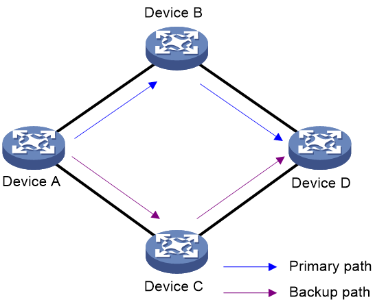
As shown in Figure 1, BGP runs on all devices in the network. Device A and Device D uses the primary path for communication. When the primary path fails, Device A and Device D switch to the backup path for communication and then back to the primary path after the primary path recovers. In such case, traffic loss might occur if Device A forwards packets through Device B before Device B completes route convergence. You can configure optimal route selection delay on Device A to resolve the problem.
Restrictions and guidelines
Follow these restrictions and guidelines when you configure this feature:
· The optimal route selection delay setting applies only when multiple effective routes with the same prefix exist after a route change occurs.
· For routes being delayed for optimal route selection, modifying the optimal route selection delay timer has the following effects:
¡ If you modify the delay timer to a non-zero value, the routes are not affected, and they still use the original delay timer.
¡ If you execute the undo form of the route-select delay command or modify the delay timer to 0, the device performs optimal route selection immediately.
· If you execute the command multiple times for an address family, the most recent configuration takes effect.
· The optimal route selection delay configuration does not apply to the following conditions:
¡ A route change is caused by execution of a command or by route withdrawal.
¡ After a route change occurs, only one route exists for a specific destination network.
¡ An active/standby process switchover occurs.
¡ A route change occurs among equal-cost routes.
¡ Only the optimal and suboptimal routes exist when FRR is configured.
¡ Optimal route selection is triggered by a redistributed route.
¡ The next hop of the optimal route changes and a route with the same prefix is waiting for the delay timer to expire.
Procedure (IPv4 unicast address family)
1. Enter system view.
system-view
2. Enter BGP IPv4 unicast address family view or BGP-VPN IPv4 unicast address family view.
¡ Enter BGP IPv4 unicast address family view.
bgp as-number [ instance instance-name ]
address-family ipv4 [ unicast ]
¡ Enter BGP-VPN IPv4 unicast address family view.
bgp as-number [ instance instance-name ]
ip vpn-instance vpn-instance-name
address-family ipv4 [ unicast ]
3. Set the optimal route selection delay timer.
route-select delay delay-value
By default, the optimal route selection delay timer is 0 seconds, which means optimal route selection is not delayed.
Procedure (IPv6 unicast address family)
1. Enter system view.
system-view
2. Enter BGP IPv6 unicast address family view or BGP-VPN IPv6 unicast address family view.
¡ Enter BGP IPv6 unicast address family view.
bgp as-number [ instance instance-name ]
address-family ipv6 [ unicast ]
¡ Enter BGP-VPN IPv6 unicast address family view.
bgp as-number [ instance instance-name ]
ip vpn-instance vpn-instance-name
address-family ipv6 [ unicast ]
3. Set the optimal route selection delay timer.
route-select delay delay-value
By default, the optimal route selection delay timer is 0 seconds, which means optimal route selection is not delayed.
Setting the delay time for responding to recursive next hop changes
About this task
Next hop changes include the following types:
· Critical next hop changes—Changes that cause route unreachability and service interruption. For example, a BGP route cannot find a recursive next hop (a physical interface or tunnel interface) because of network failures.
· Noncritical next hop changes—A recursive or related route changes but the change does not cause route unreachability or service interruption. For example, the recursive next hop (a physical interface or tunnel interface) of a BGP route changes but traffic forwarding is not affected.
When recursive or related routes change frequently, configure this feature to reduce unnecessary path selection and update messages and prevent traffic loss.
Restrictions and guidelines
To avoid traffic loss, do not configure this feature if only one route is available to a specific destination.
Set an appropriate delay time based on your network condition. A short delay time cannot reduce unnecessary path selection or update messages, and a long delay time might cause traffic loss.
Procedure (IPv4 unicast address family)
1. Enter system view.
system-view
2. Enter BGP IPv4 unicast address family view or BGP-VPN IPv4 unicast address family view.
¡ Enter BGP IPv4 unicast address family view.
bgp as-number [ instance instance-name ]
address-family ipv4 [ unicast ]
¡ Enter BGP-VPN IPv4 unicast address family view.
bgp as-number [ instance instance-name ]
ip vpn-instance vpn-instance-name
address-family ipv4 [ unicast ]
3. Set the delay time for responding to recursive next hop changes.
nexthop recursive-lookup [ non-critical-event ] delay [ delay-value ]
By default, BGP responds to recursive next hop changes immediately.
Procedure (IPv6 unicast address family)
1. Enter system view.
system-view
2. Enter BGP IPv6 unicast address family view or BGP-VPN IPv6 unicast address family view.
¡ Enter BGP IPv6 unicast address family view.
bgp as-number [ instance instance-name ]
address-family ipv6 [ unicast ]
¡ Enter BGP-VPN IPv6 unicast address family view.
bgp as-number [ instance instance-name ]
ip vpn-instance vpn-instance-name
address-family ipv6 [ unicast ]
3. Set the delay time for responding to recursive next hop changes.
nexthop recursive-lookup [ non-critical-event ] delay [ delay-value ]
By default, BGP responds to recursive next hop changes immediately.
Configuring peer flap dampening
About this task
Perform this task to dampen a BGP peer when the peer state frequently changes between up and down. BGP increases the idle time of the peer each time the peer comes up until the maximum idle time is reached. To exit the dampened state, the peer must remain in Established state for a time period longer than the minimum established time. After the peer exits the dampened state, BGP resets the idle time of the peer when the peer comes up again.
Restrictions and guidelines
Set a maximum idle time and a minimum established time based on your network condition.
Procedure
1. Enter system view.
system-view
2. Enter BGP instance view or BGP-VPN instance view.
¡ Enter BGP instance view.
bgp as-number [ instance instance-name ]
¡ Enter BGP-VPN instance view.
bgp as-number [ instance instance-name ]
ip vpn-instance vpn-instance-name
3. Configure flap dampening for a peer or peer group.
peer { group-name | ipv4-address | ipv6-address } flap-dampen [ max-idle-time max-time | min-established-time min-time ]*
By default, flap dampening is disabled for all peers and peer groups.
Protecting an EBGP peer when memory usage reaches level 2 threshold
About this task
Memory usage includes the following threshold levels: normal, level 1, level 2, and level 3. When the level 2 threshold is reached, BGP periodically tears down an EBGP session to release memory resources until the memory usage falls below the level 2 threshold. You can configure this feature to avoid tearing down the EBGP session to an EBGP peer when the memory usage reaches the level 2 threshold.
For more information about memory usage thresholds, see device management configuration in Fundamentals Configuration Guide.
Procedure (IPv4 peers)
1. Enter system view.
system-view
2. Enter BGP instance view or BGP-VPN instance view.
¡ Enter BGP instance view.
bgp as-number [ instance instance-name ]
¡ Enter BGP-VPN instance view.
bgp as-number [ instance instance-name ]
ip vpn-instance vpn-instance-name
3. Configure BGP to protect an EBGP peer or peer group when the memory usage reaches level 2 threshold.
peer { group-name | ipv4-address [ mask-length ] } low-memory-exempt
By default, BGP periodically tears down an EBGP session to release memory resources when level 2 threshold is reached.
Procedure (IPv6 peers)
1. Enter system view.
system-view
2. Enter BGP instance view or BGP-VPN instance view.
¡ Enter BGP instance view.
bgp as-number [ instance instance-name ]
¡ Enter BGP-VPN instance view.
bgp as-number [ instance instance-name ]
ip vpn-instance vpn-instance-name
3. Configure BGP to protect an EBGP peer or peer group when the memory usage reaches level 2 threshold.
peer { group-name | ipv6-address [ prefix-length ] } low-memory-exempt
By default, BGP tears down an EBGP session to release memory resources periodically when level 2 threshold is reached.
Setting a DSCP value for outgoing BGP packets
About this task
The DSCP value of an IP packet specifies the priority level of the packet and affects the transmission priority of the packet.
Procedure
1. Enter system view.
system-view
2. Enter BGP instance view or BGP-VPN instance view.
¡ Enter BGP instance view.
bgp as-number [ instance instance-name ]
¡ Enter BGP-VPN instance view.
bgp as-number [ instance instance-name ]
ip vpn-instance vpn-instance-name
3. Set a DSCP value for outgoing BGP packets.
peer { group-name | ipv4-address [ mask-length ] | ipv6-address [ prefix-length ] } dscp dscp-value
By default, the DSCP value for outgoing BGP packets is 48.
Disabling route recursion policy control for routes received from a peer or peer group
About this task
If you configure routing policy-based recursive lookup for BGP routes, this route recursion policy applies to BGP routes learned from all peers. This task allows you to disable route recursion policy control for routes learned from certain peers, for example, direct EBGP peers.
Procedure
1. Enter system view.
system-view
2. Enter BGP instance view or BGP-VPN instance view.
¡ Enter BGP instance view.
bgp as-number [ instance instance-name ]
¡ Enter BGP-VPN instance view.
bgp as-number [ instance instance-name ]
ip vpn-instance vpn-instance-name
3. Disable route recursion policy control for routes received from the specified peer or peer group.
peer { group-name | ip-address [ mask-length ] | ipv6-address [ prefix-length ] } nexthop-recursive-policy disable
By default, the route recursion policy applies to routes received from the peer or peer group.
Flushing the suboptimal BGP route to the RIB
About this task
This feature flushes the suboptimal BGP route to the RIB when the following conditions are met:
· The optimal route is generated by the network command or is redistributed by the import-route command.
· The suboptimal route is received from a BGP peer.
After the suboptimal route is flushed to the RIB on a network, BGP immediately switches traffic to the suboptimal route when the optimal route fails.
For example, the device has a static route to the subnet 1.1.1.0/24 that has a higher priority than a BGP route. BGP redistributes the static route and receives a route to 1.1.1.0/24 from a peer. After the flush suboptimal-route command is executed, BGP flushes the received BGP route to the RIB as the suboptimal route. When the static route fails, BGP immediately switches traffic to the suboptimal route if inter-protocol FRR is enabled. For more information about inter-protocol FRR, see "Configuring basic IP routing."
Procedure
1. Enter system view.
system-view
2. Enter BGP view.
bgp as-number [ instance instance-name ]
3. Flush the suboptimal BGP route to the RIB.
flush suboptimal-route
By default, BGP is disabled from flushing the suboptimal BGP route to the RIB, and only the optimal route is flushed to the RIB.
Specifying a label allocation mode
About this task
BGP supports the following label allocation modes:
· Per-prefix—Allocates a label to each route prefix.
· Per-next-hop—Allocates a label to each next hop. This mode is applicable when the number of labels required by the per-prefix mode exceeds the maximum number of labels supported by the device.
· Per-VPN-instance—Allocates a label to each VPN instance. This mode is applicable when the number of labels required by the per-next-hop mode exceeds the maximum number of labels supported by the device.
Restrictions and guidelines
When you specify the per-prefix or per-next-hop label allocation mode, you can execute the vpn popgo command to specify the POPGO forwarding mode on an egress PE. The egress PE will pop the label for each packet and forward the packet out of the interface corresponding to the label.
When you specify the per-VPN instance label allocation mode, do not execute the vpn popgo command because it is mutually exclusive with the label-allocation-mode per-vrf command. The egress PE will pop the label for each packet and forward the packet through the FIB table.
Procedure
1. Enter system view.
system-view
2. Enter BGP instance view.
bgp as-number [ instance instance-name ]
3. Specify a label allocation mode.
label-allocation-mode { per-prefix | per-vrf }
By default, BGP allocates labels on a per-next-hop basis.
|
|
CAUTION: A change to the label allocation mode enables BGP to re-advertise all routes, which will cause service interruption. Use this command with caution. |
Disabling optimal route selection for labeled routes without tunnel information
1. Enter system view.
system-view
2. Enter BGP instance view.
bgp as-number [ instance instance-name ]
3. Disable optimal route selection for labeled routes without tunnel information.
labeled-route ignore-no-tunnel
By default, labeled routes without tunnel information can participate in optimal route selection.
Disabling MPLS local IFNET tunnel establishment
About this task
An MPLS local IFNET tunnel is automatically established between MP-EBGP peers. Only directly connected MP-EBGP peers are able to forward traffic through this tunnel.
For two indirectly connected MP-EBGP peers, traffic between them is interrupted upon failover to the MPLS local IFNET tunnel. To avoid this issue, you can disable BGP from establishing MPLS local IFNET tunnels to the specified EBGP peer or peer group.
Restrictions and guidelines
Disabling MPLS local IFNET tunnel establishment deletes the MPLS local IFNET tunnels already established to the specified EBGP peer or peer group.
Disabling BGP from establishing MPLS local IFNET tunnels to directly connected EBGP peers and peer groups will cause traffic loss. Make sure you fully understand the impact before performing the operation.
Procedure
1. Enter system view.
system-view
2. Enter BGP instance view or BGP-VPN instance view.
¡ Enter BGP instance view.
bgp as-number [ instance instance-name ]
¡ Enter BGP-VPN instance view.
bgp as-number [ instance instance-name ]
ip vpn-instance vpn-instance-name
3. Disable MPLS local IFNET tunnel establishment to the specified EBGP peer or peer group.
peer { group name | ipv4-address [ mask-length ] } mpls-local-ifnet disable
By default, MPLS local IFNET tunnel establishment is enabled. Two MP-EBGP peers automatically establish an MPLS local IFNET tunnel after they exchange labeled routes and VPNv4 routes.
Resetting BGP sessions
About this task
A reset operation terminates and re-establishes BGP sessions in order to validate configuration changes and update routing information.
Restrictions and guidelines
A reset operation tears down BGP sessions for a short period of time.
Procedure
Perform reset tasks in user view.
· Resets BGP sessions for the IPv4 unicast address family.
reset bgp [ instance instance-name ] { as-number | ipv4-address [ mask-length ] | all | external | group group-name | internal } ipv4 [ unicast ] [ vpn-instance vpn-instance-name ]
reset bgp [ instance instance-name ] ipv6-address [ prefix-length ] ipv4 [ unicast ] [ vpn-instance vpn-instance-name ]
· Resets BGP sessions for the IPv6 unicast address family.
reset bgp [ instance instance-name ] { as-number | ipv6-address [ prefix-length ] | all | external | group group-name | internal } ipv6 [ unicast ] [ vpn-instance vpn-instance-name ]
reset bgp ipv4-address [ mask-length ] ipv6 [ unicast ] [ vpn-instance vpn-instance-name ]
· Resets all BGP sessions.
reset bgp [ instance instance-name ] all
For more information about the reset commands, see Basic BGP commands in Layer 3—IP Routing Command Reference.
BGP network tuning and optimization configuration examples
Example: Configuring BGP load balancing
Network configuration
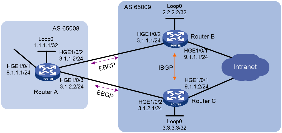
As shown in Figure 2, run EBGP between Router A and Router B, and between Router A and Router C. Run IBGP between Router B and Router C.
Configure load balancing over the two EBGP links on Router A.
Procedure
|
|
NOTE: By default, interfaces on the device are disabled (in ADM or Administratively Down state). To have an interface operate, you must use the undo shutdown command to enable that interface. |
1. Configure IP addresses for interfaces. (Details not shown.)
2. Configure BGP connections:
¡ On Router A, establish EBGP connections with Router B and Router C. Configure BGP to advertise network 8.1.1.0/24 to Router B and Router C. This allows Router B and Router C can access the internal network connected to Router A.
¡ On Router B, establish an EBGP connection with Router A and an IBGP connection with Router C. Configure BGP to advertise network 9.1.1.0/24 to Router A, so that Router A can access the intranet through Router B. Configure a static route to interface loopback 0 on Router C (or use a routing protocol like OSPF) to establish the IBGP connection.
¡ On Router C, establish an EBGP connection with Router A and an IBGP connection with Router B. Configure BGP to advertise network 9.1.1.0/24 to Router A, so that Router A can access the intranet through Router C. Configure a static route to interface loopback 0 on Router B (or use another protocol like OSPF) to establish the IBGP connection.
# Configure Router A.
<RouterA> system-view
[RouterA] bgp 65008
[RouterA-bgp-default] router-id 1.1.1.1
[RouterA-bgp-default] peer 3.1.1.1 as-number 65009
[RouterA-bgp-default] peer 3.1.2.1 as-number 65009
[RouterA-bgp-default] address-family ipv4 unicast
[RouterA-bgp-default-ipv4] peer 3.1.1.1 enable
[RouterA-bgp-default-ipv4] peer 3.1.2.1 enable
[RouterA-bgp-default-ipv4] network 8.1.1.0 24
[RouterA-bgp-default-ipv4] quit
[RouterA-bgp-default] quit
# Configure Router B.
<RouterB> system-view
[RouterB] bgp 65009
[RouterB-bgp-default] router-id 2.2.2.2
[RouterB-bgp-default] peer 3.1.1.2 as-number 65008
[RouterB-bgp-default] peer 3.3.3.3 as-number 65009
[RouterB-bgp-default] peer 3.3.3.3 connect-interface loopback 0
[RouterB-bgp-default] address-family ipv4 unicast
[RouterB-bgp-default-ipv4] peer 3.1.1.2 enable
[RouterB-bgp-default-ipv4] peer 3.3.3.3 enable
[RouterB-bgp-default-ipv4] network 9.1.1.0 24
[RouterB-bgp-default-ipv4] quit
[RouterB-bgp-default] quit
[RouterB] ip route-static 3.3.3.3 32 9.1.1.2
# Configure Router C.
<RouterC> system-view
[RouterC] bgp 65009
[RouterC-bgp-default] router-id 3.3.3.3
[RouterC-bgp-default] peer 3.1.2.2 as-number 65008
[RouterC-bgp-default] peer 2.2.2.2 as-number 65009
[RouterC-bgp-default] peer 2.2.2.2 connect-interface loopback 0
[RouterC-bgp-default] address-family ipv4 unicast
[RouterC-bgp-default-ipv4] peer 3.1.2.2 enable
[RouterC-bgp-default-ipv4] peer 2.2.2.2 enable
[RouterC-bgp-default-ipv4] network 9.1.1.0 24
[RouterC-bgp-default-ipv4] quit
[RouterC-bgp-default] quit
[RouterC] ip route-static 2.2.2.2 32 9.1.1.1
# Display the BGP routing table on Router A.
[RouterA] display bgp routing-table ipv4
Total number of routes: 3
BGP local router ID is 1.1.1.1
Status codes: * - valid, > - best, d - dampened, h - history,
s - suppressed, S - stale, i - internal, e - external
a – additional-path
Origin: i - IGP, e - EGP, ? - incomplete
Network NextHop MED LocPrf PrefVal Path/Ogn
* > 8.1.1.0/24 8.1.1.1 0 32768 i
* >e 9.1.1.0/24 3.1.1.1 0 0 65009i
* e 3.1.2.1 0 0 65009i
¡ The output shows two valid routes to destination 9.1.1.0/24. The route with next hop 3.1.1.1 is marked with a greater-than sign (>), indicating that it is the optimal route. The route with next hop 3.1.2.1 is marked with an asterisk (*), indicating that it is a valid route, but not the optimal route.
¡ By using the display ip routing-table command, you can find there is only one route to 9.1.1.0/24 with next hop 3.1.1.1 and output interface HundredGigE 1/0/2.
3. On Router A, configure the maximum number of ECMP routes destined for AS 65009 as 2 to improve link usage.
[RouterA] bgp 65008
[RouterA-bgp-default] address-family ipv4 unicast
[RouterA-bgp-default-ipv4] balance 2
[RouterA-bgp-default-ipv4] quit
[RouterA-bgp-default] quit
Verifying the configuration
# Display the BGP routing table on Router A.
[RouterA] display bgp routing-table ipv4
Total number of routes: 3
BGP local router ID is 1.1.1.1
Status codes: * - valid, > - best, d - dampened, h - history,
s - suppressed, S - stale, i - internal, e - external
a – additional-path
Origin: i - IGP, e - EGP, ? - incomplete
Network NextHop MED LocPrf PrefVal Path/Ogn
* > 8.1.1.0/24 8.1.1.1 0 32768 i
* >e 9.1.1.0/24 3.1.1.1 0 0 65009i
* >e 3.1.2.1 0 0 65009i
· The output shows that there are two valid routes to the destination 9.1.1.0/24, and both of them are the optimal routes.
· By using the display ip routing-table command, you can find there are two routes to 9.1.1.0/24. One has next hop 3.1.1.1 and output interface HundredGigE 1/0/2, and the other has next hop 3.1.2.1 and output interface HundredGigE 1/0/3.
Example: Configuring the BGP Additional Paths feature
Network configuration
As shown in Figure 3, all routers run BGP. EBGP runs between Router A and Router B, and between Router A and Router C. IBGP runs between Router B and Router D, between Router C and Router D, and between Router D and Router E. Router D is a route reflector and Router E is its client.
Configure the BGP Additional Paths feature to enable Router E to learn routes with the same prefix and different next hops from Router B and Router C.
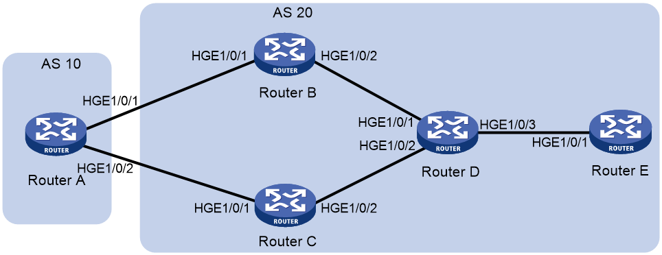
Table 1 Interface and IP address assignment
|
Device |
Interface |
IP address |
Device |
Interface |
IP address |
|
Router A |
HGE1/0/1 |
10.1.1.1/24 |
Router D |
HGE1/0/1 |
30.1.1.1/24 |
|
|
HGE1/0/2 |
20.1.1.1/24 |
|
HGE1/0/2 |
40.1.1.1/24 |
|
Router B |
HGE1/0/1 |
10.1.1.2/24 |
|
HGE1/0/3 |
50.1.1.1/24 |
|
|
HGE1/0/2 |
30.1.1.2/24 |
Router E |
HGE1/0/1 |
50.1.1.2/24 |
|
Router C |
HGE1/0/1 |
20.1.1.2/24 |
|
|
|
|
|
HGE1/0/2 |
40.1.1.2/24 |
|
|
|
Procedure
|
|
NOTE: By default, interfaces on the device are disabled (in ADM or Administratively Down state). To have an interface operate, you must use the undo shutdown command to enable that interface. |
1. Configure IP addresses for interfaces. (Details not shown.)
2. Configure BGP connections:
# Configure Router A.
<RouterA> system-view
[RouterA] bgp 10
[RouterA-bgp-default] peer 10.1.1.2 as-number 20
[RouterA-bgp-default] peer 20.1.1.2 as-number 20
[RouterA-bgp-default] address-family ipv4 unicast
[RouterA-bgp-default-ipv4] peer 10.1.1.2 enable
[RouterA-bgp-default-ipv4] peer 20.1.1.2 enable
# Configure Router B.
<RouterB> system-view
[RouterB] bgp 20
[RouterB-bgp-default] peer 10.1.1.1 as-number 10
[RouterB-bgp-default] peer 30.1.1.1 as-number 20
[RouterB-bgp-default] address-family ipv4 unicast
[RouterB-bgp-default-ipv4] peer 10.1.1.1 enable
[RouterB-bgp-default-ipv4] peer 30.1.1.1 enable
# Configure Router C.
<RouterC> system-view
[RouterC] bgp 20
[RouterC-bgp-default] peer 20.1.1.1 as-number 10
[RouterC-bgp-default] peer 40.1.1.1 as-number 20
[RouterC-bgp-default] address-family ipv4 unicast
[RouterC-bgp-default-ipv4] peer 10.1.1.1 enable
[RouterC-bgp-default-ipv4] peer 30.1.1.1 enable
# Configure Router D.
<RouterD> system-view
[RouterD] bgp 20
[RouterD-bgp-default] peer 30.1.1.2 as-number 20
[RouterD-bgp-default] peer 40.1.1.2 as-number 20
[RouterD-bgp-default] peer 50.1.1.2 as-number 20
[RouterD-bgp-default] address-family ipv4 unicast
[RouterD-bgp-default-ipv4] peer 30.1.1.2 enable
[RouterD-bgp-default-ipv4] peer 40.1.1.2 enable
[RouterD-bgp-default-ipv4] peer 50.1.1.2 enable
# Configure Router E.
<RouterE> system-view
[RouterE] bgp 20
[RouterE-bgp-default] peer 50.1.1.1 as-number 20
[RouterE-bgp-default] address-family ipv4 unicast
[RouterE-bgp-default-ipv4] peer 50.1.1.1 enable
3. Configure Router A to advertise network 10.1.1.0/24.
[RouterA-bgp-default-ipv4] network 10.1.1.0 24
4. Set the local router as the next hop for routes sent to a peer:
# Configure Router B.
[RouterB-bgp-default-ipv4] peer 30.1.1.1 next-hop-local
# Configure Router C.
[RouterC-bgp-default-ipv4] peer 40.1.1.1 next-hop-local
5. Configure Router D as a route reflector.
[RouterD-bgp-default-ipv4] peer 50.1.1.2 reflect-client
6. Configure the Additional Paths feature:
# Enable the additional path sending capability on Router D.
[RouterD-bgp-default-ipv4] peer 50.1.1.2 additional-paths send
# Set the maximum number to 2 for Add-Path optimal routes that can be advertised.
[RouterD-bgp-default-ipv4] additional-paths select-best 2
# Set the maximum number to 2 for Add-Path optimal routes that can be advertised to peer 50.1.1.2.
[RouterD-bgp-default-ipv4] peer 50.1.1.2 advertise additional-paths best 2
# Enable the additional path receiving capability on Router E.
[RouterE-bgp-default-ipv4] peer 50.1.1.1 additional-paths receive
Verifying the configuration
# Display BGP routing information on Router E.
[Router E] display bgp routing-table ipv4
Total number of routes: 2
BGP local router ID is 50.1.1.2
Status codes: * - valid, > - best, d - dampened, h - history
s - suppressed, S - stale, i - internal, e - external
a - additional-path
Origin: i - IGP, e - EGP, ? - incomplete
Network NextHop MED LocPrf PrefVal Path/Ogn
i 10.1.1.0/24 30.1.1.2 0 100 0 10i
i 40.1.1.2 0 100 0 10i
The output shows that Router D has learned two routes with the same prefix and different next hops.
Configuring BGP security features
BGP security feature configuration tasks at a glance
To configure BGP security features, perform the following tasks:
· Enabling MD5 authentication for BGP peers
· Enabling keychain authentication for BGP peers
· Configuring IPsec for IPv6 BGP
Enabling MD5 authentication for BGP peers
About this task
MD5 authentication provides the following benefits:
· Peer authentication ensures that only BGP peers that have the same password can establish TCP connections.
· Integrity check ensures that BGP packets exchanged between peers are intact.
Procedure (IPv4 peers)
1. Enter system view.
system-view
2. Enter BGP instance view or BGP-VPN instance view.
¡ Enter BGP instance view.
bgp as-number [ instance instance-name ]
¡ Enter BGP-VPN instance view.
bgp as-number [ instance instance-name ]
ip vpn-instance vpn-instance-name
3. Enable MD5 authentication for a BGP peer group or peer.
peer { group-name | ipv4-address [ mask-length ] } password { cipher | simple } password
By default, MD5 authentication is disabled.
Procedure (IPv6 peers)
1. Enter system view.
system-view
2. Enter BGP instance view or BGP-VPN instance view.
¡ Enter BGP instance view.
bgp as-number [ instance instance-name ]
¡ Enter BGP-VPN instance view.
bgp as-number [ instance instance-name ]
ip vpn-instance vpn-instance-name
3. Enable MD5 authentication for a BGP peer group or peer.
peer { group-name | ipv6-address [ prefix-length ] } password { cipher | simple } password
By default, MD5 authentication is disabled.
Configuring GTSM for BGP
About this task
The Generalized TTL Security Mechanism (GTSM) protects a BGP session by comparing the TTL value in the IP header of incoming BGP packets against a valid TTL range. If the TTL value is within the valid TTL range, the packet is accepted. If not, the packet is discarded.
The valid TTL range is from 255 – the configured hop count + 1 to 255.
When GTSM is configured, the BGP packets sent by the device have a TTL of 255.
GTSM provides best protection for directly connected EBGP sessions, but not for multihop EBGP or IBGP sessions because the TTL of packets might be modified by intermediate devices.
Restrictions and guidelines
When GTSM is configured, the local device can establish an EBGP session to the peer after both devices pass GTSM check, regardless of whether the maximum number of hops is reached.
To use GTSM, you must configure GTSM on both the local and peer devices. You can specify different hop-count values for them.
Procedure (IPv4 peers)
1. Enter system view.
system-view
2. Enter BGP instance view or BGP-VPN instance view.
¡ Enter BGP instance view.
bgp as-number [ instance instance-name ]
¡ Enter BGP-VPN instance view.
bgp as-number [ instance instance-name ]
ip vpn-instance vpn-instance-name
3. Configure GTSM for the specified BGP peer or peer group.
peer { group-name | ipv4-address [ mask-length ] } ttl-security hops hop-count
By default, GTSM is disabled.
Procedure (IPv6 peers)
1. Enter system view.
system-view
2. Enter BGP instance view or BGP-VPN instance view.
¡ Enter BGP instance view.
bgp as-number [ instance instance-name ]
¡ Enter BGP-VPN instance view.
bgp as-number [ instance instance-name ]
ip vpn-instance vpn-instance-name
3. Configure GTSM for the specified BGP peer or peer group.
peer { group-name | ipv6-address [ prefix-length ] } ttl-security hops hop-count
By default, GTSM is disabled.
Enabling keychain authentication for BGP peers
About this task
Keychain authentication enhances the security of BGP in the following ways:
· BGP peers can establish TCP connections only when they use the same key for keychain authentication.
· The keys used by the BGP peers at the same time must have the same ID.
· The keys with the same ID must use the same authentication algorithm and key string.
For more information about keychains, see Security Configuration Guide.
Procedure (IPv4 peers)
1. Enter system view.
system-view
2. Enter BGP instance view or BGP-VPN instance view.
¡ Enter BGP instance view.
bgp as-number [ instance instance-name ]
¡ Enter BGP-VPN instance view.
bgp as-number [ instance instance-name ]
ip vpn-instance vpn-instance-name
3. Enable keychain authentication for a BGP peer or peer group.
peer { group-name | ip-address [ mask-length ] } keychain keychain-name
By default, keychain authentication is disabled.
Procedure (IPv6 peers)
1. Enter system view.
system-view
2. Enter BGP instance view or BGP-VPN instance view.
¡ Enter BGP instance view.
bgp as-number [ instance instance-name ]
¡ Enter BGP-VPN instance view.
bgp as-number [ instance instance-name ]
ip vpn-instance vpn-instance-name
3. Enable keychain authentication for a BGP peer or peer group.
peer { group-name | ipv6-address [ prefix-length ] } keychain keychain-name
By default, keychain authentication is disabled.
Configuring IPsec for IPv6 BGP
About this task
Perform this task to configure IPsec for IPv6 BGP. IPsec can protect IPv6 BGP packets from data eavesdropping, tampering, and attacks caused by forged IPv6 BGP packets.
When two IPv6 BGP peers are configured with IPsec (for example, Device A and Device B), Device A encapsulates an IPv6 BGP packet with IPsec before sending it to Device B. If Device B successfully receives and de-encapsulates the packet, it establishes an IPv6 BGP peer relationship with Device A and learns IPv6 BGP routes from Device A. If Device B receives but fails to de-encapsulate the packet, or receives a packet not protected by IPsec, it discards the packet.
Procedure
1. Enter system view.
system-view
2. Configure an IPsec transform set and a manual IPsec profile.
For more information about this task, see Security Configuration Guide.
3. Enter BGP instance view or BGP-VPN instance view.
¡ Enter BGP instance view.
bgp as-number [ instance instance-name ]
¡ Enter BGP-VPN instance view.
bgp as-number [ instance instance-name ]
ip vpn-instance vpn-instance-name
4. Apply the IPsec profile to an IPv6 BGP peer or peer group.
peer { group-name | ipv6-address [ prefix-length ] } ipsec-profile profile-name
By default, no IPsec profile is configured for an IPv6 BGP peer or peer group.
This command supports only IPsec profiles in manual mode.
Configuring BGP RPKI
About BGP RPKI
The AS_PATH attribute identifies the ASs through which a route has passed, and the AS that originated the route is the origin AS of the route. If the origin AS number of a route is incorrect, traffic transmission failure or even network collapse might occur.
To avoid this problem, you can configure the BGP Resource Public Key Infrastructure (RPKI) feature. It enables BGP to validate the origin AS of a route and determine whether to use and advertise the route based on the validation state.
Configuring RPKI connection parameters
About this task
A router establishes a TCP connection with an RPKI server to obtain the Route Origin Authorization (ROA) information used for RPKI validation. The router checks the connection to the RPKI server at the specified interval. If the router does not receive a response from the RPKI server within the specified time period, it tears down the connection to the RPKI server.
When the connection between a router and an RPKI server goes down (except when the shutdown command is executed), the router takes the following actions:
· Attempts to reconnect to the server.
· Places the ROA information obtained from the server in aging state, and starts the aging timer for the ROA information.
If the router reconnects to the server before the aging timer expires, it releases the ROA information from the aging state. If the router fails to reconnect to the server when the aging timer expires, it deletes the ROA information obtained from the server.
Restrictions and guidelines
Follow these restrictions and guidelines when you configure RPKI connection parameters:
· As a best practice, set an ROA information aging time longer than the time to wait for the response from the RPKI server.
· To tear down the connection to an RPKI server, execute the undo port command in RPKI server view.
· If you execute the undo rpki command, all configurations in RPKI view are removed.
Procedure
1. Enter system view.
system-view
2. Enter BGP instance view.
bgp as-number [ instance instance-name ]
3. Enter BGP RPKI view.
rpki
4. Specify an RPKI server by its IP address and enter RPKI server view.
server [ vpn-instance vpn-instance-name ] tcp { ipv4-address | ipv6-address }
By default, no RPKI server is specified.
5. Specify the port number of the RPKI server.
port port-number
By default, the port number of the RPKI server is not specified.
To enable a router to establish a TCP connection with the RPKI server, you must configure the port number of the RPKI server on the router.
6. (Optional.) Specify the MD5 authentication password.
passwords { cipher | simple } string
By default, the RPKI server does not perform MD5 authentication.
The MD5 authentication password must be the same as the authentication password configured on the RPKI server.
MD5 authentication ensures the validity of the RPKI server and the security of BGP RPKI packets.
7. (Optional.) Set the RPKI connection check interval.
refresh-time refresh-time
By default, the RPKI connection check interval is 600 seconds.
8. (Optional.) Set the time to wait for the response from the RPKI server.
response-time response-time
By default, the time to wait for the response from the RPKI server is 30 seconds.
9. (Optional.) Set the aging time for the ROA information.
purge-time purge-time
By default, the aging time for the ROA information is 60 seconds.
Enabling BGP RPKI validation
About this task
After you configure this feature, BGP validates the prefix and origin AS number of a received route and places the route to one of the following validation states:
· Not-found—No ROA matches the prefix.
· Valid—One or multiple ROAs match both the prefix and origin AS number.
· Invalid—One or multiple ROAs match the prefix, but none of the ROAs matches the origin AS number.
Restrictions and guidelines
If you configure this feature, BGP uses the local RPKI validation states. If you do not configure this feature, BGP uses the validation states in the received BGP routes.
Procedure
1. Enter system view.
system-view
2. Enter BGP instance view.
bgp as-number [ instance instance-name ]
3. Enter BGP RPKI view.
rpki
4. Enable BGP RPKI validation.
check-origin-validation
By default, BGP RPKI validation is disabled.
Applying the BGP RPKI validation state to optimal route selection
About this task
If multiple routes to the same destination are available, BGP first discards routes with unreachable next hops, and then selects the optimal route according to the following rules:
· Routes with a BGP RPKI validation state of Valid takes precedence over routes with a validation state of Not-found or Invalid.
· Routes with a BGP RPKI validation state of Not-found takes precedence over routes with a validation state of Invalid.
· Routes without a BGP RPKI validation state have the same priority as routes with a BGP RPKI validation state of Not-found.
· For routes that have the same BGP RPKI validation state, BGP selects the optimal route according to the BGP path selection rules. For more information about BGP path selection rules, see "BGP overview."
You can configure a routing policy to filter routes based on the BGP RPKI validation state. For more information about routing policies, see "Configuring routing policies."
Procedure (IPv4 unicast)
1. Enter system view.
system-view
2. Enter BGP IPv4 unicast address family view or BGP-VPN IPv4 unicast address family view.
¡ Enter BGP IPv4 unicast address family view.
bgp as-number [ instance instance-name ]
address-family ipv4 [ unicast ]
¡ Enter BGP-VPN IPv4 unicast address family view.
bgp as-number [ instance instance-name ]
ip vpn-instance vpn-instance-name
address-family ipv4 [ unicast ]
3. Apply the BGP RPKI validation state to optimal route selection.
bestroute origin-as-validation [ allow-invalid ]
By default, BGP ignores the BGP RPKI validation state during optimal route selection.
To allow routes with a validation state of Invalid to participate in optimal route selection, you must specify the allow-invalid keyword.
Procedure (IPv6 unicast)
1. Enter system view.
system-view
2. Enter BGP IPv6 unicast address family view or BGP-VPN IPv6 unicast address family view.
¡ Enter BGP IPv6 unicast address family view.
bgp as-number [ instance instance-name ]
address-family ipv6 [ unicast ]
¡ Enter BGP-VPN IPv6 unicast address family view.
bgp as-number [ instance instance-name ]
ip vpn-instance vpn-instance-name
address-family ipv6 [ unicast ]
3. Apply the BGP RPKI validation state to optimal route selection.
bestroute origin-as-validation [ allow-invalid ]
By default, BGP ignores the BGP RPKI validation state during optimal route selection.
To allow routes with a validation state of Invalid to participate in optimal route selection, you must specify the allow-invalid keyword.
Advertising BGP RPKI validation state to a peer or peer group
Restrictions and guidelines
BGP advertises the BGP RPKI validation state to a peer or peer group through the extended community attribute. To enable this feature, you must first enable BGP to advertise the extended community attribute to the peer or peer group and make sure RPKI settings are correct.
In the current software version, BGP can advertise the BGP RPKI validation state only to IBGP peers and peer groups.
Procedure (IPv4 unicast)
1. Enter system view.
system-view
2. Enter BGP IPv4 unicast address family view or BGP-VPN IPv4 unicast address family view.
¡ Enter BGP IPv4 unicast address family view.
bgp as-number [ instance instance-name ]
address-family ipv4 [ unicast ]
¡ Enter BGP-VPN IPv4 unicast address family view.
bgp as-number [ instance instance-name ]
ip vpn-instance vpn-instance-name
address-family ipv4 [ unicast ]
3. Advertise the extended community attribute to a peer or peer group.
peer { group-name | ipv4-address [ mask-length ] | ipv6-address [ prefix-length ] } advertise-ext-community
By default, BGP does not advertise the extended community attribute.
4. Advertise the BGP RPKI validation state to the specified peer or peer group.
peer { group-name | ipv4-address [ mask-length ] | ipv6-address [ prefix-length ] } advertise origin-as-validation
By default, BGP does not advertise the BGP RPKI validation state.
Procedure (IPv6 unicast)
1. Enter system view.
system-view
2. Enter BGP IPv6 unicast address family view or BGP-VPN IPv6 unicast address family view.
¡ Enter BGP IPv6 unicast address family view.
bgp as-number [ instance instance-name ]
address-family ipv6 [ unicast ]
¡ Enter BGP-VPN IPv6 unicast address family view.
bgp as-number [ instance instance-name ]
ip vpn-instance vpn-instance-name
address-family ipv6 [ unicast ]
3. Advertise the extended community attribute to a peer or peer group.
peer { group-name | ipv4-address [ mask-length ] | ipv6-address [ prefix-length ] } advertise-ext-community
By default, BGP does not advertise the extended community attribute.
4. Advertise the BGP RPKI validation state to the specified peer or peer group.
peer { group-name | ipv4-address [ mask-length ] | ipv6-address [ prefix-length ] } advertise origin-as-validation
By default, BGP does not advertise the BGP RPKI validation state.
Verifying and maintaining BGP security features
Verifying and maintaining BGP RPKI
Verifying RPKI server configuration and running status (IPv4 unicast address family)
Perform display tasks in any view.
· Display information about connections to RPKI servers.
display bgp [ instance instance-name ] rpki server [ [ vpn-instance vpn-instance-name ] ipv4-address ]
· Display the ROA information obtained from RPKI servers.
display bgp [ instance instance-name ] rpki table ipv4 [ ipv4-address min min-length max max-length ]
Verifying RPKI server configuration and running status (IPv6 unicast address family)
Perform display tasks in any view.
· Display information about connections to RPKI servers.
display bgp [ instance instance-name ] rpki server [ [ vpn-instance vpn-instance-name ] ipv6-address ]
· Display the ROA information obtained from RPKI servers.
display bgp [ instance instance-name ] rpki table ipv6 [ ipv6-address min min-length max max-length
Resetting BGP RPKI sessions
To reset BGP RPKI sessions, execute the following command in user view:
reset bgp [ instance instance-name ] rpki server [ vpn-instance vpn-instance-name ] tcp { ipv4 address | ipv6 address }
|
|
CAUTION: After you execute this command, the device will delete and re-establish the specified BGP RPKI session and cause temporary session interruption. |
Verifying and maintaining BGP GTSM
To display BGP GTSM discarded packet statistics, execute the following command in any view:
display ttl-security statistics [ slot slot-number ]
To clear BGP GTSM discarded packet statistics, execute the following command in user view:
reset ttl-security statistics [ slot slot-number ]
IPv4 BGP security feature configuration examples
Example: Configuring BGP RPKI
Network configuration
As shown in Figure 4, all routers run BGP. Establish a TCP connection between Router A and the RPKI server, and establish an IBGP connection between Router A and Router B.
Configure Router A to advertise the BGP RPKI validation state to Router B, and configure a routing policy to filter routes based on the validation state for Router B.
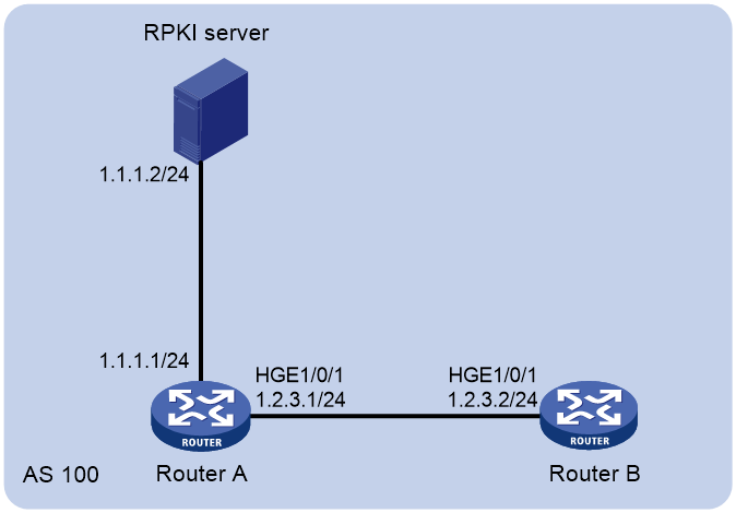
Procedure
|
|
NOTE: By default, interfaces on the device are disabled (in ADM or Administratively Down state). To have an interface operate, you must use the undo shutdown command to enable that interface. |
1. Configure IP addresses for interfaces and establish an IBGP connection between Router A and Router B. (Details not shown.)
2. Configure Router A to establish a TCP connection to the RPKI server.
<RouterA> system-view
[RouterA] bgp 100
[RouterA-bgp-default] rpki
[RouterA-bgp-default-rpki] server tcp 1.1.1.2
[RouterA-bgp-default-rpki-server] port 1234
[RouterA-bgp-default-rpki-server] quit
3. Enable BGP RPKI validation on Router A.
[RouterA-bgp-default-rpki] check-origin-validation
[RouterA-bgp-default-rpki] quit
4. Apply the BGP RPKI validation state to optimal route selection.
[RouterA-bgp-default] address-family ipv4
[RouterA-bgp-default-ipv4] bestroute origin-as-validation
5. Configure Router A to advertise the BGP RPKI validation state to peer 1.2.3.2.
[RouterA-bgp-default-ipv4] peer 1.2.3.2 advertise-ext-community
[RouterA-bgp-default-ipv4] peer 1.2.3.2 advertise origin-as-validation
[RouterA-bgp-default-ipv4] quit
[RouterA-bgp-default] quit
6. Configure Router B to permit routes with a BGP RPKI validation state of Valid.
# Configure a routing policy.
<RouterB> system-view
[RouterB] route-policy rpki_policy permit node 0
[RouterB-route-policy-rpki_policy-0] if-match rpki valid
[RouterB-route-policy-rpki_policy-0] quit
# Apply the routing policy.
[RouterB] bgp 100
[RouterB-bgp-default] address-family ipv4
[RouterB-bgp-default-ipv4] peer 1.2.3.1 route-policy rpki_policy import
Verifying the configuration
# Display information about the connection between Router A and the RPKI server.
[RouterA] display bgp rpki server
Server VPN-index Port State Time ROAs(IPv4/IPv6)
1.1.1.2 0 1234 Establish 00:04:43 5/4
The output shows that Router A has established a TCP connection to the RPKI server.
# Display the ROA information on Router A.
[RouterA] display bgp rpki table ipv4
Total number of entries: 5
Status codes: S - stale, U - used
Network Mask-range Origin-AS Server Status
1.2.3.4 8-24 100 1.1.1.2 U
2.2.3.6 8-32 100 1.1.1.2 U
2.2.3.6 10-24 4294967295 1.1.1.2 U
2.2.3.9 20-24 4294967295 1.1.1.2 U
3.2.3.5 8-26 200 1.1.1.2 U
The output shows that Router A has obtained the ROA information from the RPKI server.
# Display the BGP RPKI validation state on Router A.
[RouterA] display bgp routing-table ipv4 1.2.3.0
BGP local router ID: 2.2.2.2
Local AS number: 100
Paths: 1 available, 1 best
BGP routing table information of 1.2.3.0/24:
Imported route.
Original nexthop: 0.0.0.0
OutLabel : NULL
RxPathID : 0x0
TxPathID : 0x0
Org-validation : Valid
AS-path : (null)
Origin : incomplete
Attribute value : MED 0, pref-val 32768
State : valid, local, best
IP precedence : N/A
QoS local ID : N/A
Traffic index : N/A
The route to 1.2.3.0 matches the ROA with a prefix of 1.2.3.4, a mask length range of 8 to 24, and an origin AS number of 100. Therefore, the BGP RPKI validation state of the route to 1.2.3.0 is Valid.
# On Router B, display detailed information about the BGP IPv4 unicast route to 1.2.3.0.
[RouterB] display bgp routing-table ipv4 1.2.3.0
RR-client route.
From : 1.2.3.1 (192.168.56.22)
Rely nexthop : 1.2.3.1
Original nexthop: 1.2.3.1
OutLabel : NULL
Ext-Community : <Origin Valid State: Valid >
RxPathID : 0x0
TxPathID : 0x0
Org-validation : Valid
AS-path : (null)
Origin : incomplete
Attribute value : MED 0, localpref 100, pref-val 0
State : valid, internal, best
IP precedence : N/A
QoS local ID : N/A
Traffic index : N/A
The output displays information about the BGP IPv4 unicast route to 1.2.3.0 because Router B permits routes with a BGP RPKI validation state of Valid.
IPv6 BGP security feature configuration examples
Example: Configuring BGP RPKI
Network configuration
As shown in Figure 5, all routers run IPv6 BGP. Establish a TCP connection between Router A and the RPKI server, and establish an IBGP connection between Router A and Router B.
Configure Router A to advertise the BGP RPKI validation state to Router B, and configure a routing policy to filter routes based on the validation state for Router B.
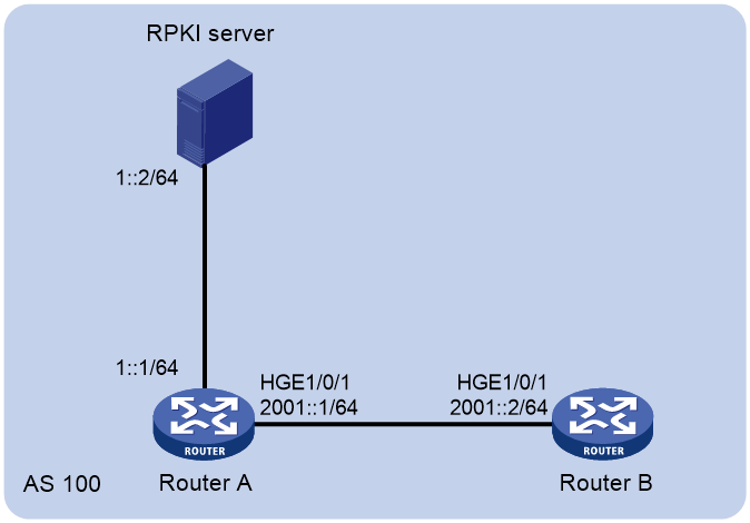
Procedure
|
|
NOTE: By default, interfaces on the device are disabled (in ADM or Administratively Down state). To have an interface operate, you must use the undo shutdown command to enable that interface. |
1. Configure IPv6 addresses for interfaces and establish an IBGP connection between Router A and Router B. (Details not shown.)
2. Configure Router A to establish a TCP connection to the RPKI server.
<RouterA> system-view
[RouterA] bgp 100
[RouterA-bgp-default] rpki
[RouterA-bgp-default-rpki] server tcp 1::2
[RouterA-bgp-default-rpki-server] port 1234
[RouterA-bgp-default-rpki-server] quit
3. Enable BGP RPKI validation on Router A.
[RouterA-bgp-default-rpki] check-origin-validation
[RouterA-bgp-default-rpki] quit
4. Apply the BGP RPKI validation state to optimal route selection.
[RouterA-bgp-default] address-family ipv6
[RouterA-bgp-default-ipv6] bestroute origin-as-validation
5. Configure Router A to advertise the BGP RPKI validation state to peer 2001::2.
[RouterA-bgp-default-ipv6] peer 2001::2 advertise-ext-community
[RouterA-bgp-default-ipv6] peer 2001::2 advertise origin-as-validation
[SwitchA-bgp-default-ipv6] quit
[SwitchA-bgp-default] quit
6. Configure Router B to permit routes with a BGP RPKI validation state of Valid:
# Configure a routing policy.
<RouterB> system-view
[RouterB] route-policy rpki_policy permit node 0
[RouterB-route-policy-rpki_policy-0] if-match rpki valid
# Apply the routing policy.
<RouterB> system-view
[RouterB] bgp 100
[RouterB-bgp-default] address-family ipv6
[RouterB-bgp-default-ipv6] peer 2001::1 route-policy rpki_policy import
Verifying the configuration
# Display information about the connection between Router A and the RPKI server.
[RouterA] display bgp rpki server
Server VPN-index Port State Time ROAs(IPv4/IPv6)
1::2 0 1234 Establish 00:04:43 5/5
The output shows that Router A has established a TCP connection to the RPKI server.
# Display the ROA information on Router A.
[RouterA] display bgp rpki table ipv6
Total number of entries: 5
Status codes: S - stale, U - used
Network Mask-range Origin-AS Server Status
2001:4860:: 32-32 100 1::2 U
2404:6800:: 32-32 100 1::2 U
2607:F8B0:: 28-28 4294967295 1::2 U
2A03:ACE0:: 40-40 4294967295 1::2 U
2001::1 64-64 200 1::2 U
The output shows that Router A has obtained the ROA information from the RPKI server.
# Display the BGP RPKI validation state on Router A.
[RouterA] display bgp routing-table ipv6 2001::1 64
BGP local router ID: 2.2.2.2
Local AS number: 100
Paths: 1 available, 1 best
BGP routing table information of 2001::1/64:
Imported route.
Original nexthop: 0.0.0.0
OutLabel : NULL
RxPathID : 0x0
TxPathID : 0x0
Org-validation : Valid
AS-path : (null)
Origin : incomplete
Attribute value : MED 0, pref-val 32768
State : valid, local, best
IP precedence : N/A
QoS local ID : N/A
The route to 2001::1 matches the ROA with a prefix of 2001::1, a prefix length range of 64 to 64, and an origin AS number of 200. Therefore, the BGP RPKI validation state of the route to 2001::1 is Valid.
# On Router B, display detailed information about the BGP IPv6 unicast route to 2001::1.
[RouterB] display bgp routing-table ipv6 2001::1 64
RR-client route.
From : 2001::1 64 (192.168.56.22)
Rely nexthop : 2001::1
Original nexthop: 2001::1
OutLabel : NULL
Ext-Community : <Origin Valid State: Valid >
RxPathID : 0x0
TxPathID : 0x0
Org-validation : Invalid
AS-path : (null)
Origin : incomplete
Attribute value : MED 0, localpref 100, pref-val 0
State : valid, internal, best
IP precedence : N/A
QoS local ID : N/A
Traffic index : N/A
The output displays information about the BGP IPv6 unicast route to 2001::1 because Router B permits routes with a BGP RPKI validation state of Valid.
Improving BGP network reliability
BGP network reliability improvement tasks at a glance
To improve the BGP network reliability, perform the following tasks:
Configuring BGP GR
About this task
Graceful Restart (GR) ensures forwarding continuous when a routing protocol restarts or an active/standby switchover occurs. Two routers are required to complete a GR process. The following are router roles in a GR process:
· GR restarter—Performs GR upon a BGP restart or active/standby switchover.
· GR helper—Helps the GR restarter to complete the GR process.
A device can act as a GR restarter and GR helper at the same time.
BGP GR works as follows:
1. The BGP GR restarter and helper exchange OPEN messages for GR capability negotiation. If both parties have the GR capability, they establish a GR-capable session. The GR restarter sends the GR timer set by the graceful-restart timer restart command to the GR helper in an OPEN message.
2. When an active/standby switchover occurs or BGP restarts, the GR restarter does not remove existing BGP routes from Routing Information Base (RIB) and Forwarding Information Base (FIB). It still uses these routes for packet forwarding, and it starts the RIB purge timer (set by the graceful-restart timer purge-time command). The GR helper marks all routes learned from the GR restarter as stale instead of deleting them. It continues to use these routes for packet forwarding. During the GR process, packet forwarding is not interrupted.
3. After the active/standby switchover or BGP restart completes, the GR restarter re-establishes a BGP session to the GR helper. If the BGP session fails to be established after both the GR timer and the extra timer to wait expire, the GR helper removes the stale routes. To set the extra timer to wait after the restart timer expires, execute the peer graceful-restart timer restart extra command.
4. If the BGP session is established, routing information is exchanged for the GR restarter to retrieve route entries and for the GR helper to recover stale routes.
5. Both the GR restarter and the GR helper start the End-Of-RIB marker waiting timer.
The End-Of-RIB marker waiting time is set by the graceful-restart timer wait-for-rib command. If routing information exchange is not completed within the time, the GR restarter does not receive new routes. The GR restarter updates the RIB with the BGP routes already learned, and removes the aged routes from the RIB. The GR helper removes the stale routes.
6. The GR restarter quits the GR process if routing information exchange is not completed within the RIB purge timer. It updates the RIB with the BGP routes already learned, and removes the aged routes.
When the TCP connection goes down, the hold timer expires, or the support for a new address family is added, BGP tears down and then re-establishes the peer sessions, which will cause traffic interruption. To avoid traffic interruption in these cases, enable BGP to reset peer sessions gracefully.
Restrictions and guidelines
Follow these guidelines when you configure BGP GR:
· The End-Of-RIB indicates the end of route updates.
· The maximum time to wait for the End-of-RIB marker configured on the local end is not advertised to the peer. It controls the time for the local end to receive updates from the peer. Set a large value for the maximum time to wait for the End-of-RIB marker when a large number of routes need to be exchanged.
· As a best practice, perform the BGP GR configuration on both the GR restarter and GR helper.
Procedure
1. Enter system view.
system-view
2. Enter BGP instance view.
bgp as-number [ instance instance-name ]
3. Enable GR capability for BGP.
graceful-restart
By default, GR capability is disabled for BGP.
4. Configure the GR timer.
graceful-restart timer restart timer
The default setting is 150 seconds.
The time that a peer waits to re-establish a session must be less than the hold time.
5. (Optional.) Set the extra time to wait after the restart timer expires.
peer { group-name | ipv4-address [ mask-length ] | ipv6-address [ prefix-length ] } graceful-restart timer restart extra { time | no-limit }
By default, the extra time to wait after the restart timer expires is 0 seconds.
6. Configure the maximum time to wait for the End-of-RIB marker.
graceful-restart timer wait-for-rib timer
The default setting is 600 seconds.
7. Configure the RIB purge timer.
graceful-restart timer purge-time timer
The default setting is 480 seconds.
8. (Optional.) Enable BGP to reset peer sessions gracefully.
graceful-restart peer-reset [ all ]
By default, BGP does not reset peer sessions gracefully.
9. (Optional.) Configure the time that BGP must wait for other protocols to complete GR after BGP completes GR.
bgp update-delay wait-other-protocol seconds
By default, after BGP completes GR, it must wait a maximum of 300 seconds for other protocols to complete GR.
Configuring BGP NSR
About this task
To use BGP nonstop routing (NSR), the system must have a minimum of two MPUs.
NSR ensures nonstop services when BGP has redundant processes on multiple MPUs. In contrast to GR, NSR does not require a neighbor device to recover routing information.
BGP NSR backs up BGP state and data information from the active BGP process to the standby BGP process. The standby BGP process takes over when any of the following events occurs:
· The active BGP process restarts.
· The MPU that runs the active BGP process fails.
Restrictions and guidelines
When both GR and NSR are configured for BGP, NSR has a higher priority than GR. The device will not act as the GR restarter. If the device acts as a GR helper, it cannot help the restarter to complete GR.
To use BGP NSR in MPLS L3VPN, you must enable RIB NSR. For information about RIB NSR, see "Configuring basic IP routing."
Procedure
1. Enter system view.
system-view
2. Enter BGP instance view.
bgp as-number [ instance instance-name ]
3. Enable BGP NSR.
non-stop-routing
By default, BGP NSR is disabled.
4. (Optional.) Configure the time that BGP must wait for other protocols to complete NSR after BGP completes NSR.
bgp update-delay wait-other-protocol seconds
By default, after BGP completes NSR, it must wait a maximum of 300 seconds for other protocols to complete NSR.
Verifying and maintaining BGP NSR
To display BGP NSR status information, execute the following command in any view:
display bgp [ instance instance-name ] non-stop-routing status
Configuring BFD for BGP
About this task
BGP maintains neighbor relationships based on the keepalive timer and hold timer in seconds. It requires that the hold time must be at least three times the keepalive interval. This mechanism slows down link failure detection. Once a failure occurs on a high-speed link, a large quantity of packets will be dropped before routing convergence completes. BFD for BGP can solve this problem by fast detecting link failures to reduce convergence time.
Before you enable BFD for a BGP peer or peer group, you must establish a BGP session between the local router and the peer or peer group.
For more information about BFD, see High Availability Configuration Guide.
Restrictions and guidelines
If you have enabled GR, use BFD with caution because BFD might detect a failure before the system performs GR, which will result in GR failure. If you have enabled both BFD and GR for BGP, do not disable BFD during a GR process to avoid GR failure.
Procedure (IPv4 peers)
1. Enter system view.
system-view
2. Enter BGP instance view or BGP-VPN instance view.
¡ Enter BGP instance view.
bgp as-number [ instance instance-name ]
¡ Enter BGP-VPN instance view.
bgp as-number [ instance instance-name ]
ip vpn-instance vpn-instance-name
3. Enable BFD to detect the link to the specified BGP peer or peer group.
peer { group-name | ipv4-address [ mask-length ] } bfd [ echo | multi-hop | single-hop ]
By default, BFD is disabled.
Procedure (IPv6 peers)
1. Enter system view.
system-view
2. Enter BGP instance view or BGP-VPN instance view.
¡ Enter BGP instance view.
bgp as-number [ instance instance-name ]
¡ Enter BGP-VPN instance view.
bgp as-number [ instance instance-name ]
ip vpn-instance vpn-instance-name
3. Enable BFD to detect the link to the specified IPv6 BGP peer or peer group.
peer { group-name | ipv6-address [ prefix-length ] } bfd [ echo | multi-hop | single-hop ]
By default, BFD is disabled.
Configuring BGP FRR
About BGP FRR
When a link fails, the packets on the link are discarded, and a routing loop might occur until BGP completes routing convergence based on the new network topology.
You can enable BGP fast reroute (FRR) to resolve this issue.
Figure 6 Network diagram for BGP FRR
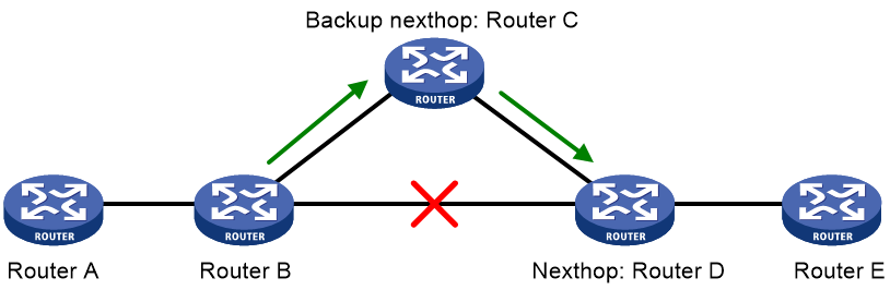
After you configure FRR on Router B as shown in Figure 6, BGP generates a backup next hop Router C for the primary route. BGP uses ARP or BFD echo packet mode in an IPv4 network or ND in an IPv6 network to detect the connectivity to Router D. When the link to Router D fails, BGP directs packets to the backup next hop. At the same time, BGP calculates a new optimal route, and forwards packets over the optimal route.
You can use the following methods to configure BGP FRR:
· Method 1—Execute the pic command in BGP address family view. BGP calculates a backup next hop for each BGP route in the address family if there are two or more unequal-cost routes that reach the destination.
· Method 2—Execute the fast-reroute route-policy command to use a routing policy in which a backup next hop is specified by using the command apply [ ipv6 ] fast-reroute backup-nexthop. The backup next hop calculated by BGP must be the same as the specified backup next hop. Otherwise, BGP does not generate a backup next hop for the primary route. You can also configure if-match clauses in the routing policy to identify the routes protected by FRR.
If both methods are configured, Method 2 takes precedence over Method 1.
BGP supports FRR for IPv4 and IPv6 unicast routes.
Configuring BGP FRR by using a routing policy (IPv4 unicast address family)
1. Enter system view.
system-view
2. Configure the source address of echo packets.
bfd echo-source-ip ipv4-address
By default, no source address is specified for echo packets.
This step is required when BFD echo packet mode is used to detect the connectivity to the next hop of the primary route.
Specify a source IP address that does not belong to any local network.
For more information about this command, see BFD commands in High Availability Command Reference.
3. Create a routing policy and enter routing policy view.
route-policy route-policy-name permit node node-number
For more information about this command, see routing policy commands in Layer 3—IP Routing Command Reference.
4. Set the backup next hop for FRR.
apply fast-reroute backup-nexthop ipv4-address
By default, no backup next hop is set.
For more information about this command, see routing policy commands in Layer 3—IP Routing Command Reference.
5. Return to system view.
quit
6. Enter BGP instance view.
bgp as-number [ instance instance-name ]
7. (Optional.) Use echo mode BFD to detect the connectivity to the next hop of the primary route.
primary-path-detect bfd { ctrl | echo }
By default, ARP is used to detect the connectivity to the next hop.
8. Enter BGP IPv4 unicast address family view or BGP-VPN IPv4 unicast address family view.
¡ Enter BGP IPv4 unicast address family view.
address-family ipv4 [ unicast ]
¡ Enter BGP-VPN IPv4 unicast address family view.
ip vpn-instance vpn-instance-name
address-family ipv4 [ unicast ]
9. Apply a routing policy to FRR for the address family.
fast-reroute route-policy route-policy-name
By default, no routing policy is applied.
The apply fast-reroute backup-nexthop command and apply ipv6 fast-reroute backup-nexthop command can take effect in the applied routing policy. Other apply commands do not take effect.
Configuring BGP FRR by using a routing policy (IPv6 unicast address family)
1. Enter system view.
system-view
2. Create a routing policy and enter routing policy view.
route-policy route-policy-name permit node node-number
For more information about this command, see routing policy commands in Layer 3—IP Routing Command Reference.
3. Set the backup next hop for FRR.
apply ipv6 fast-reroute backup-nexthop ipv6-address
By default, no backup next hop is set.
For more information about this command, see routing policy commands in Layer 3—IP Routing Command Reference.
4. Return to system view.
quit
5. Enter BGP instance view or BGP-VPN instance view.
¡ Enter BGP instance view.
bgp as-number [ instance instance-name ]
¡ Enter BGP-VPN instance view.
bgp as-number [ instance instance-name ]
ip vpn-instance vpn-instance-name
6. Enter BGP IPv6 unicast address family view or BGP-VPN IPv6 unicast address family view.
address-family ipv6 [ unicast ]
7. Apply a routing policy to FRR for the address family.
fast-reroute route-policy route-policy-name
By default, no routing policy is applied.
The apply fast-reroute backup-nexthop and apply ipv6 fast-reroute backup-nexthop commands can take effect in the applied routing policy. Other apply commands do not take effect.
Configuring BGP FRR through PIC (IPv4 unicast address family)
Restrictions and guidelines
This feature might result in routing loops. Use it with caution.
Procedure
1. Enter system view.
system-view
2. Enter BGP instance view or BGP-VPN instance view.
¡ Enter BGP instance view.
bgp as-number [ instance instance-name ]
¡ Enter BGP-VPN instance view.
bgp as-number [ instance instance-name ]
ip vpn-instance vpn-instance-name
3. Enter BGP IPv4 unicast address family view or BGP-VPN IPv4 unicast address family view.
address-family ipv4 [ unicast ]
4. Enable BGP FRR through PIC.
pic
By default, BGP FRR is disabled.
Configuring BGP FRR through PIC (IPv6 unicast address family)
Restrictions and guidelines
This feature might result in routing loops. Use it with caution.
Procedure
1. Enter system view.
system-view
2. Enter BGP instance view or BGP-VPN instance view.
¡ Enter BGP instance view.
bgp as-number [ instance instance-name ]
¡ Enter BGP-VPN instance view.
bgp as-number [ instance instance-name ]
ip vpn-instance vpn-instance-name
3. Enter BGP IPv6 unicast address family view or BGP-VPN IPv6 unicast address family view.
address-family ipv6 [ unicast ]
4. Enable BGP FRR through PIC.
pic
By default, BGP FRR is disabled.
IPv4 BGP network reliability improvement configuration examples
Example: Configuring BGP GR
Network configuration
As shown in Figure 7, run EBGP between Router A and Router B, and run IBGP between Router B and Router C.
Configure BGP GR so that the communication between Router A and Router C is not affected when an active/standby switchover occurs on Router B.
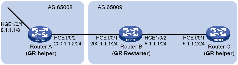
Procedure
|
|
NOTE: By default, interfaces on the device are disabled (in ADM or Administratively Down state). To have an interface operate, you must use the undo shutdown command to enable that interface. |
1. Configure Router A:
# Configure IP addresses for interfaces. (Details not shown.)
# Configure the EBGP connection.
<RouterA> system-view
[RouterA] bgp 65008
[RouterA-bgp-default] router-id 1.1.1.1
[RouterA-bgp-default] peer 200.1.1.1 as-number 65009
# Enable GR capability for BGP.
[RouterA-bgp-default] graceful-restart
# Inject network 8.0.0.0/8 to the IPv4 BGP routing table.
[RouterA-bgp-default] address-family ipv4
[RouterA-bgp-default-ipv4] network 8.0.0.0
# Enable Router A to exchange IPv4 unicast routing information with Router B.
[RouterA-bgp-default-ipv4] peer 200.1.1.1 enable
2. Configure Router B:
# Configure IP addresses for interfaces. (Details not shown.)
# Configure the EBGP connection.
<RouterB> system-view
[RouterB] bgp 65009
[RouterB-bgp-default] router-id 2.2.2.2
[RouterB-bgp-default] peer 200.1.1.2 as-number 65008
# Configure the IBGP connection.
[RouterB-bgp-default] peer 9.1.1.2 as-number 65009
# Enable GR capability for BGP.
[RouterB-bgp-default] graceful-restart
# Inject networks 200.1.1.0/24 and 9.1.1.0/24 to the IPv4 BGP routing table.
[RouterB-bgp-default] address-family ipv4
[RouterB-bgp-default-ipv4] network 200.1.1.0 24
[RouterB-bgp-default-ipv4] network 9.1.1.0 24
# Enable Router B to exchange IPv4 unicast routing information with Router A and Router C.
[RouterB-bgp-default-ipv4] peer 200.1.1.2 enable
[RouterB-bgp-default-ipv4] peer 9.1.1.2 enable
3. Configure Router C:
# Configure IP addresses for interfaces. (Details not shown.)
# Configure the IBGP connection.
<RouterC> system-view
[RouterC] bgp 65009
[RouterC-bgp-default] router-id 3.3.3.3
[RouterC-bgp-default] peer 9.1.1.1 as-number 65009
# Enable GR capability for BGP.
[RouterC-bgp-default] graceful-restart
# Enable Router C to exchange IPv4 unicast routing information with Router B.
[RouterC-bgp-default] address-family ipv4
[RouterC-bgp-default-ipv4] peer 9.1.1.1 enable
Verifying the configuration
Ping Router C on Router A. Meanwhile, perform an active/standby switchover on Router B. The ping operation is successful during the whole switchover process. (Details not shown.)
Example: Configuring BFD for BGP
Network configuration
As shown in Figure 8, configure OSPF as the IGP in AS 200.
· Establish two IBGP connections between Router A and Router C. When both paths operate correctly, Router C uses the path Router A<—>Router B<—>Router C to communicate with network 1.1.1.0/24.
· Configure BFD over the path. When the path fails, BFD can quickly detect the failure and notify it to BGP. Then, the path Router A<—>Router D<—>Router C takes effect immediately.
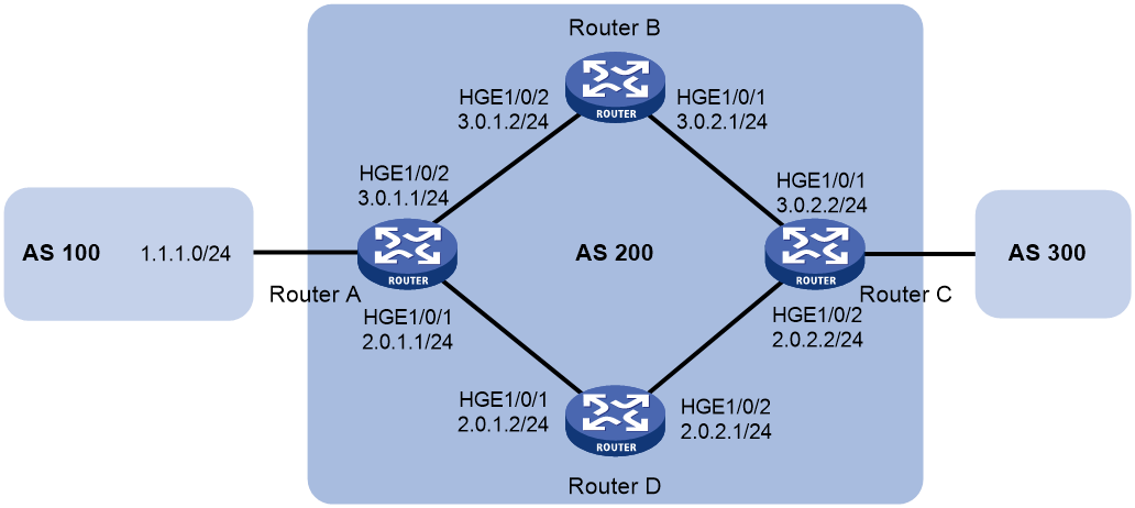
Procedure
|
|
NOTE: By default, interfaces on the device are disabled (in ADM or Administratively Down state). To have an interface operate, you must use the undo shutdown command to enable that interface. |
1. Configure IP addresses for interfaces. (Details not shown.)
2. Configure OSPF so that Router A and Router C can reach each other. (Details not shown.)
3. Configure BGP on Router A:
# Establish two IBGP connections to Router C.
<RouterA> system-view
[RouterA] bgp 200
[RouterA-bgp-default] peer 3.0.2.2 as-number 200
[RouterA-bgp-default] peer 2.0.2.2 as-number 200
[RouterA-bgp-default] address-family ipv4 unicast
[RouterA-bgp-default-ipv4] peer 3.0.2.2 enable
[RouterA-bgp-default-ipv4] peer 2.0.2.2 enable
[RouterA-bgp-default-ipv4] quit
# Create IPv4 basic ACL 2000 to permit 1.1.1.0/24 to pass.
[RouterA] acl basic 2000
[RouterA-acl-ipv4-basic-2000] rule permit source 1.1.1.0 0.0.0.255
[RouterA-acl-ipv4-basic-2000] quit
# Create two routing policies to set the MED for route 1.1.1.0/24. The policy apply_med_50 sets the MED to 50, and the policy apply_med_100 sets the MED to 100.
[RouterA] route-policy apply_med_50 permit node 10
[RouterA-route-policy-apply_med_50-10] if-match ip address acl 2000
[RouterA-route-policy-apply_med_50-10] apply cost 50
[RouterA-route-policy-apply_med_50-10] quit
[RouterA] route-policy apply_med_100 permit node 10
[RouterA-route-policy-apply_med_100-10] if-match ip address acl 2000
[RouterA-route-policy-apply_med_100-10] apply cost 100
[RouterA-route-policy-apply_med_100-10] quit
# Apply routing policy apply_med_50 to routes outgoing to peer 3.0.2.2, and apply routing policy apply_med_100 to routes outgoing to peer 2.0.2.2.
[RouterA] bgp 200
[RouterA-bgp-default] address-family ipv4 unicast
[RouterA-bgp-default-ipv4] peer 3.0.2.2 route-policy apply_med_50 export
[RouterA-bgp-default-ipv4] peer 2.0.2.2 route-policy apply_med_100 export
[RouterA-bgp-default-ipv4] quit
# Enable BFD for peer 3.0.2.2.
[RouterA-bgp-default] peer 3.0.2.2 bfd
[RouterA-bgp-default] quit
4. Configure BGP on Router C:
# Establish two IBGP connections to Router A.
<RouterC> system-view
[RouterC] bgp 200
[RouterC-bgp-default] peer 3.0.1.1 as-number 200
[RouterC-bgp-default] peer 2.0.1.1 as-number 200
[RouterC-bgp-default] address-family ipv4 unicast
[RouterC-bgp-default-ipv4] peer 3.0.1.1 enable
[RouterC-bgp-default-ipv4] peer 2.0.1.1 enable
[RouterC-bgp-default-ipv4] quit
# Enable BFD for peer 3.0.1.1.
[RouterC-bgp-default] peer 3.0.1.1 bfd
[RouterC-bgp-default] quit
[RouterC] quit
Verifying the configuration
# Display detailed BFD session information on Router C.
<RouterC> display bfd session verbose
Total Session Num: 1 Up Session Num: 1 Init Mode: Active
IPv4 Session Working in control packet mode:
Local Discr: 513 Remote Discr: 513
Source IP: 3.0.2.2 Destination IP: 3.0.1.1
Session State: Up Interface: N/A
Min Tx Inter: 500ms Act Tx Inter: 500ms
Min Rx Inter: 500ms Detect Inter: 2500ms
Rx Count: 135 Tx Count: 135
Connect Type: Indirect Running Up for: 00:00:58
Hold Time: 2457ms Auth mode: None
Detect Mode: Async Slot: 0
Protocol: BGP
Version:1
Diag Info: No Diagnostic
The output shows that a BFD session has been established between Router A and Router C.
# Display BGP peer information on Router C.
<RouterC> display bgp peer ipv4
BGP local router ID: 3.3.3.3
Local AS number: 200
Total number of peers: 2 Peers in established state: 2
* - Dynamically created peer
Peer AS MsgRcvd MsgSent OutQ PrefRcv Up/Down State
2.0.1.1 200 4 5 0 0 00:01:55 Established
3.0.1.1 200 4 5 0 0 00:01:52 Established
The output shows that Router C has established two BGP connections with Router A, and both connections are in Established state.
# Display route 1.1.1.0/24 on Router C.
<RouterC> display ip routing-table 1.1.1.0 24 verbose
Summary count : 1
Destination: 1.1.1.0/24
Protocol: BGP Process ID: 0
SubProtID: 0x1 Age: 00h00m09s
Cost: 50 Preference: 255
IpPre: N/A QosLocalID: N/A
Tag: 0 State: Active Adv
OrigTblID: 0x1 OrigVrf: default-vrf
TableID: 0x2 OrigAs: 0
NibID: 0x15000001 LastAs: 0
AttrID: 0x1 Neighbor: 3.0.1.1
Flags: 0x10060 OrigNextHop: 3.0.1.1
Label: NULL RealNextHop: 3.0.2.1
BkLabel: NULL BkNextHop: N/A
SRLabel: NULL BKSRLabel: NULL
SIDIndex: NULL InLabel: NULL
Tunnel ID: Invalid Interface: HundredGigE1/0/1
BkTunnel ID: Invalid BkInterface: N/A
FtnIndex: 0x0 TrafficIndex: N/A
Connector: N/A PathID: 0x0
SRTunnelID: Invalid
SID Type: N/A Exp: N/A
VpnPeerId: N/A Dscp: N/A
The output shows that Router C communicates with network 1.1.1.0/24 through the path Router C<—>Router B<—>Router A.
# Break down the link Router C<—>Router B<—>Router A and then display route 1.1.1.0/24 on Router C.
<RouterC> display ip routing-table 1.1.1.0 24 verbose
Summary count : 1
Destination: 1.1.1.0/24
Protocol: BGP Process ID: 0
SubProtID: 0x1 Age: 00h03m08s
Cost: 100 Preference: 255
IpPre: N/A QosLocalID: N/A
Tag: 0 State: Active Adv
OrigTblID: 0x1 OrigVrf: default-vrf
TableID: 0x2 OrigAs: 0
NibID: 0x15000000 LastAs: 0
AttrID: 0x0 Neighbor: 2.0.1.1
Flags: 0x10060 OrigNextHop: 2.0.1.1
Label: NULL RealNextHop: 2.0.2.1
BkLabel: NULL BkNextHop: N/A
SRLabel: NULL BKSRLabel: NULL
SIDIndex: NULL InLabel: NULL
Tunnel ID: Invalid Interface: HundredGigE1/0/2
BkTunnel ID: Invalid BkInterface: N/A
FtnIndex: 0x0 TrafficIndex: N/A
Connector: N/A PathID: 0x0
SRTunnelID: Invalid
SID Type: N/A Exp: N/A
VpnPeerId: N/A Dscp: N/A
The output shows that Router C communicates with network 1.1.1.0/24 through the path Router C<—>Router D<—>Router A.
Example: Configuring BGP FRR
Network configuration
As shown in Figure 9, configure BGP FRR so that when Link B fails, BGP uses Link A to forward traffic.

Procedure
|
|
NOTE: By default, interfaces on the device are disabled (in ADM or Administratively Down state). To have an interface operate, you must use the undo shutdown command to enable that interface. |
1. Configure IP addresses for interfaces. (Details not shown.)
2. Configure OSPF in AS 200 to ensure connectivity among Router B, Router C, and Router D. (Details not shown.)
3. Configure BGP connections:
# Configure Router A to establish EBGP sessions to Router B and Router C, and advertise network 1.1.1.1/32.
<RouterA> system-view
[RouterA] bgp 100
[RouterA-bgp-default] router-id 1.1.1.1
[RouterA-bgp-default] peer 10.1.1.2 as-number 200
[RouterA-bgp-default] peer 30.1.1.3 as-number 200
[RouterA-bgp-default] address-family ipv4 unicast
[RouterA-bgp-default-ipv4] peer 10.1.1.2 enable
[RouterA-bgp-default-ipv4] peer 30.1.1.3 enable
[RouterA-bgp-default-ipv4] network 1.1.1.1 32
# Configure Router B to establish an EBGP session to Router A, and an IBGP session to Router D.
<RouterB> system-view
[RouterB] bgp 200
[RouterB-bgp-default] router-id 2.2.2.2
[RouterB-bgp-default] peer 10.1.1.1 as-number 100
[RouterB-bgp-default] peer 4.4.4.4 as-number 200
[RouterB-bgp-default] peer 4.4.4.4 connect-interface loopback 0
[RouterB-bgp-default] address-family ipv4 unicast
[RouterB-bgp-default-ipv4] peer 10.1.1.1 enable
[RouterB-bgp-default-ipv4] peer 4.4.4.4 enable
[RouterB-bgp-default-ipv4] peer 4.4.4.4 next-hop-local
[RouterB-bgp-default-ipv4] quit
[RouterB-bgp-default] quit
# Configure Router C to establish an EBGP session to Router A, and an IBGP session to Router D.
<RouterC> system-view
[RouterC] bgp 200
[RouterC-bgp-default] router-id 3.3.3.3
[RouterC-bgp-default] peer 30.1.1.1 as-number 100
[RouterC-bgp-default] peer 4.4.4.4 as-number 200
[RouterC-bgp-default] peer 4.4.4.4 connect-interface loopback 0
[RouterC-bgp-default] address-family ipv4 unicast
[RouterC-bgp-default-ipv4] peer 30.1.1.1 enable
[RouterC-bgp-default-ipv4] peer 4.4.4.4 enable
[RouterC-bgp-default-ipv4] peer 4.4.4.4 next-hop-local
[RouterC-bgp-default-ipv4] quit
[RouterC-bgp-default] quit
# Configure Router D to establish IBGP sessions to Router B and Router C, and advertise network 4.4.4.4/32.
<RouterD> system-view
[RouterD] bgp 200
[RouterD-bgp-default] router-id 4.4.4.4
[RouterD-bgp-default] peer 2.2.2.2 as-number 200
[RouterD-bgp-default] peer 2.2.2.2 connect-interface loopback 0
[RouterD-bgp-default] peer 3.3.3.3 as-number 200
[RouterD-bgp-default] peer 3.3.3.3 connect-interface loopback 0
[RouterD-bgp-default] address-family ipv4 unicast
[RouterD-bgp-default-ipv4] peer 2.2.2.2 enable
[RouterD-bgp-default-ipv4] peer 3.3.3.3 enable
[RouterD-bgp-default-ipv4] network 4.4.4.4 32
4. Configure preferred values so Link B is used to forward traffic between Router A and Router D:
# Configure Router A to set the preferred value to 100 for routes received from Router B.
[RouterA-bgp-default-ipv4] peer 10.1.1.2 preferred-value 100
[RouterA-bgp-default-ipv4] quit
[RouterA-bgp-default] quit
# Configure Router D to set the preferred value to 100 for routes received from Router B.
[RouterD-bgp-default-ipv4] peer 2.2.2.2 preferred-value 100
[RouterD-bgp-default-ipv4] quit
[RouterD-bgp-default] quit
5. Configure BGP FRR:
# On Router A, configure the source address of BFD echo packets as 11.1.1.1.
[RouterA] bfd echo-source-ip 11.1.1.1
# Create routing policy frr to set a backup next hop 30.1.1.3 (Router C) for the route destined for 4.4.4.4/32.
[RouterA] ip prefix-list abc index 10 permit 4.4.4.4 32
[RouterA] route-policy frr permit node 10
[RouterA-route-policy] if-match ip address prefix-list abc
[RouterA-route-policy] apply fast-reroute backup-nexthop 30.1.1.3
[RouterA-route-policy] quit
# Use BFD echo packet mode to detect the connectivity to Router D.
[RouterA] bgp 100
[RouterA-bgp-default] primary-path-detect bfd echo
# Apply the routing policy to BGP FRR for BGP IPv4 unicast address family.
[RouterA-bgp-default] address-family ipv4 unicast
[RouterA-bgp-default-ipv4] fast-reroute route-policy frr
[RouterA-bgp-default-ipv4] quit
[RouterA-bgp-default] quit
# On Router D, set the source address of BFD echo packets to 44.1.1.1.
[RouterD] bfd echo-source-ip 44.1.1.1
# Create routing policy frr to set a backup next hop 3.3.3.3 (Router C) for the route destined for 1.1.1.1/32.
[RouterD] ip prefix-list abc index 10 permit 1.1.1.1 32
[RouterD] route-policy frr permit node 10
[RouterD-route-policy] if-match ip address prefix-list abc
[RouterD-route-policy] apply fast-reroute backup-nexthop 3.3.3.3
[RouterD-route-policy] quit
# Use BFD echo packet mode to detect the connectivity to Router A.
[RouterD] bgp 200
[RouterD-bgp-default] primary-path-detect bfd echo
# Apply the routing policy to BGP FRR for BGP IPv4 unicast address family.
[RouterD-bgp-default] address-family ipv4 unicast
[RouterD-bgp-default-ipv4] fast-reroute route-policy frr
[RouterD-bgp-default-ipv4] quit
[RouterD-bgp-default] quit
Verifying the configuration
# Display detailed information about the route to 4.4.4.4/32 on Router A. The output shows the backup next hop for the route.
[RouterA] display ip routing-table 4.4.4.4 32 verbose
Summary count : 1
Destination: 4.4.4.4/32
Protocol: BGP Process ID: 0
SubProtID: 0x2 Age: 00h01m52s
Cost: 0 Preference: 255
IpPre: N/A QosLocalID: N/A
Tag: 0 State: Active Adv
OrigTblID: 0x0 OrigVrf: default-vrf
TableID: 0x2 OrigAs: 200
NibID: 0x15000003 LastAs: 200
AttrID: 0x5 Neighbor: 10.1.1.2
Flags: 0x10060 OrigNextHop: 10.1.1.2
Label: NULL RealNextHop: 10.1.1.2
BkLabel: NULL BkNextHop: 30.1.1.3
SRLabel: NULL BKSRLabel: NULL
SIDIndex: NULL InLabel: NULL
Tunnel ID: Invalid Interface: HundredGigE1/0/1
BkTunnel ID: Invalid BkInterface: HundredGigE1/0/2
FtnIndex: 0x0 TrafficIndex: N/A
Connector: N/A PathID: 0x0
SRTunnelID: Invalid
SID Type: N/A Exp: N/A
VpnPeerId: N/A Dscp: N/A
# Display detailed information about the route to 1.1.1.1/32 on Router D. The output shows the backup next hop for the route.
[RouterD] display ip routing-table 1.1.1.1 32 verbose
Summary count : 1
Destination: 1.1.1.1/32
Protocol: BGP Process ID: 0
SubProtID: 0x1 Age: 00h00m36s
Cost: 0 Preference: 255
IpPre: N/A QosLocalID: N/A
Tag: 0 State: Active Adv
OrigTblID: 0x0 OrigVrf: default-vrf
TableID: 0x2 OrigAs: 100
NibID: 0x15000003 LastAs: 100
AttrID: 0x1 Neighbor: 2.2.2.2
Flags: 0x10060 OrigNextHop: 2.2.2.2
Label: NULL RealNextHop: 20.1.1.2
BkLabel: NULL BkNextHop: 40.1.1.3
SRLabel: NULL BKSRLabel: NULL
SIDIndex: NULL InLabel: NULL
Tunnel ID: Invalid Interface: HundredGigE1/0/1
BkTunnel ID: Invalid BkInterface: HundredGigE1/0/2
FtnIndex: 0x0 TrafficIndex: N/A
Connector: N/A PathID: 0x0
SRTunnelID: Invalid
SID Type: N/A Exp: N/A
VpnPeerId: N/A Dscp: N/A
IPv6 BGP network reliability improvement configuration examples
Example: Configuring BFD for IPv6 BGP
Network configuration
As shown in Figure 10, configure OSPFv3 as the IGP in AS 200.
· Establish two IBGP connections between Router A and Router C. When both paths operate correctly, Router C uses the path Router A<—>Router B<—>Router C to exchange packets with network 1200::0/64.
· Configure BFD over the path. When the path fails, BFD can quickly detect the failure and notify it to IPv6 BGP. Then, the path Router A<—>Router D<—>Router C takes effect immediately.
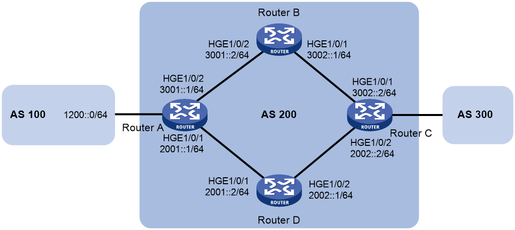
Procedure
|
|
NOTE: By default, interfaces on the device are disabled (in ADM or Administratively Down state). To have an interface operate, you must use the undo shutdown command to enable that interface. |
1. Configure IPv6 addresses for interfaces. (Details not shown.)
2. Configure OSPFv3 so that Router A and Router C can reach each other. (Details not shown.)
3. Configure IPv6 BGP on Router A:
# Establish two IBGP connections to Router C.
<RouterA> system-view
[RouterA] bgp 200
[RouterA-bgp-default] router-id 1.1.1.1
[RouterA-bgp-default] peer 2002::2 as-number 200
[RouterA-bgp-default] peer 3002::2 as-number 200
[RouterA-bgp-default] address-family ipv6
[RouterA-bgp-default-ipv6] peer 2002::2 enable
[RouterA-bgp-default-ipv6] peer 3002::2 enable
[RouterA-bgp-default-ipv6] quit
# Create IPv6 basic ACL 2000 to permit 1200::0/64 to pass.
[RouterA] acl ipv6 basic 2000
[RouterA-acl-ipv6-basic-2000] rule permit source 1200:: 64
[RouterA-acl-ipv6-basic-2000] quit
# Create two routing policies to set the MED for route 1200::0/64. The policy apply_med_50 sets the MED to 50, and the policy apply_med_100 sets the MED to 100.
[RouterA] route-policy apply_med_50 permit node 10
[RouterA-route-policy-apply_med_50-10] if-match ipv6 address acl 2000
[RouterA-route-policy-apply_med_50-10] apply cost 50
[RouterA-route-policy-apply_med_50-10] quit
[RouterA] route-policy apply_med_100 permit node 10
[RouterA-route-policy-apply_med_100-10] if-match ipv6 address acl 2000
[RouterA-route-policy-apply_med_100-10] apply cost 100
[RouterA-route-policy-apply_med_100-10] quit
# Apply routing policy apply_med_50 to routes outgoing to peer 3002::2, and apply routing policy apply_med_100 to routes outgoing to peer 2002::2.
[RouterA] bgp 200
[RouterA-bgp-default] address-family ipv6 unicast
[RouterA-bgp-default-ipv6] peer 3002::2 route-policy apply_med_50 export
[RouterA-bgp-default-ipv6] peer 2002::2 route-policy apply_med_100 export
[RouterA-bgp-default-ipv6] quit
# Enable BFD for peer 3002::2.
[RouterA-bgp-default] peer 3002::2 bfd
[RouterA-bgp-default] quit
4. Configure IPv6 BGP on Router C:
# Establish two IBGP connections to Router A.
<RouterC> system-view
[RouterC] bgp 200
[RouterC-bgp-default] router-id 3.3.3.3
[RouterC-bgp-default] peer 3001::1 as-number 200
[RouterC-bgp-default] peer 2001::1 as-number 200
[RouterC-bgp-default] address-family ipv6
[RouterC-bgp-default-ipv6] peer 3001::1 enable
[RouterC-bgp-default-ipv6] peer 2001::1 enable
[RouterC-bgp-default-ipv6] quit
# Enable BFD for peer 3001::1.
[RouterC-bgp-default] peer 3001::1 bfd
[RouterC-bgp-default] quit
[RouterC] quit
Verifying the configuration
# Display detailed BFD session information on Router C.
<RouterC> display bfd session verbose
Total Session Num: 1 Up Session Num: 1 Init Mode: Active
IPv6 Session Working in control packet mode:
Local Discr: 513 Remote Discr: 513
Source IP: 3002::2
Destination IP: 3001::1
Session State: Up Interface: N/A
Min Tx Inter: 500ms Act Tx Inter: 500ms
Min Rx Inter: 500ms Detect Inter: 2500ms
Rx Count: 13 Tx Count: 14
Connect Type: Indirect Running Up for: 00:00:05
Hold Time: 2243ms Auth mode: None
Detect Mode: Async Slot: 0
Protocol: BGP4+
Version:1
Diag Info: No Diagnostic
The output shows that a BFD session has been established between Router A and Router C.
# Display BGP peer information on Router C.
<RouterC> display bgp peer ipv6
BGP local router ID: 3.3.3.3
Local AS number: 200
Total number of peers: 2 Peers in established state: 2
* - Dynamically created peer
Peer AS MsgRcvd MsgSent OutQ PrefRcv Up/Down State
2001::1 200 8 8 0 0 00:04:45 Established
3001::1 200 5 4 0 0 00:01:53 Established
The output shows that Router C has established two BGP connections with Router A, and both connections are in Established state.
# Display route 1200::0/64 on Router C.
<RouterC> display ipv6 routing-table 1200::0 64 verbose
Summary count : 1
Destination: 1200::/64
Protocol: BGP4+ Process ID: 0
SubProtID: 0x1 Age: 00h01m07s
Cost: 50 Preference: 255
IpPre: N/A QosLocalID: N/A
Tag: 0 State: Active Adv
OrigTblID: 0x1 OrigVrf: default-vrf
TableID: 0xa OrigAs: 0
NibID: 0x25000001 LastAs: 0
AttrID: 0x1 Neighbor: 3001::1
Flags: 0x10060 OrigNextHop: 3001::1
Label: NULL RealNextHop: FE80::20C:29FF:FE4A:3873
BkLabel: NULL BkNextHop: N/A
SRLabel: NULL BKSRLabel: NULL
SIDIndex: NULL InLabel: NULL
Tunnel ID: Invalid Interface: HundredGigE1/0/1
BkTunnel ID: Invalid BkInterface: N/A
FtnIndex: 0x0 TrafficIndex: N/A
Connector: N/A PathID: 0x0
SRTunnelID: Invalid
SID Type: N/A Exp: N/A
VpnPeerId: N/A Dscp: N/A
The output shows that Router C communicates with network 1200::0/64 through the path Router C<—>Router B<—>Router A.
# Break down the path Router C<—>Router B<—>Router A and then display route 1200::0/64 on Router C.
<RouterC> display ipv6 routing-table 1200::0 64 verbose
Summary count : 1
Destination: 1200::/64
Protocol: BGP4+ Process ID: 0
SubProtID: 0x1 Age: 00h00m57s
Cost: 100 Preference: 255
IpPre: N/A QosLocalID: N/A
Tag: 0 State: Active Adv
OrigTblID: 0x1 OrigVrf: default-vrf
TableID: 0xa OrigAs: 0
NibID: 0x25000000 LastAs: 0
AttrID: 0x0 Neighbor: 2001::1
Flags: 0x10060 OrigNextHop: 2001::1
Label: NULL RealNextHop: FE80::20C:29FF:FE40:715
BkLabel: NULL BkNextHop: N/A
SRLabel: NULL BKSRLabel: NULL
SIDIndex: NULL InLabel: NULL
Tunnel ID: Invalid Interface: HundredGigE1/0/2
BkTunnel ID: Invalid BkInterface: N/A
FtnIndex: 0x0 TrafficIndex: N/A
Connector: N/A PathID: 0x0
SRTunnelID: Invalid
SID Type: N/A Exp: N/A
VpnPeerId: N/A Dscp: N/A
The output shows that Router C communicates with network 1200::0/64 through the path Router C<—>Router D<—>Router A.
Example: Configuring IPv6 BGP FRR
Network configuration
As shown in Figure 11, configure BGP FRR so that when Link B fails, BGP uses Link A to forward traffic.
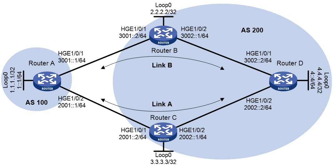
Procedure
|
|
NOTE: By default, interfaces on the device are disabled (in ADM or Administratively Down state). To have an interface operate, you must use the undo shutdown command to enable that interface. |
1. Configure IPv6 addresses for interfaces. (Details not shown.)
2. Configure OSPFv3 in AS 200 to ensure connectivity among Router B, Router C, and Router D. (Details not shown.)
3. Configure BGP connections:
# Configure Router A to establish EBGP sessions to Router B and Router C, and advertise network 1::/64.
<RouterA> system-view
[RouterA] bgp 100
[RouterA] router-id 1.1.1.1
[RouterA-bgp-default] peer 3001::2 as-number 200
[RouterA-bgp-default] peer 2001::2 as-number 200
[RouterA-bgp-default] address-family ipv6 unicast
[RouterA-bgp-default-ipv6] peer 3001::2 enable
[RouterA-bgp-default-ipv6] peer 2001::2 enable
[RouterA-bgp-default-ipv6] network 1:: 64
[RouterA-bgp-default-ipv6] quit
[RouterA-bgp-default] quit
# Configure Router B to establish an EBGP session to Router A, and an IBGP session to Router D.
<RouterB> system-view
[RouterB] bgp 200
[RouterB] router-id 2.2.2.2
[RouterB-bgp-default] peer 3001::1 as-number 100
[RouterB-bgp-default] peer 3002::2 as-number 200
[RouterB-bgp-default] address-family ipv6 unicast
[RouterB-bgp-default-ipv6] peer 3001::1 enable
[RouterB-bgp-default-ipv6] peer 3002::2 enable
[RouterB-bgp-default-ipv6] peer 3002::2 next-hop-local
[RouterB-bgp-default-ipv6] quit
[RouterB-bgp-default] quit
# Configure Router C to establish an EBGP session to Router A, and an IBGP session to Router D.
<RouterC> system-view
[RouterC] bgp 200
[RouterC] router-id 3.3.3.3
[RouterC-bgp-default] peer 2001::1 as-number 100
[RouterC-bgp-default] peer 2002::2 as-number 200
[RouterC-bgp-default] address-family ipv6 unicast
[RouterC-bgp-default-ipv6] peer 2001::1 enable
[RouterC-bgp-default-ipv6] peer 2002::2 enable
[RouterC-bgp-default-ipv6] peer 2002::2 next-hop-local
[RouterC-bgp-default-ipv6] quit
[RouterC-bgp-default] quit
# Configure Router D to establish IBGP sessions to Router B and Router C, and advertise network 4::/64.
<RouterD> system-view
[RouterD] bgp 200
[RouterD-bgp-default] peer 3002::1 as-number 200
[RouterD-bgp-default] peer 2002::1 as-number 200
[RouterD-bgp-default] address-family ipv6 unicast
[RouterD-bgp-default-ipv6] peer 3002::1 enable
[RouterD-bgp-default-ipv6] peer 2002::1 enable
[RouterD-bgp-default-ipv6] network 4:: 64
[RouterD-bgp-default-ipv6] quit
[RouterD-bgp-default] quit
4. Configure preferred values so Link B is used to forward traffic between Router A and Router D:
# Configure Router A to set the preferred value to 100 for routes received from Router B.
[RouterA-bgp-default-ipv6] peer 3001::2 preferred-value 100
[RouterA-bgp-default-ipv6] quit
[RouterA-bgp-default] quit
# Configure Router D to set the preferred value to 100 for routes received from Router B.
[RouterD-bgp-default-ipv6] peer 3002::1 preferred-value 100
[RouterD-bgp-default-ipv6] quit
[RouterD-bgp-default] quit
5. Configure BGP FRR:
# On Router A, create routing policy frr to set a backup next hop 2001::2 (Router C) for the route destined for 4::/64.
<RouterA> system-view
[RouterA] ipv6 prefix-list abc index 10 permit 4:: 64
[RouterA] route-policy frr permit node 10
[RouterA-route-policy] if-match ipv6 address prefix-list abc
[RouterA-route-policy] apply ipv6 fast-reroute backup-nexthop 2001::2
[RouterA-route-policy] quit
# Apply the routing policy to BGP FRR for BGP IPv6 unicast address family.
[RouterA] bgp 100
[RouterA-bgp-default] address-family ipv6 unicast
[RouterA-bgp-default-ipv6] fast-reroute route-policy frr
[RouterA-bgp-default-ipv6] quit
[RouterA-bgp-default] quit
# On Router D, create routing policy frr to set a backup next hop 2002::1 (Router C) for the route destined for 1::/64.
<RouterD> system-view
[RouterD] ipv6 prefix-list abc index 10 permit 1:: 64
[RouterD] route-policy frr permit node 10
[RouterD-route-policy] if-match ipv6 address prefix-list abc
[RouterD-route-policy] apply ipv6 fast-reroute backup-nexthop 2002::1
[RouterD-route-policy] quit
# Apply the routing policy to BGP FRR for BGP IPv6 unicast address family.
[RouterD] bgp 200
[RouterD-bgp-default] address-family ipv6 unicast
[RouterD-bgp-default-ipv6] fast-reroute route-policy frr
[RouterD-bgp-default-ipv6] quit
[RouterD-bgp-default] quit
Verifying the configuration
# Display detailed information about the route to 4::/64 on Router A. The output shows the backup next hop for the route.
[RouterA] display ipv6 routing-table 4:: 64 verbose
Summary count : 1
Destination: 4::/64
Protocol: BGP4+ Process ID: 0
SubProtID: 0x2 Age: 00h00m58s
Cost: 0 Preference: 255
IpPre: N/A QosLocalID: N/A
Tag: 0 State: Active Adv
OrigTblID: 0x0 OrigVrf: default-vrf
TableID: 0xa OrigAs: 200
NibID: 0x25000003 LastAs: 200
AttrID: 0x3 Neighbor: 3001::2
Flags: 0x10060 OrigNextHop: 3001::2
Label: NULL RealNextHop: 3001::2
BkLabel: NULL BkNextHop: 2001::2
SRLabel: NULL BKSRLabel: NULL
SIDIndex: NULL InLabel: NULL
Tunnel ID: Invalid Interface: HundredGigE1/0/1
BkTunnel ID: Invalid BkInterface: HundredGigE1/0/2
FtnIndex: 0x0 TrafficIndex: N/A
Connector: N/A PathID: 0x0
SRTunnelID: Invalid
SID Type: N/A Exp: N/A
VpnPeerId: N/A Dscp: N/A
# Display detailed information about the route to 1::/64 on Router D. The output shows the backup next hop for the route.
[RouterD] display ipv6 routing-table 1:: 64 verbose
Summary count : 1
Destination: 1::/64
Protocol: BGP4+ Process ID: 0
SubProtID: 0x1 Age: 00h03m24s
Cost: 0 Preference: 255
IpPre: N/A QosLocalID: N/A
Tag: 0 State: Active Adv
OrigTblID: 0x0 OrigVrf: default-vrf
TableID: 0xa OrigAs: 100
NibID: 0x25000003 LastAs: 100
AttrID: 0x4 Neighbor: 3002::1
Flags: 0x10060 OrigNextHop: 3002::1
Label: NULL RealNextHop: 3002::1
BkLabel: NULL BkNextHop: 2002::1
SRLabel: NULL BKSRLabel: NULL
SIDIndex: NULL InLabel: NULL
Tunnel ID: Invalid Interface: HundredGigE1/0/1
BkTunnel ID: Invalid BkInterface: HundredGigE1/0/2
FtnIndex: 0x0 TrafficIndex: N/A
Connector: N/A PathID: 0x0
SRTunnelID: Invalid
SID Type: N/A Exp: N/A
VpnPeerId: N/A Dscp: N/A
Configuring extended BGP features
Extended BGP feature configuration tasks at a glance
To configure extended BGP features, perform the following tasks:
¡ (Optional.) Configuring BGP LS route reflection
¡ (Optional.) Specifying an AS number and a router ID for BGP LS messages
¡ (Optional.) Performing manual soft-reset for BGP sessions of LS address family
¡ Configuring the BGP Additional Paths feature for 6PE
¡ (Optional.) Controlling path selection for 6PE
¡ (Optional.) Controlling 6PE route advertisement and reception
¡ (Optional.) Tuning and optimizing 6PE
¡ (Optional.) Configuring 6PE route reflection
¡ (Optional.) Resetting 6PE connections
Configuring BMP
About this task
The BGP monitoring protocol (BMP) enables a BGP router (BMP client) to send session status information of the specified peers to BMP servers for monitoring. The session status information includes peer relationship establishment and termination as well as routing information. The BMP client communicates with the BMP servers through TCP connections.
Procedure
1. Enter system view.
system-view
2. Create a BMP server and enter BMP server view.
bmp server server-number
3. Configure an IP address and port number for the BMP server.
server address ipv4-address port port-number
By default, no IP address and port number are configured for the BMP server.
4. Set the interval at which BGP sends statistics information to the BMP server.
statistics-interval value
By default, BGP does not send statistics information to the BMP server.
5. (Optional.) Specify a VPN instance for the BMP server.
server vpn-instance vpn-instance-name
By default, no VPN instance is specified for a BMP server. A BMP server belongs to the public network.
6. (Optional.) Specify the source interface of TCP connections to the BMP server.
server connect-interface interface-type interface-number
By default, BGP uses the primary IPv4 address of the output interface in the optimal route to the BMP server as the source address of TCP connections to the BMP server.
For a BMP server, this command does not take effect if the VPN instance of the specified interface is different from that specified by the server vpn-instance command.
7. (Optional.) Specify the authentication mode and key for the local device to establish TCP connections to the BMP server.
server password { keychain keychain-name | md5 { cipher | simple } string }
By default, the local device establishes TCP connections to the BMP server without authentication.
8. (Optional.) Enable BGP to send routes to the BMP server globally. Choose the options to configure as needed:
¡ Enable BGP to send routes advertised to all the monitored peers and peer groups to the BMP server.
route-mode adj-rib-out [ pre-policy | post-policy | both ]
By default, BGP does not send routes advertised to a monitored peer or peer group to the BMP server.
¡ Enable BGP to send routes received from all the monitored peers and peer groups to the BMP server.
route-mode adj-rib-in [ pre-policy | post-policy | both ]
By default, BGP does not send routes received from a monitored peer or peer group to the BMP server.
¡ Configure BGP to send the optimal routes in the routing table to the BMP server.
route-mode loc-rib
By default, BGP does not send the optimal routes in the routing table to the BMP server.
With this feature configured, BGP sends all routes to the BMP server first. If routes update later, BGP sends only the optimal routes to the server.
9. Return to system view.
quit
10. Enter BGP instance view or BGP-VPN instance view.
¡ Enter BGP instance view.
bgp as-number [ instance instance-name ]
¡ Enter BGP-VPN instance view.
bgp as-number [ instance instance-name ]
ip vpn-instance vpn-instance-name
11. Specify a peer or peer group to be monitored.
peer { group-name | ipv4-address [ mask-length ] | ipv6-address [ prefix-length ] } bmp server server-number-list
By default, no peer or peer group is specified.
If you execute this command multiple times for a peer or peer group, the most recent configuration takes effect.
12. (Optional.) Enable BGP to send routes exchanged with the specified monitored peer or peer group to the BMP server.
peer { group-name | ipv4-address [ mask-length ] | ipv6-address [ prefix-length ] } route-mode { adj-rib-in { pre-policy | post-policy | both } | adj-rib-out { pre-policy | post-policy | both } } *
By default, BGP determines whether to send routes exchanged with a peer or peer group to the BMP server based on the following configurations:
¡ Configuration of the route-mode adj-rib-in command in BMP server view.
¡ Configuration of the route-mode adj-rib-out command in BMP server view.
Verifying and maintaining BMP
To display BMP server information, execute the following command in any view:
display bgp [ instance instance-name ] bmp server server-number
To clear BMP server statistics, execute the following command in user view:
reset bgp [ instance instance-name ] bmp server server-number statistics
Configuring BGP LS
About BGP LS
The BGP Link State (LS) feature implements inter-domain and inter-AS advertisement of link state database (LSDB) and TE database (TEDB) information.
The device sends the collected link state information to the controller, which implements end-to-end traffic management and scheduling and meets the requirements of intended applications.
Configuring basic BGP LS
1. Enter system view.
system-view
2. Enter BGP instance view.
bgp as-number [ instance instance-name ]
3. Specify an AS number for an LS peer or peer group.
peer { { ipv4-address [ mask-length ] | ipv6-address [ prefix-length ] } | group-name } as-number as-number
By default, no AS number is specified.
4. Create the BGP LS address family and enter its view.
address-family link-state
5. Enable the device to exchange LS information with the peer or peer group.
peer { group-name | ipv4-address [ mask-length ] | ipv6-address [ prefix-length ] } enable
By default, the device cannot exchange LS information with the peer or peer group.
Configuring BGP LS route reflection
About this task
Perform this task to configure a BGP route reflector and its clients. The route reflector and its clients automatically form a cluster identified by the router ID of the route reflector. The route reflector forwards route updates among its clients.
Procedure
1. Enter system view.
system-view
2. Enter BGP instance view.
bgp as-number [ instance instance-name ]
3. Enter BGP LS address family view.
address-family link-state
4. Configure BGP LS route reflection.
¡ Configure the device as a route reflector and specify a peer or peer group as its client.
peer { group-name | ipv4-address [ mask-length ] | ipv6-address [ prefix-length ] } reflect-client
By default, no route reflector or client is configured.
¡ (Optional.) Enable route reflection between clients.
reflect between-clients
By default, route reflection between clients is enabled.
This command can reduce the number of IBGP connections in an AS.
¡ (Optional.) Configure the cluster ID of the route reflector.
reflector cluster-id { cluster-id | ipv4-address }
By default, a route reflector uses its own router ID as the cluster ID.
Specifying an AS number and a router ID for BGP LS messages
1. Enter system view.
system-view
2. Enter BGP instance view.
bgp as-number [ instance instance-name ]
3. Enter BGP LS address family view.
address-family link-state
4. Specify an AS number and a router ID for BGP LS messages.
domain-distinguisher as-number:router-id
By default, the AS number and router ID of the current BGP process are used.
Configure this command to ensure that LS messages sent by devices in the same AS have the same AS number and router ID.
Performing manual soft-reset for BGP sessions of LS address family
1. Enter system view.
system-view
2. Enter BGP instance view.
bgp as-number [ instance instance-name ]
3. Enable BGP route refresh.
¡ Enable BGP route refresh for a peer or peer group.
peer { group-name | ipv4-address [ mask-length ] | ipv6-address [ prefix-length ] } capability-advertise route-refresh
¡ Enable the BGP route refresh, multi-protocol extension, and 4-byte AS number features for a peer or peer group.
undo peer { group-name | ipv4-address [ mask-length ] | ipv6-address [ prefix-length ] } capability-advertise conventional
By default, the BGP route refresh, multi-protocol extension, and 4-byte AS number features are enabled.
4. Perform manual soft-reset for BGP sessions of LS address family:
a. Return to system view.
quit
b. Return to user view.
quit
c. Perform manual soft-reset for BGP sessions of LS address family.
refresh bgp [ instance instance-name ] { ipv4-address [ mask-length ] | ipv6-address [ prefix-length ] | all | external | group group-name | internal } { export | import } link-state
Verifying and maintaining BGP LS
Verifying BGP LS configuration and running status
Perform display tasks in any view.
· Display BGP LS peer group information.
display bgp [ instance instance-name ] group link-state [ group-name group-name ]
· Display BGP LS peer or peer group information.
display bgp [ instance instance-name ] peer link-state [ ipv4-address mask-length | ipv6-address prefix-length | { ipv4-address | ipv6-address | group-name group-name } log-info | [ ipv4-address | ipv6-address ] verbose ]
· Display BGP LS address family information.
display bgp [ instance instance-name ] link-state [ ls-prefix | peer { ipv4-address | ipv6-address } { advertised | received } [ statistics ] | statistics ]
· Display BGP update group information for the LS address family.
display bgp [ instance instance-name ] update-group link-state [ ipv4-address | ipv6-address ]
Resetting BGP session in the LS address family
To reset BGP sessions in the LS address family, execute the following command in user view:
reset bgp [ instance instance-name ] { as-number | ipv4-address [ mask-length ] | ipv6-address [ prefix-length ] | all | external | group group-name | internal } link-state
Configuring 6PE
About 6PE
IPv6 provider edge (6PE) is a transition technology that uses MPLS to connect sparsely populated IPv6 networks through an existing IPv4 backbone network. It is an efficient solution for ISP IPv4/MPLS networks to provide IPv6 traffic switching capability.
Figure 12 Network diagram for 6PE
6PE mainly performs the following operations:
· 6PE assigns a label to IPv6 routing information received from a CE router, and sends the labeled IPv6 routing information to the peer 6PE device through an MP-BGP session. The peer 6PE device then forwards the IPv6 routing information to the attached customer site.
· 6PE provides tunnels over the IPv4 backbone so the IPv4 backbone can forward packets for IPv6 networks. The tunnels can be GRE tunnels, MPLS LSPs, or MPLS TE tunnels.
· Upon receiving an IPv6 packet, 6PE adds an inner tag (corresponding to the IPv6 packet) and then an outer tag (corresponding to the public network tunnel) to the IPv6 packet. Devices in the IPv4 backbone network forwards the packet based on the outer tag. When the peer 6PE device receives the packet, it removes the outer and inner tags and forwards the original IPv6 packet to the attached customer site.
To implement exchange of IPv6 routing information, you can configure IPv6 static routing, an IPv6 IGP protocol, or IPv6 BGP between CE and 6PE devices.
For more information about MPLS, MPLS TE, CE, and P, see MPLS Configuration Guide. For more information about GRE, see Layer 3—IP Services Configuration Guide.
Prerequisites
Before you configure 6PE, perform the following tasks:
· Establish tunnels in the IPv4 backbone network (see Layer 3—IP Services Configuration Guide).
· Configure basic MPLS on 6PE devices (see MPLS Configuration Guide).
· Configure BGP on 6PE devices so that they can advertise tagged IPv6 routing information through BGP sessions. The following tasks describe only BGP configurations on 6PE devices.
Configuring basic 6PE
1. Enter system view.
system-view
2. Enter BGP instance view.
bgp as-number [ instance instance-name ]
3. Specify a 6PE peer or peer group and its AS number.
peer { group-name | ipv4-address [ mask-length ] } as-number as-number
By default, no 6PE peer is specified.
4. Enter BGP IPv6 unicast address family view.
address-family ipv6 [ unicast ]
5. Enable BGP to exchange IPv6 unicast routing information with the 6PE peer or peer group.
peer { group-name | ipv4-address [ mask-length ] } enable
By default, BGP cannot exchange IPv6 unicast routing information with a 6PE peer or peer group.
6. Enable BGP to exchange labeled IPv6 routes with the 6PE peer or peer group.
peer { group-name | ipv4-address [ mask-length ] } label-route-capability
By default, BGP cannot exchange labeled IPv6 routes with a 6PE peer or peer group.
Configuring the BGP Additional Paths feature for 6PE
1. Enter system view.
system-view
2. Enter BGP instance view.
bgp as-number [ instance instance-name ]
3. Enter BGP IPv6 unicast address family view.
address-family ipv6 [ unicast ]
4. Configure the BGP Additional Paths capabilities for a 6PE peer or peer group.
peer { group-name | ipv4-address [ mask-length ] } additional-paths { receive | send } *
By default, no BGP Additional Paths capabilities are configured for a 6PE peer or peer group.
5. Set the maximum number of Add-Path optimal routes that can be advertised to a 6PE peer or peer group.
peer { group-name | ipv4-address [ mask-length ] } advertise additional-paths best number
By default, BGP does not advertise Add-Path optimal routes to a 6PE peer or peer group.
Controlling path selection for 6PE
1. Enter system view.
system-view
2. Enter BGP instance view.
bgp as-number [ instance instance-name ]
3. Enter BGP IPv6 unicast address family view.
address-family ipv6 [ unicast ]
4. Advertise COMMUNITY attribute to a 6PE peer or peer group.
peer { group-name | ipv4-address [ mask-length ] } advertise-community
By default, the COMMUNITY attribute is not advertised.
5. Advertise extended community attribute to a 6PE peer or peer group.
peer { group-name | ipv4-address [ mask-length ] } advertise-ext-community
By default, the extended community attribute is not advertised.
6. Remove private AS numbers in BGP updates sent to a 6PE peer or peer group.
peer { group-name | ipv4-address [ mask-length ] } public-as-only
By default, BGP updates sent to a 6PE peer or peer group can carry both public and private AS numbers.
7. Specify a preferred value for routes received from a 6PE peer or peer group.
peer { group-name | ipv4-address [ mask-length ] } preferred-value value
By default, the preferred value for routes received from a 6PE peer or peer group is 0.
8. Enable BGP to add the link bandwidth attribute to routes received from a 6PE peer or peer group.
peer { group-name | ipv6-address [ prefix-length ] } bandwidth
By default, BGP does not add the link bandwidth attribute to routes received from a 6PE peer or peer group.
9. Configure BGP to advertise the AIGP attribute to the specified peer or peer group.
peer { group-name | ipv4-address [ mask-length ] } aigp
By default, BGP does not advertise the AIGP attribute to a peer or peer group.
10. Replace the MED value with AIGP value in routes advertised to the specified peer or peer group.
peer { group-name | ipv4-address [ mask-length ] } aigp send med
By default, BGP does not replace the MED value with AIGP value in routes advertised to a peer or peer group.
Controlling 6PE route advertisement and reception
1. Enter system view.
system-view
2. Enter BGP instance view.
bgp as-number [ instance instance-name ]
3. Enter BGP IPv6 unicast address family view.
address-family ipv6 [ unicast ]
4. Advertise a default route to a 6PE peer or peer group.
peer { group-name | ipv4-address [ mask-length ] } default-route-advertise [ route-policy route-policy-name ]
By default, no default route is advertised to a 6PE peer or peer group.
5. Configure route filtering policies.
¡ Specify an AS path list to filter routes advertised to or received from a 6PE peer or peer group.
peer { group-name | ipv4-address [ mask-length ] } as-path-acl { as-path-acl-number | as-path-acl-name } { export | import }
By default, no AS path list is specified.
¡ Specify an IPv6 ACL to filter routes advertised to or received from a 6PE peer or peer group.
peer { group-name | ipv4-address [ mask-length ] } filter-policy { ipv6-acl-number | name ipv6-acl-name } { export | import }
By default, no IPv6 ACL is specified.
¡ Specify an IPv6 prefix list to filter routes advertised to or received from a 6PE peer or peer group.
peer { group-name | ipv4-address [ mask-length ] } prefix-list ipv6-prefix-list-name { export | import }
By default, no IPv6 prefix list is specified.
¡ Specify a routing policy to filter routes advertised to or received from a 6PE peer or peer group.
peer { group-name | ipv4-address [ mask-length ] } route-policy route-policy-name { export | import }
By default, no routing policy is specified.
6. Save all routes from a 6PE peer or peer group.
peer { group-name | ipv4-address [ mask-length ] } keep-all-routes
By default, routes from a 6PE peer or peer group are not saved.
7. Set the maximum number of routes that BGP can receive from a 6PE peer or peer group.
peer { group-name | ipv4-address [ mask-length ] } route-limit prefix-number [ { alert-only | discard | reconnect reconnect-time } | percentage-value ] *
By default, the number of routes that BGP can receive from a 6PE peer or peer group is not limited.
8. Configure the SoO attribute for a peer or peer group.
peer { group-name | ipv4-address [ mask-length ] } soo site-of-origin
By default, no SoO attribute is configured for a peer or peer group.
Tuning and optimizing 6PE
1. Enter system view.
system-view
2. Enter BGP instance view.
bgp as-number [ instance instance-name ]
3. Enter BGP IPv6 unicast address family view.
address-family ipv6 [ unicast ]
4. Allow the local AS number to appear in routes from a 6PE peer or peer group and specify the repeat times.
peer { group-name | ipv4-address [ mask-length ] } allow-as-loop [ number ]
By default, the local AS number is not allowed to appear in routes from a 6PE peer or peer group.
Configuring 6PE route reflection
1. Enter system view.
system-view
2. Enter BGP instance view.
bgp as-number [ instance instance-name ]
3. Enter BGP IPv6 unicast address family view.
address-family ipv6 [ unicast ]
4. Configure the device as a route reflector and a 6PE peer or peer group as a client.
peer { group-name | ipv4-address [ mask-length ] } reflect-client
By default, no route reflector or client is configured.
Resetting 6PE connections
To reset 6PE connections, execute one of the following commands in user view:
· Soft-reset a BGP 6PE connection.
refresh bgp [ instance instance-name ] ipv4-address [ mask-length ] { export | import } ipv6 [ unicast ]
· Reset a BGP 6PE connection.
reset bgp [ instance instance-name ] ipv4-address [ mask-length ] ipv6 [ unicast ]
|
|
CAUTION: A reset operation tears down BGP sessions for a short period of time. |
Extended IPv4 BGP feature configuration examples
Example: Configuring BGP LS
Network configuration
As shown in Figure 13, all routers run BGP. Run IBGP between Router A and Router B, between Router B and Router C, and between Router B and Router D.
Configure Router B as a route reflector with client Router A to allow Router A to learn LS information advertised by Router C and Router D.
Procedure
|
|
NOTE: By default, interfaces on the device are disabled (in ADM or Administratively Down state). To have an interface operate, you must use the undo shutdown command to enable that interface. |
1. Configure IP addresses for interfaces and configure OSPF on Router C and Router D. (Details not shown.)
2. Configure BGP connections:
# Configure Router A.
<RouterA> system-view
[RouterA] bgp 100
[RouterA-bgp-default] peer 192.1.1.2 as-number 100
[RouterA-bgp-default] address-family link-state
[RouterA-bgp-default-ls] peer 192.1.1.2 enable
[RouterA-bgp-default-ls] quit
[RouterA-bgp-default] quit
# Configure Router B.
<RouterB> system-view
[RouterB] bgp 100
[RouterB-bgp-default] peer 192.1.1.1 as-number 100
[RouterB-bgp-default] peer 193.1.1.1 as-number 100
[RouterB-bgp-default] peer 194.1.1.1 as-number 100
[RouterB-bgp-default] address-family link-state
[RouterB-bgp-default-ls] peer 192.1.1.1 enable
[RouterB-bgp-default-ls] peer 193.1.1.1 enable
[RouterB-bgp-default-ls] peer 194.1.1.1 enable
[RouterB-bgp-default-ls] quit
[RouterB-bgp-default] quit
# Configure Router C.
<RouterC> system-view
[RouterC] bgp 100
[RouterC-bgp-default] peer 193.1.1.2 as-number 100
[RouterC-bgp-default] address-family link-state
[RouterC-bgp-default-ls] peer 193.1.1.2 enable
[RouterC-bgp-default-ls] quit
[RouterC-bgp-default] quit
[RouterC] ospf
[RouterC-ospf-1] distribute bgp-ls
[RouterC-ospf-1] area 0
[RouterC-ospf-1-area-0.0.0.0] network 0.0.0.0 0.0.0.0
[RouterC-ospf-1-area-0.0.0.0] quit
[RouterC-ospf-1] quit
# Configure Router D.
<RouterD> system-view
[RouterD] bgp 100
[RouterD-bgp-default] peer 194.1.1.2 as-number 100
[RouterD-bgp-default] address-family link-state
[RouterD-bgp-default-ls] peer 194.1.1.2 enable
[RouterD-bgp-default-ls] quit
[RouterD-bgp-default] quit
[RouterD] ospf
[RouterD-ospf-1] distribute bgp-ls
[RouterD-ospf-1] area 0
[RouterD-ospf-1-area-0.0.0.0] network 0.0.0.0 0.0.0.0
[RouterD-ospf-1-area-0.0.0.0] quit
[RouterD-ospf-1] quit
3. Configure Router B as the route reflector.
[RouterB] bgp 100
[RouterB-bgp-default] address-family link-state
[RouterB-bgp-default-ls] peer 192.1.1.1 reflect-client
[RouterB-bgp-default-ls] quit
[RouterB-bgp-default] quit
Verifying the configuration
# Verify that Router A has learned LS information advertised by Router C and Router D.
[RouterA] display bgp link-state
Total number of routes: 4
BGP local router ID is 192.1.1.1
Status codes: * - valid, > - best, d - dampened, h - history,
s - suppressed, S - stale, i - internal, e - external
a – additional-path
Origin: i - IGP, e - EGP, ? - incomplete
Prefix codes: E link, V node, T IP reachable route, u/U unknown,
I Identifier, N local node, R remote node, L link, P prefix,
L1/L2 ISIS level-1/level-2, O OSPF, D direct, S static,
a area-ID, , l link-ID, t topology-ID, s ISO-ID,
c confed-ID/ASN, b bgp-identifier, r router-ID,
i if-address, n peer-address, o OSPF Route-type, p IP-prefix
d designated router address
i Network : [V][O][I0x0][N[c100][b193.1.1.1][a0.0.0.0][r193.1.1.1]]/376
NextHop : 193.1.1.1 LocPrf : 100
PrefVal : 0 OutLabel : NULL
MED :
Path/Ogn: i
i Network : [V][O][I0x0][N[c100][b194.1.1.1][a0.0.0.0][r194.1.1.1]]/376
NextHop : 194.1.1.1 LocPrf : 100
PrefVal : 0 OutLabel : NULL
MED :
Path/Ogn: i
i Network : [T][O][I0x0][N[c100][b193.1.1.1][a0.0.0.0][r193.1.1.1]][P[o0x1][p193.1.1.0/24]]/480
NextHop : 193.1.1.1 LocPrf : 100
PrefVal : 0 OutLabel : NULL
MED :
Path/Ogn: i
i Network : [T][O][I0x0][N[c100][b194.1.1.1][a0.0.0.0][r194.1.1.1]][P[o0x1][p194.1.1.0/24]]/480
NextHop : 194.1.1.1 LocPrf : 100
PrefVal : 0 OutLabel : NULL
MED :
Path/Ogn: i
Extended IPv6 BGP feature configuration examples
Example: Configuring 6PE
Network configuration
Use 6PE to connect two isolated IPv6 networks over an IPv4/MPLS network.
· The ISP uses OSPF as the IGP.
· PE 1 and PE 2 are edge devices of the ISP, and establish an IPv4 IBGP connection between them.
· CE 1 and CE 2 are edge devices of the IPv6 networks, and they connect the IPv6 networks to the ISP.
· A CE and a PE exchange IPv6 packets through IPv6 static routing.
Figure 14 Network diagram
Procedure
|
|
NOTE: By default, interfaces on the device are disabled (in ADM or Administratively Down state). To have an interface operate, you must use the undo shutdown command to enable that interface. |
1. Configure IPv6 addresses and IPv4 addresses for interfaces. (Details not shown.)
2. Configure PE 1:
# Enable LDP globally, and configure the LSP generation policy.
<PE1> system-view
[PE1] mpls lsr-id 2.2.2.2
[PE1] mpls ldp
[PE1-ldp] lsp-trigger all
[PE1-ldp] quit
# Enable MPLS and LDP on HundredGigE 1/0/2.
[PE1] interface hundredgige 1/0/2
[PE1-HundredGigE1/0/2] mpls enable
[PE1-HundredGigE1/0/2] mpls ldp enable
[PE1-HundredGigE1/0/2] quit
# Configure IBGP, enable the peer's 6PE capabilities, and redistribute IPv6 direct and static routes.
[PE1] bgp 65100
[PE1-bgp-default] router-id 2.2.2.2
[PE1-bgp-default] peer 3.3.3.3 as-number 65100
[PE1-bgp-default] peer 3.3.3.3 connect-interface loopback 0
[PE1-bgp-default] address-family ipv6
[PE1-bgp-default-ipv6] import-route direct
[PE1-bgp-default-ipv6] import-route static
[PE1-bgp-default-ipv6] peer 3.3.3.3 enable
[PE1-bgp-default-ipv6] peer 3.3.3.3 label-route-capability
[PE1-bgp-default-ipv6] quit
[PE1-bgp-default] quit
# Configure the static route to CE 1.
[PE1] ipv6 route-static 1::1 128 10::1
# Configure OSPF for the ISP.
[PE1] ospf
[PE1-ospf-1] area 0
[PE1-ospf-1-area-0.0.0.0] network 2.2.2.2 0.0.0.0
[PE1-ospf-1-area-0.0.0.0] network 1.1.0.0 0.0.255.255
[PE1-ospf-1-area-0.0.0.0] quit
[PE1-ospf-1] quit
3. Configure PE 2:
# Enable LDP globally, and configure the LSP generation policy.
<PE2> system-view
[PE2] mpls lsr-id 3.3.3.3
[PE2] mpls ldp
[PE2-mpls-ldp] lsp-trigger all
[PE2-mpls-ldp] quit
# Enable MPLS and LDP on HundredGigE 1/0/2.
[PE2] interface hundredgige 1/0/2
[PE2-HundredGigE1/0/2] mpls enable
[PE2-HundredGigE1/0/2] mpls ldp enable
[PE2-HundredGigE1/0/2] quit
# Configure IBGP, enable the peer's 6PE capabilities, and redistribute IPv6 direct and static routes.
[PE2] bgp 65100
[PE2-bgp-default] router-id 3.3.3.3
[PE2-bgp-default] peer 2.2.2.2 as-number 65100
[PE2-bgp-default] peer 2.2.2.2 connect-interface loopback 0
[PE2-bgp-default] address-family ipv6
[PE2-bgp-default-ipv6] import-route direct
[PE2-bgp-default-ipv6] import-route static
[PE2-bgp-default-ipv6] peer 2.2.2.2 enable
[PE2-bgp-default-ipv6] peer 2.2.2.2 label-route-capability
[PE2-bgp-default-ipv6] quit
[PE2-bgp-default] quit
# Configure the static route to CE 2.
[PE2] ipv6 route-static 4::4 128 20::1
# Configure OSPF for the ISP.
[PE2] ospf
[PE2-ospf-1] area 0
[PE2-ospf-1-area-0.0.0.0] network 3.3.3.3 0.0.0.0
[PE2-ospf-1-area-0.0.0.0] network 1.1.0.0 0.0.255.255
[PE2-ospf-1-area-0.0.0.0] quit
[PE2-ospf-1] quit
4. Configure a static route, with PE 1 as the default next hop.
<CE1> system-view
[CE1] ipv6 route-static :: 0 10::2
5. Configure a static route on CE 2, with PE 2 as the default next hop.
<CE2> system-view
[CE2] ipv6 route-static :: 0 20::2
Verifying the configuration
# Display the IPv6 BGP routing tables on PE 1 and PE 2. The output shows that each of them has two IPv6 network routes. The following shows the output on PE 1:
[PE1] display bgp routing-table ipv6
Total number of routes: 5
BGP local router ID is 2.2.2.2
Status codes: * - valid, > - best, d - dampened, h - history,
s - suppressed, S - stale, i - internal, e - external
a – additional-path
Origin: i - IGP, e - EGP, ? - incomplete
* > Network : 1::1 PrefixLen : 128
NextHop : 10::1 LocPrf :
PrefVal : 32768 OutLabel : NULL
MED : 0
Path/Ogn: ?
* >i Network : 4::4 PrefixLen : 128
NextHop : ::FFFF:3.3.3.3 LocPrf : 100
PrefVal : 0 OutLabel : 1279
MED : 0
Path/Ogn: ?
* > Network : 10:: PrefixLen : 64
NextHop : :: LocPrf :
PrefVal : 32768 OutLabel : NULL
MED : 0
Path/Ogn: ?
* > Network : 10::2 PrefixLen : 128
NextHop : ::1 LocPrf :
PrefVal : 32768 OutLabel : NULL
MED : 0
Path/Ogn: ?
* >i Network : 20:: PrefixLen : 64
NextHop : ::FFFF:3.3.3.3 LocPrf : 100
PrefVal : 0 OutLabel : 1278
MED : 0
Path/Ogn: ?
# Verify that CE 1 can ping the IPv6 address 4::4 (loopback interface address) of CE 2. (Details not shown.)