- Table of Contents
- Related Documents
-
| Title | Size | Download |
|---|---|---|
| 01-Text | 1.17 MB |
Contents
About the SeerEngine-DC controller
Deployment procedure at a glance
Registering and installing licenses
Registering and installing licenses for SNA Center
Registering and installing licenses for the controller
Installing the activation file on the license server
Backing up and restoring the controller configuration
Scaling out or in the controller
Deploying the primary and backup sites and a third-party site
About the SeerEngine-DC controller
SeerEngine-DC (also called VCFC-DataCenter) is a data center controller that runs on SeerNetwork Architecture (SNA) Center. SNA Center is the core component of a digital network to provide unified network management, control, intelligent analysis, and service orchestration.
Similar to a network operating system, the SeerEngine-DC controller allows users to develop and run SDN applications. It can control various resources on an OpenFlow network and provide interfaces for applications to enable specific network forwarding.
The controller has the following features:
· It supports OpenFlow 1.3 and provides built-in services and a device driver framework.
· It is a distributed platform with high availability and scalability.
· It provides extensible REST APIs, GUI, and H3C IMC management interface.
Preparing for installation
Server requirements
Hardware requirements
|
|
CAUTION: Make sure the server to host the controller meets the hardware requirements. A lower-level hardware configuration might degrade the controller performance or fail to support some services. |
Node to host the controller
Table 1 and Table 2 describe the hardware requirements for the node to host the controller.
Table 1 Hardware requirements for the node to host the controller (recommended configuration)
|
Item |
Requirements |
|
CPU |
x86-64 (Intel 64/AMD 64) 20 cores 2.2 GHz or above |
|
Memory size |
128 GB or above |
|
Drive |
The drives must be set up in RAID 1, 5, or 10 mode. · Drive configuration option 1: ¡ System drive: SSDs, with a size of 2.4 TB or above in RAID setup. ¡ etcd drive: SSDs, with a size of 50 GB or above in RAID setup. (Installation path: /var/lib/etcd.) · Drive configuration option 2: ¡ System drive: 7.2K RPM SATA/SAS HDDs, with a size of 2.4 TB or above in RAID setup. ¡ etcd drive: 7.2K RPM SATA/SAS HDDs, with a size of 50 GB or above in RAID setup. (Installation path: /var/lib/etcd.) ¡ Storage controller: 1GB cache, power fail protected with a supercapacitor installed. |
|
NIC |
vBGP not configured: · Non-bonding mode: 1 × 10 Gbps or above Ethernet port · Bonding mode (recommended mode: mode 2 or mode 4): 2 × 10 Gbps Linux bonding interfaces vBGP configured: · Non-bonding mode: 2 × 10 Gbps or above Ethernet ports · Bonding mode (recommended mode: mode 4): 4 × 10 Gbps Linux bonding interfaces For the controller to support the remote disaster recovery system (RDRS), add an extra 10 Gbps or above Ethernet port. |
Table 2 Hardware requirements for the node to host the controller (standard configuration)
|
Item |
Requirements |
|
CPU |
x86-64 (Intel 64/AMD 64) 16 cores 2.0 GHz or above |
|
Memory size |
128 GB or above |
|
Drive |
The drives must be set up in RAID 1, 5, or 10 mode. · Drive configuration option 1: ¡ System drive: SSDs, with a size of 2.4 TB or above in RAID setup. ¡ etcd drive: SSDs, with a size of 50 GB or above in RAID setup. (Installation path: /var/lib/etcd.) · Drive configuration option 2: ¡ System drive: 7.2K RPM SATA/SAS HDDs, with a size of 2.4 TB or above in RAID setup. ¡ etcd drive: 7.2K RPM SATA/SAS HDDs, with a size of 50 GB or above in RAID setup. (Installation path: /var/lib/etcd.) ¡ Storage controller: 1GB cache, power fail protected with a supercapacitor installed. |
|
NIC |
vBGP not configured: · Non-bonding mode: 1 × 10 Gbps or above Ethernet port · Bonding mode (recommended mode: mode 2 or mode 4): 2 × 10 Gbps Linux bonding interfaces vBGP configured: · Non-bonding mode: 2 × 10 Gbps or above Ethernet ports · Bonding mode (recommended mode: mode 4): 4 × 10 Gbps Linux bonding interfaces |
|
|
IMPORTANT: The server must support the CentOS 7.6 or later operating system. |
RDRS third-party site
You can deploy the RDRS third-party site on the same server as the primary or backup site. However, automatic RDRS switchover will fail when the server fails. As a best practice, deploy the RDRS third-party site on a separate server.
The RDRS third-party site can be deployed on a physical server. Table 3 and Table 4 describe the hardware requirements for a physical server and a VM to host the RDRS third-party site, respectively.
Table 3 Hardware requirements for a physical server to host the RDRS third-party site
|
Item |
Requirements |
|
CPU |
x86-64 (Intel 64/AMD 64) 2 cores 2.0 GHz or above |
|
Memory size |
16 GB or above |
|
Drive |
The drives must be set up in RAID 1, 5, or 10 mode. · Drive configuration option 1: ¡ System drive: SSDs, with a size of 256 GB or above in RAID setup. ¡ etcd drive: SSDs, with a size of 20 GB or above in RAID setup. (Installation path: /var/lib/etcd.) · Drive configuration option 2: ¡ System drive: 7.2K RPM SATA/SAS HDDs, with a size of 256 GB or above in RAID setup. ¡ etcd drive: 7.2K RPM SATA/SAS HDDs, with a size of 20 GB or above in RAID setup. (Installation path: /var/lib/etcd.) ¡ Storage controller: 1GB cache, power fail protected with a supercapacitor installed. |
|
NIC |
1 × 10 Gbps or above Ethernet port |
Software requirements
SNA Center must be deployed on the H3Linux operating system. This operating system is contained in the SNA_CENTER-PACKAGE-version.iso image with the installation packages of SNA Installer, SNA Center, and license server. You can install the operating system from this image file.
Client requirements
You can access SNA Center from a Web browser without installing any client. As a best practice, use a Google Chrome 60 or later Web browser.
Pre-installation checklist
Table 4 Pre-installation checklist
|
Item |
Requirements |
|
|
Server |
Hardware |
· The CPUs, memory, disks, and NICs meet the requirements. · The server supports the CentOS 7.5 or later operating system. |
|
Software |
The system time settings are configured correctly. As a best practice, configure NTP for time synchronization and make sure the devices synchronize to the same clock source. |
|
|
Client |
You can access SNA Center from a Web browser without installing any client. As a best practice, use a Google Chrome 60 or later Web browser. |
|
Deployment procedure at a glance
Use the following procedure to deploy the controller:
1. Prepare for installation.
Prepare three physical servers. Make sure the physical servers meet the hardware and software requirements as described in "Server requirements."
2. Deploy the H3Linux operating system and SNA Installer.
For the deployment procedure, see H3C SNA Center Installation and Component Deployment Guide.
3. Install SNA Center.
For the SNA Center installation procedure, see H3C SNA Center Installation and Component Deployment Guide.
4. Deploy the controller.
Installing SNA Center
The controller must be deployed on SNA Center. To deploy the controller, first install SNA Center. For the SNA Center installation procedure, see H3C SNA Center Installation and Component Deployment Guide.
Deploying the controller
|
|
IMPORTANT: The controller runs on SNA Center. You can deploy, upgrade, and uninstall it only on SNA Center. |
Preparing for deployment
Enabling NICs
If the server uses multiple NICs for connecting to the network. Enable the NICs before deployment.
The procedure is the same for all NICs. The following procedure enables NIC ens34.
To enable a NIC:
1. Access the server that hosts SNA Center.
2. Access the NIC configuration file.
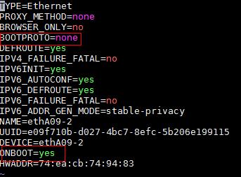
[root@sna001 /]# vi /etc/sysconfig/network-scripts/ifcfg-ens34
3. Set the BOOTPROTO field to none to not specify a boot-up protocol and set the ONBOOT field to yes to activate the NIC at system startup.
Figure 1 Modifying the configuration file of a NIC
4. Execute the ifdown and ifup commands in sequence to reboot the NIC.
[root@sna001 /]# ifdown ens34
[root@sna001 /]# ifup ens34
5. Execute the ifconfig command to verify that the NIC is in up state.
Planning the networks
Network planning
Three types of networks can be created, including Calico network, MACVLAN network, and OVS-DPDK network.
The Calico network is an internal network used for container interactions. The network segment of the Calico network is the IP address pool set for containers when the SNA Installer cluster is deployed. The default network segment is 177.177.0.0. You do not need to configure an address pool for the Calico network when installing and deploying the controller. The Calico network and MACVLAN network can use the same NIC.
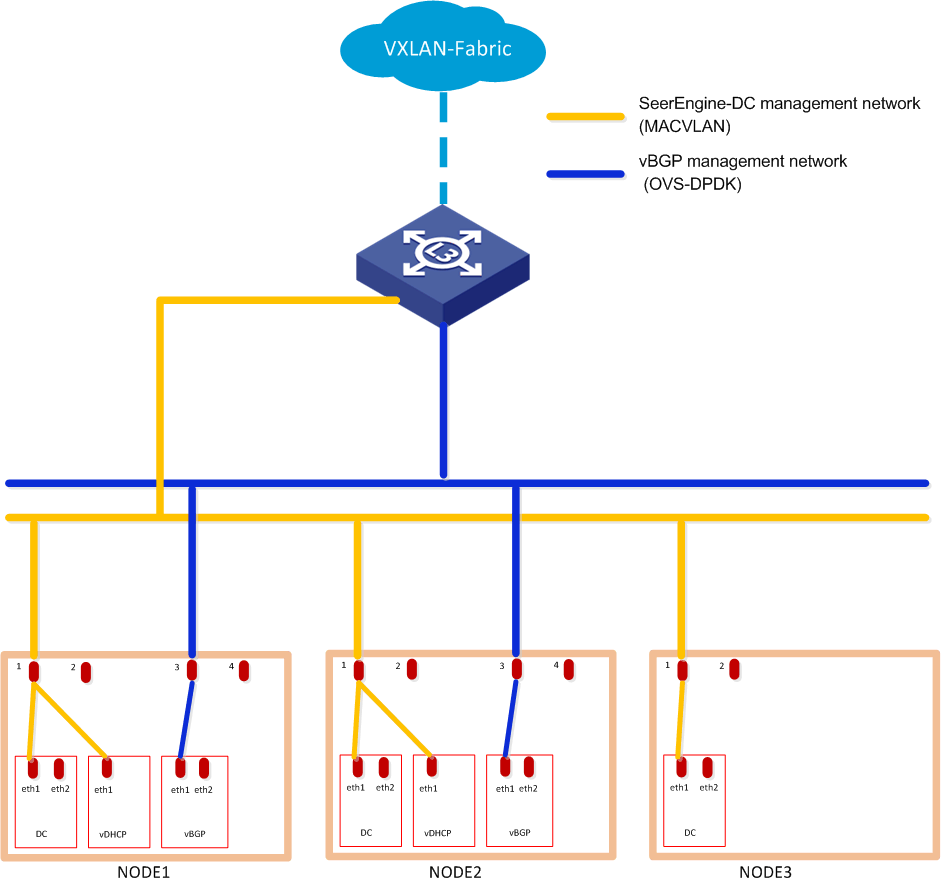
Before deploying the controller, plan the address pools for the MACVLAN and OVS-DPDK networks in advance. Both networks are used as management networks. The SeerEngine-DC and vDHCP components can use the same MACVLAN network as the management network. The vBGP component uses the OVS-DPDK network as the management network.
vBGP is an optional component. To not deploy vBGP, configure only the MACVLAN network. To deploy vBGP, configure both MACVLAN and OVS-DPDK networks.
Figure 2 Network planning for the cloud data center scenario (to deploy vBGP only)
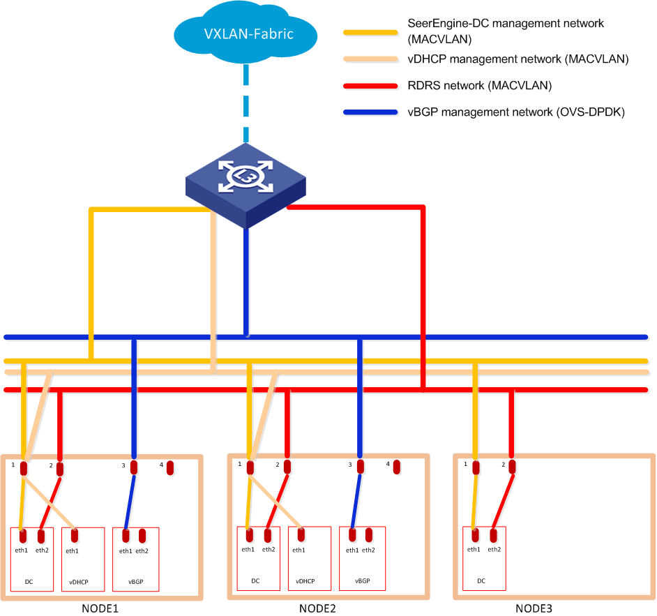
To deploy RDRS, follow these guidelines to plan the networks:
· Use the same IP address for the vDHCP components at the primary and backup sites.
· As a best practice, configure separate MACVLAN-type management networks for the SeerEngine-DC and vDHCP components. If the two MACVLAN networks share a NIC, configure VLANs to isolate the networks.
· Configure a separate MACVLAN network as the RDRS network. The RDRS network is used to synchronize data between the primary and backup sites. Ensure connectivity between the RDRS networks at the primary site and backup site. If the RDRS and management networks use the same NIC, configure VLANs to isolate the networks. As a best practice, use a separate NIC for the RDRS network as shown in Figure 3.
Figure 3 Network planning for the cloud data center scenario (to deploy vBGP and RDRS)
IP address planning
To calculate the IP addresses required for a MACVLAN or OVS-DPDK subnet.
1. Use Table 6 as a best practice to calculate the number of IP addresses required for each component team.
Table 5 Number of IP addresses required for each component team
|
Component |
Maximum team members |
Default team members |
Number of IP addresses |
|
SeerEngine-DC |
32 |
3 |
Number of team members + 1 (team IP) |
|
vDHCP |
2 |
2 |
Number of team members + 1 (team IP) |
|
vBGP |
2 |
2 |
Number of team members + 1 (team IP) |
2. Calculate the number of IP addresses required for the subnet. The following calculations assume that each component team has a default number of team members.
¡ MACVLAN subnet
- Without RDRS deployed: (1*3+1) + (1*2+1) = 7.
- With RDRS deployed: (2*3+1) + (1*2+1) = 10.
¡ OVS-DPDK subnet: (1*2+1) = 3.
Table 7 shows an example for IP address planning.
Table 6 IP address planning for the non-RDRS scenario
|
Item |
IP addresses |
|
MACVLAN subnet (management network) |
10.0.234.0/24 (gateway 10.0.234.254) |
|
MACVLAN network address pool (management network) |
10.0.234.6 to 10.0.234.38 |
|
MACVLAN subnet (RDRS network) |
192.168.0.0/16 (gateway 192.168.160.1) |
|
MACVLAN network address pool (RDRS network) |
192.168.160.1 to 192.168.160.32 |
|
OVS-DPDK subnet |
11.0.234.0/24 (gateway 11.0.234.254) |
|
OVS-DPDK network address pool |
11.0.234.1 to 11.0.234.32 |
Table 7 IP address planning for the RDRS scenario
|
Item |
IP addresses |
|
MACVLAN subnet (SeerEngine-DC) |
10.0.234.0/24 (gateway 10.0.234.254) |
|
MACVLAN network address pool (SeerEngine-DC) |
10.0.234.6 to 10.0.234.38 |
|
MACVLAN subnet (vDHCP) |
10.0.233.0/24 (gateway 10.0.233.254) |
|
MACVLAN network address pool (vDHCP) |
10.0.233.6 to 10.0.233.38 |
|
MACVLAN subnet (RDRS network) |
192.168.0.0/16 (gateway 192.168.160.1) |
|
MACVLAN network address pool (RDRS network) |
192.168.160.1 to 192.168.160.32 |
|
OVS-DPDK subnet |
11.0.234.0/24 (gateway 11.0.234.254) |
|
OVS-DPDK network address pool |
11.0.234.1 to 11.0.234.32 |
|
|
IMPORTANT: · The MACVLAN and OVS-DPDK subnets are on different network segments. You must configure routing entries on the connected switches to enable Layer 3 communication between the SeerEngine-DC management network and vBGP management network. · If two MACVLAN networks share a NIC, configure the port on the switch that connects to the server as a trunk port, configure the port on the server that connects to the switch to work in hybrid mode, and configure VLAN and VLAN interface settings on the switch. · For RDRS to operate correctly, make sure the IP addresses of RDRS networks at the primary and backup sites do not overlap with the IP address of the SeerEngine-DC component, and the vDHCP components at the primary and backup sites use a same IP address. |
Deploying the controller
1. Log in to SNA Center. Click System > Settings.
2. On the top navigation bar, click Components, and then select Components from the navigation pane.
3. Click Upload to upload the installation package and then click Next.
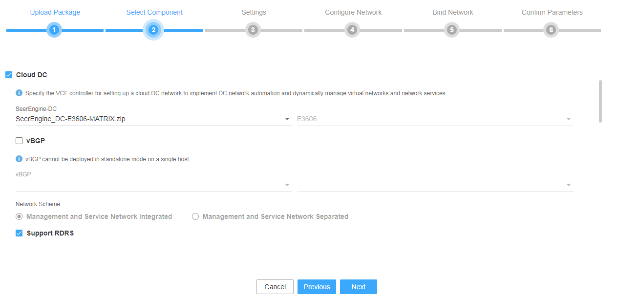
4. Select Cloud DC. To deploy the vBGP component simultaneously, select vBGP and select a network scheme for vBGP deployment. For the controller to support RDRS, select Support RDRS. Then click Next.
Figure 4 Selecting components
5. On the Settings tab, you can configure parameters for the components. The controller does not support parameter configuration on this tab. Click Next directly.
6. Configure the MACVLAN and OVS-DPDK networks and add the uplink interfaces according to the network plan in "Planning the network." If you are not to deploy vBGP, you only need to configure MACVLAN networks.
To deploy RDRS, configure the network settings as follows:
¡ Configure a MACVLAN management network separately for the SeerEngine-DC and vDHCP components.
¡ Specify a VLAN for the MACVLAN network configured for the vDHCP component, and make sure the VLAN ID is different from the PVID.
¡ Add the same uplink interface for the two MACVLAN networks.
¡ Configure a separate MACVLAN network as the RDRS network.
Figure 5 Configuring a MACVLAN management network for the SeerEngine-DC component
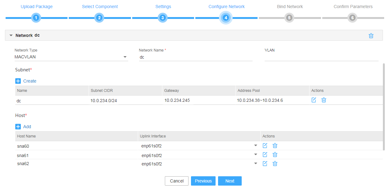
Figure 6 Configuring a MACVLAN management network for the vDHCP component
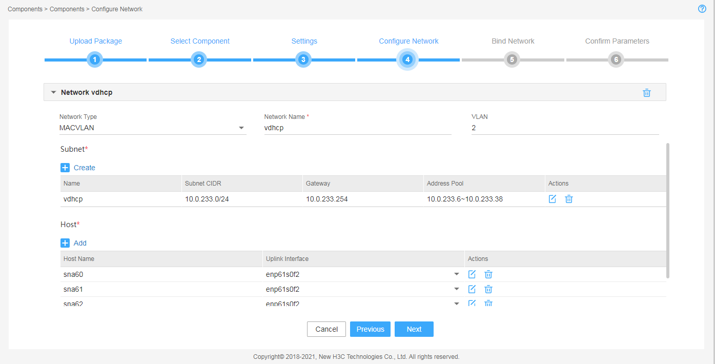
Figure 7 Configuring an RDRS network
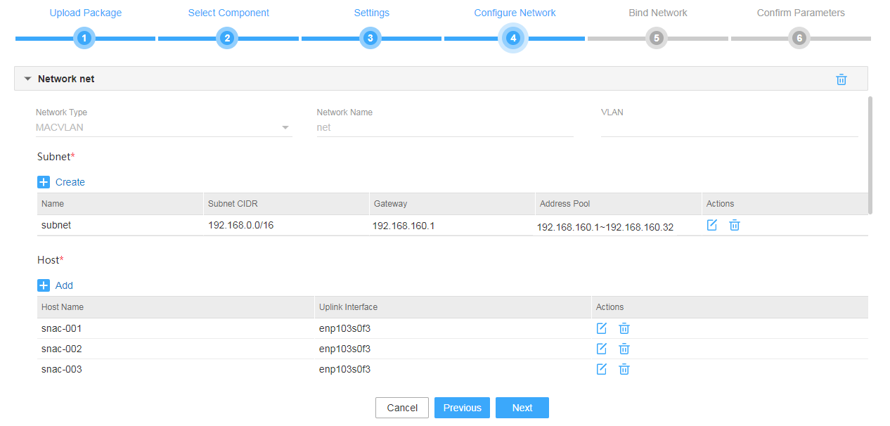
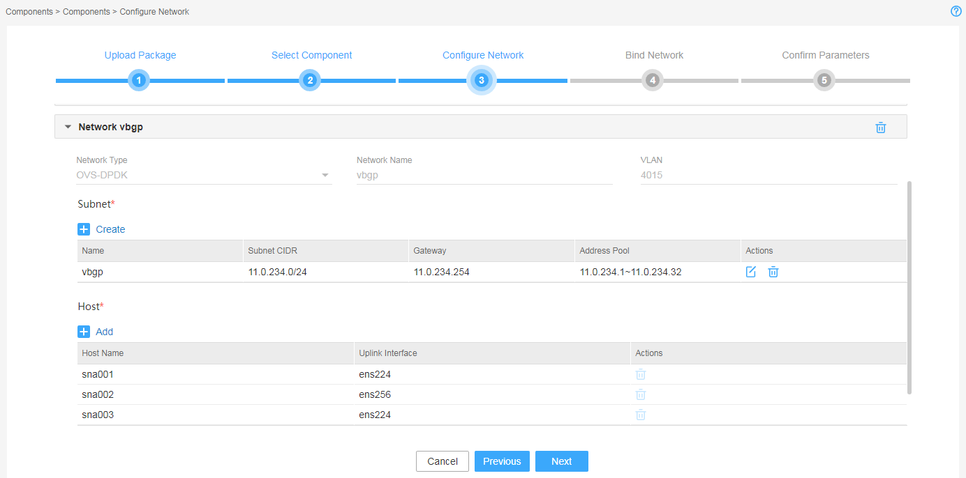
Figure 8 Configuring an OVS-DPDK network
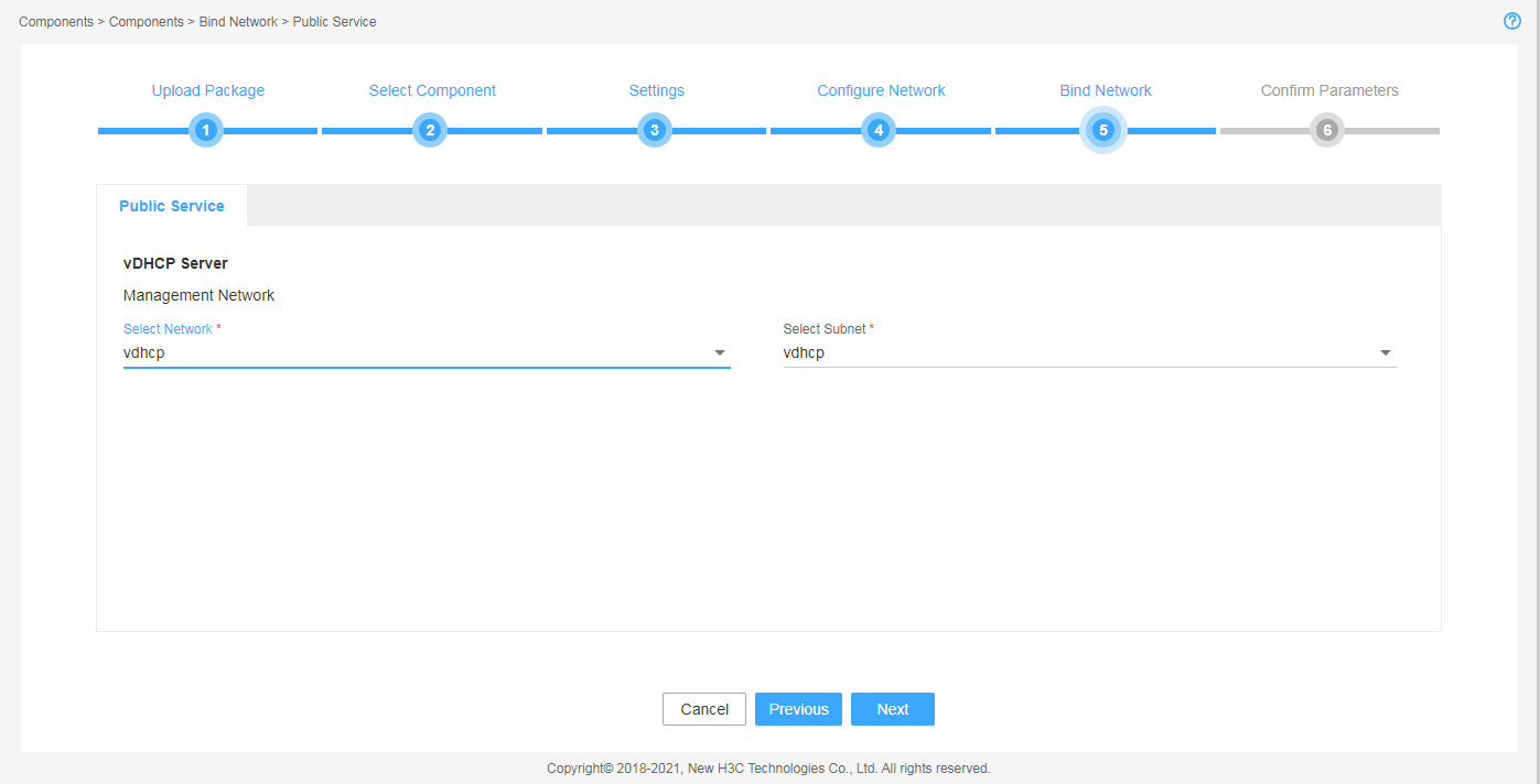
7. Bind networks to the components, assign IP address to the components, and then click Next.
Figure 9 Binding networks to components (1)
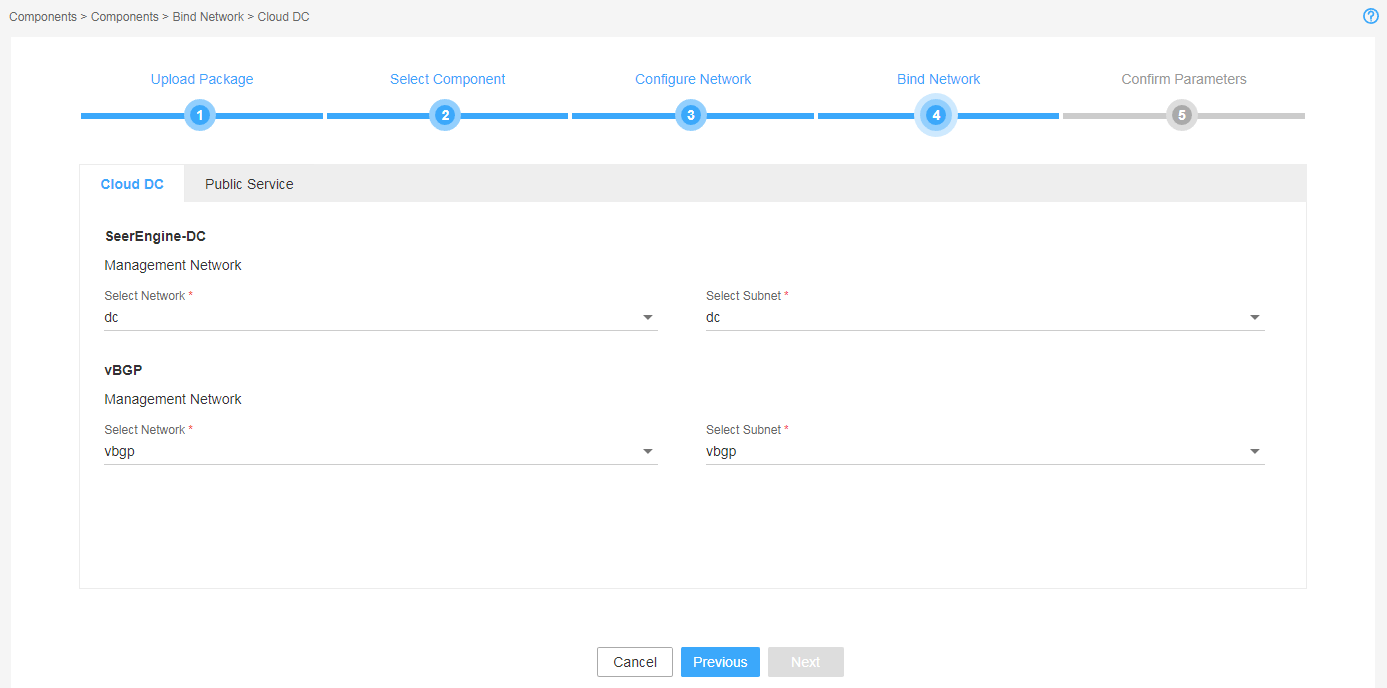
Figure 10 Binding networks to components (2)
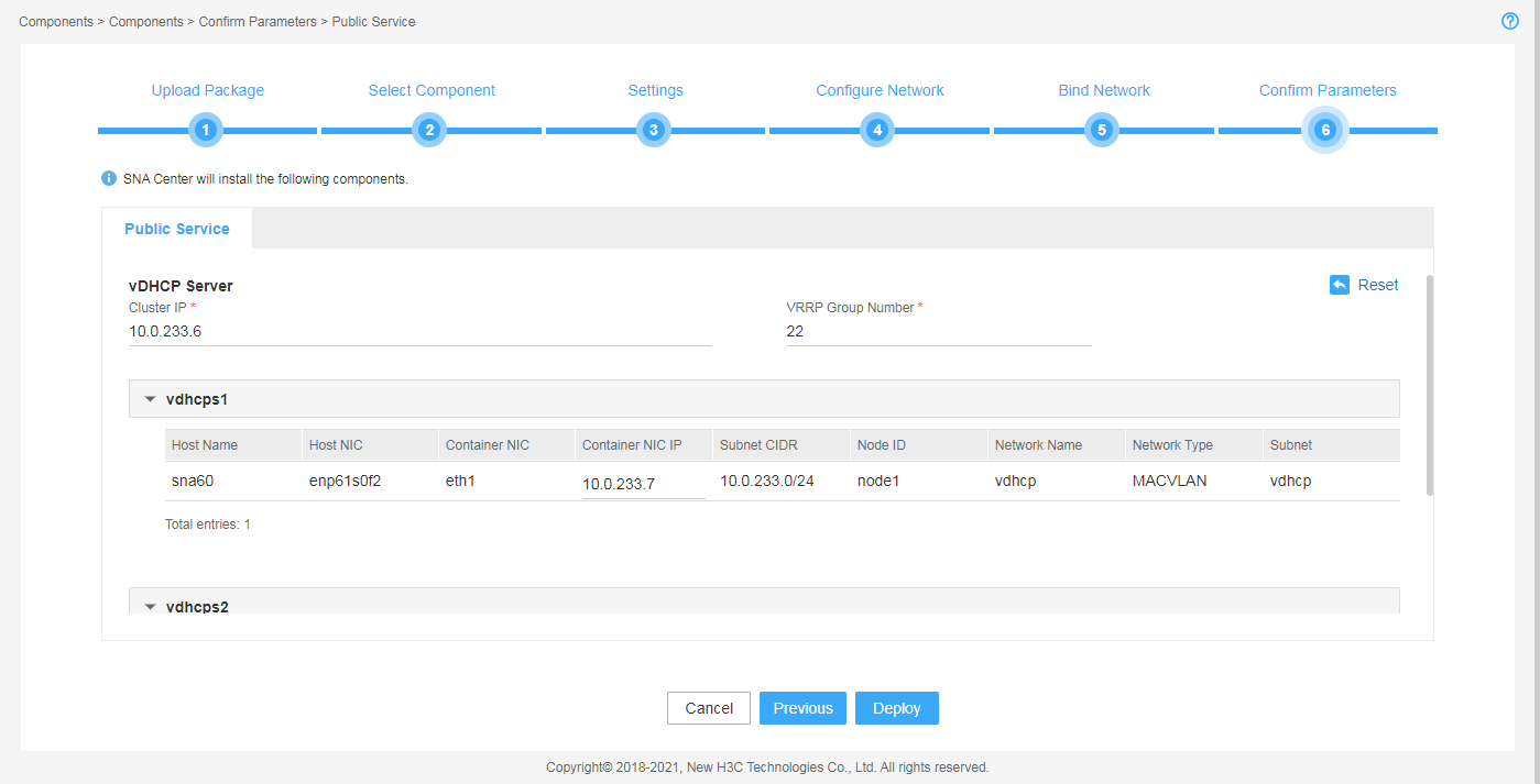
8. On the Confirm Parameters tab, verify network information, configure the RDRS status, and specify a VRRP group ID for the components.
A component automatically obtains an IP address from the IP address pool of the subnet bound to it. To modify the IP address, click Modify and then specify another IP address for the component. The IP address specified must be in the IP address range of the subnet bound to the component.
You are required to configure the RDRS status for the controller if you have selected the Support RDRS option for it:
¡ Select Primary from the Status in RDRS list for a controller at the primary site.
¡ Select Backup from the Status in RDRS list for a controller at the backup site.
If vDHCP and vBGP components are to be deployed, you are required to specify a VRRP group ID in the range of 1 to 255 for the components. The VRRP group ID must be unique within the same network.
Figure 11 Confirming the parameters for the controller (1)
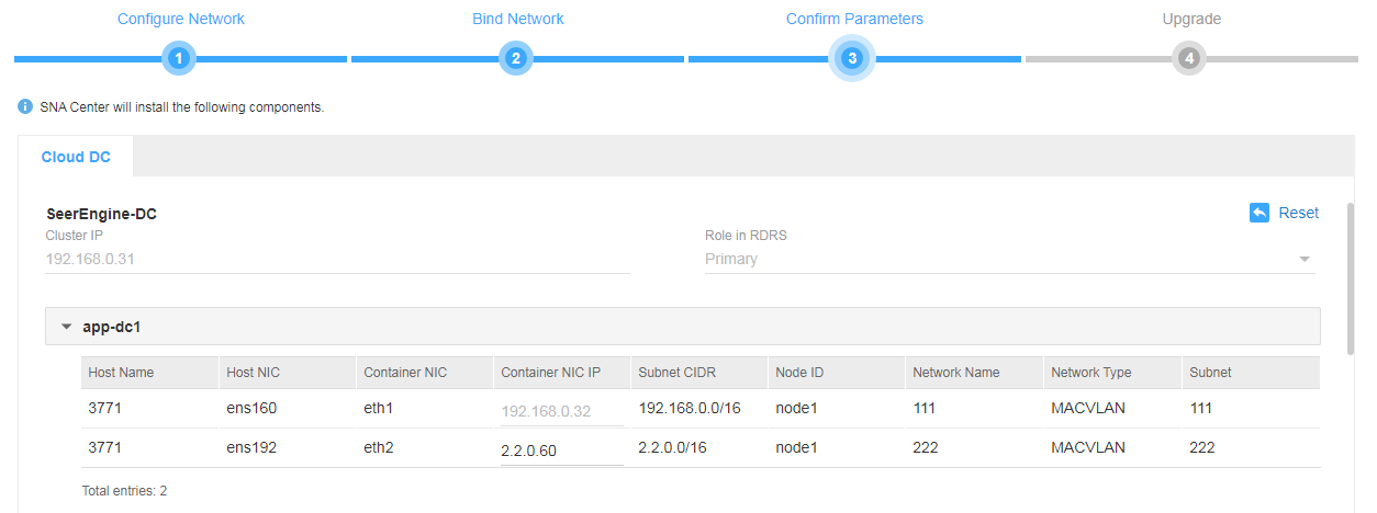
Figure 12 Confirming the parameters for the vBGP component (2)
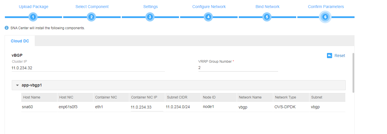
Figure 13 Confirming the public service parameters
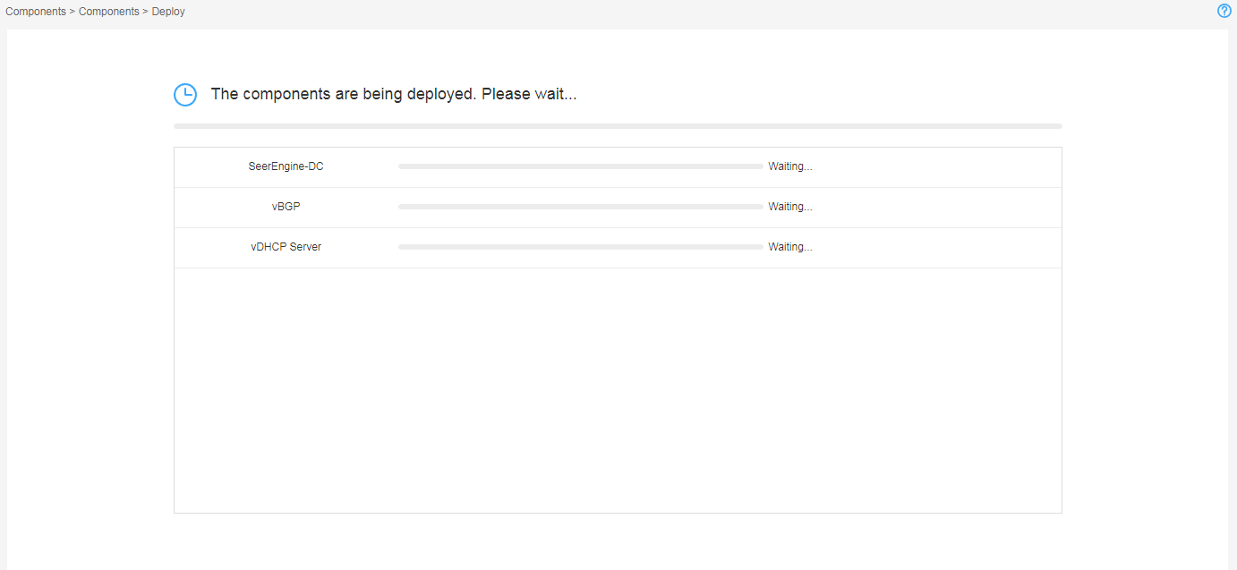
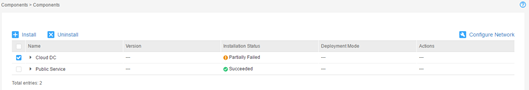
9. Click Deploy.
Figure 14 Components in deployment
Accessing the controller
The controller runs on SNA Center. To access the controller, first log in to SNA Center.
To log in to the controller:
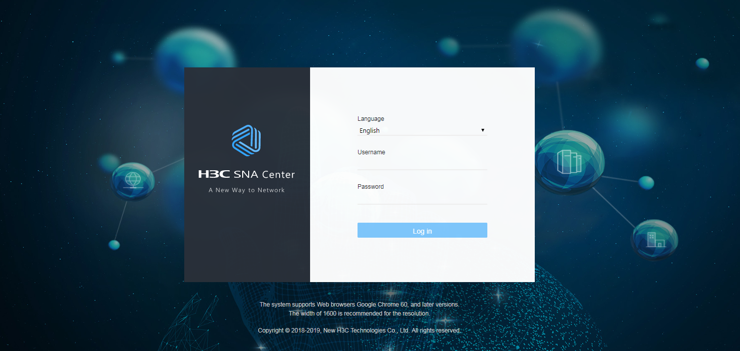
1. Enter the address for accessing SNA Center in the address bar and then press Enter.
By default, the login address is https://sna_center_ip_address:10443/portal. However, if you have specified the HTTP login protocol during the SNA Center deployment process, the login address is http://sna_center_ip_address:10080/portal.
¡ sna_center_ip_address represents the northbound virtual IP address of the SNA Installer cluster.
¡ 10443 and 10080 are port numbers.
2. Enter the username and password, and then click Log in.
The default username is admin and the default password is admin@123.
Figure 15 SNA Center login page
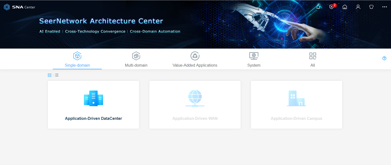
3. On the SNA Center home page, click Application-Driven DataCenter.
Figure 16 SNA Center home page
Registering and installing licenses
Registering and installing licenses for SNA Center
For the SNA Center license registration and installation procedure, see H3C SNA Center Installation and Components Deployment Guide.
Registering and installing licenses for the controller
After you install the controller, you can use its complete features and functions for a 180-day trial period. After the trial period expires, you must get the controller licensed.
Installing the activation file on the license server
For the activation file request and installation procedure, see H3C Software Products Remote Licensing Guide.
Obtaining licenses
1. Log in to SNA Center and click Application-Driven DataCenter.
2. Click Settings in the System area. From the navigation pane, select License.
3. Configure the parameters for the license server as described in Table 11.
Table 8 License server parameters
|
Item |
Description |
|
IP address |
Specify the IP address configured on the license server used for internal communication in the cluster. |
|
Port number |
Specify the service port number of the license server. The default value is 5555. |
|
Username |
Specify the client username configured on the license server. |
|
Password |
Specify the client password configured on the license server. |
4. Click Connect to connect the controller to the license server.
The controller will automatically obtain licensing information after connecting to the license server.
Backing up and restoring the controller configuration
|
|
IMPORTANT: If the version of the controller is upgraded from a patch, you must re-use the patch package to upgrade the component to that version after backing up and restoring the controller. |
You can back up and restore the controller configuration on SNA Center. For the procedures, see H3C SNA Center Installation and Component Deployment Guide.
Upgrading the controller
|
|
CAUTION: · The upgrade might cause service interruption. Be cautious when you perform this operation. · Before upgrading or scaling out SNA Center or the controller, specify the manual switchover mode for the RDRS if the RDRS has been created. · Do not upgrade the controllers on the primary and backup sites simultaneously if the RDRS has been created. Upgrade the controller on a site first, and upgrade the controller on another site after data is synchronized between the two sites. · In an RDRS system, the IP addresses of the vDHCP components at the primary and backup sites must be the same. As a best practice, remove and reinstall the vDHCP component after upgrading the controller to support RDRS in an environment where the vDHCP component has been deployed. |
The controller can be upgraded on SNA Center with the configuration retained.
You can use the installation package or patch package to upgrade the controller.
To upgrade the controller:
1. Log in to SNA Center. Click System > Settings.
2. On the top navigation bar, click Components, and then select Components from the navigation pane.
3. Click the right chevron button ![]() for the controller to expand controller information, and then click the upgrade icon
for the controller to expand controller information, and then click the upgrade icon ![]() .
.
4. Continue the upgrade procedure as guided by the system.
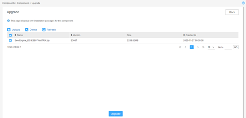
¡ If the controller already supports RDRS, the upgrade page is displayed. Upload and select the installation package or patch package and then click Upgrade.
Figure 17 Component upgrade page
¡ If the controller does not support RDRS, the system displays a confirmation dialog box with a Support RDRS option.
Figure 18 Support RDRS option
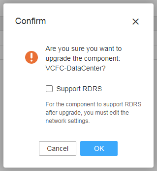
- If you leave the Support RDRS option unselected, the upgrade page is displayed. Upload and select the installation package and then click Upgrade.
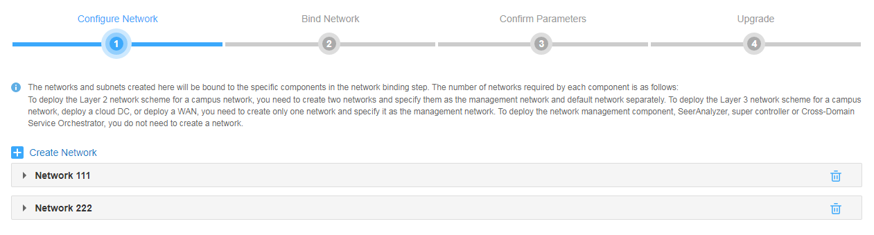
- If you select the Support RDRS option, perform the following steps:
# On the Configure Network tab, create a MACVLAN network as the RDRS network. Make sure the RDRS network and the management network are on different network segments.
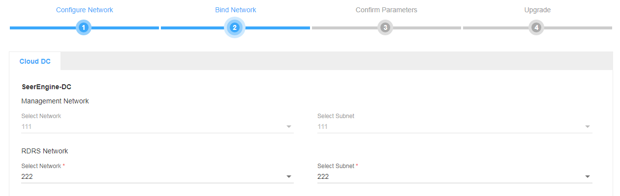
# On the Bind Network tab, bind the controller to the corresponding RDRS network and subnet, and then click Next.
# On the Confirm Parameters tab, verify that the IP addresses assigned to the RDRS network are correct, and then click Next.

# On the Upgrade tab, upload and select the installation package or patch package, and then click Upgrade.
5. If the upgrade fails, click Roll Back to roll back to the previous version.
Uninstalling the controller
1. Log in to SNA Center. Click System > Settings.
2. On the top navigation bar, click Components, and then select Components from the navigation pane.
3. Uninstall the controller.
¡ To
uninstall the installation package and patch package simultaneously, click the ![]() icon on the left of the controller name
and then click
icon on the left of the controller name
and then click ![]()
Figure 19 Uninstalling the controller
¡ To uninstall a patch only, click the ![]() icon
on the left of the controller
name, select the patch package, and then click
icon
on the left of the controller
name, select the patch package, and then click ![]() . You cannot
uninstall a patch together with other components or patches.
. You cannot
uninstall a patch together with other components or patches.
Scaling out or in the controller
As a best practice, deploy the controller in cluster mode. In cluster mode, you can scale out the controller by adding more worker nodes or scale in the controller by deleting worker nodes.
Scaling out the controller
Before scaling out the controller, make sure worker nodes have been added to the SNA Installer cluster. For more information, see H3C SNA Center Installation and Components Deployment Guide.
To scale out the controller:
1. Log in to SNA Center. Click System > Settings.
2. Click Components on the top navigation bar and then select Components from the navigation pane.
3. Click ![]() next to the controller,
and then click the Scale Out icon
next to the controller,
and then click the Scale Out icon ![]() in
the Actions column.
in
the Actions column.
4. Select the hosts on which you want to install the controller and select the uplink interfaces for the hosts. Review the scale-out settings, and then click OK.
Scaling in the controller
You can scale in the controller by deleting worker nodes in the cluster.
To scale in the controller:
1. Remove a scaled-out instance:
Only an instance scaled out from a cluster can be removed.
a. Log in to SNA Center. Click System > Settings
b. Click Components on the top navigation bar and then select Components from the navigation pane.
c. Identify the instance .Click the ![]() icon for the instance and then click OK in the dialog box that opens.
icon for the instance and then click OK in the dialog box that opens.
Removing a deployed instance might affect the services. Back up the instance before removing it.
2. Remove the network binding:
a. Click Components on the top navigation bar and then select Components from the left navigation pane.
b. Click Configure Network in the upper right corner.
c. Remove the binding between the host and uplink interface on the worker node to be deleted.
3. Delete the worker node:
a. Click Deploy on the top navigation bar and then select Cluster from the navigation pane.
b. In the Worker node area,
click the ![]() icon for the worker node to be deleted.
icon for the worker node to be deleted.
c. Select Delete from the list.
RDRS
About RDRS
A remote disaster recovery system (RDRS) provides disaster recovery services between the primary and backup sites. The controllers at the primary and backup sites back up each other. When the RDRS is operating correctly, data is synchronized between the site providing services and the peer site in real time. When the service-providing site becomes faulty because of power, network, or external link failure, the peer site immediately takes over to ensure service continuity.
The RDRS supports the following switchover modes:
· Manual switchover—In this mode, the RDRS does not automatically monitor state of the controllers on the primary or backup site. You must manually control the controller state on the primary and backup sites by specifying the Switch to Primary or Switch to Backup actions. This mode requires deploying SNA Center of the same version on the primary and backup sites.
· Auto switchover with arbitration—In this mode, the RDRS automatically monitors state of the controllers. Upon detecting a controller or SNA Center failure (because of site power or network failure), the RDRS automatically switches controller state at both sites by using the third-party arbitration service. This mode also supports manual switchover. To use this mode, you must deploy SNA Center of the same version at the primary and backup sites and the third-party arbitration service.
The third-party arbitration service can be deployed on the same server as the primary or backup site. However, when the server is faulty, the third-party arbitration service might stop working. As a result, RDRS auto switchover will fail. As a best practice, configure the third-party arbitration service on a separate server.
Creating an RDRS
1. Deploy the primary and backup sites and a third-party site.
2. Deploy RDRS on the controllers.
3. Create an RDRS.
Deploying the primary and backup sites and a third-party site
Restrictions and guidelines
Follow these restrictions and guidelines when you deploy the primary and backup sites and a third-party site:
· The SNA Center version, access protocol, username and password, and IP version of the primary and backup sites must be the same.
· The arbitration service package on the third-party site must match the SNA Center version on the primary and backup sites.
· To use the auto switchover with arbitration mode, you must deploy a standalone SNA Installer as the third-party site, and deploy arbitration services on the site.
· To use the allowlist feature in an RDRS scenario, you must add the IP addresses of all nodes on the backup site to the allowlist on the primary site, and add the IP addresses of all nodes on the primary site to the allowlist on the backup site.
· To avoid service failure during a primary/backup switchover, you must configure the same IP address for the vDHCP components at the primary and backup sites.
Procedure
This procedure uses a separate server as the third-party site and deploys SNA Installer in standalone mode on this site.
To deploy the primary and backup sites and a third-party site:
1. Deploy SNA Installer on primary and backup sites and the third-party site. For the deployment procedure, see H3C SNA Center Installation and Components Deployment Guide.
2. Deploy SNA Center on primary and backup sites. Specify the same NTP server for the primary and backup sites. For the deployment procedure, see H3C SNA Center Installation and Components Deployment Guide.
3. Deploy arbitration services on the third-party site.
a. Log in to SNA Installer.
b. Select Deploy from the top navigation bar and then select Application from the left navigation pane.
c. Click Upload to upload the arbitration service package SeerEngine_DC_ARBITRATOR-version.zip.
d. Click Next and then configure the parameters.
e. Click Deploy.
Deploying RDRS on the controllers
Restrictions and guidelines
If the controller installed on the primary
site does not support disaster recovery, click the ![]() icon
on the controller management page to upgrade it to support disaster recovery.
For the upgrade procedure, see "Upgrading the controller."
icon
on the controller management page to upgrade it to support disaster recovery.
For the upgrade procedure, see "Upgrading the controller."
If the controller installed on the specified backup site does not support disaster recovery or is not in backup state, remove the controller and install it again.
The SeerEngine-DC installation package name and SeerEngine-DC version must be the same on the primary and backup sites.
Procedure
To deploy RDRS on the controller, select the Support RDRS option when deploying the controller and configure the primary and backup RDRS state for it. For the controller deployment procedure, see "Deploying the controller."
Creating an RDRS
Restrictions and guidelines
Ensure network connectivity between the primary and backup sites during the RDRS creation process. If the creation failures, first check the network connectivity between the primary and backup sites.
Do not create an RDRS at the primary and backup sites simultaneously.
You cannot back up or restore data on the RDRS configuration page, including the primary or backup site name, primary or backup site IP address, backup site username and password, and third-party site IP address.
After an RDRS is created, you cannot change the internal virtual IP of the SNA Installer cluster at the primary and backup sites and the node IPs.
Procedure
1. Click System on the top navigation bar and then select RDRS from the navigation pane.
2. In the Site Settings area, configure the primary, backup, and third-party site settings, and specify the switchover mode.
3. Click Connect.
If the heartbeat link is successfully set up, the RDRS site settings have been configured successfully.
After the sites are built successfully, the backup site will automatically synchronize its user, log, and backup and restore settings to the primary site, with the exception of the log content.
4. In the Disaster Recovery Components area, click Add to configure disaster recovery components.
