- Table of Contents
- Related Documents
-
| Title | Size | Download |
|---|---|---|
| 02-Hardware Information and Specifications | 1.40 MB |
1 Product models and technical specifications
Product models
This document is applicable to the following Ethernet switches:
|
Switch series |
Switch model |
Product code |
|
S6826 switch series |
S6826-48Y8C |
LS-6826-48Y8C |
|
S9826 switch series |
S9826-32C |
LS-9826-32C |
Technical specifications
Table1-1 Technical specifications
|
Item |
S6826-48Y8C |
S9826-32C |
|
Dimensions (H × W × D) |
43.6 × 440 × 460 mm (1.72 × 17.32 × 18.11 in) |
43.6 × 440 × 540 mm (1.72 × 17.32 × 21.26 in) |
|
Weight |
≤ 15 kg (33.07 lb) |
≤ 15 kg (33.07 lb) |
|
Console port |
· 1 × mini USB console port · 1 × serial console port |
· 1 × mini USB console port · 1 × serial console port |
|
Management Ethernet port |
· 1 × 10M/100M/1000M BASE-T copper port · 1 × SFP port |
· 1 × 10M/100M/1000M BASE-T copper port · 1 × SFP port |
|
USB port |
1 |
1 |
|
SFP port |
2 |
N/A |
|
SFP+ port |
N/A |
2 |
|
SFP28 port |
48 |
N/A |
|
QSFP28 port |
8 |
32 |
|
Fan tray slot |
5 |
6 |
|
Power supply slot |
2 |
2 |
|
Static power consumption (For the conditions under which static power consumptions are measured, see Table1-2.) |
· Single AC input: 134 W · Dual AC inputs: 145 W · Single DC input: 126 W · Dual DC inputs: 141 W |
· Single AC input: 162 W · Dual AC inputs: 174 W · Single DC input: 153 W · Dual DC inputs: 164 W |
|
Typical power consumption (For the conditions under which typical power consumptions are measured, see Table1-2.) |
· Single AC input: 165 W · Dual AC inputs: 176 W · Single DC input: 160 W · Dual DC inputs: 169 W |
· Single AC input: 218 W · Dual AC inputs: 225 W · Single DC input: 214 W · Dual DC inputs: 215 W |
|
Maximum power consumption (For the conditions under which maximum power consumptions are measured, see Table1-2.) |
· Single AC input: 305 W · Dual AC inputs: 316 W · Single DC input: 301 W · Dual DC inputs: 311 W |
· Single AC input: 417 W · Dual AC inputs: 423 W · Single DC input: 412 W · Dual DC inputs: 418 W |
|
Sound pressure level at 27°C (80.6°F) |
62.4 dB(A) |
62.9 dB(A) |
|
Chassis leakage current compliance |
· UL60950-1 · EN60950-1 · IEC60950-1 · GB4943 |
|
|
Operating temperature |
0°C to 45°C (32°F to 113°F) |
|
|
Operating relative humidity |
5% to 95%, noncondensing |
|
|
Fire resistance compliance |
· UL60950-1 · EN60950-1 · IEC60950-1 · GB4943 |
|
Table1-2 Power consumption measurement conditions
|
Item |
Minimum power consumption |
Typical power consumption |
Maximum power consumption |
|
Configuration |
· Two power supplies · No transceiver modules or cables installed in ports |
· Two power supplies · Fully configured with cables |
· Two power supplies · Fully configured with transceiver modules |
|
Load |
No |
50% load |
100% load |
2 Chassis views
S6826-48Y8C
|
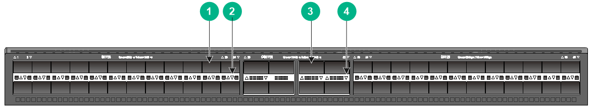
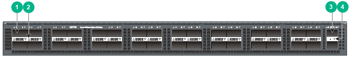
(1) SFP28 port |
(2) SFP28 port LED |
|
(3) QSFP28 port |
(4) QSFP28 port LED |
|
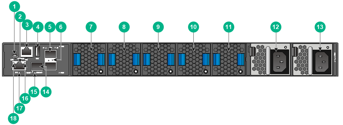
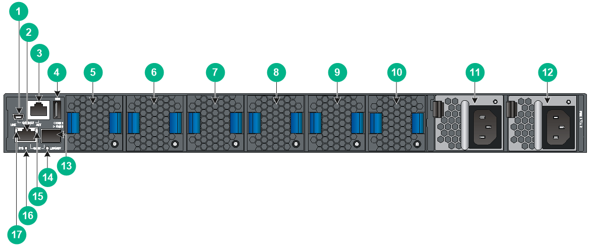
(1) Mini USB console port |
(2) Copper management Ethernet port |
|
(3) Serial console port |
(4) USB port |
|
(5) SFP port |
(6) SFP port LED |
|
(7) Fan tray 1 |
(8) Fan tray 2 |
|
(9) Fan tray 3 |
(10) Fan tray 4 |
|
(11) Fan tray 5 |
(12) Power supply 1 |
|
(13) Power supply 2 |
(14) Fiber management Ethernet port |
|
(15) Fiber management Ethernet port LED (LINK/ACT) |
|
|
(16) Copper Management Ethernet port LED (ACT) |
(17) System status LED (SYS) |
|
(18) Copper management Ethernet port LED (LINK) |
|
The S6826-48Y8C switch comes with power supply slot PWR1 empty and power supply slot PWR2 installed with a filler panel. You can install one or two power supplies for the switch as needed. In Figure2-2, two LSVM1AC650 power supplies are installed in the power supply slots.
The S6826-48Y8C switch comes with the five fan tray slots empty. You must install five fan trays of the same model for the switch. In Figure2-2, five LSWM1FANSA fan trays are installed in the fan tray slots.
The S6826-48Y8C switch comes with a dust plug in each fiber Ethernet port. To use a fiber Ethernet port, first remove the dust plug. In Figure2-1, the dust plugs have been removed from the fiber Ethernet ports.
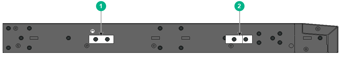
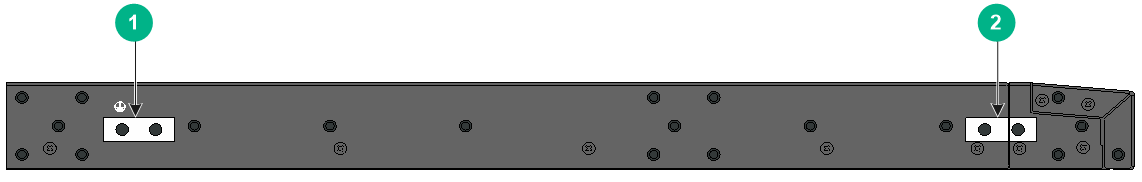
Figure2-3 Left panel
|
(1) Primary grounding point |
(2) Auxiliary grounding point |
S9826-32C
|
(1) QSFP28 port |
(2) QSFP28 port LED |
|
(3) SFP+ port |
(4) SFP+ port LED |
|
(1) Mini USB console port |
(2) Copper management Ethernet port |
|
(3) Serial console port |
(4) USB port |
|
(5) Fan tray 1 |
(6) Fan tray 2 |
|
(7) Fan tray 3 |
(8) Fan tray 4 |
|
(9) Fan tray 5 |
(10) Fan tray 6 |
|
(11) Power supply 1 |
(12) Power supply 2 |
|
(13) Fiber management Ethernet port |
|
|
(14) Fiber Management Ethernet port LED (LINK/ACT) |
|
|
(15) Copper management Ethernet port LED (ACT) |
(16) System status LED (SYS) |
|
(17) Copper management Ethernet port LED (LINK) |
|
The S9826-32C switch comes with power supply slot PWR1 empty and power supply slot PWR2 installed with a filler panel. You can install one or two power supplies for the switch as needed. In Figure2-5, two LSVM1AC650 power supplies are installed in the power supply slots.
The S9826-32C switch comes with the six fan tray slots empty. You must install six fan trays of the same model for the switch. In Figure2-5, six LSWM1FANSA fan trays are installed in the fan tray slots.
The S9826-32C switch comes with a dust plug in each fiber Ethernet port. To use a fiber Ethernet port, first remove the dust plug. In Figure2-4, the dust plugs have been removed from the fiber Ethernet ports.
Figure2-6 Left panel
|
(1) Primary grounding point |
(2) Auxiliary grounding point |
3 Removable components
Removable components available for the switches
The switches use modular design. Table3-1 describes the removable components available for the switches.
Table3-1 Removable components available for the switches
|
Removable components |
S9826-32C |
S6826-48Y8C |
|
Removable power supplies |
||
|
LSVM1AC650 |
Yes |
Yes |
|
LSVM1DC650 |
Yes |
Yes |
|
Removable fan trays |
||
|
LSWM1FANSA |
Yes |
Yes |
|
LSWM1FANSAB |
Yes |
Yes |
The switch can operate correctly with only one power supply. You can install two power supplies on the switch for 1+1 redundancy.
To ensure adequate heat dissipation, make sure the switch is fully configured with fan trays of the same model.
Power supplies
|
|
WARNING! When the switch has power supplies in redundancy, you can replace a power supply without powering off the switch. Make sure the power supply to be replaced is powered off before you replace it. |
Table3-2 Power supply specifications
|
Power supply model |
Specifications |
Remarks |
|
LSVM1AC650 |
· Rated input voltage: 100 VAC to 240 VAC @ 50 Hz or 60 Hz · Max input voltage: 90 VAC to 264 VAC @ 47 Hz to 63 Hz · Max output power: 650 W · Melting current of the fuse: 10 A/250 V |
For more information about the power supplies, see H3C LSVM1AC650 & LSVM1DC650 Power Modules User Manual. |
|
LSVM1DC650 |
· Rated input voltage: –40 VDC to –60 VDC · Max input voltage: –40 VDC to –72 VDC · Max output power: 650 W · Melting current of the fuse: 30 A/250 V |
Fan trays
Table3-3 Fan tray specifications
|
Fan tray model |
Item |
Specifications |
|
· LSWM1FANSA (from the power supply side to the port side) · LSWM1FANSAB (from the port side to the power supply side) |
Dimensions |
40.6 × 42.5 × 118.7 mm (1.60 × 1.67 × 4.67 in) |
|
Fan speed |
21000 R.P.M |
|
|
Max airflow |
35 CFM |
|
|
Input voltage |
12 V |
|
|
Maximum power consumption |
30 W |
|
|
Documentation reference |
H3C LSWM1FANSA & LSWM1FANSAB Fan Tray User Guide |
4 Ports and LEDs
As a best practice, use H3C transceiver modules and cables for the switch. H3C transceiver modules and cables are subject to change over time. For the most up-to-date list of H3C transceiver modules and cables, contact H3C Support or marketing staff. For information about the specifications and views of H3C transceiver modules and cables, see H3C Transceiver Modules User Guide.
Ports
Console port
The switch has two console ports: one serial console port and one mini USB console port. If you connect the two ports each to a configuration terminal, only one takes effect.
Table4-1 Console port specifications
|
Item |
Console port |
Mini USB console port |
|
Connector type |
RJ-45 |
USB mini-Type B |
|
Compliant standard |
EIA/TIA-232 |
USB 2.0 |
|
Transmission baud rate |
9600 bps (default) to 115200 bps |
|
|
Services |
· Provides connection to an ASCII terminal. · Provides connection to the serial port of a local or remote (through a pair of modems) PC running terminal emulation program. |
· Provides connection to an ASCII terminal. · Provides connection to the USB port of a local PC running terminal emulation program. |
Management Ethernet port
The switch has two management Ethernet ports: one copper management port and one SFP management port. You can connect the ports to a local PC for software loading and debugging or to a remote management station for remote management.
Table4-2 Management Ethernet port specifications
|
Item |
Specification |
|
Connector type |
· 10/100/1000BASE-T management port: RJ-45. · SFP management port: LC. |
|
Port transmission rate |
· 10/100/1000BASE-T management port: ¡ 10/100 Mbps, half/full duplex, MDI/MDI-X auto-sensing. ¡ 1000 Mbps, full duplex, MDI/MDI-X auto-sensing. · SFP management port: 1000/100 Mbps, full duplex. |
|
Transmission medium and max transmission distance |
· 10/100/1000BASE-T management port: 100 m (328.08 ft) over category-5 UTP cable. · SFP management port: See 100-Megabit SFP transceiver modules in Table4-3 and Gigabit SFP transceiver modules in Table4-7. |
|
Functions and services |
Software and BootWare upgrade and network management. |
Table4-3 FE SFP transceiver modules
|
FE SFP transceiver module |
Central wavelength (nm) |
Connector |
Fiber type and diameter (µm) |
Max transmission distance |
|
SFP-FE-SX-MM1310-A |
1310 |
LC |
Multi-mode, 50/125 |
2 km (1.24 miles) |
|
Multi-mode, 62.5/125 |
||||
|
SFP-FE-LX-SM1310-A |
1310 |
LC |
Single-mode, 9/125 |
15 km (9.32 miles) |
|
SFP-FE-LH40-SM1310 |
1310 |
LC |
Single-mode, 9/125 |
40 km (24.86 miles) |
USB port
The switch has one OHCI-compliant USB 2.0 port that can upload and download data at a rate up to 480 Mbps. You can use this USB port to access the file system on the Flash of the switch, for example, to upload or download application and configuration files.
The USB port supplies power as per USB 2.0 specifications. Use only USB 2.0-compliant USB devices for the USB port. The port might not identity USB devices that are not compliant with USB 2.0.
|
|
NOTE: USB devices from different vendors vary in compatibilities and drivers. H3C does not guarantee correct operation of USB devices from other vendors on the switch. If a USB device fails to operate on the switch, replace it with one from another vendor. |
SFP+ port
The S9826-32C switch provides two SFP+ ports. The SFP+ ports support the following transceiver modules and cables:
· 10-GE SFP+ transceiver modules in Table4-4.
· 10-GE SFP+ copper cables in Table4-5.
· 10-GE SFP+ fiber cables in Table4-6.
· GE SFP transceiver modules in Table4-7.
Table4-4 10-GE SFP+ transceiver modules available for the SFP+ ports
|
10-GE SFP+ transceiver module |
Central wavelength (nm) |
Connector |
Fiber type and diameter (µm) |
Modal bandwidth (MHz × km) |
Max transmission distance |
|
SFP-XG-SX-MM850-A |
850 |
LC |
Multi-mode, 50/125 |
2000 |
300 m (984.25 ft) |
|
500 |
82 m (269.03 ft) |
||||
|
400 |
66 m (216.54 ft) |
||||
|
Multi-mode, 62.5/125 |
200 |
33 m (108.27 ft) |
|||
|
160 |
26 m (85.30 ft) |
||||
|
SFP-XG-LX-SM1310 |
1310 |
LC |
Single-mode, 9/125 |
N/A |
10 km (6.21 miles) |
|
SFP-FC-8G-SW-MM850 |
850 |
LC |
Multi-mode, 62.5/125 |
200 |
150 m (492.13 ft) |
|
Multi-mode, 50/125 |
500 |
380 m (1246.72 ft) |
|||
|
2000 |
500 m (1640.42 ft) |
||||
|
SFP-FC-8G-LW-SM1310 |
1310 |
LC |
Single-mode, 9/125 |
N/A |
10 km (6.21 miles) |
Table4-5 10-GE SFP+ copper cables available for the SFP+ ports
|
10-GE SFP+ copper cable |
Max transmission distance |
|
LSWM1STK |
0.65 m (2.13 ft) |
|
LSWM2STK |
1.2 m (3.94 ft) |
|
LSWM3STK |
3 m (9.84 ft) |
|
LSTM1STK |
5 m (16.40 ft) |
Table4-6 10-GE SFP+ fiber cables available for the SFP+ ports
|
10-GE SFP+ fiber cable |
Max transmission distance |
|
SFP-XG-D-AOC-7M |
7 m (22.97 ft) |
|
SFP-XG-D-AOC-10M |
10 m (32.81 ft) |
|
SFP-XG-D-AOC-20M |
20 m (65.62 ft) |
Table4-7 GE SFP transceiver modules available for the SFP+ ports
|
GE SFP transceiver module |
Central wavelength (nm) |
Connector |
Cable/Fiber type and diameter (µm) |
Modal bandwidth (MHz × km) |
Max transmission distance |
|
SFP-GE-T SFP-GE-T-D |
N/A |
RJ-45 |
Twisted pair cable |
N/A |
100 m (328.08 ft) |
|
SFP-GE-SX-MM850-A SFP-GE-SX-MM850-D |
850 |
LC |
Multi-mode, 50/125 |
500 |
550 m (1804.46 ft) |
|
400 |
500 m (1640.42 ft) |
||||
|
Multi-mode, 62.5/125 |
200 |
275 m (902.23 ft) |
|||
|
160 |
220 m (721.78 ft) |
||||
|
SFP-GE-LX-SM1310-A |
1310 |
LC |
Single-mode, 9/125 |
N/A |
10 km (6.21 miles) |
|
Multi-mode, 50/125 |
500 or 400 |
550 m (1804.46 ft) |
|||
|
Multi-mode, 62.5/125 |
500 |
550 m (1804.46 ft) |
|||
|
SFP-GE-LX-SM1310-D |
1310 |
LC |
Single-mode, 9/125 |
N/A |
10 km (6.21 miles) |
|
SFP-GE-LH40-SM1310 SFP-GE-LH40-SM1310-D |
1310 |
LC |
Single-mode, 9/125 |
N/A |
40 km (24.86 miles) |
|
SFP-GE-LH40-SM1550 |
1550 |
LC |
Single-mode, 9/125 |
N/A |
40 km (24.86 miles) |
|
SFP-GE-LH80-SM1550 SFP-GE-LH80-SM1550-D |
1550 |
LC |
Single-mode, 9/125 |
N/A |
80 km (49.71 miles) |
|
SFP-GE-LH100-SM1550 |
1550 |
LC |
Single-mode, 9/125 |
N/A |
100 km (62.14 miles) |
|
|
IMPORTANT: If you install an SFP-GE-T or SFP-GE-T-D transceiver module in an SFP+ port, the port can operate only at 1 Gbps. |
SFP port
The S6826-48Y8C switch provides two SFP ports. You can install FE SFP transceiver modules in Table4-3 and GE SFP transceiver modules in Table4-7 in the SFP ports as needed.
QSFP28 port
The S9826-32C provides 32 QSFP28 ports, and the S6826-48Y8C provides 8 QSFP28 ports on the front panel. You can install the following transceiver modules and cables in the QSFP28 ports:
· QSFP28 transceiver modules in Table4-8.
· QSFP28 copper cables in Table4-9.
· QSFP28 fiber cables in Table4-10.
· QSFP28 to SFP28 copper cables in Table4-11.
· QSFP+ transceiver modules in Table4-12.
· QSFP+ copper cables in Table4-13.
· QSFP+ fiber cables in Table4-14.
· QSFP+ to SFP+ copper cables in Table4-15.
Table4-8 QSFP28 transceiver modules available for the QSFP28 ports
|
QSFP28 transceiver module |
Central wavelength (nm) |
Connector |
Fiber type and diameter (µm) |
Modal bandwidth (MHz*km) |
Maximum transmission distance |
|
QSFP-100G-SR4-MM850 QSFP-100G-SR4-MM850-A |
850 |
MPO (PC polished, 12-fiber) |
Multi-mode, 50/125 |
2000 |
70 m (229.66 ft) |
|
4700 |
100 m (328.08 ft) |
||||
|
QSFP-100G-PSM4-SM1310 |
1295 to 1325 |
MPO (APC polished, 12-fiber) |
Single-mode, 9/125 |
N/A |
500 m (1640.42 ft) |
|
QSFP-100G-LR4-WDM1300 QSFP-100G-LR4-WDM1300-A |
Four lanes: · 1295.56 · 1300.05 · 1304.58 · 1309.14 |
LC |
Single-mode, 9/125 |
N/A |
10 km (6.21 miles) |
|
QSFP-100G-LR4L-WDM1300 |
Four lanes: · 1264.5 to 1277.5 · 1284.5 to 1297.5 · 1304.5 to 1317.5 · 1324.5 to 1337.5 |
LC |
Single-mode, 9/125 |
N/A |
2 km (1.24 miles) |
|
QSFP-100G-ER4L-WDM1300 |
Four lanes: · 1294.53 to 1296.59 · 1299.02 to 1301.09 · 1303.54 to 1305.63 · 1308.09 to 1310.19 |
LC |
Single-mode, 9/125 |
N/A |
40 km (24.86 miles) |
|
QSFP-100G-SWDM4-MM850 |
Four lanes: · 850 · 880 · 910 · 940 |
LC |
Multi-mode, 50/125 |
2000 |
75 m (246.06 ft) |
|
4700 |
100 m (328.08 ft) |
||||
|
QSFP-100G-CWDM4-SM1300-A |
Four lanes: · 1271 · 1291 · 1311 · 1331 |
LC |
Single-mode, 9/125 |
N/A |
2 km (1.24 miles) |
Table4-9 QSFP28 copper cables available for the QSFP28 ports
|
QSFP28 copper cable |
Cable length |
|
QSFP-100G-D-CAB-1M |
1 m (3.28 ft) |
|
QSFP-100G-D-CAB-3M |
3 m (9.84 ft) |
|
QSFP-100G-D-CAB-5M |
5 m (16.40 ft) |
Table4-10 QSFP28 fiber cables available for the QSFP28 ports
|
QSFP28 fiber cable |
Cable length |
|
QSFP-100G-D-AOC-7M |
7 m (22.97 ft) |
|
QSFP-100G-D-AOC-10M |
10 m (32.81 ft) |
|
QSFP-100G-D-AOC-20M |
20 m (65.62 ft) |
Table4-11 QSFP28 to SFP28 copper cables available for the QSFP28 ports
|
QSFP28 to SFP28 copper cable |
Cable length |
|
QSFP-100G-4SFP-25G-CAB-1M |
1 m (3.28 ft) |
|
QSFP-100G-4SFP-25G-CAB-3M |
3 m (9.84 ft) |
Table4-12 QSFP+ transceiver modules available for the QSFP+ and QSFP28 ports
|
Central wavelength (nm) |
Connector |
Fiber type and diameter (µm) |
Modal bandwidth (MHz × km) |
Max transmission distance |
|
|
QSFP-40G-SR4-MM850 |
850 |
MPO (PC-polished, 12-core) |
Multi-mode, 50/125 |
2000 |
100 m (328.08 ft) |
|
4700 |
150 m (492.12 ft) |
||||
|
QSFP-40G-CSR4-MM850 |
850 |
MPO (PC-polished, 12-core) |
Multi-mode, 50/125 |
2000 |
300 m (984.25 ft) |
|
4700 |
400 m (1312.33 ft) |
||||
|
QSFP-40G-LR4-PSM1310 |
1310 |
MPO (APC-polished, 12-core) |
Single-mode, 9/125 |
N/A |
10 km (6.21 miles) |
|
QSFP-40G-BIDI-SR-MM850 |
850 |
LC |
Multi-mode, 50/125 |
2000 |
100 m (328.08 ft) |
|
4700 |
150 m (492.12 ft) |
||||
|
QSFP-40G-ER4-WDM1300 |
Four lanes: · 1271 · 1291 · 1311 · 1331 |
LC |
Single-mode, 9/125 |
N/A |
40 km (24.86 miles) |
|
QSFP-40G-LR4-WDM1300 |
Four lanes: · 1271 · 1291 · 1311 · 1331 |
LC |
Single-mode, 9/125 |
N/A |
10 km (6.21 miles) |
|
QSFP-40G-LR4L-WDM1300 |
Four lanes: · 1271 · 1291 · 1311 · 1331 |
LC |
Single-mode, 9/125 |
N/A |
2 km (1.24 miles) |
Table4-13 QSFP+ copper cables available for the QSFP+ and QSFP28 ports
|
QSFP+ copper cable |
Max transmission distance |
|
LSWM1QSTK0 |
1 m (3.28 ft) |
|
LSWM1QSTK1 |
3 m (9.84 ft) |
|
LSWM1QSTK2 |
5 m (16.40 ft) |
Table4-14 QSFP+ fiber cables available for the QSFP+ and QSFP28 ports
|
QSFP+ fiber cable |
Cable length |
|
QSFP-40G-D-AOC-3M |
3 m (9.84 ft) |
|
QSFP-40G-D-AOC-7M |
7 m (22.97 ft) |
|
QSFP-40G-D-AOC-10M |
10 m (32.81 ft) |
|
QSFP-40G-D-AOC-20M |
20 m (65.62 ft) |
Table4-15 QSFP+ to SFP+ copper cables available for the QSFP+ and QSFP28 ports
|
QSFP+ to SFP+ copper cable |
Max transmission distance |
|
LSWM1QSTK3 |
1 m (3.28 ft) |
|
LSWM1QSTK4 |
3 m (9.84 ft) |
|
LSWM1QSTK5 |
5 m (16.40 ft) |
|
|
NOTE: · You can use a QSFP-40G-SR4-MM850 or QSFP-40G-CSR4-MM850 transceiver module to connect a QSFP+ port to four SFP+ ports. The QSFP+ transceiver module and SFP+ transceiver modules to be connected must be the same in specifications, including central wavelength and fiber type. · MPO connectors include physical contact (PC) connectors with a flat-polished face and angle-polished contact (APC) connectors with an angle-polished face (8°). |
SFP28 port
The S6826-48Y8C switch provides 48 SFP28 ports. The SFP28 ports support the following transceiver modules and cables:
· SFP28 transceiver modules in Table4-16.
· 25-GE SFP28 copper cables in Table4-17.
· 25-GE SFP fiber cables in Table4-18.
· 10-GE SFP+ transceiver modules in Table4-4.
· 10-GE SFP+ copper cables in Table4-5.
· 10-GE SFP+ fiber cables in Table4-6.
· GE SFP transceiver modules in Table4-7.
Table4-16 SFP28 transceiver modules available for the SFP28 ports
|
SFP28 transceiver module |
Central wavelength (nm) |
Connector |
Fiber type and diameter (µm) |
Modal bandwidth (MHz*km) |
Maximum transmission distance |
|
SFP-25G-SR-MM850 |
850 |
LC |
Multi-mode, 50/125 |
2000 |
· FEC negotiation disabled: 30 m (98.43 ft) · FEC negotiation enabled: 70 (229.66 ft) |
|
4700 |
· FEC negotiation disabled: 40 m (131.23 ft) · FEC negotiation enabled: 100 m (328.08 ft) |
|
|
NOTE: For more information about FEC negotiation, see Ethernet interface configuration in H3C S6826 & S9826 Switch Series Layer 2 –LAN Switching Configuration Guide. |
Table4-17 25G SFP28 copper cables available for the SFP28 ports
|
25G SFP28 copper cable |
Max transmission distance |
|
SFP-25G-D-CAB-1M |
1 m (3.28 ft) |
|
SFP-25G-D-CAB-3M |
3 m (9.84 ft) |
Table4-18 25G SFP28 fiber cables available for the SFP28 ports
|
25G SFP28 fiber cable |
Max transmission distance |
|
SFP-25G-D-AOC-3M |
3 m (9.84 ft) |
|
SFP-25G-D-AOC-5M |
5 m (16.40 ft) |
|
SFP-25G-D-AOC-7M |
7 m (22.97 ft) |
|
SFP-25G-D-AOC-10M |
10 m (32.81 ft) |
|
SFP-25G-D-AOC-20M |
20 m (65.62 ft) |
|
|
IMPORTANT: An SFP28 port does not support speed and duplex autonegotiation. To connect an SFP28 port to a peer interface, you must execute the speed and duplex full commands on both interfaces. Configure the same speed and duplex mode for the two interfaces and the speed must be the same as that of the transceiver module or cable installed in the interface. |
LEDs
System status LED
The system status LED shows the operating status of the switch.
Table4-19 System status LED description
|
LED mark |
Status |
Description |
|
SYS |
Steady green |
The switch is operating correctly. |
|
Flashing green |
The switch is performing power-on self test (POST). |
|
|
Steady red |
The system has failed to pass POST or has problems such as fan failure. |
|
|
Flashing blue (3 Hz) |
Helps you to locate the switch. To locate the switch in the rack, execute the locator blink blink-time command. The LED then flashes blue at 3 Hz. |
|
|
Off |
The switch is powered off or has failed to start up. |
QSFP28 port LED
Table4-20 QSFP28 port LED description
|
LED status |
Description |
|
Steady green |
A transceiver module or cable has been correctly installed. The port has a link and is operating at 100 Gbps. |
|
Flashing green |
The port is sending or receiving data at 100 Gbps. |
|
Steady yellow |
A transceiver module or cable has been correctly installed. The port has a link and is operating at 10 Gbps, 25 Gbps, or 40 Gbps. |
|
Flashing yellow (3 Hz) |
The port is sending or receiving data at 10 Gbps, 25 Gbps, or 40 Gbps. |
|
Off |
No transceiver module or cable has been installed or no link is present on the port. |
SFP28 port LED
Table4-21 SFP28 port LED description
|
LED status |
Description |
|
Steady green |
A transceiver module or cable has been correctly installed. The port has a link and is operating at 25 Gbps. |
|
Flashing green |
The port is sending or receiving data at 25 Gbps. |
|
Steady yellow |
A transceiver module or cable has been correctly installed. The port has a link and is operating at 1/10 Gbps. |
|
Flashing yellow (3 Hz) |
The port is sending or receiving data at 1/10 Gbps. |
|
Off |
No transceiver module or cable has been installed or no link is present on the port. |
SFP+ port LED
Each SFP+ port has a status LED to show port operating status and activities.
Table4-22 SFP+ port LED description
|
LED status |
Description |
|
Steady green |
A transceiver module or cable has been correctly installed. The port has a link and is operating at 10 Gbps. |
|
Flashing green |
The port is sending or receiving data at 10 Gbps. |
|
Steady yellow |
A transceiver module or cable has been correctly installed. The port has a link and is operating at 1 Gbps. |
|
Flashing yellow (3 Hz) |
The port is sending or receiving data at 1 Gbps. |
|
Off |
No transceiver module or cable has been installed or no link is present on the port. |
SFP port LED
Table4-23 SFP port LED description
|
LED status |
Description |
|
Steady green |
A transceiver module or cable has been correctly installed. The port has a link and is operating at 1 Gbps. |
|
Flashing green |
The port is sending or receiving data at 1 Gbps. |
|
Steady yellow |
A transceiver module or cable has been correctly installed. The port has a link and is operating at 100 Mbps. |
|
Flashing yellow (3 Hz) |
The port is sending or receiving data at 100 Mbps. |
|
Off |
No transceiver module or cable has been installed or no link is present on the port. |
Management Ethernet port LEDs
The switch provides two status LEDs LINK and ACT for the copper management Ethernet port and one double-color LED LINK/ACT for the fiber management Ethernet port.
Table4-24 Copper management Ethernet port LED description
|
LED mark |
Status |
Description |
|
LINK |
Off |
No link is present on the port |
|
Steady green |
The port is operating at 10/100/1000 Mbps. |
|
|
ACT |
Off |
The port is not receiving or sending data. |
|
Flashing yellow |
The port is sending or receiving data. |
Table4-25 Fiber management Ethernet port LED description
|
LED mark |
Status |
Description |
|
LINK/ACT |
Off |
No link is present on the port. |
|
Steady green |
The port is operating at 1000 Mbps. |
|
|
Flashing green |
The port is receiving or sending data at 1000 Mbps. |
|
|
Steady yellow |
The port is operating at 100 Mbps. |
|
|
Flashing yellow |
The port is receiving or sending data at 100 Mbps. |
Fan tray alarm LEDs
The LSWM1FANSA and LSWM1FANSAB fan trays each provide an alarm LED.
Table4-26 Description for the alarm LEDs on the fan trays
|
Status |
Description |
|
On |
The fan tray is faulty. |
|
Off |
The fan tray is operating correctly or no power is being input. |
5 Cooling system
|
|
CAUTION: The chassis and power supplies use separate air aisles. Make sure the two aisles are not blocked when the switch is operating. |
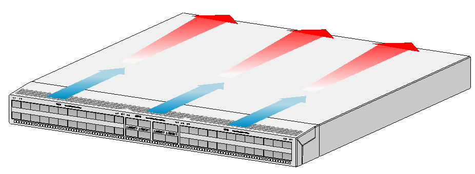
To dissipate heat timely and ensure system stability, the switch uses the front-rear air aisle cooling system. Consider the site ventilation design when you plan the installation site for the switch.
Table5-1 Cooling system for the switch
|
Switch model |
Available fan trays |
Airflow direction |
|
· S9826-32C · S6826-48Y8C |
LSWM1FANSA |
From the power supply side to the port side |
|
LSWM1FANSAB |
From the port side to the power supply side |
Figure5-1 Airflow from the power supply side to the port side through the S9826-32C chassis (with LSWM1FANSA fan trays)
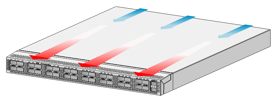
Figure5-2 Airflow from the port side to the power supply side through the S9826-32C chassis (with LSWM1FANSAB fan trays)
Figure5-3 Airflow from the power supply side to the port side through the S6826-48Y8C chassis (with LSWM1FANSA fan trays)
Figure5-4 Airflow from the port side to the power supply side through the S6826-48Y8C chassis (with LSWM1FANSAB fan trays)