- Table of Contents
- Related Documents
-
| Title | Size | Download |
|---|---|---|
| 01-Installation Guide | 4.60 MB |
Examining the installation site
Installing the switch in a 19-inch rack
Rack-mounting procedures at a glance
Mounting brackets, chassis rails, and grounding cable installation positions
Attaching the mounting brackets and chassis rails to the chassis
Connecting the grounding cable to the chassis
Attaching the slide rails to the rack
Mounting the switch in the rack
Installing and removing fan trays
Installing and removing power supplies
3 Accessing the switch for the first time
Setting up the configuration environment
Connecting the mini USB console cable
4 Maintenance and troubleshooting
Configuration terminal display problems
1 Preparing for installation
The H3C S6826 Switch Series and the H3C S9826 Switch Series include the following models:
|
Product series |
Product model |
Product code |
|
S6826 series |
S6826-48Y8C |
LS-6826-48Y8C |
|
S9826 series |
S9826-32C |
LS-9826-32C |
Safety recommendations
To avoid any equipment damage or bodily injury caused by incorrect use, read the following safety recommendations before installation. Note that the recommendations do not cover every possible hazardous condition.
· Before cleaning the switch, remove all power cords from the switch. Do not clean the switch with wet cloth or liquid.
· Do not place the switch near water or in a damp environment. Prevent water or moisture from entering the switch chassis.
· Do not place the switch on an unstable case or desk. The switch might be severely damaged in case of a fall.
· Ensure good ventilation of the equipment room and keep the air inlet and outlet vents of the switch free of obstruction.
· Connect the yellow-green protection grounding cable before power-on.
· Make sure the operating voltage is in the required range.
· To avoid electrical shocks, do not open the chassis while the switch is operating or when the switch is just powered off.
· When replacing field replaceable units (FRUs), including power supplies and fan trays, wear an ESD wrist strap to avoid damaging the units.
Examining the installation site
The switch must be used indoors.
Mount your switch in a rack and verify the following items:
· Adequate clearance is reserved at the air inlet and outlet vents for ventilation.
· The rack has a good ventilation system.
· Identify the hot aisle and cold aisle at the installation site, and make sure ambient air flows into the switch from the cold aisle and exhausts to the hot aisle.
· Identify the airflow designs of neighboring devices, and prevent hot air flowing out of the neighboring devices from entering the top device.
· The rack is sturdy enough to support the switch and its accessories.
· The rack is reliably grounded.
To ensure correct operation and long service life of your switch, install it in an environment that meets the requirements described in the following subsections.
Temperature/humidity
Maintain appropriate temperature and humidity in the equipment room.
· Lasting high relative humidity can cause poor insulation, electricity leakage, mechanical property change of materials, and metal corrosion.
· Lasting low relative humidity can cause washer contraction and ESD and cause problems including loose mounting screws and circuit failure.
· High temperature can accelerate the aging of insulation materials and significantly lower the reliability and lifespan of the switch.
For the temperature and humidity requirements for the switch, see S6826 & S9826 Switch Series Hardware Information and Specifications.
Cleanliness
Dust buildup on the chassis might result in electrostatic adsorption, which causes poor contact of metal components and contact points. In the worst case, this might shorten the device's lifetime and even cause communication failure. Table1-1 describes the dust concentration limits in the equipment room.
Table1-1 Dust concentration limit in the equipment room
|
Substance |
Particle diameter |
Concentration limit |
|
Dust particles |
≥ 0.5 µm |
≤ 3.5 × 10⁶ particles/m3 |
|
Dust particles |
≥ 5 µm |
≤ 3 × 10⁴ particles/m3 |
|
Dust (suspension) |
≤ 75 µm |
≤ 0.2 mg/m3 |
|
Dust (sedimentation) |
75 µm to 150 µm |
≤ 1.5 mg/(m2h) |
Corrosive gases can accelerate corrosion and aging of metal components. Make sure the corrosive gases in the equipment room do not exceed the concentration limits as shown in Table1-2.
Table1-2 Harmful gas limits in the equipment room
|
Gas |
Average concentration (mg/m3) |
Maximum concentration (mg/m3) |
|
SO2 |
0.3 |
1.0 |
|
H2S |
0.1 |
0.5 |
|
Cl2 |
0.1 |
0.3 |
|
HCI |
0.1 |
0.5 |
|
HF |
0.01 |
0.03 |
|
NH3 |
1.0 |
3.0 |
|
O3 |
0.05 |
0.1 |
|
NOX |
0.5 |
1.0 |
EMI
All electromagnetic interference (EMI) sources, from outside or inside of the switch and application system, adversely affect the switch in the following ways:
· A conduction pattern of capacitance coupling.
· Inductance coupling.
· Electromagnetic wave radiation.
· Common impedance (including the grounding system) coupling.
To prevent EMI, use the following guidelines:
· If AC power is used, use a single-phase three-wire power receptacle with protection earth (PE) to filter interference from the power grid.
· Keep the switch far away from radio transmitting stations, radar stations, and high-frequency devices.
· Use electromagnetic shielding, for example, shielded interface cables, when necessary.
· To prevent signal ports from getting damaged by overvoltage or overcurrent caused by lightning strikes, route interface cables only indoors.
Laser safety
|
|
WARNING! · The switch is a Class 1M laser device. · Disconnected optical fibers or transceiver modules might emit invisible laser light. Do not stare into beams or view directly with optical instruments when the switch is operating. |
Installation tools
No installation tools are provided with the switch. Prepare the following tools yourself:
· Phillips screwdriver.
· ESD wrist strap.
· Marker.
2 Installing the switch
|
|
CAUTION: Keep the tamper-proof seal on a mounting screw on the chassis cover intact, and if you want to open the chassis, contact H3C for permission. Otherwise, H3C shall not be liable for any consequence caused thereby. |
Figure2-1 Hardware installation flow
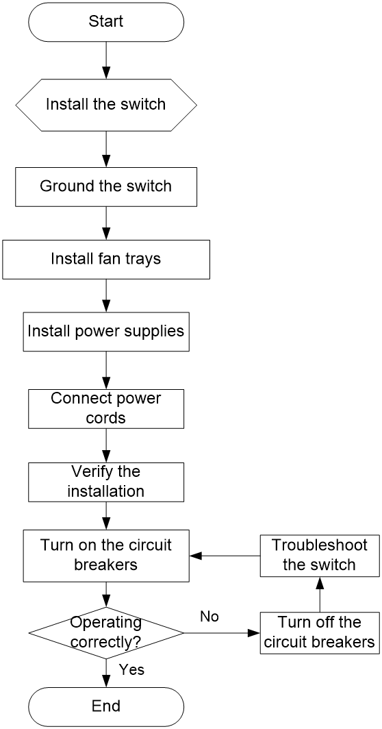
Installing the switch in a 19-inch rack
Rack-mounting procedures at a glance
Figure2-2 Rack-mounting procedure

|
|
NOTE: If a rack shelf is available, you can put the switch on the rack shelf, slide the switch to an appropriate location, and attach the switch to the rack with the mounting brackets. |
Follow these guidelines when you install the switch in a 19-inch rack:
· The distance between the front and rear posts of the rack must meet the requirements described in Table2-2.
· To secure the switch to the rack, you must install not only mounting brackets, but also chassis rails and slide rails.
Rack-mounting requirements
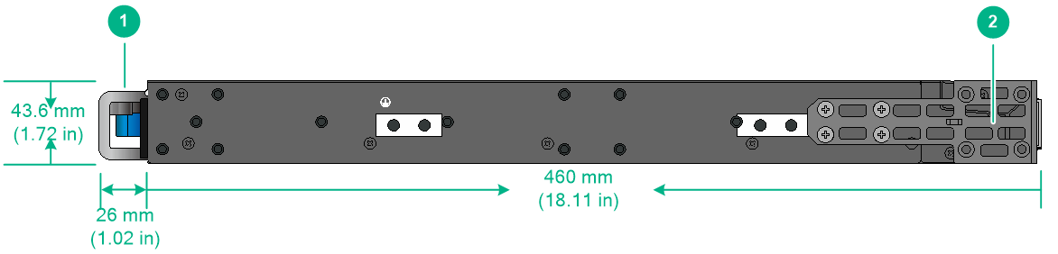
Figure2-3 S6826-48Y8C chassis dimensions (mounting brackets installed at the port side)
|
(1) Power supply handle |
(2) Mounting bracket |
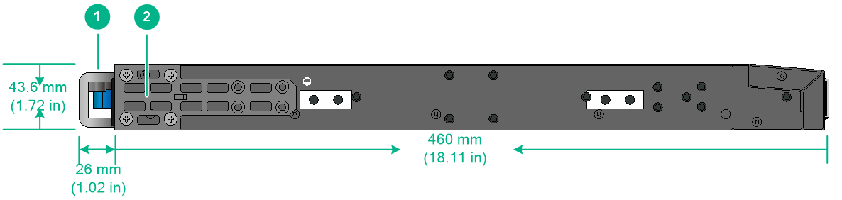
Figure2-4 S6826-48Y8C chassis dimensions (mounting brackets installed at the power supply side)
|
(1) Power supply handle |
(2) Mounting bracket |
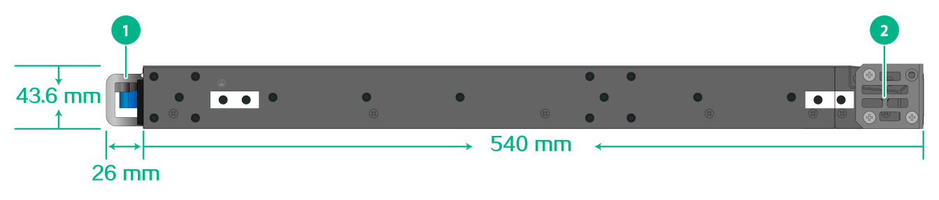
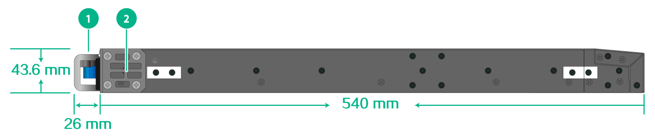
Figure2-5 S9826-32C chassis dimensions (mounting brackets installed at the port side)
|
(1) Power supply handle |
(2) Mounting bracket |
Figure2-6 S9826-32C chassis dimensions (mounting brackets installed at the power supply side)
|
(1) Power supply handle |
(2) Mounting bracket |
Table2-2 Distance requirements between the front and rear rack posts
|
Switch model |
Installation method |
Chassis dimensions |
Distance between the front and rear rack posts |
Rack requirements |
|
S6826-48Y8C |
Using the mounting brackets and long slide rails (provided) |
· Height—43.6 mm (1.72 in)/1 RU · Width—440 mm (17.32 in) · Depth—486 mm (19.13 in) ¡ 26 mm (1.02 in) for the power supply/fan tray handles ¡ 460 mm (18.11 in) for the chassis |
692 to 854 mm (27.24 to 33.62 in) |
· A minimum of 800 mm (31.50 in) in depth (recommended) · A minimum of 130 mm (5.12 in) between the front rack post and the front door. · A minimum of 550 mm (21.65 in) between the front rack post and the rear door. |
|
Using the mounting brackets and super-short slide rails (optional, with the chassis rails not reaching out of the chassis) |
401 to 565 mm (15.79 to 22.24 in) |
|||
|
Using the mounting brackets and super-short slide rails (optional, with chassis rails reaching out of the chassis) |
499 to 692 mm (19.65 to 27.24 in) |
|||
|
S9826-32C |
Using the mounting brackets and long slide rails (provided) |
· Height—43.6 mm (1.72 in)/1 RU · Width—440 mm (17.32 in) · Depth—566 mm (22.28 in) ¡ 26 mm (1.02 in) for the power supply/fan tray handles ¡ 540 mm (21.26 in) for the chassis |
621 to 934 mm (24.45 to 36.77 in) |
· A minimum of 800 mm (31.50 in) in depth (recommended) · A minimum of 130 mm (5.12 in) between the front rack post and the front door. · A minimum of 630 mm (24.80 in) between the front rack post and the rear door. |
|
Using the mounting brackets and short slide rails (optional) |
401 to 714 mm (15.79 to 28.11 in) |
Installation accessories
Table2-3 Installation accessories
|
Switch model |
Mounting brackets (provided) |
Cable management brackets |
Rack mounting rail kit |
|
S6826-48Y8C |
1U high, one pair. See Figure2-7. |
N/A |
· 1U high, including one pair of long slide rails and one pair of chassis rails (provided). See Figure2-9. · 1U high, including one pair of super-short slide rails and one pair of chassis rails (optional). See Figure2-11. |
|
S9826-32C |
1U high, one pair. See Figure2-8. |
N/A |
· 1U high, including one pair of long slide rails and one pair of chassis rails (provided). See Figure2-9. · 1U high, including one pair of short slide rails and one pair of chassis rails (optional). See Figure2-10. |
Figure2-7 Mounting brackets provided with the S6826-48Y8C switch
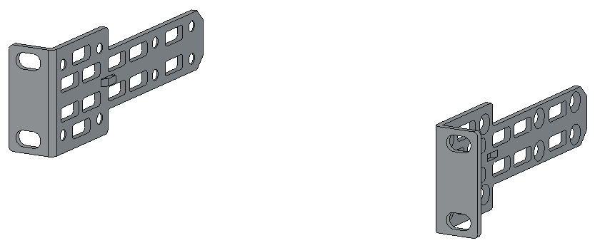
Figure2-8 Mounting brackets provided with the S9826-32C switch
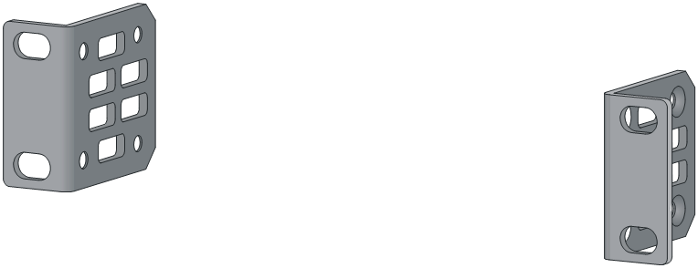
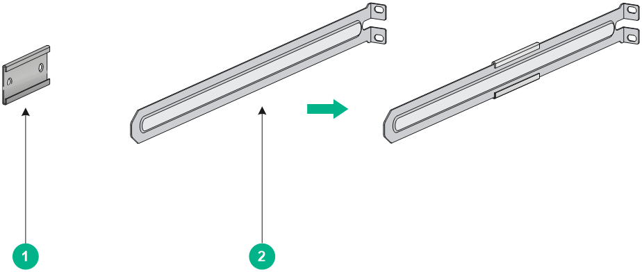
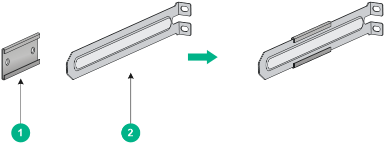
Figure2-9 1U long slide rail and chassis rail
|
(1) Chassis rail |
(2) Long slide rail |
Figure2-10 1U short slide rail and chassis rail
|
(1) Chassis rail |
(2) Short slide rail |
Figure2-11 1U super-short slide rail and chassis rail
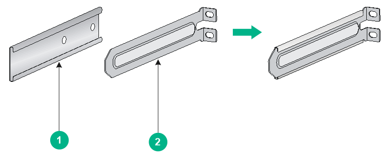
|
(1) Chassis rail |
(2) Super-short slide rail |
Mounting brackets, chassis rails, and grounding cable installation positions
The switch has one mounting position near the network ports and one mounting position near the power supplies for mounting brackets.
The switch provides two grounding points: primary grounding point (with a grounding sign) and auxiliary grounding point.. See Figure2-12 and Figure2-13.
Select installation positions for the mounting brackets, chassis rails, and grounding cable as required.
Figure2-12 Mounting brackets and grounding cable installation positions on the S6826-48Y8C switch
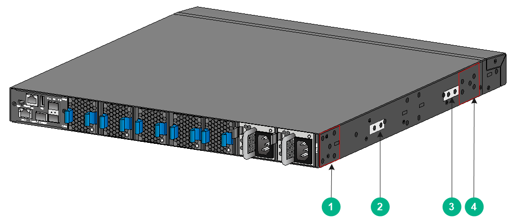
|
(1) Power supply-side mounting position |
(2) Primary grounding point |
|
(3) Auxiliary grounding point |
(4) Port-side mounting position |
Figure2-13 Mounting brackets and grounding cable installation positions on the S9826-32C switch
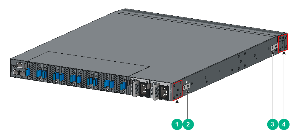
|
(1) Power supply-side mounting position |
(2) Primary grounding point |
|
(3) Auxiliary grounding point |
(4) Port-side mounting position |
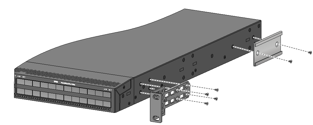
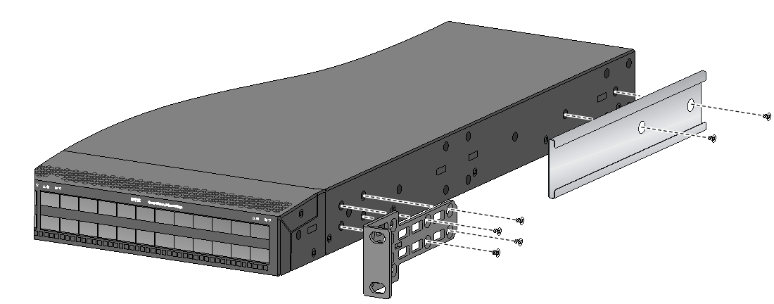
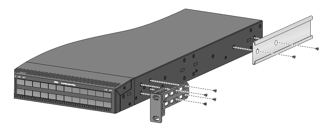
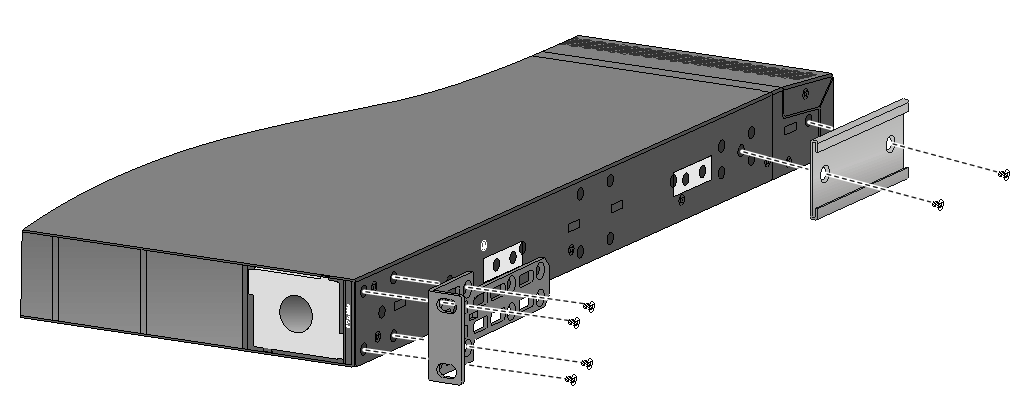
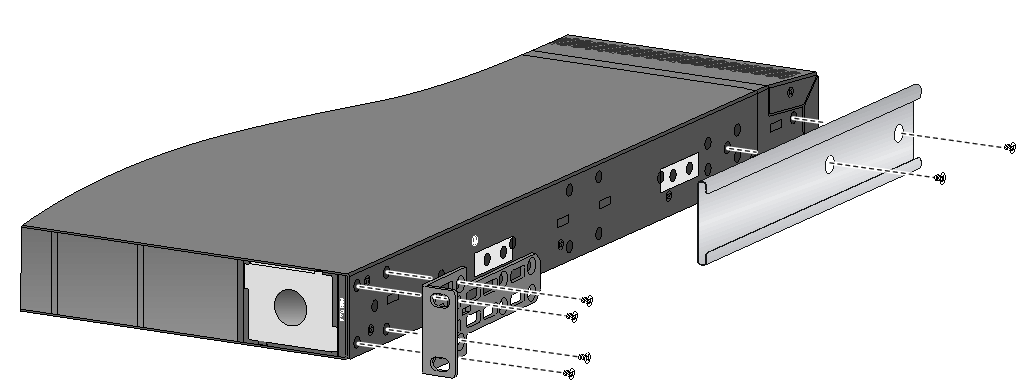
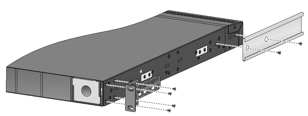
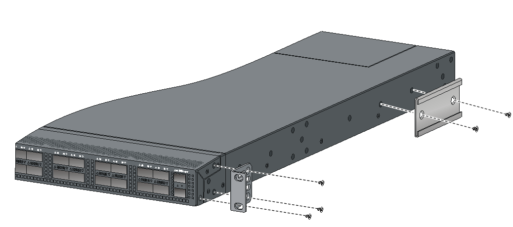
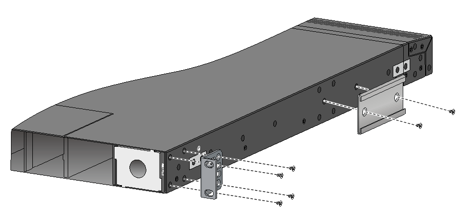
Attaching the mounting brackets and chassis rails to the chassis
1. Place the wide flange of the mounting bracket against the chassis side panel. Align the mounting bracket installation holes with the screw holes in the chassis. Use M4 screws (provided) to attach the mounting bracket to the chassis.
¡ To install the mounting brackets at the port-side mounting position, see Figure2-14, Figure2-15, Figure2-16, and Figure2-20.
¡ To install the mounting brackets at the power supply-side mounting position, see Figure2-17, Figure2-18, Figure2-19, and Figure2-21.
For the S6826-48Y8C switch, to install the mounting brackets at the power supply-side mounting position, use the four screw holes nearest to the power supply side. To install the mounting brackets at the network port-side mounting position, use the four screw holes nearest to the network port side.
2. Determine the chassis rail installation position:
¡ If the mounting brackets are installed at the power supply-side mounting position, install the chassis rails near the port side.
¡ If the mounting brackets are installed at the network port-side mounting position, install the chassis rails near the power supply side.
3. Place the chassis rail against the chassis side panel. Align the chassis rail installation holes with the screw holes. Use the provided M4 screws (recommended torque: 12 kgf-cm) to attach the chassis rail to the chassis. See Figure2-14 to Figure2-21.
You can use super-short slide rails and long chassis rails to rack-mount the S6826-48Y8C switch. Based on the rack depth, install the long chassis rails not reaching out of the chassis, as shown in Figure2-15 and Figure2-18 or reaching out of the chassis, as shown in Figure2-16 and Figure2-19.
|
|
NOTE: Secure the mounting brackets and chassis rails to both sides of the chassis in the same way. |
Connecting the grounding cable to the chassis
|
|
CAUTION: The primary grounding point and auxiliary grounding point are located on the left panel of the chassis. You must connect the grounding cable to the grounding point before you mount the switch in the rack. |
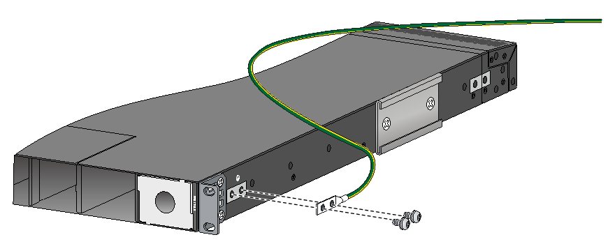
This section uses the primary grounding point on the S9826-32C switch as an example.
To connect the grounding cable to a grounding point:
1. Choose a grounding point as required.
This example uses the primary grounding point.
2. Unpack the grounding cable and grounding screws.
3. Use two grounding screws to attach the two-hole grounding lug of the grounding cable to the grounding holes at the grounding point. Use a screwdriver to tighten the screws (recommended torque: 20 kgf-cm). See Figure2-22.
Figure2-22 Attaching the grounding cable to the primary grounding point on the S9826-32C switch
Attaching the slide rails to the rack
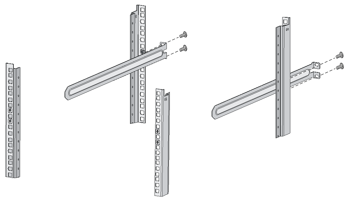
1. Identify the slide rail installation position in the rack.
2. Install cage nuts (user-supplied) in the mounting holes in the rack posts.
3. Align the screw holes in one slide rail with the cage nuts in a rear rack post, and use user-supplied M6 screws to attach the slide rail to the post (recommended torque: 30 kgf-cm). See Figure2-23.
4. Repeat the preceding steps to attach the other slide rail to the other rear rack post.
Keep the two slide rails at the same height so the slide rails can attach into the chassis rails.
Figure2-23 Installing the slide rails
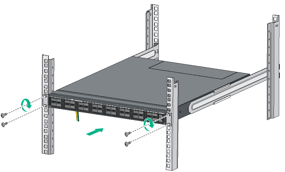
Mounting the switch in the rack
This task requires two people.
To mount the switch in the rack:
1. Wear an ESD wrist strap and make sure it makes good skin contact and is reliably grounded.
2. Verify that the mounting brackets and chassis rails have been securely attached to the switch chassis.
3. Verify that the slide rails have been correctly attached to the rear rack posts.
4. Attach cage nuts (user-supplied) to the front rack posts and make sure they are at the same level as the slide rails.
5. One person performs the following operations:
a. Supporting the bottom of the switch, aligns the chassis rails with the slide rails on the rack posts.
b. Pushes the switch slowly to slide the chassis rails along the slide rails until the mounting brackets are flush with the rack posts.
6. Another person uses user-supplied M6 screws (recommended torque: 30 kgf-cm) to attach the mounting brackets to the rack.
To secure the switch in the rack, make sure the front ends of the slide rails reach out of the chassis rails.
The rack-mounting procedures are the same for the S6826-48Y8C and S9826-32C switches. The following figures use the S9826-32C switch as an example.
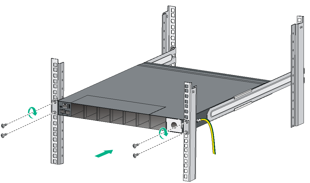
Figure2-25 Mounting the S9826-32C switch in the rack (Port-side mounting position for the mounting brackets)
Grounding the switch
|
|
CAUTION: · Correctly connecting the grounding cable is crucial to lightning protection and EMI protection. · Do not connect the grounding cable to a fire main or lightning rod. · To guarantee the grounding effect and avoid switch damage, use the grounding cable provided with the switch to connect the switch to a grounding strip in the equipment room. |
The power input end of the switch has a noise filter, whose central ground is directly connected to the chassis to form the chassis ground (commonly known as PGND). You must securely connect this chassis ground to the earth so the faradism and leakage electricity can be safely released to the earth to minimize EMI susceptibility of the switch.
To ground the switch:
1. As shown in Figure2-26, attach the two-hole grounding lug of the grounding cable to a grounding point on the chassis. For more information, see "Connecting the grounding cable to the chassis."
The grounding point in Figure2-26 is for illustration only.
2. Remove the hex nut of a grounding post on the grounding strip.
3. Attach the ring terminal of the grounding cable to the grounding post on the grounding strip, and secure the ring terminal to the grounding post with the hex nut.
Figure2-26 Connecting the grounding cable to a grounding strip
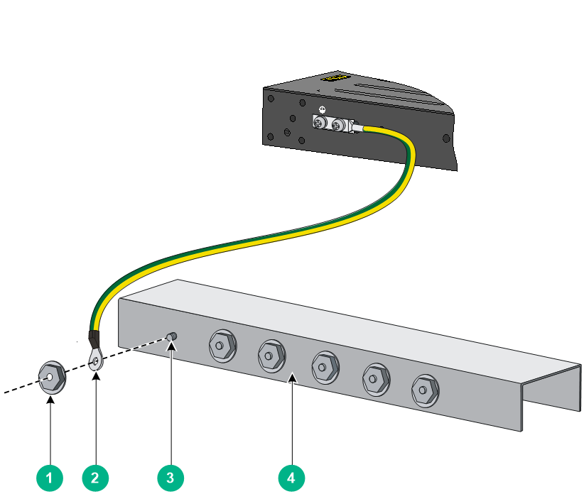
|
(1) Hex nut |
(2) Ring terminal |
|
(3) Grounding post |
(4) Grounding strip |
Installing and removing fan trays
|
|
CAUTION: The switch has multiple fan tray slots. To ensure good ventilation of the switch, follow these guidelines to install and remove fan trays: · The switch is provided with the fan tray slots empty. Before powering on the switch, make sure all fan tray slots have fan trays installed and the fan trays are the same model. · Make sure all slots have a module or filler panel installed when the switch is operating. · If multiple fan trays fail on an operating switch, do not remove the fan trays at the same time. Replace the fan trays one after another and finish replacing a fan tray within 3 minutes. |
The installation and removal procedures are the same for the LSWM1FANSA and LSWM1FANSAB,fan trays. The following installation and removal procedures use the LSWM1FANSA fan tray as an example.
Installing a fan tray
|
|
CAUTION: To prevent damage to the fan tray or the connectors on the backplane, insert the fan tray gently. If you encounter a hard resistance while inserting the fan tray, pull out the fan tray and insert it again. |
|
|
IMPORTANT: Before powering on the switch, make sure the fan tray airflow direction and the preferred airflow direction of the switch are the same. If they are not the same, the system generates traps and logs. You can use the fan prefer-direction command to configure the preferred airflow direction for the switch. By default, the preferred airflow direction of the switch is from the port side to the power supply side. For more information about the fan prefer-direction command, see H3C S6826 & S9826 Switch Series Fundamentals Command Reference. |
Select fan trays for the switch as needed. For the available fan trays and their specifications, see S6826 & S9826 Switch Series Hardware Information and Specifications.
To install a fan tray:
1. Wear an ESD wrist strap and make sure it makes good skin contact and is reliably grounded.
2. Unpack the fan tray and verify that the fan tray model is correct.
3. Orient the fan tray with the "TOP" mark on top. Grasp the handle of the fan tray with one hand and support the fan tray bottom with the other, and slide the fan tray along the guide rails into the slot until the fan tray is fully seated in the slot and has a firm contact with the backplane. See Figure2-27.
Figure2-27 Installing an LSWM1FANSA fan tray in the S9826-32C switch

Removing a fan tray
|
|
WARNING! · Ensure electricity safety and never touch the rotating fans when you hot-swap a fan tray. · To prevent a fan from causing loud noise, do not touch the fan blades and rotation axis, even if the fan is not rotating. |
To remove a fan tray:
1. Wear an ESD wrist strap and make sure it makes good skin contact and is reliably grounded.
2. Grasp the handle of the fan tray with one hand and pull the fan tray part way out of the slot. Support the fan tray bottom with the other and pull the fan tray completely out of the slot.
3. Put the removed fan tray in an antistatic bag.
Figure2-28 Removing an LSWM1FANSA fan tray
Installing and removing power supplies
|
|
WARNING! · To avoid bodily injury and device damage, strictly follow the procedures in Figure2-29 and Figure2-30 to install and remove a power supply. · Provide a separate circuit breaker for each power supply. |
The S6826-48Y8C and S9826-32C switches each have two power supply slots and come with power supply slot PWR1 empty and PWR2 installed with a filler panel. You can install power supplies for the switch as required.
For information about the available power supplies, see S6826 & S9826 Switch Series Hardware Information and Specifications.
Figure2-29 Installation procedure
![]()
![]()
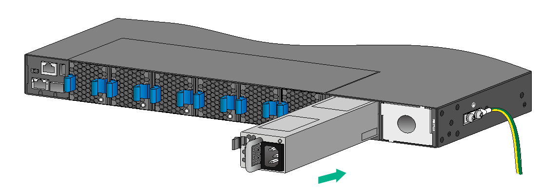
Installing a power supply
|
CAUTION: · Follow the forward inertia of the power supply when inserting it into the chassis, and make sure the power supply has firm contact with the connectors on the backplane. · To prevent damage to the connectors inside the switch chassis, insert the power supply gently. If you encounter a hard resistance while inserting the power supply, pull out the power supply and insert it again. |
The LSVM1AC650 and LSVM1DC650 installation procedure is the same on the S6826 switch series and S9826 switch series. The figures in this section use the S9826-32C switch as an example.
To install a power supply:
1. Wear an ESD wrist strap and make sure it makes good skin contact and is reliably grounded.
2. Remove the filler panel, if any, from the target power supply slot, as shown in Figure2-31.
Figure2-31 Removing a filler panel
3. Unpack the power supply and verify that the power supply model is correct.
4. Correctly orient the power supply with the words on the power supply upward. Grasp the handle of the power supply with one hand and support its bottom with the other, and slide the power supply slowly along the guide rails into the slot.
The slot is foolproof. If you cannot insert the power supply into the slot, re-orient the power supply rather than use excessive force to push it in.
Figure2-32 Installing a power supply (LSVM1AC650)
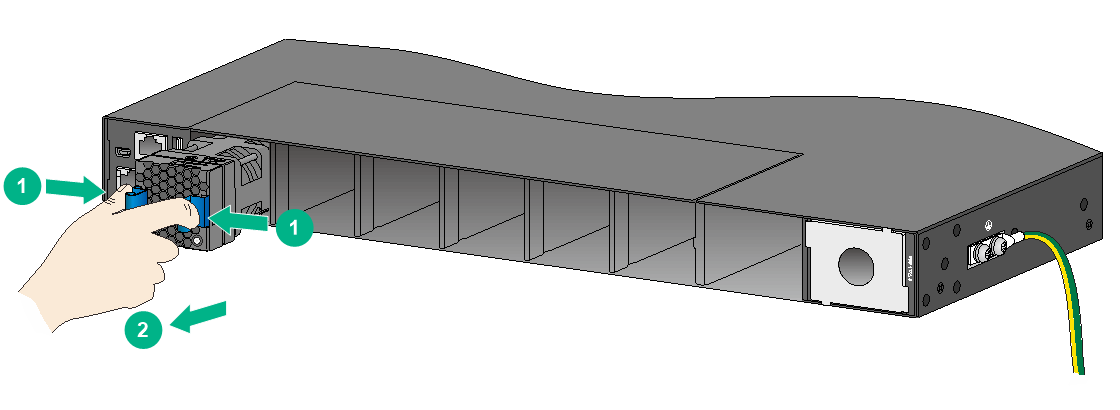
Removing a power supply
|
|
CAUTION: When an S6826-48Y8C or S9826-32C switch has two power supplies in 1+1 redundancy mode, removing one power supply does not affect the operation of the switch. When the switch has only one power supply installed, removing the power supply powers off the switch. |
The LSVM1AC650 and LSVM1DC650 removal procedure is the same on the S6826 switch series and S9826 switch series. The figures in this section use the S9826-32C switch as an example.
To remove a power supply:
1. Wear an ESD wrist strap and make sure it makes good skin contact and is reliably grounded.
2. Squeeze the tabs on the power cord connector with your thumb and forefinger, and pull the connector out to remove the power cord, as shown in Figure2-33.
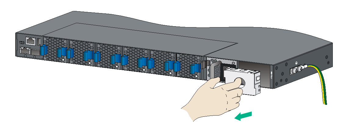
3. Hold the handle on the power supply with one hand, pivot the latch on the power supply to the right with your thumb, and pull the power supply part way out of the slot, as shown in Figure2-34.
4. Supporting the power supply bottom with one hand, slowly pull the power supply out with the other hand.
5. Put the removed power supply in an antistatic bag for future use.
6. If you are not to install a new power supply, install a filler panel in the slot to ensure good ventilation in the switch.
Figure2-33 Removing the DC power cord
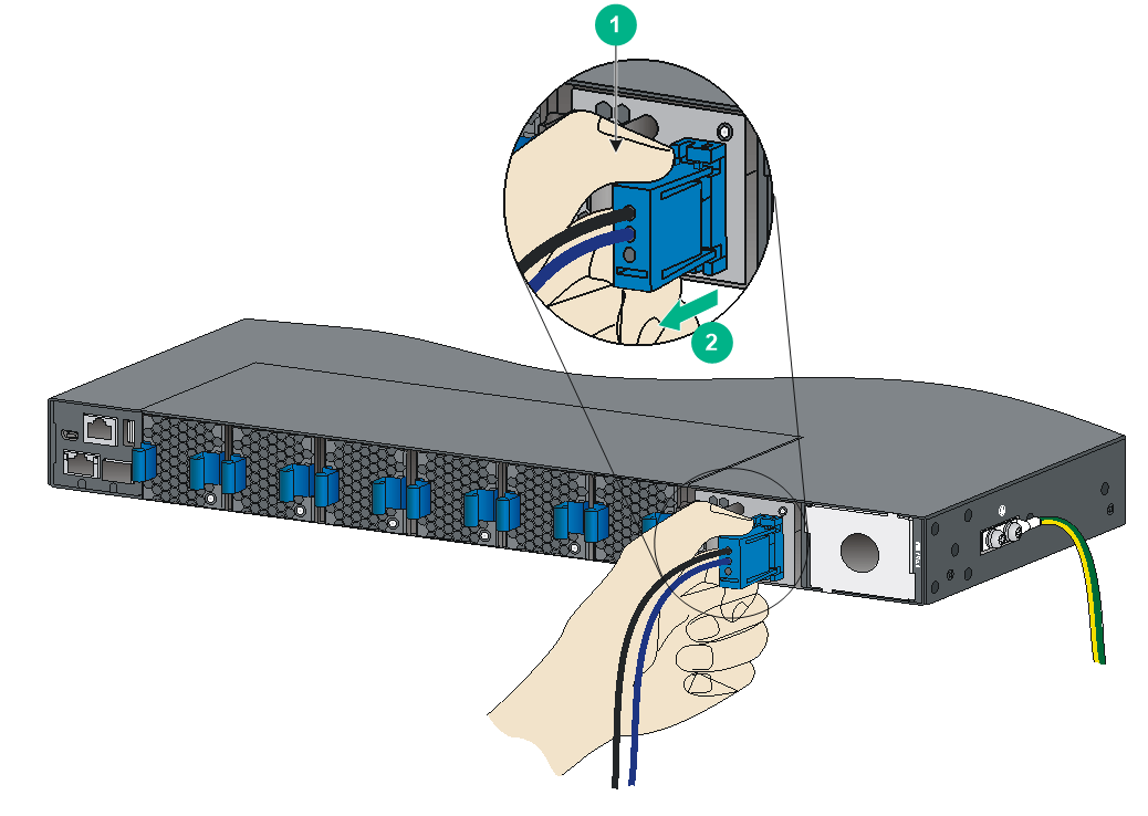
|
(1) Press the tabs on the power cord connector with your thumb and forefinger |
|
(2) Pull the power cord connector out |
Figure2-34 Removing the power supply
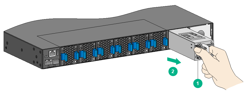
|
(1) Pivot the latch to the right with your thumb |
(2) Pull the power supply out |
Connecting the power cords
|
|
WARNING! Provide a circuit breaker for each power input. When you connect a power cord, make sure the circuit breaker is switched off. |
Connecting an AC power cord
1. Insert the female connector of the AC power cord supplied with the power supply into the power receptacle on the power supply.
2. Use a cable tie to secure the power cord to the handle of the power supply, as shown in Figure2-35.
3. Connect the other end of the power cord to an AC power outlet.
Figure2-35 Connecting an AC power cord to the LSVM1AC650 power supply
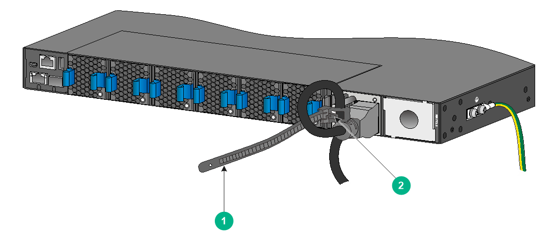
|
(1) Cable tie |
|
(2) Tighten the cable tie to secure the power cord to the handle of the power supply |
Connecting a DC power cord
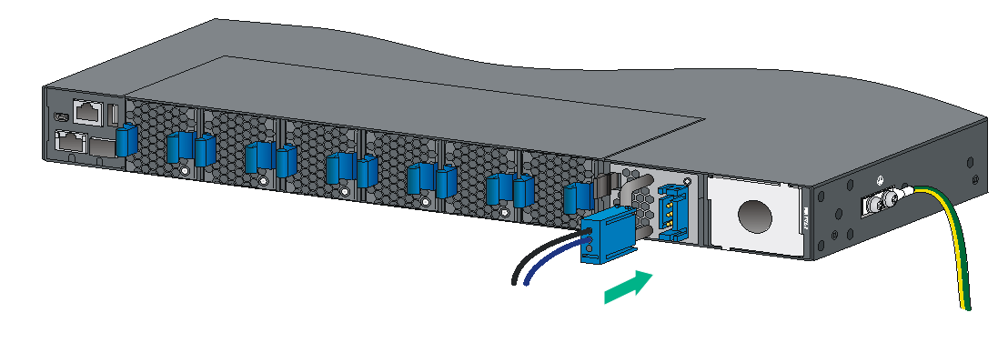
1. Align the power cord plug with the power receptacle on the power supply, and insert the plug into the receptacle (see Figure2-36).
The plug and receptacle are foolproof. If you cannot insert the plug into the receptacle, re-orient the plug rather than use excessive force to push it in.
2. Use a cable tie to secure the power cord to the handle of the power supply, as shown in Figure2-35.
3. Connect the other end of the power cord to the DC power source.
Figure2-36 Connecting a DC power cord to the LSVM1DC650 power supply
If the provided DC power cord cannot meet your connection requirements, use the following table to prepare a suitable copper cable as the DC power cord.
Table2-4 Requirements for a suitable DC power cord
|
Power supply model |
Power cord connector |
Minimum cross sectional area of the conductor |
Cross sectional area of the provided power cord |
Maximum cross sectional area of the conductor |
|
LSVM1DC650 |
Use the connector of the provided power cord |
3.3 mm2 or 12 AWG |
3.3 mm2 or 12 AWG |
5.3 mm2 or 10 AWG |
Verifying the installation
After you complete the installation, verify that:
· There is enough space for heat dissipation around the switch, and the rack is stable.
· The grounding cable is securely connected.
· The correct power source is used.
· The power cords are correctly connected.
· All the interface cables are cabled indoors. If any cable is routed outdoors, verify that the socket strip with lightning protection and lightning arresters for network ports have been correctly connected.
3 Accessing the switch for the first time
Setting up the configuration environment
You can access the switch through the serial console port or the mini USB console port. As a best practice, use the serial console port to access the switch. To access the switch through the mini USB console port, you need to prepare a mini USB console cable yourself.
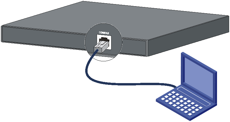
The example uses a console cable to connect a console terminal (PC) to the serial console port on the switch.
Figure3-1 Connecting the serial console port to a terminal
Connecting the console cable
A serial console cable is an 8-core cable, with a crimped RJ-45 connector at one end for connecting to the serial console port of the switch, and a DB-9 female connector at the other end for connecting to the serial port on the console terminal.
Figure3-2 Serial console cable
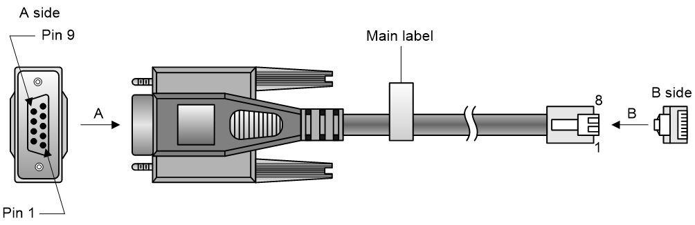
Table3-1 Console port signaling and pinout
|
RJ-45 |
Signal |
DB-9 |
Signal |
|
1 |
RTS |
8 |
CTS |
|
2 |
DTR |
6 |
DSR |
|
3 |
TXD |
2 |
RXD |
|
4 |
SG |
5 |
SG |
|
5 |
SG |
5 |
SG |
|
6 |
RXD |
3 |
TXD |
|
7 |
DSR |
4 |
DTR |
|
8 |
CTS |
7 |
RTS |
To connect a terminal (for example, a PC) to the switch by using the serial console cable:
1. Plug the DB-9 female connector of the serial console cable to the serial port of the PC.
2. Connect the RJ-45 connector to the serial console port of the switch.
|
|
NOTE: · Identify the mark on the console port and make sure you are connecting to the correct port. · The serial ports on PCs do not support hot swapping. To connect a PC to an operating switch, first connect the PC end. To disconnect a PC from an operating switch, first disconnect the switch end. |
Connecting the mini USB console cable
A mini USB console cable has a USB mini-Type B connector at one end to connect to the mini USB console port of the switch, and a standard USB Type A connector at the other end to connect to the USB port on the configuration terminal.
To connect to the configuration terminal through the USB mini console cable:
1. Connect the standard USB Type A connector to the USB port of the configuration terminal.
2. Connect the USB mini Type B connector to the Mini USB console port of the switch.
3. Click the following link, or copy it to the address bar on the browser to log in to download page of the USB console driver, and download the driver.
4. Select a driver program according to the operating system you use:
¡ XR21V1410_XR21B1411_Windows_Ver1840_x86_Installer.EXE—32-bit operating system.
¡ XR21V1410_XR21B1411_Windows_Ver1840_x64_Installer.EXE—64-bit operating system.
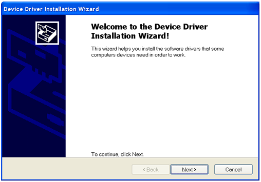
5. Click Next on the installation wizard.
Figure3-3 Device Driver Installation Wizard
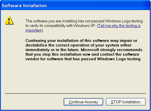
6. Click Continue Anyway if the following dialog box appears.
Figure3-4 Software Installation
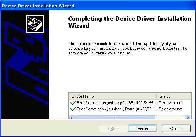
7. Click Finish.
Figure3-5 Completing the device driver installation wizard
Setting terminal parameters
To configure and manage the switch through the console port, you must run a terminal emulator program, TeraTermPro or PuTTY, on your configuration terminal. You can use the emulator program to connect a network device, a Telnet site, or an SSH site. For more information about the terminal emulator programs, see the user guides for these programs
The following are the required terminal settings:
· Bits per second—9600.
· Data bits—8.
· Stop bits—1.
· Parity—None.
· Flow control—None.
Powering on the switch
1. Before powering on the switch, verify that the following conditions are met:
¡ All the fan tray slots have a fan tray installed.
¡ The power cords are connected correctly.
¡ The input power voltage is as required by the switch.
¡ The console cable is connected correctly.
¡ The configuration terminal (a PC, for example) has started, and its serial port settings are consistent with the console port settings on the switch.
2. Power on the switch.
During the startup process, you can access BootWare menus to perform tasks such as software upgrade and file management. The BootWare interface and menu options vary by software version. For more information about BootWare menu options, see the software-matching release notes for the device.
3. After the startup completes, you can access the CLI to configure the switch.
For more information about the configuration commands and CLI, see H3C S6826 & S9826 Switch Series Command References.
4 Maintenance and troubleshooting
Power supply failure
Symptom
The power supply status LED on a power supply is not steady green (active state) or flashing green (standby state)
For more information about the LEDs on a power supply, see H3C LSVM1AC650 & LSVM1DC650 Power Supplies User Manual.
Solution
To resolve the issue:
1. Verify that the power cord is connected correctly.
2. Verify that the power source is as required by the switch.
3. Verify that the operating temperature of the switch is in the acceptable range and the power supply has good ventilation.
4. If the issue persists, contact H3C Support.
To replace a power supply, see "Installing and removing power supplies."
Fan tray failure
|
|
CAUTION: The S6826-48Y8C switch has five fan tray slots. The S9826-32C switch has six fan tray slots. To replace failed fan trays on an operating switch, do not remove the fan trays at the same time if multiple fan trays fail on an operating switch. Replace the fan trays one after another and finish replacing a fan tray within 3 minutes. |
Symptom
The status LED on an LSWM1FANSA or LSWM1FANSAB fan tray is steady orange and the system outputs alarm messages.
Solution
See "Installing and removing fan trays" to replace the fan tray. If the issue persists, contact H3C Support.
Configuration terminal display problems
No display
Symptom
The configuration terminal displays nothing when the switch is powered on.
Solution
To resolve the issue:
1. Verify that the power system is operating correctly.
2. Verify that the console cable is connected correctly.
3. Verify that the console cable does not have any problems and the terminal settings are correct.
4. If the issue persists, contact H3C Support.
Garbled display
Symptom
The configuration terminal has a garbled display.
Solution
To resolve the issue:
1. Verify that the following settings are configured for the terminal:
¡ Baud rate—9,600.
¡ Data bits—8.
¡ Parity—None.
¡ Stop bits—1.
¡ Flow control—None.
2. If the issue persists, contact H3C Support.