- Table of Contents
- Related Documents
-
| Title | Size | Download |
|---|---|---|
| 01-Text | 24.48 MB |
Contents
General safety recommendations
Examining the installation site
Rack or workbench requirements
Installing the device in a standard 19-inch rack
Device dimensions and rack requirements
Installing the device by using the mounting brackets and slide rails
Installing the device by using the mounting brackets and a rack shelf
Installing the device on a workbench
Grounding the device installed on a workbench
Grounding the device installed in a rack
4 Installing internal removable components
Installing a storage controller
5 Installing external removable components
Installing MIC-X interface cards
Connecting a high voltage DC power cord
Connecting copper Ethernet cables
Connecting E1 interface cables
9 Accessing the device for the first time
Connecting the device to a configuration terminal
Replacing a MIC-X interface card
Replacing a storage controller
11 Hardware management and maintenance
Displaying software and hardware version information for the device
Displaying device operating information
Displaying detailed device information
Displaying electrical label information for the device
Displaying CPU usage information
Displaying memory usage information
Displaying the fan tray operating status
Displaying the power supply operating status
Displaying device temperature information
Displaying transceiver module information
Diagnosing transceiver modules
Saving the running configuration
Rebooting the device or a module
Restrictions and guidelines for using RAID
Configuration terminal display issue
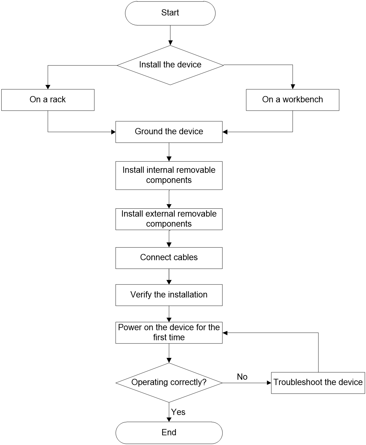
1 Device installation flow
The installation flows for SR6602-I and SR6602-IE gateways are as describe in Figure1-1.
Figure1-1 Device installation flow
2 Preparing for installation
Safety recommendations
To avoid any equipment damage or bodily injury, read the following safety recommendations before installation. Note that the recommendations do not cover every possible hazardous condition.
General safety recommendations
· Do not place the device on an unstable case or desk. The device might be severely damaged in case of a fall.
· Keep the chassis clean and dust-free.
· Do not place the device on a moist area, and avoid liquid flowing into the device. Do not use wet cloth to wipe the device.
· Handle the devices according to the sizes of and packaging symbols on the packages.
Electrical safety
· Clear the work area of possible electricity hazards, such as ungrounded power extension cables, missing safety grounds, and wet floors.
· Locate the emergency power-off switch in the room before installation so you can quickly shut power off when an electrical accident occurs.
· Make sure the operating voltage is in the required range.
· Before powering on the device, make sure the device is reliably grounded.
Laser safety
|
|
WARNING! Disconnected optical fibers or transceiver modules might emit invisible laser light. Do not stare into beams or view directly with optical instruments when the device is operating. |
The device is a Class 1 laser device.
To avoid ESD damage, use dust caps on disconnected optical fiber connectors. Insert a dust plug into each fiber port and each transceiver module port not in use.
Moving safety
When you move the device, follow these guidelines:
· To avoid damage, move and unpack the device with care.
· After you move the device from a location below 0°C (32°F) to the equipment room, follow these guidelines to prevent condensation:
¡ Wait a minimum of 30 minutes before unpacking the device.
¡ Wait a minimum of 2 hours before powering on the device.
· Before you move the device, remove all cables.
· If the device is to be transported over a long distance, perform the following tasks before the transport:
¡ Remove all removable components, such as power supplies and interface cards, and place them separately in antistatic bags.
¡ Replace the filler panels provided with the device to prevent obstacle intrusions and damages to the device.
· To transport the device over a short distance, make sure the removable components are securely installed on the device and the screws are tightly fastened.
· When you move or lift the chassis, support the bottom of the chassis, rather than hold any removable component.
ESD prevention
|
|
CAUTION: Make sure the resistance reading between human body and the ground is in the range of 1 to 10 megohms (Mohms). |
No ESD wrist strap is provided with the device. Purchase one yourself.
Always wear an ESD wrist strap when installing removable components. Make sure the wrist strap is reliably grounded.
To attach the ESD wrist strap:
1. Wear the wrist strap on your wrist.
2. Lock the wrist strap tight around your wrist to keep good contact with the skin.
3. Secure the wrist strap lock and the alligator clip lock together.
4. Attach the alligator clip to the rack or the workbench.
Examining the installation site
The device can only be used indoors. To ensure correct operation and a long lifespan for your device, the installation site must meet the following requirements.
Temperature and humidity
Maintain appropriate temperature and humidity in the equipment room at levels as described in Table2-1.
· Lasting high relative humidity can cause poor insulation, electricity leakage, mechanical property change of materials, and metal corrosion.
· Lasting low relative humidity can cause washer contraction and ESD and bring problems including loose captive screws and circuit failure.
· High temperature can accelerate the aging of insulation materials and significantly lower the reliability and lifespan of the device.
Table2-1 Temperature and humidity requirements
|
Item |
Specification |
|
Temperature |
· Operating: ¡ Without hard disks: 0°C to 45°C (32°F to 113°F) ¡ With hard disks: 0°C to 40°C (32°F to 104°F) ¡ Without GPUs: 0°C to 45°C (32°F to 113°F) ¡ With GPUs: 0°C to 40°C (32°F to 104°F) · Storage: –40°C to +70°C (–40°F to +158°F) |
|
Humidity |
· Operating: 5% RH to 95% RH, noncondensing · Storage: 5% RH to 95% RH, noncondensing |
Cleanliness
Dust buildup on the chassis might result in electrostatic adsorption, which causes poor contact of metal components and contact points, especially when indoor relative humidity is low. In the worst case, electrostatic adsorption can cause communication failure.
Table2-2 Dust concentration limit in the equipment room
|
Substance |
Concentration limit (particles/m3) |
|
Dust particles |
≤ 3 × 10⁴ (No visible dust on desk in three days) |
|
NOTE: Dust particle diameter ≥ 5 µm |
|
The equipment room must also meet strict limits on salts, acids, and sulfides to eliminate corrosion and premature aging of components, as shown in Table2-3.
Table2-3 Harmful gas limits in an equipment room
|
Gas |
Max. (mg/m3) |
|
SO2 |
0.2 |
|
H2S |
0.006 |
|
NH3 |
0.05 |
|
Cl2 |
0.01 |
|
NO2 |
0.04 |
Cooling system
For adequate cooling of the device, make sure the following requirements are met:
· A minimum clearance of 100 mm (3.94 in) is reserved around the inlet and outlet air vents.
· The installation site has a good cooling system.
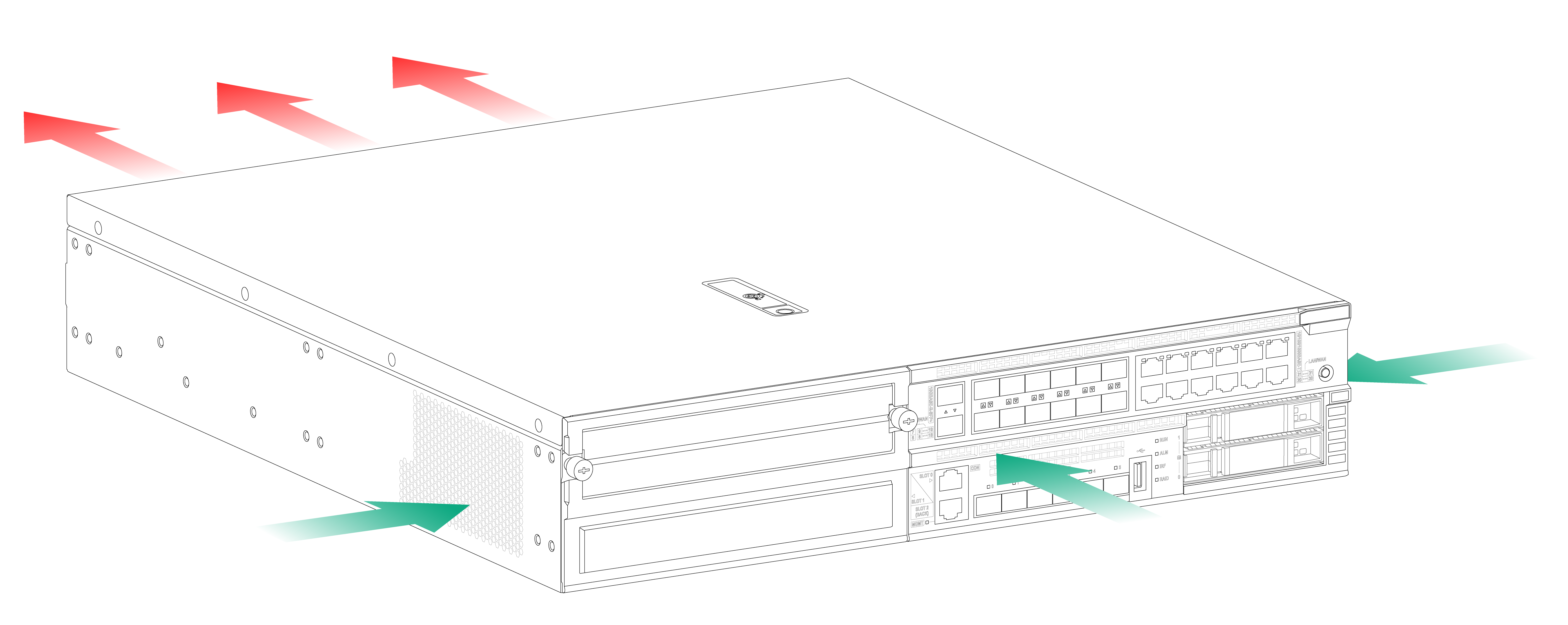
· Plan the cooling system at the installation site based on the airflow direction of the device.
· Verify the airflow directions of the devices above and below the device. Make sure the exhausted hot air of the lower device will not enter the upper device.
Figure2-1 Airflow through the chassis
Rack or workbench requirements
· Make sure the rack or workbench is sturdy enough to support the total weight of the device and its accessories. For more information about the device weight, see H3C SR6602-I[IE] AI Series ICT Converged Gateways Hardware Information and Specifications.
· Make sure the dimensions of the rack or workbench meet the requirements.
· Make sure the rack or workbench is reliably grounded.
EMI
All electromagnetic interference (EMI) sources, from outside or inside of the device and application system, adversely affect the device in the following ways:
· A conduction pattern of capacitance coupling.
· Inductance coupling.
· Electromagnetic wave radiation.
· Common impedance (including the grounding system) coupling.
To prevent EMI, use the following guidelines:
· If AC power is used, use a single-phase three-wire power receptacle with protection earth (PE) to filter interference from the power grid.
· Keep the device far away from radio transmitting stations, radar stations, and high-frequency devices.
· Use electromagnetic shielding, for example, shielded interface cables, when necessary.
Lightning protection
To protect the device from lightning better, do as follows:
· Make sure the installation site, power supply system, and the device are reliably grounded.
· Install a lightning arrester at the input end of the power supply to enhance the lightning protection capability of the power supply.
· To prevent signal ports from getting damaged by overvoltage or overcurrent caused by lightning strikes, route interface cables only indoors. If part of the network cable of an Ethernet port must be routed outdoors, connect a lightning arrester to the cable before you plug the cable into the port.
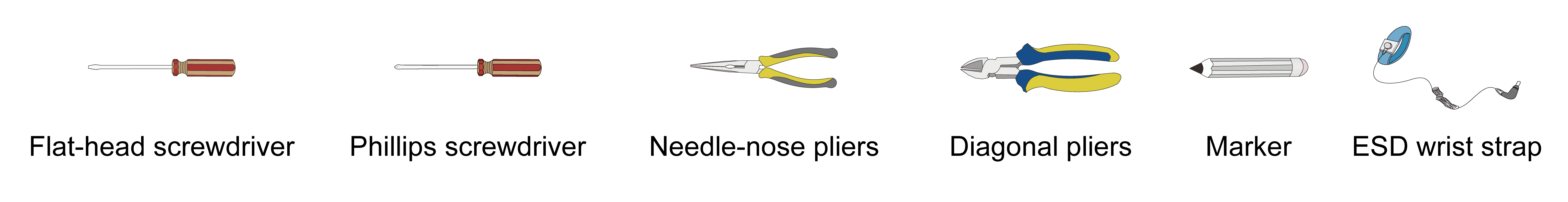
Installation tools
No installation tools are provided with the device. Prepare installation tools yourself as required.
The screwdrivers of different specifications are required to install the device. Prepare flat-head screwdrivers with a tip width of 2.5 mm (0.10 in), 5 mm (0.20 in), and 6 mm (0.24 in). Prepare Phillips screwdrivers with a tip width of 2.5 mm (0.10 in) and 6 mm (0.24 in).
Figure2-2 Installation tools
3 Installing the device
Installing the device in a standard 19-inch rack
|
|
WARNING! To avoid bodily injury and device damage, a minimum of two persons are required to install the device. |
|
CAUTION: Ensure a clearance of 1 RU (44.45 mm, or 1.75 in) between the device and walls or other devices for heat dissipation. |
Device dimensions and rack requirements
To mount the device in a rack, make sure the rack meets the requirements described in Table3-1.
Table3-1 Device dimensions and rack requirements
|
Device dimensions |
Rack requirements |
|
· Height—88 mm (3.46 in) · Width—440 mm (17.32 in) · Total depth—561 mm (20.09 in) ¡ 480 mm (18.90 in) for the chassis ¡ 56 mm (2.20 in) for the cable management bracket at the chassis front ¡ 25 mm (0.98 in) for the power supply handle at the chassis rear |
· A minimum of 0.6 m (1.97 ft) in depth (recommended). · A minimum of 70 mm (2.76 in) between the front rack posts and the front door. · A minimum of 50 mm (1.97 in) between the front rack posts to the rear door. · 384 mm (15.12 in) to 591 mm (23.27 in) from the front rack posts to the rear rack posts. |
Installation methods
Table3-2 Installation methods
|
Installation methods |
Required installation accessories |
|
Installing the device by using the mounting brackets and slide rails |
· Mounting brackets · Slide rails and chassis rails · M4 mounting bracket screws · M6 rack screws (user supplied) · Cage nuts (user supplied) |
|
Installing the device by using the mounting brackets and a rack shelf |
· Mounting brackets · M4 mounting bracket screws · M6 rack screws (user supplied) · Cage nuts (user supplied) · Rack shelf (user supplied) |
Installing the device by using the mounting brackets and slide rails
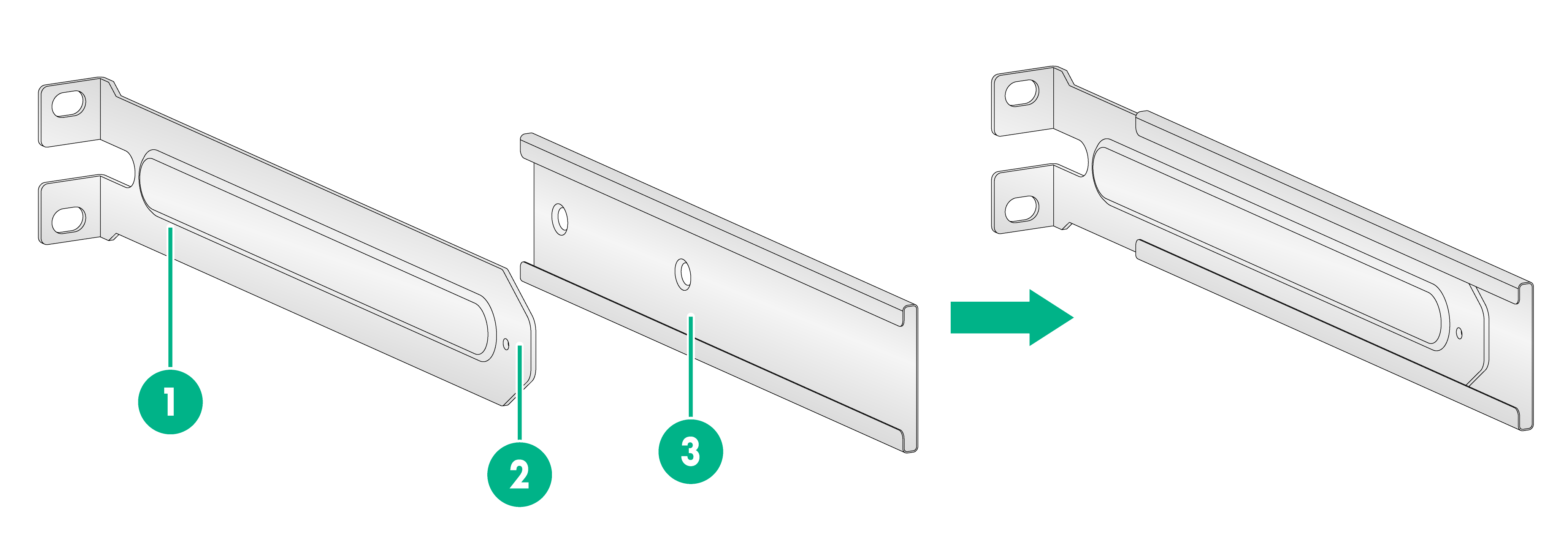
Figure3-1 Mounting brackets
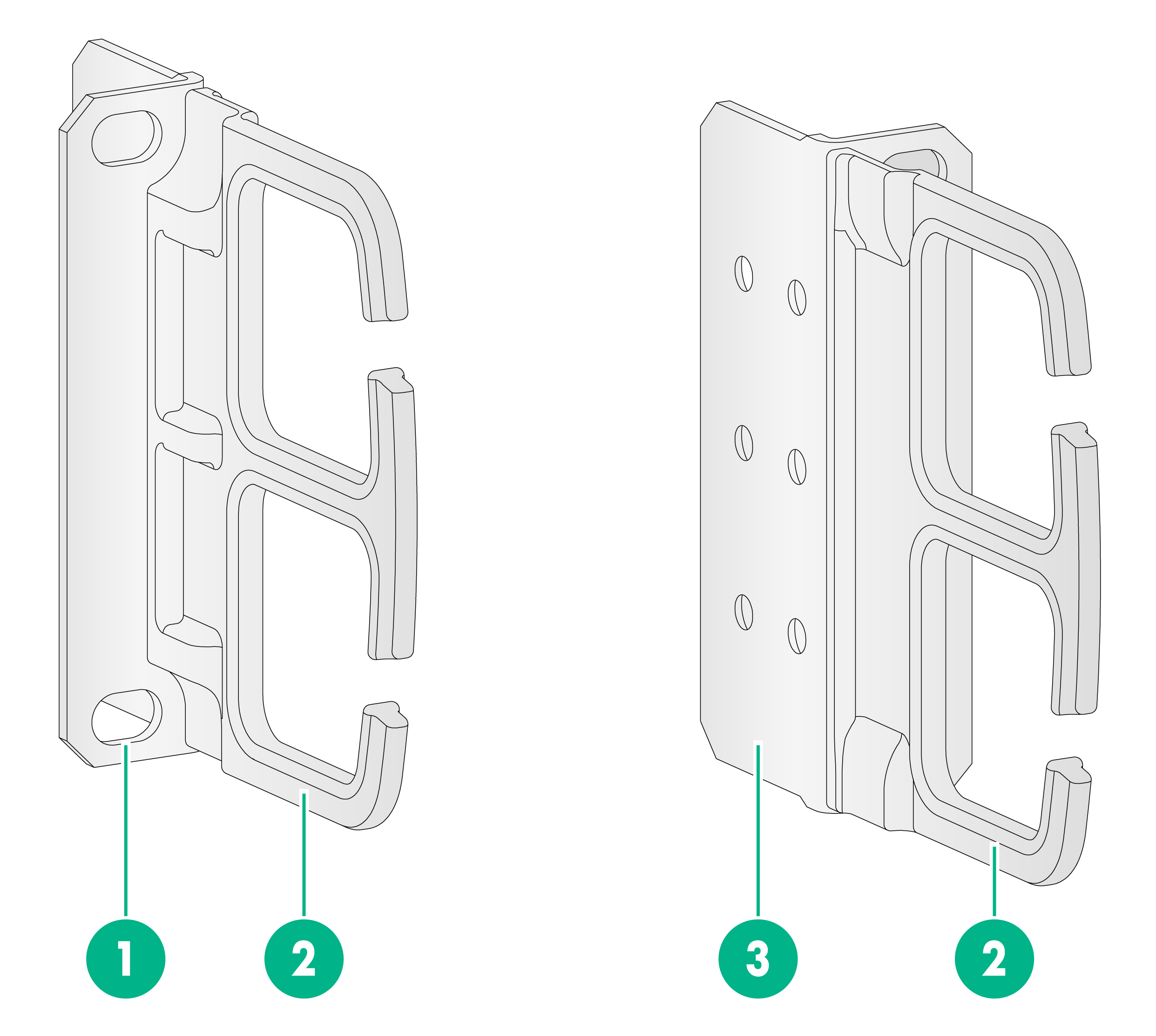
|
(1) M6 screw installation position |
(2) Cable management bracket |
|
(3) Mounting bracket |
|
Figure3-2 Slide rail and chassis rail
|
(1) Rear end of the slide rail |
(2) Front end of the slide rail |
|
(3) Chassis rail |
|
To install the device by using the mounting brackets and slide rails:
1. Wear an ESD wrist strap and make sure the strap makes good skin contact and is reliably grounded.
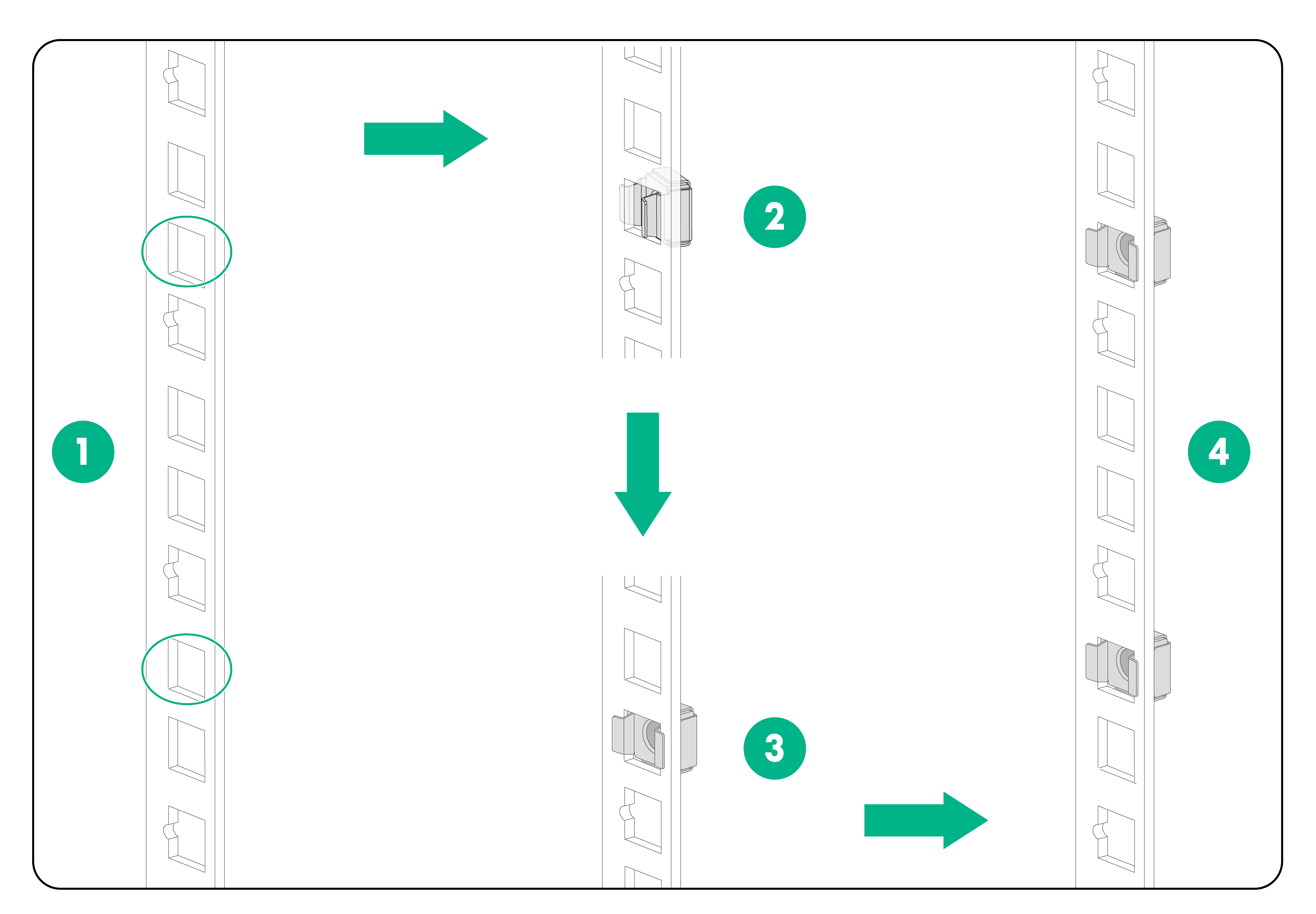
2. Use a mounting bracket to mark the cage nut installation positions on the front rack posts. Install cage nuts at the marked positions.
Figure3-3 Attaching cage nuts to the rack
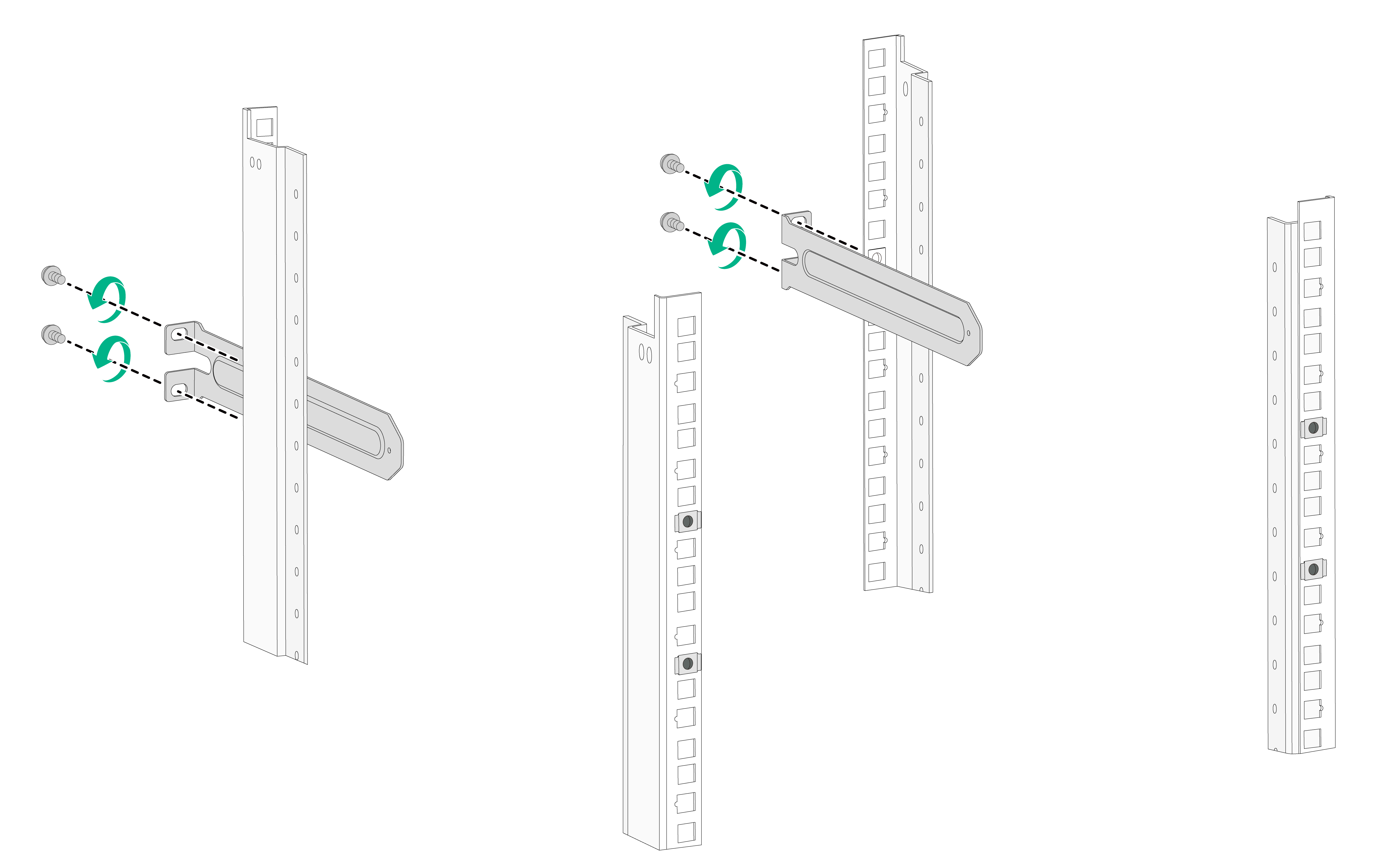
3. Use a slide rail to mark the cage nut installation positions on the rear rack posts. Install cage nuts at the marked positions and attach slide rails to the rack.
Figure3-4 Attaching slide rails to the rack
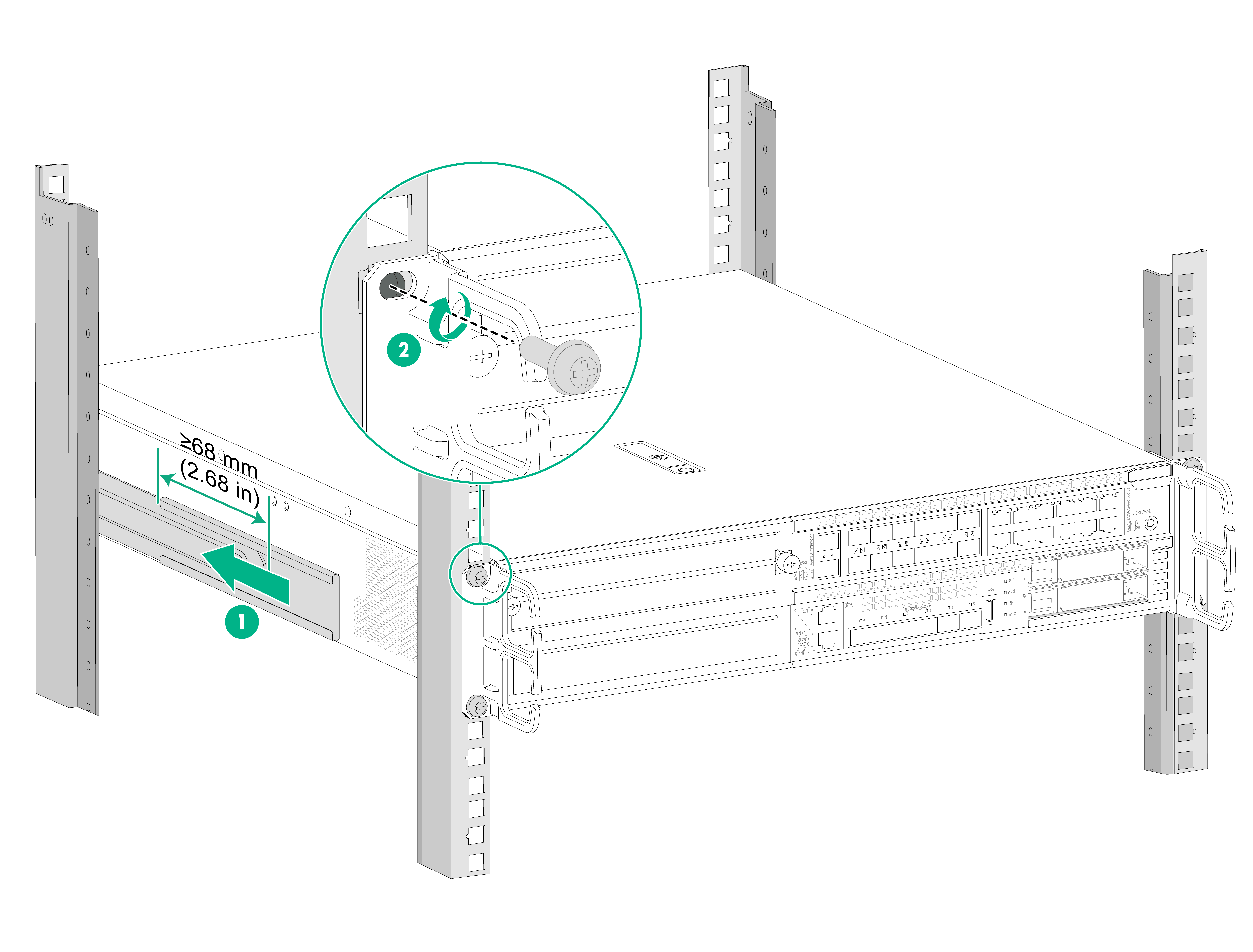
4. Use M4 mounting bracket screws to attach the chassis rails and mounting brackets to both sides of the device.
The device provides multiple chassis rail installation positions on its side panels. Attach the chassis rails to the correct positions based on the rack depth. For security purposes, make sure the front end of each slide rail slides a minimum length of 68 mm (2.68 in) into the chassis rail.
Figure3-5 Attaching the chassis rails and mounting brackets to the device
5. One person supports the bottom of the device, aligns the chassis rails with the slide rails, and slides the slide rails into the chassis rails until the mounting brackets are flush against the front rack posts.
6. Use the M6 rack screws to secure the mounting brackets to the front rack posts.
Figure3-6 Securing the device to the rack
Installing the device by using the mounting brackets and a rack shelf
|
|
IMPORTANT: Mounting brackets are not used for load bearing but for securing the device to the rack. To use a rack shelf for load bearing, make sure a rack shelf that can bear the weight of the device and its accessories is installed in the rack before rack-mounting the device. |
To install the device by using the mounting brackets and a rack shelf:
1. Wear an ESD wrist strap and make sure the strap makes good skin contact and is reliably grounded.
2. Identify the device installation position and secure the rack shelf to the rack.
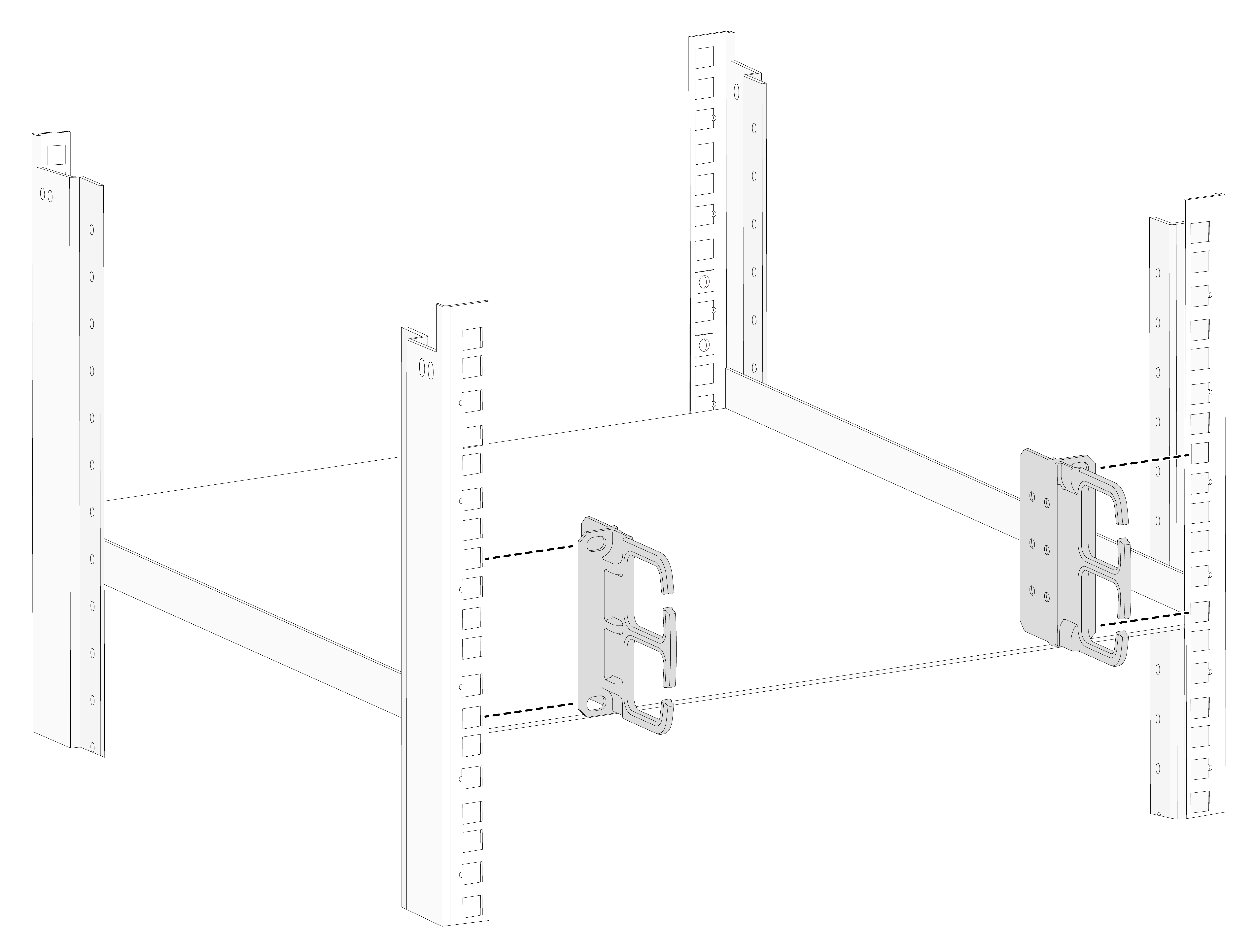
3. Use the mounting brackets to mark the cage nut installation positions on the front rack posts according to the rack shelf position.
Figure3-7 Marking the cage nut installation positions
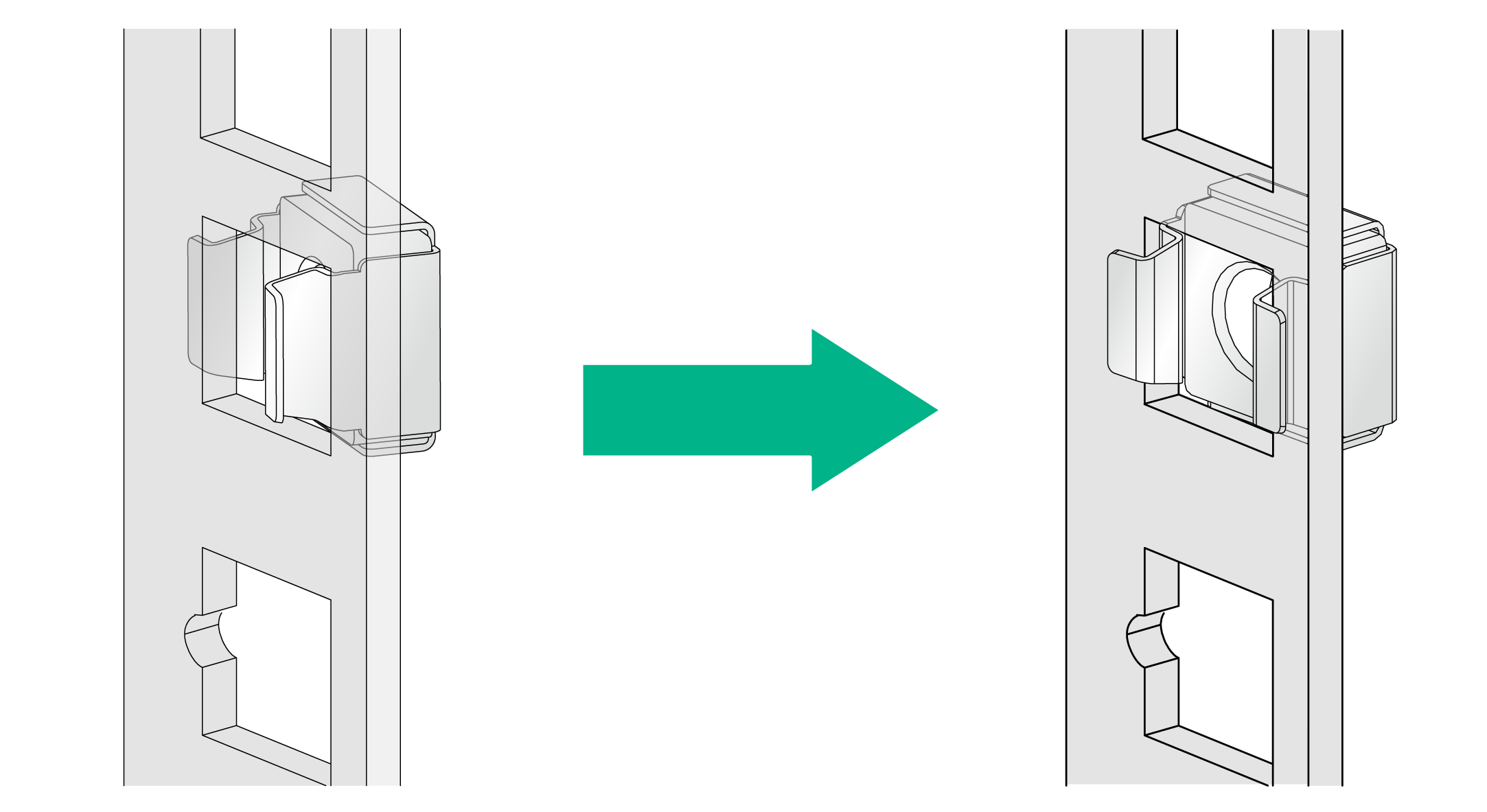
4. Install cage nuts at the marked positions.
Figure3-8 Installing cage nuts
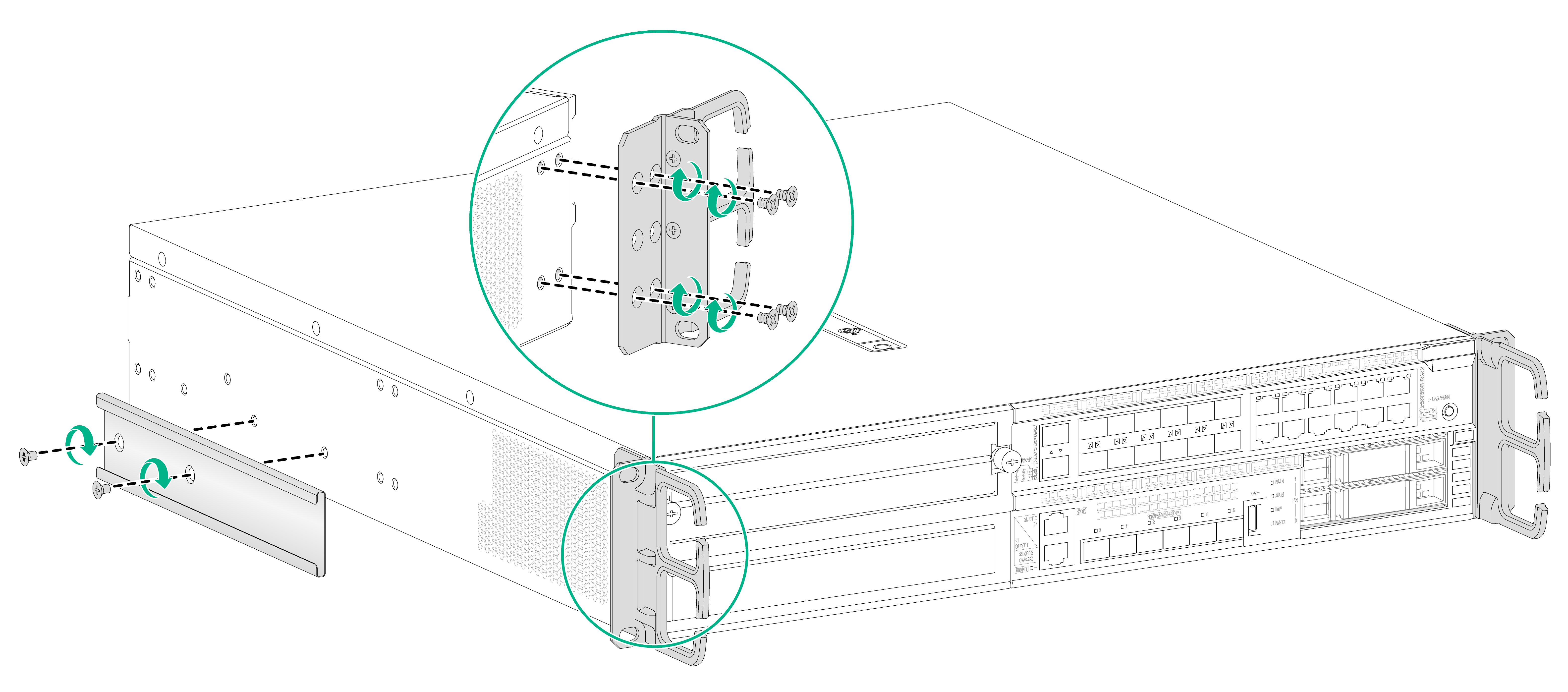
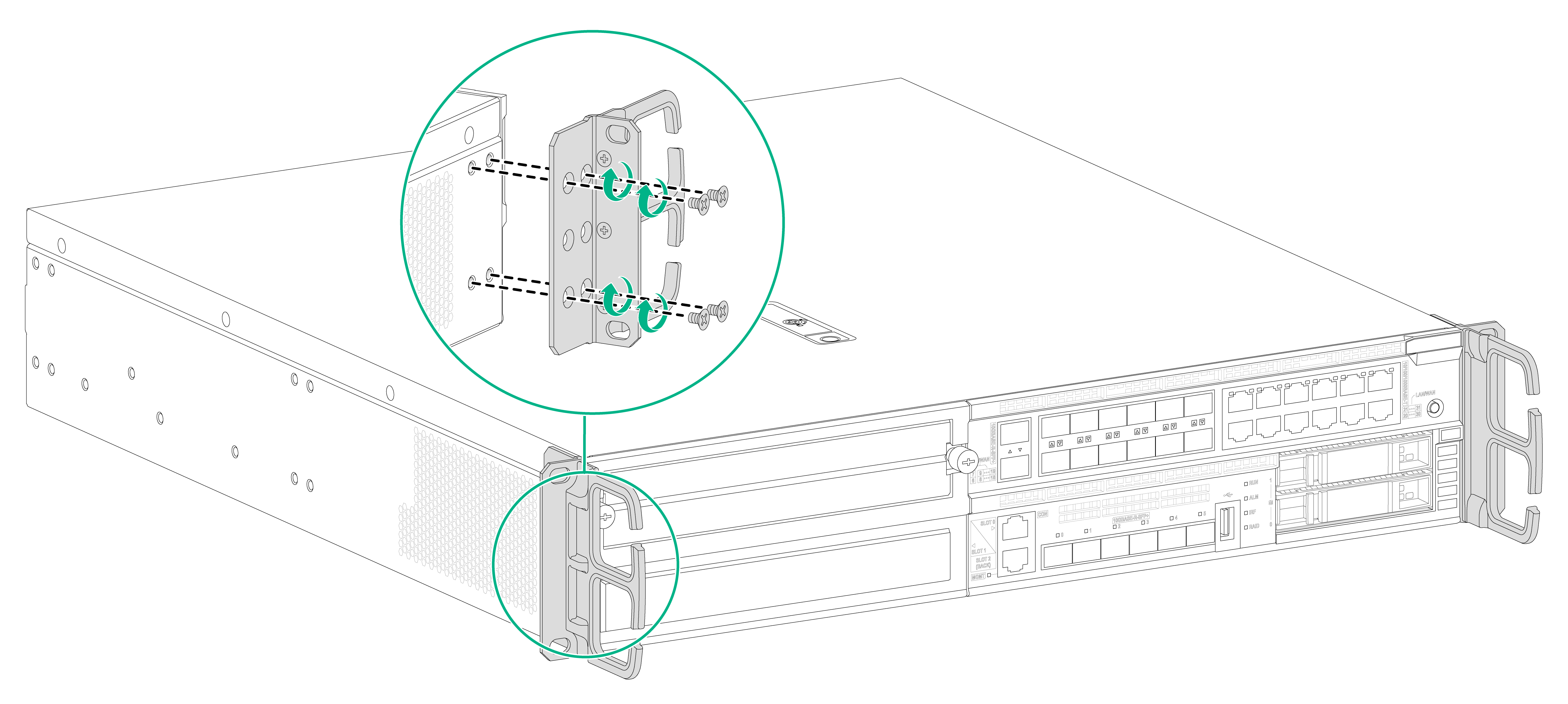
5. Use M4 mounting bracket screws to attach the mounting brackets to both sides of the device front panel.
Figure3-9 Attaching the mounting brackets to the device
6. Place the device horizontally on the rack shelf. Move the device along the rack shelf until the mounting brackets of the device are flush against the front the rack posts.
7. Use the M6 rack screws to secure the mounting brackets to the front rack posts.
Figure3-10 Securing the device to the rack
Installing the device on a workbench
|
|
CAUTION: · Make sure the workbench is stable and reliably grounded. · Reserve a minimum clearance of 100 mm (3.94 in) around the chassis for heat dissipation. · Do not place heavy objects on the device. |
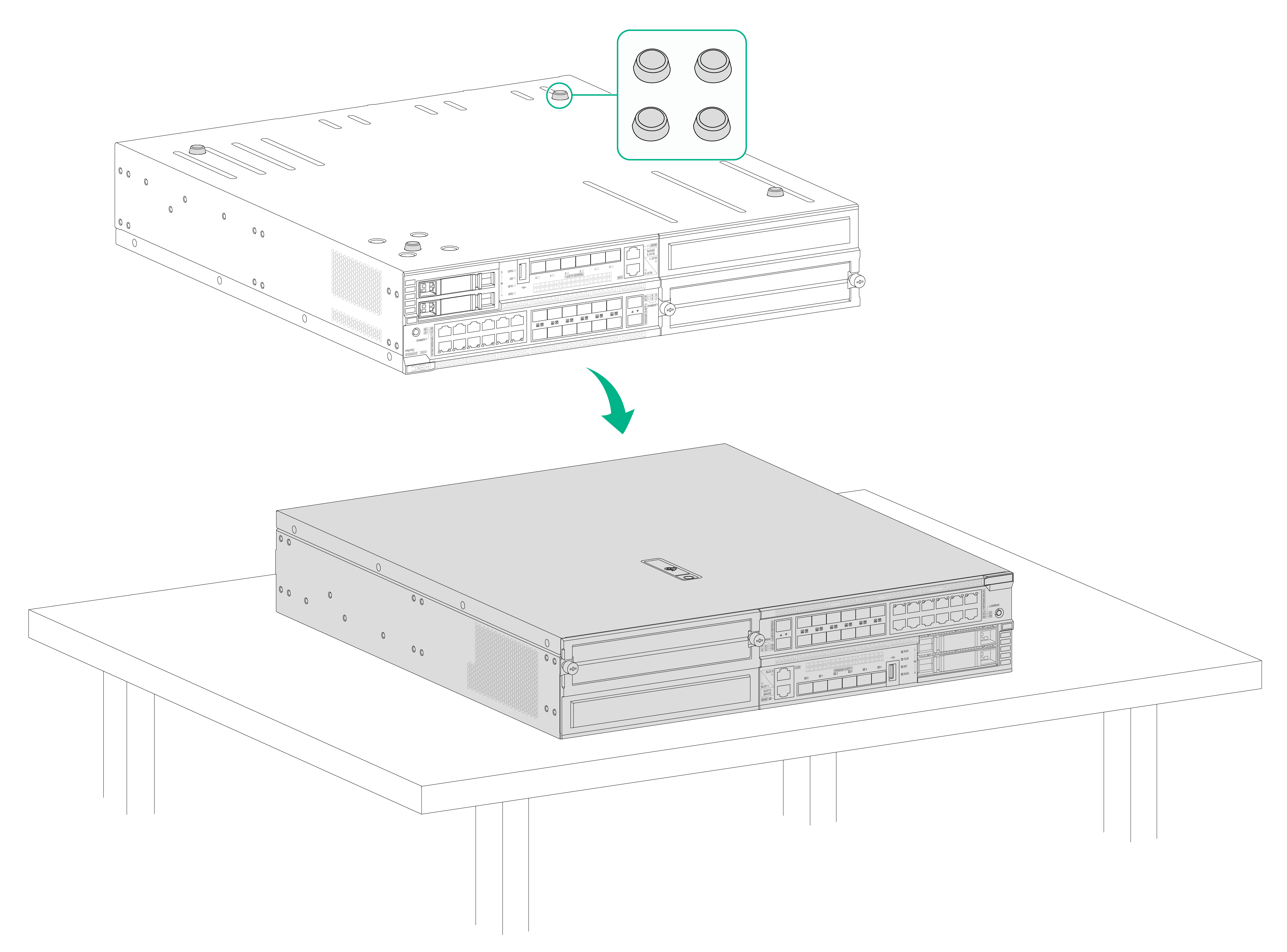
To install the device on a workbench:
1. Place the device upside down on the workbench and clean the four round holes in the chassis bottom with a dry cloth.
2. Attach the four rubber feet to the round holes in the chassis bottom.
3. Place the device with upside up on the workbench.
Figure3-11 Installing the device on a workbench
Grounding the device
|
|
WARNING! · Correctly connecting the grounding cable is crucial to lightning protection and EMI protection. · Do not connect the device grounding cable to a fire main or lightning rod. |
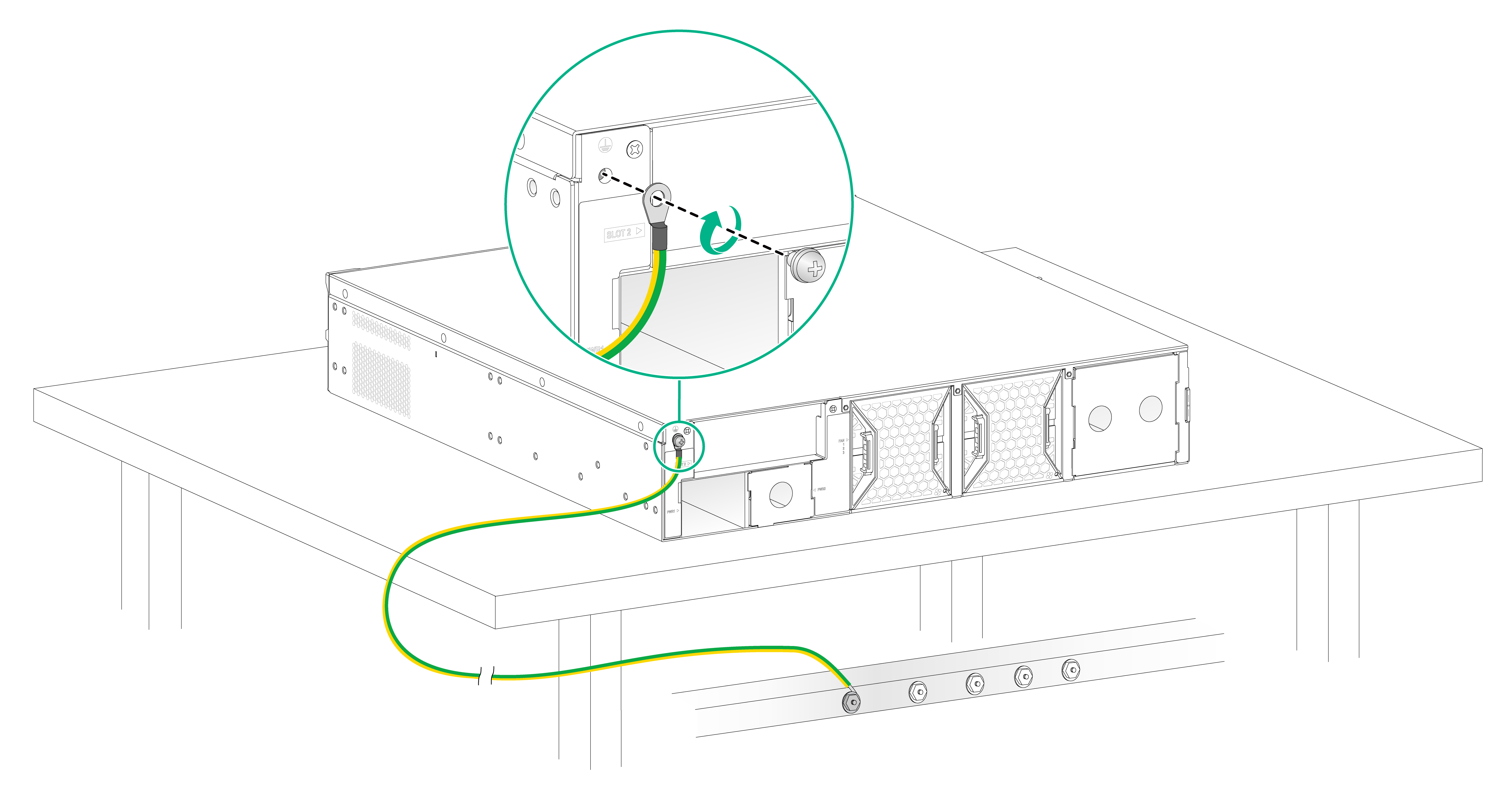
Grounding the device installed on a workbench
If a grounding strip is available at the installation site, you can connect the grounding cable of the device to the grounding strip.
To ground the device installed on a workbench by using a grounding strip:
1. Use a Phillips screwdriver to remove the grounding screw from the device chassis.
2. Attach the grounding screw to the ring terminal of the grounding cable.
3. Use a Phillips screwdriver to fasten the grounding screw into the grounding hole on the device.
4. Remove the hex nut from a grounding terminal on the grounding strip.
5. Use the needle-nose pliers to bend a hook at the other end of the grounding cable. Attach the hook to the grounding post, and secure the hook with the nut.
Figure3-12 Grounding the device mounted on a workbench
Grounding the device installed in a rack
If the device is installed in a rack, you can connect the grounding cable of the device to a grounding terminal on the rack.
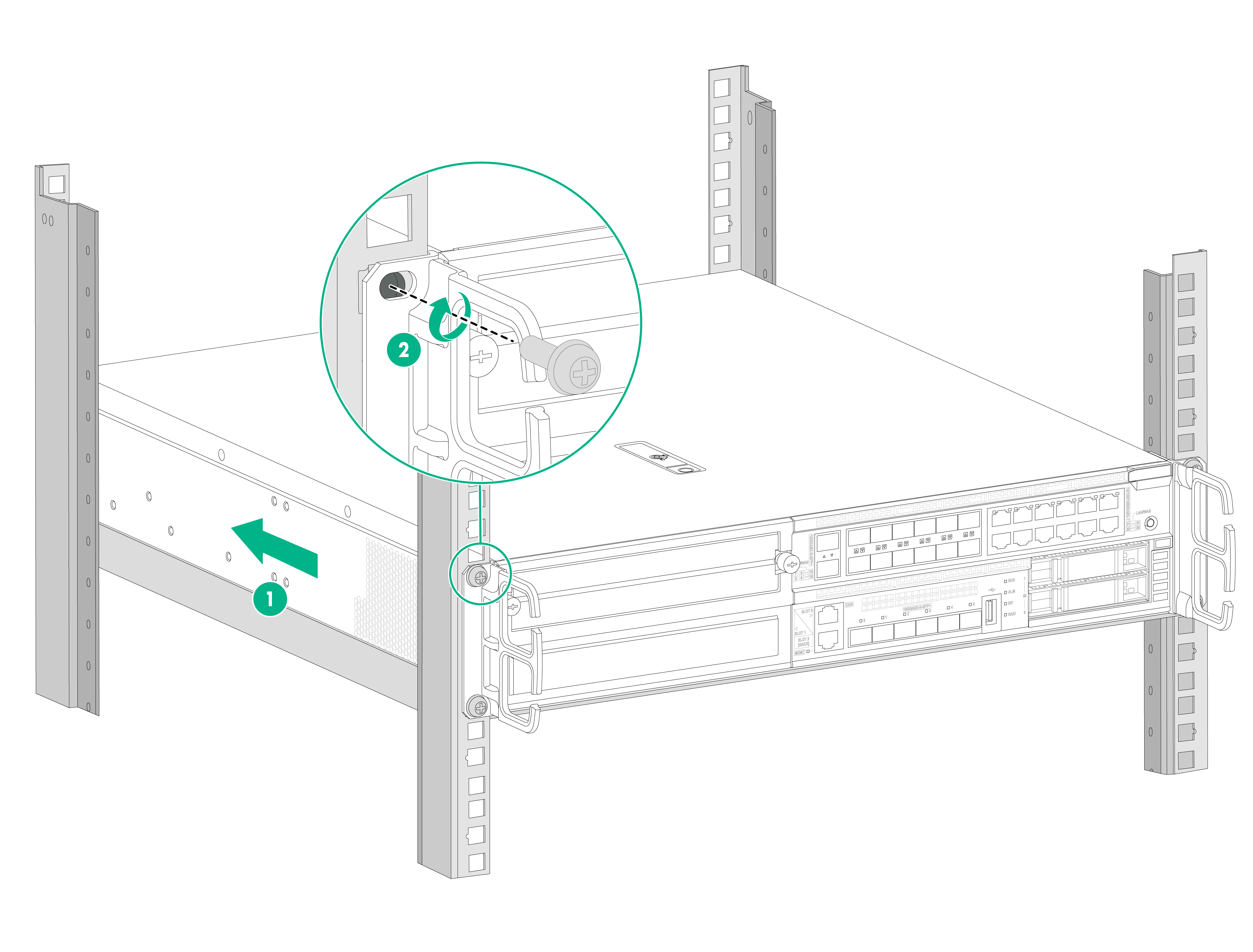
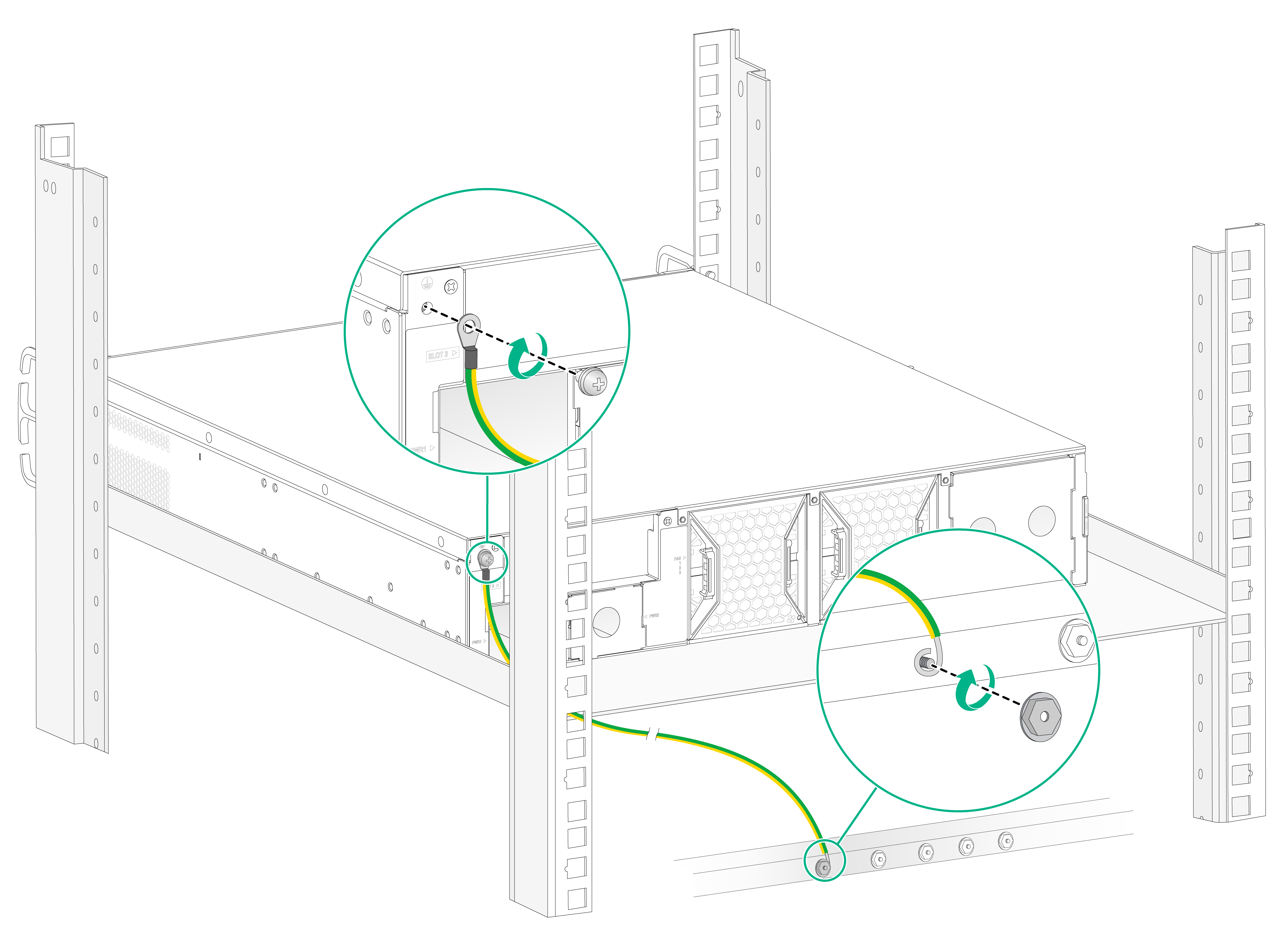
To ground the device by using a grounding terminal on the rack:
1. Make sure the rack is reliably grounded.
2. Remove the grounding screw from the device chassis.
3. Attach the grounding screw to the ring terminal of the grounding cable.
4. Use a Phillips screwdriver to fasten the grounding screw into the grounding hole on the device.
5. Remove the nut from a grounding terminal on the rack.
6. Use a needle-nose pliers to bend a hook at the other end of the grounding cable. Attach the hook to the grounding post, and secure the hook with the nut.
Figure3-13 Grounding the device mounted in a rack
4 Installing internal removable components
|
|
WARNING! To avoid injury, remove the access panel only when the fans stop rotating. |
|
|
CAUTION: · The internal removable components and cables in the chassis are not hot swappable. To install or maintain them, first power off the device. · Before installing an internal removable component, wear an ESD wrist strap and make sure the strap makes good skin contact and is reliably grounded. |
Installing a storage controller
|
|
CAUTION: The storage controllers are not hot swappable. |
|
|
IMPORTANT: After a storage controller is installed, you can configure RAID by using the controller. The device supports RAID levels 0 and 1. For information about RAID configuration, see "Managing RAID." |
To install a storage controller:
1. Wear an ESD wrist strap and make sure the strap makes good skin contact and is reliably grounded.
2. Power off the device.
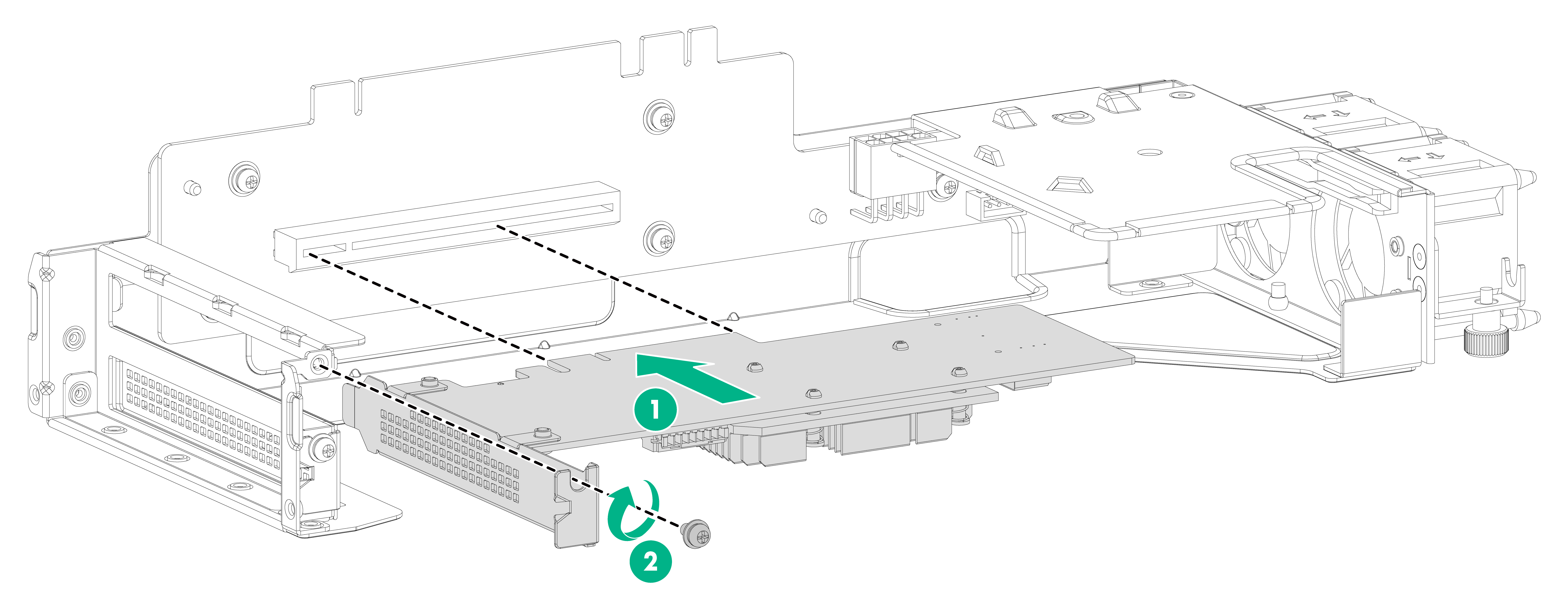
3. Install the storage controller in the riser module:
a. Align the golden plating of the storage controller with the PCIe slot in the riser module and insert the storage controller into the PCIe slot.
b. Use a Phillips screwdriver to fasten the screw provided with the riser module to secure the storage controller to the riser module.
Figure4-1 Installing the storage controller in the riser module
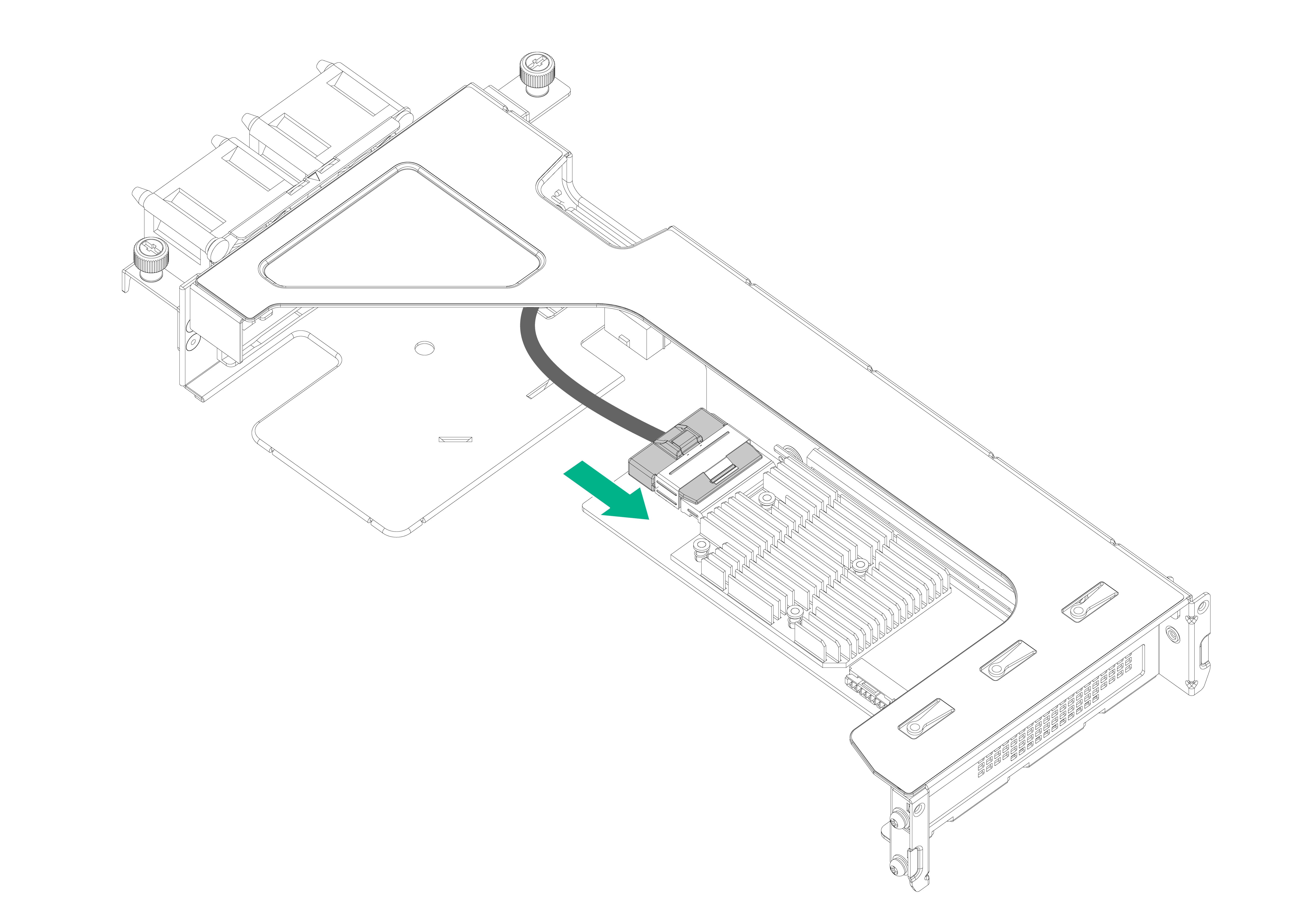
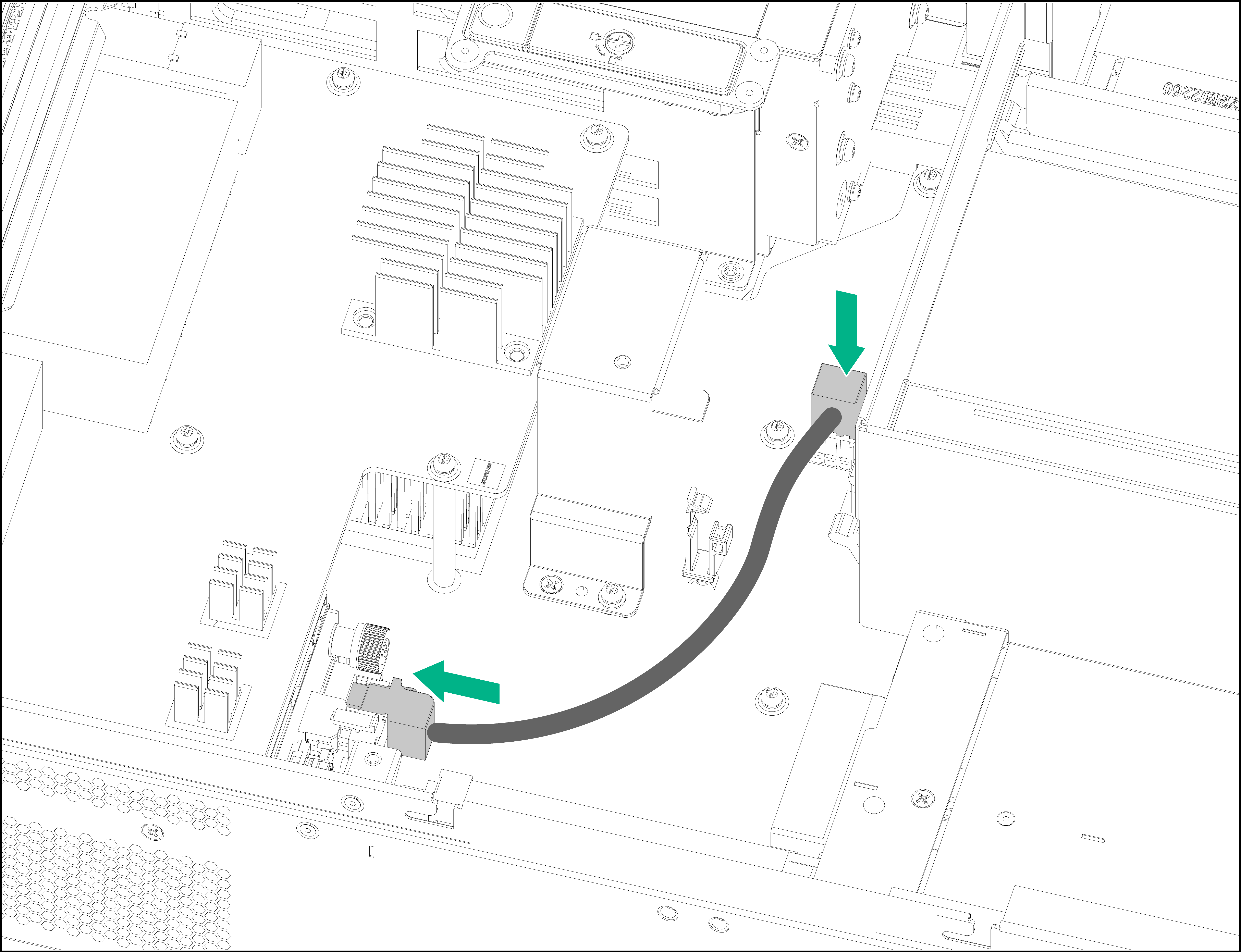
4. Connect one end of the storage controller cable to the storage controller.
Figure4-2 Connecting one end of the storage controller cable to the storage controller
5. Remove the access panel:
a. Face the front panel of the device and use a Phillips screwdriver to unlock the screw on the locking lever.
b. Press the blue unlock button on the locking lever to release the locking lever, and pull the lever upward. The access panel will slide back slightly.
c. Use both hands to hold and lift the access panel.
Figure4-3 Removing the access panel

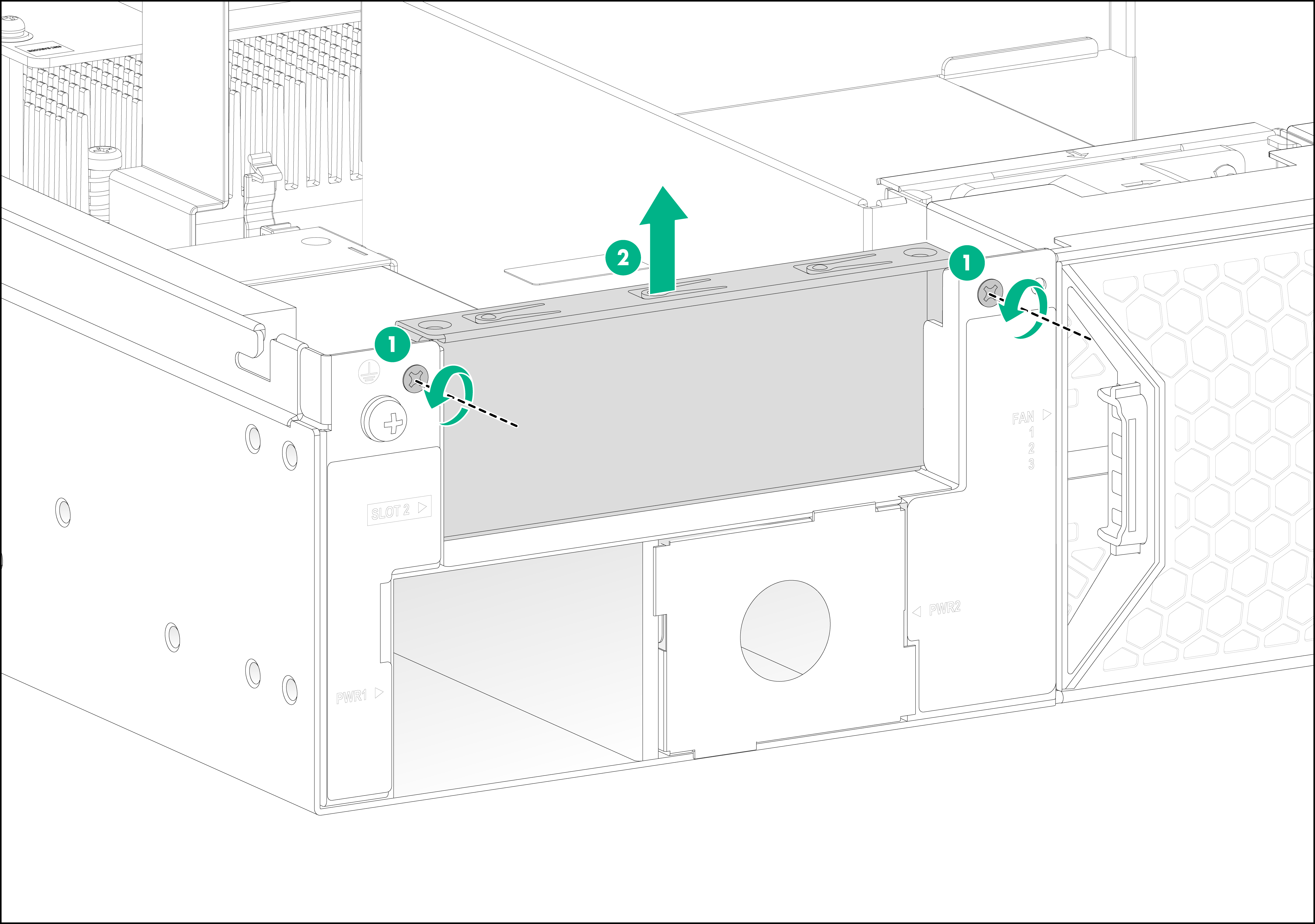
6. Face the rear panel of the device, use a Phillips screwdriver to remove the screws from the riser module blank, and lift the riser module blank from the device.
Figure4-4 Removing the riser module blank
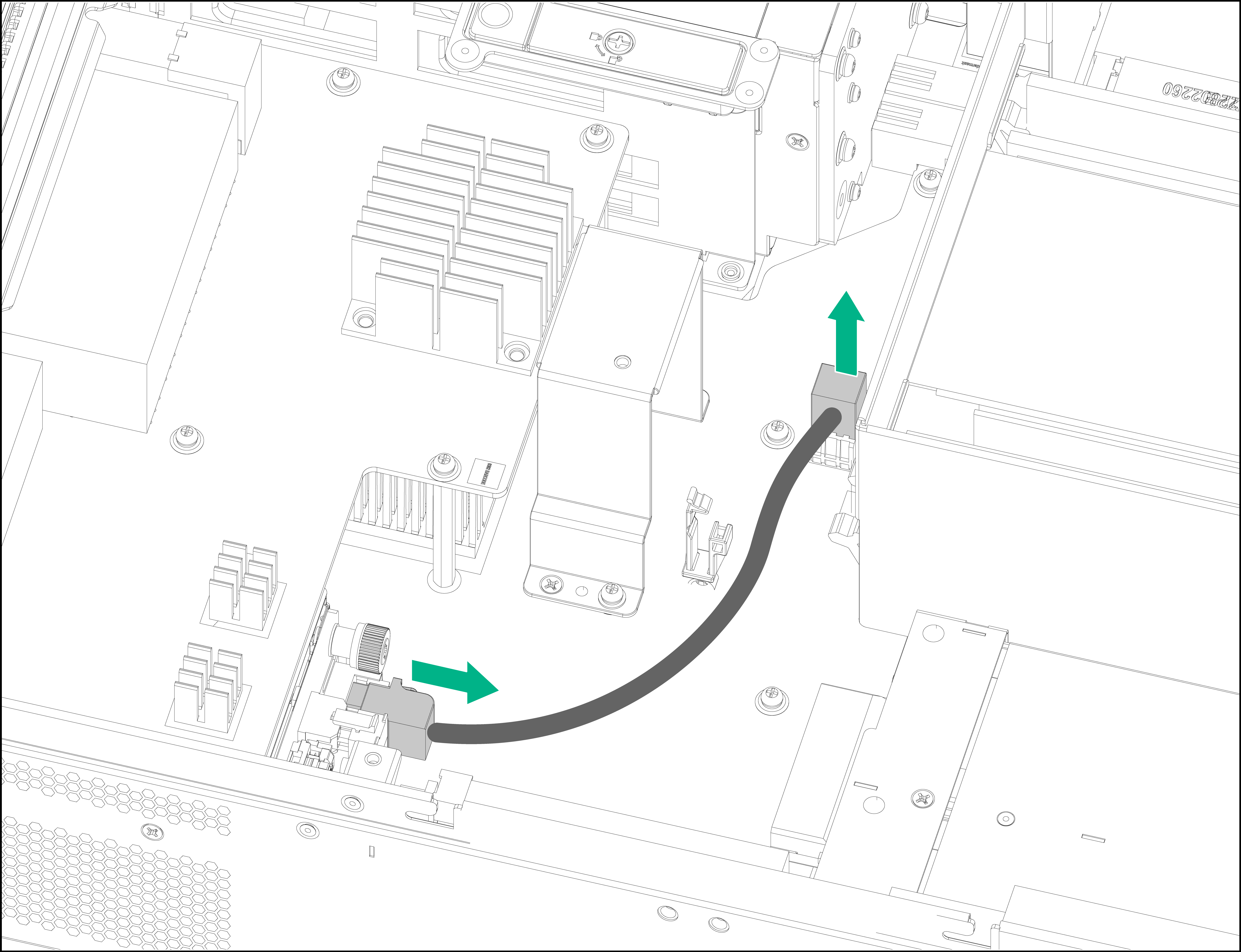
7. Remove the cable from the drive backplane.
The cable is used by the system to identify the external SATA drives. Keep the removed cable secure.
Figure4-5 Removing the cable from the drive backplane
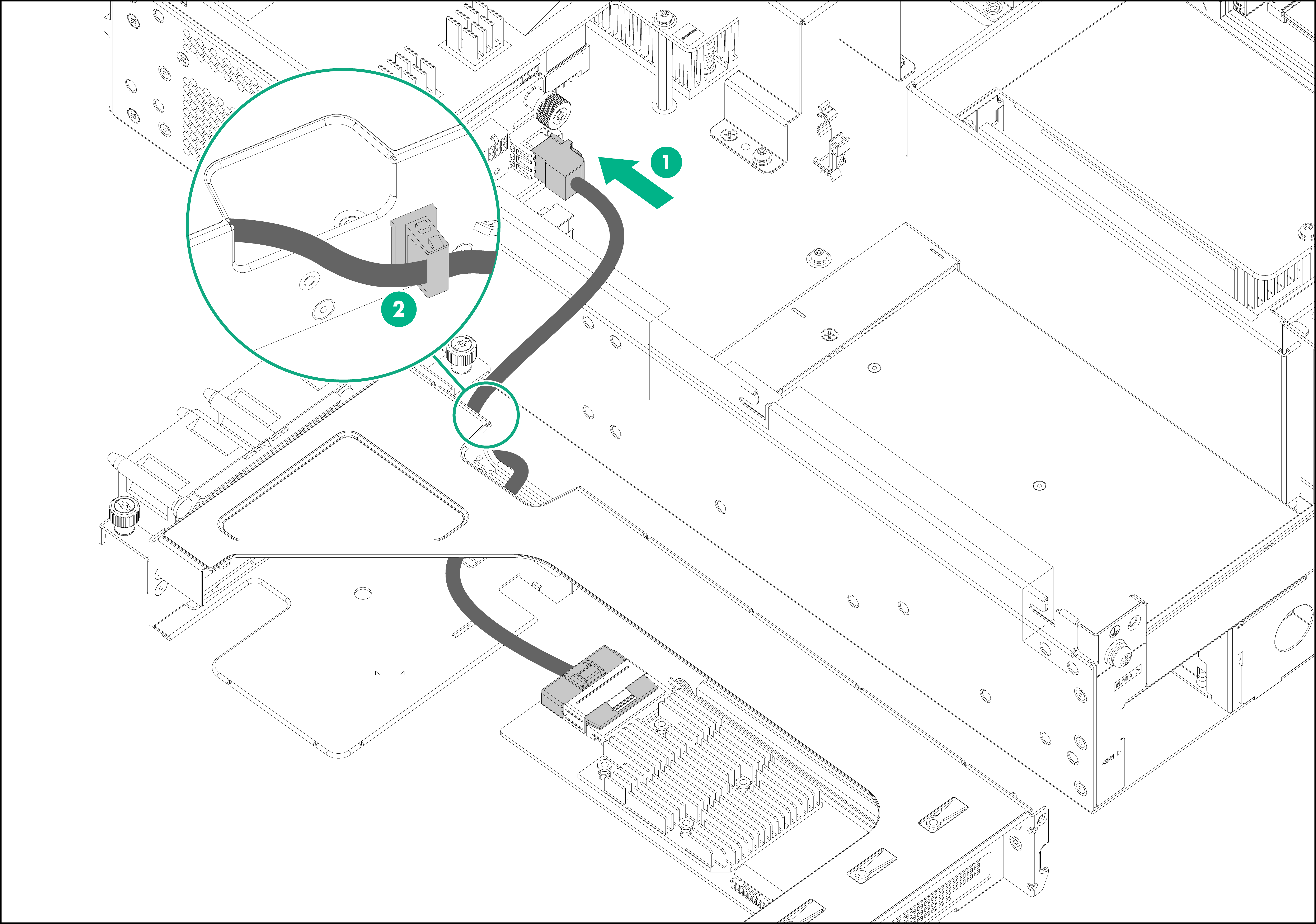
8. Connect the other end of the storage controller cable to the drive backplane and use a cable clamp to secure the storage controller cable to the side panel of the storage controller.
Figure4-6 Connecting the storage controller cable to the drive backplane
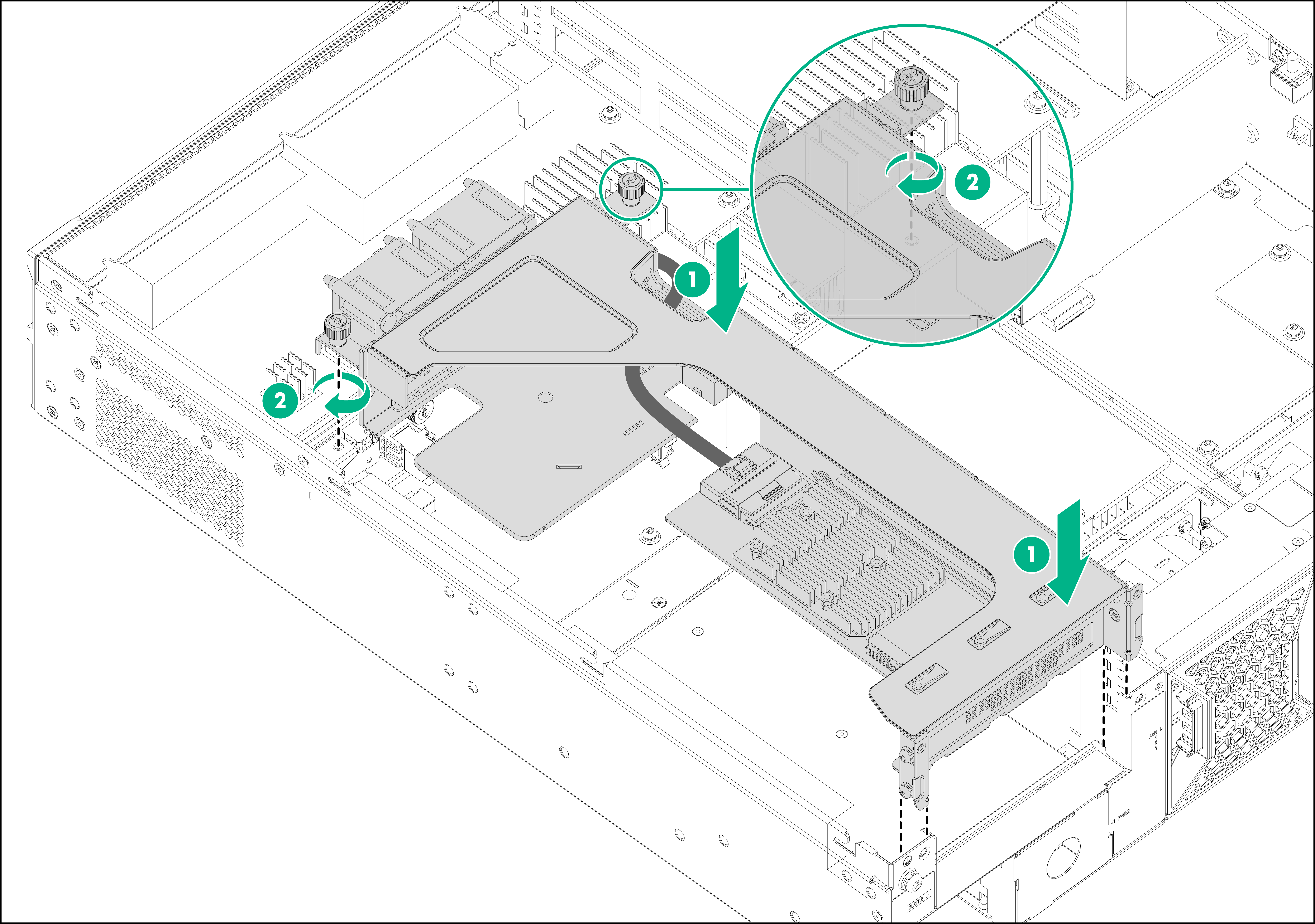
9. Install the riser module installed with the storage controller in the device:
a. Align the front tabs of the riser module with the guide rails on the system board and align the captive screw with the screw hole on the system board.
b. Align the golden plating of the riser module with the PCIe riser connector on the main board, and insert the riser module vertically onto the system board.
c. Fasten the captive screws to secure the riser module to the system board.
Figure4-7 Installing the riser module in the device
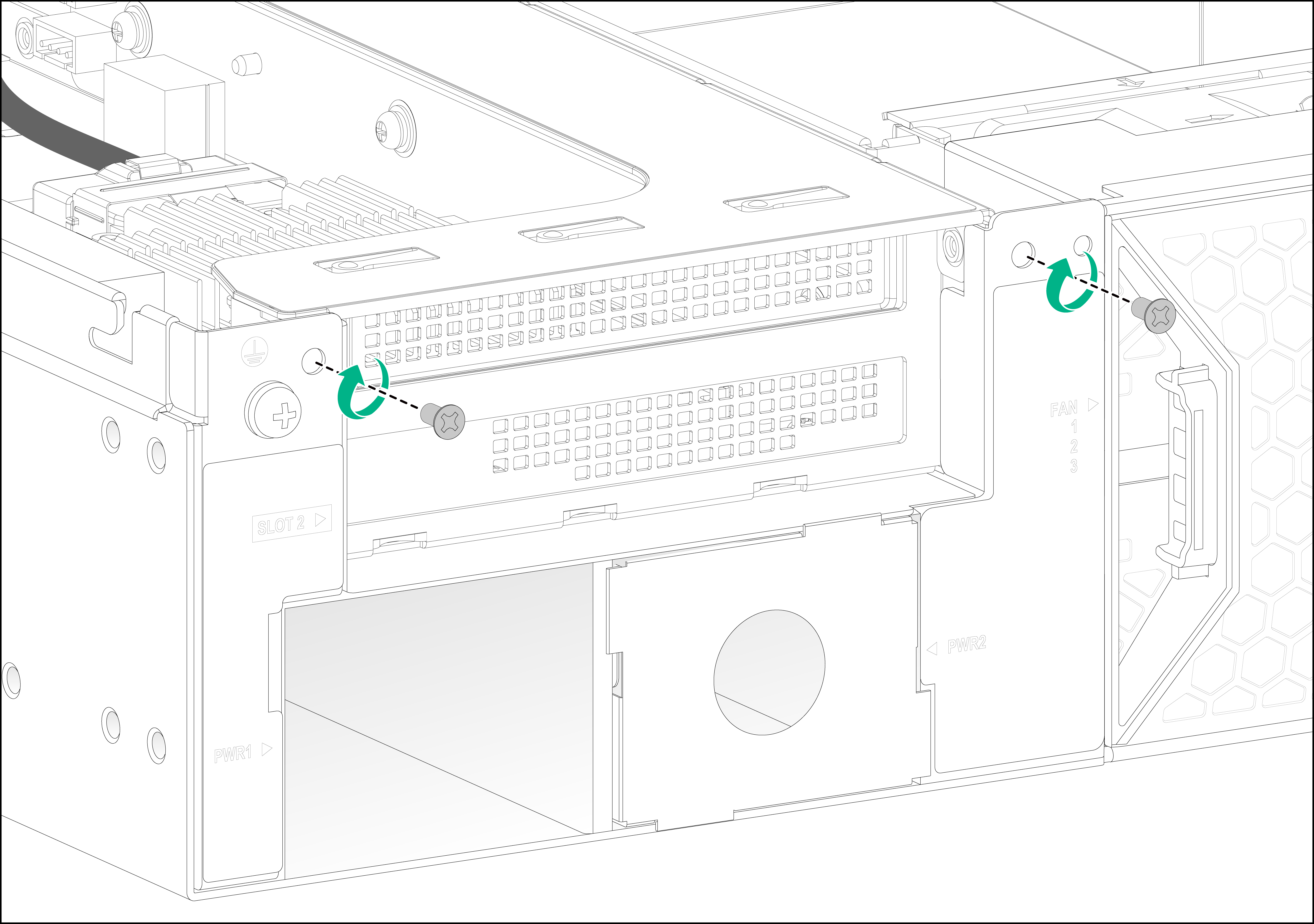
10. Fasten the screws with a Phillips screwdriver to secure the riser module to the chassis.
Figure4-8 Securing the riser module to the device
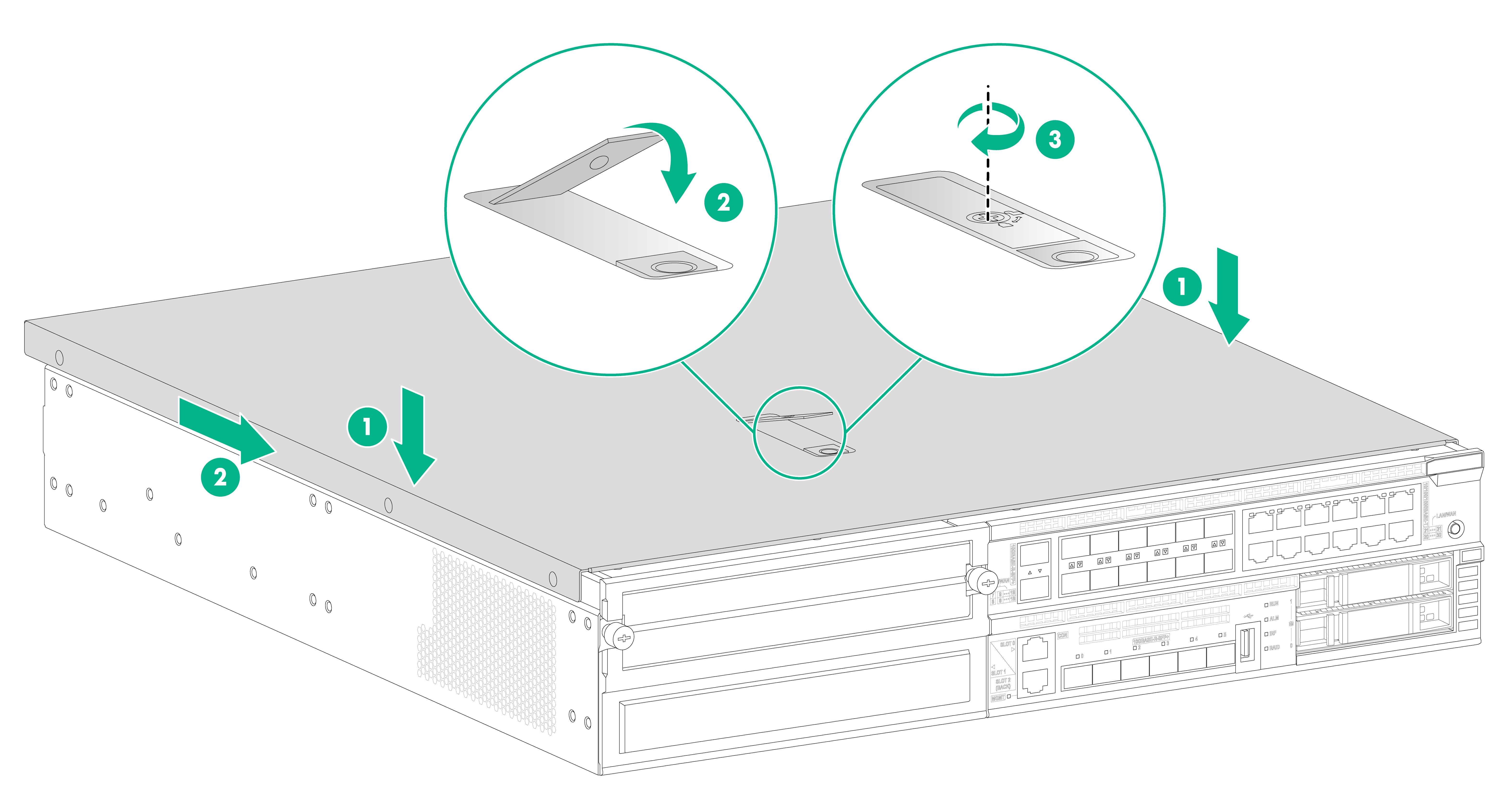
11. Install the access panel:
a. Face the front panel of the device, place the access panel on top of the device chassis, and align the pegs inside the access panel with the slots on the device side panels.
b. Press the locking lever downwards until it is locked in place.
c. Fasten the screw on the locking lever with a Phillips screwdriver to lock the locking lever.
Figure4-9 Installing the access panel
Installing a GPU
|
|
CAUTION: · The GPUs are not hot swappable. · For a GPU to operate correctly on the device, you must install two 450W power supplies to supply power simultaneously to the device. |
|
|
IMPORTANT: · A GPU support bracket and three screws are shipped with a riser module. Keep them secure before installing a GPU. · Use the GPU support bracket and screws provided with the riser module to install a GPU in the riser module. The GPU support bracket and screws provided with a GPU might not fit the riser module structure. |
To install a GPU:
1. Wear an ESD wrist strap and make sure the strap makes good skin contact and is reliably grounded.
2. Power off the device.
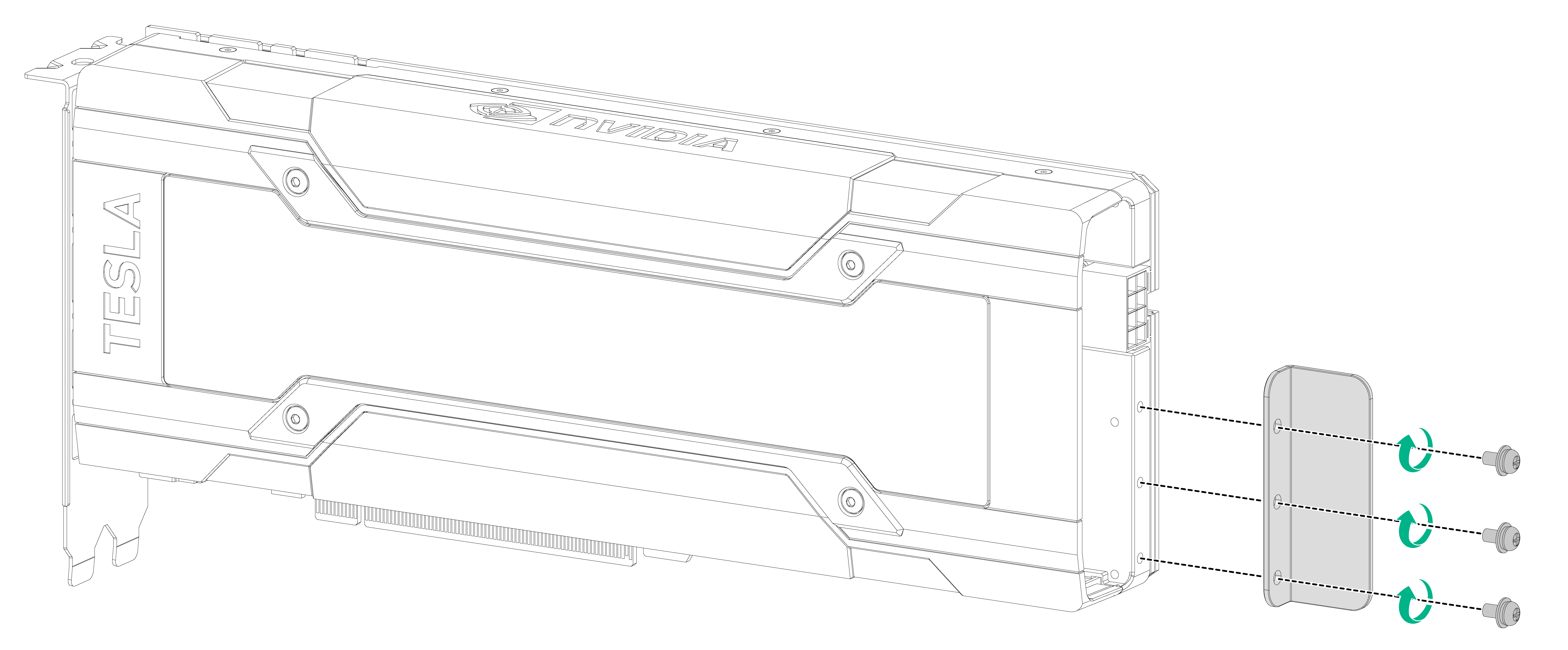
3. Attach the GPU support bracket to the GPU. Align the three screw holes in the GPU support bracket with the installation holes in the GPU, and then use screws to attach the GPU support bracket to the GPU.
Figure4-10 Attaching the GPU support bracket to the GPU
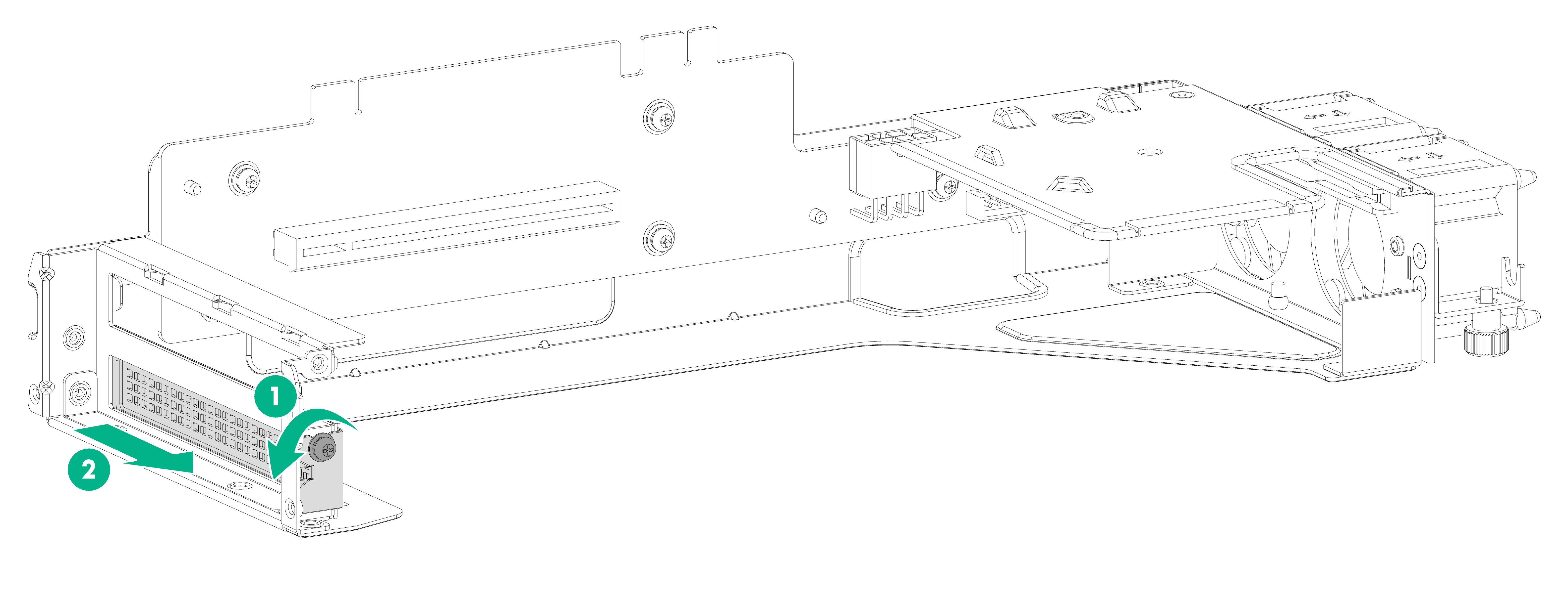
4. Remove the module blank from the riser module. Use a Phillips screwdriver to loosen the screw on the module blank and then pull the module blank slowly out of the riser module.
Figure4-11 Removing the module blank from the riser module
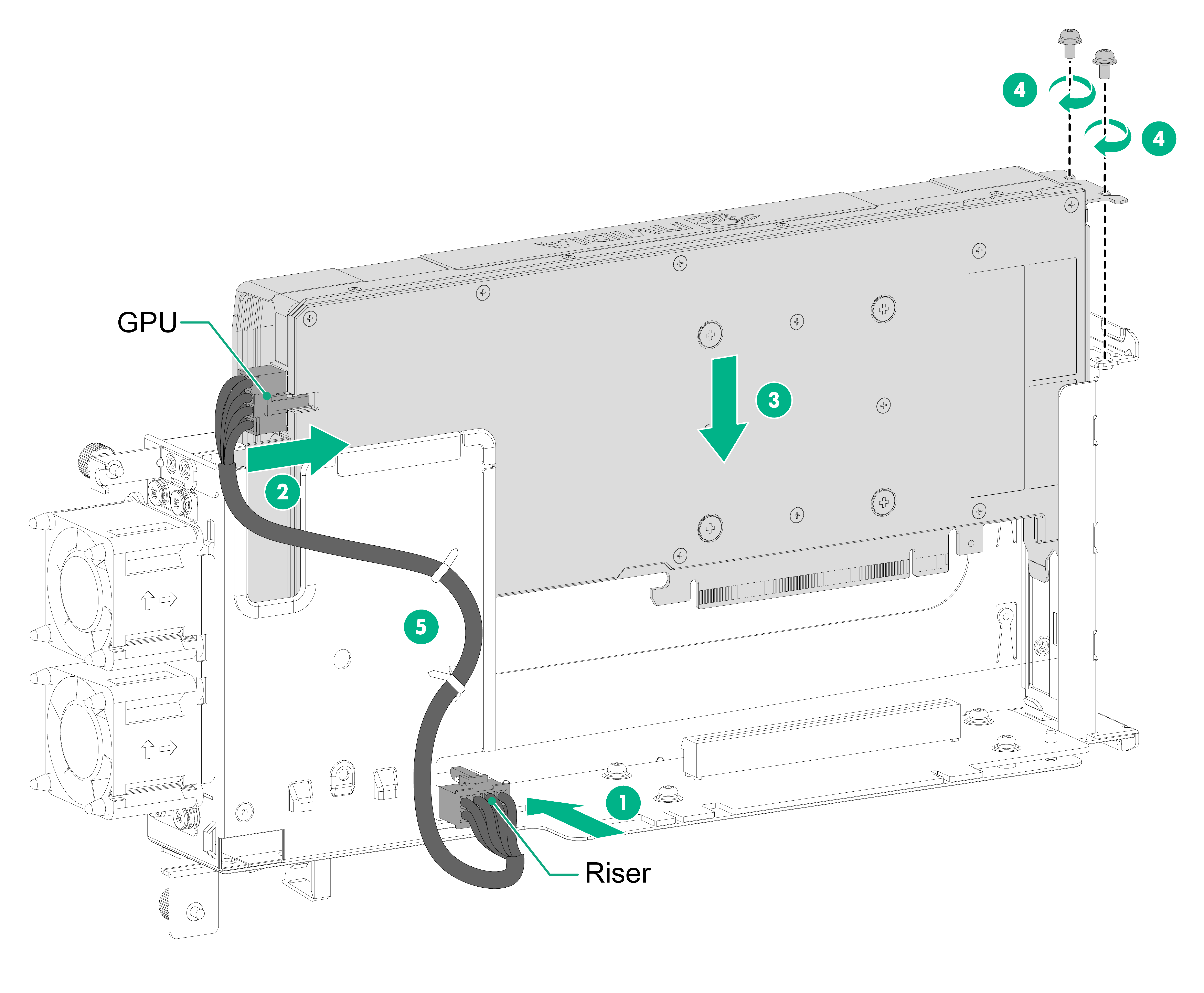
5. Install the GPU in the riser module and connect the GPU power cord:
a. Connect the end marked "Riser" of the GPU power cord to the riser module and then connect the other end of the power cord to the GPU module.
b. Insert the GPU into PCIe slot along the guide rails and fasten the screws to secure the GPU to the riser module.
c. Use the cable ties provided with the riser module to secure the GPU power cord to the cable tie holders on the side panel.
Figure4-12 Installing the GPU in the riser module
6. Remove the access panel. For more information, see "Installing a storage controller."
7. Remove the riser module blank. For more information, see "Installing a storage controller."
8. Install the riser module installed with the GPU in the device. With a GPU or storage controller installed, the riser module installation procedure is the same. For more information, see "Installing a storage controller."
9. Use screws to secure the riser module to the chassis. For more information, see "Installing a storage controller."
10. Install the access panel. For more information, see "Installing a storage controller."
Installing a DIMM
|
|
CAUTION: The DIMMs are not hot swappable. |
|
|
IMPORTANT: For system identification, use the DIMMs recommended by H3C. |
To install a DIMM:
1. Wear an ESD wrist strap and make sure the strap makes good skin contact and is reliably grounded.
2. Power off the device.
3. Remove the access panel. For more information, see "Installing a storage controller."
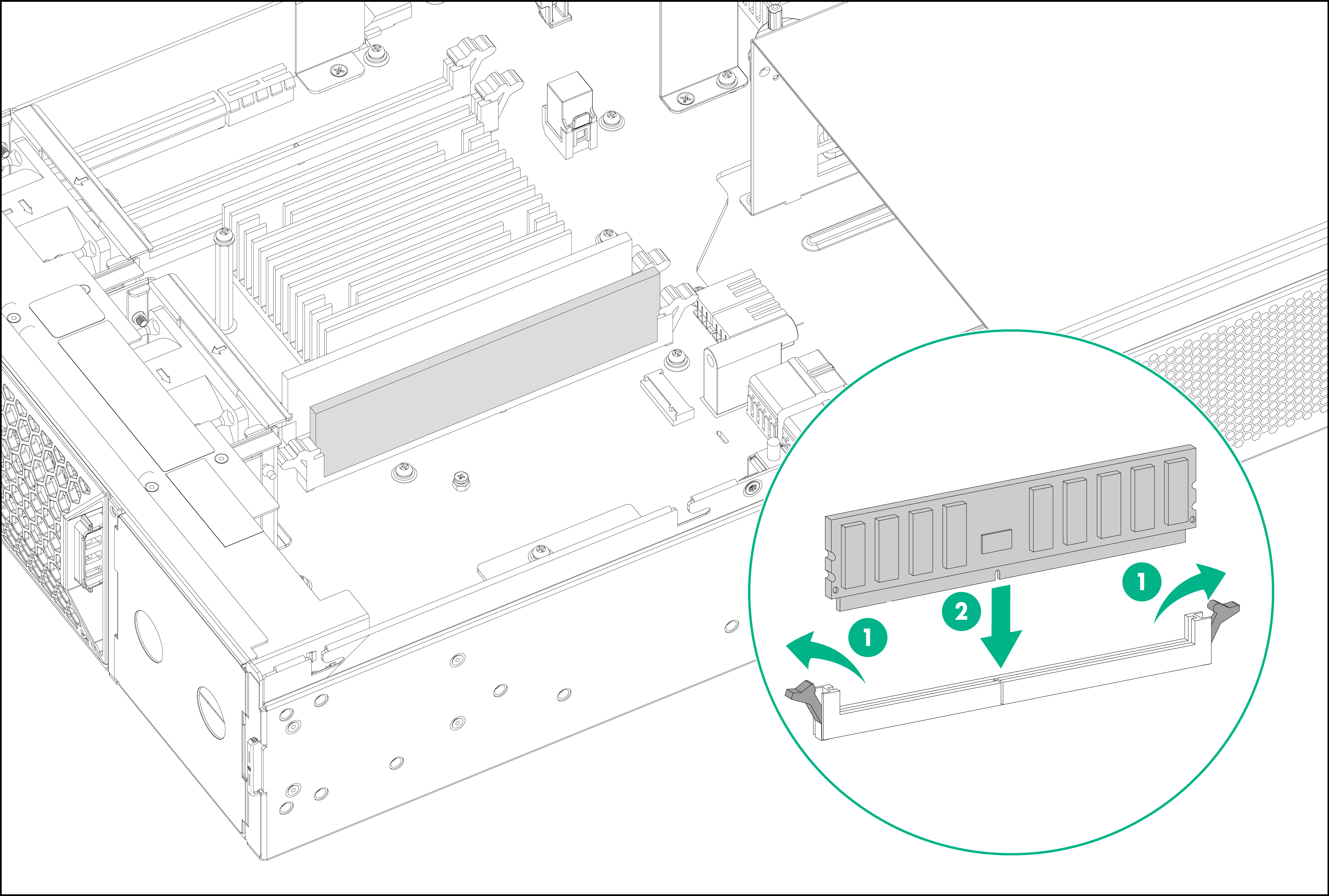
4. Install a DIMM:
a. Identify the location of the DIMM slot and open the DIMM slot latches.
b. Align the notch on the DIMM with the connector key in the DIMM slot and press the DIMM into the socket until the latches lock the DIMM in place.
5. Install the access panel. For more information, see "Installing a storage controller."
Installing an M.2 SSD drive
|
|
CAUTION: The M.2 SSD drives are not hot swappable. |
|
|
IMPORTANT: · For system identification, use M.2 SSD drives recommended by H3C. · The M.2 SSD drive screw is shipped with the document bag for the chassis. Before installing an M.2 SSD drive, keep the screw secure. |
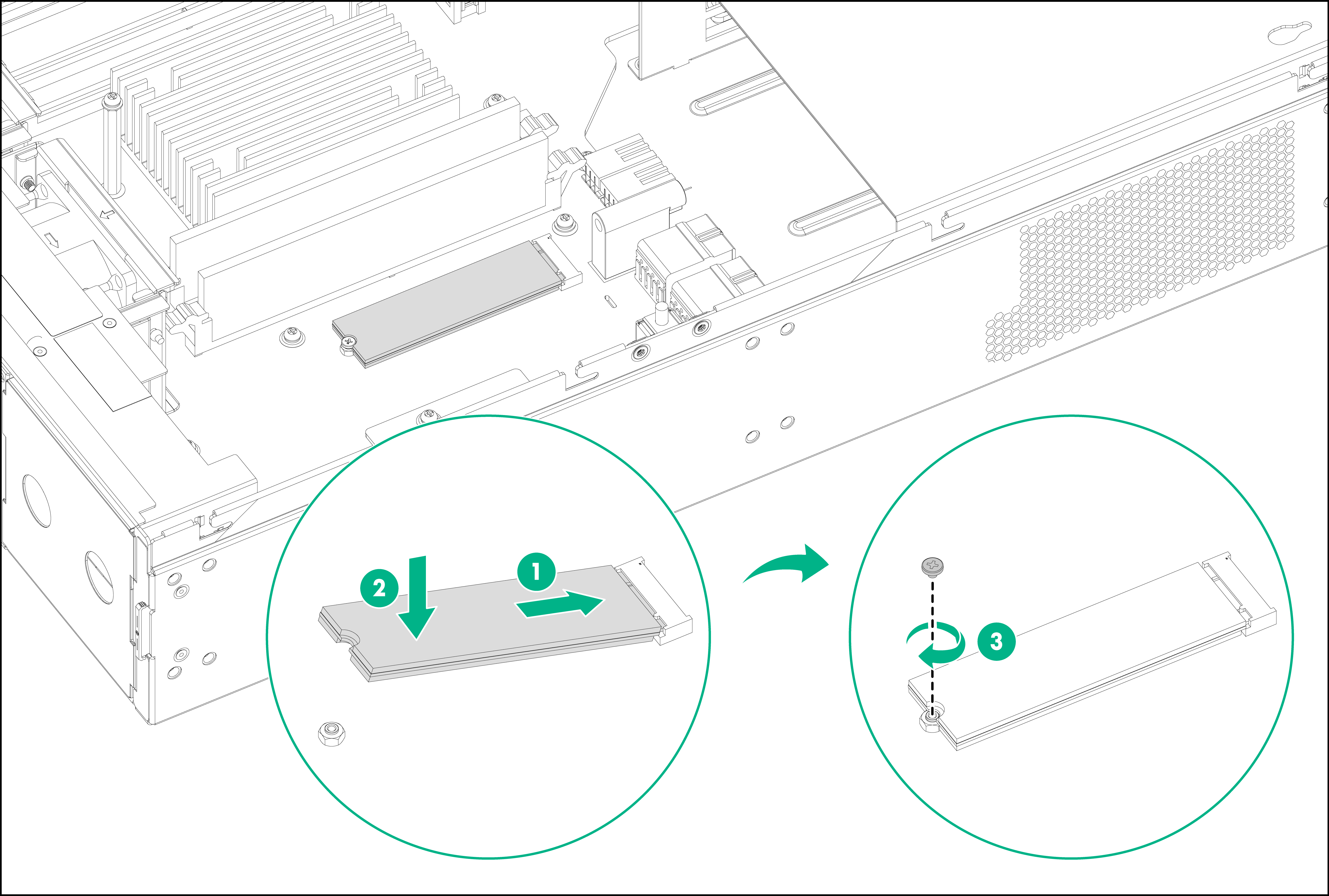
The device supports M.2 SSD drives with dimensions of 22 × 80 mm (0.87 × 3.15 in) and M.2 SSD drives with dimensions of 22 × 60 mm (0.87 × 2.36 in). To install an M.2 SSD drive with dimensions of 22 × 60 mm (0.87 × 2.36 in), adjust the stud location in the system board. The following procedure installs an M.2 SSD drive with dimensions of 22 × 80 mm (0.87 × 3.15 in).
To install an M.2 SSD drive:
1. Wear an ESD wrist strap and make sure the strap makes good skin contact and is reliably grounded.
2. Power off the device.
3. Remove the access panel. For more information, see "Installing a storage controller."
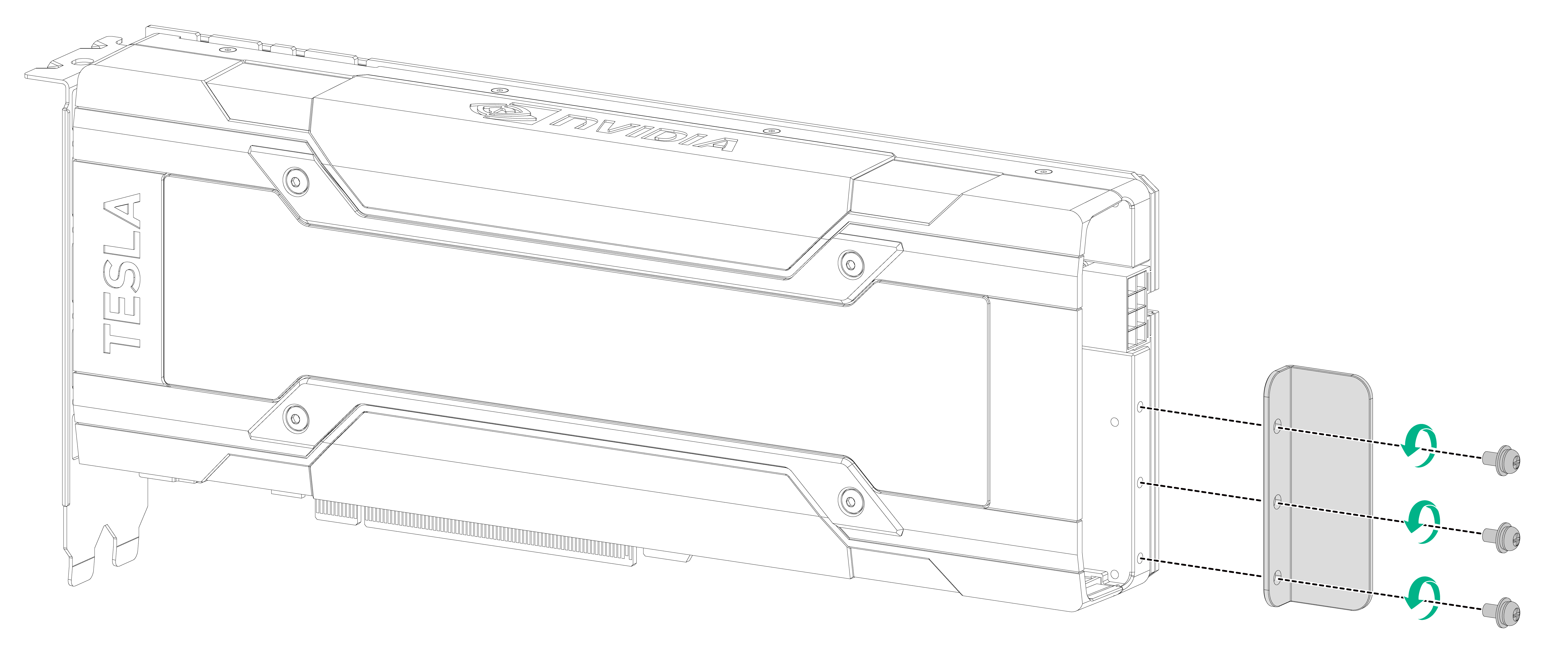
4. Insert the golden plating end of the M.2 SSD drive slowly into the M.2 slot at an angle.
5. Slightly press the other end of the golden plating until the golden plating of the M.2 SSD drive is in close contact with the connector in the M.2 slot.
6. Use a Phillips screwdriver to screw the M.2 SSD drive into place.
Figure4-14 Installing an M.2 SSD drive
7. Install the access panel. For more information, see "Installing a storage controller."
5 Installing external removable components
|
|
CAUTION: · Install a module or filler panel in each slot. Make sure no slot is empty during the device operation. · Keep the filler panels, package boxes, and package bags secure for future use. · Do not hold the handle of a power supply or of a module to move the device. Doing so might cause device damage. |
Installing MIC-X interface cards
|
|
CAUTION: · Do not install a MIC-X interface card when the device is operating. · To avoid configuration loss of a MIC-X interface card, first install it on a FIP module, and then install the FIP module with it on the device. · To install two MIC-X interface cards on the FIP module, install one first in slot 2 and then another in slot 1 as a best practice. Otherwise, the access panel of the device might hinder the interface card installation in slot 2. If you have installed an interface card in slot 1, you must press down the ejector levers of the interface card and then insert it into slot 2 slowly. |
To install an MIC-X interface card:
1. Wear an ESD wrist strap and make sure the strap makes good skin contact and is reliably grounded.
2. Identify the target slot on the FIP module.
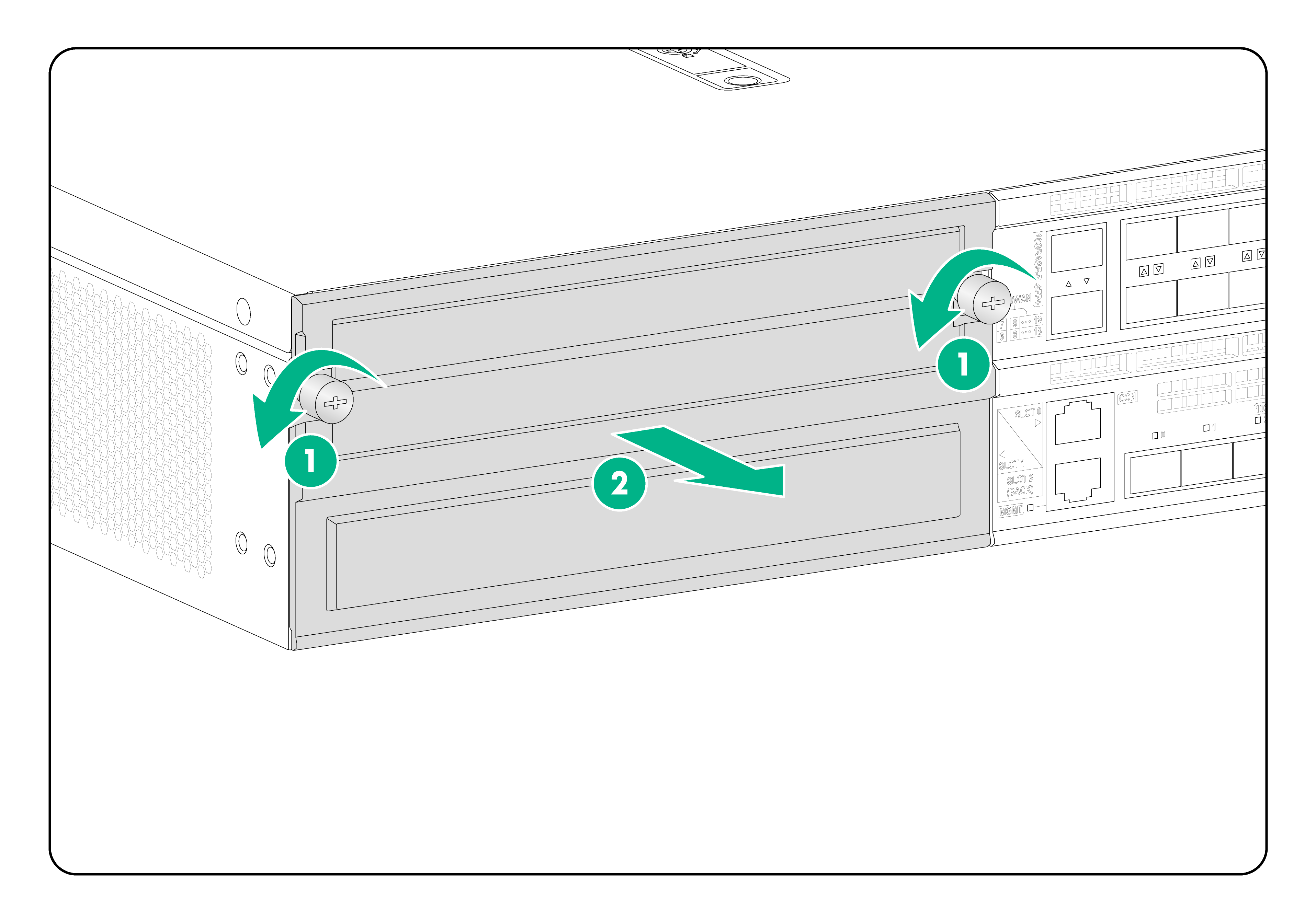
3. Use a Phillips screwdriver to loosen the captive screws on the filler panel. Insert a flat-head screwdriver into the hole on the filler panel to pull the filler panel out the slot.
Keep the removed filler panel secure.
Figure5-1 Removing the filler panel
4. Open the ejector levers on the MIC-X interface card and push the MIC-X interface card slowly into the slot along the guide rails.
5. Close the ejector levers until the MIC-X interface card is securely seated in the slot.
6. Use a Phillips screwdriver to fasten the captive screws on the MIC-X interface card.
Figure5-2 Installing a MIC-X interface card
7. Install the FIP with the MIC-X interface card in the target slot on the device. For the installation procedure, see "Installing a FIP module."
Installing a FIP module
|
|
CAUTION: · The FIP modules are hot swappable. · If you are to install a MIC-X interface card on the device, first install it on a FIP module, and then install the FIP module with it on the device. |
To install a FIP module:
1. (Optional.) Install MIC-X interface cards on the FIP module. For the MIC-X interface card installation procedure, see "Installing MIC-X interface cards."
2. Wear an ESD wrist strap and make sure the strap makes good skin contact and is reliably grounded.
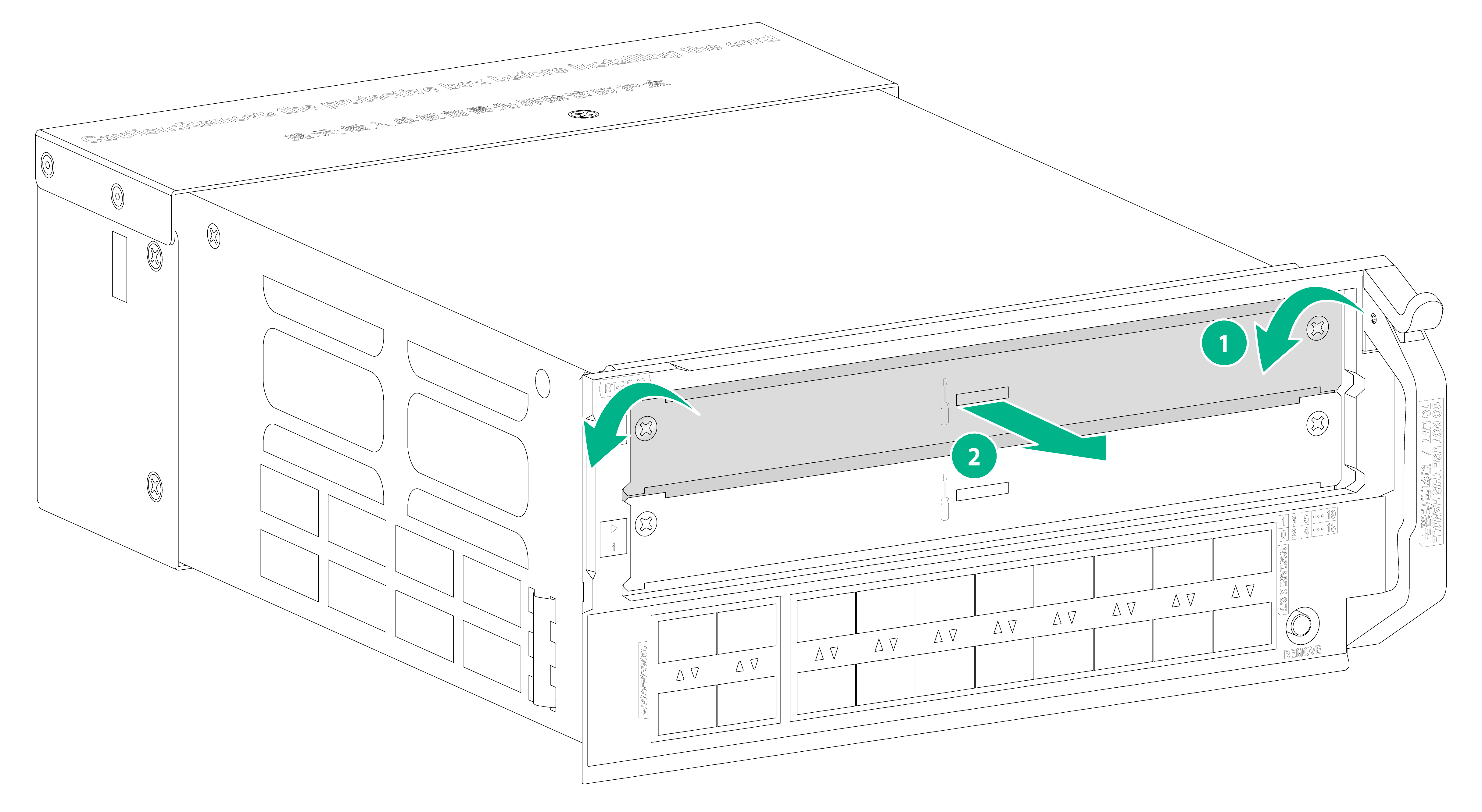
3. Face the front panel of the device, use a Phillips screwdriver to loosen the captive screws on the filler panel, and then remove the filler panel.
Figure5-3 Removing the filler panel
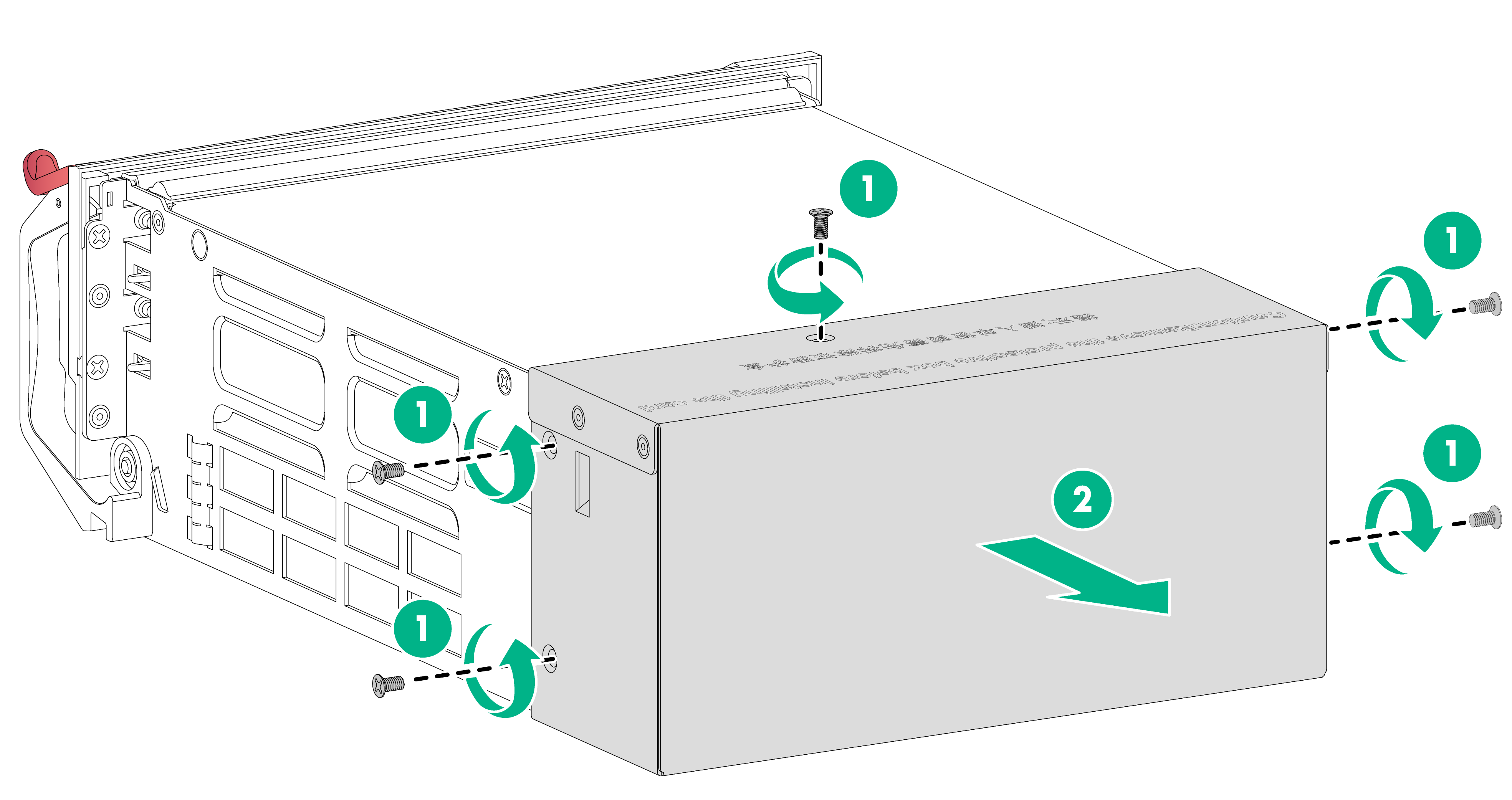
4. (Optional.) If the FIP module has a protective cover at the connector end, remove the cover and keep it secure.
Figure5-4 Removing the protective cover
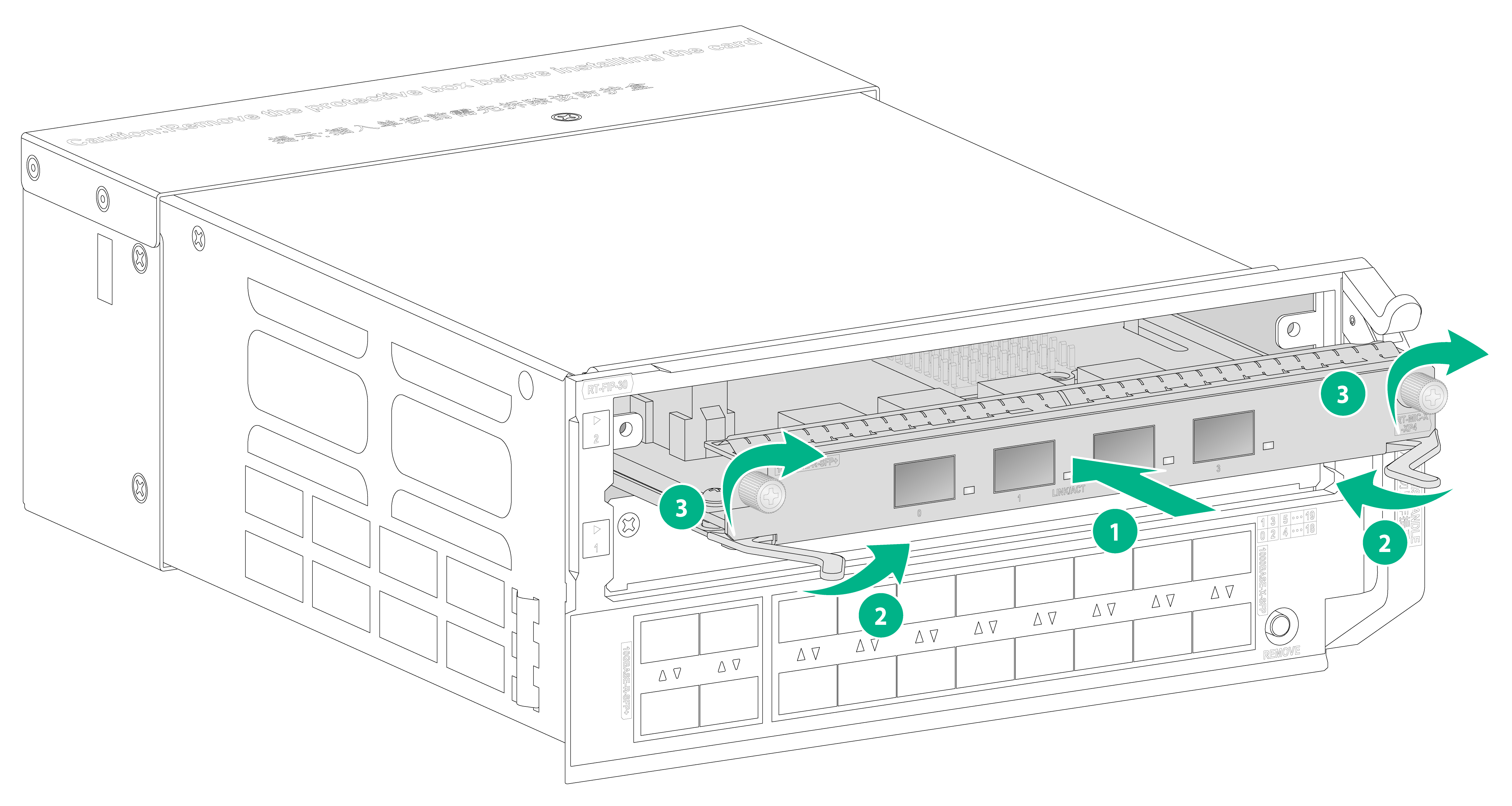
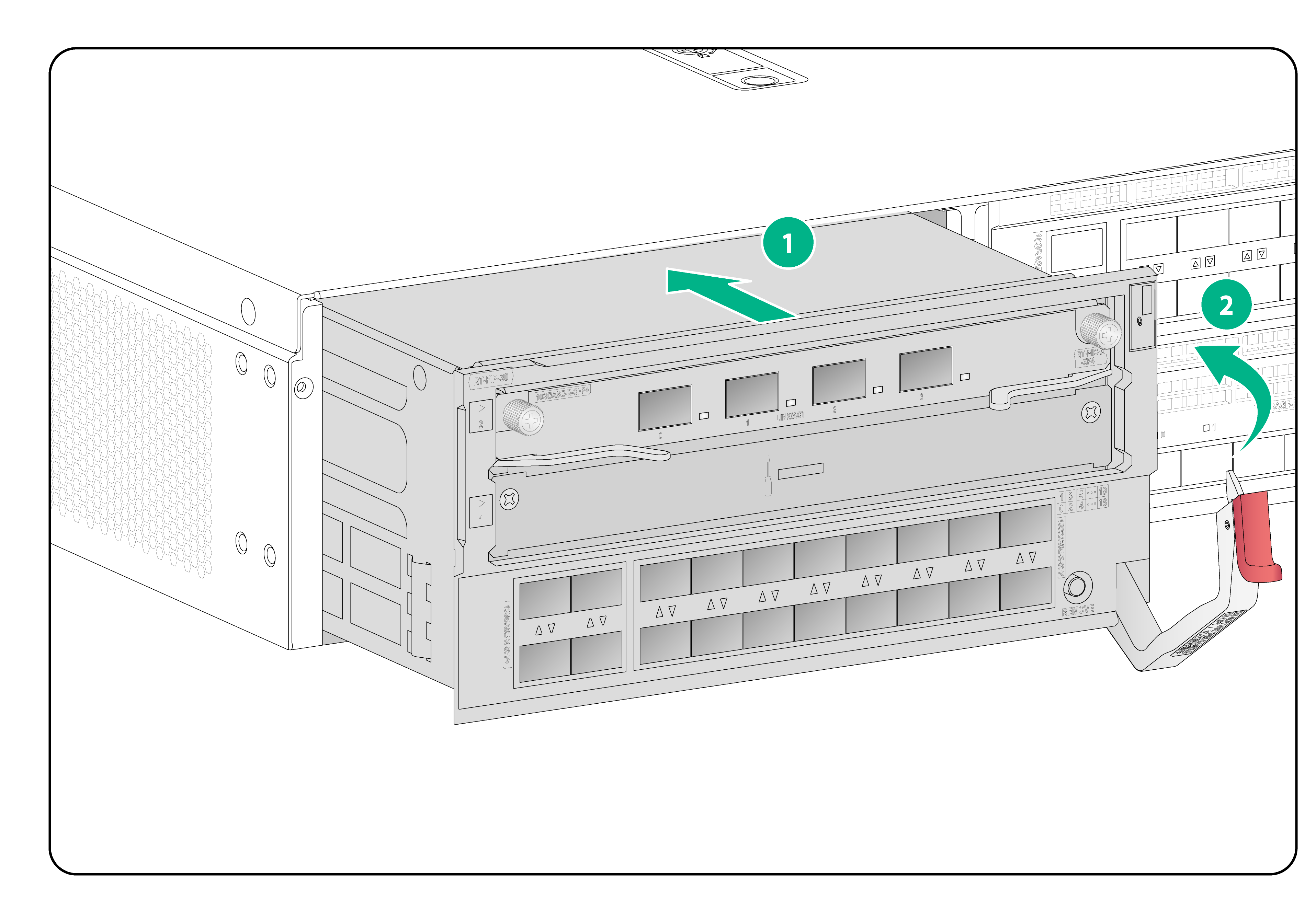
5. Press the red latch to disengage the ejector lever from the FIP module.
6. Holding the ejector lever by one hand and supporting the FIP module by the other, push the FIP module slowly into the slot along the guide rails.
7. Close the ejector lever until the FIP module is securely seated in the slot.
Figure5-5 Installing a FIP module
Installing SATA drives
|
|
CAUTION: · The SATA drives are hot swappable. You can install a SATA drive, or remove a SATA drive in RAID configuration as indicated by the LED without power off the device. To remove a SATA drive not in RAD configuration, you must first power off the device. · Before using a SATA drive, execute the fdisk and format commands to partition the SATA drive and clear all data in the SATA drive. · For system identification, use SATA drives dedicated for the device. · Hold a SATA drive by two sides and do not touch any components of the drive, or squeeze, shake, or strike the drive. · To prevent ESD damage, install a filler panel in a SATA drive slot not in use. |
To install a SATA drive:
1. Wear an ESD wrist strap and make sure the strap makes good skin contact and is reliably grounded.
2. Remove the filler panel from the SATA drive slot and keep the removed filler panel secure.
3. Press the red button on the SATA drive tray to release the locking lever.
4. Push the SATA drive slowly into the slot along the guide rails and then close the locking lever.
Figure5-6 Installing a SATA drive
Installing power supplies
|
|
WARNING! Provide a separate circuit breaker for each power supply. |
|
|
CAUTION: · Do not install AC and DC power supplies on the same device. · To prevent damage to the connectors inside the chassis, insert the power supply gently. If you encounter a hard resistance while inserting the power supply, pull out the power supply and insert it again. |
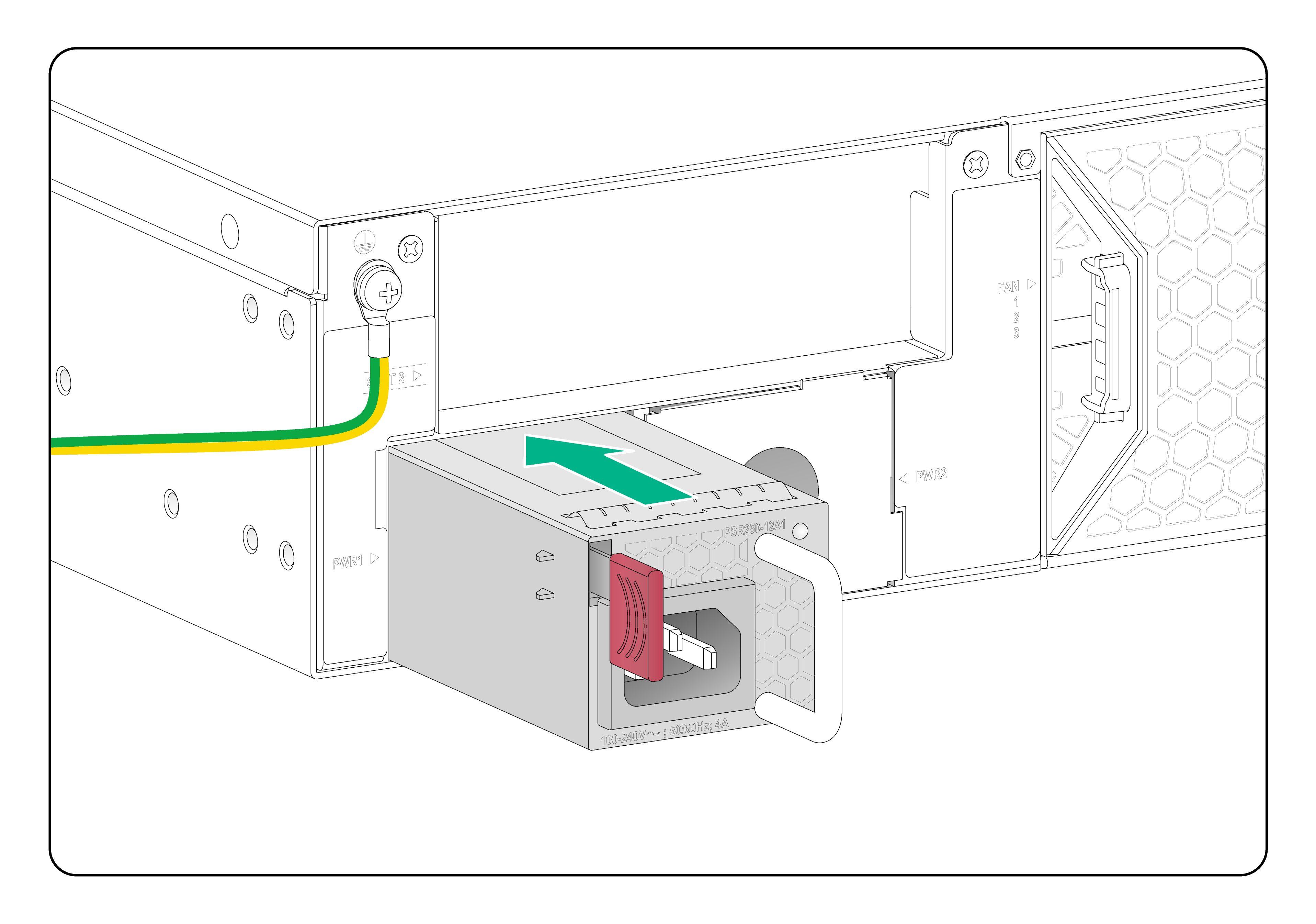
To avoid device damage or bodily injury, install a power supply as shown in Figure5-7.
Figure5-7 Installation procedure
![]()
The installation procedure is similar for AC and DC power supplies. This following procedure installs a PSR250-12A1 AC power supply.
To install a power supply:
1. Wear an ESD wrist strap and make sure the strap makes good skin contact and is reliably grounded.
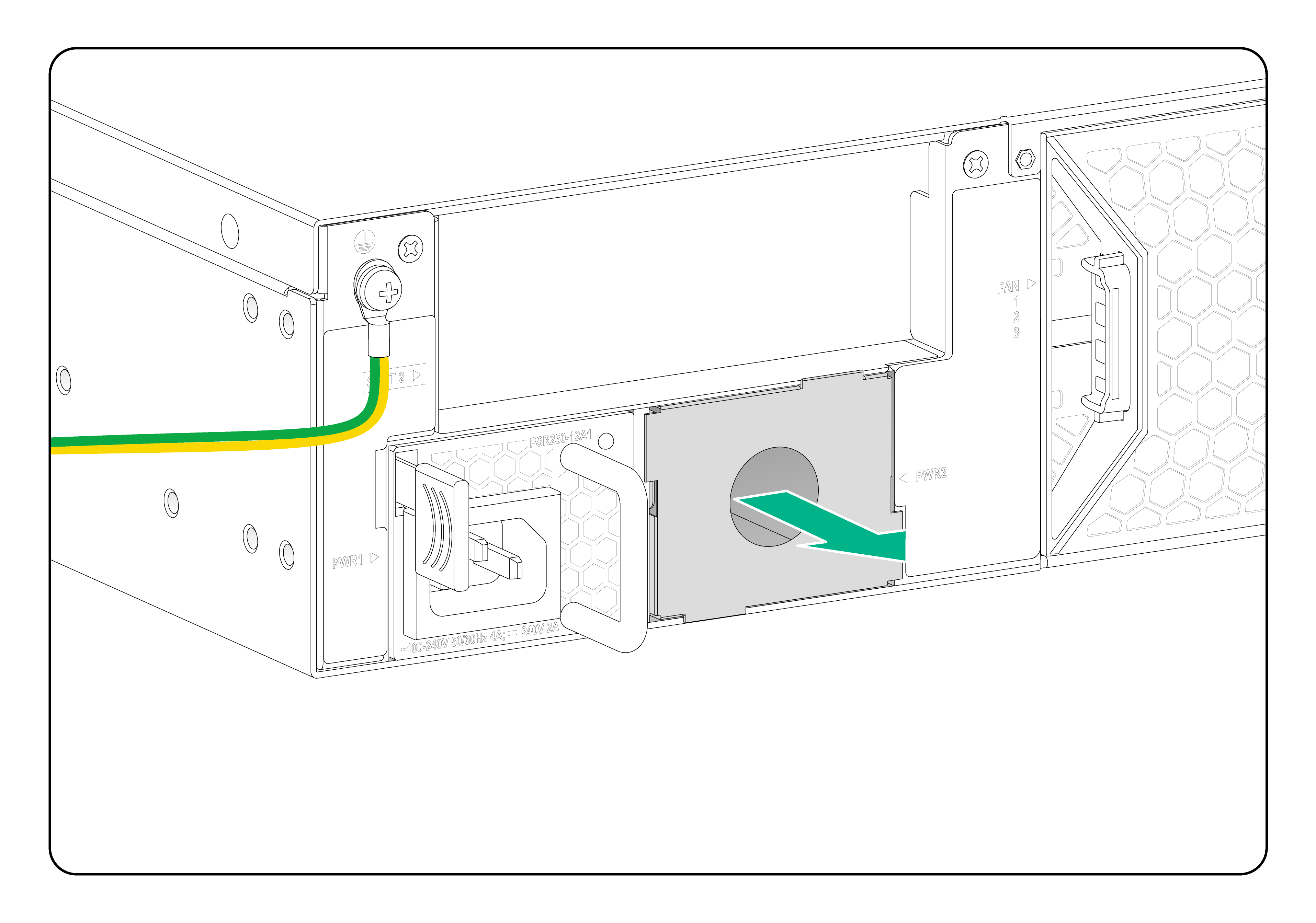
2. Remove the filler panel from the target power supply slot, if any.
To install the power supply in slot PWR2, first remove the filler panel from the slot as shown in Figure5-8.
Figure5-8 Removing the filler panel from a power supply slot
3. Unpack the power supply and verify that the power supply model is correct.
4. Correctly orient the power supply with the power supply slot. Grasp the handle of the power supply with one hand and support its bottom with the other, and slide the power supply slowly along the guide rails into the slot.
The slot is foolproof. If you cannot insert the power supply into the slot, re-orient the power supply rather than use excessive force to push it in.
Figure5-9 Installing a power supply
6 Connecting power cords
|
|
CAUTION: · Before connecting a power cord, make sure the device is reliably grounded. · Use a separate circuit breaker for each power input. Before connecting a power cord, turn off the circuit breaker for the power input. · Each power supply is provided with a power cord. Use this power cord other than other power cords to connect the power supply to a power source. |
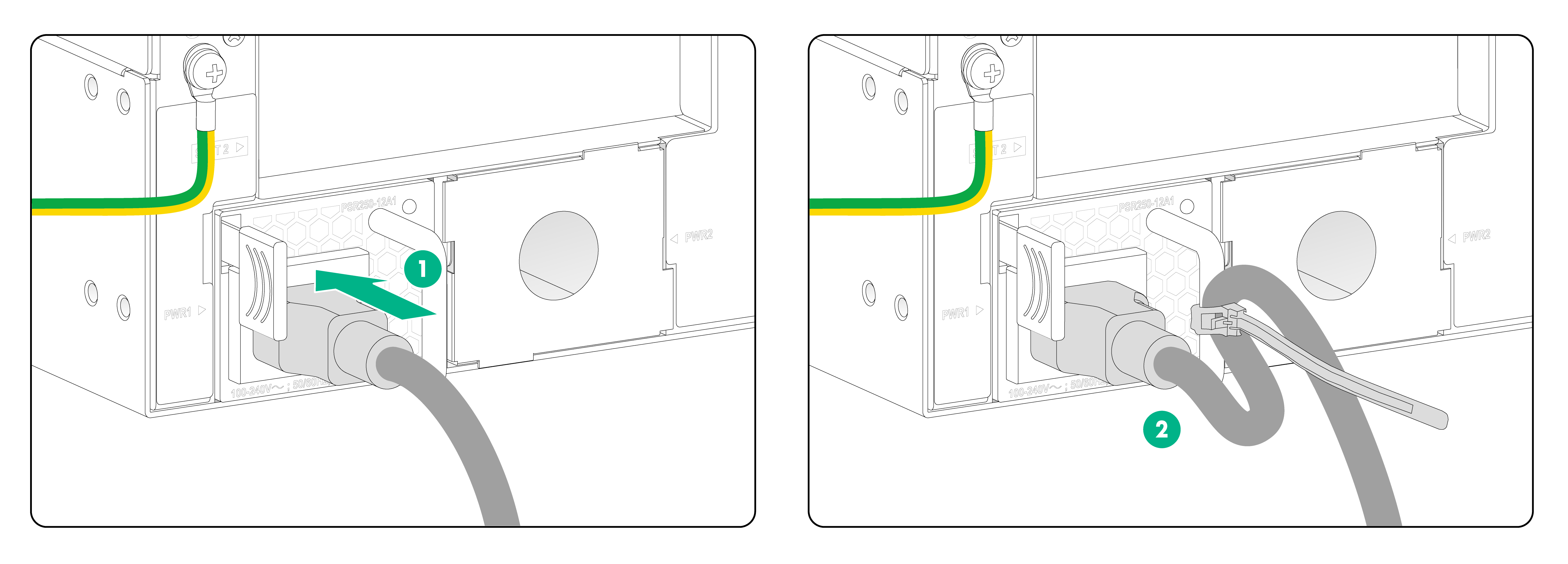
Connecting an AC power cord
1. Wear an ESD wrist strap. Make sure the wrist strap makes good skin contact and is reliably grounded.
2. Insert the female connector of the power cord into the AC power receptacle on the power supply.
3. Use a cable tie to secure the power cord to the handle of the power supply.
4. Connect the other end of the power cord to an AC power source.
Figure6-1 Connecting an AC power cord
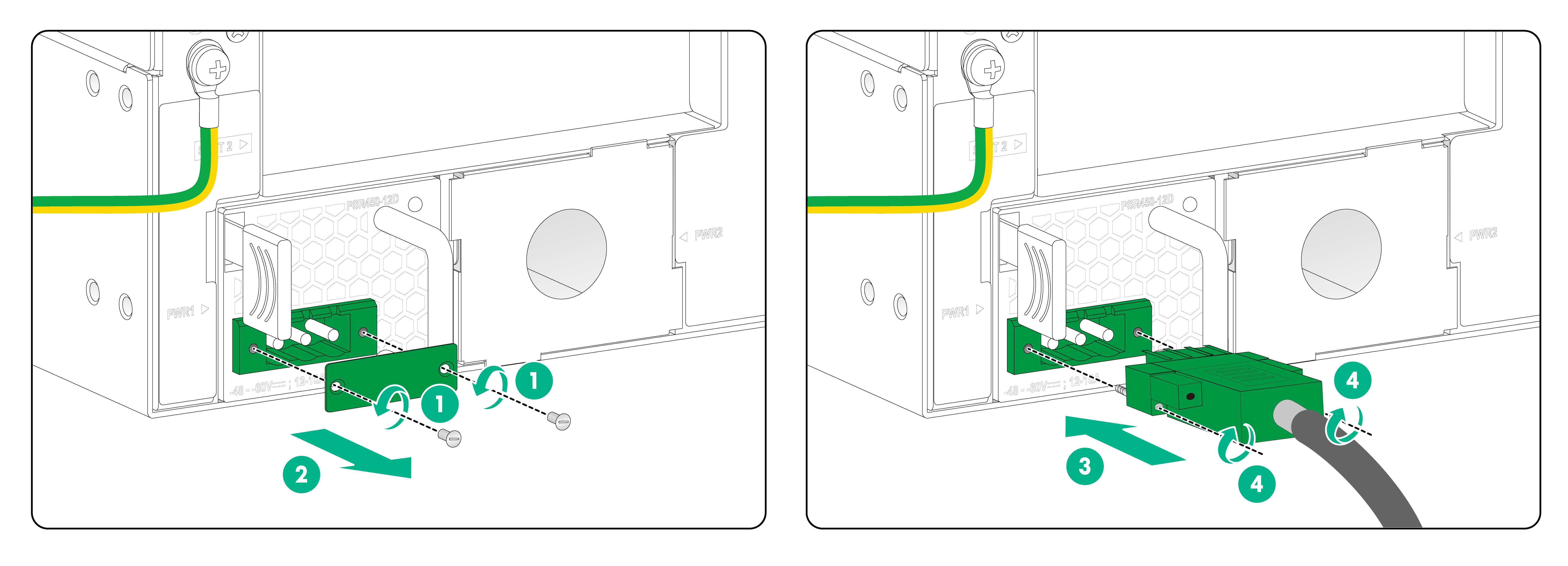
Connecting a DC power cord
1. Wear an ESD wrist strap. Make sure the wrist strap makes good skin contact and is reliably grounded.
2. Use a flat-head screwdriver to loosen the screws on the protective plate over the DC power receptacle and then remove the plate.
3. Correctly orient the DC power cord connector and insert it into the power receptacle.
The DC power cord connector and DC power receptacle form an anti-misinsertion structure. If you orient the DC power cord connector upside down, you cannot insert it into the receptacle.
4. Use a flat-head screwdriver to fasten the screws on the power cord connector to secure the connector to the power receptacle.
5. Connect the other end of the DC power cord to the wiring terminals of a DC power source, with the negative wire (–) to the negative terminal (–) and the positive wire (+) to the positive terminal (+).
Figure6-2 Connecting a DC power cord
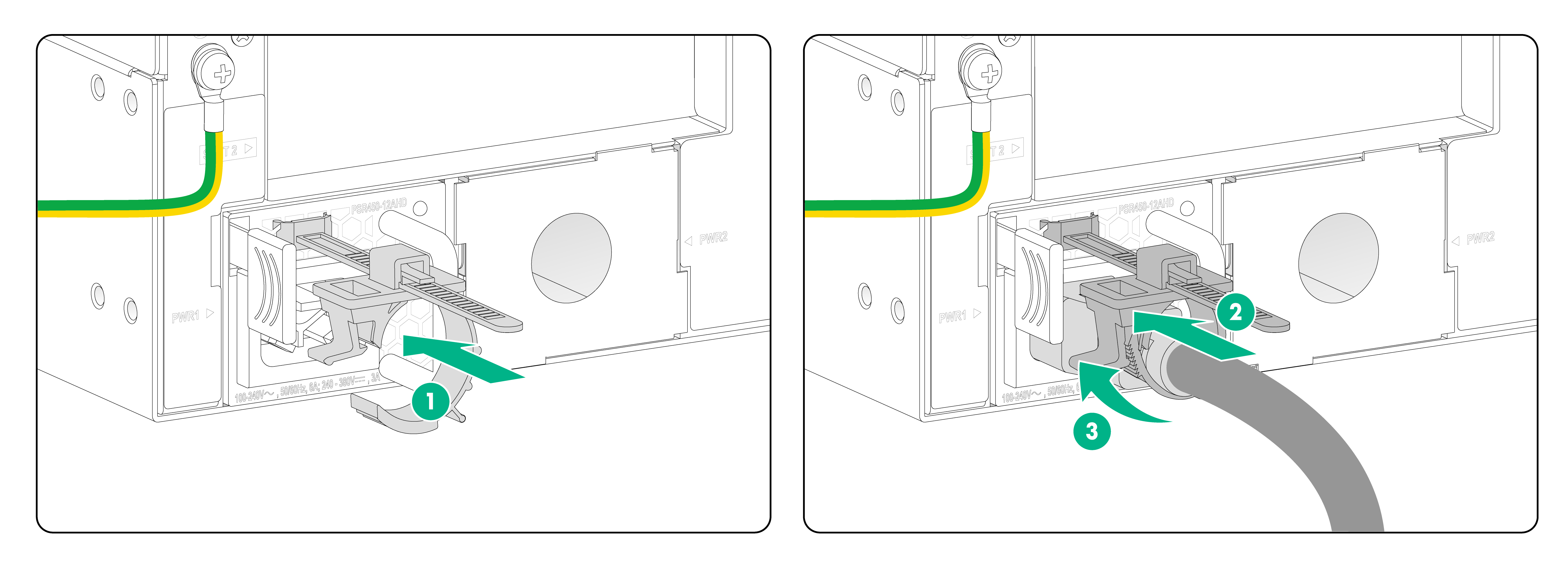
Connecting a high voltage DC power cord
1. Wear an ESD wrist strap. Make sure the wrist strap makes good skin contact and is reliably grounded.
2. Slide the cable clamp onto the tie mount on the power supply.
3. Connect the female connector of the power cord to the power receptacle on the power supply.
4. Close the cable clamp and slide it forward until it is flush against the edge of the female connector.
5. Connect the other end of the power cord to an AC or high-voltage DC power source.
Figure6-3 Connecting a high voltage DC power cord
7 Connecting Ethernet cables
Connecting copper Ethernet cables
Auto-MDI/MDIX is supported on the Ethernet copper ports on the front panel of the device and the 10/100/1000BASE-T ports on the interface cards. You can use straight-through or cross-over network cables to connect the copper Ethernet ports.
To connect a copper Ethernet cable:
1. Connect one end of the Ethernet cable to a copper Ethernet port on the device, and the other end of the cable to the peer Ethernet port.
2. Examine the LED for the Ethernet port to verify that the port is operating correctly. For more information about the LEDs, see H3C SR6602-I[IE] AI Series ICT Converged Gateways Hardware Information and Specifications.
|
|
NOTE: After connecting the device to the network, you can use the ping or tracert command to verify network connectivity of the device. For more information about the commands, see the command references for the device. |
Connecting optical fibers
|
|
WARNING! Disconnected optical fibers or transceiver modules might emit invisible laser light. Do not stare into beams or view directly with optical instruments when the device is operating. |
|
|
CAUTION: · Never bend an optical fiber excessively. The bend radius of an optical fiber must be not less than 100 mm (3.94 in). · Keep the fiber end clean. · To connect an optical fiber to a fiber port, make sure the fiber connector matches the transceiver module. · Before connecting an optical fiber, make sure the received optical power does not exceed the upper receive power threshold of the transceiver module. If the threshold is exceeded, the transceiver module might be damaged. · To connect an optical fiber to a fiber port, first install a transceiver module in the fiber port and then connect the optical fiber to the transceiver module. · Insert a dust plug into any open fiber port. |
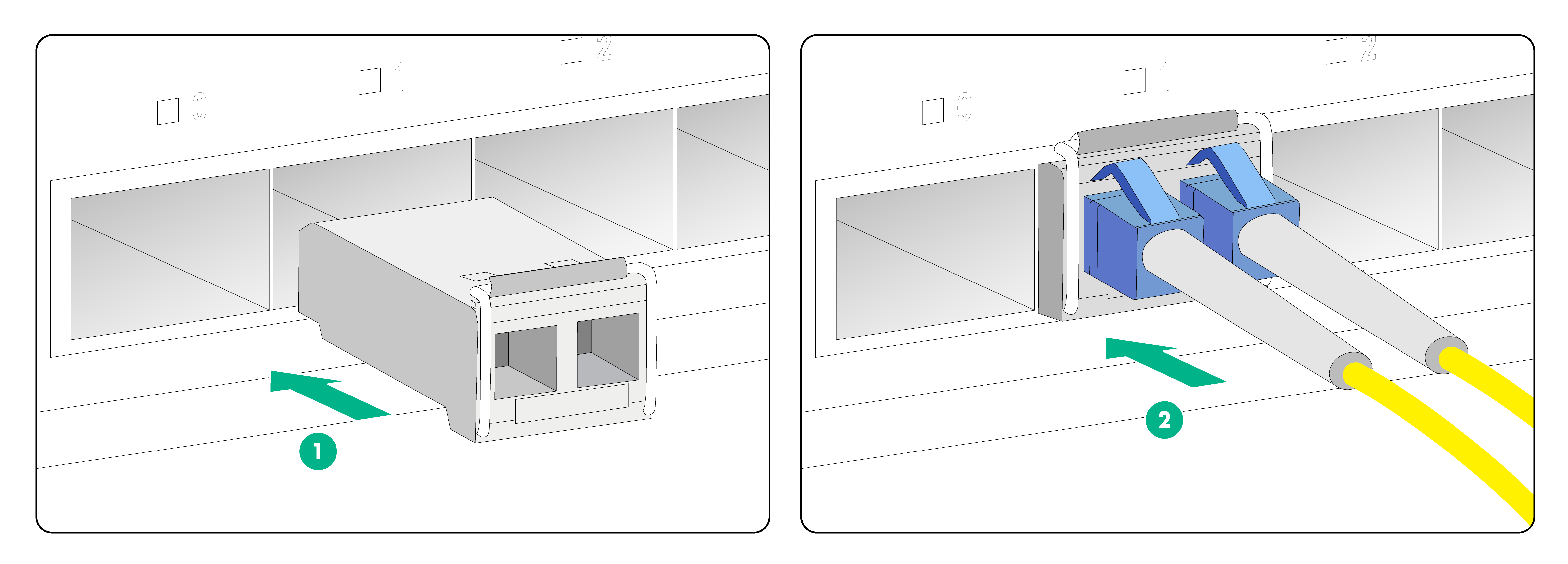
To connect an optical fiber:
1. Remove the dust plug from the fiber port.
2. Pivot the clasp of the transceiver module up to catch the clip on the top. Hold the two sides of the transceiver module and insert it slowly into the fiber port.
3. Remove the dust cap from the optical fiber connector, and use dust-free paper and absolute ethanol to clean the end face of the fiber connector.
4. Identify the Rx and Tx ports on the transceiver module. Use the optical fiber to connect the Rx port and the Tx port on the transceiver module to the Tx port and the Rx port on the peer device, respectively.
Figure7-1 Connecting a transceiver module and optical fiber
Connecting E1 interface cables
The MIC-X-ET16 interface card provides E1 ports. To connect an E1 port by using an E1 interface cable, see the interface card manual.
8 Verifying the installation
After the installation is completed, verify the following items:
· There is enough space around the device for heat dissipation.
· The rack or workbench is stable.
· The grounding cable is correctly and securely connected.
· The power supplies are compatible with the device, and the power source is as required by the device.
· The power cords are correctly connected.
· If part of the network cable for a port is routed outdoors, verify that a network port lightning protector is used for the port.
· If a power line is routed from outdoors, verify that a surge protected power strip is used for the device.
9 Accessing the device for the first time
To access the device for the first time, use a serial console cable to connect a console terminal (for example, a PC) to the serial console port on the device.
Connecting the device to a configuration terminal
A serial console cable is an 8-core shielded copper cable, with a crimped RJ-45 connector at one end for connecting to the serial console port on the device, and a DB-9 female connector at the other end for connecting to the serial port on the configuration terminal.
Figure9-1 Serial console cable

Table9-1 Serial console cable pinout
|
RJ-45 |
Signal |
DB-9 |
Signal |
|
1 |
RTS |
8 |
CTS |
|
2 |
DTR |
6 |
DSR |
|
3 |
TXD |
2 |
RXD |
|
4 |
SG |
5 |
SG |
|
5 |
SG |
5 |
SG |
|
6 |
RXD |
3 |
TXD |
|
7 |
DSR |
4 |
DTR |
|
8 |
CTS |
7 |
RTS |
|
|
CAUTION: · Identify the mark for the console port and make sure you are connecting to the correct port. · The serial ports on PCs do not support hot swapping. If the device has been powered on, connect the serial console cable to the PC before connecting to the device, and when you disconnect the cable, first disconnect from the device. |
To connect the device to a configuration terminal by using a serial console cable:
1. Connect the DB-9 female connector of the serial console cable to the serial port on the configuration terminal.
2. Connect the RJ-45 connector to the serial console port on the device.
Setting terminal parameters
To configure and manage the device through the console port, you must run a terminal emulator program, HyperTerminal or PuTTY, on your configuration terminal. You can use the emulator program to connect a network device, a Telnet site, or an SSH site. For more information about the terminal emulator programs, see the user guides for these programs
Configure the terminal parameters as follows:
· Bits per second—9600.
· Data bits—8.
· Stop bits—1.
· Parity—None.
· Flow control—None.
Starting the device
1. Verify that the following conditions are met before powering on the device:
¡ The power cord is correctly connected.
¡ The input power voltage is as required by the device.
¡ The console cable is correctly connected.
¡ The configuration terminal (a PC, for example) has started, and terminal parameters have been configured correctly.
2. Power on the device.
During the startup process, you can access Boot ROM menus to perform tasks such as software upgrade and file management. The Boot ROM interface and menu options vary by software version. For more information about Boot ROM menu options, see the release notes for the specific software version.
3. Examine the LEDs on the device to verify that the device is operating correctly. If the RUN LED is flashing green at 1 Hz, the device is operating correctly. For more information about the LEDs, see H3C SR6602-I[IE] AI Series ICT Converged Gateways Hardware Information and Specifications.
4. Access the CLI to configure the device.
For more information about the configuration commands, see the configuration guides and command references for the device.
10 Maintaining the device
Replacing a power supply
|
|
WARNING! To avoid device damage or bodily injury, strictly follow the removal procedure in Figure10-1 to remove a power supply. |
Figure10-1 Power supply removal procedure
![]()
|
|
CAUTION: For adequate heat dissipation and dust prevention, install a filler panel in a power supply slot if you are not to install a new power supply in the slot after removing the old one. |
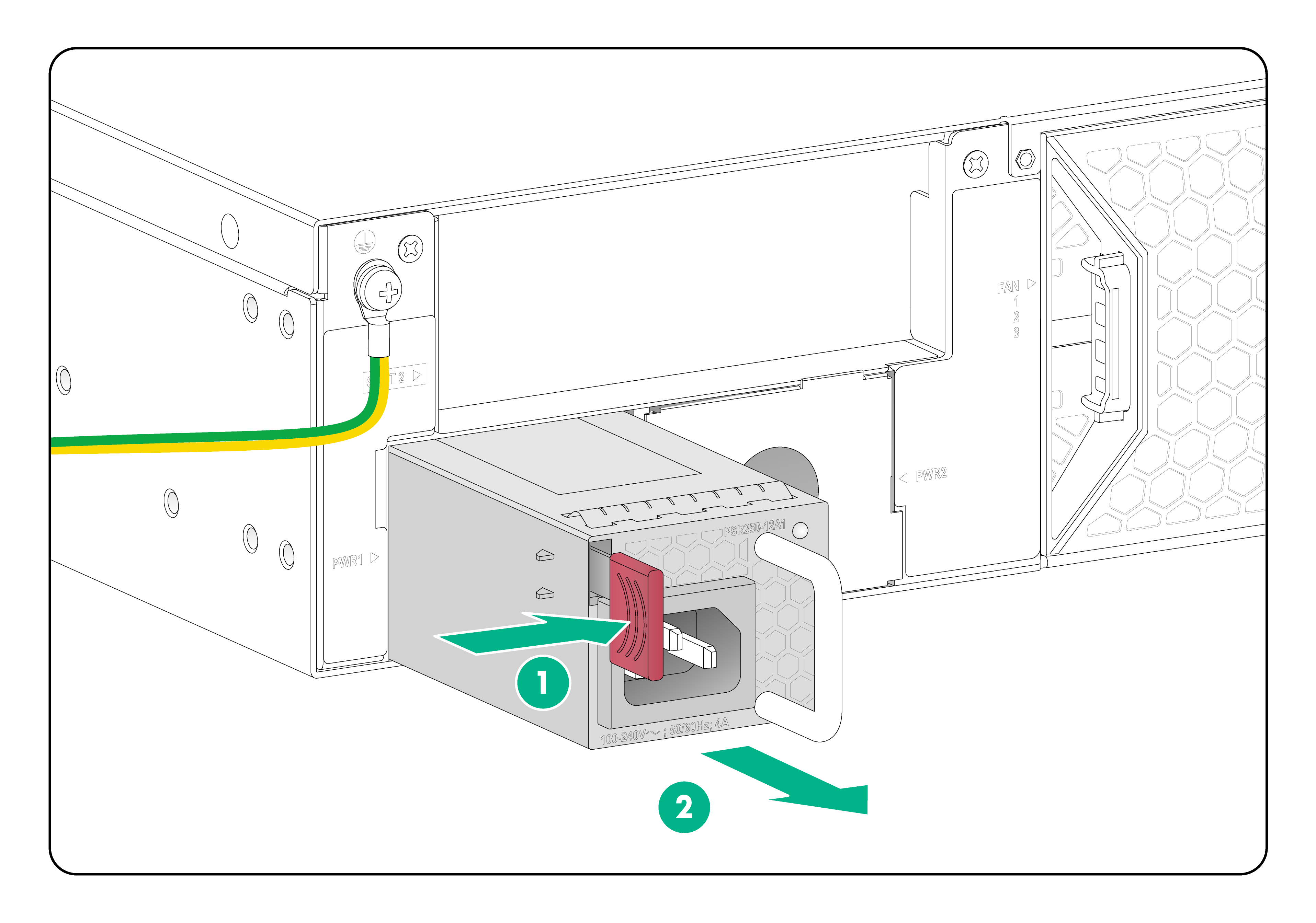
1. Wear an ESD wrist strap. Make sure the wrist strap makes good skin contact and is reliably grounded.
2. Remove the power cord from the power supply.
3. Pressing the latch on the power supply towards the handle direction, pull the power supply slowly out of the slot, as shown in Figure10-2.
4. Place the removed power supply on an antistatic mat.
5. Install a new power supply in the slot. For the installation procedure, see "Installing power supplies."
If you are no to install a new power supply, install a filler panel in the slot.
Figure10-2 Removing a power supply
Replacing a fan tray
|
|
WARNING! · Ensure electricity safety when replacing a fan tray during device operation. · To avoid injury, do not touch the rotating fan blades. |
|
|
CAUTION: · To avoid disturbing the dynamic balance of a fan tray and causing loud noises, do not touch the fan blades and rotation axis even if the fan tray stops rotating. · When a fan tray fails during device operation, replace the fan tray immediately. Keep the failed fan tray in position until you start the replacement. · When an internal circuit or component of a fan tray is faulty, contact H3C Support for repair. Do not remove the components yourself. |
The device has three fan tray slots. Slot FAN3 is reserved for future use. As a best practice, install a fan tray in both the FAN1 and FAN2 slots. When two fan trays are installed on the device, you can hot swap one of them.
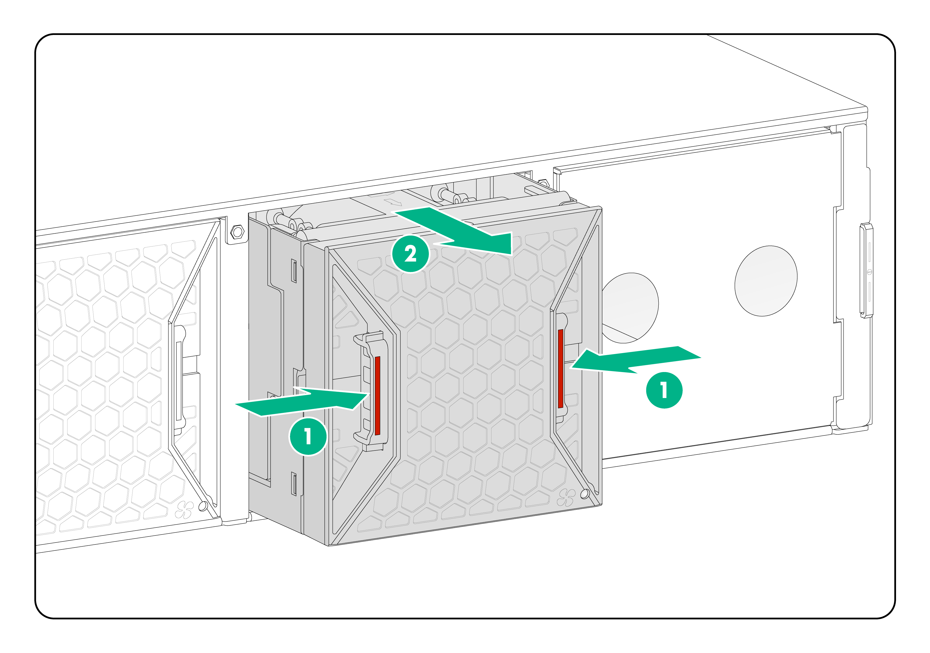
To replace a fan tray:
1. Wear an ESD wrist strap. Make sure it makes good skin contact and is reliably grounded.
2. As shown in Figure10-3, pressing the two release buttons on the fan tray, pull the fan tray slowly out of the slot. Place the removed fan tray on an antistatic mat.
Figure10-3 Removing a fan tray
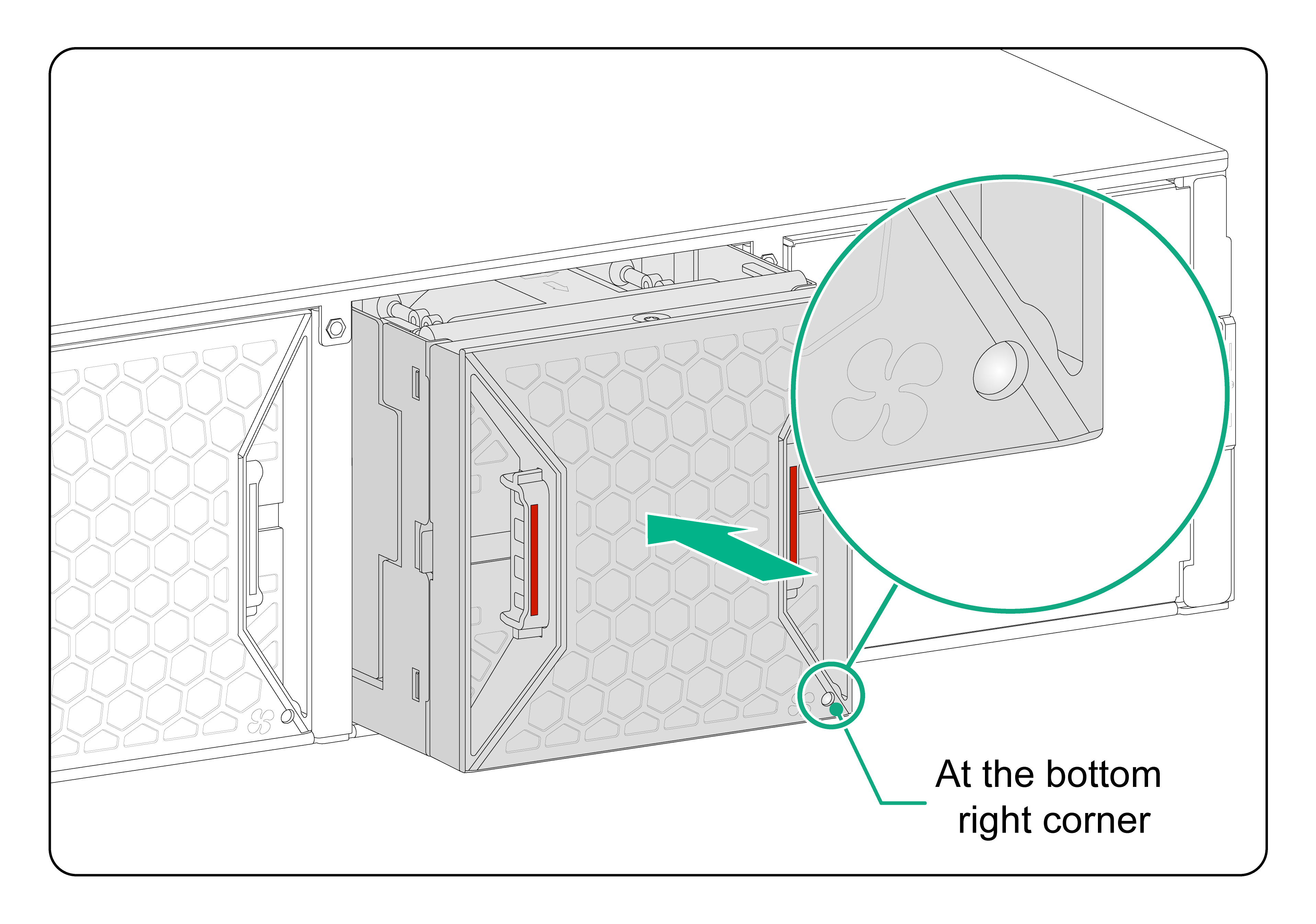
3. Install a new fan tray.
Insert the fan tray slowly into the slot along the guide rails until the fan tray is fully inserted into the slot and makes good contact with the device connectors.
The fan tray and fan tray slot form an anti-misinsertion structure. If the fan tray is oriented incorrectly, you cannot insert it into the slot.
Figure10-4 Installing a fan tray
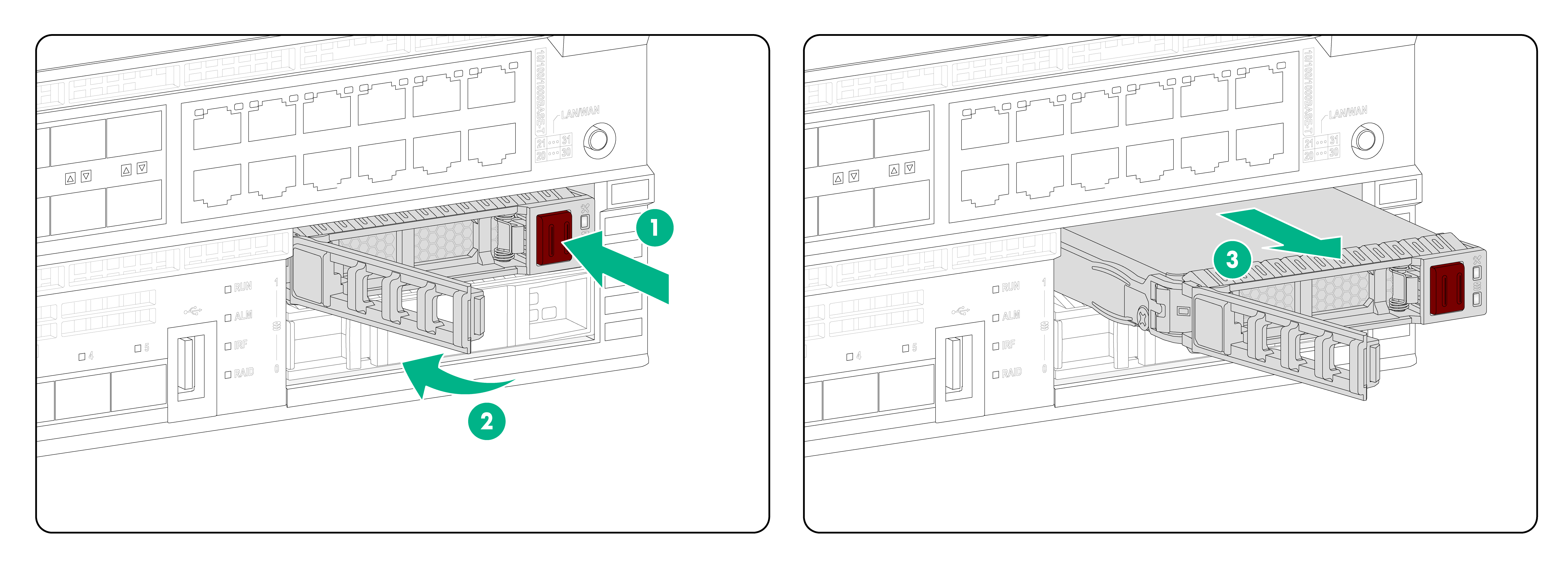
Replacing a FIP module
|
|
CAUTION: · Do not touch the components on a FIP module directly with your hands. · Do not use excessive force during the replacement procedure. · For adequate heat dissipation and dust prevention, install a filler panel in a FIP module slot if you are not to install a new FIP module in the slot after removing the old one. |
To remove a FIP module during device operation, first press the remove button for over 0.5 seconds. You can remove the FIP module only after the remove LED is off.
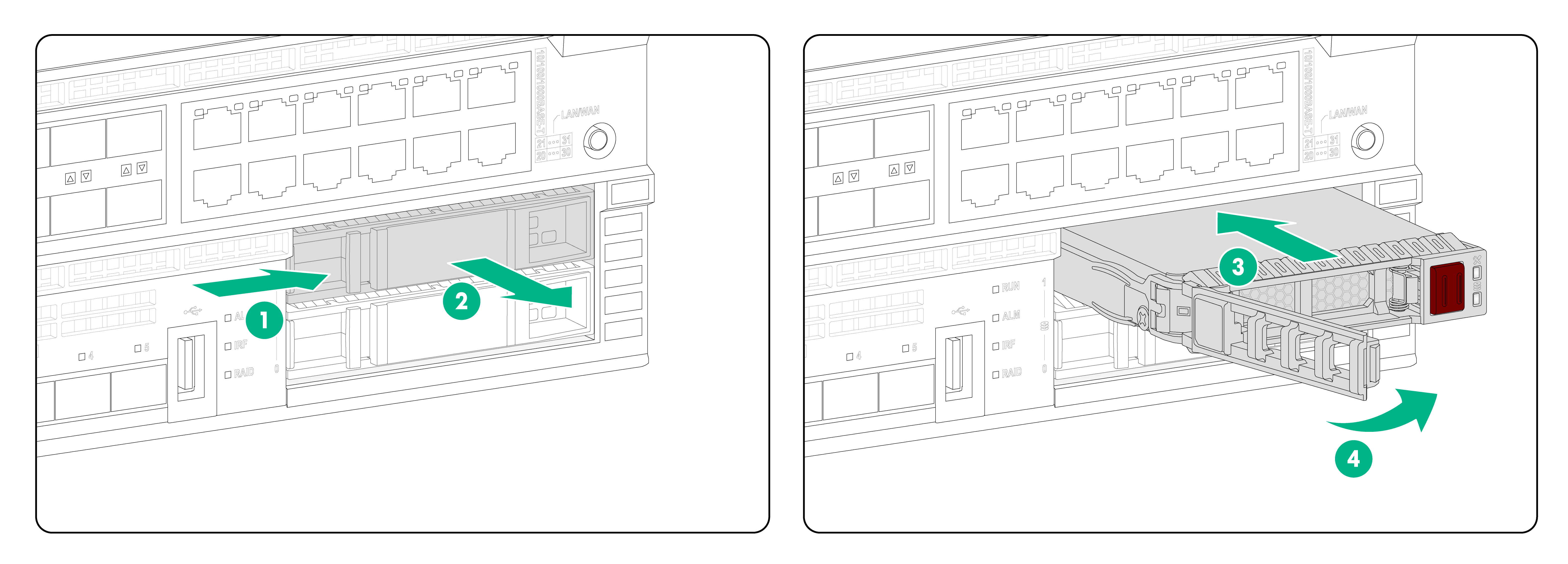
To remove a FIP module:
1. Wear an ESD wrist strap. Make sure the wrist strap makes good skin contact and is reliably grounded.
2. Remove all cables from the module.
3. As shown in Figure10-5, holding the ejector lever of the FIP module with one hand and pressing down the red latch on the ejector lever, pull the FIP module part way out of the slot. Supporting the FIP module bottom with the other, pull the module completely out of the slot.
4. Place the removed FIP module on an antistatic mat.
5. Install a new FIP module. For the installation procedure, see "Installing a FIP module."
If you are not to install a new FIP module, install a filler panel in the slot.
Figure10-5 Removing a FIP module
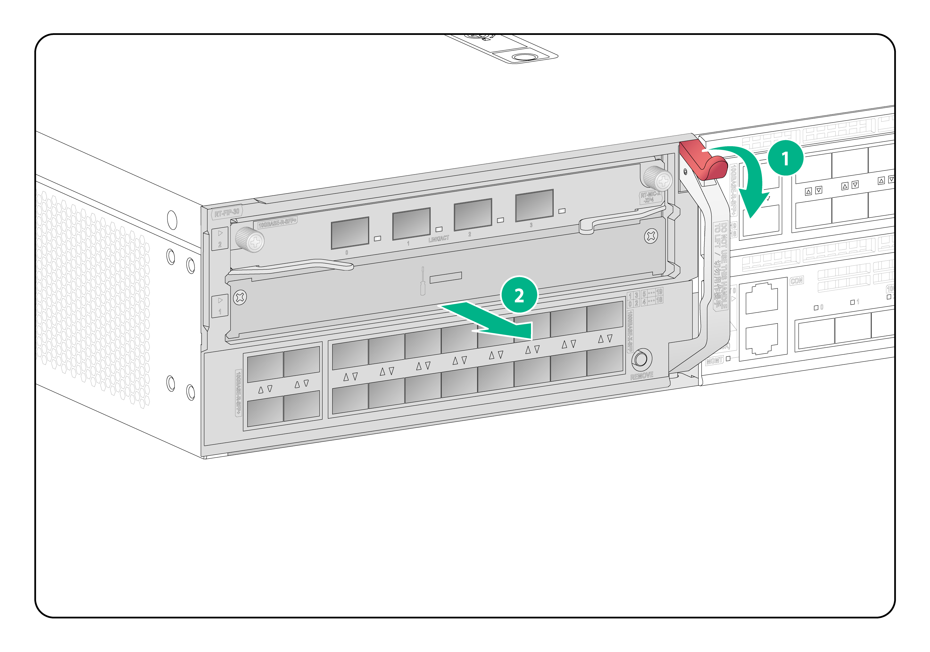
Replacing a MIC-X interface card
|
|
CAUTION: You cannot install but can remove a MIC-X interface card when the device is operating. |
To replace a MIC-X interface card:
1. Verify that the FIP module is operating correctly.
The remove LED on the FIP module is steady green when the FIP module is operating correctly. You can also use the display device verbose command to view the FIP module operating status.
2. Wear an ESD wrist strap. Make sure the wrist strap makes good skin contact and is reliably grounded.
3. Use a Phillips screwdriver to loosen the captive screws on the module.
4. Open the two ejector levers of the interface card simultaneously.
5. Pull the interface card slowly out of the slot along the guide rails.
6. Place the removed interface card on an antistatic mat.
7. Install a new MIC-X interface card.
|
|
CAUTION: To install a new MIC-X interface card, first remove the FIP module from the device. For the installation procedure, see "Installing MIC-X interface cards." |
If you are not to install a new MIC-X interface card, install a filler panel in the slot.
Figure10-6 Removing a MIC-X interface card

Replacing a SATA drive
|
|
CAUTION: The SATA drives are hot swappable. You can install a SATA drive, or remove a SATA drive in RAID configuration as indicated by the LED without powering off the device. To remove a SATA drive not in RAID configuration, you must first power off the device. |
To replace a SATA drive:
1. Press the red button on the drive tray panel to release the locking lever.
2. Hold the locking lever and pull the drive out of the slot.
3. Place the removed SATA drive on an antistatic mat.
4. Install a new SATA drive. For the installation procedure, see "Installing SATA drives."
If you are not to install a new SATA drive, install a filler panel in the slot.
Figure10-7 Removing a SATA drive
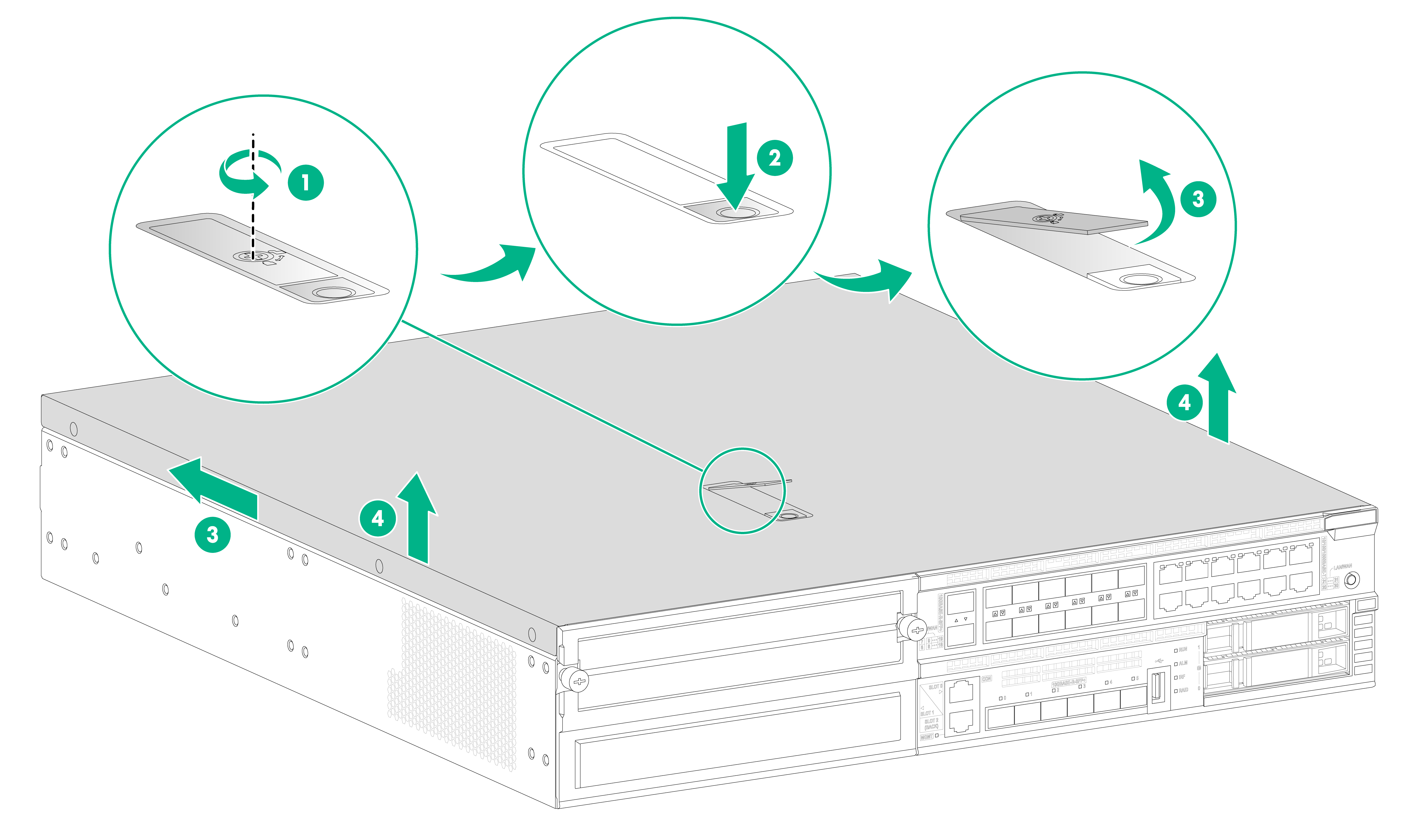
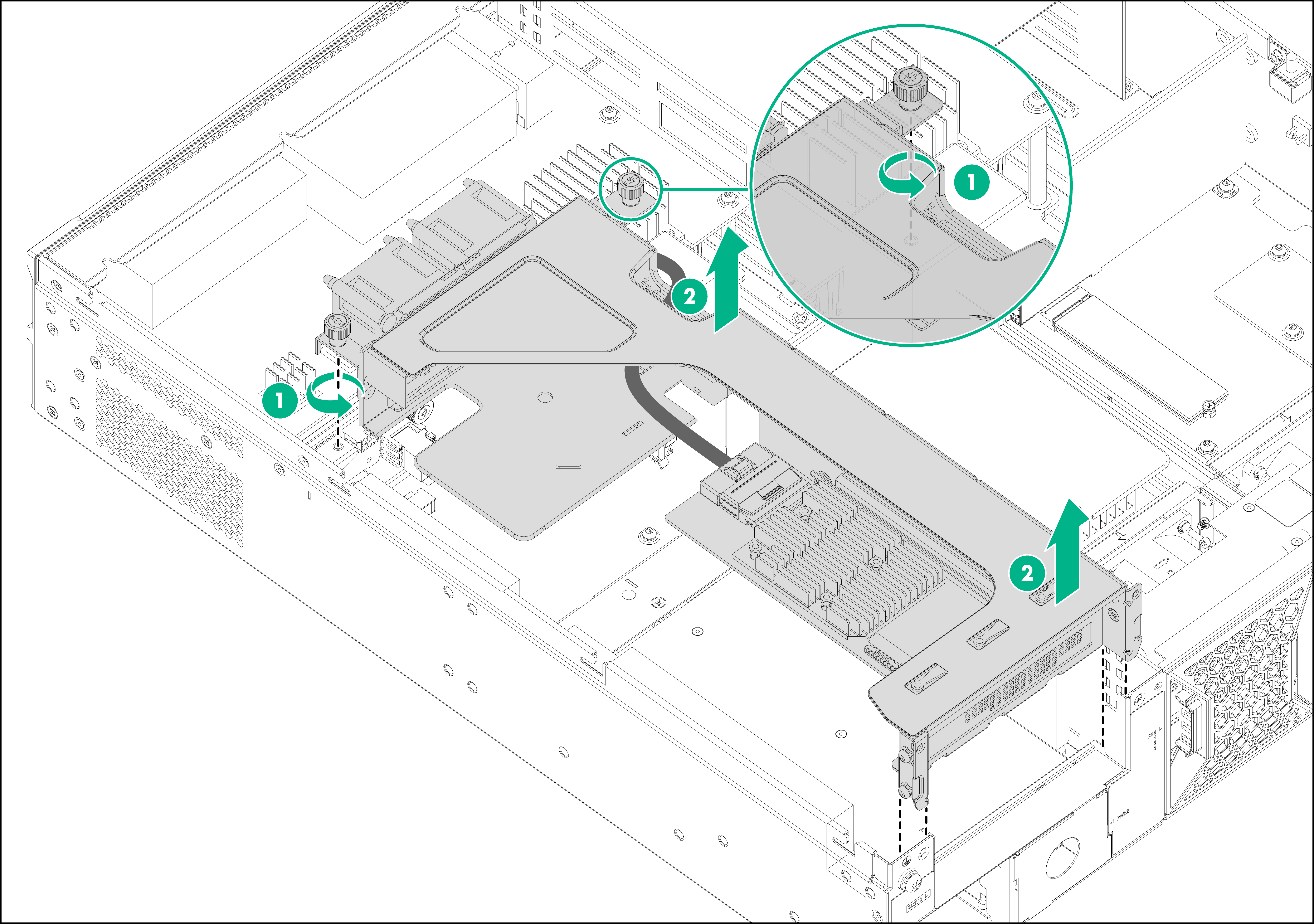
Replacing a storage controller
1. Power off the device.
2. Remove the access panel.
a. Facing the front panel of the device, use a Phillips screwdriver to turn the screw on the locking lever anticlockwise to unlock the lever.
b. Press the blue button on the locking lever and then pull the locking lever backward. The access panel will automatically slide to the rear of the chassis.
c. Hold the access panel by its sides and lift it from the chassis.
Figure10-8 Removing the access panel
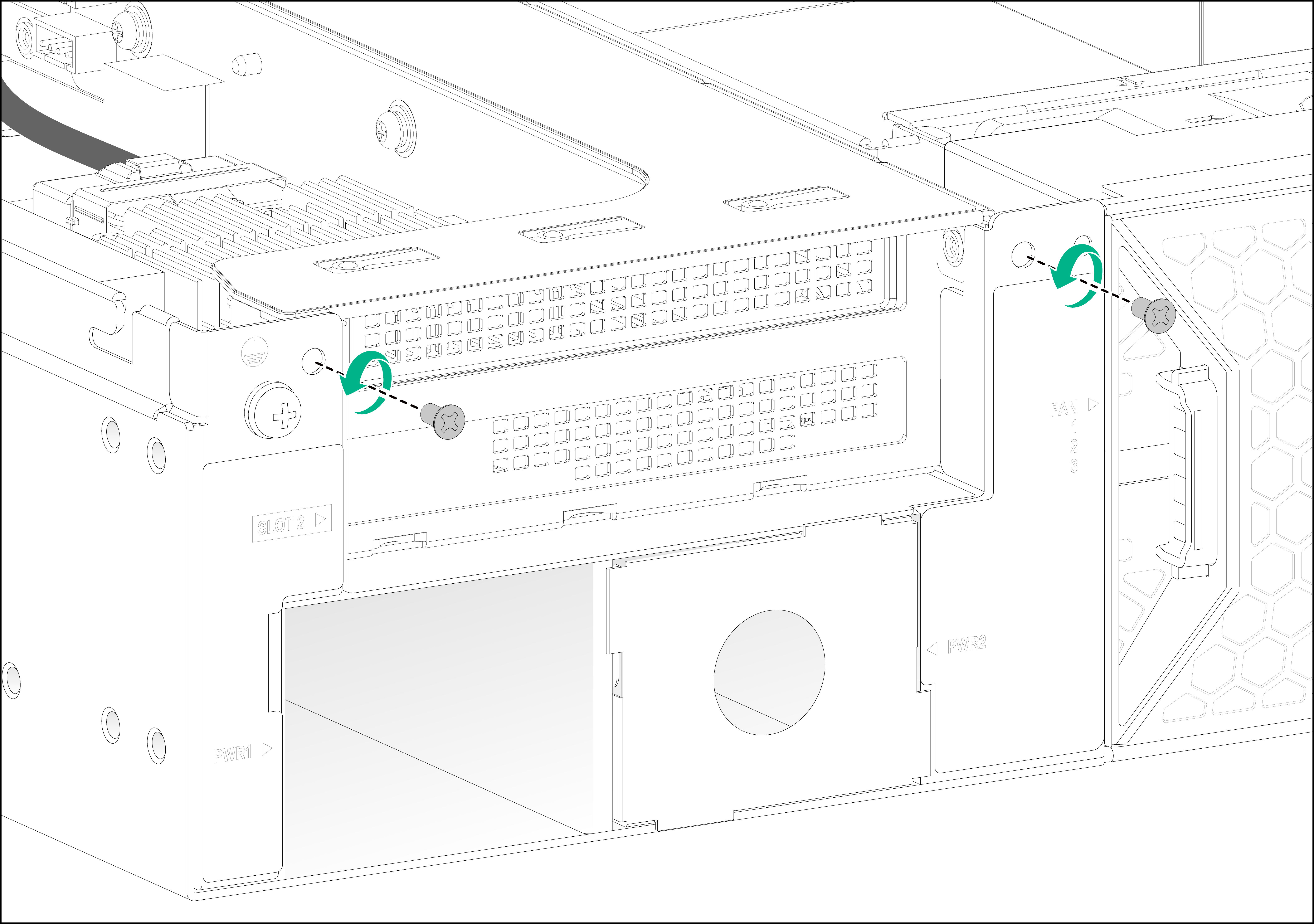
3. Use a Phillips screwdriver to remove the screws that secure the riser module to the chassis.
Figure10-9 Removing the screws that secure the riser module to the chassis
4. Loosen the captive screws on the riser module and lift the riser module slowly out of the chassis and remove the cables from the riser module.
Figure10-10 Removing the riser module
5. Place the removed riser module on an antistatic mat.
6. Use a Phillips screwdriver to remove the screws that secure the storage controller to the riser module. Then remove the storage controller from the PCIe slot of the riser module.
Figure10-11 Removing the storage controller from the riser module
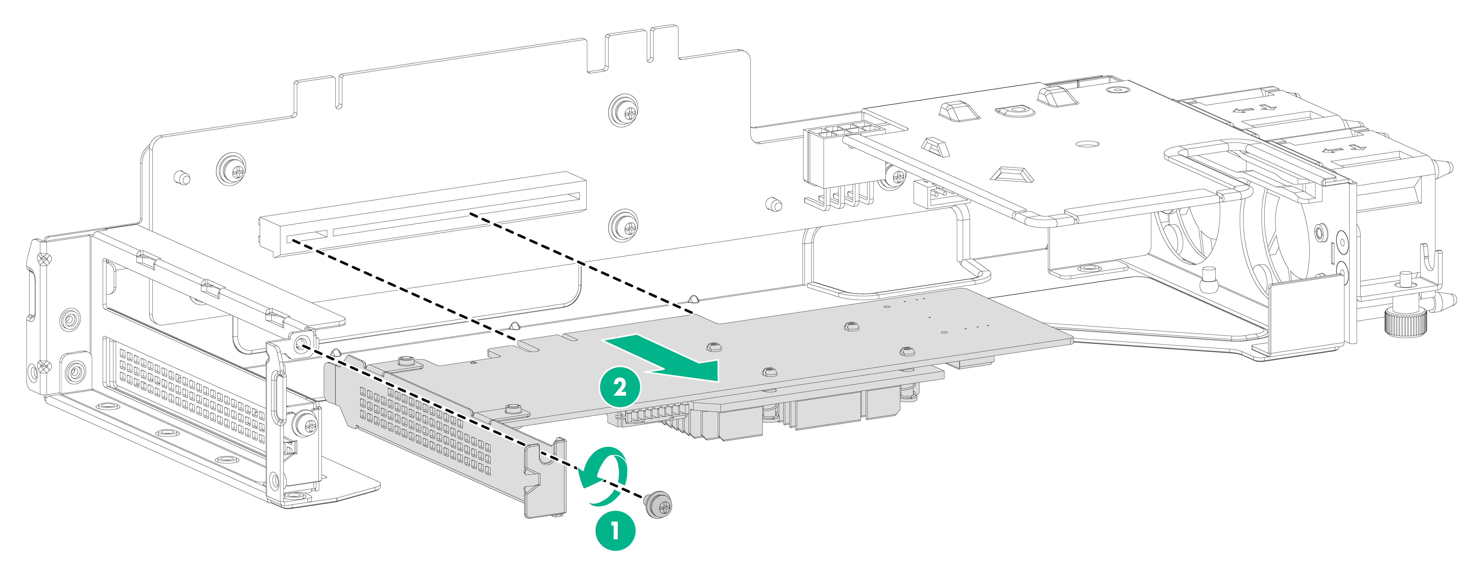
7. Place the removed storage controller on an antistatic mat.
8. Install a new storage controller in the PCIe slot on the riser module. For the installation procedure, see "Installing a storage controller."
If you are not to install a new storage controller, connect the drive backplane cable. Then install a module blank in the PCIe slot on the riser module and reinstall the access panel.
Figure10-12 Connecting the drive backplane cable
Replacing a GPU
1. Power off the device.
2. Remove the access panel. For more information, see "Replacing a storage controller."
3. Use a Phillips screwdriver to loosen the screws that secure the riser module to the chassis. For more information, see "Replacing a storage controller."
4. Remove the riser module. For more information, see "Replacing a storage controller."
5. Place the removed riser module on an antistatic mat.
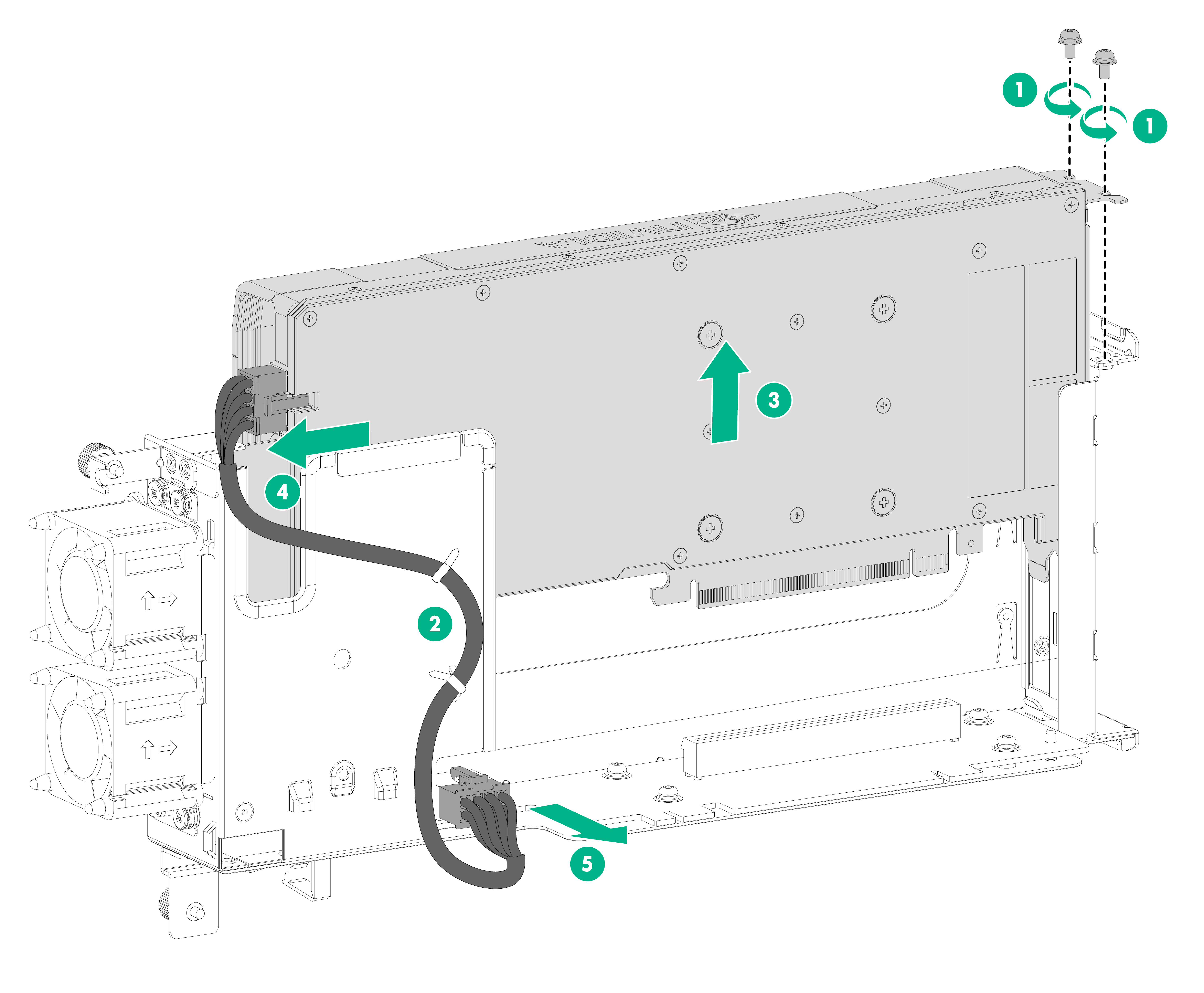
6. Remove the GPU from the riser module.
a. Use a Phillips screwdriver to remove the two screws that secure the GPU to the riser module.
b. Remove the cable ties from the riser module. Avoid damaging the GPU power cords during the cable tie removal procedure.
c. Pull the GPU slowly out of the PCIe slot and remove the power cords from the GPU.
Figure10-13 Removing the GPU
7. Remove the support bracket from the GPU.
Figure10-14 Removing the GPU support bracket
8. Put the removed GPU bracket on an antistatic mat.
9. Install a new GPU in the PCIe slot on the riser module. For the installation procedure, see "Installing a GPU."
If you are not to install a new GPU, install a module blank in the PCIe slot and then reinstall the access panel.
Replacing an M.2 SSD
1. Power off the device.
2. Remove the access panel. For more information, see "Replacing a storage controller."
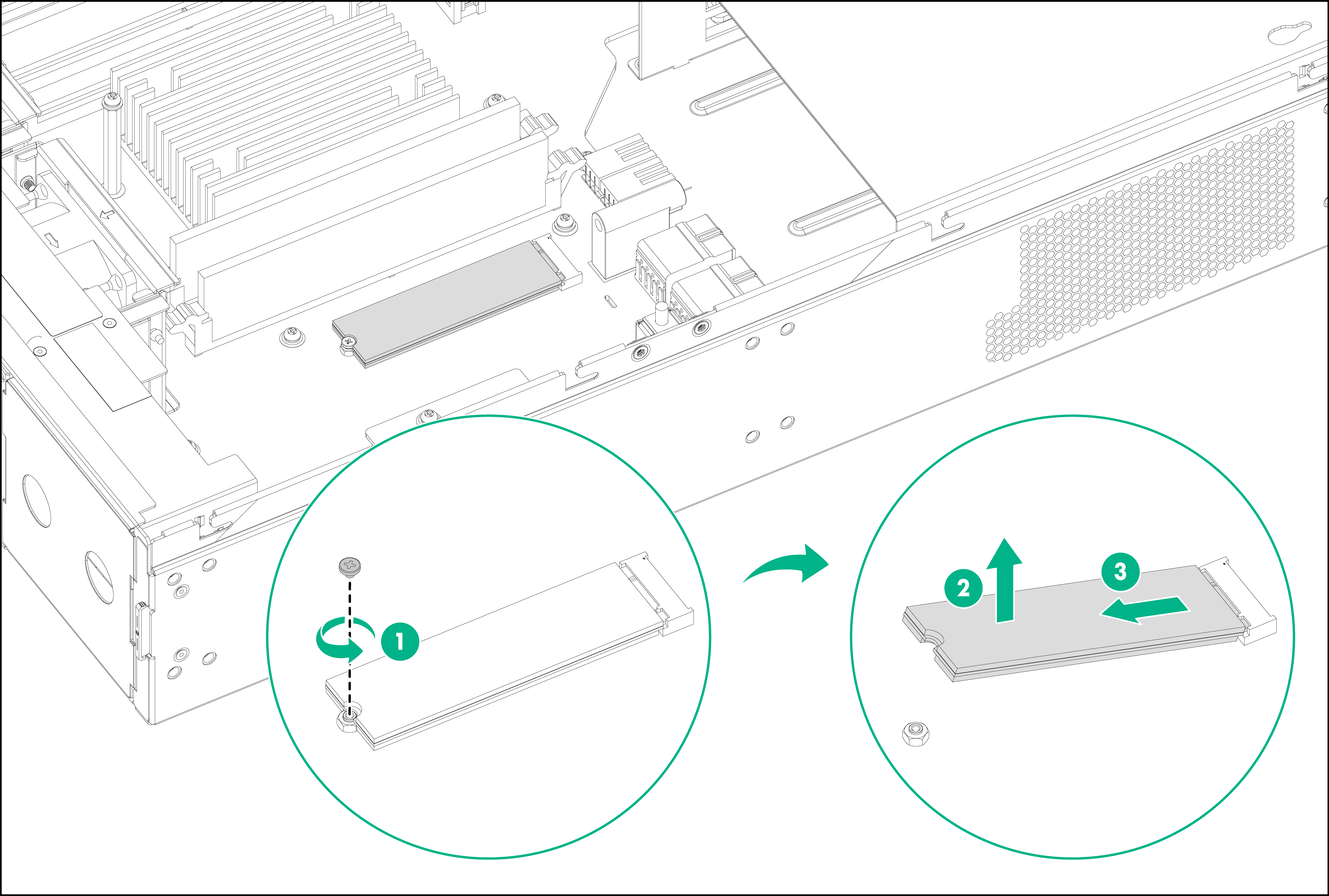
3. Use a Phillips screwdriver to remove the screw that secures the M.2 SSD on the chassis.
4. Pull the SSD out of the connector and keep the SSD secure for future use.
Figure10-15 Removing an M.2 SSD drive
5. Install a new M.2 SSD. For the installation procedure, see "Installing an M.2 SSD drive."
If you are not to install a new M.2 SSD, insert the M.2 SSD screw into the screw hole and then reinstall the access panel.
Replacing a DIMM
1. Power off the device.
2. Remove the access panel. For more information, see "Replacing a storage controller."
3. Open the DIMM slot latches and pull the DIMM out of the slot
Figure10-16 Removing a DIMM
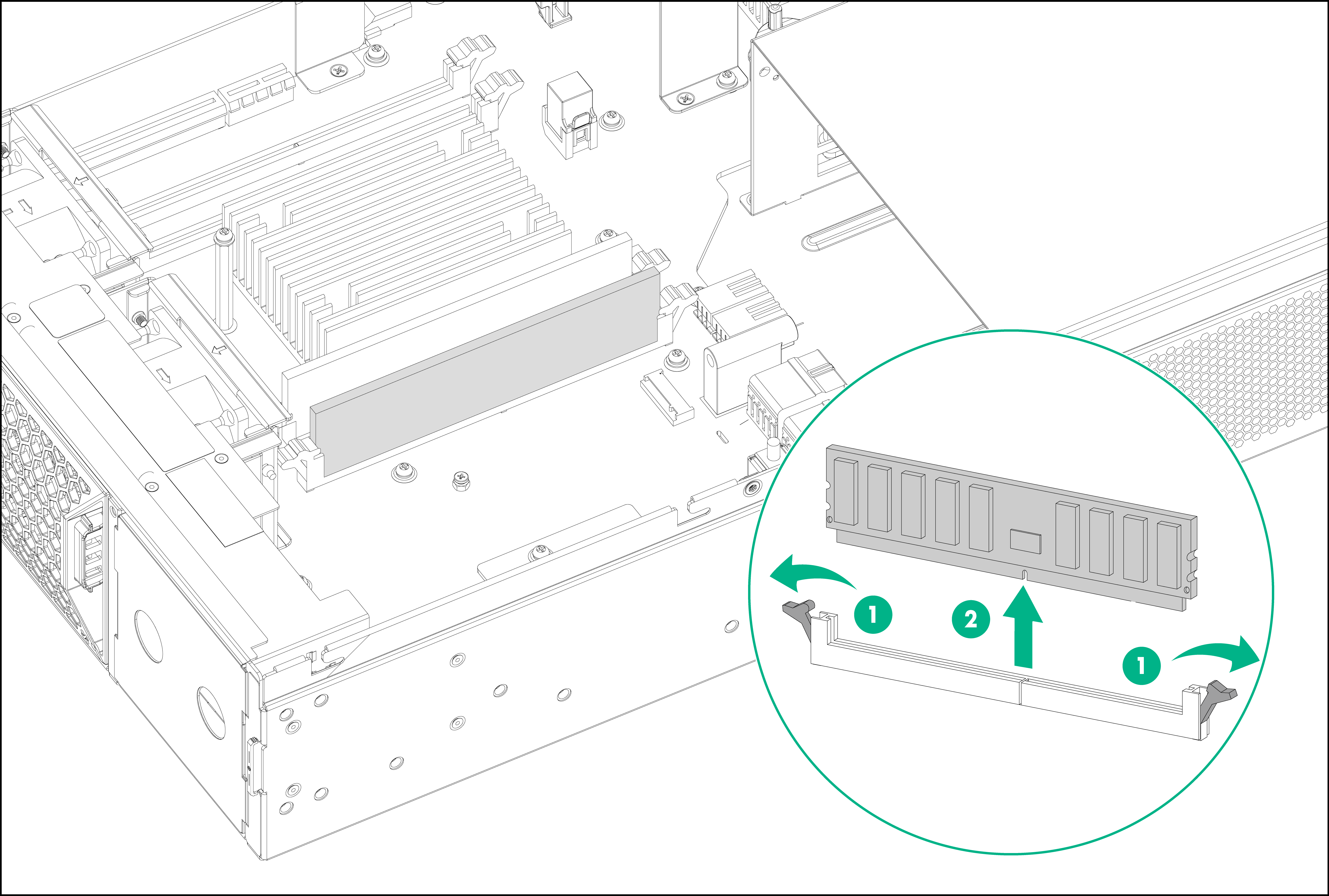
4. Place the removed DIMM on an antistatic mat.
5. Install a new DIMM. For the installation procedure, see "Installing a DIMM."
If you are not to install a new DIMM, reinstall the access panel.
11 Hardware management and maintenance
The command lines and outputs vary by software version. For more information about the command lines and their outputs, see the command references for the specific software version.
Displaying software and hardware version information for the device
Use the display version command to display software and hardware version information for the device. This command also displays the system running time and the type and running time of each module.
<Sysname> display version
Displaying device operating information
During daily maintenance or when a fault occurs, you need to view the running information of each functional module to locate the issue.
You can use one of the following methods to collect operating statistics for diagnostics and troubleshooting:
· Use separate display commands, such as display clock, display version, display device, and display current-configuration to collect operating information feature by feature or module by module.
· Use the display diagnostic-information command to save or display operating information for multiple or all features and hardware modules.
¡ Save operating information for multiple or all features and hardware modules:
<Sysname> display diagnostic-information
Save or display diagnostic information (Y=save, N=display)? [Y/N]:y
Please input the file name(*.tar.gz)[sda0:/diag_SR6602-I_20200818-174021.tar.gz]: diag.tar.gz
Diagnostic information is outputting to sda0:/diag.tar.gz.
Please wait...
Save successfully.
To save storage space, this command automatically compresses the information before saving the information to a file. To view the file content:
# Use the tar extract archive-file command to extract the file.
# Use the gunzip command to decompress the extracted file.
# Use the more command to view the content of the decompressed file.
¡ Save operating information for multiple or all features and hardware modules:
<Sysname> display diagnostic-information
Save or display diagnostic information (Y=save, N=display)? [Y/N]:n
===============================================
===============display clock===============
14:03:55 UTC Thu 01/05/2020
=================================================
===============display version===============
…
Displaying detailed device information
Use the display device verbose command to display detailed information about the device and the modules.
<Sysname> display device verbose
Slot No. Board type Status Primary SubSlots
--------------------------------------------------------------
0 RT-SR6602-IE Normal Master 0
1 RT-FIP-30 Normal N/A 2
2 N/A Absent N/A N/A
Slot 0: RT-SR6602-IE
Subslot No. Board Type Status Max Ports
--------------------------------------------------------------
0 Fixed SubCard on Board Normal 34
Slot 1: RT-FIP-30
Subslot No. Board Type Status Max Ports
--------------------------------------------------------------
0 Fixed SubCard on Board Normal 20
Slot 0: RT-SR6602-IE
Subslot 0
Status: Normal
Type: Fixed SubCard on Board
Hardware: Ver.B
Driver: 1.0
CPLD: 1.0
FPGA: 208.0
Slot 1: RT-FIP-30
Subslot 0
Status: Normal
Type: Fixed SubCard on Board
Hardware: Ver.A
Driver: 1.0
CPLD: 1.0
FPGA: 308.0
Subslot 1
Status: Normal
Type: RT-MIC-X-ET16
Hardware: Ver.@
Driver: 1.0
CPLD: 1.0
Subslot 2
Status: Normal
Type: RT-MIC-X-CLP4
Hardware: Ver.A
Driver: 1.0
CPLD: 1.0
Use the display device slot slot-number command to display detailed information about a module.
<Sysname> display device slot 1
Slot 1: RT-FIP-30
Subslot No. Board Type Status Max Ports
--------------------------------------------------------------
0 Fixed SubCard on Board Normal 20
1 RT-MIC-X-ET16 Normal 16
2 RT-MIC-X-CLP4 Normal 4
Table11-1 Command output
|
Field |
Description |
|
Slot No |
Slot number. |
|
Board Type |
Hardware type of the module. |
|
Status |
Module status: · Absent—The slot is empty. · Fault—The module in the slot is faulty and cannot start up. · Normal—The module is operating correctly. |
|
Primary |
Role of the module. Master indicates that the module is an MPU. |
|
Max Ports |
Number of ports on the module. |
Displaying electrical label information for the device
Use the display device manuinfo command to display electrical label information for the device.
An electronic label contains the permanent configuration information, including the name, hardware serial number, manufacturing date, MAC address, and vendor name of the device and modules.
<Sysname> display device manuinfo
Chassis self:
The operation is not supported on the specified chassis.
Slot 0 CPU 0:
DEVICE_NAME:SR6602
DEVICE_SERIAL_NUMBER:210235A2G5X199000001
MAC_ADDRESS:000F-E212-3451
MANUFACTURING_DATE:2019-09-18
VENDOR_NAME:H3C
Slot 1:
DEVICE_NAME:RT-FIP-30
DEVICE_SERIAL_NUMBER:210231ADDL0000000011
MAC_ADDRESS:4422-8866-0000
MANUFACTURING_DATE:2020-06-03
VENDOR_NAME:H3C
Subslot 1:
DEVICE_NAME:RT-MIC-X-ET16
DEVICE_SERIAL_NUMBER:210231A7PGB183000038
MAC_ADDRESS:NONE
MANUFACTURING_DATE:2018-03-20
VENDOR_NAME:H3C
Subslot 2:
DEVICE_NAME:NONE
DEVICE_SERIAL_NUMBER:NONE
MAC_ADDRESS:NONE
MANUFACTURING_DATE:NONE
VENDOR_NAME:NONE
Use the display device manuinfo slot slot-number command to display electrical label information for a module.
<Sysname> display device manuinfo slot 1
Slot 1:
DEVICE_NAME:RT-FIP-30
DEVICE_SERIAL_NUMBER:210231ADDL0000000011
MAC_ADDRESS:4422-8866-0000
MANUFACTURING_DATE:2020-06-03
VENDOR_NAME:H3C
Table11-2 Command output
|
Field |
Description |
|
DEVICE_NAME |
Name of the device or module. |
|
DEVICE_SERIAL_NUMBER |
Serial number of the device or module. |
|
MAC_ADDRESS |
MAC address of the device or module. |
|
MANUFACTURING_DATE |
Manufacturing date of the device or module. |
|
VENDOR_NAME |
Vendor name of the device or module. |
Displaying CPU usage information
Use the display cpu-usage command to display CPU usage information for the device.
<Sysname> display cpu-usage
Slot 1 CPU 0 CPU usage:
38% in last 5 seconds
38% in last 1 minute
40% in last 5 minutes
Table11-3 Output description
|
Field |
Description |
|
38% in last 5 seconds |
Average CPU usage in the most recent 5 seconds. (After the device boots, the device calculates and records the average CPU usage at intervals of 5 seconds.) |
|
38% in last 1 minute |
Average CPU usage in the most recent minute. (After the device boots, the device calculates and records the average CPU usage at intervals of 1 minute.) |
|
40% in last 5 minutes |
Average CPU usage in the most recent 5 minutes. (After the device boots, the device calculates and records the average CPU usage at intervals of 5 minutes.) |
Displaying memory usage information
Use the display memory command to display memory usage information for the device.
Memory statistics are measured in KB:
Slot 0:
Total Used Free Shared Buffers Cached FreeRatio
Mem: 32598832 4084352 28514480 0 4184 1195448 87.5%
-/+ Buffers/Cache: 2884720 29714112
Swap: 0 0 0
Container memory statistics are measured in KB:
Slot 0:
Total Used Free UsageRatio
Mem: 32598832 528824 28514480 1.6%
Table11-4 Command output
|
Field |
Description |
|
Mem |
Memory usage information. |
|
Total |
Total size of the physical memory space that can be allocated. The memory space is virtually divided into two parts. Part 1 is used for kernel codes, kernel management, and ISSU functions. Part 2 can be allocated and used for such tasks as running service modules and storing files. The size of part 2 equals the total size minus the size of part 1. |
|
Used |
Used physical memory. |
|
Free |
Free physical memory. |
|
Shared |
Physical memory shared by processes. If this field is not supported, two hyphens (--) are displayed. |
|
Buffers |
Physical memory used for buffers. If this field is not supported, two hyphens (--) are displayed. |
|
Cached |
Physical memory used for caches. If this field is not supported, two hyphens (--) are displayed. |
|
FreeRatio |
Free memory ratio. |
|
-/+ Buffers/Cache |
-/+ Buffers/Cache:used = Mem:Used – Mem:Buffers – Mem:Cached, which indicates the physical memory used by applications. -/+ Buffers/Cache:free = Mem:Free + Mem:Buffers + Mem:Cached, which indicates the physical memory available for applications. |
|
Swap |
Swap memory. |
|
Container memory statistics are measured in KB |
· Total—Physical memory allocable to Comware containers, in KB. · Used—Physical memory used by Comware containers, in KB. · Free—Free physical memory available for Comware containers, in KB. · UsageRatio—Comware container memory usage ratio. |
Displaying the fan tray operating status
Use the display fan command to display the fan tray operating status.
<Sysname> display fan
Fan No. State Speed
-----------------------------
1 Normal 50
2 Normal 50
Table11-5 Command output
|
Field |
Description |
|
Fan No |
Slot number of the fan tray. |
|
State |
State of the fan tray: · Normal—The fan tray is operating correctly. · Absent—No fan tray is present. · Fault—The fan tray is faulty. |
|
Speed |
Speed of the fan tray, in percentage to the maximum speed. |
Displaying the power supply operating status
Use the display power-supply command to the power supply operating status.
<Sysname> display power-supply
PWR No. State
-----------------
1 Absent
2 Normal
Table11-6 Command output
|
Field |
Description |
|
Power No |
Slot number of the power supply. |
|
State |
State of the power supply: · Normal—The power supply is operating correctly. · Absent—No power supply is present. · Fault—The power supply is faulty. |
Displaying device temperature information
Use the display environment command to display device temperature information.
<Sysname> display environment
System temperature information (degree centigrade):
------------------------------------------------------------------------------
Slot Sensor Temperature LowerLimit WarningLimit AlarmLimit ShutdownLimit
0 Outflow 1 36 0 64 68 N/A
0 Hotspot 1 56 0 93 95 N/A
0 Hotspot 2 44 0 80 100 N/A
0 Hotspot 3 46 0 88 110 N/A
1 Outflow 1 52 0 66 68 N/A
1 Hotspot 1 69 0 80 100 N/A
Table11-7 Command output
|
Field |
Description |
|
System Temperature information (degree centigrade) |
Temperature information (°C). |
|
Sensor |
Temperature sensor: · hotspot—Hotspot sensor. · inflow—Air inlet sensor. · outflow—Air outlet sensor. |
|
Temperature |
Current temperature. |
|
LowerLimit |
Lower temperature limit. If the device does not support this field, this field displays NA. |
|
WarningLimit |
Warning temperature threshold. If the device does not support this field, this field displays NA. |
|
AlarmLimit |
Alarming temperature threshold. If the device does not support this field, this field displays NA. |
|
ShutdownLimit |
Shutdown temperature threshold. When the sensor temperature reaches the limit, the system shuts down automatically. If the device does not support this field, this field displays NA. |
Displaying transceiver module information
Use the display transceiver interface command to display the key parameters of transceiver modules, including the transceiver module type, connector type, central wavelength of the transmit laser, signal transmission distance, and vendor name.
To display transceiver module information:
|
Task |
Command |
Remarks |
|
Display key parameters of transceiver modules. |
display transceiver interface [ interface-type interface-number ] |
Available for all transceiver modules. |
Diagnosing transceiver modules
The device provides the alarm and digital diagnosis functions for transceiver modules. When a transceiver module fails or is not operating correctly, you can perform the following tasks:
· Check the alarms on the transceiver module to identify the fault source.
· Examine the key parameters monitored by the digital diagnosis function, including the temperature, voltage, laser bias current, TX power, and RX power.
To diagnose a transceiver module:
|
Task |
Command |
Remarks |
|
Display transceiver alarms. |
display transceiver alarm interface [ interface-type interface-number ] |
Available for all transceiver modules. |
For more information about transceiver module-rated commands, see the command references for the device.
Saving the running configuration
|
|
IMPORTANT: You must save the running configuration to a .cfg configuration file. |
You can use one of the following methods to save the running configuration:
· Fast mode—Use the save command without the safely keyword. In this mode, the device directly overwrites the target next-startup configuration file. If a reboot or power failure occurs during this process, the next-startup configuration file is lost. You must specify a new startup configuration file after the device reboots.
· Safe mode—Use the save command with the safely keyword. Safe mode is slower than fast mode, but more secure. In safe mode, the system saves the configuration in a temporary file and starts overwriting the target next-startup configuration file after the save operation is complete. If a reboot or power failure occurs during the save operation, the next-startup configuration file is still retained. Use the safe mode if the power source is not reliable or you are remotely configuring the device.
To save the running configuration:
|
Task |
Command |
Remarks |
|
Save the running configuration to a configuration file, without specifying the file as a next-startup configuration file. |
save file-url [ all | slot slot-number ] |
Use either approach. Available in user view. |
|
Save the running configuration to a configuration file in the root directory of the storage medium, and specify the file as a next-startup configuration file. |
save [ safely ] |
Rebooting the device or a module
|
|
CAUTION: · If the main system software image file does not exist, do not use the reboot command to reboot the device. Specify the main system software image file first, and then reboot the device. · The precision of the rebooting timer is 1 minute. 1 minute before the rebooting time, the device prompts "REBOOT IN ONE MINUTE" and reboots in one minute. · If you are performing file operations when the device is to be rebooted, the system does not execute the reboot command for security. |
To reboot the device or a module, use one of the following methods:
· Reboot the device at the CLI.
¡ Reboot the device immediately by using the reboot command.
¡ Schedule a reboot to occur at a specific time or date or after a delay by using the schedule reboot command.
· Power off and then power on the device. This method cuts off the power of the device forcibly, which might cause data loss and hardware damage. It is the least-preferred method.
To reboot a module or the device immediately:
|
Task |
Command |
Remarks |
|
Reboot a module or the device immediately. |
reboot [ slot slot-number ] |
If you do not specify the slot slot-number option, the command reboots the device. Available in user view. |
To schedule a reboot:
|
Task |
Command |
Remarks |
|
Schedule a reboot. |
· Schedule a reboot to occur at a specific time or
date: · Schedule a reboot to occur after a delay: |
Use either approach. By default, no reboot date or time or reboot delay time is specified. Available in user view. |
12 Managing RAID
Redundant Array of Independent Disks (RAID) is a technology that combines multiple independent drives into a single logical drive for data redundancy and performance improvement.
RAID levels
RAID is available in different levels. The device supports RAID levels 0 and 1.
RAID 0 is a data striping technology, which stripes data evenly across all drives. Theoretically, a RAID 0 array of N identical drives has N times the read/write performance and storage capacity of a single drive. RAID 0 has the advantages of low cost, high read-write performance and high storage space utilization, but it does not provide data redundancy. Once the data is damaged, it will not be recovered.
RAID 1, also known as drive mirroring, generates an ISO image file on another drive while data is being written to one drive. If the current drive fails, the system will read and write data from the drive with the image file. RAID 1 ensures data reliability and reparability. However, the maximum usable drive space of RAID 1 is only half of the total drive space.
Figure12-1 RAID 0

Figure12-2 RAID 1

Restrictions and guidelines for using RAID
RAID is a technology that combines multiple independent drives into a single logical drive. Two or more independent drives are required to create a RAID array. To create or rebuild a RAID array, make sure each member drive has only one partition and uses the EXT4 file system format.
Table12-1 RAID level and number of member drives
|
RAID level |
Minimum number of drives |
Maximum number of faulty drives |
|
RAID 0 |
2 |
0 |
|
RAID 1 |
2 |
1 |
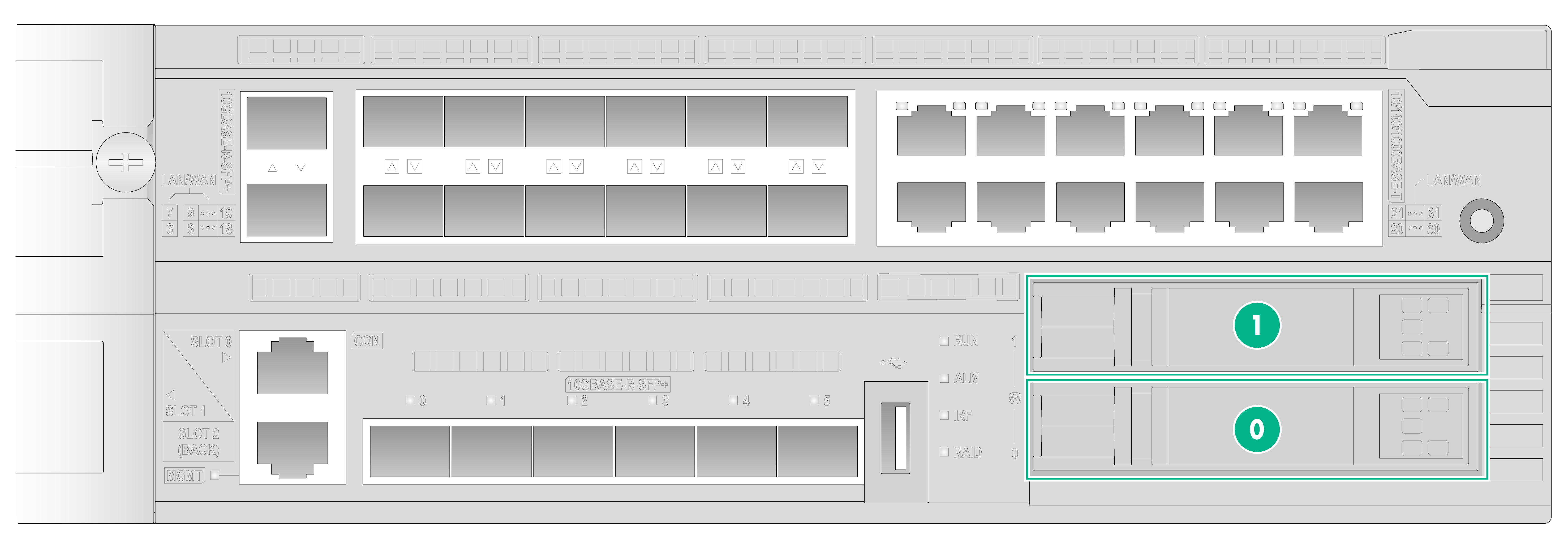
As shown in Figure12-3, the device has two SATA drive slots. You can install H3C SATA drives in the slots and configure RAID.
Before configuring RAID, make sure the device has been installed with a riser card and a storage controller.
Figure12-3 Front panel of the device
|
(0) SATA drive slot 0 (the drive in the slot is named hda) |
|
(1) SATA drive slot 1 (the drive in the slot is named hdb ) |
Creating a RAID array
Before a RAID array is created, the member drives are independent of each other and you can only read from and write to the drives separately.
After a RAID array is created, all member drives will be used as a whole. Reading and writing data to one of the member drives is equivalent to reading and writing data to all member drives. After the RAID array is created, the original data on the member drives will be erased.
Installing hardware
A RAID array setup requires a riser card, storage controller, and SATA drives. The device does not come with these hardware options. Prepare and install these hardware options.
For information about installing riser cards, storage controllers, and SATA drives, see "Installing a storage controller" and "Installing SATA drives."
Configuring drives
Restrictions and guidelines
Make sure the member drives for creating the RAID array each have only one partition with the EXT4 file system format. To view detailed information about a drive, partition a drive, and format a drive, execute the dir, fdisk, and format commands, respectively. For more information about the dir, fdisk, and format commands, see the file system management commands in H3C SR6602-I[IE] AI-Powered ICT Converged Gateways Fundamentals Command Reference.
Procedure
1. Execute the fdisk command in user view to divide each SATA drive into one partition.
<Sysname> fdisk hda: 1
<Sysname> fdisk hdb: 1
By default, each SATA drive has one partition.
2. Execute the dir command in user view to view the file system format of the partition on each drive.
<Sysname> dir hda0:/
Directory of hda0: (EXT4)
0 drw- - Dec 10 2020 17:04:03 VmImages
1 drw- - Sep 04 2020 11:03:21 etc
2 drw- - Sep 04 2020 10:53:15 lost+found
<Sysname> dir hdb0:/
Directory of hdb0: (EXT4)
...
Directory of xxx: (EXT4) indicates that the file system format is EXT4.
3. If the file system format of a partition is not EXT4, execute the format command in user view to format the file system to EXT4.
<Sysname> format hda0: ext4
<Sysname> format hdb0: ext4
4. Reboot the device.
# Execute the reboot command in user view to reboot the device.
<Sysname> reboot
Creating a RAID array
The device allows you to create a RAID array by using a storage controller during the system startup process, and it supports RAID levels 0 and 1.
To create a RAID array:
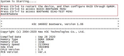
1. Start up the device. When the device enters the BootWare screen, press Ctrl+E as prompted in time to access the BIOS screen.
If you fail to press Ctrl+E in time, the device will start up and enter the CLI.
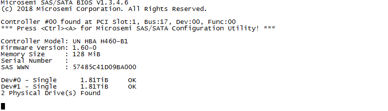
2. From the BIOS screen, press Ctrl+A in time as promoted.
The storage controller information is displayed, as shown in Figure12-5.
If you fail to press Ctrl+A in time, the system returns to the BootWare screen, starts up, and enters the CLI.
Figure12-5 BIOS screen

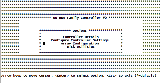
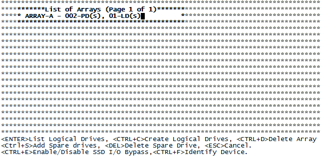
3. On the storage controller configuration screen as shown inFigure12-6, select Array Configuration and press Enter.
Figure12-6 Storage controller configuration screen

Table12-2 Option description
|
Option |
Description |
|
Controller Details |
Allows you to view storage controller configuration information. |
|
Configure Controller Settings |
Allows you to configure settings and restore the default settings for the storage controller. |
|
Array Configuration |
Allows you to create and manage RAID arrays. |
|
Disk Utilities |
Allows you to view physical drive information, locate drives, and format drives. |
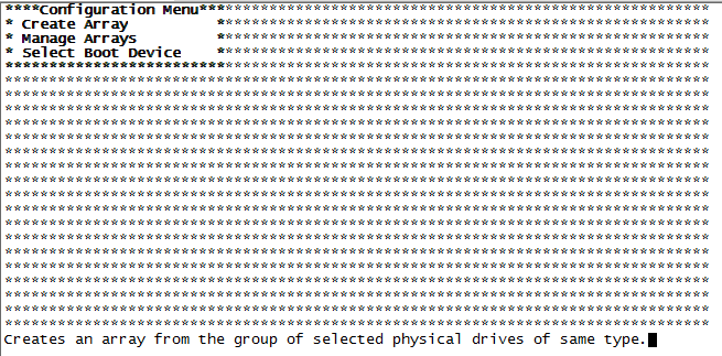
4. On the storage controller configuration screen as shown in Figure12-7, select Create Array and press a key.
Figure12-7 RAID array configuration screen
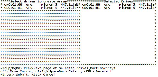
5. Use the spacebar to select drives and then press Enter.
Figure12-8 Selecting drives
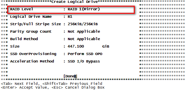
6. Select RAID 0 or RAID 1 as required and then press Enter.
Figure12-9 RAID level configuration
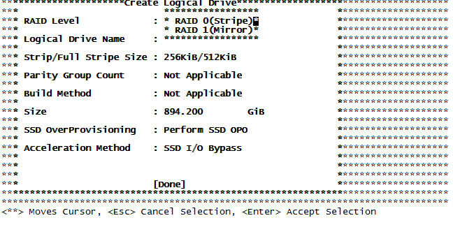
The RAID array information is displayed. In this example, a RAID 1 array is created.
Figure12-10 RAID array information
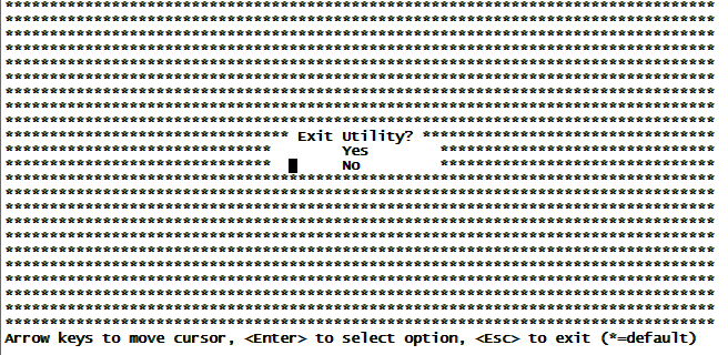
7. Press Esc to exit the RAID configuration screen. Then select Yes and press Enter to exit the RAID configuration and BIOS screen and enter the BootWare screen.
Figure12-11 Exiting the RAID configuration screen
Deleting a RAID array
To remove a member drive from a RAID array and use it as an independent drive, you must delete the RAID array on the device.
To delete a RAID array:
1. Start up the device. When the device enters the BootWare screen, press Ctrl+E as prompted in time to access the BIOS screen.
If you fail to press Ctrl+E in time, the device will start up and enter the CLI.
Figure12-12 BootWare screen

2. From the BIOS screen, press Ctrl+A as promoted in time.
The storage controller information is displayed, as shown in Figure12-13.
If you fail to press Ctrl+A in time, the system returns to the Bootware screen, starts up, and enters the CLI.
Figure12-13 BIOS screen
3. On the storage controller configuration screen as shown in Figure12-14, select Array Configuration and press Enter.
Figure12-14 Storage controller configuration screen
4. Select Manage Arrays and press a key.
Figure12-15 RAID array configuration menu

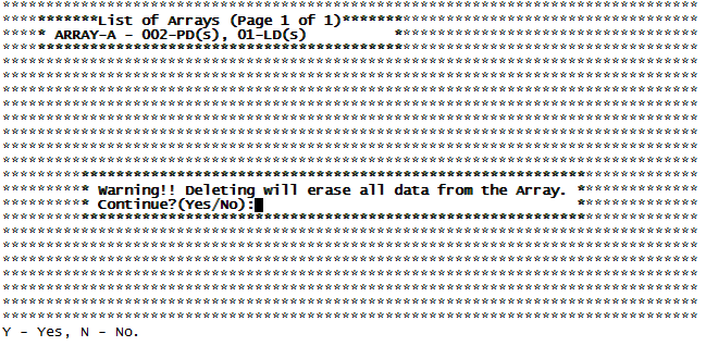
5. Press Ctrl+D to delete the built RAID arrays.
Figure12-16 Deleting the RAID array
6. Enter Yes to confirm the deletion.
Figure12-17 Confirming the deletion
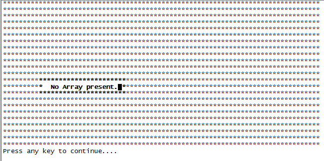
7. Press Esc to exit the storage controller configuration and BIOS screen and enter the BootWare screen.
Figure12-18 Deletion completed
Rebuilding a RAID array
To avoid more data loss, replace a member drive in a RAID array in time when the drive is damaged.
After replacing a member drive, identify whether the drive status is OK from the BIOS screen. You can rebuild the RAID array only when the drive status is correct.
Identifying the drive status
1. Start up the device. When the device enters the BootWare screen, press Ctrl+E as prompted in time to access the BIOS screen.
If you fail to press Ctrl+E in time, the device will start up and enter the CLI.
Figure12-19 BootWare screen

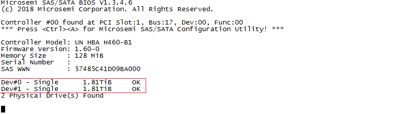
2. From the BIOS screen, press Ctrl+A as promoted in time.
The storage controller information is displayed, as shown in Figure12-20.
Figure12-20 BIOS screen
Rebuilding the RAID array
· A RAID 0 array cannot be rebuilt. When a member drive of a RAID 0 array is damaged, the RAID group is also damaged, and the data in the RAID group is damaged and cannot be recovered. To continue to use a RAID 0 array, you must delete the damaged RAID 0 array first, and then create a new RAID 0 array. For the method of deleting and creating a RAID 0 array, see "Creating a RAID array" and "Deleting a RAID array," respectively.
· A RAID 1 array can be rebuilt automatically. After you replace a damaged member drive, the RAID 1 array will automatically recognize the new drive and add it to the RAID group to replace the damaged member drive in the RAID group. After the RAID is rebuilt, the original data in the newly added member drive will be erased.
13 Troubleshooting
Startup failure of the device
Symptom
The device fails to start up, and the RUN LED on the device is off.
Solution
To resolve the issue:
1. Troubleshoot the power supplies if all LEDs of the device are off. For the power supply troubleshooting method, see "Power supply failure."
2. Make sure the DIMMs are installed correctly and securely. As a best practice, remove and reinstall the DIMMs to ensure that they are installed correctly and securely.
3. Install the DIMMs in idle slots and power on the device again.
4. If the issue persists, contact H3C Support.
Power supply failure
Symptom
The device fails to be powered on, and the status LED on the power supply is off.
Solution
To resolve the issue:
1. Verify that the power cord is connected correctly and reliably.
2. Verify that the power source is as required by the power supply.
3. Verify that the device operates at acceptable temperature ranges and the power supply has good ventilation.
4. If the issue persists, contact H3C Support.
To replace a power supply, see "Replacing a power supply."
Fan tray failure
Symptom
The system reports a fan tray failure:
%May 22 10:13:17:666 2020 H3C DEV/2/FAN_FAILED: Fan 2 failed.
The status LED on the fan tray is steady yellow.
Solution
To resolve the issue:
1. Verify that the air inlet and outlet vents of the chassis are not blocked. Clear the obstructions if any.
2. Replace the fan tray.
3. If the issue persists, contact H3C Support.
Configuration terminal display issue
No display
Symptom
The configuration terminal does not have display when the device is powered on.
Solution
To resolve the issue:
1. Verify that the power system is operating correctly.
2. Verify that the console cable is correctly connected.
3. Verify that the console cable does not have any issues and the terminal settings are correct.
4. If the issue persists, contact H3C Support.
Garbled display
Symptom
The display on the configuration terminal is garbled.
Solution
To resolve the issue:
1. Verify that the terminal parameters are configured as follows:
¡ Baud rate—9,600.
¡ Data bits—8.
¡ Stop bits—1.
¡ Parity—None.
¡ Flow control—None.
2. If the issue persists, contact H3C Support.