- Table of Contents
- Related Documents
-
| Title | Size | Download |
|---|---|---|
| 02-Appendix | 2.44 MB |
Contents
Appendix A Server specifications
Server models and chassis view
Appendix B Component specifications
DIMM rank classification label
Drive configurations and numbering
Riser cards for riser connector 1 or 2
Riser cards for riser connector 3
550 W Platinum power supply (PSR550-12A, PSR550-12A-1, and PSR550-12A-2)
550 W Platinum power supply (PS-2551-9L3)
550 W Platinum power supply (GW-CRPS550N)
550 W high-efficiency Platinum power supply
800 W Platinum power supply (PSR800-12A)
800 W Platinum power supply (PS-2801-9L3)
800 W Platinum power supply (GW-CRPS800B)
800 W 336 V high-voltage DC power supply
850 W high-efficiency Platinum power supply
Diagnostic panel specifications
Appendix C Managed hot removal of NVMe drives
Performing a managed hot removal in Windows
Performing a managed hot removal in Linux
Performing a managed hot removal from the CLI
Performing a managed hot removal from the Intel® ASM Web interface
Appendix D Environment requirements
About environment requirements
General environment requirements
Operating temperature requirements
8SFF server with an 8SFF drive configuration
8SFF server with a 16SFF/24SFF drive configuration
25SFF server with any drive configuration
8LFF server with any drive configuration
12LFF server with any drive configuration
Appendix A Server specifications
The information in this document might differ from your product if it contains custom configuration options or features.
Server models and chassis view
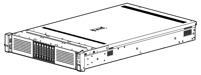
H3C UniServer R4900 G3 servers are 2U rack servers with two Intel Purley or Jintide-C series processors. They are suitable for cloud computing, IDC, and enterprise networks built based on new generation infrastructure.
Figure 1 Chassis view
The servers come in the models listed in Table 1. These models support different drive configurations. For more information about drive configuration and compatible storage controller configuration, see "Drive configurations and numbering."
Table 1 R4900 G3 server models
|
Model |
Maximum drive configuration |
|
8SFF |
24 SFF drives at the front. |
|
8LFF |
8 LFF drives at the front. |
|
12LFF |
12 LFF drives at the front + 4 LFF and 4SFF drives at the rear. |
|
25SFF |
25 SFF drives at the front + 2 LFF drives and 4 SFF drives at the rear. |
Technical specifications
|
Item |
8SFF |
8LFF |
12LFF |
25SFF |
|
Dimensions (H × W × D) |
· Without a security bezel: 87.5 × 445.4 × 748 mm (3.44 × 17.54 × 29.45 in) · With a security bezel: 87.5 × 445.4 × 771 mm (3.44 × 17.54 × 30.35 in) |
|||
|
Max. weight |
32.75 kg (72.20 lb) |
27.33 kg (60.25 lb) |
32.75 kg (72.20 lb) |
|
|
Processors |
2 × Intel Purley or Jintide-C series processors (Up to 3.6 GHz base frequency, maximum 205 W power consumption, and 38.5 MB cache per processor) |
|||
|
Memory |
24 × DIMMs |
|||
|
Chipset |
Intel C622 Lewisburg chipset |
|||
|
Network connection |
· 1 × onboard 1 Gbps HDM dedicated network port · 1 × mLOM network adapter connector (NCSI-capable) |
|||
|
· 6 × USB connectors: ¡ 5 × USB 3.0 connectors (one at the server front, two at the server rear, and two on the system board) ¡ 1 × USB 2.0 connector (provided by the left chassis ear with a USB 2.0 connector) ¡ 1 × onboard mini-SAS connector (×8 SATA connectors) ¡ 1 × onboard ×1 SATA connector · 1 × RJ-45 HDM dedicated port at the server rear · 2 × VGA connectors (one at the server rear and one at the server front) · 1 × BIOS serial port at the server rear |
||||
|
Expansion slots |
10 × PCIe 3.0 modules (eight standard PCIe modules, one Mezzanine storage controller, and one network adapter) |
|||
|
· External USB optical drives · Internal SATA optical drive The internal SATA optical drive is available only when the optical drive enablement option is installed. |
External USB optical drives |
External USB optical drives |
External USB optical drives |
|
|
Power supplies |
2 × hot-swappable power supplies in redundancy For more information, see "Power supplies." |
|||
|
Standards |
CCC SEPA |
|||
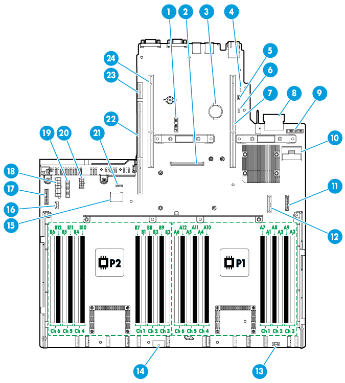
Components
Figure 2 R4900 G3 server components
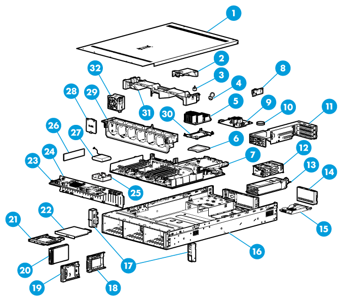
Table 2 R4900 G3 server components
|
Description |
|
|
(1) Access panel |
N/A |
|
(2) Power supply air baffle |
Provides ventilation aisles for power supplies. |
|
(3) Chassis-open alarm module |
Generates a chassis open alarm every time the access panel is removed. The alarms can be displayed from the HDM Web interface. |
|
(4) NVMe VROC module |
Works with VMD to provide RAID capability for the server to virtualize storage resources of NVMe drives. |
|
(5) Processor heatsink |
Cools the processor. |
|
(6) Processor |
Integrates a memory processing unit and a PCIe controller to provide data processing capabilities for the server. |
|
(7) System board |
One of the most important parts of a server, on which multiple components are installed, such as processor, memory, and fan. It is integrated with basic server components, including the BIOS chip, HDM chip, and PCIe connectors. |
|
(8) Dual SD card extended module |
Provides SD card slots. |
|
(9) Storage controller |
Provides RAID capability for the server to virtualize storage resources of SAS/SATA drives. It supports RAID configuration, RAID capability expansion, online upgrade, and remote configuration. |
|
(10) System battery |
Supplies power to the system clock. |
|
(11) Riser card |
Installed in the server to provide additional slots for PCIe modules. |
|
(12) Drive cage |
Encloses drives. |
|
(13) Power supply |
Supplies power to the server. It supports hot swapping and 1+1 redundancy. |
|
(14) Riser card blank |
Installed on an empty riser card connector to ensure good ventilation. |
|
(15) mLOM network adapter |
Installed on the mLOM network adapter connector of the system board for network expansion. |
|
(16) Chassis |
N/A |
|
(17) Chassis ears |
Attach the server to the rack. The right ear is integrated with the front I/O component. The left ear is available in two types: one with VGA and USB 2.0 connectors and one without connectors. |
|
(18) Serial label pull tab module |
Provides the device serial number, HDM default login settings, and document QR code. The module is available only for SFF server models. |
|
(19) Diagnostic panel |
Displays information about faulty components for quick diagnosis. The LFF diagnostic panel is integrated with a serial label pull tab that provides the HDM default login settings and document QR code. |
|
(20) Drive |
Drive for data storage, which is hot swappable. |
|
(21) M.2 expander module |
Expands the server with a maximum of two SATA M.2 SSDs. |
|
(22) Optical drive |
Used for operating system installation and data backup. |
|
(23) Drive expander module |
Provides connection between drives and a storage controller to expand the number of drives controlled by the storage controller. If no drive expander module is installed, a storage controller can manage a maximum of eight drives. |
|
(24) Drive backplane |
Provides power and data channels for drives. |
|
(25) Supercapacitor holder |
Secures a supercapacitor in the chassis. |
|
(26) Memory |
Stores computing data and data exchanged with external storage. |
|
(27) Supercapacitor |
Supplies power to the flash card of the power fail safeguard module, which enables the storage controller to back up data to the flash card for protection when power outage occurs. |
|
(28) Fan blank |
Installed in an empty fan bay to ensure good ventilation. |
|
(29) Fan cage |
Used for holding fans. |
|
(30) Processor retaining bracket |
Attaches a processor to the heatsink. |
|
(31) Chassis air baffle |
Provides ventilation aisles for airflows in the chassis. |
|
(32) Fan |
Supports hot swapping and N+1 redundancy. |
Front panel
Front panel view
Figure 3, Figure 4, Figure 5, and Figure 6 show the front panel views of 8SFF, 25SFF, 8LFF, and 12LFF servers, respectively.
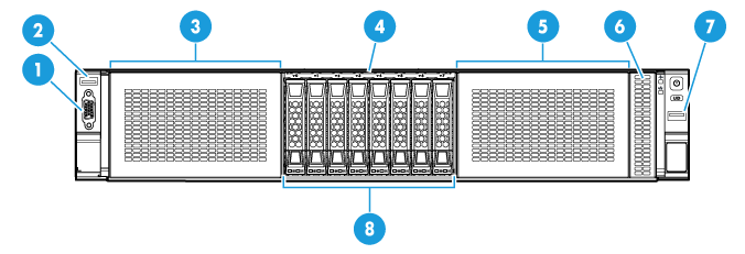
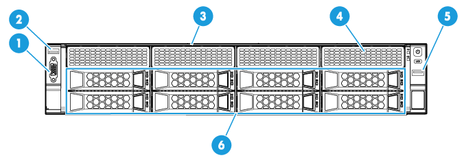
Figure 3 8SFF front panel
|
(1) VGA connector (optional) |
(2) USB 2.0 connector (optional) |
|
(3) Drive cage bay 1 for 8SFF SAS/SATA drives or 8SFF NVMe SSDs (optional) |
|
|
(4) Serial label pull tab |
|
|
(5) Drive cage bay 3 for 8SFF SAS/SATA drives or 8SFF NVMe SSDs (optional) |
|
|
(6) Diagnostic panel or serial label pull tab module (optional) |
(7) USB 3.0 connector |
|
(8) Drive cage bay 2 for 8SFF SAS/SATA drives or 8SFF NVMe SSDs |
|
|
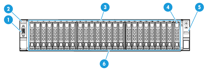
(1) VGA connector (optional) |
(2) USB 2.0 connector (optional) |
|
(3) Serial label pull tab |
(4) Diagnostic panel or serial label pull tab module (optional) |
|
(5) USB 3.0 connector |
(6) 25SFF drives (optional) |
Figure 5 8LFF front panel
|
(1) VGA connector (optional) |
(2) USB 2.0 connector (optional) |
|
(3) Serial label pull tab |
(4) Diagnostic panel (optional) |
|
(5) USB 3.0 connector |
(6) 8LFF SAS/SATA drives |
|
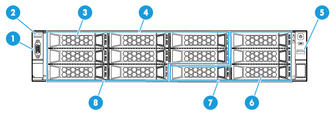
(1) VGA connector (optional) |
(2) USB 2.0 connector (optional) |
|
(3) Diagnostic panel (optional for the 8LFF SAS/SATA+4LFF NVMe drive configuration) |
|
|
(4) Serial label pull tab |
(5) USB 3.0 connector |
|
(6) Diagnostic panel (optional for the 12LFF SAS/SATA drive configuration) |
|
|
(7) SAS/SATA or NVMe drives |
(8) SAS/SATA drives |
LEDs and buttons
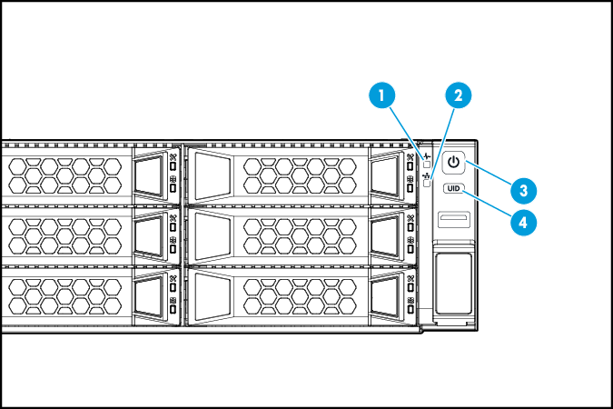
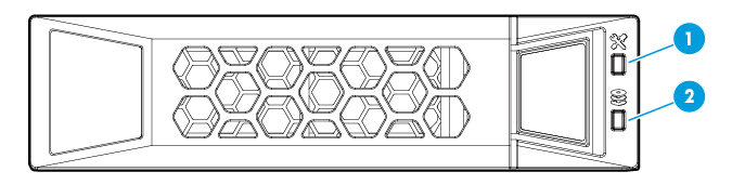
The LED and buttons are the same on all server models. Figure 7 shows the front panel LEDs and buttons. Table 3 describes the status of the front panel LEDs.
Figure 7 Front panel LEDs and buttons
|
(1) Health LED |
(2) mLOM network adapter Ethernet port LED |
|
(3) Power on/standby button and system power LED |
(4) UID button LED |
Table 3 LEDs and buttons on the front panel
|
Button/LED |
Status |
|
Health LED |
· Steady green—The system is operating correctly or a minor alarm has occurred. · Flashing green (4 Hz)—HDM is initializing. · Flashing amber (1 Hz)—A major alarm has occurred. · Flashing red (1 Hz)—A critical alarm has occurred. If a system alarm is present, log in to HDM to obtain more information about the system running status. |
|
mLOM network adapter Ethernet port LED |
· Steady green—A link is present on the port. · Flashing green (1 Hz)—The port is receiving or sending data. · Off—No link is present on the port. |
|
Power on/standby button and system power LED |
· Steady green—The system has started. · Flashing green (1 Hz)—The system is starting. · Steady amber—The system is in Standby state. · Off—No power is present. Possible reasons: ¡ No power source is connected. ¡ No power supplies are present. ¡ The installed power supplies are faulty. ¡ The system power cords are not connected correctly. |
|
UID button LED |
· Steady blue—UID LED is activated. The UID LED can be activated by using the following methods: ¡ Press the UID button LED. ¡ Activate the UID LED from HDM. · Flashing blue: ¡ 1 Hz—The firmware is being upgraded or the system is being managed from HDM. ¡ 4 Hz—HDM is restarting. To restart HDM, press the UID button LED for a minimum of eight seconds. · Off—UID LED is not activated. |
Ports
The server does not provide fixed USB 2.0 or VGA connectors on its front panel. However, you can install a front media module if a USB 2.0 or VGA connection is needed, as shown in Table 4. For detailed port locations, see "Front panel view."
Table 4 Optional ports on the front panel
|
Port |
Type |
Description |
|
USB connector |
USB 3.0/2.0 |
Connects the following devices: · USB flash drive. · USB keyboard or mouse. · USB optical drive for operating system installation. |
|
VGA connector |
DB-15 |
Connects a display terminal, such as a monitor or KVM device. |
Rear panel
Rear panel view
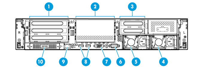
Figure 8 shows the rear panel view.
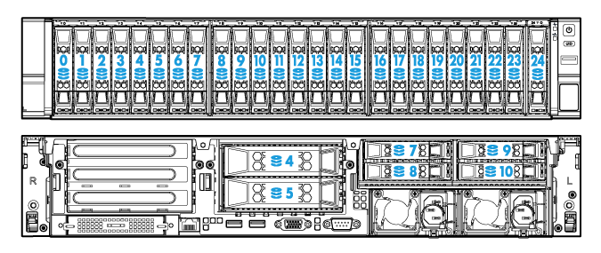
Figure 8 Rear panel components
|
(1) PCIe slots 1 through 3 from the top down (processor 1) |
|
|
(2) PCIe slots 4 through 6 from the top down (processor 2) |
|
|
(3) PCIe slots 7 and 8 from the top down (processor 2) |
(4) Power supply 2 |
|
(5) Power supply 1 |
(6) BIOS serial port |
|
(7) VGA connector |
(8) USB 3.0 connectors |
|
(9) HDM dedicated network port (1 Gbps, RJ-45, default IP address 192.168.1.2/24) |
|
|
(10) mLOM network adapter (slot 9)(optional) |
|
LEDs
Figure 9 shows the rear panel LEDs. Table 5 describes the status of the rear panel LEDs.
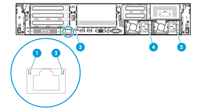
|
(1) Link LED of the Ethernet port |
(2) Activity LED of the Ethernet port |
|
(3) UID LED |
(4) Power supply 1 LED |
|
(5) Power supply 2 LED |
|
Table 5 LEDs on the rear panel
|
LED |
Status |
|
Link LED of the Ethernet port |
· Steady green—A link is present on the port. · Off—No link is present on the port. |
|
Activity LED of the Ethernet port |
· Flashing green (1 Hz)—The port is receiving or sending data. · Off—The port is not receiving or sending data. |
|
UID LED |
· Steady blue—UID LED is activated. The UID LED can be activated by using the following methods: ¡ Press the UID button LED. ¡ Enable UID LED from HDM. · Flashing blue: ¡ 1 Hz—The firmware is being updated or the system is being managed by HDM. ¡ 4 Hz—HDM is restarting. To restart HDM, press the UID button LED for a minimum of eight seconds. · Off—UID LED is not activated. |
|
Power supply LED |
· Steady green—The power supply is operating correctly. · Flashing green (1 Hz)—Power is being input correctly but the system is not powered on. · Flashing green (0.33 Hz)—The power supply is in standby state and does not output power. · Flashing green (2 Hz)—The power supply is updating its firmware. · Steady amber—Either of the following conditions exists: ¡ The power supply is faulty. ¡ The power supply does not have power input, but the other power supply has correct power input. · Flashing amber (1 Hz)—An alarm has occurred on the power supply. · Off—No power supplies have power input, which can be caused by an incorrect power cord connection or power source shutdown. |
Ports
For detailed port locations, see "Rear panel view."
Table 6 Ports on the rear panel
|
Port |
Type |
Description |
|
HDM dedicated network port |
RJ-45 |
Establishes a network connection to manage HDM from its Web interface. |
|
USB connector |
USB 3.0 |
Connects the following devices: · USB flash drive. · USB keyboard or mouse. · USB optical drive for operating system installation. |
|
VGA connector |
DB-15 |
Connects a display terminal, such as a monitor or KVM device. |
|
BIOS serial port |
DB-9 |
The BIOS serial port is used for the following purposes: · Log in to the server when the remote network connection to the server has failed. · Establish a GSM modem or encryption lock connection. |
|
Power receptacle |
Standard single-phase |
Connects the power supply to the power source. |
System board
System board components
Figure 10 System board components
|
(1) TPM/TCM connector |
(2) Mezzanine storage controller connector (slot 10) |
|
(3) System battery |
(4) System maintenance switch 1 |
|
(5) System maintenance switch 2 |
(6) System maintenance switch 3 |
|
(7) PCIe riser connector 1 (processor 1) |
(8) mLOM network adapter connector (slot 9) |
|
(10) Mini-SAS port (×8 SATA ports) |
|
|
(11) Front I/O connector |
(12) Optical/SATA port |
|
(13) Diagnostic panel connector |
|
|
(15) Dual internal USB 3.0 connector |
(16) Front drive backplane AUX connector 2 or rear drive backplane AUX connector |
|
(17) Chassis-open alarm module, front VGA, and USB 2.0 connector |
(18) Front drive backplane power connector 2 and SATA M.2 SSD power connector |
|
(19) Front drive backplane AUX connector 1 |
(20) Rear drive backplane power connector |
|
(21) NVMe VROC module connector |
(22) PCIe riser connector 3 (processor 2) |
|
(23) Dual SD card extended module connector |
(24) PCIe riser connector 2 (processor 2) |
System maintenance switches
Use the system maintenance switches if you forget HDM username, HDM password, or BIOS password, or need to restore default BIOS settings, as described in Table 7. To identify the location of the switches on the system board, see Figure 10.
Table 7 System maintenance switches
|
Item |
Description |
Remarks |
|
System maintenance switch 1 |
· Pins 1-2 jumped (default)—HDM login requires the username and password of a valid HDM user account. · Pins 2-3 jumped—HDM login requires the default username and password. |
For security purposes, jump pins 1 and 2 after you complete tasks with the default username and password as a best practice. |
|
System maintenance switch 2 |
· Pins 1-2 jumped (default)—Normal server startup. · Pins 2-3 jumped—Clears all passwords from the BIOS at server startup. |
To clear all passwords from the BIOS, jump pins 2 and 3 and then start the server. All the passwords will be cleared from the BIOS. Before the next server startup, jump pins 1 and 2 to perform a normal server startup. |
|
System maintenance switch 3 |
· Pins 1-2 jumped (default)—Normal server startup. · Pins 2-3 jumped—Restores the default BIOS settings. |
To restore the default BIOS settings, jump pins 2 and 3 for over 30 seconds and then jump pins 1 and 2 for normal server startup. |
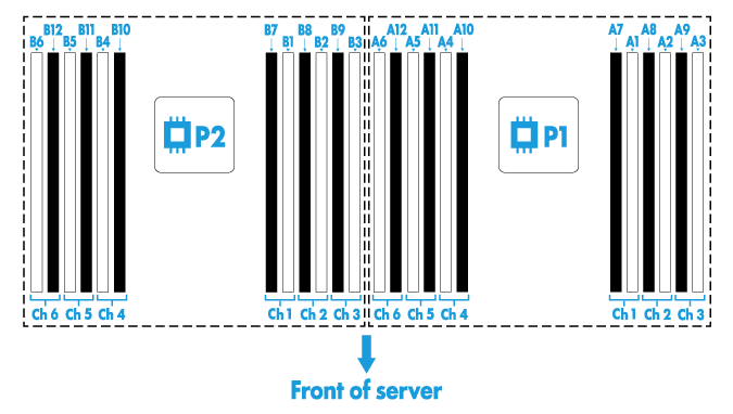
DIMM slots
The server provides 6 DIMM channels per processor, 12 channels in total. Each channel contains one white-coded slot and one black-coded slot, as shown in Table 8.
Table 8 DIMM slot numbering and color-coding scheme
|
Processor |
DlMM slots |
|
Processor 1 |
A1 through A6 (white coded) A7 through A12 (black coded) |
|
Processor 2 |
B1 through B6 (white coded) B7 through B12 (black coded) |
Figure 11 shows the physical layout of the DIMM slots on the system board. For more information about the DIMM slot population rules, see the guidelines in "Installing DIMMs."
Figure 11 DIMM physical layout
Appendix B Component specifications
For components compatible with the server and detailed component information, visit the query tool at http://www.h3c.com/cn/Service/Document_Software/Document_Center/Server/.
About component model names
The model name of a hardware option in this document might differ slightly from its model name label.
A model name label might add a prefix or suffix to the hardware-coded model name for purposes such as identifying the matching server brand or applicable region. For example, the DDR4-2666-8G-1Rx8-R memory model represents memory module labels including DDR4-2666-8G-1Rx8-R, DDR4-2666-8G-1Rx8-R-F, and DDR4-2666-8G-1Rx8-R-S, which have different suffixes.
DIMMs
The server provides 6 DIMM channels per processor, 12 channels in total. Each DIMM channel has two DIMM slots and supports a maximum of eight ranks. For the physical layout of DIMM slots, see "DIMM slots."
DIMM rank classification label
A DIMM rank is a set of memory chips that the system accesses while writing or reading from the memory. On a multi-rank DIMM, only one rank is accessible at a time.
To determine the rank classification of a DIMM, use the label attached to the DIMM, as shown in Figure 12.
Figure 12 DIMM rank classification label
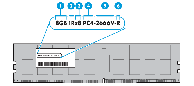
Table 9 DIMM rank classification label description
|
Callout |
Description |
Remarks |
|
1 |
Capacity |
N/A |
|
2 |
Number of ranks |
N/A |
|
3 |
Data width |
· ×4—4 bits. · ×8—8 bits. |
|
4 |
DIMM generation |
Only DDR4 is supported. |
|
5 |
Data rate |
· 2133P—2133 MHz. · 2400T—2400 MHz. · 2666V—2666 MHz. · 2933Y—2933 MHz. |
|
6 |
DIMM type |
· L—LRDIMM. · R—RDIMM. |
HDDs and SSDs
Drive LEDs
The server supports SAS, SATA, and NVMe drives, of which SAS and SATA drives support hot swapping and NVMe drives support hot insertion and managed hot removal. You can use the LEDs on a drive to identify its status after it is connected to a storage controller.
Figure 13 shows the location of the LEDs on a drive.
|
(1) Fault/UID LED |
(2) Present/Active LED |
To identify the status of a SAS or SATA drive, use Table 3. To identify the status of an NVMe drive, use Table 4.
Table 10 SAS/SATA drive LED description
|
Fault/UID LED status |
Present/Active LED status |
Description |
|
Flashing amber (0.5 Hz) |
Steady green/Flashing green (4.0 Hz) |
A drive failure is predicted. As a best practice, replace the drive before it fails. |
|
Steady amber |
Steady green/Flashing green (4.0 Hz) |
The drive is faulty. Replace the drive immediately. |
|
Steady blue |
Steady green/Flashing green (4.0 Hz) |
The drive is operating correctly and is selected by the RAID controller. |
|
Off |
Flashing green (4.0 Hz) |
The drive is performing a RAID migration or rebuilding, or the system is reading or writing data to the drive. |
|
Off |
Steady green |
The drive is present but no data is being read or written to the drive. |
|
Off |
Off |
The drive is not securely installed. |
Table 11 NVMe drive LED description
|
Fault/UID LED status |
Present/Active LED status |
Description |
|
Flashing amber (0.5 Hz) |
Off |
The managed hot removal process is completed. You can remove the drive safely. |
|
Flashing amber (4.0 Hz) |
Off |
The drive is in hot insertion process. |
|
Steady amber |
Steady green/Flashing green (4.0 Hz) |
The drive is faulty. Replace the drive immediately. |
|
Steady blue |
Steady green/Flashing green (4.0 Hz) |
The drive is operating correctly and selected by the RAID controller. |
|
Off |
Flashing green (4.0 Hz) |
The drive is performing a RAID migration or rebuilding, or the system is reading or writing data to the drive. |
|
Off |
Steady green |
The drive is present but no data is being read or written to the drive. |
|
Off |
Off |
The drive is not securely installed. |
Drive configurations and numbering
Unless otherwise specified, the term "standard" in tables Table 5, Table 7, Table 9, and Table 10 refers to a standard storage controller with 8 internal SAS ports, the RAID-LSI-9361-8i(1G)-A1-X for example.
8SFF server
Table 5 presents the drive configurations available for the 8SFF server and their compatible types of storage controllers and NVMe SSD expander modules.
These drive configurations use different drive cage bays and drive numbering schemes, as shown in Table 6.
Table 12 Drive, storage controller, and NVMe SSD expander module configurations (8SFF server)
|
Drive backplane and drive expander module |
Drive configuration |
Storage controller |
NVMe SSD expander module or riser card |
|
Front 8SFF drive cage module |
8SFF (8 front SFF SAS/SATA drives in drive cage bay 2) |
· Embedded RSTe · Mezzanine · Standard in PCIe slot 2 or 6 |
N/A |
|
16SFF (16 front SFF SAS/SATA drives in drive cage bays 2 and 3) |
· Mezzanine + standard in PCIe slot 6 · Standard controller RAID-LSI-9460-16i(4G) or RAID-LSI-9560-LP-16i-8GB in PCIe slot 6 · 2 × standard controllers in PCIe slots 3 and 6 |
N/A |
|
|
16SFF (8 front SFF SAS/SATA drives in drive cage bay 2 + 8 front SFF NVMe drives in drive cage bay 3) |
Embedded RSTe |
· 1 × 8-port NVMe SSD expander module in PCIe slot 2 · 2 × 4-port NVMe SSD expander modules in PCIe slots 2 and 5 · 2 × RC-FHHL/NVMe-2U-G3-1 riser cards on riser connectors 1 and 2 |
|
|
Mezzanine |
· 1 × 8-port NVMe SSD expander module in PCIe slot 2 · 2 × 4-port NVMe SSD expander modules in PCIe slots 2 and 5 · 2 × RC-FHHL/NVMe-2U-G3-1 riser cards on riser connectors 1 and 2 |
||
|
Standard in PCIe slot 6 |
· 1 × 8-port NVMe SSD expander module in PCIe slot 2 · 2 × 4-port NVMe SSD expander modules in PCIe slots 2 and 5 |
||
|
Standard in PCIe slot 4 |
2 × RC-FHHL/NVMe-2U-G3-1 riser cards on riser connectors 1 and 2 |
||
|
24SFF (16 front SFF SAS/SATA drives in drive cage bays 1 and 2 + 8 front SFF NVMe drives in drive cage bay 3) |
· Standard controller RAID-LSI-9460-16i(4G) in PCIe slot 6 · Mezzanine + standard in PCIe slot 6 |
1 × 8-port NVMe SSD expander module in PCIe slot 2 |
|
|
2 × standard controllers in PCIe slots 6 and 8 |
2 × 4-port NVMe SSD expander modules in PCIe slots 2 and 5 |
||
|
2 × standard in PCIe slots 4 and 8 |
2 × RC-FHHL/NVMe-2U-G3-1 riser cards on riser connectors 1 and 2 |
||
|
24SFF (24 front SFF SAS/SATA drives in drive cage bays 1, 2, and 3) |
Standard in PCIe slot 5 + standard controller RAID-LSI-9460-16i(4G) in PCIe slot 6 |
N/A |
|
|
8SFF (8 front SFF NVMe drives in drive cage bay 2) |
N/A |
· 1 × 8-port NVMe SSD expander module in PCIe slot 2 · 2 × 4-port NVMe SSD expander modules in PCIe slots 2 and 5 · 2 × RC-FHHL/NVMe-2U-G3-1 riser cards on riser connectors 1 and 2 |
|
|
12SFF (8 front SFF NVMe drives in drive cage bay 2 + 4 front SFF NVMe drives in the first four slots of drive cage bay 3) |
N/A |
RC-HHHL/NVMe-2U-G3-2 riser card on riser connector 3 + 2 × RC-FHHL/NVMe-2U-G3-1 riser cards on riser connectors 1 and 2 |
|
|
16SFF (16 front SFF NVMe drives in drive cage bays 2 and 3) |
N/A |
· 2 × 8-port NVMe SSD expander modules in PCIe slots 2 and 5 · 4 × 4-port NVMe SSD expander modules in PCIe slots 1, 2, 5, and 7 |
|
|
20SFF (8 front SFF SAS/SATA drives in drive cage 1 + 8 front SFF NVMe drives in drive cage bay 2 + 4 front SFF NVMe drives in the first four slots of drive cage bay 3) |
· Embedded RSTe · Mezzanine · Standard in PCIe slot 4 |
RC-HHHL/NVMe-2U-G3-2 riser card on riser connector 3 + 2 × RC-FHHL/NVMe-2U-G3-1 riser cards on riser connectors 1 and 2 |
|
|
24SFF (8 front SFF SAS/SATA drives in drive cage bay 1 + 16 front SFF NVMe drives in drive cage bays 2 and 3) |
Embedded RSTe |
· 2 × 8-port NVMe SSD expander modules in PCIe slots 2 and 5 · 4 × 4-port NVMe SSD expander modules in PCIe slots1, 2, 5, and 7 |
|
|
Mezzanine |
· 2 × 8-port NVMe SSD expander modules in PCIe slots 2 and 5 · 4 × 4-port NVMe SSD expander modules in PCIe slots1, 2, 5, and 7 |
||
|
Standard in PCIe slot 6 |
· 2 × 8-port NVMe SSD expander modules in PCIe slots 2 and 5 · 4 × 4-port NVMe SSD expander modules in PCIe slots1, 2, 5, and 7 |
||
|
24SFF (24 front SFF NVMe drives) |
N/A |
3 × 8-port NVMe SSD expander modules in PCIe slots 2, 5, and 7 |
|
|
BP-24SFF-NVMe-R4900-G3 drive backplane |
24SFF (24 front SFF NVMe drives) |
N/A |
3 × 8-port NVMe SSD expander modules in PCIe slots 1, 2, and 5 |
|
|
NOTE: Front 8SFF drive cage modules include front 8SFF NVMe drive cage modules and front 8SFF NVMe drive cage modules. For more information about SAS/SATA and NVMe drive cage modules, see "_Ref6494403." |
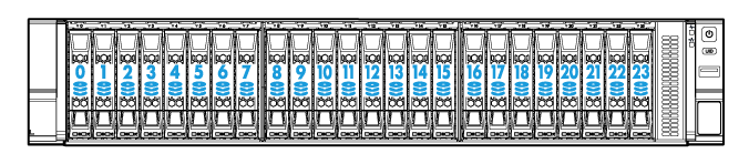
Table 13 Drive population and drive numbering schemes (8SFF server)
|
Drive configuration |
Drive cage bay 1 |
Drive cage bay 2 |
Drive cage bay 3 |
Drive numbering |
|
8SFF |
Unused |
Used |
Unused |
See Figure 14. |
|
16SFF |
Unused |
Used |
Used |
See Figure 15. |
|
24SFF |
Used |
Used |
Used |
|
|
NOTE: For the location of the drive cage bays on the front panel of the server, see "Front panel view." |
Figure 14 Drive numbering for 8SFF drive configurations (8SFF server)
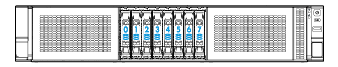
Figure 15 Drive numbering for 16SFF drive configurations (8SFF server)
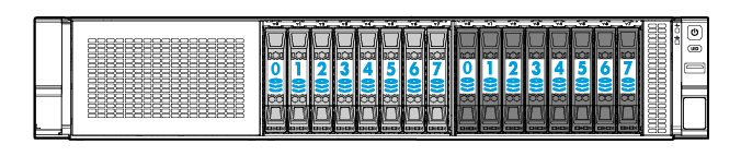
Figure 16 Drive numbering for the 24SFF drive configuration (8SFF server)
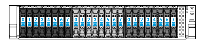
Figure 17 Drive numbering for the 24SFF NVMe drive configuration (8SFF server)
25SFF server
Table 7 presents the drive configurations available for the 25SFF server and their compatible types of storage controllers and NVMe SSD expander modules.
Table 14 Drive, storage controller, and NVMe SSD expander module configurations (25SFF server)
|
Drive backplane and drive expander module |
Drive configuration |
Storage controller |
NVMe SSD expander module or riser card |
|
BP-25SFF-R4900 25SFF drive backplane + drive expander module |
25SFF (25 front SFF SAS/SATA drives) |
· Mezzanine · Standard in PCIe slot 2 |
N/A |
|
27SFF (25 front SFF and 2 rear SFF SAS/SATA drives) |
· Mezzanine · Standard in PCIe slot 2 The rear drives must be connected to the drive expander module. |
N/A |
|
|
27SFF (25 front SFF SAS/SATA drives + 2 rear SFF SAS/SATA drives in a 2SFF UniBay drive cage) |
Standard LSI controller in PCIe slot 1 for the rear drives + standard LSI controller in PCIe slot 2 for the front drives |
N/A |
|
|
29SFF (25 front SFF and 4 rear SFF SAS/SATA drives) |
· Mezzanine · Standard in PCIe slot 2 The rear drives must be connected to the drive expander module. |
N/A |
|
|
29SFF+2LFF (25 front and 4 rear SFF SAS/SATA drives + 2 rear LFF SAS/SATA drives) |
· Mezzanine · Standard in PCIe slot 2 The rear drives must be connected to the drive expander module. |
N/A |
|
|
29SFF (25 front SFF SAS/SATA drives + 4 rear SAS/SATA/NVMe drives in the 4SFF UniBay drive cage) |
· Mezzanine · Standard in PCIe slot 2 · 2 × standard controllers in PCIe slots 1 and 2 (with the controller in slot 1 connected to the 4SFF system disks) |
· 1 × 4-port NVMe SSD expander module in PCIe slot 5 · RC-FHHL/NVMe-2U-G3-1 riser card on riser connector 2 |
|
|
BP2-25SFF-2U-G3 25SFF drive backplane |
25SFF (25 front SFF SAS/SATA drives) |
· Mezzanine · Standard in PCIe slot 6 |
N/A |
|
27SFF (25 front SFF SAS/SATA drives + 2 rear SFF SAS/SATA drives) |
· Mezzanine · Standard in PCIe slot 6 The rear drives must be connected to the drive backplane. |
N/A |
|
|
NOTE: The BP2-25SFF-2U-G3 25SFF drive backplane provides the function of a drive expander module and can be used without any drive expander module. |
These drive configurations use different drive numbering schemes, as shown in Table 8.
Table 15 Drive numbering schemes (25SFF server)
|
Drive configuration |
Drive numbering |
|
25SFF (25 SFF front drives) |
See Figure 18. |
|
27SFF (25 SFF front drives and 2 SFF rear drives) |
See Figure 19. |
|
29SFF (25 SFF front drives and 4 SFF rear drives) |
See Figure 20. |
|
29SFF+2LFF (25 SFF front drives, 4 SFF rear drives, and 2 LFF rear drives) |
See Figure 21. |
Figure 18 Drive numbering for the 25SFF configuration (25SFF server)
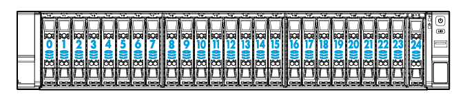
Figure 19 Drive numbering for the 27SFF (25 front+2 rear) drive configuration (25SFF server)
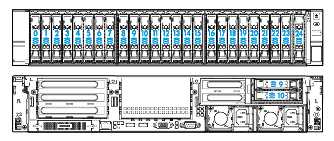
Figure 20 Drive numbering for the 29SFF (25 front+4 rear) drive configuration (25SFF server)
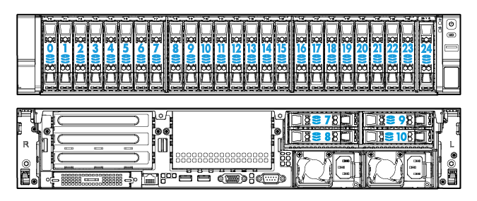
Figure 21 Drive numbering for the 29SFF (25 front+4 rear)+2LFF drive configuration (25SFF server)
8LFF server
The 8LFF server supports only one drive configuration.
Table 9 presents this drive configuration and its compatible types of storage controllers and NVMe SSD expander modules.
Table 16 Drive, storage controller, and NVMe SSD expander module configurations (8LFF server)
|
Drive backplane and drive expander module |
Drive configuration |
Storage controller |
NVMe SSD expander module or riser card |
|
N/A |
8LFF (8 LFF front SAS/SATA drives) |
· Embedded RSTe · Mezzanine · Standard in PCIe slot 2 or 6 |
N/A |
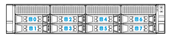
Figure 22 Drive numbering for the 8LFF drive configuration (8LFF server)
12LFF server
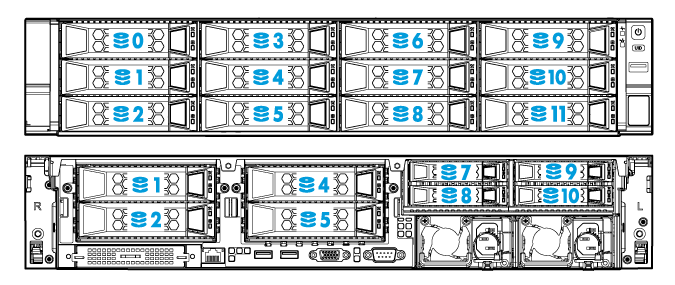
Table 10 presents the drive configurations available for the 12LFF server, their compatible types of storage controllers and NVMe SSD expander modules, and drive numbering schemes.
Table 17 Drive configurations supported by the 12LFF server
|
Drive backplane and drive expander module |
Drive configuration |
Storage controller |
NVMe SSD expander module or riser card |
Drive numbering |
|
BP-12LFF-R4900 drive backplane + drive expander module |
12LFF (12 front LFF SAS/SATA drives) |
· Mezzanine · Standard in PCIe slot 2 |
N/A |
See Figure 23. |
|
12LFF+2SFF (12 front LFF SAS/SATA drives + 2 rear SFF SAS/SATA drives) |
· Mezzanine · Standard in PCIe slot 2 The rear drives must be connected to the drive expander module. |
N/A |
See Figure 24. |
|
|
12LFF+2SFF (12 front LFF SAS/SATA drives + 2 rear SFF SAS/SATA drives in a 2SFF UniBay drive cage) |
Standard LSI controller in PCIe slot 1 for the rear drives + standard LSI controller in PCIe slot 2 for the front drives |
N/A |
See Figure 24. |
|
|
12LFF+4SFF (12 front LFF SAS/SATA drives + 4 rear SFF SAS/SATA or NVMe drives in 4SFF UniBay drive cage) |
· Mezzanine · Standard in PCIe slot 2 |
· 1 × 4-port NVMe SSD expander module in PCIe slot 5 · RC-FHHL/NVMe-2U-G3-1 riser card on riser connector 2 |
See Figure 25. |
|
|
14LFF (12 front and 2 rear LFF SAS/SATA drives) |
· Mezzanine · Standard in PCIe slot 2 |
N/A |
See Figure 26. |
|
|
16LFF (12 front and 4 rear LFF SAS/SATA drives) |
· Mezzanine · Standard in PCIe slot 8 |
N/A |
See Figure 27. |
|
|
14LFF+2SFF (12 front and 2 rear LFF SAS/SATA drives + 2 rear SFF SAS/SATA drives) |
· Mezzanine · Standard in PCIe slot 2 |
N/A |
See Figure 28. |
|
|
14LFF+4SFF (12 front and 2 rear LFF SAS/SATA drives + 4 rear SFF SAS/SATA drives) |
· Mezzanine · Standard in PCIe slot 2 |
N/A |
See Figure 29. |
|
|
16LFF+2SFF (12 front and 4 rear LFF SAS/SATA drives + 2 rear SFF SAS/SATA drives) |
· Mezzanine · Standard in PCIe slot 8 |
N/A |
See Figure 30. |
|
|
16LFF+4SFF (12 front and 4 rear LFF SAS/SATA drives + 4 rear SFF SAS/SATA drives) |
Mezzanine |
N/A |
See Figure 31. |
|
|
BP-12LFF-NVMe-2U-G3 or BP-12LFF-4UniBay-2U drive backplane |
(8 front LFF SAS/SATA drives + 4 front LFF NVMe drives) |
Embedded RSTe |
· 1 × 4-port NVMe SSD expander module in PCIe slot 2 · RC-FHHL/NVMe-2U-G3-1 riser card on riser connector 1 |
See Figure 23. |
|
Mezzanine |
· 1 × 4-port NVMe SSD expander module in PCIe slot 2 · RC-FHHL/NVMe-2U-G3-1 riser card on riser connector 1 |
|||
|
Standard in PCIe slot 6 |
1 × 4-port NVMe SSD expander module in PCIe slot 5 |
|||
|
Standard in PCIe slot 4 |
RC-FHHL/NVMe-2U-G3-1 riser card on riser connector 2 |
|||
|
12LFF + 2SFF (8 front LFF SAS/SATA drives + 4 front LFF NVMe drives + 2 rear SFF SAS/SATA drives) |
2 × standard controllers in PCIe slots 1 and 2 |
· 1 × 4-port NVMe SSD expander module in PCIe slot 5 · RC-FHHL/NVMe-2U-G3-1 riser card on riser connector 2 |
See Figure 24. |
|
|
12LFF + 2SFF (8 front LFF SAS/SATA drives + 4 front LFF NVMe drives + 2 rear SFF NVMe drives) |
Standard in PCIe slot 1 + standard controller RAID-LSI-9460-8i(2G) or RAID-LSI-9460-8i(4G) in PCIe slot 2 |
· 1 × 4-port NVMe SSD expander module in PCIe slot 5 · RC-FHHL/NVMe-2U-G3-1 riser card on riser connector 2 |
See Figure 24. |
|
|
12LFF (8 front LFF SAS/SATA drives + 4 front LFF SAS/SATA or NVMe drives in AnyBay slots 8 to 11) |
Standard controller RAID-LSI-9460-16i(4G) in PCIe slot 6 |
1 × 4-port NVMe SSD expander module in PCIe slot 5 |
See Figure 23. |
|
|
Standard controller RAID-LSI-9460-16i(4G) in PCIe slot 4 |
RC-FHHL/NVMe-2U-G3-1 riser card on riser connector 2 |
|||
|
Standard in PCIe slot 6 + Mezzanine NOTE: The standard controller is for front drives 8 to 11. The Mezzanine controller is for front drives 0 to 7. |
1 × 4-port NVMe SSD expander module in PCIe slot 5 |
|||
|
Standard in PCIe slot 4 + Mezzanine NOTE: The standard controller is for front drives 8 to 11. The Mezzanine controller is for front drives 0 to 7. |
RC-FHHL/NVMe-2U-G3-1 riser card on riser connector 2 |
|||
|
Standard controllers in PCIe slots 1 and 2 |
· 1 × 4-port NVMe SSD expander module in PCIe slot 5 · RC-FHHL/NVMe-2U-G3-1 riser card on riser connector 2 |
|||
|
12LFF+2SFF (8 front LFF SAS/SATA drives + 4 front LFF SAS/SATA or NVMe drives in AnyBay slots 8 to 11 + 2 rear SFF SAS/SATA drives) |
· Standard in PCIe slot 6 (for front drives 8 to 11)+ Mezzanine (for front drives 0 to 7) · Standard in PCIe slot 1 + standard controller RAID-LSI-9460-16i(4G) in PCIe slot 6 |
1 × 4-port NVMe SSD expander module in PCIe slot 5 |
See Figure 24. |
|
|
· Standard in PCIe slot 4 (for front drives 8 to 11)+ Mezzanine (for front drives 0 to 7) · Standard in PCIe slot 1 + standard controller RAID-LSI-9460-16i(4G) in PCIe slot 4 |
RC-FHHL/NVMe-2U-G3-1 riser card on riser connector 2 |
|||
|
12LFF + 2SFF (8 front LFF SAS/SATA drives + 4 front LFF SAS/SATA drives + 2 rear SFF SAS/SATA drives) |
· Standard in PCIe slot 6 (for front drives 8 to 11 and rear drives)+ Mezzanine (for front drives 0 to 7) · Standard in PCIe slot 1 + standard controller RAID-LSI-9460-16i(4G) in PCIe slot 6 |
N/A |
See Figure 24. |
|
|
BP2-12LFF-2U-G3 12LFF drive backplane |
12LFF (12 front LFF SAS/SATA drives) |
l Mezzanine l Standard in PCIe slot 6 |
N/A |
See Figure 23. |
|
12LFF+2SFF (12 front LFF SAS/SATA drives + 2 rear SFF SAS/SATA drives) |
l Mezzanine l Standard in PCIe slot 6 The rear drives must be connected to the drive backplane. |
N/A |
See Figure 24. |
|
|
12LFF+4SFF (12 front LFF SAS/SATA drives + 4 rear SFF SAS/SATA drives) |
l Mezzanine l Standard in PCIe slot 6 The rear drives must be connected to the drive backplane. |
N/A |
See Figure 25. |
|
|
14LFF (12 front LFF SAS/SATA drives + 2 rear LFF SAS/SATA drives) |
l Mezzanine l Standard in PCIe slot 6 The rear drives must be connected to the drive backplane. |
N/A |
See Figure 26. |
|
|
16LFF (12 front LFF SAS/SATA drives + 4 rear LFF SAS/SATA drives) |
l Mezzanine l Standard in PCIe slot 6 The rear drives must be connected to the drive backplane. |
N/A |
See Figure 27. |
|
|
BP-12LFF-G3 drive backplane |
12LFF+2SFF (12 front LFF SAS/SATA drives + 2 rear SFF SAS/SATA drives) |
Standard controllers in PCIe slots 1 and 2 NOTE: The controller in PCIe slot 1 is for front drives 0 to 7. The controller in PCIe slot 2 is for front drives 8 to 11 and rear drives. |
N/A |
See Figure 24. |
|
Mezzanine + standard in PCIe slot 6 NOTE: The Mezzanine controller is for front drives 0 to 7. The standard controller is for front drives 8 to 11 and rear drives. |
N/A |
See Figure 24. |
|
|
NOTE: · The BP2-12LFF-2U-G3 12LFF drive backplane provides functions of a drive expander module and can be used without any drive expander module. · An AnyBay drive slot supports both SAS/SATA drives and NVMe drives. |
Figure 23 Drive numbering for the 12LFF drive configuration (12LFF server)
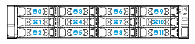
Figure 24 Drive numbering for the 12LFF+2SFF drive configuration (12LFF server)
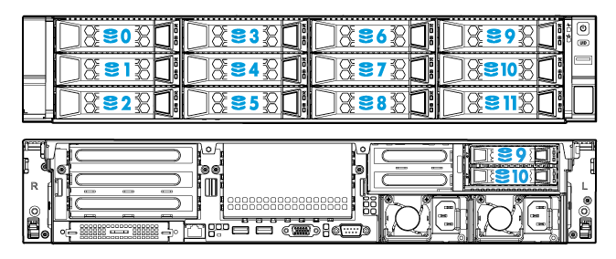
Figure 25 Drive numbering for the 12LFF+4SFF drive configuration (12LFF server)
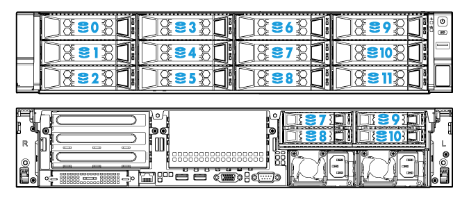
Figure 26 Drive numbering for the 14LFF (12 front+2 rear) drive configuration (12LFF server)
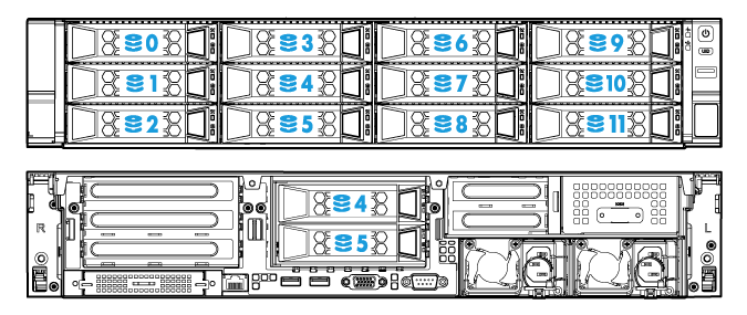
Figure 27 Drive numbering for the 16LFF (12 front+4 rear) drive configuration (12LFF server)
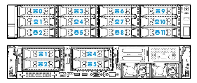
Figure 28 Drive numbering for the 14LFF (12 front+2 rear)+2SFF drive configuration (12LFF server)
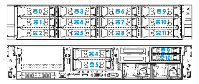
Figure 29 Drive numbering for the 14LFF (12 front+2 rear)+4SFF drive configuration (12LFF server)
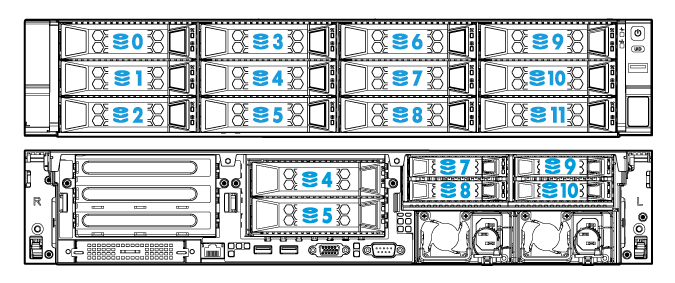
Figure 30 Drive numbering for the 16LFF (12 front+4 rear)+2SFF drive configuration (12LFF server)
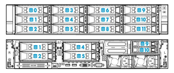
Figure 31 Drive numbering for the 16LFF (12 front+4 rear)+4SFF drive configuration (12LFF server)
PCIe modules
Typically, the PCIe modules are available in the following standard form factors:
· LP—Low profile.
· FHHL—Full height and half length.
· FHFL—Full height and full length.
· HHHL—Half height and half length.
· HHFL—Half height and full length.
Some PCIe modules, such as mezzanine storage controllers, are in non-standard form factors.
Storage controllers
The server supports the following types of storage controllers depending on their form factors:
· Embedded RAID controller—Embedded in the server and does not require installation.
· Mezzanine storage controller—Installed on the Mezzanine storage controller connector of the system board and does not require a riser card for installation.
· Standard storage controller—Comes in a standard PCIe form factor and typically requires a riser card for installation.
For some storage controllers, you can order a power fail safeguard module to prevent data loss from power outages. This module provides a flash card and a supercapacitor. When a system power failure occurs, the supercapacitor provides power for a minimum of 20 seconds. During this interval, the storage controller can transfer data from DDR memory to the flash card, where the data remains indefinitely or until the controller retrieves the data. If the storage controller contains a built-in flash card, you can order only a supercapacitor.
Embedded RSTe RAID controller
|
Item |
Specifications |
|
Type |
Embedded in PCH of the system board |
|
Connectors |
· One onboard ×8 mini-SAS connector · One onboard ×1 SATA connector |
|
Number of internal ports |
9 internal SATA ports |
|
Drive interface |
6 Gbps SATA 3.0 |
|
PCIe interface |
PCIe2.0 ×4 |
|
RAID levels |
0, 1, 5, 10 |
|
Built-in cache memory |
N/A |
|
Supported drives |
· SATA HDD · SATA SSD |
|
Power fail safeguard module |
Not supported |
|
Firmware upgrade |
Upgraded with the BIOS |
Mezzanine and standard storage controllers
For more information, visit the query tool at http://www.h3c.com/cn/Service/Document_Software/Document_Center/Server/.
GPU modules
GPU module and riser card compatibility
|
Riser card |
PCIe riser connector |
PCIe slot |
Available GPU modules |
|
RC-GPU/FHHL-2U-G3-1 |
Connector 1 or 2 |
Slot 2 or 5 |
· GPU-M4-1 · GPU-M4000-1-X · GPU-K80-1 · GPU-M60-1-X · GPU-P4-X · GPU-T4 · GPU-M2000 · GPU-P40-X · GPU-M10-X · GPU-MLU100-D3 · GPU-MLU270-S4 |
|
Slot 3 or 6 |
Not supported |
||
|
RC-GPU/FHHL-2U-G3-2 |
Connector 3 |
Slot 7 |
· GPU-M4-1 · GPU-M4000-1-X · GPU-K80-1 · GPU-M60-1-X · GPU-P4-X · GPU-M2000 · GPU-P40-X · GPU-M10-X |
|
Slot 8 |
Not supported |
||
|
RC-2*FHFL-2U-G3 |
Connector 1 |
Slot 1 |
· GPU-M4-1 · GPU-M4000-1-X · GPU-P4-X · GPU-T4 · GPU-M2000 · GPU-MLU100-D3 · GPU-MLU270-S4 |
|
Slot 2 |
· GPU-M4-1 · GPU-M4000-1-X · GPU-P4-X · GPU-T4 · GPU-M2000 · GPU-MLU100-D3 · GPU-MLU270-S4 |
||
|
RC-FHHL-2U-G3-1 |
Connector 1 or 2 |
Slot 2 or 5 |
· GPU-P100 · GPU-V100-32G · GPU-V100 · GPU-V100S-32G · GPU-RTX6000 |
|
Slot 3 or 6 |
Not supported |
||
|
RC-3GPU-R4900-G3 |
Connector 1 or 2 |
Slot 1 or 4 |
· GPU-P4-X · GPU-T4 · GPU-MLU100-D3 |
|
Slot 2 or 5 |
|||
|
Slot 3 or 6 |
|||
|
RC-FHHL-2U-G3-2 |
Connector 3 |
Slot 7 |
· GPU-P100 · GPU-V100-32G · GPU-V100 · GPU-V100S-32G · GPU-RTX6000 |
|
Slot 8 |
Not supported |
||
|
RC-2GPU-R4900-G3 |
Connector 3 |
Slot 7 |
· GPU-P4-X · GPU-T4 · GPU-MLU100-D3 |
|
Slot 8 |
Riser cards
Riser card guidelines
Each PCIe slot in a riser card can supply a maximum of 75 W power to the PCIe module. You must connect a separate power cord to the PCIe module only if it requires more than 75 W power.
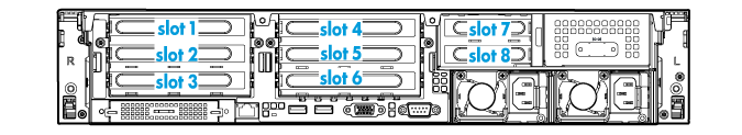
PCIe slot numbering
The server provides a maximum of eight PCIe slots, as shown in Figure 32.
Figure 32 PCIe slots at the rear panel
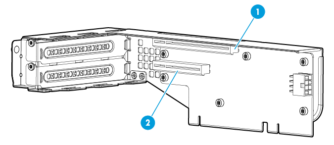
Riser cards for riser connector 1 or 2
If a riser card can be installed on riser connector 1 or 2, the slot numbers of its PCIe slots are presented in the m/n format in this document.
· The m argument represents the PCIe slot number on connector 1.
· The n argument represents the PCIe slot number on connector 2.
For example, PCIe slot 2/5 represents that a PCIe slot is numbered 2 or 5 when the riser card is installed on riser connector 1 or riser connector 2, respectively.
RC-2*FHFL-2U-G3
The riser card must be used together with a RC-Mezz-Riser-G3 PCIe riser card.
|
Item |
Specifications |
|
PCIe riser connector |
Connector 1 |
|
PCIe slots |
· Slot 1, PCIe3.0 ×16 (16, 8, 4, 2, 1) · Slot 2, PCIe3.0 ×16 (16, 8, 4, 2, 1) NOTE: The numbers in parentheses represent link widths. Both slots support single-slot wide GPU modules. |
|
Form factors of PCIe modules |
FHFL |
|
Maximum power supplied per PCIe slot |
75 W |
Figure 33 PCIe slots on the RC-2*FHFL-2U-G3 riser card
|
(1) PCIe slot 1 |
(2) PCIe slot 2 |
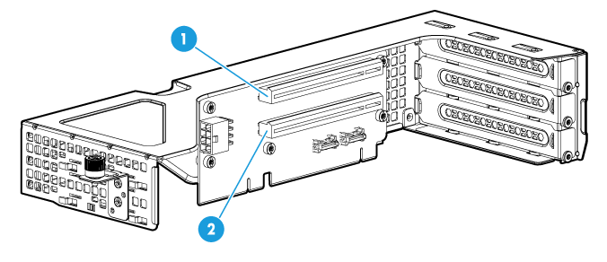
RC-3GPU-R4900-G3
|
Item |
Specifications |
|
PCIe riser connector |
· Connector 1 · Connector 2 |
|
PCIe slots |
· Slot 1/4, PCIe3.0 ×16 (8, 4, 2, 1) · Slot 2/5, PCIe3.0 ×16 (8, 4, 2, 1) · Slot 3/6, PCIe3.0 ×8 (8, 4, 2, 1) NOTE: The numbers in parentheses represent link widths. |
|
Available PCIe modules |
GPU-P4-X, GPU-T4, and GPU-MLU100-D3 GPU modules |
|
Maximum power supplied per PCIe slot |
75 W |
Figure 34 PCIe slots on the RC-3GPU-R4900-G3 riser card
|
(1) PCIe slot 1/4 |
(2) PCIe slot 2/5 |
(3) PCIe slot 3/6 |
RC-FHHL-2U-G3-1
|
Item |
Specifications |
|
PCIe riser connector |
· Connector 1 · Connector 2 |
|
PCIe slots |
· Slot 2/5: PCIe3.0 ×16 (16, 8, 4, 2, 1) · Slot 3/6: PCIe3.0 ×8 (8, 4, 2, 1) NOTE: The numbers in parentheses represent link widths. |
|
Form factors of PCIe modules |
FHHL |
|
Maximum power supplied per PCIe slot |
75 W |
Figure 35 PCIe slots on the RC-FHHL-2U-G3-1 riser card
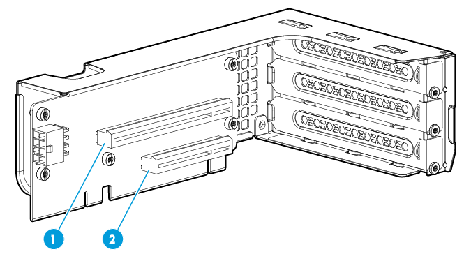
|
(1) PCIe slot 2/5 |
(2) PCIe slot 3/6 |
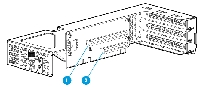
RC-FHHL/NVMe-2U-G3-1
|
Item |
Specifications |
|
PCIe riser connector |
· Connector 1 · Connector 2 |
|
PCIe slots |
· Slot 1/4: PCIe3.0 ×16 (8, 4, 2, 1) NOTE: The numbers in parentheses represent link widths. |
|
Form factors of PCIe modules |
FHHL |
|
Maximum power supplied per PCIe slot |
75 W |
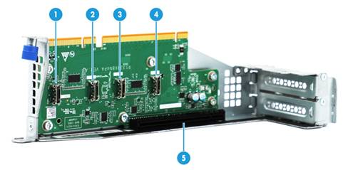
Figure 36 PCIe slots on the RC-FHHL/NVMe-2U-G3-1 riser card
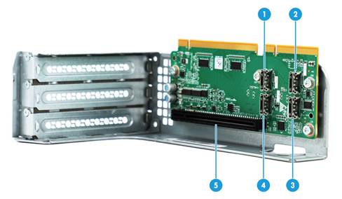
|
(1) NVMe connector 3 |
(2) NVMe connector 1 |
|
(3) NVMe connector 2 |
(4) NVMe connector 4 |
|
(5) PCIe slot 1/4 |
|
RC-GPU/FHHL-2U-G3-1
|
Item |
Specifications |
|
PCIe riser connector |
· Connector 1 · Connector 2 |
|
PCIe slots |
· Slot 2/5, PCIe3.0 ×16 (16, 8, 4, 2, 1) · Slot 3/6, PCIe3.0 ×8 (8, 4, 2, 1) NOTE: The numbers in parentheses represent link widths. |
|
Form factors of PCIe modules |
FHHL (only slot 2/5 supports single-wide and double-wide GPU modules) |
|
Maximum power supplied per PCIe slot |
75 W |
Figure 37 PCIe slots on the RC-GPU/FHHL-2U-G3-1 riser card
|
(1) PCIe slot 2/5 |
(2) PCIe slot 3/6 |
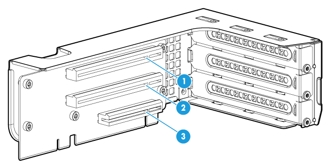
RS-3*FHHL-R4900
|
Item |
Specifications |
|
PCIe riser connector |
· Connector 1 · Connector 2 |
|
PCIe slots |
· Slot 1/4, PCIe3.0 ×16 (8, 4, 2, 1) · Slot 2/5, PCIe3.0 ×16 (8, 4, 2, 1) · Slot 3/6, PCIe3.0 ×8 (8, 4, 2, 1) NOTE: The numbers in parentheses represent link widths. |
|
Form factors of PCIe modules |
FHHL |
|
Maximum power supplied per PCIe slot |
75 W |
Figure 38 PCIe slots on the RS-3*FHHL-R4900 riser card
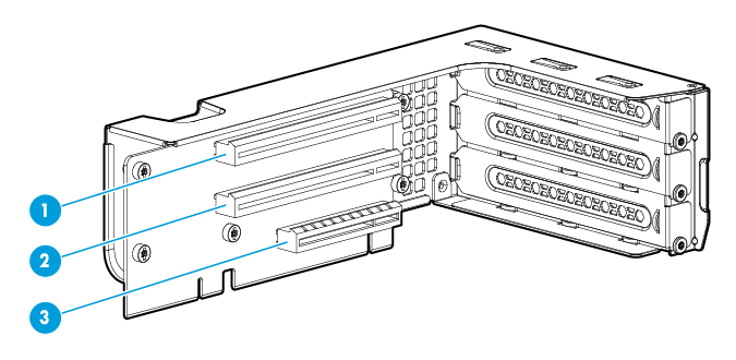
|
(1) PCIe slot 1/4 |
(2) PCIe slot 2/5 |
(3) PCIe slot 3/6 |
Riser cards for riser connector 3
RC-2*LP-2U-G3
|
Item |
Specifications |
|
PCIe riser connector |
Connector 3 |
|
PCIe slots |
· Slot 7, PCIe3.0 ×16 (16, 8, 4, 2, 1) · Slot 8, PCIe3.0 ×8 (8, 4, 2, 1) NOTE: The numbers in parentheses represent link widths. |
|
Form factors of PCIe modules |
LP |
|
Maximum power supplied per PCIe slot |
75 W |
Figure 39 PCIe slots on the RC-2*LP-2U-G3 riser card
|
(1) PCIe slot 7 |
(2) PCIe slot 8 |
RC-2GPU-R4900-G3
|
Item |
Specifications |
|
PCIe riser connector |
Connector 3 |
|
PCIe slots |
· Slot 7: PCIe3.0 ×16 (16, 8, 4, 2, 1) · Slot 8: PCIe3.0 ×8 (8, 4, 2, 1) NOTE: The numbers in parentheses represent link widths. |
|
Available PCIe modules |
GPU-P4-X, GPU-T4, and GPU-MLU100-D3 GPU modules |
|
Maximum power supplied per PCIe slot |
75 W |
Figure 40 PCIe slots on the RC-2GPU-R4900-G3 riser card
|
(1) PCIe slot 7 |
(2) PCIe slot 8 |
RC-FHHL-2U-G3-2
|
Item |
Specifications |
|
PCIe riser connector |
Connector 3 |
|
PCIe slots |
· Slot 7, PCIe3.0 ×16 (16, 8, 4, 2, 1) · Slot 8, PCIe3.0 ×8 (8, 4, 2, 1) NOTE: The numbers in parentheses represent link widths. |
|
Form factors of PCIe modules |
FHHL |
|
Maximum power supplied per PCIe slot |
75 W |
Figure 41 PCIe slots on the RC-FHHL-2U-G3-2 riser card
|
(1) PCIe slot 7 |
(2) PCIe slot 8 |
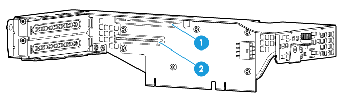
RC-GPU/FHHL-2U-G3-2
|
Item |
Specifications |
|
PCIe riser connector |
Connector 3 |
|
PCIe slots |
· Slot 7: PCIe3.0 ×16 (16, 8, 4, 2, 1) · Slot 8: PCIe3.0 ×8 (8, 4, 2, 1) NOTE: The numbers in parentheses represent link widths. |
|
Form factors of PCIe modules |
· Slot 7: FHFL (including single-wide and double-wide GPU modules) · Slot 8: FHHL |
|
Maximum power supplied per PCIe slot |
75 W |
Figure 42 PCIe slots on the RC-GPU/FHHL-2U-G3-2 riser card
|
(1) PCIe slot 7 |
(2) PCIe slot 8 |
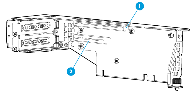
RC-HHHL/NVMe-2U-G3-2
|
Item |
Specifications |
|
PCIe riser connector |
Connector 3 |
|
PCIe slots |
Slot 7, PCIe3.0 ×16 (8, 4, 2, 1) NOTE: The numbers in parentheses represent link widths. |
|
Form factors of PCIe modules |
LP |
|
Maximum power supplied per PCIe slot |
75 W |
Figure 43 PCIe slots on the RC-HHHL/NVMe-2U-G3-2 riser card
|
(1) NVMe connector 1 |
(2) NVMe connector 2 |
|
(3) NVMe connector 3 |
(4) NVMe connector 4 |
|
(5) PCIe slot 7 |
|
Fans
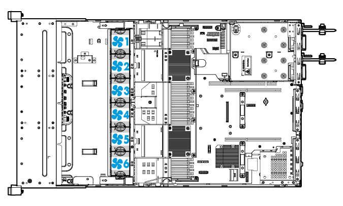
Fan layout
The server supports a maximum of six hot swappable fans. Figure 44 shows the layout of the fans in the chassis.
Power supplies
The power supplies have an overtemperature protection mechanism. A power supply stops working when an overtemperature occurs and automatically recovers when the overtemperature condition is removed.
550 W Platinum power supply (PSR550-12A, PSR550-12A-1, and PSR550-12A-2)
|
Item |
Specifications |
|
Model |
· PSR550-12A · PSR550-12A-1 · PSR550-12A-2 |
|
Rated input voltage range |
· 100 VAC to 240 VAC @ 50/60 Hz (10 A receptacle) · 192 VDC to 288 VDC (240 HVDC power source) |
|
Maximum rated input current |
· 8.0 A @ 100 VAC to 240 VAC · 2.75 A @ 240 VDC |
|
Maximum rated output power |
550 W |
|
Efficiency at 50 % load |
94%, 80 Plus Platinum level |
|
Temperature requirements |
· Operating temperature: 0°C to 50°C (32°F to 122°F) · Storage temperature: –40°C to +70°C (–40°F to +158°F) |
|
Operating humidity |
5% to 90% |
|
Maximum altitude |
5000 m (16404.20 ft) |
|
Redundancy |
1+1 redundancy |
|
Hot swappable |
Yes |
|
Cold backup |
Yes |
550 W Platinum power supply (PS-2551-9L3)
|
Item |
Specifications |
|
Model |
PS-2551-9L3 |
|
Rated input voltage range |
· 100 VAC to 240 VAC @ 50/60 Hz · 192 VDC to 288 VDC (240 HVDC power source) |
|
Maximum rated input current |
· 6.5 A @ 100 VAC to 240 VAC · 3.6 A @ 240 VDC |
|
Maximum rated output power |
550 W |
|
Efficiency at 50 % load |
94%, 80 Plus Platinum level |
|
Temperature requirements |
· Operating temperature: 0°C to 55°C (32°F to 131°F) · Storage temperature: –40°C to +85°C (–40°F to +185°F) |
|
Operating humidity |
5% to 85% |
|
Maximum altitude |
5000 m (16404.20 ft) |
|
Redundancy |
1+1 redundancy |
|
Hot swappable |
Yes |
|
Cold backup |
Yes |
550 W Platinum power supply (GW-CRPS550N)
|
Item |
Specifications |
|
Model |
GW-CRPS550N |
|
Rated input voltage range |
· 100 VAC to 240 VAC @ 50/60 Hz · 192 VDC to 288 VDC (240 HVDC power source) |
|
Maximum rated input current |
· 7 A @ 100 VAC to 240 VAC · 3.5 A @ 240 VDC |
|
Maximum rated output power |
550 W |
|
Efficiency at 50 % load |
94%, 80 Plus Platinum level |
|
Temperature requirements |
· Operating temperature: 0°C to 50°C (32°F to 122°F) · Storage temperature: –40°C to +70°C (–40°F to +158°F) |
|
Operating humidity |
5% to 85% |
|
Maximum altitude |
5000 m (16404.20 ft) |
|
Redundancy |
1+1 redundancy |
|
Hot swappable |
Yes |
|
Cold backup |
Yes |
550 W high-efficiency Platinum power supply
|
Item |
Specifications |
|
Model |
DPS-550W-12A |
|
Rated input voltage range |
· 100 VAC to 240 VAC @ 50/60 Hz (10 A receptacle) · 192 VDC to 288 VDC (240 HVDC power source) |
|
Maximum rated input current |
· 7.1 A @ 100 VAC to 240 VAC · 2.8 A @ 240 VDC |
|
Maximum rated output power |
550 W |
|
Efficiency at 50 % load |
94%, 80 Plus Platinum level |
|
Temperature requirements |
· Operating temperature: 0°C to 55°C (32°F to 131°F) · Storage temperature: –40°C to +70°C (–40°F to +158°F) |
|
Operating humidity |
5% to 85% |
|
Maximum altitude |
5000 m (16404.20 ft) |
|
Redundancy |
1+1 redundancy |
|
Hot swappable |
Yes |
|
Cold backup |
Yes |
800 W Platinum power supply (PSR800-12A)
|
Item |
Specifications |
|
Model |
PSR800-12A |
|
Rated input voltage range |
· 100 VAC to 240 VAC @ 50/60 Hz (10 A receptacle) · 192 VDC to 288 VDC (240 HVDC power source) |
|
Maximum rated input current |
· 10.0 A @ 100 VAC to 240 VAC · 4.0 A @ 240 VDC |
|
Maximum rated output power |
800 W |
|
Efficiency at 50 % load |
|
|
Temperature requirements |
· Operating temperature: 0°C to 50°C (32°F to 122°F) · Storage temperature: –40°C to +70°C (–40°F to +158°F) |
|
Operating humidity |
5% to 90% |
|
Maximum altitude |
5000 m (16404.20 ft) |
|
Redundancy |
1+1 redundancy |
|
Hot swappable |
Yes |
|
Cold backup |
Yes |
800 W Platinum power supply (PS-2801-9L3)
|
Item |
Specifications |
|
Model |
PS-2801-9L3 |
|
Rated input voltage range |
· 100 VAC to 240 VAC @ 50/60 Hz · 192 VDC to 288 VDC (240 HVDC power source) |
|
Maximum rated input current |
· 10.0 A @ 100 VAC to 240 VAC · 4.5 A @ 240 VDC |
|
Maximum rated output power |
800 W |
|
Efficiency at 50 % load |
94%, 80 Plus Platinum level |
|
Temperature requirements |
· Operating temperature: 0°C to 55°C (32°F to 131°F) · Storage temperature: –40°C to +85°C (–40°F to +185°F) |
|
Operating humidity |
5% to 85% |
|
Maximum altitude |
5000 m (16404.20 ft) |
|
Redundancy |
1+1 redundancy |
|
Hot swappable |
Yes |
|
Cold backup |
Yes |
800 W Platinum power supply (GW-CRPS800B)
|
Item |
Specifications |
|
Model |
GW-CRPS800B |
|
Rated input voltage range |
· 100 VAC to 240 VAC @ 50/60 Hz · 192 VDC to 288 VDC (240 HVDC power source) |
|
Maximum rated input current |
· 10.0 A @ 100 VAC to 240 VAC · 5.0 A @ 240 VDC |
|
Maximum rated output power |
800 W |
|
Efficiency at 50 % load |
94%, 80 Plus Platinum level |
|
Temperature requirements |
· Operating temperature: 0°C to 55°C (32°F to 131°F) · Storage temperature: –40°C to +70°C (–40°F to +158°F) |
|
Operating humidity |
5% to 85% |
|
Maximum altitude |
5000 m (16404.20 ft) |
|
Redundancy |
1+1 redundancy |
|
Hot swappable |
Yes |
|
Cold backup |
Yes |
800 W –48 VDC power supply
|
Item |
Specifications |
|
Model |
DPS-800W-12A-48V |
|
Rated input voltage range |
–48 VDC to –60 VDC |
|
Maximum rated input current |
20.0 A @ –48 VDC to –60 VDC |
|
Maximum rated output power |
800 W |
|
Efficiency at 50 % load |
92% |
|
Temperature requirements |
· Operating temperature: 0°C to 55°C (32°F to 131°F) · Storage temperature: –40°C to +70°C (–40°F to +158°F) |
|
Operating humidity |
5% to 90% |
|
Maximum altitude |
5000 m (16404.20 ft) |
|
Redundancy |
1+1 redundancy |
|
Hot swappable |
Yes |
|
Cold backup |
Yes |
800 W 336 V high-voltage DC power supply
|
Item |
Specifications |
|
Model |
PSR800-12AHD |
|
Rated input voltage range |
· 100 VAC to 240 VAC @ 50/60 Hz (10 A receptacle) · 180 VDC to 400 VDC (240 to 336 HVDC power source) |
|
Maximum rated input current |
· 10.0 A @ 100 VAC to 240 VAC · 3.8 A @ 240 VDC |
|
Maximum rated output power |
800 W |
|
Efficiency at 50 % load |
94% |
|
Temperature requirements |
· Operating temperature: 0°C to 50°C (32°F to 122°F) · Storage temperature: –40°C to +70°C (–40°F to +158°F) |
|
Operating humidity |
5% to 90% |
|
Maximum altitude |
5000 m (16404.20 ft) |
|
Redundancy |
1+1 redundancy |
|
Hot swappable |
Yes |
|
Cold backup |
Yes |
850 W high-efficiency Platinum power supply
|
Item |
Specifications |
|
Model |
DPS-850W-12A |
|
Rated input voltage range |
· 100 VAC to 240 VAC @ 50/60 Hz (10 A receptacle) · 192 VDC to 288 VDC (240 HVDC power source) |
|
Maximum rated input current |
· 10.0 A @ 100 VAC to 240 VAC · 4.4 A @ 240 VDC |
|
Maximum rated output power |
850 W |
|
Efficiency at 50 % load |
94%, 80 Plus Platinum level |
|
Temperature requirements |
· Operating temperature: 0°C to 55°C (32°F to 131°F) · Storage temperature: –40°C to +70°C (–40°F to +158°F) |
|
Operating humidity |
5% to 85% |
|
Maximum altitude |
5000 m (16404.20 ft) |
|
Redundancy |
1+1 redundancy |
|
Hot swappable |
Yes |
|
Cold backup |
Yes |
850 W Titanium power supply
|
Item |
Specifications |
|
Model |
PSR850-12A |
|
Rated input voltage range |
· 100 VAC to 240 VAC @ 50/60 Hz (10 A receptacle) · 192 VDC to 288 VDC (240 HVDC power source) |
|
Maximum rated input current |
· 11.0 A @ 100 VAC to 240 VAC · 4.0 A @ 240 VDC |
|
Maximum rated output power |
850 W |
|
Efficiency at 50 % load |
96%, 80 Plus Titanium level |
|
Temperature requirements |
· Operating temperature: 0°C to 50°C (32°F to 122°F) · Storage temperature: –40°C to +70°C (–40°F to +158°F) |
|
Operating humidity |
5% to 85% |
|
Maximum altitude |
5000 m (16404.20 ft) |
|
Redundancy |
1+1 redundancy |
|
Hot swappable |
Yes |
|
Cold backup |
Yes |
1200 W Platinum power supply
|
Item |
Specifications |
|
Model |
PSR1200-12A |
|
Rated input voltage range |
· 100 VAC to 127 VAC @ 50/60 Hz (1000 W) · 200 VAC to 240 VAC @ 50/60 Hz (1200 W) · 192 VDC to 288 VDC (1200 W) |
|
Maximum rated input current |
· 12.0 A @ 100 VAC to 240 VAC · 6.0 A @ 240 VDC |
|
Maximum rated output power |
1200 W |
|
Efficiency at 50 % load |
94%, 80 Plus Platinum level |
|
Temperature requirements |
· Operating temperature: 0°C to 50°C (32°F to 122°F) · Storage temperature: –40°C to +70°C (–40°F to +158°F) |
|
Operating humidity |
5% to 90% |
|
Maximum altitude |
5000 m (16404.20 ft) |
|
Redundancy |
1+1 redundancy |
|
Hot swappable |
Yes |
|
Cold backup |
Yes |
1300 W Platinum power supply
|
Item |
Specifications |
|
Model |
DPS-1300AB-6 R |
|
Rated input voltage range |
· 100 VAC to 127 VAC @ 50/60 Hz (1000 W) · 200 VAC to 240 VAC @ 50/60 Hz (1300 W) · 192 VDC to 288 VDC (240 HVDC power supply)(1300 W) |
|
Maximum rated input current |
· 13.8 A @ 100 VAC to 127 VAC · 8.5 A @ 200 to 240 VAC |
|
Maximum rated output power |
1300 W |
|
Efficiency at 50 % load |
94%, 80 Plus Platinum level |
|
Temperature requirements |
· Operating temperature: 0°C to 55°C (32°F to 131°F) · Storage temperature: –40°C to +70°C (–40°F to +158°F) |
|
Operating humidity |
5% to 85% |
|
Maximum altitude |
5000 m (16404.20 ft) |
|
Redundancy |
1+1 redundancy |
|
Hot swappable |
Yes |
|
Cold backup |
Yes |
1600 W Platinum power supply
|
Item |
Specifications |
|
Model |
DPS-1600AB-13 R |
|
Rated input voltage range |
· 100 VAC to 127 VAC @ 50/60 Hz (1000 W) · 200 VAC to 240 VAC @ 50/60 Hz (1600 W) · 192 VDC to 288 VDC (240 HVDC power supply)(1600 W) |
|
Maximum rated input current |
· 13.8 A @ 100 VAC to 127 VAC · 9.6 A @ 200 to 240 VAC |
|
Maximum rated output power |
1600 W |
|
Efficiency at 50 % load |
94%, 80 Plus Platinum level |
|
Temperature requirements |
· Operating temperature: 0°C to 55°C (32°F to 131°F) · Storage temperature: –40°C to +70°C (–40°F to +158°F) |
|
Operating humidity |
5% to 85% |
|
Maximum altitude |
5000 m (16404.20 ft) |
|
Redundancy |
1+1 redundancy |
|
Hot swappable |
Yes |
|
Cold backup |
Yes |
B/D/F information
Viewing B/D/F information
Table 2 lists the default Bus/Device/Function numbers (B/D/F) for the scenario where all the following conditions are met:
· All processors are installed.
· All PCIe riser connectors are installed with riser cards.
· All PCIe slots in riser cards are installed with PCIe modules.
· An mLOM network adapter is installed in slot 11.
· A Mezzanine storage controller is installed in slot 10.
B/D/F information in Table 2 might change if any of the above conditions is not met or a PCIe module with a PCIe bridge is installed.
For more information about riser cards, see "Riser cards." For more information the locations of slot 9 and slot 11, see "System board."
For information about how to obtain B/D/F information, see "Obtaining B/D/F information."
Table 18 PCIe modules and the corresponding Bus/Device/Function numbers
|
Riser card model |
PCIe riser connector |
PCIe slot |
Processor |
Port number |
Root port (B/D/F) |
End point (B/D/F) |
|
RC-2*FHFL-2U-G3 |
Connector 1 |
slot 1 |
Processor 1 |
Port 3A |
5d:00.00 |
5e:00.00 |
|
slot 2 |
Processor 1 |
Port 1A |
17:00.00 |
18:00.00 |
||
|
RS-3*FHHL-R4900 RC-3GPU-R4900-G3 |
Connector 1 |
slot 1 |
Processor 1 |
Port 3C |
5d:02.00 |
5f:00.00 |
|
slot 2 |
Processor 1 |
Port 1A |
17:00.00 |
18:00.00 |
||
|
slot 3 |
Processor 1 |
Port 1C |
17:02.00 |
19:00.00 |
||
|
Connector 2 |
slot 4 |
Processor 2 |
Port 1A |
85:00.00 |
86:00.00 |
|
|
slot 5 |
Processor 2 |
Port 2A |
ae:00.00 |
af:00.00 |
||
|
slot 6 |
Processor 2 |
Port 2C |
ae:02.00 |
b0:00.00 |
||
|
RC-FHHL/NVMe-2U-G3-1 |
Connector 1 |
slot 1 |
Processor 1 |
Port 3C |
5d:02.00 |
5f:00.00 |
|
Connector 2 |
slot 4 |
Processor 2 |
Port 1A |
85:00.00 |
86:00.00 |
|
|
RC-FHHL-2U-G3-1 RC-FHHL-2U-G3-1 |
Connector 1 |
slot 2 |
Processor 1 |
Port 1A |
17:00.00 |
18:00.00 |
|
slot 3 |
Processor 1 |
Port 3C |
5d:02.00 |
5f:00.00 |
||
|
Connector 2 |
slot 5 |
Processor 2 |
Port 2A |
ae:00.00 |
af:00.00 |
|
|
slot 6 |
Processor 2 |
Port 1A |
85:00.00 |
86:00.00 |
||
|
RC-FHHL-2U-G3-2 RC-2*LP-2U-G3 RC-GPU/FHHL-2U-G3-2 RC-2GPU-R4900-G3 |
Connector 3 |
slot 7 |
Processor 2 |
Port 3A |
d7:00.00 |
d8:00.00 |
|
slot 8 |
Processor 2 |
Port 1C |
85:02.00 |
87:00.00 |
||
|
RC-HHHL/NVMe-2U-G3-2 |
Connector 3 |
slot 7 |
Processor 2 |
Port 1C |
85:02.00 |
87:00.00 |
|
N/A |
N/A |
slot 11 (for sLOM network adapter) |
Processor 1 |
Port 2A |
3a:00.00 |
3d:00.00 |
|
N/A |
N/A |
slot 11 (for Mezzanine storage controller) |
Processor 1 |
Port 3A |
5d:00.00 |
5e:00.00 |
|
|
NOTE: · The root port (B/D/F) indicates the bus number of the PCIe root node in the processor. · The end point (B/D/F) indicates the bus number of a PCIe module in the operating system. |
Obtaining B/D/F information
You can obtain B/D/F information by using one of the following methods:
· BIOS log—Search the dumpiio keyword in the BIOS log.
· UEFI shell—Execute the pci command. For information about how to execute the command, execute the help pci command.
· Operating system—The obtaining method varies by OS.
¡ For Linux, execute the lspci command.
If Linux does not support the lspci command by default, you must execute the yum command to install the pci-utils package.
¡ For Windows, install the pciutils package, and then execute the lspci command.
¡ For VMware, execute the lspci command.
Diagnostic panels
Diagnostic panels provide diagnostics and troubleshooting capabilities. You can locate and troubleshoot component failures by using the diagnostic panels in conjunction with the event log generated in HDM.
|
|
NOTE: A diagnostic panel displays only one component failure at a time. When multiple component failures exist, the diagnostic panel displays all these failures one by one at intervals of 4 seconds. |
Diagnostic panel specifications
|
Model |
Specifications |
|
SD-SFF-A |
SFF diagnostic panel for the 25SFF server |
|
SD-SFF-B |
SFF diagnostic panel for the 8SFF server |
|
SD-LFF-G3-A |
LFF diagnostic panel for the LFF servers |
Diagnostic panel view
Figure 45 shows the error code and LEDs on a diagnostic panel.
Figure 45 Diagnostic panel view
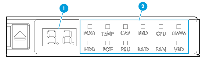
|
(1) Error code |
(2) LEDs |
For more information about the LEDs and error codes, see "LEDs."
LEDs
POST LED
|
LED status |
Error code |
Description |
|
Steady green |
Code for the current POST phase (in the range of 00 to 99) |
The server is performing POST without detecting any error. |
|
Flashing red (1 Hz) |
The POST process encountered an error and stopped in the displayed phase. |
|
|
Off |
00 |
The server is operating correctly when the error code is 00 and all LEDs are off. |
TEMP LED
|
LED status |
Error code |
Description |
|
Flashing amber (1 Hz) |
Temperature sensor ID |
A major temperature alarm is present on the component monitoried by the sensor. This alarm might occur if the temperature of the component exceeds the upper major threshold or drops below the lower major threshold. |
|
Flashing red (1 Hz) |
Temperature sensor ID |
A critical temperature alarm is present on the component monitoried by the sensor. This alarm might occur if the temperature of the component exceeds the upper critical threshold or drops below the lower critical threshold. |
CAP LED
|
LED status |
Error code |
Description |
|
Flashing amber |
01 |
The system power consumption has exceeded the power cap value. |
Component LEDs
An alarm is present if a component LED has one of the following behaviors:
· Flashing amber (1 Hz)—A major alarm has occurred.
· Flashing red (1 Hz)—A critical alarm has occurred.
Use Table 3 to identify the faulty item if a component LED has one of those behaviors. To obtain records of component status changes, use the event log in HDM. For information about using the event log, see HDM online help.
Table 19 LED, error code and faulty item matrix
|
LED |
Error code |
Faulty item |
|
BRD |
11 |
System board |
|
21 |
· Drive backplane in bay 1 (8SFF server) · Front backplane (non-8SFF servers) |
|
|
22 |
Drive backplane in drive cage bay 2 (8SFF server) |
|
|
23 |
Drive backplane in drive cage bay 3 (8SFF server) |
|
|
31 |
Rear 2LFF/4LFF drive backplane |
|
|
32 |
Rear 2SFF/4SFF drive backplane |
|
|
71 |
Mezzanine storage controller |
|
|
81 |
Reserved |
|
|
91 |
mLOM network adapter |
|
|
NOTE: If the error code field displays 11 and any other code alternatively, replace the faulty item other than the system board. If the issue persists, replace the system board. |
||
|
CPU (processor) |
01 |
Processor 1 |
|
02 |
Processor 2 |
|
|
DIMM |
A1 through A9, AA, AC, or AE |
· A1 through A9—DIMMs in slots A1 through A9 · AA—DIMM in slot A10 · AC—DIMM in slot A11 · AE—DIMM in slot A12 |
|
b1 through b9, bA, bC, or bE |
· b1 through b9—DIMMs in slots B1 through B9 · bA—DIMM in slot B10 · bC—DIMM in slot B11 · bE—DIMM in slot B12 |
|
|
HDD |
00 through 07 |
Relevant front drive (8LFF server) |
|
10 through 17 |
Relevant drive in bay 1 (8SFF server) |
|
|
20 through 27 |
Relevant drive in bay 2 (8SFF server) |
|
|
30 through 37 |
Relevant drive in bay 3 (8SFF server) |
|
|
00 through 11 |
Relevant front drive (12LFF server) |
|
|
20 through 29 |
Relevant rear drive (12LFF server) |
|
|
00 through 24 |
Relevant front drive (25SFF server) |
|
|
30 through 39 |
Relevant rear drive (25SFF server) |
|
|
PCIE |
01 through 08 |
PCIe modules in PCIe slots 1 to 8 of the riser card |
|
PSU |
01 |
Power supply 1 |
|
02 |
Power supply 2 |
|
|
RAID |
10 |
Mezzanine storage controller |
|
FAN |
01 through 06 |
Fan 1 through Fan 6 |
|
VRD |
01 |
System board P5V voltage |
|
02 |
System board P1V05 PCH voltage |
|
|
03 |
System board PVCC HPMOS voltage |
|
|
04 |
System board P3V3 voltage |
|
|
05 |
System board P1V8 PCH voltage |
|
|
06 |
System board PVCCIO processor 1 voltage |
|
|
07 |
System board PVCCIN processor 1 voltage |
|
|
08 |
System board PVCCIO processor 2 voltage |
|
|
09 |
System board PVCCIN processor 2 voltage |
|
|
10 |
System board VPP processor 1 ABC voltage |
|
|
11 |
System board VPP processor 1 DEF voltage |
|
|
12 |
System board VDDQ processor 1 ABC voltage |
|
|
13 |
System board VDDQ processor 1 DEF voltage |
|
|
14 |
System board VTT processor 1 ABC voltage |
|
|
15 |
System board VTT processor 1 DEF voltage |
|
|
16 |
System board VPP processor 2 ABC voltage |
|
|
17 |
System board VPP processor 2 DEF voltage |
|
|
18 |
System board VDDQ processor 2 ABC voltage |
|
|
19 |
System board VDDQ processor 2 DEF voltage |
|
|
20 |
System board VTT processor 2 ABC voltage |
|
|
21 |
System board VTT processor 2 DEF voltage |
|
|
22 |
System board P5V_STBY power supply |
|
|
23 |
System board P1V8_PCH_STBY power supply |
|
|
24 |
System board PVNN_PCH_STBY power supply |
|
|
25 |
System board P1V05_PCH_STBY power supply |
|
|
27 |
System board CPU1_PVCCSA power supply |
|
|
28 |
System board CPU1_P1V0 power supply |
|
|
29 |
System board CPU1_PVMMCP power supply |
|
|
30 |
System board CPU2_PVCCSA power supply |
|
|
31 |
System board CPU2_P1V0 power supply |
|
|
32 |
System board CPU2_PVMMCP power supply |
|
|
40 |
mLOM network adapter power supply |
|
|
41 |
Dual SD card extended module power supply |
|
|
42 |
Power supply to the drive backplane of drive cage bay 3 |
|
|
43 |
Power supply to the drive backplane of drive cage bay 2 |
|
|
44 |
· 8SFF configuration: Power supply to the drive backplane of drive cage bay 1 · Other configurations: Power supply to the front drive backplane |
|
|
45 |
Power supply to riser card on riser connector 3 |
|
|
46 |
Power supply to riser card on riser connector 2 |
|
|
47 |
Power supply to riser card on riser connector 1 |
|
|
48 |
Mezzanine storage controller power supply |
|
NVMe VROC modules
|
Model |
RAID levels |
Compatible NVMe drives |
|
NVMe-VROC-Key-S |
0, 1, 10 |
All NVMe drives |
|
NVMe-VROC-Key-P |
0, 1, 5, 10 |
All NVMe drives |
|
NVMe-VROC-Key-i |
0, 1, 5, 10 |
Intel NVMe drives |
Appendix C Managed hot removal of NVMe drives
Managed hot removal of NVMe drives enables you to remove NVMe drives safely while the server is operating.
For information about operating systems that support hot swapping and managed hot removal of NVMe drives, visit the query tool at http://www.h3c.com/cn/Service/Document_Software/Document_Center/Server/.
Use Table 4 to determine the managed hot removal method depending on the VMD status and the operating system type. For more information about VMD, see the BIOS user guide for the server.
Table 20 Managed hot removal methods
|
VMD status |
Operating system |
Managed hot removal method |
|
Auto or Enabled |
Windows |
|
|
Linux |
||
|
Disabled |
N/A |
Contact the support. |
Performing a managed hot removal in Windows
Prerequisites
Install Intel® Rapid Storage Technology enterprise (Intel® RSTe).
To obtain Intel® RSTe, use one of the following methods:
· Go to https://platformsw.intel.com/KitSearch.aspx to download the software.
· Contact Intel Support.
Procedure
1. Stop reading data from or writing data to the NVMe drive to be removed.
2. Identify the location of the NVMe drive. For more information, see "Drive configurations and numbering."
3. Run Intel® RSTe.
4. Unmount the NVMe drive from the operating system, as shown in Figure 46:
¡ Select the NVMe drive to be removed.
¡ Click Activate LED to turn on the Fault/UID LED on the drive.
¡ Click Remove Disk.
Figure 46 Removing an NVMe drive
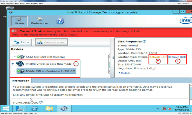
5. Observe the Fault/UID LED on the drive. If the Fault/UID LED turns steady blue and the drive is removed from the Devices list, remove the drive from the server.
For more information about the removal procedure, see "Replacing an NVMe drive."
Performing a managed hot removal in Linux
In Linux, you can perform a managed hot removal of NVMe drives from the CLI or by using Intel® Accelerated Storage Manager.
Prerequisites
· Identify that your operating system is a non-SLES Linux operating system if the VMD state is Auto. SLES operating systems do not support managed hot removal of NVMe drives in VMD Auto state.
· To perform a managed hot removal by using Intel® ASM, install Intel® ASM.
To obtain Intel® ASM, use one of the following methods:
¡ Go to https://platformsw.intel.com/KitSearch.aspx to download the software.
¡ Contact Intel Support.
Performing a managed hot removal from the CLI
1. Stop reading data from or writing data to the NVMe drive to be removed.
2. Identify the location of the NVMe drive. For more information, see "Drive configurations and numbering."
3. Access the CLI of the server.
4. Execute the lsblk | grep nvme command to identify the drive letter of the NVMe drive, as shown in Figure 47.
Figure 47 Identifying the drive letter of the NVMe drive to be removed
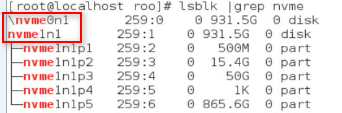
5. Execute the ledctl locate=/dev/drive_letter command to turn on the Fault/UID LED on the drive. The drive_letter argument represents the drive letter, for example, nvme0n1.
6. Execute the echo 1 > /sys/block/drive_letter/device/device/remove command to unmount the drive from the operating system. The drive_letter argument represents the drive letter, for example, nvme0n1.
7. Observe the Fault/UID LED on the drive. If the Fault/UID LED turns steady blue, remove the drive from the server.
For more information about the removal procedure, see "Replacing an NVMe drive."
Performing a managed hot removal from the Intel® ASM Web interface
1. Stop reading data from or writing data to the NVMe drive to be removed.
2. Identify the location of the NVMe drive. For more information, see "Drive configurations and numbering."
3. Run Intel® ASM.
4. Click RSTe Management.
Figure 48 Accessing RSTe Management
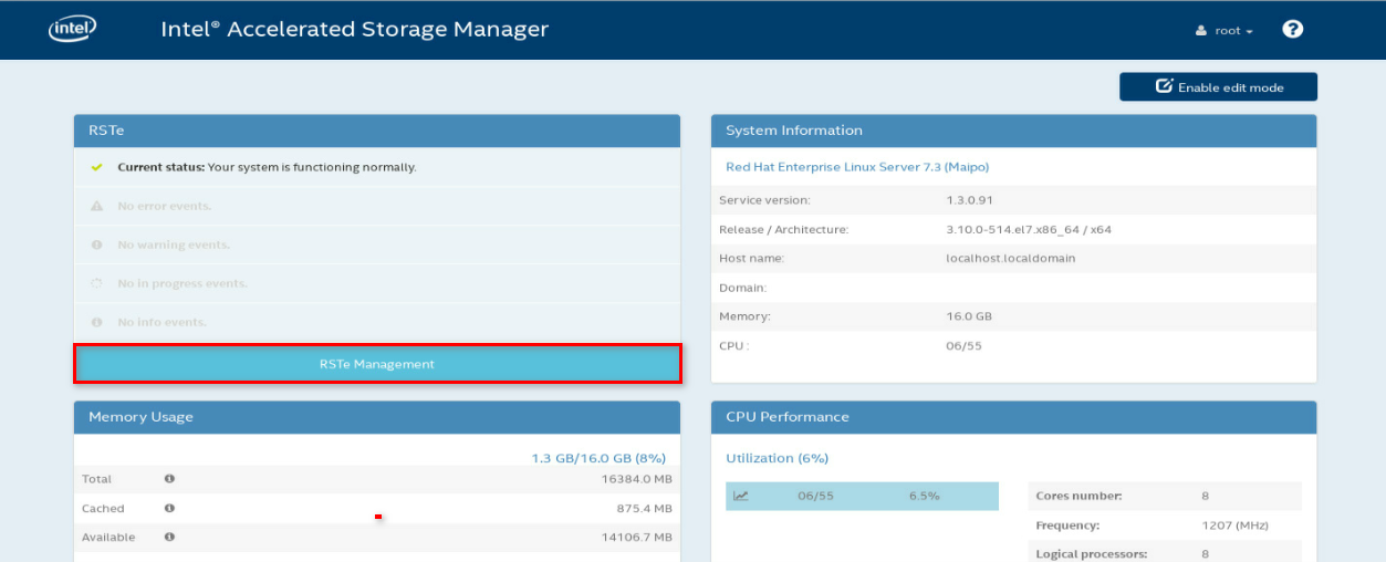
5. Expand the Intel(R) VROC(in pass-thru mode) menu to view operating NVMe drives, as shown in Figure 49.
Figure 49 Viewing operating NVMe drives

6. Click the light bulb icon to turn on the Fault/UID LED on the drive, as shown in Figure 50.
Figure 50 Turning on the drive Fault/UID LED
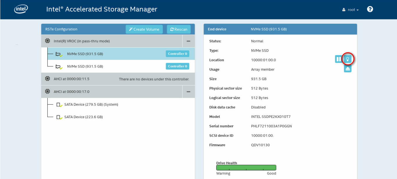
7. After the Fault/UID LED for the NVMe drive turns steady blue, click the removal icon, as shown in Figure 51.
Figure 51 Removing an NVMe drive
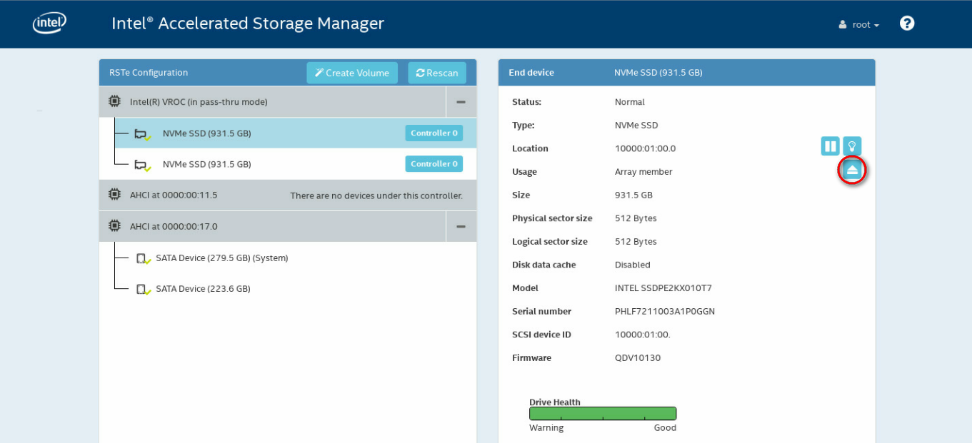
8. In the confirmation dialog box that opens, click Yes.
Figure 52 Confirming the removal
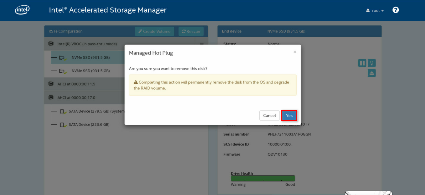
9. Remove the drive from the server. For more information about the removal procedure, see "Replacing an NVMe drive."
Appendix D Environment requirements
About environment requirements
The operating temperature requirements for the server vary depending on the server model and hardware configuration. When the general and component-based requirements conflict, use the component-based requirement.
Be aware that the actual maximum operating temperature of the server might be lower than what is stated because of poor site cooling performance. In a real data center, the server cooling performance might decrease because of adverse external factors, including poor cabinet cooling performance, high power density inside the cabinet, or insufficient spacing between devices.
General environment requirements
|
Item |
Specifications |
|
Operating temperature |
Minimum: 5°C (41°F) Maximum: Varies depending on the power consumed by the processors and presence of expansion modules. For more information, see "Operating temperature requirements." |
|
Storage temperature |
–40°C to +70°C (–40°F to +158°F) |
|
Operating humidity |
8% to 90%, noncondensing |
|
Storage humidity |
5% to 95%, noncondensing |
|
Operating altitude |
–60 m to +3000 m (–196.85 ft to +9842.52 ft) The allowed maximum temperature decreases by 0.33 °C (32.59°F) as the altitude increases by 100 m (328.08 ft) from 900 m (2952.76 ft) |
|
Storage altitude |
–60 m to +5000 m (–196.85 ft to +16404.20 ft) |
Operating temperature requirements
General guidelines
You must install six fans if you are using GPU module other than GPU-M2000 and GPU-M4000-1-X.
Performance of the following hardware components might degrade if one fan fails or is absent:
· Processors 8180, 8180M, 8168, 6154, 6146, 6144, 6254, 6244, 6240Y, 6252N, 6258R, 6246R, and 6242R.
· GPU modules (except the GPU-MLU270-S4, GPU-M2000, and GPU-M4000-1-X).
· SATA M.2 SSDs.
· DCPMMs.
8SFF server with an 8SFF drive configuration
Use Table 3 to determine the maximum operating temperature of the 8SFF server that uses an 8SFF drive configuration. A maximum server operating temperature applies if the server contains any options in its matching hardware option list.
If a single fan fails, the maximum server operating temperature drops by 5°C (41°F) and cannot exceed 35°C (95°F).
|
|
NOTE: All maximum server operating temperature values are provided on the basis that the fans are installed as needed and operating correctly. For more information about fan configurations, see the guidelines in "Installing fans." |
Table 21 Temperature requirements for the 8SFF server with an 8SFF drive configuration
|
Maximum server operating temperature |
Hardware options |
|
30°C (86°F) |
GPU modules: · GPU-P100. · GPU-V100-32G. · GPU-V100. · GPU-V100S-32G. |
|
Any of the following GPU modules used with 165W (or higher) processors: · GPU-K80-1. · GPU-M60-1-X. · GPU-P40-X. |
|
|
35°C (95°F) |
· Processor 6258R, 6246R, or 6242R. · Samsung NVMe drives. · DCPMMs. · NVMe SSD PCIe accelerator module. · Rear SATA M.2 SSD. · Power supply DPS-1600AB-13 R. · Any of the following GPU modules used with less than 165W processors: ¡ GPU-MLU270-S4. ¡ GPU-K80-1. ¡ GPU-M60-1-X. ¡ GPU-P40-X. ¡ GPU-RTX6000. |
|
40°C (104°F) |
· 15000 RPM HDDs and four operating fans. · 10000 RPM 1.2 TB (or higher) HDDs and four operating fans. · NVMe drives, excluding Samsung NVMe drives. · 64 GB LRDIMMs and a faulty fan. · Network adapter IB-MCX453A-FCAT-56/40Gb-1P or IB-MCX453A-FCAT-56/40Gb-1P-1. · Power supply DPS-1300AB-6 R. · GPU modules: ¡ GPU-P4-X. ¡ GPU-M4-1. ¡ GPU-M10-X. ¡ GPU-T4. ¡ GPU-MLU100-D3. |
|
· Supercapacitor. · Processor 8180, 8180M, 8168, 6154, 6146, 6144, 6254, 6244, 6240Y, or 6252N. · 15000 RPM HDDs and six operating fans. · 10000 RPM 1.2 TB (or higher) HDDs and six operating fans. |
|
|
50°C (122°F) |
None of the above hardware options or operating conditions exists. |
8SFF server with a 16SFF/24SFF drive configuration
Use Table 4 to determine the maximum operating temperature of the 8SFF server with a 16SFF/24SFF drive configuration. A maximum server operating temperature applies if the server contains any options in its matching hardware option list.
If a single fan fails, the maximum server operating temperature drops by 5°C (41°F) and cannot exceed 35°C (95°F).
|
|
NOTE: All maximum server operating temperature values are provided on the basis that the fans are installed as needed and operating correctly. For more information about fan configurations, see the guidelines in "Installing fans." |
Table 22 Temperature requirements for the 8SFF server with a 16SFF/24SFF drive configuration
|
Hardware options |
|
|
20°C (68°F) |
GPU-P100, GPU-V100-32G, GPU-V100, or GPU-V100S-32G in a 24SFF NVMe drive configuration that uses NVMe drives with a 3.2TB capacity (or larger). |
|
22°C (71.6°F) |
Any of the following GPU modules in a 16SFF or 24SFF drive configuration that uses 165W (or higher) processors and NVMe drives with a 3.2TB capacity (or larger): · GPU-K80-1. · GPU-M60-1-X. · GPU-P40-X. |
|
25°C (77°F) |
· GPU module GPU-P100, GPU-V100-32G, or GPU-V100, GPU-V100S-32G in any of the following drive configurations: ¡ 16SFF (8SFF SAS/SATA+8SFF NVMe, or 16SFF NVMe) with NVMe drives that have a 3.2TB capacity (or larger). ¡ 24SFF NVMe, without NVMe drives that have a 3.2TB capacity (or larger). · Any of the following GPU modules in a 16SFF or 24SFF drive configuration that uses NVMe drives with a 3.2TB capacity (or larger): ¡ GPU-K80-1. ¡ GPU-M60-1-X. ¡ GPU-P40-X. ¡ GPU-RTX6000. |
|
27°C (80.6°F) |
Any of the following GPU modules used with 165W (or higher) processors (without NVMe drives that have a 3.2TB capacity or larger): · GPU-M60-1-X. · GPU-P40-X. |
|
30°C (86°F) |
¡ GPU-MLU270-S4. ¡ GPU-K80-1. ¡ GPU-M60-1-X. ¡ GPU-P40-X. ¡ GPU-RTX6000. · GPU module GPU-P4-X, GPU-M4-1, GPU-T4, or GPU-MLU100-D3 in a 16SFF or 24SFF drive configuration that uses NVMe drives with a 3.2TB capacity (or larger). · GPU module GPU-M10-X in a 24SFF drive configuration that uses NVMe drives with a 3.2TB capacity (or larger). · GPU module GPU-P100, GPU-V100-32G, GPU-V100, or GPU-V100S-32G used with any of the following drive configurations: ¡ 16SFF SAS/SATA. ¡ 16SFF (8SFF SAS/SATA+8SFF NVMe, or 16SFF NVMe) without NVMe drives that have a 3.2TB capacity (or larger). |
|
35°C (95°F) |
· Processor 6258R, 6246R, or 6242R. · DCPMMs. · Samsung NVMe drives. · Rear drives. · NVMe SSD PCIe accelerator module. · Rear SATA M.2 SSD. · Power supply DPS-1600AB-13 R. · GPU module GPU-P4-X, GPU-M4-1, GPU-T4, or GPU-MLU100-D3 in either of the following drive configurations: ¡ 16SFF or 24 SFF (only SAS/SATA). ¡ 16SFF or 24SFF (only NVMe or SAS/SATA+NVMe) that does not use NVMe drives with a 3.2TB capacity (or larger). · GPU module GPU-M10-X used with any of the following drive configurations: ¡ 24SFF NVMe without NVMe drives that have a 3.2TB capacity (or larger). ¡ 16SFF with NVMe drives that have a 3.2TB capacity (or larger). |
|
40°C (104°F) |
· 15000 RPM HDDs and four operating fans. · 10000 RPM 1.2 TB (or higher) HDDs and four operating fans. · NVMe drives, excluding Samsung NVMe drives. · Network adapter IB-MCX453A-FCAT-56/40Gb-1P or IB-MCX453A-FCAT-56/40Gb-1P-1. · Power supply DPS-1300AB-6 R. · GPU module GPU-M10-X used with any of the following drive configurations: ¡ 16SFF SAS/SATA. ¡ 16SFF (8SFF SAS/SATA+8SFF NVMe, or 16SFF NVMe) without NVMe drives that have a 3.2TB capacity (or larger). |
|
45°C (113°F) |
None of the above hardware options or operating conditions exists. |
25SFF server with any drive configuration
Use Table 5 to determine the maximum operating temperature of the 25SFF server with any drive configuration. A maximum server operating temperature applies if the server contains any options in its matching hardware option list.
If a single fan fails, the maximum server operating temperature drops by 5°C (41°F) and cannot exceed 35°C (95°F).
|
|
NOTE: All maximum server operating temperature values are provided on the basis that the fans are installed as needed and operating correctly. For more information about fan configurations, see the guidelines in "Installing fans." |
Table 23 Temperature requirements for the 25SFF server with any drive configuration
|
Maximum server operating temperature |
Hardware options |
|
25°C (77°F) |
GPU modules: · GPU-P100. · GPU-V100-32G. · GPU-V100. · GPU-V100S-32G. |
|
Any of the following GPU modules used with 165W (or higher) processors: · GPU-K80-1. · GPU-M60-1-X. · GPU-P40-X. |
|
|
30°C (86°F) |
Any of the following GPU modules used with less than 165W processors: · GPU-MLU270-S4. · GPU-K80-1. · GPU-M60-1-X. · GPU-P40-X. · GPU-RTX6000. |
|
35°C (95°F) |
· DCPMMs. · Samsung NVMe drives. · Rear drives. · NVMe SSD PCIe accelerator module. · Rear SATA M.2 SSD. ¡ GPU-P4-X. ¡ GPU-M4-1. ¡ GPU-T4. ¡ GPU-MLU100-D3. ¡ GPU-M10-X. |
|
40°C (104°F) |
· 15000 RPM HDDs and four operating fans. · 10000 RPM 1.2 TB (or higher) HDDs and four operating fans. · NVMe drives, excluding Samsung NVMe drives. · Network adapter IB-MCX453A-FCAT-56/40Gb-1P or IB-MCX453A-FCAT-56/40Gb-1P-1. |
|
45°C (113°F) |
None of the above hardware options or operating conditions exists. |
8LFF server with any drive configuration
Use Table 6 to determine the maximum operating temperature of the 8LFF server. A maximum server operating temperature applies if the server contains any options in its matching hardware option list.
If a single fan fails, the maximum server operating temperature drops by 5°C (41°F) and cannot exceed 35°C (95°F).
|
|
NOTE: All maximum server operating temperature values are provided on the basis that the fans are installed as needed and operating correctly. For more information about fan configurations, see the guidelines in "Installing fans." |
Table 24 Temperature requirements for the 8LFF server with any drive configuration
|
Maximum server operating temperature |
Hardware options |
|
30°C (86°F) |
GPU modules: · GPU-V100-32G. · GPU-V100. · GPU-V100S-32G. |
|
Any of the following GPU modules used with 165W (or higher) processors: · GPU-K80-1. · GPU-M60-1-X. · GPU-P40-X. |
|
|
35°C (95°F) |
· Processor 6258R, 6246R, or 6242R. · DCPMMs. · NVMe SSD PCIe accelerator module. · Rear SATA M.2 SSD. · Power supply DPS-1600AB-13 R. · Any of the following GPU modules used with less than 165W processors: ¡ GPU-MLU270-S4. ¡ GPU-K80-1. ¡ GPU-M60-1-X. ¡ GPU-P40-X. ¡ GPU-RTX6000. |
|
40°C (104°F) |
· Network adapter IB-MCX453A-FCAT-56/40Gb-1P or IB-MCX453A-FCAT-56/40Gb-1P-1. · Power supply DPS-1300AB-6 R. · GPU modules: ¡ GPU-P4-X. ¡ GPU-M4-1. ¡ GPU-T4. ¡ GPU-MLU100-D3. ¡ GPU-M10-X. |
|
45°C (113°F) |
None of the above hardware options or operating conditions exists. |
12LFF server with any drive configuration
Use Table 7 to determine the maximum operating temperature of the 12LFF server. A maximum server operating temperature applies if the server contains any options in its matching hardware option list.
If a single fan fails, the maximum server operating temperature drops by 5°C (41°F) and cannot exceed 35°C (95°F).
|
|
NOTE: All maximum server operating temperature values are provided on the basis that the fans are installed as needed and operating correctly. For more information about fan configurations, see the guidelines in "Installing fans." |
Table 25 Temperature requirements for the 12LFF server with any drive configuration
|
Maximum server operating temperature |
Hardware options |
|
22°C (71.6°F) |
Any of the following GPU modules used with 165W (or higher) processors: · GPU-K80-1. · GPU-M60-1-X. · GPU-P40-X. |
|
25°C (77°F) |
· GPU modules: ¡ GPU-P100. ¡ GPU-V100-32G. ¡ GPU-V100. ¡ GPU-V100S-32G. · Any of the following GPU modules used with less than 165W processors: ¡ GPU-K80-1. ¡ GPU-M60-1-X. ¡ GPU-P40-X. |
|
30°C (86°F) |
GPU modules: · GPU-MLU270-S4. · GPU-RTX6000. |
|
35°C (95°F) |
· Processor 6258R, 6246R, or 6242R. · DCPMM. · Samsung NVMe drives. · Rear drives. · NVMe SSD PCIe accelerator module. · Rear SATA M.2 SSD. · Power supply DPS-1600AB-13 R. · GPU modules: ¡ GPU-P4-X. ¡ GPU-M4-1. ¡ GPU-T4. ¡ GPU-MLU100-D3. ¡ GPU-M10-X. |
|
40°C (104°F) |
· NVMe drives, excluding Samsung NVMe drives. · Network adapter IB-MCX453A-FCAT-56/40Gb-1P or IB-MCX453A-FCAT-56/40Gb-1P-1. · Power supply DPS-1300AB-6 R. |
|
45°C (113°F) |
None of the above hardware options or operating conditions exists. |
Appendix E Product recycling
New H3C Technologies Co., Ltd. provides product recycling services for its customers to ensure that hardware at the end of its life is recycled. Vendors with product recycling qualification are contracted to New H3C to process the recycled hardware in an environmentally responsible way.
For product recycling services, contact New H3C at
· Tel: 400-810-0504
· E-mail: [email protected]
· Website: http://www.h3c.com
Appendix F Glossary
|
Description |
|
|
B |
|
|
BIOS |
Basic input/output system is non-volatile firmware pre-installed in a ROM chip on a server's system board. The BIOS stores basic input/output, power-on self-test, and auto startup programs to provide the most basic hardware initialization, setup and control functionality. |
|
C |
|
|
CPLD |
Complex programmable logic device is an integrated circuit used to build reconfigurable digital circuits. |
|
F |
|
|
FIST |
Fast Intelligent Scalable Toolkit provided by H3C for easy and extensible server management. It can guide users to configure a server quickly with ease and provide an API interface to allow users to develop their own management tools. |
|
G |
|
|
GPU module |
Graphics processing unit module converts digital signals to analog signals for output to a display device and assists processors with image processing to improve overall system performance. |
|
H |
|
|
HDM |
Hardware Device Management is the server management control unit with which administrators can configure server settings, view component information, monitor server health status, and remotely manage the server. |
|
A module that supports hot swapping (a hot-swappable module) can be installed or removed while the server is running without affecting the system operation. |
|
|
K |
|
|
KVM |
A device that allows remote users to use their local video display, keyboard, and mouse to monitor and control remote servers. |
|
N |
|
|
Network adapter |
A network adapter, also called a network interface card (NIC), connects the server to the network. |
|
NVMe SSD expander module |
An expander module that facilitates communication between the system board and the front NVMe hard drives. The module is required if a front NVMe hard drive is installed. |
|
NVMe VROC module |
A module that works with VMD to provide RAID capability for the server to virtualize storage resources of NVMe drives. |
|
R |
|
|
RAID |
Redundant array of independent disks (RAID) is a data storage virtualization technology that combines multiple physical hard drives into a single logical unit to improve storage and security performance. |
|
Redundancy |
A mechanism that ensures high availability and business continuity by providing backup modules. In redundancy mode, a backup or standby module takes over when the primary module fails. |
|
S |
|
|
Security bezel |
A locking bezel mounted to the front of a server to prevent unauthorized access to modules such as hard drives. |
|
U |
A unit of measure defined as 44.45 mm (1.75 in) in IEC 60297-1. It is used as a measurement of the overall height of racks, as well as equipment mounted in the racks. |
|
VMD |
VMD provides hot removal, management, and fault-tolerance functions for NVMe drives to increase availability, reliability, and serviceability. |
Appendix G Acronyms
|
Acronym |
Full name |
|
B |
|
|
BIOS |
|
|
C |
|
|
CMA |
Cable Management Arm |
|
CPLD |
|
|
D |
|
|
DCPMM |
Data Center Persistent Memory Module |
|
DDR |
Double Data Rate |
|
DIMM |
Dual In-Line Memory Module |
|
DRAM |
Dynamic Random Access Memory |
|
F |
|
|
FIST |
|
|
G |
|
|
GPU |
|
|
H |
|
|
HBA |
Host Bus Adapter |
|
HDD |
Hard Disk Drive |
|
HDM |
|
|
I |
|
|
IDC |
Internet Data Center |
|
K |
|
|
KVM |
Keyboard, Video, Mouse |
|
L |
|
|
LFF |
Large Form Factor |
|
LRDIMM |
Load Reduced Dual Inline Memory Module |
|
M |
|
|
mLOM |
Modular LAN-on-Motherboard |
|
N |
|
|
NCSI |
Network Controller Sideband Interface |
|
NVMe |
Non-Volatile Memory Express |
|
P |
|
|
PCIe |
Peripheral Component Interconnect Express |
|
PDU |
Power Distribution Unit |
|
POST |
Power-On Self-Test |
|
R |
|
|
RDIMM |
Registered Dual Inline Memory Module |
|
S |
|
|
SAS |
Serial Attached Small Computer System Interface |
|
SATA |
Serial ATA |
|
SD |
Secure Digital |
|
SDS |
Secure Diagnosis System |
|
SFF |
Small Form Factor |
|
SSD |
Solid State Drive |
|
T |
|
|
TCM |
Trusted Cryptography Module |
|
TDP |
Thermal Design Power |
|
TPM |
Trusted Platform Module |
|
U |
|
|
UID |
Unit Identification |
|
UPI |
Ultra Path Interconnect |
|
UPS |
Uninterruptible Power Supply |
|
USB |
Universal Serial Bus |
|
V |
|
|
VROC |
Virtual RAID on CPU |
|
VMD |
Volume Management Device |