- Table of Contents
-
- 04-Network Connectivity
- 00-Preface
- 01-About the network connectivity configuration guide
- 02-MAC address table configuration
- 03-Ethernet link aggregation configuration
- 04-Port isolation configuration
- 05-VLAN configuration
- 06-Loop detection configuration
- 07-Spanning tree configuration
- 08-LLDP configuration
- 09-Layer 2 forwarding configuration
- 10-PPP configuration
- 11-ARP configuration
- 12-IP addressing configuration
- 13-DHCP configuration
- 14-DHCPv6 configuration
- 15-DNS configuration
- 16-NAT configuration
- 17-IP performance optimization configuration
- 18-IPv6 basics configuration
- 19-EoGRE configuration
- 20-Basic IP routing configuration
- 21-Static routing configuration
- 22-IPv6 static routing configuration
- 23-Multicast overview
- 24-IGMP snooping configuration
- 25-MLD snooping configuration
- Related Documents
-
| Title | Size | Download |
|---|---|---|
| 16-NAT configuration | 316.26 KB |
Contents
Restrictions and guidelines: NAT configuration
Configuring static NAT on an interface
Configuring outbound one-to-one static NAT
Configuring outbound net-to-net static NAT
Configuring inbound one-to-one static NAT
Configuring inbound net-to-net static NAT
Configuring dynamic NAT on an interface
Configuring outbound dynamic NAT
Configuring inbound dynamic NAT
Configuring NAT server mappings on an interface
Configuring common NAT server mappings
Configuring load sharing NAT server mappings
Configuring ACL-based NAT server mappings
Configuring NAT444 on an interface
Configuring static port block mapping for NAT444
Configuring dynamic port block mapping for NAT444
Enabling port block global sharing
Configuring DS-Lite B4 address translation on an interface
Configuring NAT session logging
Configuring NAT444 user logging
Enabling sending ICMP error messages for NAT failures
Enabling the deletion of timestamps in TCP SYN and SYN ACK packets
Display and maintenance commands for NAT
NAT overview
Network Address Translation (NAT) translates an IP address in the IP packet header to another IP address. Typically, NAT is configured on gateways to enable private hosts to access external networks and external hosts to access private network resources such as a Web server.
Basic NAT concepts
The following describes basic NAT concepts:
· NAT device—A device configured with NAT. Typically, NAT is configured on the edge device that connects the internal and external networks.
· NAT interface—An interface configured with NAT.
· NAT rule—Rules that define how to perform address translation.
· NAT address—A public IP address used for address translation, and this address is reachable from the external network. The NAT address can be manually assigned or dynamically obtained.
· NAT entry—Stores the mapping between a private IP address and a public IP address. For more information, see "NAT entries."
· Easy IP—Uses the IP address of an interface as the NAT address. The IP address of the interface can be manually assigned or be obtained through DHCP or PPPoE.
Basic NAT operating mechanism
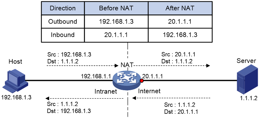
Figure 1 shows the basic NAT operating mechanism.
2. Upon receiving a response from the server, NAT translates the destination public address to the private address, and forwards the packet to the host.
The NAT operation is transparent to the terminals (the host and the server). NAT hides the private network from the external users and shows that the IP address of the internal host is 20.1.1.1.
NAT applications
Traditional NAT
Traditional NAT is configured on the interface that connects to the public network. It translates the source IP addresses of outgoing packets and destination IP addresses of incoming packets.
Twice NAT
Twice NAT translates the destination IP address on the receiving interface, and the source IP address on the sending interface. The receiving and sending interfaces are both NAT interfaces.
Twice NAT allows VPNs with overlapping addresses to access each other.
Bidirectional NAT
NAT translates the source and destination IP addresses of incoming packets on the receiving interface and outgoing packets on the sending interface.
Bidirectional NAT supports active access to external network resources from internal users when the internal and external IP addresses overlap.
NAT hairpin
NAT hairpin allows internal hosts to access each other through NAT. The source and destination IP address of the packets are translated on the interface connected to the internal network.
NAT hairpin includes P2P and C/S modes:
· P2P—Allows internal hosts to access each other through NAT. The internal hosts first register their public addresses to an external server. Then, the hosts communicate with each other by using the registered IP addresses.
· C/S—Allows internal hosts to access internal servers through NAT addresses. The destination IP address of the packet going to the internal server is translated by matching the NAT Server configuration. The source IP address is translated by matching the outbound dynamic or static NAT entries.
NAT DNS mapping
The DNS server is typically on the public network. For the users on the public network to access an internal server, you can configure the NAT Server feature on the NAT interface that connects to the public network. The NAT Server maps the public IP address and port number to the private IP address and port number of the internal server. Then the public users can access the internal server through the server's domain name or public IP address.
When a user is in the private network, the user cannot access the internal server by using the domain name of the server. This is because the DNS response contains the public IP address of the server. In this case, you can configure NAT DNS mapping to solve the problem.
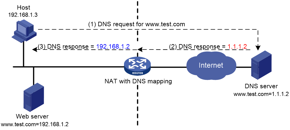
As shown in Figure 2, NAT DNS mapping works as follows:
1. The host sends a DNS request containing the domain name of the internal Web server.
2. Upon receiving the DNS response, the NAT device performs a DNS mapping lookup by using the domain name in the response. A NAT DNS mapping maps the domain name to the public IP address, public port number, and the protocol type for the internal server.
3. If a match is found, the NAT continues to compare the public address, public port number, and the protocol type with the NAT Server configuration. The NAT Server configuration maps the public IP address and port number to the private IP address and port number for the internal server.
4. If a match is found, NAT translates the public IP address in the response into the private IP address of the Web server.
5. The internal host receives the DNS response, and obtains the private IP address of the Web server.
NAT control
You can use ACLs to implement NAT control. The match criteria in the ACLs include the source IP address, source port number, destination IP address, destination port number, transport layer protocol, and VPN instance. Only packets permitted by an ACL are processed by NAT.
NAT translation methods
Static NAT
Static NAT creates a fixed mapping between a private address and a public address. It supports connections initiated from internal users to external network and from external users to the internal network. Static NAT applies to regular communications.
Dynamic NAT
Dynamic NAT uses an address pool to translate addresses. It applies to the scenario where a large number of internal users access the external network.
NO-PAT
Not Port Address Translation (NO-PAT) translates a private IP address to an IP public address. The public IP address cannot be used by another internal host until it is released.
NO-PAT supports all IP packets.
PAT
Port Address Translation (PAT) translates multiple private IP addresses to a single public IP address by mapping the private IP address and source port to the public IP address and a unique port. PAT supports TCP and UDP packets, and ICMP request packets.
Figure 3 PAT operation
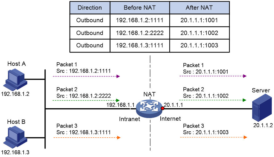
As shown in Figure 3, PAT translates the source IP addresses of the three packets to the same IP public address and translates their port numbers to different port numbers. Upon receiving a response, PAT translates the destination address and port number of the response, and forwards it to the target host.
PAT supports the following mappings:
· Endpoint-Independent Mapping (EIM)—Uses the same IP and port mapping (EIM entry) for packets from the same source IP and port to any destinations. EIM allows external hosts to initiate connections to the translated IP addresses and ports of internal hosts. It allows internal hosts behind different NAT gateways to access each other.
· Address and Port-Dependent Mapping (APDM)—Uses different IP and port mappings for packets from the same source IP and port to different destination IP addresses and ports. APDM allows an external host to initiate connections to an internal host only under the condition that the internal host has previously accessed the external host. It is secure, but it does not allow internal hosts behind different NAT gateways to access each other.
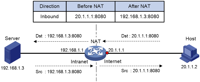
NAT Server
The NAT Server feature maps a public address and port number to the private IP address and port number of an internal server. This feature allows servers in the private network to provide services for external users.
Figure 4 shows how NAT Server works:
1. Upon receiving a request from the host, NAT translates the public destination IP address and port number to the private IP address and port number of the internal server.
2. Upon receiving a response from the server, NAT translates the private source IP address and port number to the public IP address and port number.
Port block-based NAT
Port block-based NAT is a PAT translation based on port ranges. It maps multiple private IP addresses to one public IP address and uses a different port block for each private IP address. For example, the private IP address 10.1.1.1 of an internal host is mapped to the public IP address 202.1.1.1 and port block 10001 to 10256. When the internal host accesses public hosts, the source IP address 10.1.1.1 is translated to 202.1.1.1, and the source ports are translated to ports in the port block 10001 to 10256.
Port block-based NAT includes static and dynamic mappings.
Static port block mapping
The NAT gateway computes a static port block mapping before address translation. The mapping is between a private IP address and a public IP address with a port block.
When an internal user initiates a connection to the external network, the system performs the following operations:
· Locates a static mapping based on the private IP address of the user and obtains the public IP address and the port block in the mapping.
· Selects a public port number in the port block.
· Translates the private IP address to the public IP address and assigns the selected public port number.
The NAT gateway uses private IP addresses, public IP addresses, a port range, and a port block size to compute static mappings:
1. Divides the port range by the port block size to get the number of available port blocks for each public IP address.
This value is the base number for mapping.
2. Sorts the port blocks in ascending order of the start port number in each block.
3. Sorts the private IP addresses and the public IP addresses separately in ascending order.
4. Maps the first base number of private IP addresses to the first public IP address and its port blocks in ascending order.
For example, the number of available port blocks of each public IP address is m. The first m private IP addresses are mapped to the first public IP address and the m port blocks in ascending order. The next m private IP addresses are mapped to the second IP address and the m port blocks in ascending order. The other static port block mappings are created by analogy.
Dynamic port block mapping
When an internal user initiates a connection to the external network, the dynamic port block-based NAT operates as follows:
1. Uses ACLs to implement translation control. It processes only packets that match an ACL permit rule.
2. Creates a mapping from the internal user's private IP address to a public IP address and a port block.
3. Translates the private IP address to the public IP address, and the source ports to ports in the selected port block for subsequent connections from the private IP address.
4. Withdraws the port block and deletes the dynamic port block mapping when all connections from the private IP address are disconnected.
Dynamic port block mapping supports port block extending. If the ports in the port block for a private address are all occupied, dynamic port block mapping translates the source port to a port in an extended port block.
NAT entries
NAT session entry
NAT creates a NAT session entry for a session and creates an address mapping for the first packet in the session.
A NAT session entry contains extended NAT information, such as interface and translation method. Subsequent packets of the session are translated by using this entry.
· If the direction of the subsequent packets is the same as the direction of the first translated packets, NAT performs the source and destination address translation the same as the first packet.
· If the direction of the subsequent packets is the opposite direction, NAT perform reverse address translation. For example, if the source address of the first packets is translated, then the destination address of the subsequent packets is translated.
The session management module maintains the updating and aging of NAT session entries. For information about session management, see Security Configuration Guide.
EIM entry
If EIM is configured on the NAT device, the PAT mode will first create a NAT session entry, and then an EIM entry. The EIM entry is a 3-tuple entry, and it maps a private address/port to a public address/port. The EIM entry ensures:
· Subsequent new connections originating from the same source IP and port uses the same translation as the initial connection.
· Translates the address for new connections initiated from external hosts to the NAT address and port number based on the EIM entry.
An EIM entry ages out after all related NAT session entries age out.
NO-PAT entry
A NO-PAT entry maps a private address to a public address. The same mapping applies to subsequent connections originating from the same source IP.
A NO-PAT entry can also be created during the ALG process for NAT. For information about NAT ALG, see "NAT ALG."
A NO-PAT entry ages out after all related NAT session entries age out.
Port block-based entry
A port block-based entry maps a private IP address to a public IP address and a port block.
Port block-based entries include static and dynamic port block mappings. For information about these mappings, see "Static port block mapping" and "Dynamic port block mapping."
NAT ALG
NAT ALG (Application Level Gateway) translates address or port information in the application layer payloads to ensure connection establishment.
For example, an FTP application includes a data connection and a control connection. The IP address and port number for the data connection depend on the payload information of the control connection. This requires NAT ALG to translate the address and port information for data connection establishment.
Configuring NAT
Restrictions and guidelines: NAT configuration
The general restrictions and guidelines are as follows:
· Configure an ACL to identify the IP addresses to be translated. The match criteria include the source IP address, source port number, destination IP address, destination port number, and transport layer protocol.
· If you perform all the translation methods on an interface, the NAT rules are sorted in the following descending order:
a. NAT Server.
b. Static NAT.
c. NAT444 static port blocking mapping.
d. Dynamic NAT, NAT444 dynamic port block mapping, and DS-Lite B4 address translation.
Dynamic NAT, NAT444 dynamic port block mapping, and DS-Lite B4 address translation have the same priority. Dynamic NAT rules and NAT444 dynamic port block mapping rules are sorted in descending order of ACL numbers and are effective for IPv4 packets. DS-Lite B4 address translation rules are effective for IPv6 packets.
NAT sorts rules of the same type in descending order of NAT priority values. A NAT rule with a smaller priority value represents a higher priority for packet translation. You can move the NAT rules of the same type to change their priority for packet matching.
After you move a rule to the line before or after a reference NAT rule, the priority of the moved rule is changed, but the priority of the reference NAT rule is not.
· If the rule is moved to the line before the reference NAT rule, the priority of the moved rule equals the priority value of the reference rule minus one.
· If the rule is moved to the line after the reference NAT rule, the priority of the moved rule equals the priority value of the reference rule plus one.
NAT tasks at a glance
To configure NAT, perform the following tasks:
1. Configuring an address translation method
¡ Configuring static NAT on an interface
¡ Configuring dynamic NAT on an interface
¡ Configuring NAT server mappings on an interface
¡ Configuring NAT444 on an interface
¡ Configuring DS-Lite B4 address translation on an interface
2. (Optional.) Configuring NAT hairpin
3. (Optional.) Configuring NAT ALG
4. (Optional.) Configuring NAT logging
5. (Optional.) Enabling sending ICMP error messages for NAT failures
Configuring static NAT on an interface
Restrictions and guidelines
Typically, configure inbound static NAT with outbound dynamic NAT or outbound static NAT to implement bidirectional NAT.
Prerequisites
Before configuring static NAT, you must perform the following tasks:
· Configure an ACL to identify the IP addresses to be translated. For more information about ACLs, see Security Configuration Guide.
· Manually add a route for inbound static NAT. Use local-ip or local-network as the destination address, and use global-ip, an address in global-network, or the next hop directly connected to the output interface as the next hop.
Configuring outbound one-to-one static NAT
About this task
For address translation from a private IP address to a public IP address, configure outbound one-to-one static NAT on the interface connected to the external network.
· When the source IP address of an outgoing packet matches the local-ip, the source IP address is translated into the global-ip.
· When the destination IP address of an incoming packet matches the global-ip, the destination IP address is translated into the local-ip.
Procedure
1. Enter system view.
system-view
2. Configure a one-to-one mapping for outbound static NAT.
nat static outbound local-ip global-ip [ acl { ipv4-acl-number | name ipv4-acl-name } [ reversible ] ] [ rule rule-name ] [ priority priority ] [ disable ] [ counting ]
3. (Optional.) Rearrange outbound one-to-one mapping NAT rules to adjust their priorities.
nat static outbound rule move nat-rule-name1 { after | before } nat-rule-name2
4. Enter interface view.
interface interface-type interface-number
5. Enable static NAT on the interface.
nat static enable
By default, static NAT is disabled.
Configuring outbound net-to-net static NAT
About this task
For address translation from a private network to a public network, configure outbound net-to-net static NAT on the interface connected to the external network.
· When the source IP address of an outgoing packet matches the private address range, the source IP address is translated into a public address in the public address range.
· When the destination IP address of an incoming packet matches the public address range, the destination IP address is translated into a private address in the private address range.
Procedure
1. Enter system view.
system-view
2. Configure a net-to-net mapping for outbound static NAT.
nat static outbound net-to-net local-start-address local-end-address global global-network { mask-length | mask } [ acl { ipv4-acl-number | name ipv4-acl-name } [ reversible ] ] [ rule rule-name ] [ priority priority ] [ disable ] [ counting ]
3. Enter interface view.
interface interface-type interface-number
4. Enable static NAT on the interface.
nat static enable
By default, static NAT is disabled.
Configuring inbound one-to-one static NAT
About this task
For address translation from a public IP address to a private IP address, configure inbound one-to-one static NAT.
· When the source IP address of an incoming packet matches the global-ip, the source IP address is translated into the local-ip.
· When the destination IP address of an outgoing packet matches the local-ip, the destination IP address is translated into the global-ip.
Procedure
1. Enter system view.
system-view
2. Configure a one-to-one mapping for inbound static NAT.
nat static inbound global-ip local-ip [ acl { ipv4-acl-number | name ipv4-acl-name } [ reversible ] ] [ rule rule-name ] [ priority priority ] [ disable ] [ counting ]
3. Enter interface view.
interface interface-type interface-number
4. Enable static NAT on the interface.
nat static enable
By default, static NAT is disabled.
Configuring inbound net-to-net static NAT
About this task
For address translation from a public network to a private network, configure inbound net-to-net static NAT.
· When the source IP address of an incoming packet matches the public address range, the source IP address is translated into a private address in the private address range.
· When the destination IP address of an outgoing packet matches the private address range, the destination IP address is translated into a public address in the public address range.
Procedure
1. Enter system view.
system-view
2. Configure a net-to-net mapping for inbound static NAT.
nat static inbound net-to-net global-start-address global-end-address local local-network { mask-length | mask } [ acl { ipv4-acl-number | name ipv4-acl-name } [ reversible ] ] [ rule rule-name ] [ priority priority ] [ disable ] [ counting ]
3. Enter interface view.
interface interface-type interface-number
4. Enable static NAT on the interface.
nat static enable
By default, static NAT is disabled.
Configuring dynamic NAT on an interface
Restrictions and guidelines
You can configure multiple inbound or outbound dynamic NAT rules.
· A NAT rule with an ACL takes precedence over a rule without any ACL.
· If two ACL-based dynamic NAT rules are configured, the rule with the higher ACL number has higher priority.
Prerequisites
Before configuring dynamic NAT, you must perform the following tasks:
· Configure an ACL to identify the IP addresses to be translated. For more information about ACLs, see Security Configuration Guide.
· Determine whether to enable the Easy IP feature. If you use the IP address of an interface as the NAT address, you are configuring Easy IP.
· Determine a public IP address pool for address translation.
· Determine whether to translate port numbers. Use NO-PAT to translate only IP addresses and PAT to translate both IP addresses and port numbers.
Configuring outbound dynamic NAT
About this task
To translate private IP addresses into public IP addresses, configure outbound dynamic NAT on the interface connected to the external network.
Procedure
1. Enter system view.
system-view
2. Create a NAT address group and enter its view.
nat address-group group-id
3. Add an address range to the address group.
address start-address end-address [ name group-name ]
You can add multiple address ranges to an address group.
The address ranges must not overlap.
4. Return to system view.
quit
5. Enter interface view.
interface interface-type interface-number
6. Configure outbound dynamic NAT. Choose the options to configure as needed:
¡ Configure NO-PAT.
nat outbound [ ipv4-acl-number | name ipv4-acl-name ] address-group { group-id | name group-name } no-pat [ reversible ] [ rule rule-name ] [ priority priority ] [ disable ] [ description text ] [ counting ]
¡ Configure PAT.
nat outbound [ ipv4-acl-number | name ipv4-acl-name ][ address-group { group-id | name group-name } ] [ port-preserved ] [ rule rule-name ] [ priority priority ] [ disable ] [ description text ] [ counting ]
You can configure multiple outbound dynamic NAT rules on an interface.
|
Parameter |
Description |
|
address-group |
If you do not specify this keyword, the IP address of the interface is used as the NAT address. Easy IP is implemented. |
|
no-pat reversible |
If you specify these keywords, you enable reverse address translation. Reverse address translation uses existing NO-PAT entries to translate the destination address for connections actively initiated from the external network to the internal network. The destination address is translated into the private IP address in the matching NO-PAT entry. |
7. (Optional.) Configure a PAT mapping mode.
a. Return to system view.
quit
b. Configure a PAT mapping mode.
nat mapping-behavior endpoint-independent [ acl { ipv4-acl-number | name ipv4-acl-name } ]
The default mapping mode is Address and Port-Dependent Mapping.
This command takes effect only on outbound dynamic NAT for PAT.
8. (Optional.) Rearrange outbound dynamic NAT rules to adjust their priorities.
nat outbound rule move nat-rule-name1 { after | before } nat-rule-name2
Configuring inbound dynamic NAT
Restrictions and guidelines
Do not configure inbound dynamic NAT alone. Typically, inbound dynamic NAT functions with outbound dynamic NAT, or outbound static NAT to implement bidirectional NAT.
As a best practice, manually create a route because it takes time to automatically add routes.
Procedure
1. Enter system view.
system-view
2. Create a NAT address group and enter its view.
nat address-group group-id
3. Add an address range to the address group.
address start-address end-address [ name group-name ]
You can add multiple address ranges to an address group.
The address ranges in address groups must not overlap.
4. Return to system view.
quit
5. Enter interface view.
interface interface-type interface-number
6. Configure inbound dynamic NAT.
nat inbound { ipv4-acl-number | name ipv4-acl-name } address-group { group-id | name group-name } [ no-pat [ reversible ] [ add-route ] ] [ rule rule-name ] [ priority priority ] [ disable ] [ description text ] [ counting ]
You can configure multiple inbound dynamic NAT rules on an interface.
|
Parameter |
Description |
|
no-pat reversible |
If you specify these keywords, you enable reverse address translation. Reverse address translation uses existing NO-PAT entries to translate the destination address for connections actively initiated from the external network to the internal network. The destination address is translated into the private IP address in the matching NO-PAT entry. |
|
add-route |
This keyword enables the device to automatically add a route destined for the private address when an inbound dynamic NAT rule is matched. The output interface is the NAT interface, and the next hop is the source address before translation. If you do not specify this keyword, you must manually add the route. |
7. (Optional.) Rearrange inbound dynamic NAT rules to adjust their priorities.
nat inbound rule move nat-rule-name1 { after | before } nat-rule-name2
Configuring NAT server mappings on an interface
About NAT server mappings
Typically, the NAT Server feature is configured on the interface connected to the external network to allow servers to provide services for external users. A NAT server mapping (also called NAT server rule) maps a public IP address and port number to the private IP address and port number of the internal server.
The NAT Server feature can be implemented by configuring the following server mappings:
· Common NAT server mapping—Maps the private IP address and the port number of the internal server to a public IP address and a port number. This method allows external hosts to access the internal server by using the specified public IP address.
· Load sharing NAT server mapping—You can add multiple internal servers to an internal server group so that these servers provide the same service for external hosts. The NAT device chooses one internal server based on the weight and number of connections of the servers to respond to a request from an external host to the public address of the internal server group.
· ACL-based NAT server mapping—An extension of common NAT server mapping. A common NAT server mapping maps the private IP address of the internal server to a single public IP address. An ACL-based NAT server mapping maps the private IP address of the internal server to a set of public IP addresses defined by an ACL. If the destination address of a packet matches a permit rule in the ACL, the destination address is translated into the private IP address of the internal server.
Restrictions and guidelines
When you configure a load shared NAT server mapping, you must make sure a user uses the same public address and public port to access the same service on an internal server. For this purpose, make sure value N in the following mappings is equal to or less than the number of servers in the internal server group:
· One public address and N consecutive public port numbers are mapped to one internal server group.
· N consecutive public addresses and one public port number are mapped to one internal server group.
When you roll back configuration in a version that supports the automatic NAT rule name assignment, a rollback failure message is displayed if the no automatically assigned names exist in the replacement configuration file.
For example, the system compares the configuration in the replacement configuration file and the configuration after the rollback and displays a rollback failure message in the following conditions:
· The replacement configuration file has the following configuration: nat server global 112.1.1.1 inside 192.168.20.1.
· The NAT rule configuration after the rollback is nat server global 112.1.1.1 inside 192.168.20.1 rule NAT server rule_10 (NAT server rule_10 indicating an NAT rule name automatically assigned by the system).
In this case, the NAT rule configuration in the replacement configuration file has been issued and you can ignore this failure message.
Configuring common NAT server mappings
1. Enter system view.
system-view
2. Enter interface view.
interface interface-type interface-number
3. Configure common NAT server mappings. Choose the options to configure as needed:
¡ A single public address with a single or no public port:
nat server [ protocol pro-type ] global { global-address | current-interface | interface interface-type interface-number } [ global-port ] inside local-address [ local-port ] [ acl { ipv4-acl-number | name ipv4-acl-name } ] [ reversible ] [ rule rule-name ] [ disable ] [ counting ]
¡ A single public address with consecutive public ports:
nat server protocol pro-type global { global-address | current-interface | interface interface-type interface-number } global-port1 global-port2 inside { { local-address | local-address1 local-address2 } local-port | local-address local-port1 local-port2 } [ acl { ipv4-acl-number | name ipv4-acl-name } ] [ rule rule-name ] [ disable ] [ counting ]
¡ Consecutive public addresses with a single or no public port:
nat server protocol pro-type global global-address1 global-address2 [ global-port ] inside { local-address | local-address1 local-address2 } [ local-port ] [ acl { ipv4-acl-number | name ipv4-acl-name } ] [ rule rule-name ] [ disable ] [ counting ]
¡ Consecutive public addresses with a single public port:
nat server protocol pro-type global global-address1 global-address2 global-port inside local-address local-port1 local-port2 [ acl { ipv4-acl-number | name ipv4-acl-name } ] [ rule rule-name ] [ disable ] [ counting ]
You can configure multiple NAT server mappings on an interface.
Configuring load sharing NAT server mappings
1. Enter system view.
system-view
2. Create a NAT server group and enter its view.
nat server-group group-id
By default, no NAT server groups exist.
3. Add an internal server into the group.
inside ip inside-ip port port-number [ weight weight-value ]
You can add multiple internal servers to a group.
4. Return to system view.
quit
5. Enter interface view.
interface interface-type interface-number
6. Configure a load sharing NAT server mapping.
nat server protocol pro-type global { { global-address | nat server protocol pro-type global { { global-address | current-interface | interface interface-type interface-number } { global-port | global-port1 global-port2 } | global-address1 global-address2 global-port } inside server-group group-id [ acl { ipv4-acl-number | name ipv4-acl-name } ] [ rule rule-name ] [ disable ] [ counting ]
You can configure multiple load sharing NAT server mappings on an interface.
Configuring ACL-based NAT server mappings
1. Enter system view.
system-view
2. Enter interface view.
interface interface-type interface-number
3. Configure an ACL-based NAT server mapping.
nat server global { ipv4-acl-number | name ipv4-acl-name } inside local-address [ local-port ] [ rule rule-name ] [ priority priority ] [ disable ] [ description text ] [ counting ]
You can configure multiple NAT server mappings on an interface.
4. (Optional.) Rearrange ACL-based NAT server mappings to adjust their priorities.
nat server rule move nat-rule-name1 { after | before } nat-rule-name2
Configuring NAT444 on an interface
About NAT444
NAT444 provides outbound address translation, and it is configured on the interface connected to the public network. By configuring NAT444 address translation on the NAT444 gateway, multiple private IP addresses are mapped to one public IP address and a different port block is used for each private IP address
Restrictions and guidelines
To configure dynamic port block mapping for NAT444, you must configure port block parameters in the NAT address group.
Configuring static port block mapping for NAT444
1. Enter system view.
system-view
2. Create a NAT port block group, and enter its view.
nat port-block-group group-id
3. Add a private IP address range to the port block group.
local-ip-address start-address end-address
You can add multiple private IP address ranges to one port block group, but they cannot overlap.
4. Add a public IP address range to the port block group.
global-ip-pool start-address end-address
You can add multiple public IP address ranges to one port block group, but they cannot overlap.
5. Configure the port range for the public IP addresses.
port-range start-port-number end-port-number
By default, the port range is 1 to 65535.
6. Set the port block size.
block-size block-size
By default, the port block size is 256.
7. Return to system view.
quit
8. Enter interface view.
interface interface-type interface-number
9. Configure a static outbound port block mapping rule on the interface.
nat outbound port-block-group group-id [ rule rule-name ] [ counting ]
By default, no port block mapping rule is configured on an interface.
You can configure multiple port block mapping rules on one interface.
10. (Optional.) Configure a PAT mapping mode.
a. Return to system view.
quit
b. Configure a PAT mapping mode.
nat mapping-behavior endpoint-independent [ acl { ipv4-acl-number | name ipv4-acl-name } ]
The default mapping mode is Address and Port-Dependent Mapping.
Configuring dynamic port block mapping for NAT444
Restrictions and guidelines
You can use one of the following methods to add IP addresses to a NAT address group:
· Method 1—Adding one or multiple address ranges.
· Method 2—Adding the IP address of the specified interface. This method supports the cooperation between dynamic NAT port block mappings and Easy IP and supports user tracing.
Only one method is supported for a NAT address group.
Use Method 2 if the IP address after translation is the IP address of the interface connected to the external network and the IP address is dynamically obtained through DHCP or PPPoE. This method avoids the inaccurate NAT IP address information caused by the IP address change of the interface.
Procedure
1. Enter system view.
system-view
2. (Optional.) Configure a PAT mapping mode.
nat mapping-behavior endpoint-independent [ acl { ipv4-acl-number | name ipv4-acl-name } ]
The default mapping mode is Address and Port-Dependent Mapping.
3. Create a NAT address group, and enter its view.
nat address-group group-id [ name group-name ]
4. Add addresses to the NAT address group. Choose one option as needed:
¡ Add IP address ranges to the NAT address group.
address start-address end-address
You can add multiple public IP address ranges to an address group.
The IP address ranges in address groups cannot overlap.
Execute the following command to exclude IP addresses from being used in address translation.
exclude-ip start-address end-address
The end-address must not be lower than the start-address. If they are the same, you specify only one IP address.
¡ Add the IP address of an interface to the NAT address group.
address interface interface-type interface-number
By default, no interface address exists in the NAT address group.
You can specify only one interface for a NAT address group.
5. (Optional.) Configure the port range for the public IP addresses.
port-range start-port-number end-port-number
By default, the port range is 1 to 65535.
The configuration takes effect only on PAT translation mode.
6. Configure port block parameters.
port-block block-size block-size [ extended-block-number extended-block-number ]
The configuration takes effect only on PAT translation mode.
7. Return to system view.
quit
8. Enter interface view.
interface interface-type interface-number
9. Configure PAT for outbound dynamic NAT.
nat outbound [ ipv4-acl-number | name ipv4-acl-name ] [ address-group { group-id | name group-name } [ port-preserved ] [ rule rule-name ] [ priority priority ] [ disable ] [ description text ] [ counting ]
By default, no outbound dynamic NAT rules exist.
The port-preserved keyword does not take effect on dynamic NAT444.
10. (Optional.) Enable dynamic port block mapping synchronization.
a. Return to system view.
quit
b. Enable dynamic port block mapping synchronization.
nat port-block synchronization enable
By default, dynamic port block mapping synchronization is disabled.
Enabling port block global sharing
About this task
When multiple interfaces have dynamic NAT port block mapping configured, the interfaces might create different port block mappings for packets from the same IP address. You can use this command to configure the interfaces to use the same port block mapping for translating packets from the same IP address.
Procedure
1. Enter system view
system-view
2. Enable port block global sharing.
nat port-block global-share enable
By default, port block global sharing is disabled.
Configuring DS-Lite B4 address translation on an interface
About this task
DS-Lite B4 address translation is configured on the AFTR's interface connected to the external network. It uses an IPv6 ACL to identify packets to be NATed.
DS-Lite B4 address translation supports only the dynamic port block mapping method.
Procedure
1. Enter system view.
system-view
2. (Optional.) Configure a PAT mapping mode.
nat mapping-behavior endpoint-independent [ acl { ipv4-acl-number | name ipv4-acl-name } ]
The default mapping mode is Address and Port-Dependent Mapping.
3. Create a NAT address group, and enter its view.
nat address-group group-id [ name group-name ]
4. Add a public IP address range to the NAT address group.
address start-address end-address
You can add multiple public IP address ranges to an address group.
The IP address ranges in address groups cannot overlap.
5. (Optional.) Exclude IP addresses from being used in address translation.
exclude-ip start-address end-address
The end-address must not be lower than the start-address. If they are the same, you specify only one IP address.
6. Configure the port range for the public IP addresses.
port-range start-port-number end-port-number
By default, the port range is 1 to 65535.
The configuration takes effect only on PAT translation mode.
7. Configure port block parameters.
port-block block-size block-size [ extended-block-number extended-block-number ]
By default, no port block parameters exist.
The configuration takes effect only on PAT translation mode.
8. Return to system view.
quit
9. Enter interface view.
interface interface-type interface-number
10. Configure DS-Lite B4 address translation.
nat outbound ds-lite-b4 { ipv6-acl-number | name ipv6-acl-name } address-group group-id
By default, DS-Lite B4 address translation is not configured.
11. (Optional.) Enable dynamic port block mapping synchronization.
a. Return to system view.
quit
b. Enable dynamic port block mapping synchronization.
nat port-block synchronization enable
By default, dynamic port block mapping synchronization is disabled.
Configuring NAT hairpin
About this task
NAT hairpin allows internal hosts to access each other or allows internal hosts to access internal servers. The source and destination IP addresses of the packets are translated on the interface connected to the internal network.
Restrictions and guidelines
NAT hairpin works in conjunction with NAT Server, outbound dynamic NAT, or outbound static NAT. To provide service correctly, you must configure NAT hairpin on the same interface module as its collaborative NAT feature.
To configure the P2P mode, you must configure outbound PAT on the interface connected to the external network and enable the EIM mapping mode.
Procedure
1. Enter system view.
system-view
2. Enter interface view.
interface interface-type interface-number
3. Enable NAT hairpin.
nat hairpin enable
By default, NAT hairpin is disabled.
Configuring NAT ALG
About this task
NAT ALG translates address or port information in the application layer payload to ensure connection establishment.
For example, an FTP application includes a data connection and a control connection. The IP address and port number for the data connection depend on the payload information of the control connection. This requires NAT ALG to translate the address and port information to establish the data connection.
Procedure
1. Enter system view
system-view
2. Configure NAT ALG for a protocol or all protocols.
nat alg { all | dns | ftp | icmp-error | ils | mgcp | nbt | pptp | rsh | rtsp | sccp | sqlnet | tftp | xdmcp }
By default, NAT ALG is enabled for DNS, FTP, ICMP error messages, RTSP, and PPTP, and is disabled for the other supported protocols.
Configuring NAT logging
Configuring NAT session logging
About this task
NAT session logging records NAT session information, including translation information and access information.
A NAT device generates NAT session logs for the following events:
· NAT session establishment.
· NAT session removal. This event occurs when you add a configuration with a higher priority, remove a configuration, change ACLs, when a NAT session ages out, or when you manually delete a NAT session.
· Active NAT session logging.
Procedure
1. Enter system view.
system-view
2. Enable NAT logging.
nat log enable [ acl { ipv4-acl-number | name ipv4-acl-name } ]
By default, NAT logging is disabled.
3. Enable NAT session logging.
¡ For NAT session establishment events:
nat log flow-begin
¡ For NAT session removal events:
nat log flow-end
¡ For active NAT flows:
nat log flow-active minutes
By default, NAT session logging is disabled.
Configuring NAT444 user logging
About this task
NAT444 user logs are used for user tracing. The NAT444 gateway generates a user log whenever it assigns or withdraws a port block. The log includes the private IP address, public IP address, and port block. You can use the public IP address and port numbers to locate the user's private IP address from the user logs.
A NAT444 gateway generates NAT user logs when one of the following events occurs:
· A port block is assigned.
For the NAT444 static port block mapping, the NAT444 gateway generates a user log when it translates the first connection from a private IP address.
For the NAT444 dynamic port block mapping, the NAT444 gateway generates a user log when it assigns or extends a port block for a private IP address.
· A port block is withdrawn.
For the NAT444 static port block mapping, the NAT444 gateway generates a user log when all connections from a private IP address are disconnected.
For the NAT444 dynamic port block mapping, the NAT444 gateway generates a user log when all the following conditions are met:
¡ All connections from a private IP address are disconnected.
¡ The port blocks (including the extended ones) assigned to the private IP address are withdrawn.
¡ The corresponding mapping entry is deleted.
Prerequisites
Before configuring NAT444 user logging, you must configure the custom NAT444 log generation and outputting features. For more information, see the information center in Network Management and Monitoring Configuration Guide.
Procedure
1. Enter system view.
system-view
2. Enable NAT logging.
nat log enable [ acl { ipv4-acl-number | name ipv4-acl-name } ]
By default, NAT logging is disabled.
The acl keyword does not take effect on NAT444 user logging.
3. Enable NAT444 user logging. Choose the options to configure as needed:
¡ For port block assignment:
nat log port-block-assign
¡ For port block withdrawal:
nat log port-block-withdraw
By default, NAT444 user logging is disabled.
Configuring NAT alarm logging
About this task
Packets that need to be translated are dropped if the NAT resources are not enough. In NO-PAT, the NAT resources refer to the public IP addresses. In EIM PAT, the NAT resources refer to public IP addresses and ports. NAT alarm logging monitors the usage of NAT resources and outputs logs if the NAT resources are not enough.
Restrictions and guidelines
The nat log alarm command take effect only after you use the nat log enable command to enable NAT logging.
Prerequisites
Before configuring NAT alarm logging, you must configure the custom NAT log generation and outputting features. For more information, see the information center in System Management Configuration Guide.
Procedure
1. Enter system view.
system-view
2. Enable NAT logging.
nat log enable [ acl { ipv4-acl-number | name ipv4-acl-name } ]
By default, NAT logging is disabled.
The acl keyword does not take effect on NAT alarm logging.
3. Enable NAT alarm logging.
nat log alarm
By default, NAT alarm logging is disabled.
An NAT alarm log is output when NAT resources run out.
Enabling sending ICMP error messages for NAT failures
About this task
By default, the device does not send ICMP error messages when NAT fails. Disabling sending ICMP error messages for NAT failures reduces useless packets, saves bandwidth, and avoids exposing the firewall IP address to the public network.
Restrictions and guidelines
Enable this feature for traceroute because the traceroute function requires ICMP error packets.
Procedure
1. Enter system view.
system-view
2. Enable sending ICMP error messages for NAT failures.
nat icmp-error reply
By default, no ICMP error messages are sent for NAT failures.
Enabling the deletion of timestamps in TCP SYN and SYN ACK packets
About this task
With this feature configured, the system deletes the timestamps from the TCP SYN and SYN ACK packets after dynamic address translation.
If PAT mode is configured on an interface by using nat inbound or nat outbound, and the tcp_timestams and tcp_tw_recycle function is configured on the TCP server, TCP connections might not be established. To solve the problem, you can shut down the tcp_tw_recycle function or configure the nat timestamp delete command.
Procedure
1. Enter system view.
system-view
2. Enable the deletion of timestamps in TCP SYN and SYN ACK packets
nat timestamp delete
By default, the deletion of timestamps in TCP SYN and SYN ACK packets is disabled.
Display and maintenance commands for NAT
Execute display commands in any view and reset commands in user view.
|
Task |
Command |
|
Display the NAT ALG status for all supported protocols |
display nat alg |
|
Display all NAT configuration information. |
display nat all |
|
Display NAT address group information. |
display nat address-group [ group-id ] |
|
Display information about NAT EIM entries. |
display nat eim |
|
Display inbound dynamic NAT configuration. |
display nat inbound |
|
Display NAT logging configuration. |
display nat log |
|
Display information about NAT NO-PAT entries. |
display nat no-pat |
|
Display outbound dynamic NAT configuration. |
display nat outbound |
|
Display NAT server mappings. |
display nat server |
|
Display internal server group configuration. |
display nat server-group [ group-id ] |
|
Display NAT sessions. |
display nat session [ [ responder ] { source-ip source-ip | destination-ip destination-ip } * ] [ verbose ] |
|
Display static NAT mappings. |
display nat static |
|
Display NAT statistics. |
display nat statistics [ summary ] |
|
Display static outbound port block mapping rules for NAT444 |
display nat outbound port-block-group |
|
Display NAT port block group configuration. |
display nat port-block-group [ group-id ] |
|
Display NAT port block mappings. |
display nat port-block { dynamic [ address-group { group-id | name group-name } ] [ ds-lite-b4 ] | static [ port-block-group group-id ] } |
|
display nat port-block-usage [ address-group group-id ] |
|
|
clear NAT counting statistics |
reset nat count statistics { all | dynamic | static } |
|
Clear NAT sessions. |
reset nat session |
NAT configuration examples
Example: Configuring outbound one-to-one static NAT
Network configuration
As shown in Figure 5, configure static NAT to allow the client at 192.168.1.10/24 to access the Internet.

Procedure
# Assign IP addresses to interfaces. (Details not shown.)
# Configure a one-to-one static NAT mapping between private address 192.168.1.10 and public address 202.38.1.100.
<AP> system-view
[AP] nat static outbound 192.168.1.10 202.38.1.100
# Enable static NAT on VLAN-interface 10.
[AP] interface vlan-interface 10
[AP-Vlan-interface10] nat static enable
[AP-Vlan-interface10] quit
Verifying the configuration
# Verify that the client at 192.168.1.10 can access the server on the Internet. (Details not shown.)
# Display static NAT configuration.
[AP] display nat static
Static NAT mappings:
Totally 1 outbound static NAT mappings.
IP-to-IP:
Local IP : 192.168.1.10
Global IP : 202.38.1.100
Config status: Active
Interfaces enabled with static NAT:
Totally 1 interfaces enabled with static NAT.
Interface: Vlan-interface2
Config status: Active
# Display NAT session information.
[AP] display nat session verbose
Initiator:
Source IP/port: 192.168.1.10/42496
Destination IP/port: 202.38.1.111/2048
DS-Lite tunnel peer: -
VPN instance/VLAN ID/Inline ID: -/-/-
Protocol: ICMP(1)
Inbound interface: Vlan-interface1
Responder:
Source IP/port: 202.38.1.111/42496
Destination IP/port: 202.38.1.100/0
DS-Lite tunnel peer: -
VPN instance/VLAN ID/Inline ID: -/-/-
Protocol: ICMP(1)
Inbound interface: Vlan-interface10
State: ICMP_REPLY
Application: INVALID
Rule ID: -/-/-
Rule name:
Start time: 2017-08-16 09:30:49 TTL: 27s
Initiator->Responder: 5 packets 420 bytes
Responder->Initiator: 5 packets 420 bytes
Total sessions found: 1
Example: Configuring outbound dynamic NAT
Network configuration
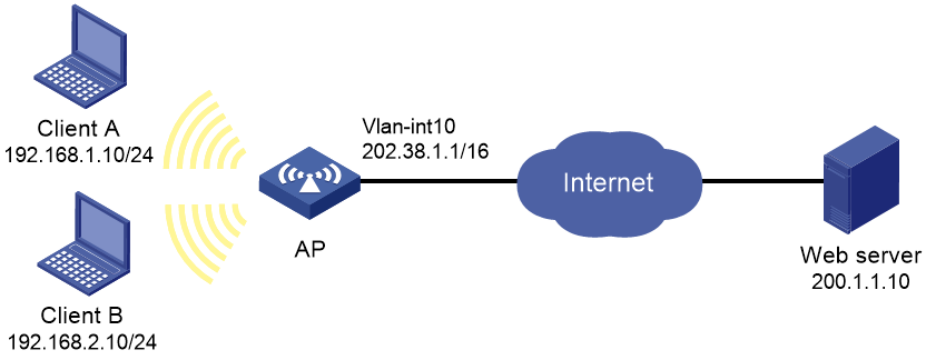
As shown in Figure 6, a company has a private subnet address 192.168.0.0/16 and two public IP addresses 202.38.1.2 and 202.38.1.3. Configure outbound dynamic NAT to allow only internal users on subnet 192.168.1.0/24 to access the Internet.
Procedure
# Assign IP addresses to interfaces. (Details not shown.)
# Configure address group 0, and add addresses 202.38.1.2 and 202.38.1.3 to the group.
<AP> system-view
[AP] nat address-group 0
[AP-address-group-0] address 202.38.1.2 202.38.1.3
[AP-address-group-0] quit
# Configure ACL 2000, and create a rule to permit packets only from subnet 192.168.1.0/24 to pass through.
[AP] acl basic 2000
[AP-acl-ipv4-basic-2000] rule permit source 192.168.1.0 0.0.0.255
[AP-acl-ipv4-basic-2000] quit
# Enable outbound dynamic PAT on VLAN-interface 10. The source IP addresses of the packets permitted by the ACL rule is translated into the addresses in address group 0.
[AP] interface vlan-interface 10
[AP-Vlan-interface10] nat outbound 2000 address-group 0
[AP-GigabitEthernet1/0/2] quit
Verifying the configuration
# Verify that Client A can access the WWW server, but Client B cannot. (Details not shown.)
# Display all NAT configuration and statistics.
[AP] display nat all
NAT address group information:
Totally 1 NAT address groups.
Address group ID: 0:
Port range: 1-65535
Address information:
Start address End address
202.38.1.2 202.38.1.3
NAT outbound information:
Totally 1 NAT outbound rules.
Interface: Vlan-interface10
ACL: 2000
Address group ID: 0
Port-preserved: N NO-PAT: N Reversible: N
Config status: Active
NAT logging:
Log enable : Disabled
Flow-begin : Disabled
Flow-end : Disabled
Flow-active : Disabled
Port-block-assign : Disabled
Port-block-withdraw : Disabled
Alarm : Disabled
NAT mapping behavior:
Mapping mode : Address and Port-Dependent
ACL : ---
Config status: Active
NAT ALG:
DNS : Enabled
FTP : Enabled
H323 : Enabled
ICMP-ERROR : Enabled
ILS : Enabled
MGCP : Enabled
NBT : Enabled
PPTP : Enabled
RTSP : Enabled
RSH : Enabled
SCCP : Enabled
SIP : Enabled
SQLNET : Enabled
TFTP : Enabled
XDMCP : Enabled
Static NAT load balancing: Disabled
# Display NAT session information generated when Client A accesses the WWW server.
[AP] display nat session verbose
Initiator:
Source IP/port: 192.168.1.10/52992
Destination IP/port: 200.1.1.10/2048
DS-Lite tunnel peer: -
VPN instance/VLAN ID/Inline ID: -/-/-
Protocol: ICMP(1)
Inbound interface: Vlan-interface1
Responder:
Source IP/port: 200.1.1.10/4
Destination IP/port: 202.38.1.3/0
DS-Lite tunnel peer: -
VPN instance/VLAN ID/Inline ID: -/-/-
Protocol: ICMP(1)
Inbound interface: Vlan-interface10
State: ICMP_REPLY
Application: INVALID
Rule ID: -/-/-
Rule name:
Start time: 2017-08-15 14:53:29 TTL: 12s
Initiator->Responder: 1 packets 84 bytes
Responder->Initiator: 1 packets 84 bytes
Total sessions found: 1