- Table of Contents
-
- 03-Layer 2—LAN Switching Configuration Guide
- 00-Preface
- 01-MAC address table configuration
- 02-Bulk interface configuration
- 03-Ethernet interface configuration
- 04-Ethernet link aggregation configuration
- 05-DRNI configuration
- 06-Port isolation configuration
- 07-VLAN configuration
- 08-MVRP configuration
- 09-Loopback, null, and inloopback interface configuration
- 10-QinQ configuration
- 11-VLAN mapping configuration
- 12-PBB configuration
- 13-Loop detection configuration
- 14-Spanning tree configuration
- 15-LLDP configuration
- 16-L2PT configuration
- 17-Service loopback group configuration
- 18-Cut-through Layer 2 forwarding configuration
- Related Documents
-
| Title | Size | Download |
|---|---|---|
| 03-Ethernet interface configuration | 291.92 KB |
Contents
Configuring Ethernet interfaces
Configuring a management Ethernet interface
Ethernet interface naming conventions
Restrictions and guidelines: Ethernet interface configuration
Ethernet interface configuration restrictions and guidelines on the S6800 switch series
Ethernet interface configuration restrictions and guidelines on the S6820 switch series
Ethernet interface configuration restrictions and guidelines on the S6860 switch series
Ethernet interface configuration restrictions and guidelines on the S6861 switch series
Configuring common Ethernet interface settings
Splitting a 40-GE interface and combining 10-GE breakout interfaces
Splitting a 100-GE interface and combining 10-GE breakout interfaces
Splitting a 100-GE interface and combining 25-GE breakout interfaces
Splitting a 100-GE interface and combining 40-GE interfaces
Configuring basic settings of an Ethernet interface
Configuring basic settings of an Ethernet subinterface
Configuring the link mode of an Ethernet interface
Configuring jumbo frame support
Configuring physical state change suppression on an Ethernet interface
Configuring dampening on an Ethernet interface
Enabling link flapping protection on an interface
Configuring generic flow control on an Ethernet interface
Configuring PFC deadlock detection
Setting the statistics polling interval
Enabling loopback testing on an Ethernet interface
Forcibly bringing up a fiber port
Setting the media type for an Ethernet interface
Enabling remote fault signal detection
Restoring the default settings for an interface
Configuring a Layer 2 Ethernet interface
Setting the MDIX mode of an Ethernet interface
Setting the interface connection distance
Configuring storm control on an Ethernet interface
Changing a Layer 2 Ethernet interface to an FC interface
Testing the cable connection of an Ethernet interface
Configuring the connection mode of an Ethernet interface
Enabling bridging on an Ethernet interface
Configuring a Layer 3 Ethernet interface or subinterface
Setting the MTU for an Ethernet interface or subinterface
Setting the MAC address of an Ethernet interface or subinterface
Enabling packet statistics collection on a Layer 3 Ethernet subinterface
Display and maintenance commands for Ethernet interfaces
Configuring Ethernet interfaces
About Ethernet interface
The Switch Series supports Ethernet interfaces, management Ethernet interfaces, Console interfaces, and USB interfaces. For the interface types and the number of interfaces supported by a switch model, see the installation guide.
This chapter describes how to configure management Ethernet interfaces and Ethernet interfaces.
Configuring a management Ethernet interface
About a management interface
A management interface uses an RJ-45/LC connector. You can connect the interface to a PC for software loading and system debugging, or connect it to a remote NMS for remote system management.
Each member device in an IRF system has a management Ethernet interface. For management link backup, perform the following tasks:
1. Connect your PC to the management Ethernet interface on the master device.
2. Connect the PC to a management Ethernet interface with the same interface number on a subordinate device.
The two management Ethernet interfaces operate as follows:
· When the IRF system has multiple management Ethernet interfaces, only the management Ethernet interface on the master device processes management traffic.
· When the management Ethernet interface on the master device fails, the management Ethernet interface on the subordinate device takes over to process management traffic.
· When the management Ethernet interface on the master device recovers, it takes over to process management traffic again.
Procedure
1. Enter system view.
system-view
2. Enter management Ethernet interface view.
interface M-GigabitEthernet interface-number
3. (Optional.) Set the interface description.
description text
The default setting is M-GigabitEthernet0/0/0 Interface.
4. (Optional.) Set the duplex mode for the management Ethernet interface.
duplex { auto | full | half }
By default, the duplex mode is auto for a management Ethernet interface.
5. (Optional.)_Set the speed for the management Ethernet interface.
speed { 10 | 100 | 1000 | auto }
By default, the speed is auto for a management Ethernet interface.
6. (Optional.) Shut down the interface.
shutdown
By default, the management Ethernet interface is up.
Ethernet interface naming conventions
The Ethernet interfaces are named in the format of interface type A/B/C. The letters that follow the interface type represent the following elements:
· A—IRF member ID. If the switch is not in an IRF fabric, A is 1 by default.
· B—Card slot number. 0 indicates the interface is a fixed interface of the switch. 1 indicates the interface is on expansion interface-card 1. 2 indicates the interface is on expansion interface-card 2.
· C—Port index.
For example, a 10-GE breakout interface split from a 40-GE interface is named in the format of interface type A/B/C:D. A/B/C is the interface number of the 40-GE interface. D is the number of the 10-GE interface, which is in the range of 1 to 4. For information about splitting a 40-GE interface, see "Splitting a 40-GE interface and combining 10-GE breakout interfaces."
Restrictions and guidelines: Ethernet interface configuration
Ethernet interface configuration restrictions and guidelines on the S6800 switch series
100-GE interface configuration restrictions and guidelines
A 100-GE interface on the S6800-54HF or S6800-54HT switch cannot be split into four breakout interfaces.
40-GE interface configuration restrictions and guidelines
On an S6800-32Q switch, interfaces FortyGigE 1/0/1 through FortyGigE 1/0/4 and FortyGigE 1/0/29 through FortyGigE 1/0/32 cannot be split.
When an LSWM124XGT2Q, LSWM124XG2Q, LSWM124XG2QL, or LSWM124XG2QFC expansion interface module is installed on an S6800-4C switch, 40-GE interfaces on the expansion interface module cannot be split into 10-GE breakout interfaces.
When an LSWM18CQMSEC expansion interface module is installed on an S6800-2C or S6800-4C switch, interfaces on the expansion interface module do not support QSFP28 transceiver modules or cables, and support only QSFP+ transceiver modules and cables.
When an LSWM18QC or LSWM18CQMSEC expansion interface module is installed on an S6800-4C switch, the last two 40-GE interfaces on the expansion interface module cannot be split into 10-GE breakout interfaces.
Ethernet interface configuration restrictions and guidelines on the S6820 switch series
40-GE interface configuration restrictions and guidelines
40-GE interfaces on the LSWM116Q expansion interface module cannot be split into 10-GE breakout interfaces.
25-GE interface configuration restrictions and guidelines
25-GE interfaces can operate at 25 Gbps, 10 Gbps, or 1 Gbps. 25-GE interfaces do not support autonegotiation for the speed and duplex mode. You must use the speed and duplex commands to ensure that the interfaces at both ends of a link operate at the same speed and duplex mode. An interface can come up only when the speed configured for the interface is the same as the speed of the transceiver module or cable installed in the interface. A 25-GE breakout interface can operate only at 25 Gbps.
Interfaces in the same group must have the same speed settings. When you modify the speed of an interface in a group, the modification takes effect on all interfaces in the group. When you modify the link mode (bridge or route) of an interface in a group or use the default command to restore the default settings for the interface, the speed will be restored to the default for the interface and the other interfaces in the group.
The CL72 and FEC protocols supported by 25-GE interfaces on the switch are still drafts. These protocols are not completely compatible for devices from different vendors. You can use the port cl72 enable and port fec enable commands on 25-GE interfaces of the switch to control the status of the two hardware protocols. Then, the switch can interoperate with devices from different vendors.
You must use the port media-type { copper | fiber } command to set the media type for the following interfaces:
· 25-GE interfaces Twenty-FiveGigE 1/0/1 through Twenty-FiveGigE 1/0/8 and Twenty-FiveGigE 1/0/49 through Twenty-FiveGigE 1/0/56 of an S6820-56HF switch.
· 25-GE interfaces on an LSWM124TG2H expansion interface module.
Set the media type to fiber for an interface that uses a transceiver module or fiber cable. Set the media type to copper for an interface that uses a copper cable. The media type of interfaces in the same group is the same. When you set the media type for any interface in a group, the setting is synchronized to the other interfaces in the group.
25-GE interfaces on the S6820 switch series are grouped as follows:
· For interfaces 1 through 24 and 33 through 56 on an S6820-56HF switch, four continuous interfaces starting from 1 or 33 are organized into one group.
· When you use the using twenty-fivegige command to split a 100-GE interface into four 25-GE breakout interfaces, the four breakout interfaces are organized into one group.
· For 25-GE interfaces on an LSWM124TG2H expansion interface module, four continuous interfaces starting from 1 are organized into one group.
10-GE interface configuration restrictions and guidelines
When an interface on an LSWM124XG2QL expansion interface module has a Gigabit SFP transceiver module installed, the interface does not support speed or duplex mode autonegotiation. You must execute the speed 1000 and duplex full commands on the interface and its peer interface.
Ethernet interface configuration restrictions and guidelines on the S6860 switch series
100-GE interface configuration restrictions and guidelines
A 100-GE interface on the S6860 switch series cannot be split into four breakout interfaces.
40-GE interface configuration restrictions and guidelines
By default, the last six interfaces on the S6860 switch series are 40-GE interfaces. Among these six interfaces, the odd-numbered interfaces (for example, 49, 51, and 53 or 25, 27, and 29) are in one group, and the even-numbered interfaces (for example, 50, 52, and 54 or 26, 28, and 30) are in one group. Executing the using hundredgige command on any 40-GE interface in each group combines the three 40-GE interfaces in the group into one 100-GE interface. Then, only the last two 100-GE interfaces (53 and 54, or 29 and 30) are available. To restore the 100-GE interface to 40-GE interfaces, execute the using fortygige command on the 100-GE interface.
If one of the last six 40-GE interfaces on the S6860 switch series is split into four 10-GE breakout interfaces, interfaces in the same group as the interface cannot be combined into 100-GE interfaces.
When a 40-GE interface is configured as an IRF physical interface, you cannot execute the using hundredgige command on the interface or interfaces in the same group as the interface.
When a 100-GE interface is configured as an IRF physical interface, you cannot execute the using fortygige command on the interface.
10-GE interface configuration restrictions and guidelines
On an S6860-54HF switch, interfaces 29 through 36 do not support Gigabit SFP transceiver modules.
On an S6860-54HT switch, interfaces 29 through 36 support only the 10000 and auto keywords of the speed command. When the speed is set to autonegotiation for one of these interfaces, the interface can only negotiate the speed as 10000 Mbps.
Ethernet interface configuration restrictions and guidelines on the S6861 switch series
On an S6861-54QF switch, interfaces 29 through 36 do not support Gigabit SFP transceiver modules.
On an S6861-54QT switch, interfaces 29 through 36 support only the 10000 and auto keywords of the speed command. When the speed is set to autonegotiation for one of these interface, the interface can only negotiate the speed as 10000 Mbps.
Configuring common Ethernet interface settings
This section describes the settings common to Layer 2 Ethernet interfaces, Layer 3 Ethernet interfaces, and Layer 3 Ethernet subinterfaces. For more information about the settings specific to Layer 2 Ethernet interfaces, see "Configuring a Layer 2 Ethernet interface." For more information about the settings specific to Layer 3 Ethernet interfaces or subinterfaces, see "Configuring a Layer 3 Ethernet interface or subinterface."
Splitting a 40-GE interface and combining 10-GE breakout interfaces
About 40-GE interface splitting and 10-GE breakout interface combining
You can use a 40-GE interface as a single interface. To improve port density, reduce costs, and improve network flexibility, you can also split a 40-GE interface into four 10-GE breakout interfaces. The 10-GE breakout interfaces support the same configuration and attributes as common 10-GE interfaces, except that they are numbered differently.
For example, you can split 40-GE interface FortyGigE 1/0/1 into four 10-GE breakout interfaces Ten-GigabitEthernet 1/0/1:1 through Ten-GigabitEthernet 1/0/1:4.
If you need higher bandwidth on a single interface, you can combine the four 10-GE breakout interfaces into a 40-GE interface.
Restrictions and guidelines for 40-GE interface splitting and 10-GE breakout interface combining
· A 40-GE interface split into four 10-GE breakout interfaces must use a dedicated 1-to-4 cable. After you combine the four 10-GE breakout interfaces, replace the dedicated 1-to-4 cable with a dedicated 1-to-1 cable or a 40-GE transceiver module. For more information about the cable or transceiver module, see the installation guides.
· Device reboot is not required for this feature to take effect. To view information about the breakout or combined interfaces, execute the display interface brief command.
· An interface with any of the following configurations cannot be split:
¡ IRF physical interface.
¡ Service loopback group member.
¡ Reflector port for mirroring.
¡ Forcibly brought up.
Splitting a 40-GE interface into four 10-GE breakout interfaces
1. Enter system view.
system-view
2. Enter 40-GE interface view.
interface interface-type interface-number
3. Split the 40-GE interface into four 10-GE breakout interfaces.
using tengige
By default, a 40-GE interface is not split and operates as a single interface.
Combining four 10-GE breakout interfaces into a 40-GE interface
1. Enter system view.
system-view
2. Enter the view of any 10-GE breakout interface.
interface interface-type interface-number
3. Combine the four 10-GE breakout interfaces into a 40-GE interface.
using fortygige
By default, a 10-GE breakout interface operates as a single interface.
Splitting a 100-GE interface and combining 10-GE breakout interfaces
About 100-GE interface splitting and 10-GE breakout interface combining
You can use a 100-GE interface as a single interface. To improve port density, reduce costs, and improve network flexibility, you can split a 100-GE interface with a split-capable transceiver module installed into four 10-GE breakout interfaces. The 10-GE breakout interfaces support the same configuration and attributes as common 10-GE interfaces, except that they are numbered differently. For example, you can split 100-GE interface HundredGigE 1/0/1 into four 10-GE breakout interfaces Ten-GigabitEthernet1/0/1:1 through Ten-GigabitEthernet1/0/1:4.
If you need higher bandwidth on a single interface, you can combine the multiple 10-GE breakout interfaces into a 100-GE interface.
Hardware and feature compatibility
This feature is not supported on the S6800, S6860, or S6861 switch series.
Restrictions and guidelines for 100-GE interface splitting and 10-GE breakout interface combining
· A 100-GE interface split into multiple 10-GE breakout interfaces must use a dedicated cable. After you combine the multiple 10-GE breakout interfaces, replace the dedicated cable with a dedicated 1-to-1 cable or a 100-GE transceiver module. For more information about the cable or transceiver module, see the installation guides.
· Device reboot is not required for this feature to take effect. To view information about the breakout or combined interfaces, execute the display interface brief command.
· An interface with any of the following configurations cannot be split:
¡ IRF physical interface.
¡ Service loopback group member.
¡ Reflector port for mirroring.
¡ Forcibly brought up.
Splitting a 100-GE interface into four 10-GE breakout interfaces
1. Enter system view.
system-view
2. Enter 100-GE interface view.
interface interface-type interface-number
3. Split the 100-GE interface into four 10-GE breakout interfaces.
using tengige
By default, a 100-GE interface is not split and operates as a single interface.
Combining four 10-GE breakout interfaces into a 100-GE interface
1. Enter system view.
system-view
2. Enter the view of any 10-GE breakout interface.
interface interface-type interface-number
3. Combine the four 10-GE breakout interfaces into a 100-GE interface.
using hundredgige
By default, a 10-GE breakout interface operates as a single interface.
Splitting a 100-GE interface and combining 25-GE breakout interfaces
About 100-GE interface splitting and 25-GE breakout interface combining
You can use a 100-GE interface as a single interface. To improve port density, reduce costs, and improve network flexibility, you can also split a 100-GE interface into four 25-GE breakout interfaces. The 25-GE breakout interfaces support the same configuration and attributes as common 25-GE interfaces, except that they are numbered differently.
For example, you can split 100-GE interface HundredGigE 1/0/1 into four 25-GE breakout interfaces Twenty-FiveGigE 1/0/1:1 through Twenty-FiveGigE 1/0/1:4.
If you need higher bandwidth on a single interface, you can combine the four 25-GE breakout interfaces into a 100-GE interface.
Hardware and feature compatibility
Hardware and feature compatibility
This feature is not supported on the S6800, S6860, or S6861 switch series.
Restrictions and guidelines for 100-GE interface splitting and 25-GE breakout interface combining
· A 100-GE interface split into four 25-GE breakout interfaces must use a dedicated 1-to-4 cable. After you combine the four 25-GE breakout interfaces, replace the dedicated 1-to-4 cable with a dedicated 1-to-1 cable or a 100-GE transceiver module. For more information about the cable or transceiver module, see the installation guides.
· Device reboot is not required for this feature to take effect. To view information about the breakout or combined interfaces, execute the display interface brief command.
· An interface with any of the following configurations cannot be split:
¡ IRF physical interface.
¡ Service loopback group member.
¡ Reflector port for mirroring.
¡ Forcibly brought up.
Splitting a 100-GE interface into four 25-GE breakout interfaces
1. Enter system view.
system-view
2. Enter 100-GE interface view.
interface interface-type interface-number
3. Split the 100-GE interface into four 25-GE breakout interfaces.
using twenty-fivegige
By default, a 100-GE interface is not split and operates as a single interface.
Combining four 25-GE breakout interfaces into a 100-GE interface
1. Enter system view.
system-view
2. Enter the view of any 25-GE breakout interface.
interface interface-type interface-number
3. Combine the four 25-GE breakout interfaces into a 100-GE interface.
using hundredgige
By default, a 25-GE breakout interface operates as a single interface.
Splitting a 100-GE interface and combining 40-GE interfaces
About this task
On the S6860 switch series, the last six 40-GE interfaces are grouped as follows:
· Odd-numbered interfaces (for example, 49, 51, and 53, or 25, 27, and 29) are in one group.
· Even-numbered interfaces (for example, 50, 52, and 54, or 26, 28, and 30) are in one group.
When you execute the using hundredgige command on any of these 40-GE interfaces, 40-GE interfaces in the same group are combined into a 100-GE interface.
If you need higher bandwidth, you can combine 40-GE interfaces into 100-GE interfaces.
Hardware and feature compatibility
This feature is not supported on the S6800, S6820, or S6861 switch series.
Restrictions and guidelines
After configuring this feature, you do not need to reboot the device. To view the split or combined interfaces, execute the display interface brief command.
An interface with any of the following setting cannot be combined or split:
· IRF physical interface.
· Service loopback group member.
· Reflector port for mirroring.
· Forcibly bringing up a fiber port.
Combining three 40-GE interfaces into a 100-GE interface
1. Enter system view.
system-view
2. Enter 40-GE interface view.
interface fortygige interface-number
3. Combine the three 40-GE interfaces in the same group into a 100-GE interface.
using hundredgige
By default, a 40-GE interface operates as a single interface.
Splitting a 100-GE interface into three 40-GE interfaces
1. Enter system view.
system-view
2. Enter the view of the 100-GE interface combined from three 40-GE interfaces.
interface hundredgige interface-number
3. Split the 100-GE interface into three 40-GE interfaces.
using fortygige
Configuring basic settings of an Ethernet interface
About Ethernet interface basic settings
You can configure an Ethernet interface to operate in one of the following duplex modes:
· Full-duplex mode—The interface can send and receive packets simultaneously.
· Half-duplex mode—The interface can only send or receive packets at a given time.
· Autonegotiation mode—The interface negotiates a duplex mode with its peer.
You can set the speed of an Ethernet interface or enable it to automatically negotiate a speed with its peer.
Restrictions and guidelines
The shutdown, port up-mode, and loopback commands are mutually exclusive.
Procedure
1. Enter system view.
system-view
2. Enter Ethernet interface view.
interface interface-type interface-number
3. Set the description for the Ethernet interface.
description text
The default setting is interface-name Interface. For example, Ten-GigabitEthernet1/0/1 Interface.
4. Set the duplex mode for the Ethernet interface.
duplex { auto | full }
By default, the duplex mode is auto for Ethernet interfaces.
5. Set the speed for the Ethernet interface.
speed { 10 | 100 | 1000 | 10000 | 25000 | 40000 | 100000 | auto }
By default, an Ethernet interface negotiates a speed with its peer.
6. Set the expected bandwidth for the Ethernet interface.
bandwidth bandwidth-value
By default, the expected bandwidth (in kbps) is the interface baud rate divided by 1000.
7. Bring up the Ethernet interface.
undo shutdown
By default, Ethernet interfaces are in up state.
Configuring basic settings of an Ethernet subinterface
Restrictions and guidelines for Ethernet subinterface basic settings
· The shutdown, port up-mode, and loopback commands are mutually exclusive.
· The shutdown command cannot be configured on an Ethernet interface in a loopback test.
Procedure
1. Enter system view.
system-view
2. Create an Ethernet subinterface.
interface interface-type interface-number.subnumber
3. Set the description for the Ethernet subinterface.
description text
The default setting is interface-name Interface. For example, Ten-GigabitEthernet1/0/1.1 Interface.
4. Set the expected bandwidth for the Ethernet subinterface.
bandwidth bandwidth-value
By default, the expected bandwidth (in kbps) is the interface baud rate divided by 1000.
5. Bring up the Ethernet subinterface.
undo shutdown
By default, Ethernet subinterfaces are in up state.
Configuring the link mode of an Ethernet interface
About the link mode of an Ethernet interface
Interfaces on the device can operate either as Layer 2 or Layer 3 Ethernet interfaces. You can use commands to set the link mode to bridge or route.
Restrictions and guidelines
After you change the link mode of an Ethernet interface, all commands (except the speed, shutdown ) on the Ethernet interface are restored to their defaults in the new link mode.
In an IRF 3.1 system, interfaces on a PEX cannot operate in Layer 3 mode.
Procedure
1. Enter system view.
system-view
2. Enter Ethernet interface view.
interface interface-type interface-number
3. Configure the link mode of the Ethernet interface.
port link-mode { bridge | route }
By default, all Ethernet interfaces on the device operate in bridge mode.
Configuring jumbo frame support
About jumbo frame
Jumbo frames are frames larger than 1536 bytes and are typically received by an Ethernet interface during high-throughput data exchanges, such as file transfers.
The Ethernet interface processes jumbo frames in the following ways:
· When the Ethernet interface is configured to deny jumbo frames (by using the undo jumboframe enable command), the Ethernet interface discards jumbo frames.
· When the Ethernet interface is configured with jumbo frame support, the Ethernet interface performs the following operations:
¡ Processes jumbo frames within the specified length.
¡ Discards jumbo frames that exceed the specified length.
Procedure
1. Enter system view.
system-view
2. Enter Ethernet interface view.
interface interface-type interface-number
3. Configure jumbo frame support.
jumboframe enable [ size ]
By default:
¡ On the S6800, S6860, and S6861 switch series, an Ethernet interface allows jumbo frames within 10000 bytes to pass through.
¡ On the S6820 switch series, an Ethernet interface allows jumbo frames within 9416 bytes to pass through.
If you set the size argument multiple times, the most recent configuration takes effect.
Configuring physical state change suppression on an Ethernet interface
About physical state change suppression
The physical link state of an Ethernet interface is either up or down. Each time the physical link of an interface comes up or goes down, the interface immediately reports the change to the CPU. The CPU then performs the following operations:
· Notifies the upper-layer protocol modules (such as routing and forwarding modules) of the change for guiding packet forwarding.
· Automatically generates traps and logs to inform users to take the correct actions.
To prevent frequent physical link flapping from affecting system performance, configure physical state change suppression. You can configure this feature to suppress only link-down events, only link-up events, or both. If an event of the specified type still exists when the suppression interval expires, the system reports the event to the CPU.
Restrictions and guidelines
Do not enable this feature on an interface that has RRPP, spanning tree protocols, or Smart Link enabled.
You can configure different suppression intervals for link-up and link-down events.
If you execute the link-delay command multiple times on an interface, the following rules apply:
· You can configure the suppression intervals for link-up and link-down events separately.
· If you configure the suppression interval multiple times for link-up or link-down events, the most recent configuration takes effect.
The link-delay, dampening, and port link-flap protect enable commands are mutually exclusive on an Ethernet interface.
Procedure
1. Enter system view.
system-view
2. Enter Ethernet interface view.
interface interface-type interface-number
3. Configure physical state change suppression.
link-delay { down | up } [ msec ] delay-time
By default, each time the physical link of a port goes up or comes down, the interface immediately reports the change to the CPU.
Configuring dampening on an Ethernet interface
About dampening
The interface dampening feature uses an exponential decay mechanism to prevent excessive interface flapping events from adversely affecting routing protocols and routing tables in the network. Suppressing interface state change events protects the system resources.
If an interface is not dampened, its state changes are reported. For each state change, the system also generates an SNMP trap and log message.
After a flapping interface is dampened, it does not report its state changes to the CPU. For state change events, the interface only generates SNMP trap and log messages.
Parameters
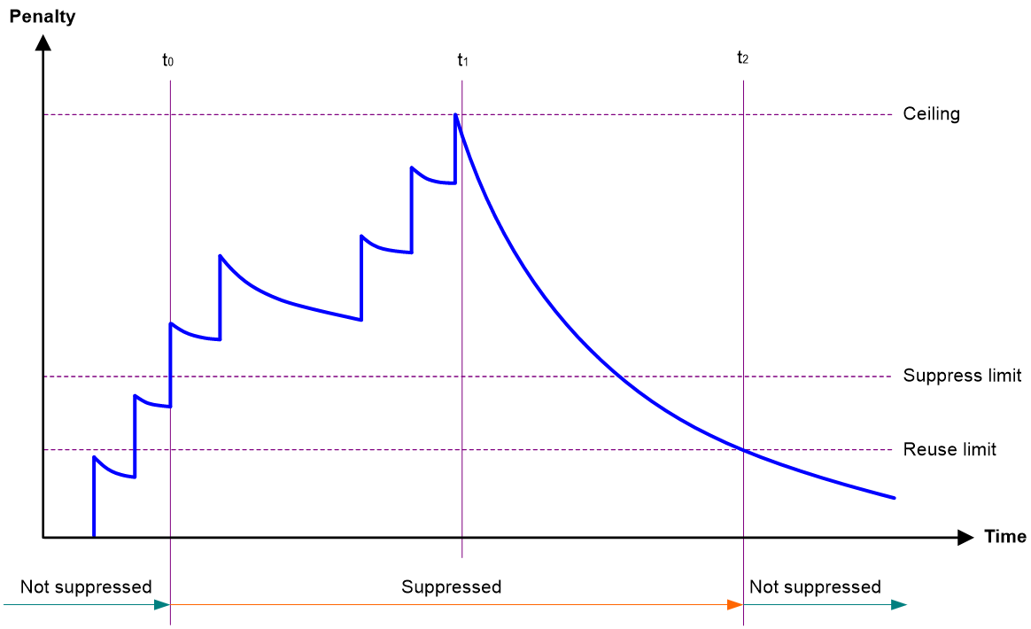
· Penalty—The interface has an initial penalty of 0. When the interface flaps, the penalty increases by 1000 for each down event until the ceiling is reached. It does not increase for up events. When the interface stops flapping, the penalty decreases by half each time the half-life timer expires until the penalty drops to the reuse threshold.
· Ceiling—The penalty stops increasing when it reaches the ceiling.
· Suppress-limit—The accumulated penalty that triggers the device to dampen the interface. In dampened state, the interface does not report its state changes to the CPU. For state change events, the interface only generates SNMP traps and log messages.
· Reuse-limit—When the accumulated penalty decreases to this reuse threshold, the interface is not dampened. Interface state changes are reported to the upper layers. For each state change, the system also generates an SNMP trap and log message.
· Decay—The amount of time (in seconds) after which a penalty is decreased.
· Max-suppress-time—The maximum amount of time the interface can be dampened. If the penalty is still higher than the reuse threshold when this timer expires, the penalty stops increasing for down events. The penalty starts to decrease until it drops below the reuse threshold.
When configuring the dampening command, follow these rules to set the values mentioned above:
· The ceiling is equal to 2(Max-suppress-time/Decay) × reuse-limit. It is not user configurable.
· The configured suppress limit is lower than or equal to the ceiling.
· The ceiling is lower than or equal to the maximum suppress limit supported.
Figure 1 shows the change rule of the penalty value. The lines t0 and t2 indicate the start time and end time of the suppression, respectively. The period from t0 to t2 indicates the suppression period, t0 to t1 indicates the max-suppress-time, and t1 to t2 indicates the complete decay period.
Figure 1 Change rule of the penalty value
Restrictions and guidelines
· The dampening, link-delay, and port link-flap protect enable commands are mutually exclusive on an interface.
· The dampening command does not take effect on the administratively down events. When you execute the shutdown command, the penalty restores to 0, and the interface reports the down event to the upper-layer protocols.
· Do not enable the dampening feature on an interface with RRPP, MSTP, or Smart Link enabled.
Procedure
1. Enter system view.
system-view
2. Enter Ethernet interface view.
interface interface-type interface-number
3. Enable dampening on the interface.
dampening [ half-life reuse suppress max-suppress-time ]
By default, interface dampening is disabled on Ethernet interfaces.
Enabling link flapping protection on an interface
About link flapping protection
Link flapping on an interface changes network topology and increases the system overhead. For example, in an active/standby link scenario, when interface status on the active link changes between UP and DOWN, traffic switches between active and standby links. To solve this problem, configure this feature on the interface.
With this feature enabled on an interface, when the interface goes down, the system enables link flapping detection. During the link flapping detection interval, if the number of detected flaps reaches or exceeds the link flapping detection threshold, the system shuts down the interface.
Restrictions and guidelines
This feature takes effect only if it is configured in both the system view and interface view.
The dampening, link-delay, and port link-flap protect enable commands are mutually exclusive on an Ethernet interface.
To bring up an interface that has been shut down by link flapping protection, execute the undo shutdown command.
In the display interface command output, the Link-Flap DOWN value of the Current state field indicates that the interface has been shut down by link flapping protection.
Procedure
1. Enter system view.
system-view
2. Enable link flapping protection globally.
link-flap protect enable
By default, link flapping protection is disabled globally.
3. Enter Ethernet interface view.
interface interface-type interface-number
4. Enable link flapping protection on the Ethernet interface.
port link-flap protect enable [ interval interval | threshold threshold ] *
By default, link flapping protection is disabled on an Ethernet interface.
Configuring fast retrain
About fast retrain
Copper Ethernet ports negotiate parameters through electric signals to determine the up/down status. In an actual network, if a copper port is in a high-frequency or low-frequency environment, the electrical signals will be affected. As a result, the negotiated status might be incorrect. You can enable or disable fast retrain on a copper port to adjust the frequency of electrical signals transmitted by the copper port to improve the anti-attenuation and anti-inference capabilities of the interface.
Enabling fast retrain on a copper port enables the port to perform negotiation by using high-frequency electrical signals, which improves the anti-attenuation capability of the copper port. Disabling fast retrain on a copper port enables the port to perform negotiation by using low-frequency electrical signals, which improves the anti-interference capability of the copper port.
Hardware and feature compatibility
Hardware and feature compatibility
This feature is supported only on the copper ports of LSWM124XGT2Q expansion interface modules installed on the S6800 and S6820 switch series.
Procedure
1. Enter system view.
system-view
2. Enter Ethernet interface view.
interface interface-type interface-number
3. Enable fast retrain.
port fast-retrain enable
By default, fast retrain is disabled.
Configuring storm suppression
About storm suppression
The storm suppression feature ensures that the size of a particular type of traffic (broadcast, multicast, or unknown unicast traffic) does not exceed the threshold on an interface. When the broadcast, multicast, or unknown unicast traffic on the interface exceeds this threshold, the system discards packets until the traffic drops below this threshold.
Both storm suppression and storm control can suppress storms on an interface. Storm suppression uses the chip to suppress traffic. Storm suppression has less impact on the device performance than storm control, which uses software to suppress traffic.
Restrictions and guidelines
· For the traffic suppression result to be determined, do not configure storm control together with storm suppression for the same type of traffic. For more information about storm control, see "Configuring storm control on an Ethernet interface."
· When you configure the suppression threshold in kbps, the actual suppression threshold might be different from the configured one as follows:
¡ If the configured value is smaller than 64, the value of 64 takes effect.
¡ If the configured value is greater than 64 but not an integer multiple of 64, the integer multiple of 64 that is greater than and closest to the configured value takes effect.
For the suppression threshold that takes effect, see the prompt on the device.
· Set the same type of thresholds for each interface.
Procedure
system-view
2. Enter Ethernet interface view.
interface interface-type interface-number
3. Enable broadcast suppression and set the broadcast suppression threshold.
broadcast-suppression { ratio | pps max-pps | kbps max-kbps }
By default, broadcast suppression is disabled.
4. Enable multicast suppression and set the multicast suppression threshold.
multicast-suppression { ratio | pps max-pps | kbps max-kbps } [ unknown ]
By default, multicast suppression is disabled.
5. Enable unknown unicast suppression and set the unknown unicast suppression threshold.
unicast-suppression { ratio | pps max-pps | kbps max-kbps }
By default, unknown unicast suppression is disabled.
Configuring generic flow control on an Ethernet interface
About generic flow control
To avoid dropping packets on a link, you can enable generic flow control at both ends of the link. When traffic congestion occurs at the receiving end, the receiving end sends a flow control (Pause) frame to ask the sending end to suspend sending packets. Generic flow control includes the following types:
· TxRx-mode generic flow control—Enabled by using the flow-control command. With TxRx-mode generic flow control enabled, an interface can both send and receive flow control frames:
¡ When congestion occurs, the interface sends a flow control frame to its peer.
¡ When the interface receives a flow control frame from its peer, it suspends sending packets to its peer.
· Rx-mode generic flow control—Enabled by using the flow-control receive enable command. With Rx-mode generic flow control enabled, an interface can receive flow control frames, but it cannot send flow control frames:
¡ When congestion occurs, the interface cannot send flow control frames to its peer.
¡ When the interface receives a flow control frame from its peer, it suspends sending packets to its peer.
To handle unidirectional traffic congestion on a link, configure the flow-control receive enable command at one end and the flow-control command at the other end. To enable both ends of a link to handle traffic congestion, configure the flow-control command at both ends.
Procedure
1. Enter system view.
system-view
2. Enter Ethernet interface view.
interface interface-type interface-number
3. Enable generic flow control.
¡ Enable TxRx-mode generic flow control.
flow-control
¡ Enable Rx-mode generic flow control.
flow-control receive enable
By default, generic flow control is disabled on an Ethernet interface.
Configuring PFC
About PFC
When congestion occurs in the network, the local device notifies the peer to stop sending packets carrying the specified 802.1p priority if all of the following conditions exist:
· Both the local end and the remote end have priority-based flow control (PFC) enabled.
· Both the local end and the remote end have the priority-flow-control no-drop dot1p command configured.
· The specified 802.1p priority is in the 802.1p priority list specified by the dot1p-list argument.
· The local end receives a packet carrying the specified 802.1p priority.
Restrictions and guidelines
· You can configure PFC in both system view and Ethernet interface view. If you configure PFC in system view and Ethernet interface view multiple times, the most recent configuration takes effect.
· For IRF and other protocols to operate correctly, as a best practice, do not enable PFC for 802.1p priorities 0, 6, and 7.
· To perform PFC on an IRF port, configure PFC on the IRF port and the IRF physical ports that are bound to the IRF port. For information about IRF, see IRF configuration Guide.
· To perform PFC in an overlay network, execute the qos trust tunnel-dot1p command. For information about the overlay network, see VXLAN Configuration Guide. For information about the qos trust tunnel-dot1p command, see ACL and QoS Command Reference.
· To avoid packet loss, apply the same PFC configuration to all interfaces that the packets pass through.
· If you do not enable PFC on an interface, the interface can receive but cannot process PFC pause frames. To make PFC take effect, you must enable PFC on both ends.
· If you configure the flow control or flow-control receive enable command on a PFC-enabled interface, the following rules apply:
¡ The PFC configuration takes effect.
¡ The configuration of the flow control or flow-control receive enable command is ignored.
¡ The flow control or flow-control receive enable command takes effect on the interface only when PFC is disabled on it.
Configuring PFC in system view
1. Enter system view.
system-view
2. Enable PFC on all Ethernet interfaces.
priority-flow-control enable
By default, PFC is disabled on all Ethernet interfaces.
3. Enable PFC for 802.1p priorities on all Ethernet interfaces.
priority-flow-control no-drop dot1p dot1p-list
By default, PFC is disabled for all 802.1p priorities on all Ethernet interfaces.
Configuring PFC in Ethernet interface view
1. Enter system view.
system-view
2. Enter Ethernet interface view.
interface interface-type interface-number
3. Enable PFC on the Ethernet interface.
priority-flow-control enable
By default, PFC is disabled on an Ethernet interface.
4. Enable PFC for 802.1p priorities.
priority-flow-control no-drop dot1p dot1p-list
By default, PFC is disabled for all 802.1p priorities.
Setting PFC thresholds
About PFC thresholds
The storage spaces for an interface include the following types:
· Headroom storage space.
· Shared storage space.
· Guaranteed storage space.
Setting PFC thresholds enables flexible control over PFC and can make good use of the storage spaces. The device supports the following PFC thresholds:
· Headroom buffer threshold—Maximum number of cell resources that can be used by packets with a specific 802.1p priority value in a headroom storage space. An interface drops received packets once this threshold is reached.
· Back pressure frame triggering threshold—Maximum number of cell resources that can be used by packets with a specific 802.1p priority value in a shared storage space. PFC is triggered once this threshold is reached. The back pressure frame triggering threshold includes the following types:
¡ Dynamic back pressure frame triggering threshold—Maximum cell resources set in percentage.
¡ Static back pressure frame triggering threshold—Maximum cell resources set in an absolute value.
· Offset between the back pressure frame stopping threshold and triggering threshold—When the number of cell resources used by packets with a specific 802.1p priority value decreases by this offset after PFC is triggered, PFC will be stopped.
· PFC reserved threshold—Number of cell resources reserved for packets with a specific 802.1p priority value in a guaranteed storage space.
Restrictions and guidelines
|
|
WARNING! After PFC is enabled for 802.1p priorities, the PFC thresholds use the default values, which are adequate in typical network environments. As a practice, change the thresholds only when necessary. |
You must enable PFC for 802.1p priorities before setting the PFC thresholds.
If you cancel PFC threshold settings on an interface, the PFC thresholds are restored to the state when only the priority-flow-control no-drop dot1p command is executed.
This feature does not support preprovisioning. For more information about preprovisioning, see Fundamentals Configuration Guide.
Procedure
1. Enter system view.
system-view
2. Set the maximum number of cell resources in a headroom storage space.
priority-flow-control poolID pool-number headroom headroom-number
The poolID keyword is not supported on the S6800, S6860, and S6861 switch series.
By default, the maximum number of cell resources in a headroom storage space is 12288.
3. Enter Ethernet interface view.
interface interface-type interface-number
4. Enable PFC for the specified 802.1p priority values on the Ethernet interface.
priority-flow-control no-drop dot1p dot1p
By default, PFC is disabled for all 802.1p priority values on an interface.
5. Set the headroom buffer threshold.
priority-flow-control dot1p dot1p headroom headroom-number
By default:
¡ On the S6800, S6860, and S6861 switch series, the headroom buffer threshold is 4000 for 40-GE interfaces and 1000 for 10-GE interfaces.
¡ On the S6820 switch series, the headroom buffer threshold is 9984.
6. Set the back pressure frame triggering threshold.
¡ Set the dynamic back pressure frame triggering threshold.
priority-flow-control dot1p dot1p ingress-buffer dynamic ratio
By default, no dynamic back pressure frame triggering thresholds are set.
¡ Set the static back pressure frame triggering threshold.
priority-flow-control dot1p dot1p ingress-buffer static threshold
By default:
- On the S6800, S6860, and S6861 switch series, the static back pressure frame triggering threshold is 1000 for 40-GE interfaces and 250 for 10-GE interfaces.
- On the S6820 switch series, the headroom buffer threshold is 512.
7. Set the offset between the back pressure frame stopping threshold and triggering threshold.
priority-flow-control dot1p dot1p ingress-threshold-offset offset-number
By default:
¡ On the S6800, S6860, and S6861 switch series, the offset between the back pressure frame stopping threshold and triggering threshold is 204 for 40-GE interfaces and 51 for 10-GE interfaces.
¡ On the S6820 switch series, the headroom buffer threshold is 48.
8. Set the PFC reserved threshold.
priority-flow-control dot1p dot1p reserved-buffer reserved-number
By default, the PFC reserved threshold is 15.
Configuring PFC deadlock detection
About PFC deadlock detection
The device enters the PFC deadlock state if all of the following conditions exist on an interface:
· PFC for 802.1p priorities is enabled by using the priority-flow-control and priority-flow-control no-drop dot1p commands.
· Packets carrying the specified 802.1p priority are transmitted in a loop.
· No packets in the data buffer can be forwarded.
This feature periodically detects whether the device is in the PFC deadlock state. If an interface is always in the PFC XOFF state within the PFC deadlock detection interval, the device enters the PFC deadlock state. If PFC deadlock detection is recovered in automatic mode, the device automatically releases the deadlock state and recovers PFC and PFC deadlock detection after the delay timer expires. During the delay timer period, the device disables PFC and PFC deadlock detection on the interface, so that packets can be forwarded properly.
After the PFC deadlock state is released, the PFC deadlock detection feature can be recovered on the interface in automatic or manual mode. Recovering this feature enables the PFC feature again at the same time. Use the automatic recovery mode when no serious failures occur.
When a packet loop cannot be eliminated and the device enters PFC deadlock state frequently, manually recover PFC deadlock detection on the interface as follows:
1. Perform troubleshooting and set the manual recovery mode for PFC deadlock detection.
2. Execute the priority-flow-control deadlock recover command to recover the PFC deadlock detection and PFC features.
Restrictions and guidelines
The specified CoS value must be within the 802.1p priority list specified by using the priority-flow-control no-drop dot1p command. To view the 802.1p priority for each CoS value, execute the display qos map-table dot1p-lp command.
Prerequisites
Before you configure PFC deadlock detection on an Ethernet interface, complete the following tasks:
· Enable PFC in auto mode or forcibly on the Ethernet interface.
· Enable PFC for 802.1p priorities on the Ethernet interface.
Procedure
1. Enter system view.
system-view
2. Set the precision for the PFC deadlock detection timer.
priority-flow-control deadlock precision { high | normal | low }
By default, the PFC deadlock detection timer uses normal precision.
3. Set the PFC deadlock detection interval for the specified CoS value.
priority-flow-control deadlock cos cos-value interval interval
By default, the PFC deadlock detection interval is not set.
4. Configure the delay timer for PFC deadlock detection automatic recovery.
priority-flow-control deadlock auto-recover cos cos-value delay delay-time
By default, the delay timer for PFC deadlock detection automatic recovery is not configured.
5. Configure the action to take on packets during the delay timer period for PFC deadlock automatic recovery.
priority-flow-control deadlock auto-recover action { discard | forwarding }
By default, the device forwards received data packets during the delay timer period for PFC deadlock detection automatic recovery.
6. Configure the upper threshold for PFC deadlock times during the specified period.
priority-flow-control deadlock threshold cos cos-value period period count count
By default, the upper threshold for PFC deadlock times during the specified period is not configured.
7. Enter Ethernet interface view.
interface interface-type interface-number
8. Set the recovery mode for PFC deadlock detection on the Ethernet interface.
priority-flow-control deadlock recover-mode { auto | manual }
By default, PFC deadlock detection recovers in automatic mode.
9. Enable PFC deadlock detection on the Ethernet interface.
priority-flow-control deadlock enable
By default, PFC deadlock detection is disabled.
10. (Optional.) Recover PFC deadlock detection on the Ethernet interface.
priority-flow-control deadlock recover
You can use only this command to recover PFC deadlock detection if you set the manual recovery mode for PFC deadlock detection on the Ethernet interface.
Setting the statistics polling interval
About statistics polling interval
To display the interface statistics collected in the last statistics polling interval, use the display interface command. To clear the interface statistics, use the reset counters interface command.
Restrictions and guidelines for setting the statistics polling interval
Setting the statistics polling interval in Ethernet interface view
1. Enter system view.
system-view
2. Enter Ethernet interface view.
interface interface-type interface-number
3. Set the statistics polling interval for the Ethernet interface.
flow-interval interval
By default, the statistics polling interval is 300 seconds.
Enabling loopback testing on an Ethernet interface
About loopback testing
Perform this task to determine whether an Ethernet link works correctly.
Loopback testing includes the following types:
· Internal loopback testing—Tests the device where the Ethernet interface resides. The Ethernet interface sends outgoing packets back to the local device. If the device fails to receive the packets, the device fails.
· External loopback testing—Tests the hardware function of the Ethernet interface. The Ethernet interface sends outgoing packets to the local device through a self-loop plug. If the device fails to receive the packets, the hardware function of the Ethernet interface fails.
Restrictions and guidelines
· After you enable this feature on an Ethernet interface, the interface does not forward data traffic.
· An Ethernet interface in a loopback test cannot correctly forward data packets.
· You cannot perform a loopback test on Ethernet interfaces manually brought down (displayed as in ADM or Administratively DOWN state).
· The speed, duplex, mdix-mode, and shutdown commands cannot be configured on an Ethernet interface in a loopback test.
· After you enable this feature on an Ethernet interface, the Ethernet interface switches to full duplex mode. After you disable this feature, the Ethernet interface restores to its duplex setting.
· If you enable this feature on an interface in an IRF 3.1 system, the following rules apply:
¡ If the interface is on a parent device, loopback testing does not stop before you use the undo command to disable this feature.
¡ If the interface is on a PEX, the interface automatically disables this feature after one round of loopback testing is completed.
For more information about parent devices and PEXs, see IRF Configuration Guide.
Procedure
1. Enter system view.
system-view
2. Enter Ethernet interface view.
interface interface-type interface-number
3. Enable loopback testing.
loopback{ external | internal }
Forcibly bringing up a fiber port
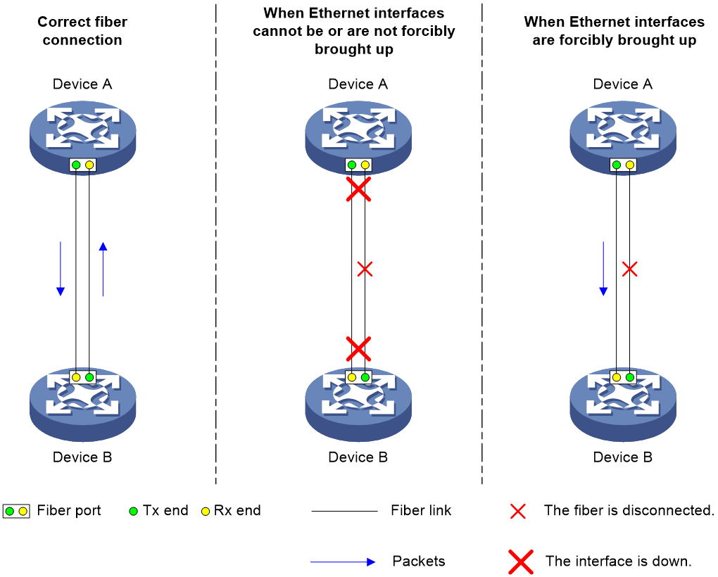
About forcibly bringing up a fiber port
As shown in Figure 2, a fiber port uses separate fibers for transmitting and receiving packets. The physical state of the fiber port is up only when both transmit and receive fibers are physically connected. If one of the fibers is disconnected, the fiber port does not work.
To enable a fiber port to forward traffic over a single link, you can use the port up-mode command. This command forcibly brings up a fiber port, even when no fiber links or transceiver modules are present for the fiber port. When one fiber link is present and up, the fiber port can forward packets over the link unidirectionally.
Figure 2 Forcibly bring up a fiber port
Restrictions and guidelines
· The port up-mode, shutdown, and loopback commands are mutually exclusive.
· A fiber port does not support this feature if the port is shut down by a protocol or by using the shutdown command.
· A fiber port does not support this feature if the port joins an aggregation group.
· A fiber port forcibly brought up stays physically up whether or not a transceiver module or a fiber link is present for the port.
Procedure
1. Enter system view.
system-view
2. Enter Ethernet interface view.
interface interface-type interface-number
3. Forcibly bring up the fiber port.
port up-mode
By default, a fiber port is not forcibly brought up, and the physical state of a fiber port depends on the physical state of the fibers.
Configuring CL72 negotiation
About CL72 negotiation
When the transmission speed and frequency of signals increase, the high-frequency component attenuation becomes serious for signals. To ensure signal transmission performance, you must compensate the signals. Typical compensation techniques include pre-emphasis and equalization. The pre-emphasis technique enhances the high-frequency components in signals at the sending end to compensate the high-frequency component attenuation during the transmission. However, the pre-emphasis technique also increases the crosstalk probability. The equalization technique was introduced to solve this problem. The equalization technique is used at the receiving end and acts as a filter to filter high-frequency crosstalks.
CL72 negotiation enables the sending and receiving ends to exchange pre-emphasis and equalization parameters through frames. This feature improves the performance of pre-emphasis and equalization.
Hardware and feature compatibility
Only 25-GE interfaces connected through copper cables on the S6820 switch series support this feature.
Restrictions and guidelines
For two interfaces of a link to come up, make sure they have the same CL72 negotiation configuration.
If the peer interface supports RS-FEC and has a copper cable connected, you must disable CL72 negotiation on both ends.
Procedure
1. Enter system view.
system-view
2. Enter Ethernet interface view.
interface interface-type interface-number
3. Configure CL72 negotiation on the Ethernet interface.
port cl72 enable
By default, CL72 negotiation is disabled.
Configuring FEC negotiation
About FEC negotiation
Forward Error Correction (FEC) corrects packet errors to improve transmission quality. FEC attaches correction information to a packet at the sending end, and corrects error codes generated during transmission at the receiving end based on the correction information.
Hardware and feature compatibility
Only 25-GE interfaces on the S6820 switch series support this feature.
Restrictions and guidelines
The S6820 Switch Series supports only Base-R FEC.
If the peer interface supports Base-R FEC, make sure the FEC negotiation status is the same on both ends.
If the peer interface supports RS-FEC, you must disable FEC negotiation on both ends. If the local interface and the peer interface are connected through a copper cable, you must also disable CL72 negotiation on both ends.
Procedure
1. Enter system view.
system-view
2. Enter Ethernet interface view.
interface interface-type interface-number
3. Configure FEC negotiation on the Ethernet interface.
port fec enable
By default, FEC negotiation is enabled.
Setting the media type for an Ethernet interface
Hardware and feature compatibility
This feature is supported only on the S6820 switch series.
Restrictions and guidelines
Only the following 25-GE interfaces support this feature:
· Twenty-FiveGigE 1/0/1 through Twenty-FiveGigE 1/0/8 and Twenty-FiveGigE 1/0/49 through Twenty-FiveGigE 1/0/56 of the S6820-56HF switch.
· 25-GE interfaces on the LSWM124TG2H expansion interface module.
The media type must be the same for interfaces in the same group. Set the media type to fiber for an interface that uses a transceiver module or fiber cable. Set the media type to copper for an interface that uses a copper cable. When you set the media type for an interface in a group, the setting is automatically synchronized to the other interfaces in the group.
This feature is not supported on an interface if any interface in the same group has any of the following settings:
· Forcibly brought up.
· Mirroring reflector port.
· Service loopback group member port.
After this feature is configured on an interface, you can configure the settings listed above on the interface. After you save the configuration and reboot the device, the media type configuration of the interface is restored to the default. To configure the media type as copper, you must first remove the settings listed above.
When you execute this command for an interface through the preprovisioning feature, the configuration on the interface is not automatically synchronized to the other interfaces in the same group. For more information about preprovisioning, see preprovisioning configuration in Fundamentals Configuration Guide.
The default command cannot restore the media type to the default.
Procedure
1. Enter system view.
system-view
2. Enter Ethernet interface view.
interface interface-type interface-number
3. Set the media type for the Ethernet interface.
port media-type { copper | fiber }
By default, the media type of an Ethernet interface is fiber.
Enabling remote fault signal detection
About remote fault signal detection
A fiber port forwards packets by using two optical fibers. One is used to receive packets, and the other one is used to send packets. The fiber port can go up and forward packets only when both optical fibers operate correctly. When the fiber port receives a remote fault signal, the physical state of the port becomes down. To keep the port in up state to operate correctly upon receiving a remote fault signal, disable remote fault signal detection on the port. Then, the port can forward packets unidirectionally when only one fiber operates correctly.
Hardware and feature compatibility
Hardware and feature compatibility
This feature is not supported on the S6820 switch series.
Restrictions and guidelines
Only fiber ports support this feature.
Procedure
1. Enter system view.
system-view
2. Enter interface view.
interface interface-type interface-number
3. Enable remote fault signal detection.
link-fault-signal enable
By default, remote fault signal detection is enabled.
Restoring the default settings for an interface
Restrictions and guidelines
|
|
CAUTION: This feature might interrupt ongoing network services. Make sure you are fully aware of the impacts of this feature when you use it in a live network. |
This feature might fail to restore the default settings for some commands because of command dependencies or system restrictions. You can use the display this command in interface view to check for these commands and perform their undo forms or follow the command reference to restore their default settings. If your restoration attempt still fails, follow the error message to resolve the problem.
Procedure
1. Enter system view.
system-view
2. Enter Ethernet interface view or Ethernet subinterface view.
interface interface-type { interface-number | interface-number.subnumber }
3. Restore the default settings for the interface.
default
Configuring a Layer 2 Ethernet interface
Setting the MDIX mode of an Ethernet interface
|
|
IMPORTANT: Fiber ports do not support the MDIX mode setting. |
About MDIX mode
A physical Ethernet interface has eight pins, each of which plays a dedicated role. For example, pins 1 and 2 transmit signals, and pins 3 and 6 receive signals. You can use both crossover and straight-through Ethernet cables to connect copper Ethernet interfaces. To accommodate these types of cables, a copper Ethernet interface can operate in one of the following Medium Dependent Interface-Crossover (MDIX) modes:
· MDIX mode—Pins 1 and 2 are receive pins and pins 3 and 6 are transmit pins.
· MDI mode—Pins 1 and 2 are transmit pins and pins 3 and 6 are receive pins.
· AutoMDIX mode—The interface negotiates pin roles with its peer.
|
|
NOTE: This feature does not take effect on pins 4, 5, 7, and 8 of physical Ethernet interfaces. · Pins 4, 5, 7, and 8 of interfaces operating at 10 Mbps or 100 Mbps do not receive or transmit signals. · Pins 4, 5, 7, and 8 of interfaces operating at 1000 Mbps or higher rates receive and transmit signals. |
Restrictions and guidelines
To enable a copper Ethernet interface to communicate with its peer, set the MDIX mode of the interface by following these guidelines:
· Typically, set the MDIX mode of the interface to AutoMDIX. Set the MDIX mode of the interface to MDI or MDIX only when the device cannot determine the cable type.
· When a straight-through cable is used, configure the interface to operate in an MDIX mode different than its peer.
· When a crossover cable is used, perform one of the following tasks:
¡ Configure the interface to operate in the same MDIX mode as its peer.
¡ Configure either end to operate in AutoMDIX mode.
Procedure
1. Enter system view.
system-view
2. Enter Ethernet interface view.
interface interface-type interface-number
3. Set the MDIX mode of the Ethernet interface.
mdix-mode { automdix | mdi | mdix }
By default, a copper Ethernet interface operates in auto mode to negotiate pin roles with its peer.
Setting the interface connection distance
About interface connection distance
When two directly connected interfaces communicate, they use the buffer area to buffer the received data. A longer interface connection distance requires a greater buffer area.
Procedure
1. Enter system view.
system-view
2. Enter Layer 2 Ethernet interface view.
interface interface-type interface-number
3. Set the interface connection distance.
port connection-distance { 300 | 10000 | 20000 | 40000 }
The 40000 keyword is not supported on the S6820 switch series.
By default, the interface connection distance is 10000 meters.
Configuring storm control on an Ethernet interface
About storm control
Storm control compares broadcast, multicast and unknown unicast traffic regularly with their respective traffic thresholds on an Ethernet interface. For each type of traffic, storm control provides a lower threshold and an upper threshold.
Depending on your configuration, when a particular type of traffic exceeds its upper threshold, the interface performs either of the following operations:
· Blocks this type of traffic and forwards other types of traffic—Even though the interface does not forward the blocked traffic, it still counts the traffic. When the blocked traffic drops below the lower threshold, the interface begins to forward the traffic.
· Goes down automatically—The interface goes down automatically and stops forwarding any traffic. When the blocked traffic drops below the lower threshold, the interface does not automatically come up. To bring up the interface, use the undo shutdown command or disable the storm control feature.
You can configure an Ethernet interface to output threshold event traps and log messages when monitored traffic meets one of the following conditions:
· Exceeds the upper threshold.
· Drops below the lower threshold.
Both storm suppression and storm control can suppress storms on an interface. Storm suppression uses the chip to suppress traffic. Storm suppression has less impact on the device performance than storm control, which uses software to suppress traffic. For more information about storm suppression, see "Configuring storm suppression."
Storm control uses a complete polling cycle to collect traffic data, and analyzes the data in the next cycle. An interface takes one to two polling intervals to take a storm control action.
Restrictions and guidelines
For the traffic suppression result to be determined, do not configure storm control together with storm suppression for the same type of traffic.
Procedure
1. Enter system view.
system-view
2. (Optional.) Set the statistics polling interval of the storm control module.
storm-constrain interval interval
The default setting is 10 seconds.
For network stability, use the default or set a longer statistics polling interval.
3. Enter Ethernet interface view.
interface interface-type interface-number
4. Enable storm control, and set the lower and upper thresholds for broadcast, multicast, or unknown unicast traffic.
storm-constrain { broadcast | multicast | unicast } { pps | kbps | ratio } upperlimit lowerlimit
By default, storm control is disabled.
5. Set the control action to take when monitored traffic exceeds the upper threshold.
storm-constrain control { block | shutdown }
By default, storm control is disabled.
6. Enable the Ethernet interface to output log messages when it detects storm control threshold events.
storm-constrain enable log
By default, the Ethernet interface outputs log messages when monitored traffic exceeds the upper threshold or drops below the lower threshold from a value above the upper threshold.
7. Enable the Ethernet interface to send storm control threshold event traps.
storm-constrain enable trap
By default, the Ethernet interface sends traps when monitored traffic exceeds the upper threshold or drops below the lower threshold from the upper threshold from a value above the upper threshold.
Changing a Layer 2 Ethernet interface to an FC interface
About changing a Layer 2 Ethernet interface to an FC interface
This feature allows you to change a Layer 2 Ethernet interface to an FC interface. For Layer 2 Ethernet interfaces that support this feature, see the specifications.
Feature and hardware compatibility
This feature is not supported on the S6860 or S6861 switch series.
Restrictions and guidelines
After you configure this feature on a Layer 2 Ethernet interface, the system deletes the interface, creates the FC interface, and enters FC interface view. This feature does not modify the interface number.
Procedure
1. Enter system view.
system-view
2. Enter Layer 2 Ethernet interface view.
interface interface-type interface-number
3. Change the Layer 2 Ethernet interface to an FC interface.
port-type fc
By default, the interface operates as a Layer 2 Ethernet interface.
4. (Optional.) Change the FC interface back to a Layer 2 Ethernet interface.
port-type ethernet
By default, the interface operates as a Layer 2 Ethernet interface.
Testing the cable connection of an Ethernet interface
|
|
IMPORTANT: If the link of an Ethernet interface is up, testing its cable connection will cause the link to go down and then come up. |
About testing the cable connection of an Ethernet interface
This feature tests the cable connection of an Ethernet interface and displays cable test result within 5 seconds. The test result includes the cable's status and some physical parameters. If any fault is detected, the test result shows the length from the local port to the faulty point.
Restrictions and guidelines
Fiber ports do not support this feature.
Procedure
1. Enter system view.
system-view
2. Enter Ethernet interface view.
interface interface-type interface-number
3. Perform a test for the cable connected to the Ethernet interface.
virtual-cable-test
Configuring the connection mode of an Ethernet interface
About configuring the connection mode of an Ethernet interface
For communication between the device and the OAP module in an OAA network, configure the internal interfaces that connect them to operate in extended connection mode.
Procedure
1. Enter system view.
system-view
2. Enter Ethernet interface view.
interface interface-type interface-number
3. Configure the connection mode of the Ethernet interface.
port connection-mode { extend | normal }
By default, an Ethernet interface operates in normal connection mode.
Enabling bridging on an Ethernet interface
About enabling bridging on an Ethernet interface
By default, the device drops packets whose outgoing interface and incoming interface are the same.
To enable the device to forward such packets rather than drop them, enable the bridging feature in Ethernet interface view.
Hardware and feature compatibility
Hardware and feature compatibility
This feature is not supported on the S6820 switch series.
Procedure
1. Enter system view.
system-view
2. Enter Ethernet interface view.
interface interface-type interface-number
3. Enable bridging on the Ethernet interface.
port bridge enable
By default, bridging is disabled on an Ethernet interface.
Configuring a Layer 3 Ethernet interface or subinterface
Setting the MTU for an Ethernet interface or subinterface
Restrictions and guidelines
The maximum transmission unit (MTU) of an Ethernet interface affects the fragmentation and reassembly of IP packets on the interface. Typically, you do not need to modify the MTU of an interface.
Procedure
1. Enter system view.
system-view
2. Enter interface view.
interface interface-type { interface-number | interface-number.subnumber }
3. Set the MTU for the interface.
mtu size
The default setting is 1500 bytes.
Setting the MAC address of an Ethernet interface or subinterface
About Layer 3 Ethernet interface MAC address
In a network, when the Layer 3 Ethernet interfaces or subinterfaces of different devices have the same MAC address, the devices might fail to communicate correctly. To eliminate the MAC address conflicts, use the mac-address command to modify the MAC addresses of Layer 3 Ethernet interfaces or subinterfaces.
Procedure
1. Enter system view.
system-view
2. Enter interface view.
interface interface-type { interface-number | interface-number.subnumber }
3. Set the interface MAC address.
mac-address mac-address
By default, no MAC address is set for an Ethernet interface.
As a best practice, do not set a MAC address in the VRRP-reserved MAC address range for a Layer 3 Ethernet subinterface.
Enabling packet statistics collection on a Layer 3 Ethernet subinterface
Hardware and feature compatibility
This feature is not supported on the S6820 switch series.
Restrictions and guidelines
A Layer 3 Ethernet subinterface with this feature enabled cannot act as the outgoing interface of a VXLAN tunnel in an EVPN network.
Procedure
1. Enter system view.
system-view
2. Enter Layer 3 Ethernet subinterface view.
interface interface-type interface-number.subnumber
3. Enable packet statistics collection on the Layer 3 Ethernet subinterface.
traffic-statistic enable
By default, packet statistics collection is disabled on a Layer 3 Ethernet subinterface.
4. (Optional.) Display the subinterface packet statistics.
display interface
display counters
The Input and Output fields in the display interface command output display the subinterface packet statistics.
Display and maintenance commands for Ethernet interfaces
Execute display commands in any view and reset commands in user view.
|
Task |
Command |
|
Display interface traffic statistics. |
display counters { inbound | outbound } interface [ interface-type [ interface-number | interface-number.subnumber ] ] |
|
Display traffic rate statistics of interfaces in up state over the last statistics polling interval. |
display counters rate { inbound | outbound } interface [ interface-type [ interface-number | interface-number.subnumber ] ] |
|
Display the Ethernet module statistics. |
display ethernet statistics slot slot-number |
|
Display the operational and status information of the specified interfaces. |
display interface [ interface-type [ interface-number | interface-number.subnumber ] ] [ brief [ description | down ] ] |
|
Display information about link flapping protection on interfaces. |
display link-flap protection [ interface interface-type [ interface-number ] ] |
|
Display information about dropped packets on the specified interfaces. |
display packet-drop { interface [ interface-type [ interface-number ] ] | summary } |
|
Display PFC information on the specified interfaces. |
display priority-flow-control interface [ interface-type [ interface-number ] ] |
|
Display information about storm control on the specified interfaces. |
display storm-constrain [ broadcast | known-unicast | multicast | unicast ] [ interface interface-type interface-number ] |
|
Clear interface statistics. |
reset counters interface [ interface-type [ interface-number | interface-number.subnumber ] ] |
|
Clear the Ethernet module statistics. |
reset ethernet statistics [ slot slot-number ] |
|
Clear the statistics of dropped packets on the specified interfaces. |
reset packet-drop interface [ interface-type [ interface-number ] ] |
|
Display the status and packet statistics of interfaces. |
display interface link-info [ main ] |
|
Display the operational and status information of interfaces except subinterfaces. |
display interface [ interface-type ] [ brief [ description | down ] ] main |