- Table of Contents
- Related Documents
-
| Title | Size | Download |
|---|---|---|
| 01-IRF configuration | 1.14 MB |
Contents
File system naming conventions
Multi-active handling procedure
Restrictions and guidelines: IRF configuration
Hardware compatibility with IRF
Candidate IRF physical interfaces
Transceiver modules and cables selection for IRF
IRF physical interface configuration restrictions and guidelines
Feature compatibility and configuration restrictions with IRF
Licensing requirements for IRF
Configuration rollback restrictions
Assigning a member ID to each IRF member device
Specifying a priority for each member device
Binding physical interfaces to IRF ports
Bulk-configuring basic IRF settings for a member device
Connecting IRF physical interfaces
Restrictions and guidelines for MAD configuration
Excluding interfaces from the shutdown action upon detection of multi-active collision
Optimizing IRF settings for an IRF fabric
Configuring a member device description
Configuring IRF link load sharing mode
Configuring IRF bridge MAC address settings
Enabling software auto-update for software image synchronization
Setting the IRF link down report delay
Removing an interface module that has IRF physical interfaces
Replacing an interface module that has IRF physical interfaces
Display and maintenance commands for IRF
Example: Configuring an LACP MAD-enabled IRF fabric
Example: Configuring an IRF fabric with BFD MAD enabled on a VLAN interface
Example: Configuring an IRF fabric with ARP MAD enabled on a VLAN interface
Example: Configuring an IRF fabric with ND MAD enabled on a VLAN interface
Example: Removing member devices from an IRF fabric without MAD in place
Example: Removing member devices from an IRF fabric with MAD in place
Restrictions: Hardware compatibility with IRF 3.1
Restrictions and guidelines: IRF 3.1 configuration
Hardware compatibility with IRF 3.1
PEX upstream member interface requirements
Link aggregation restrictions and guidelines
PEX configuration management restrictions and guidelines
IRF split detection requirements
Feature compatibility and configuration restrictions with IRF 3.1
Configuration rollback restrictions
Planning the IRF 3.1 system setup
Configuring the operating mode
Configuring a device as an independent device
Configuring cascade ports for PEXs
Assigning virtual slot numbers to PEXs
Connecting the PEXs to the parent fabric
Enabling PEX persistent forwarding
Logging in to a PEX from the parent fabric
Removing PEXs from an IRF 3.1 system
Display and maintenance commands for IRF 3.1
IRF 3.1 configuration examples
Example: Configuring an IRF 3.1 system
Appendix A Feature compatibility and configuration restrictions for IRF 3.1 PEXs
Configuring an IRF fabric
About IRF
The Intelligent Resilient Framework (IRF) technology virtualizes multiple physical devices at the same layer into one virtual fabric to provide data center class availability and scalability. IRF virtualization technology offers processing power, interaction, unified management, and uninterrupted maintenance of multiple devices.
IRF network model
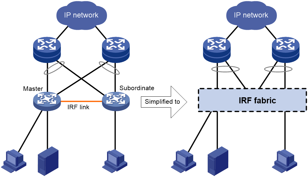
Figure 1 shows an IRF fabric that has two devices, which appear as a single node to the upper-layer and lower-layer devices.
Figure 1 IRF application scenario
IRF benefits
IRF provides the following benefits:
· Simplified topology and easy management—An IRF fabric appears as one node and is accessible at a single IP address on the network. You can use this IP address to log in at any member device to manage all the members of the IRF fabric. In addition, you do not need to run the spanning tree feature among the IRF members.
· 1:N redundancy—In an IRF fabric, one member acts as the master to manage and control the entire IRF fabric. All the other members process services while backing up the master. When the master fails, all the other member devices elect a new master from among them to take over without interrupting services.
· IRF link aggregation—You can assign several physical links between neighboring members to their IRF ports to create a load-balanced aggregate IRF connection with redundancy.
· Multichassis link aggregation—You can use the Ethernet link aggregation feature to aggregate the physical links between the IRF fabric and its upstream or downstream devices across the IRF members.
· Network scalability and resiliency—Processing capacity of an IRF fabric equals the total processing capacities of all the members. You can increase ports, network bandwidth, and processing capacity of an IRF fabric simply by adding member devices without changing the network topology.
Basic concepts
IRF member roles
IRF uses two member roles: master and standby (called subordinate throughout the documentation).
When devices form an IRF fabric, they elect a master to manage and control the IRF fabric, and all the other devices back up the master. When the master device fails, the other devices automatically elect a new master. For more information about master election, see "Master election."
IRF member ID
An IRF fabric uses member IDs to uniquely identify and manage its members. This member ID information is included as the first part of interface numbers and file paths to uniquely identify interfaces and files in an IRF fabric. Two devices cannot form an IRF fabric if they use the same member ID. A device cannot join an IRF fabric if its member ID has been used in the fabric.
Member priority
Member priority determines the possibility of a member device to be elected the master. A member with higher priority is more likely to be elected the master.
IRF port
An IRF port is a logical interface that connects IRF member devices. Every IRF-capable device has two IRF ports.
The IRF ports are named IRF-port n/1 and IRF-port n/2, where n is the member ID of the device. The two IRF ports are referred to as IRF-port 1 and IRF-port 2.
To use an IRF port, you must bind a minimum of one physical interface to it. The physical interfaces assigned to an IRF port automatically form an aggregate IRF link. An IRF port goes down when all its IRF physical interfaces are down.
IRF physical interface
IRF physical interfaces connect IRF member devices and must be bound to an IRF port. They forward traffic between member devices, including IRF protocol packets and data packets that must travel across IRF member devices.
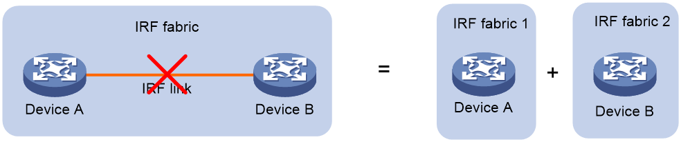
IRF split
IRF split occurs when an IRF fabric breaks up into multiple IRF fabrics because of IRF link failures, as shown in Figure 2. The split IRF fabrics operate with the same IP address. IRF split causes routing and forwarding problems on the network. To quickly detect a multi-active collision, configure a minimum of one MAD mechanism (see "Configuring MAD").
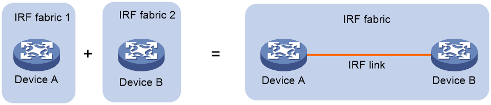
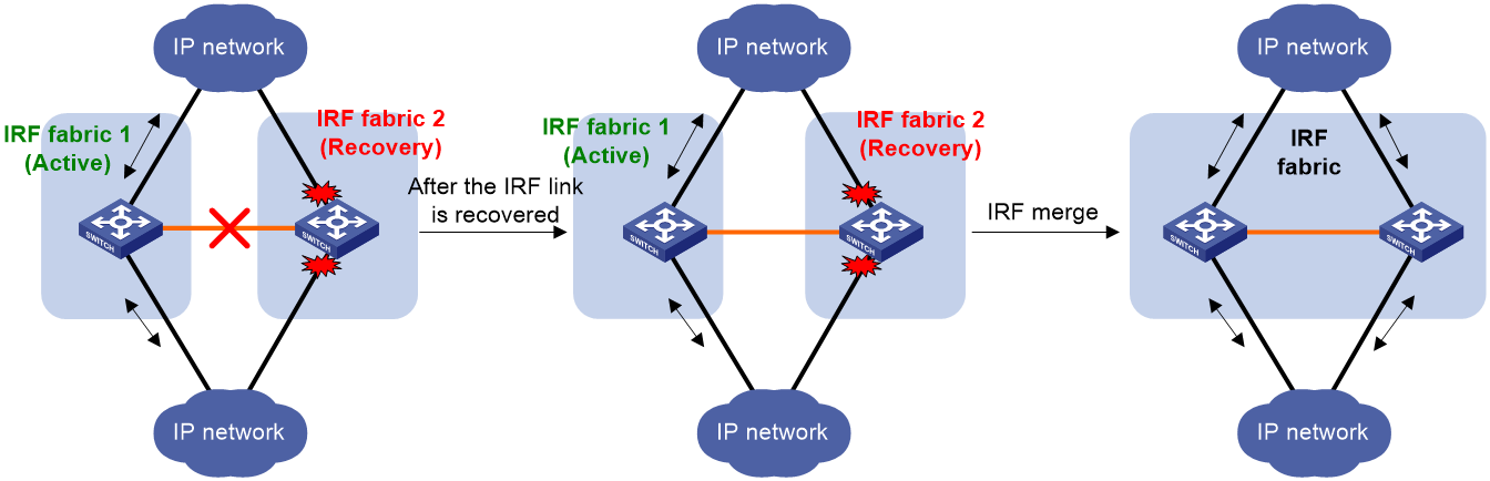
IRF merge
IRF merge occurs when two split IRF fabrics reunite or when two independent IRF fabrics are united, as shown in Figure 3.
MAD
An IRF link failure causes an IRF fabric to split in two IRF fabrics operating with the same Layer 3 settings, including the same IP address. To avoid IP address collision and network problems, IRF uses multi-active detection (MAD) mechanisms to detect the presence of multiple identical IRF fabrics, handle collisions, and recover from faults.
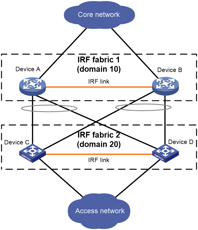
IRF domain ID
One IRF fabric forms one IRF domain. IRF uses IRF domain IDs to uniquely identify IRF fabrics and prevent IRF fabrics from interfering with one another.
As shown in Figure 4, IRF fabric 1 contains Device A and Device B, and IRF fabric 2 contains Device C and Device D. Both fabrics use the LACP aggregate links between them for MAD. When a member device receives an extended LACPDU for MAD, it checks the domain ID to determine whether the packet is from the local IRF fabric. Then, the member device can handle the packet correctly.
Figure 4 A network that contains two IRF domains
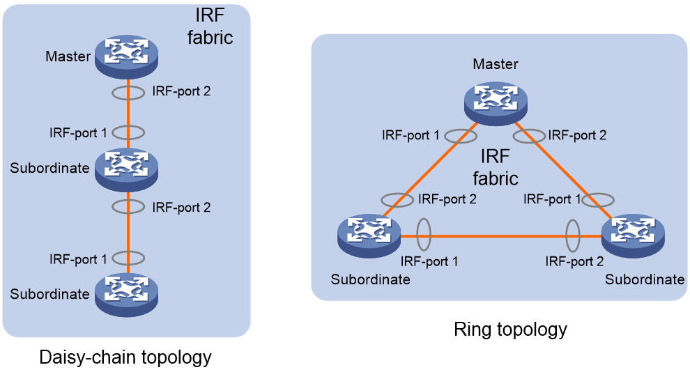
IRF network topology
An IRF fabric can use a daisy-chain or ring topology. As shown in Figure 5, a ring topology is more reliable. In ring topology, the failure of one IRF link does not cause the IRF fabric to split as in daisy-chain topology. Rather, the IRF fabric changes to a daisy-chain topology without interrupting network services.
Figure 5 Daisy-chain topology vs. ring topology
Master election
Master election occurs each time the IRF fabric topology changes in the following situations:
· The IRF fabric is established.
· The master device fails or is removed.
· The IRF fabric splits.
· Independent IRF fabrics merge.
|
|
NOTE: Master election does not occur when split IRF fabrics merge. For information about the master device of the merged IRF fabric, see "Failure recovery." |
Master election selects a master in descending order:
1. Current master, even if a new member has higher priority.
When an IRF fabric is being formed, all members consider themselves as the master. This rule is skipped.
2. Member with higher priority.
3. Member with the longest system uptime.
Two members are considered to start up at the same time if the difference between their startup times is equal to or less than 10 minutes. For these members, the next tiebreaker applies.
4. Member with the lowest CPU MAC address.
For the setup of a new IRF fabric, the subordinate devices must reboot to complete the setup after the master election.
For an IRF merge, devices must reboot if they are in the IRF fabric that fails the master election.
|
|
NOTE: When an IRF fabric reboots, its member devices might not all finish startup at the same time because of heterogeneity in device model or in expansion interface card number or model. If the member device that first finishes startup does not detect any member device within the IRF configuration detect time, the member device becomes the master regardless of its priority. Other member devices become the subordinate devices to join the IRF fabric. |
Interface naming conventions
A physical interface is numbered in the chassis-number/slot-number/interface-index format.
· chassis-number—Member ID of the device. The default value for this argument is 1. Any change to the member ID takes effect after a reboot.
· slot-number—Slot number of an interface module or the device panel. The slot number of the device panel is fixed at 0. To identity the slot number of an interface module, examine its slot number mark on the front panel.
· interface-index—Interface index on the device. Interface index depends on the number of physical interfaces available on the device. To identify the index of a physical interface, examine its index mark on the chassis.
For example, Ten-GigabitEthernet 3/0/1 represents the first fixed physical interface on member device 3. Set its link type to trunk, as follows:
<Sysname> system-view
[Sysname] interface ten-gigabitethernet 3/0/1
[Sysname-Ten-GigabitEthernet3/0/1] port link-type trunk
File system naming conventions
On a single-chassis fabric, you can use its storage device name to access its file system.
On a multichassis IRF fabric, you can use the storage device name to access the file system of the master. To access the file system of any other member device, use the name in the slotmember-ID#storage-device-name format.
For more information about storage device naming conventions, see Fundamentals Configuration Guide.
For example:
· To create and access the test folder under the root directory of the flash memory on the master switch:
<Master> mkdir test
Creating directory flash:/test... Done.
<Master> cd test
<Master> dir
Directory of flash:/test
The directory is empty.
1048576 KB total (249760 KB free)
· To create and access the test folder under the root directory of the flash memory on member device 3:
<Master> mkdir slot3#flash:/test
Creating directory slot3#flash:/test... Done.
<Master> cd slot3#flash:/test
<Master> dir
Directory of slot3#flash:/test
The directory is empty.
1048576 KB total (249760 KB free)
Configuration synchronization
IRF uses a strict running-configuration synchronization mechanism. In an IRF fabric, all devices obtain and run the running configuration of the master. Configuration changes are automatically propagated from the master to the remaining devices. The configuration files of these devices are retained, but the files do not take effect. The devices use their own startup configuration files only after they are removed from the IRF fabric.
As a best practice, back up the next-startup configuration file on a device before adding the device to an IRF fabric as a subordinate.
A subordinate device's next-startup configuration file might be overwritten if the master and the subordinate use the same file name for their next-startup configuration files. You can use the backup file to restore the original configuration after removing the subordinate from the IRF fabric.
For more information about configuration management, see Fundamentals Configuration Guide.
Multi-active handling procedure
The multi-active handling procedure includes detection, collision handling, and failure recovery.
Detection
IRF provides MAD mechanisms by extending LACP, BFD, ARP, and IPv6 ND to detect multi-active collisions. As a best practice, configure a minimum of one MAD mechanism on an IRF fabric. For more information about the MAD mechanisms and their application scenarios, see "MAD mechanisms."
For information about LACP, see Ethernet link aggregation in Layer 2—LAN Switching Configuration Guide. For information about BFD, see High Availability Configuration Guide. For information about ARP, see Layer 3—IP Services Configuration Guide. For information about ND, see IPv6 basics in Layer 3—IP Services Configuration Guide.
Collision handling
When detecting a multi-active collision, MAD disables all IRF fabrics except one from forwarding data traffic by placing them in Recovery state. The IRF fabrics placed in Recovery state are called inactive IRF fabrics. The IRF fabric that continues to forward traffic is called the active IRF fabric.
LACP MAD and BFD MAD use the following process to handle a multi-active collision:
1. Compare the health states (chip forwarding performance states) of split fabrics.
2. Set all fabrics to the Recovery state except the healthiest one.
3. Compare the number of members in each fabric if all IRF fabrics are in the same health state.
4. Set all fabrics to the Recovery state except the one that has the most members.
5. Compare the member IDs of their masters if all IRF fabrics have the same number of members.
6. Set all fabrics to the Recovery state except the one that has the lowest numbered master.
7. Shuts down all common network interfaces in the Recovery-state fabrics except for the following interfaces:
¡ Interfaces automatically excluded from being shut down by the system.
¡ Interfaces specified by using the mad exclude interface command.
ARP MAD and ND MAD use the following process to handle a multi-active collision:
1. Compare the health states (chip forwarding performance states) of split fabrics.
2. Set all fabrics to the Recovery state except the healthiest one.
3. Compare the member IDs of the masters if all IRF fabrics have the same health state.
4. Set all fabrics to the Recovery state except the one that has the lowest numbered master.
5. Take the same action as LACP MAD and BFD MAD on the network interfaces in Recovery-state fabrics.
Failure recovery
To merge two split IRF fabrics, first repair the failed IRF link and remove the IRF link failure.
When the failed IRF link between two split IRF fabrics is recovered, all member devices in the inactive IRF fabric automatically reboot to join the active IRF fabric as subordinate members. The network interfaces that have been shut down by MAD automatically restore their original state, as shown in Figure 6.
Figure 6 Recovering the IRF fabric
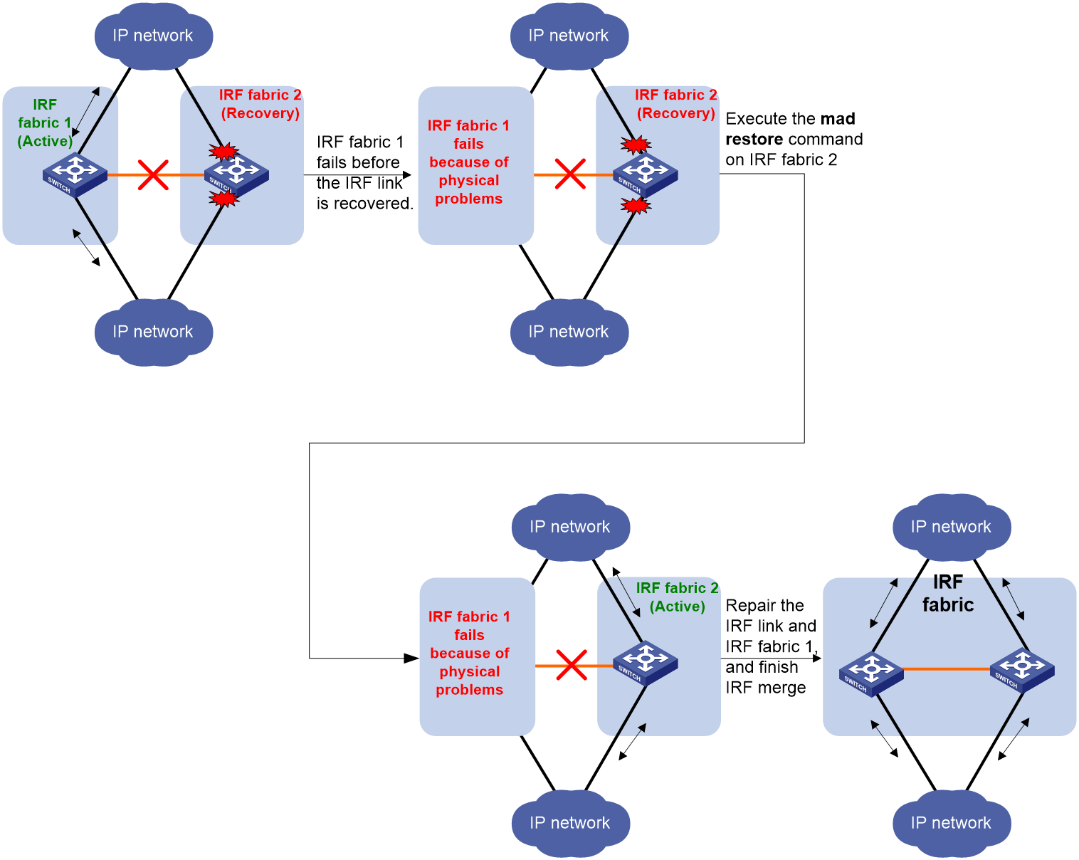
If the active IRF fabric fails before the IRF link is recovered (see Figure 7), use the mad restore command on the inactive IRF fabric to recover the inactive IRF fabric. This command brings up all network interfaces that were shut down by MAD. After the IRF link is repaired, merge the two parts into a unified IRF fabric.
Figure 7 Active IRF fabric fails before the IRF link is recovered
MAD mechanisms
IRF provides MAD mechanisms by extending LACP, BFD, ARP, and IPv6 ND.
Table 1 compares the MAD mechanisms and their application scenarios.
Table 1 Comparison of MAD mechanisms
|
MAD mechanism |
Advantages |
Disadvantages |
Application scenarios |
|
· Detection speed is fast. · Runs on existing aggregate links without requiring MAD-dedicated physical links or Layer 3 interfaces. |
Requires an intermediate device that supports extended LACP for MAD. |
Link aggregation is used between the IRF fabric and its upstream or downstream device. |
|
|
· Detection speed is fast. · Intermediate device, if used, can come from any vendor. |
Requires MAD dedicated physical links and Layer 3 interfaces, which cannot be used for transmitting user traffic. |
· No special requirements for network scenarios. · If no intermediate device is used, this mechanism is only suitable for IRF fabrics that have only two members that are geographically close to one another. |
|
|
· No intermediate device is required. · Intermediate device, if used, can come from any vendor. · Does not require MAD dedicated ports. |
· Detection speed is slower than BFD MAD and LACP MAD. · The spanning tree feature must be enabled if common Ethernet ports are used for ARP MAD links. |
Non-link aggregation IPv4 network scenarios. Spanning tree-enabled non-link aggregation IPv4 network scenarios if common Ethernet ports are used. |
|
|
· No intermediate device is required. · Intermediate device, if used, can come from any vendor. · Does not require MAD dedicated ports. |
· Detection speed is slower than BFD MAD and LACP MAD. · The spanning tree feature must be enabled if common Ethernet ports are used for ND MAD links. |
Non-link aggregation IPv6 network scenarios. Spanning tree-enabled non-link aggregation IPv6 network scenarios if common Ethernet ports are used. |
LACP MAD
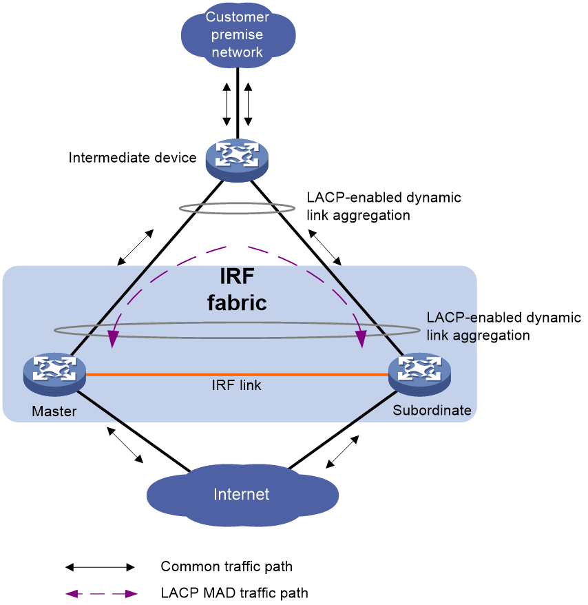
As shown in Figure 8, LACP MAD has the following requirements:
· Every IRF member must have a link with an intermediate device.
· All the links form a dynamic link aggregation group.
· The intermediate device must be a device that supports extended LACP for MAD.
The IRF member devices send extended LACPDUs that convey a domain ID and an active ID (the member ID of the master). The intermediate device transparently forwards the extended LACPDUs received from one member device to all the other member devices.
· If the domain IDs and active IDs sent by all the member devices are the same, the IRF fabric is integrated.
· If the extended LACPDUs convey the same domain ID but different active IDs, a split has occurred. LACP MAD handles this situation as described in "Collision handling."
BFD MAD
BFD MAD detects multi-active collisions by using BFD.
You can use common or management Ethernet ports for BFD MAD.
If management Ethernet ports are used, BFD MAD has the following requirements:
· An intermediate device is required and each IRF member device must have a BFD MAD link to the intermediate device.
· Each member device is assigned a MAD IP address on the master's management Ethernet port.
If common Ethernet ports are used, BFD MAD has the following requirements:
· If an intermediate device is used, each member device must have a BFD MAD link to the intermediate device. If no intermediate device is used, all member devices must have a BFD MAD link to each other.
· Ports on BFD MAD links are assigned to the same VLAN or Layer 3 aggregate interface. Each member device is assigned a MAD IP address on the VLAN interface or Layer 3 aggregate interface.
When you use BFD MAD, follow these restrictions and guidelines:
· As a best practice, use an intermediate device to connect IRF member devices if the IRF fabric has more than two member devices. A full mesh of IRF members might cause broadcast loops.
· As a best practice to avoid member device failure from affecting BFD MAD, preferentially use management Ethernet ports for BFD MAD.
· The BFD MAD links and BFD MAD VLAN (or Layer 3 aggregate interface) must be dedicated. Do not use the BFD MAD links or BFD MAD VLAN (or Layer 3 aggregate interface) for any other purposes.
· When you use a Layer 3 aggregate interface for BFD MAD, make sure its member ports do not exceed the maximum number of Selected ports allowed for an aggregation group. If the number of member ports exceeds the maximum number of Selected ports, some member ports cannot become Selected. BFD MAD will be unable to work correctly and its state will change to Faulty. For more information about setting the maximum number of Selected ports for an aggregation group, see Ethernet link aggregation in Layer 2—LAN Switching Configuration Guide.
|
|
NOTE: · The MAD addresses identify the member devices and must belong to the same subnet. · Of all management Ethernet ports on an IRF fabric, only the master's management Ethernet port is accessible. |
Figure 9 shows a typical BFD MAD scenario that uses an intermediate device. On the intermediate device, assign the ports on the BFD MAD links to the same VLAN.
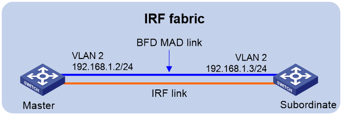
Figure 10 shows a typical BFD MAD scenario that does not use an intermediate device.
With BFD MAD, the master attempts to establish BFD sessions with other member devices by using its MAD IP address as the source IP address.
· If the IRF fabric is integrated, only the MAD IP address of the master takes effect. The master cannot establish a BFD session with any other member. If you execute the display bfd session command, the state of the BFD sessions is Down.
· When the IRF fabric splits, the IP addresses of the masters in the split IRF fabrics take effect. The masters can establish a BFD session. If you execute the display bfd session command, the state of the BFD session between the two devices is Up.
Figure 9 BFD MAD scenario with an intermediate device
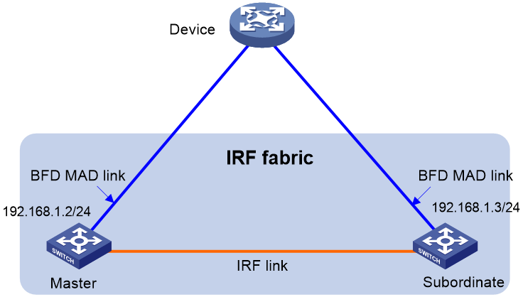
Figure 10 BFD MAD scenario without an intermediate device
ARP MAD
ARP MAD detects multi-active collisions by using extended ARP packets that convey the IRF domain ID and the active ID (the member ID of the master).
You can use common or management Ethernet ports for ARP MAD.
If management Ethernet ports are used, ARP MAD must work with an intermediate device. Make sure the following requirements are met:
· Connect a management Ethernet port on each member device to the intermediate device.
· On the intermediate device, you must assign the ports used for ARP MAD to the same VLAN.
If common Ethernet ports are used, ARP MAD can work with or without an intermediate device. Make sure the following requirements are met:
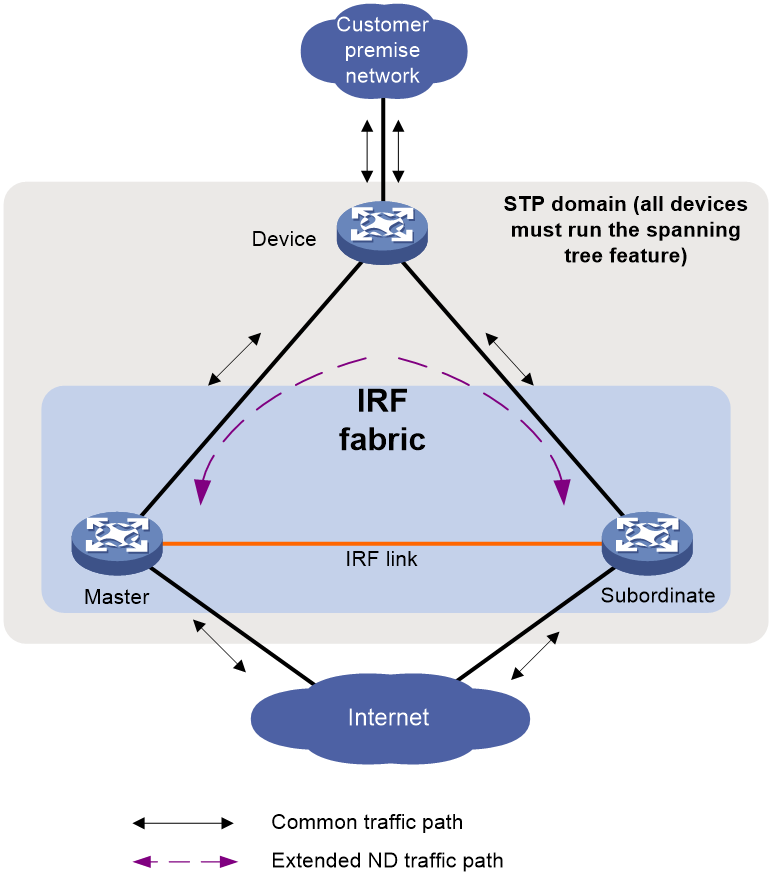
· If an intermediate device is used, connect each IRF member device to the intermediate device, as shown in Figure 11. Run the spanning tree feature between the IRF fabric and the intermediate device. In this situation, data links can be used.
· If no intermediate device is used, connect each IRF member device to all other member devices. In this situation, IRF links cannot be used for ARP MAD.
Each IRF member compares the following information in an incoming extended ARP packet with its own information to determine the integrity of the IRF fabric:
1. Compares the source IP address in the packet with its own IP address if the member device is an S6800, S6860, or S6861 switch. If the member device is not from any of these series, this step is skipped.
¡ If the IP addresses are different, the extended ARP packet is from a different IRF fabric. The device does not continue to process the packet with the MAD mechanism.
¡ If the IP addresses are the same, the device compares the domain IDs.
2. Compares the domain IDs.
¡ If the domain IDs are different, the extended ARP packet is from a different IRF fabric. The device does not continue to process the packet with the MAD mechanism.
¡ If the domain IDs are the same, the device compares the active IDs.
3. Compares the active IDs.
¡ If the active IDs are different, the IRF fabric has split.
¡ If the active IDs are the same, the IRF fabric is integrated.
Figure 11 ARP MAD scenario (common Ethernet ports)

ND MAD
ND MAD detects multi-active collisions by using NS packets to transmit the IRF domain ID and the active ID (the member ID of the master).
You can use common or management Ethernet ports for ND MAD.
If management Ethernet ports are used, ND MAD must work with an intermediate device. Make sure the following requirements are met:
· Connect a management Ethernet port on each member device to the intermediate device.
· On the intermediate device, you must assign the ports used for ND MAD to the same VLAN.
If common Ethernet ports are used, ND MAD can work with or without an intermediate device. Make sure the following requirements are met:
· If an intermediate device is used, connect each IRF member device to the intermediate device, as shown in Figure 12. Run the spanning tree feature between the IRF fabric and the intermediate device. In this situation, data links can be used.
· If no intermediate device is used, connect each IRF member device to all other member devices. In this situation, IRF links cannot be used for ND MAD.
Each IRF member device compares the domain ID and the active ID (the member ID of the master) in incoming NS packets with its domain ID and active ID.
· If the domain IDs are different, the NS packet is from a different IRF fabric. The device does not continue to process the packet with the MAD mechanism.
· If the domain IDs are the same, the device compares the active IDs.
¡ If the active IDs are different, the IRF fabric has split.
¡ If the active IDs are the same, the IRF fabric is integrated.
Figure 12 ND MAD scenario (common Ethernet ports)
Restrictions and guidelines: IRF configuration
Hardware compatibility with IRF
An S6820, S6860, or S6861 switch can form an IRF fabric only with switches from the same series.
Switches in the S6800 switch series are divided into two groups. Only S6800 switches in the same group can form an IRF fabric.
The following S6800 switches are in one group:
· The S6800-2C-FC switch.
· The S6800-54HF switch.
· The S6800-54HT switch.
· The S6800 switches with the following product codes:
¡ LS-6800-2C-H1.
¡ LS-6800-4C-H1.
¡ LS-6800-32Q-H1.
¡ LS-6800-54QF-H3.
¡ LS-6800-54QT-H3.
The S6800 switches with the following product codes are in another group:
· LS-6800-2C.
· LS-6800-4C.
· LS-6800-32Q.
Software requirements for IRF
All IRF member devices must run the same software image version. Make sure the software auto-update feature is enabled on all member devices.
Candidate IRF physical interfaces
|
|
IMPORTANT: Ports on the LSWM18CQMSEC module cannot be used as IRF physical interfaces. In a switch series that supports using QSFP+ or QSFP28 breakout interfaces to establish IRF links, some switch models and expansion interface modules might not support splitting some QSFP+ or QSFP28 ports. To identify these switch models and expansion interface modules, see the installation guide for the switch series. |
Use the following ports on the S6800 switch series for IRF links:
· 10GBase-T Ethernet ports operating at 10 Gbps.
· SFP+ ports operating at 10 Gbps.
· QSFP+ ports operating at 40 Gbps or their 10-GE breakout interfaces.
· QSFP28 ports operating at 40 Gbps or 100 Gbps.
Use the following ports on the S6820 switch series for IRF links:
· SFP28 ports operating at 25 Gbps.
· QSFP+ ports operating at 40 Gbps.
· QSFP28 ports operating at 40 Gbps or 100 Gbps, or their 25-GE breakout interfaces.
|
|
IMPORTANT: Ports on the S6820 switch series are grouped. You must follow the restrictions and guidelines described in "Grouped port binding restrictions" when you choose and configure IRF physical interfaces. |
Use the following ports on the S6860 switch series for IRF links:
· 10GBase-T Ethernet ports operating at 10 Gbps.
· SFP+ ports operating at 10 Gbps.
· QSFP+ ports operating at 40 Gbps or their 10-GE breakout interfaces.
· QSFP28 ports operating at 40 Gbps or 100 Gbps. For more information about using QSFP28 ports, see Ethernet interface configuration in Layer 2—LAN Switching Configuration Guide.
Use the following ports on the S6861 switch series for IRF links:
· 10GBase-T Ethernet ports operating at 10 Gbps.
· SFP+ ports operating at 10 Gbps.
· QSFP+ ports operating at 40 Gbps or their 10-GE breakout interfaces.
Transceiver modules and cables selection for IRF
When you select transceiver modules and cables, follow these restrictions and guidelines:
· To connect 10GBase-T Ethernet ports in a short distance, use Category 6A (or above) twisted-pair cables.
· To connect SFP+ ports in a long distance, use SFP+ transceiver modules and fibers. To connect SFP+ ports in a short distance, use SFP+ cables.
· To connect SFP28 ports in a long distance, use SFP28 transceiver modules and fibers. To connect SFP28 ports in a short distance, use SFP28 cables.
· To connect QSFP+ ports in a long distance, use QSFP+ transceiver modules and fibers. To connect QSFP+ ports in a short distance, use QSFP+ cables.
· To connect QSFP28 ports in a long distance, use QSFP28 or QSFP+ transceiver modules and fibers. To connect QSFP28 ports in a short distance, use QSFP28 or QSFP+ cables.
· The transceiver modules at the two ends of an IRF link must be the same type.
If you use ports from the highest numbered six QSFP+ ports that operate at 40 Gbps on the S6860 switch series as IRF physical interfaces, follow these restrictions and guidelines:
· If the peer ports are all from the first four QSFP+ ports or from the last two QSFP+ ports, you can use the following physical connection methods:
¡ Transceiver modules and fibers.
¡ AOC cables.
¡ DAC cables.
· To connect ports in the first four QSFP+ ports on one member to ports in the last two QSFP+ ports on another member, you must use transceiver modules and fibers or use AOC cables.
If you use a QSFP+ DAC cable to connect a pair of peer IRF physical interfaces, the peer interfaces must both be fixed ports or ports on expansion interface modules. If the peer interfaces are ports on expansion interface modules, the modules must be the same model.
For more information about the transceiver modules and cables, see the switch installation guide and H3C Transceiver Modules User Guide.
|
|
NOTE: The transceiver modules and cables available for the switch are subject to change over time. For the most up-to-date list of transceiver modules and cables, contact your H3C sales representative. |
IRF port connection
When you connect two neighboring IRF members, follow these restrictions and guidelines:
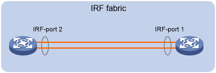
· You must connect the physical interfaces of IRF-port 1 on one member to the physical interfaces of IRF-port 2 on the other.
· For high availability, bind multiple physical interfaces to an IRF port. You can bind a maximum of eight physical interfaces to an IRF port.
Figure 13 Connecting IRF physical interfaces
IRF physical interface configuration restrictions and guidelines
Grouped port binding restrictions
The following information applies only to the S6820 switch series.
The S6820 switch series contains grouped ports, as shown in Table 2.
When you use the ports in a group for IRF links, follow these restrictions and guidelines:
· If you use one port in a group as an IRF physical interface, the remaining ports in the group can only act as IRF physical interfaces. You cannot use them for any other purposes. If you use only some of them for IRF connection, the remaining ports can only be idle.
· The ports in a group can be bound to different IRF ports.
· Before you bind one port to an IRF port, you must shut down all the ports that have not been bound to IRF ports. If any of the unbound ports are in up state, the bind action will fail.
· Before you remove one port from an IRF port, you must shut down all the ports. If any of the ports are in up state, the remove action will fail.
· Bring up the ports after you complete the bind operation. If a port is not bound to an IRF port, the system prevents you from bringing up the port so it cannot be used for purposes other than IRF connection.
|
|
NOTE: These restrictions on gouped ports do not apply if you use 100-GE ports that are not split or use 40-GE ports (except ports on the LSWM116Q module) for IRF connections. |
|
Hardware |
Port grouping rules |
|
The S6820-56HF switch |
The switch has two fixed port ranges. Ports numbered 1 to 24 are in one range and ports numbered 33 to 56 are in the other range. In each range, the ports are divided into four-port groups by port number in order, starting from the lowest number. |
|
The LSWM124TG2H module |
The ports numbered 1 to 24 are divided into four-port groups by port number in order, starting from 1. |
|
The LSWM116Q module |
Odd and even numbered ports are grouped separately into two-port groups by port number, starting from the lowest odd or even number. Each group contains two ports with consecutive odd or even port numbers. For example, ports 1 and 3 are in one group, and ports 2 and 4 are in another group. |
|
All S6820 switches |
The four 25-GE breakout interfaces of a 100-GE port are in one port group. To split a 100-GE port, use the using twenty-fivegige command. |
Command configuration restrictions
On a physical interface bound to an IRF port, you can execute only the following commands:
· Interface commands, including:
¡ description.
¡ flow-interval.
¡ shutdown.
¡ PFC commands.
For more information about these commands, see Ethernet interface configuration in Layer 2—LAN Switching Command Reference.
· MAC address table configuration commands, including the mac-address static source-check enable command. In a VXLAN or EVPN network, to ensure successful forwarding of Layer 3 traffic across member devices, use the undo mac-address static source-check enable command on each IRF physical interface. For information about this command, see Layer 2—LAN Switching Command Reference.
· LLDP commands, including:
¡ lldp admin-status.
¡ lldp check-change-interval.
¡ lldp enable.
¡ lldp encapsulation snap.
¡ lldp notification remote-change enable.
¡ lldp tlv-enable.
For more information about these commands, see Layer 2—LAN Switching Command Reference.
When you execute the port service-loopback group command on an IRF physical interface, the binding between the physical interface and the IRF port is removed. To avoid IRF split, do not assign a physical interface to a service loopback group if that interface is the only member interface of an IRF port. For information about the port service-loopback group command, see Layer 2—LAN Switching Command Reference.
When you execute the mirroring-group reflector-port command on an IRF physical interface, the binding between the physical interface and the IRF port is removed. To avoid IRF split, do not configure a physical interface as a reflector port if that interface is the only member interface of an IRF port. For information about the mirroring-group reflector-port command, see Network Management and Monitoring Command Reference.
Suppressing SNMP notifications of packet drops on IRF physical interfaces
Before an IRF member device forwards a packet, it examines its forwarding path in the IRF fabric for a loop. If a loop exists, the device discards the packet on the source interface of the looped path. This loop elimination mechanism will drop a large number of broadcast packets on the IRF physical interfaces.
To suppress SNMP notifications of packet drops that do not require attention, do not monitor packet forwarding on the IRF physical interfaces.
Feature compatibility and configuration restrictions with IRF
System operating mode
To form an IRF fabric, all member devices must work in the same system operating mode. To set the system operating mode, use the system-working-mode command. For more information about the system operating mode, see device management in Fundamentals Configuration Guide.
Hardware resource mode
To form an IRF fabric, all member devices must use the same hardware resource mode. To set the hardware resource mode, use the hardware-resource switch-mode command. For more information about hardware resource modes, see device management in Fundamentals Configuration Guide.
Routing settings
To form an IRF fabric, all member devices must use the same settings for the following routing features:
· Maximum number of ECMP routes (set by using the max-ecmp-num command).
· ECMP mode (set by using the ecmp mode command).
· Support for IPv6 routes with prefixes longer than 64 bits (set by using the hardware-resource routing-mode ipv6-128 command).
For more information about the routing features, see basic IP routing configuration in Layer 3—IP Routing Configuration Guide.
OpenFlow
To form an IRF fabric, all member devices must use the same setting for the openflow lossless enable command. This command determines the enabling status of the packet loss prevention feature for OpenFlow forwarding. For more information about this feature, see OpenFlow Configuration Guide.
VXLAN
To form an IRF fabric, all member devices must use the same VXLAN hardware resource mode. To set the VXLAN hardware resource mode, use the hardware-resource vxlan command. For more information about the VXLAN hardware resource mode, see VXLAN Configuration Guide.
Licensing requirements for IRF
For a license-based feature to run correctly on an IRF fabric, make sure the licenses installed for the feature on all member devices are the same. For more information about feature licensing, see Fundamentals Configuration Guide.
Configuration rollback restrictions
The configuration rollback feature cannot roll back the following IRF settings:
· Member device description (set by using the irf member description command).
· Member device priority (set by using the irf member priority command).
· IRF physical interface and IRF port bindings (set by using the port group interface command).
For more information about the configuration rollback feature, see configuration file management in Fundamentals Configuration Guide.
IRF tasks at a glance
To configure IRF, perform the following tasks:
Configure a minimum of one MAD mechanism on an IRF fabric. For the MAD compatibility, see "MAD mechanism compatibility."
¡ Excluding interfaces from the shutdown action upon detection of multi-active collision
This feature excludes an interface from the shutdown action for management or other special purposes when an IRF fabric transits to the Recovery state.
3. (Optional.) Optimizing IRF settings for an IRF fabric
¡ Configuring a member device description
¡ Configuring IRF link load sharing mode
¡ Configuring IRF bridge MAC address settings
¡ Enabling software auto-update for software image synchronization
This feature automatically synchronizes the current software images of the master to devices that are attempting to join the IRF fabric.
¡ Setting the IRF link down report delay
¡ Removing an interface module that has IRF physical interfaces
¡ Replacing an interface module that has IRF physical interfaces
Planning the IRF fabric setup
Consider the following items when you plan an IRF fabric:
· Hardware compatibility and restrictions.
· IRF fabric size.
· Master device.
· Member ID and priority assignment scheme.
· Fabric topology and cabling scheme.
· IRF physical interfaces.
Setting up an IRF fabric
IRF setup tasks at a glance
To set up an IRF fabric, perform the following tasks:
4. Configure member IDs, priorities, and IRF physical interfaces separately.
a. Assigning a member ID to each IRF member device
b. (Optional.) Specifying a priority for each member device
c. Binding physical interfaces to IRF ports
Skip these tasks if you configure member IDs, priorities, domain ID, and IRF physical interfaces in bulk.
5. Bulk-configuring basic IRF settings for a member device
Skip this task if you configure member IDs, priorities, domain ID, and IRF physical interfaces separately.
6. Connecting IRF physical interfaces
Assigning a member ID to each IRF member device
Restrictions and guidelines
To create an IRF fabric, you must assign a unique IRF member ID to each member device.
The new member ID of a device takes effect at a reboot. After the device reboots, the settings on all member ID-related physical resources (including common physical network interfaces) are removed, regardless of whether you have saved the configuration.
If configured with the port media-type copper command, the following ports cannot come up automatically after you change the device's member ID and reboots the device:
· Twenty-FiveGigE 1/0/1 through Twenty-FiveGigE 1/0/8 and Twenty-FiveGigE 1/0/49 through Twenty-FiveGigE 1/0/56 on the S6820-56HF switch.
· 25G ports on the LSWM124TG2H module.
To resolve this issue, you must re-execute the port media-type copper command on these IRF physical interfaces. For more information about the port media-type copper command, see Ethernet interface configuration in Layer 2—LAN Switching Configuration Guide.
In an IRF fabric, changing IRF member IDs might cause undesirable configuration changes and data loss. Before you do that, back up the configuration, and make sure you fully understand the impact on your network.
Procedure
1. Enter system view.
system-view
2. Assign a member ID to a member device.
irf member member-id renumber new-member-id
The default IRF member ID is 1.
3. (Optional.) Save the configuration.
save
If you have bound physical interfaces to IRF ports or assigned member priority, you must perform this step for these settings to take effect after the reboot.
4. Return to user view.
quit
5. Reboot the device.
reboot [ slot slot-number ] [ force ]
Specifying a priority for each member device
About specifying an IRF member priority
IRF member priority represents the possibility for a device to be elected the master in an IRF fabric. A larger priority value indicates a higher priority.
A change to member priority affects the election result at the next master election, but it does not cause an immediate master re-election.
Procedure
1. Enter system view.
system-view
2. Specify a priority for the device.
irf member member-id priority priority
The default IRF member priority is 1.
Binding physical interfaces to IRF ports
Restrictions and guidelines
Select qualified physical interfaces as IRF physical interfaces as described in "Candidate IRF physical interfaces."
When you preconfigure an interface module that already has IRF physical interfaces, do not configure any features other than IRF port bindings on the IRF physical interfaces.
After binding physical interfaces to IRF ports for the first time, you must use the irf-port-configuration active command to activate the settings on the IRF ports.
The system activates the IRF port settings automatically only in the following situations:
· The configuration file that the device starts with contains IRF port bindings.
· You are adding physical interfaces to an IRF port (in UP state) after an IRF fabric is formed.
Procedure
1. Enter system view.
system-view
2. Enter interface view or interface range view.
¡ Enter interface view.
interface interface-type interface-number
¡ Enter interface range view. Choose one of the following commands:
interface range { interface-type interface-number [ to interface-type interface-number ] } &<1-24>
interface range name name [ interface { interface-type interface-number [ to interface-type interface-number ] } &<1-24> ]
To shut down a range of IRF physical interfaces, enter interface range view.
To shut down one IRF physical interface, enter its interface view.
3. Shut down the physical interfaces.
shutdown
By default, a physical interface is up.
4. Return to system view.
quit
5. Enter IRF port view.
irf-port member-id/irf-port-number
6. Bind each physical interface to the IRF port.
port group interface interface-type interface-number
By default, no physical interfaces are bound to an IRF port.
Repeat this step to assign multiple physical interfaces to the IRF port.
7. Return to system view.
quit
8. Enter interface view or interface range view.
¡ Enter interface view.
interface interface-type interface-number
¡ Enter interface range view. Choose one of the following commands:
interface range { interface-type interface-number [ to interface-type interface-number ] } &<1-24>
interface range name name [ interface { interface-type interface-number [ to interface-type interface-number ] } &<1-24> ]
9. Bring up the physical interfaces.
undo shutdown
10. Return to system view.
quit
11. Save the configuration.
save
Activating IRF port configurations causes IRF merge and reboot. To avoid data loss, save the running configuration to the startup configuration file before you perform the operation.
12. Activate the IRF port settings.
irf-port-configuration active
Bulk-configuring basic IRF settings for a member device
About easy IRF
Use the easy IRF feature to bulk-configure basic IRF settings for a member device, including the member ID, domain ID, priority, and IRF port bindings.
The easy IRF feature provides the following configuration methods:
· Interactive method—Enter the easy-irf command without parameters. The system will guide you to set the parameters step by step.
· Non-interactive method—Enter the easy-irf command with parameters.
As a best practice, use the interactive method if you are new to IRF.
Restrictions and guidelines
The member device reboots immediately after you specify a new member ID for it. Make sure you are aware of the impact on the network.
If you execute the easy-irf command multiple times, the following settings take effect:
· The most recent settings for the member ID, domain ID, and priority.
· IRF port bindings added through repeated executions of the command. To remove an IRF physical interface from an IRF port, you must use the undo port group interface command in IRF port view.
If you specify IRF physical interfaces by using the interactive method, you must also follow these restrictions and guidelines:
· Do not enter spaces between the interface type and interface number.
· Use a comma (,) to separate two physical interfaces. No spaces are allowed between interfaces.
Procedure
1. Enter system view.
system-view
2. Bulk-configure basic IRF settings for the device.
easy-irf [ member member-id [ renumber new-member-id ] domain domain-id [ priority priority ] [ irf-port1 interface-list1 ] [ irf-port2 interface-list2 ] ]
Make sure the new member ID is unique in the IRF fabric to which the device will be added.
Connecting IRF physical interfaces
Follow the restrictions in "IRF port connection" to connect IRF physical interfaces as well as based on the topology and cabling scheme. The devices perform master election. The member devices that fail the master election automatically reboot to form an IRF fabric with the master device.
Accessing the IRF fabric
The IRF fabric appears as one device after it is formed. You configure and manage all IRF members at the CLI of the master. All settings you have made are automatically propagated to the IRF members.
The following methods are available for accessing an IRF fabric:
· Local login—Log in through the console port of any member device.
· Remote login—Log in at a Layer 3 interface on any member device by using methods including Telnet and SNMP.
When you log in to an IRF fabric, you are placed at the CLI of the master, regardless of at which member device you are logged in.
For more information, see login configuration in Fundamentals Configuration Guide.
Configuring MAD
Restrictions and guidelines for MAD configuration
MAD mechanism compatibility
As a best practice, configure a minimum of one MAD mechanism on an IRF fabric for prompt IRF split detection. Because MAD mechanisms use different collision handling processes, follow these restrictions and guidelines when you configure multiple MAD mechanisms on an IRF fabric:
· Do not configure LACP MAD together with ARP MAD or ND MAD.
· Do not configure BFD MAD together with ARP MAD or ND MAD.
Assigning IRF domain IDs
An IRF fabric has only one IRF domain ID. You can change the IRF domain ID by using the following commands: irf domain, mad enable, mad arp enable, or mad nd enable. The IRF domain IDs configured by using these commands overwrite each other.
If LACP MAD, ARP MAD, or ND MAD runs between two IRF fabrics, assign each fabric a unique IRF domain ID. (For BFD MAD, this task is optional.)
Bringing up interfaces shut down by MAD
To prevent an interface from being shut down when the IRF fabric transits to the Recovery state, use the mad exclude interface command.
To bring up the interfaces shut down by a MAD mechanism in a Recovery-state IRF fabric, use the mad restore command instead of the undo shutdown command. The mad restore command activates the Recovery-state IRF fabric.
Configuring LACP MAD
1. Enter system view.
system-view
2. Assign a domain ID to the IRF fabric.
irf domain domain-id
The default IRF domain ID is 0.
3. Create an aggregate interface and enter aggregate interface view.
¡ Enter Layer 2 aggregate interface view.
interface bridge-aggregation interface-number
¡ Enter Layer 3 aggregate interface view.
interface route-aggregation interface-number
Perform this step also on the intermediate device.
4. Configure the aggregation group to operate in dynamic aggregation mode.
link-aggregation mode dynamic
By default, an aggregation group operates in static aggregation mode.
LACP MAD takes effect only on dynamic aggregate interfaces.
Perform this step also on the intermediate device.
5. Enable LACP MAD.
mad enable
By default, LACP MAD is disabled.
6. Return to system view.
quit
7. Enter Ethernet interface view or interface range view.
¡ Enter Ethernet interface view.
interface interface-type interface-number
¡ Enter interface range view. Choose one of the following commands:
interface range { interface-type interface-number [ to interface-type interface-number ] } &<1-24>
interface range name name [ interface { interface-type interface-number [ to interface-type interface-number ] } &<1-24> ]
To assign a range of ports to the aggregation group, enter interface range view.
To assign one port to the aggregation group, enter Ethernet interface view.
8. Assign the Ethernet port or the range of Ethernet ports to the specified aggregation group.
port link-aggregation group group-id
Multichassis link aggregation is allowed.
Perform this step also on the intermediate device.
Configuring BFD MAD
Restrictions and guidelines for configuring BFD MAD
As a best practice, use the following procedure to set up BFD MAD:
1. Choose a BFD MAD link scheme as described in "BFD MAD."
2. Configure BFD MAD.
3. Connect the BFD MAD links.
When you configure BFD MAD on a VLAN interface, follow these restrictions and guidelines:
|
Category |
Restrictions and guidelines |
|
BFD MAD VLAN |
· Do not enable BFD MAD on VLAN-interface 1. · If you are using an intermediate device, perform the following tasks: ¡ On the IRF fabric and the intermediate device, create a VLAN for BFD MAD. ¡ On the IRF fabric and the intermediate device, assign the ports of BFD MAD links to the BFD MAD VLAN. ¡ On the IRF fabric, create a VLAN interface for the BFD MAD VLAN. · Make sure the IRF fabrics on the network use different BFD MAD VLANs. · Make sure the BFD MAD VLAN contains only ports on the BFD MAD links. Exclude a port from the BFD MAD VLAN if that port is not on a BFD MAD link. If you have assigned that port to all VLANs by using the port trunk permit vlan all command, use the undo port trunk permit command to exclude that port from the BFD MAD VLAN. |
|
BFD MAD VLAN and feature compatibility |
Do not use the BFD MAD VLAN and its member ports for any purpose other than configuring BFD MAD. · Use only the mad bfd enable and mad ip address commands on the BFD MAD-enabled VLAN interface. If you configure other features, both BFD MAD and other features on the interface might run incorrectly. · Disable the spanning tree feature on any Layer 2 Ethernet ports in the BFD MAD VLAN. The MAD feature is mutually exclusive with the spanning tree feature. |
|
MAD IP address |
· To avoid network issues, only use the mad ip address command to configure IP addresses on the BFD MAD-enabled VLAN interface. Do not configure an IP address by using the ip address command or configure a VRRP virtual address on the BFD MAD-enabled VLAN interface. · Make sure all the MAD IP addresses are on the same subnet. |
When you configure BFD MAD on a Layer 3 aggregate interface, follow these restrictions and guidelines:
|
Category |
Restrictions and guidelines |
|
BFD MAD-enabled Layer 3 aggregate interface |
· Make sure the Layer 3 aggregate interface operates in static aggregation mode. · Make sure the member ports in the aggregation group do not exceed the maximum number of Selected ports allowed for an aggregation group. If the number of member ports exceeds the maximum number of Selected ports, some member ports cannot become Selected. BFD MAD will be unable to work correctly and its state will change to Faulty. |
|
BFD MAD VLAN |
· On the intermediate device (if any), assign the ports on the BFD MAD links to the same VLAN. Do not assign the ports to an aggregate interface. If the ports are hybrid ports, make sure these ports are untagged members of their PVIDs. · If the intermediate device acts as a BFD MAD intermediate device for multiple IRF fabrics, assign different BFD MAD VLANs to the IRF fabrics. · Do not use the BFD MAD VLAN on the intermediate device for any purposes other than BFD MAD. · Make sure the BFD MAD VLAN on the intermediate device contains only ports on the BFD MAD links. Exclude a port from the BFD MAD VLAN if that port is not on a BFD MAD link. If you have assigned that port to all VLANs by using the port trunk permit vlan all command, use the undo port trunk permit command to exclude that port from the BFD MAD VLAN. |
|
BFD MAD-enabled Layer 3 aggregate interface and feature compatibility |
Use only the mad bfd enable and mad ip address commands on the BFD MAD-enabled interface. If you configure other features, both BFD MAD and other features on the interface might run incorrectly. |
|
MAD IP address |
· To avoid network issues, only use the mad ip address command to configure IP addresses on the BFD MAD-enabled interface. Do not configure an IP address by using the ip address command or configure a VRRP virtual address on the BFD MAD-enabled interface. · Make sure all the MAD IP addresses are on the same subnet. |
When you configure BFD MAD on a management Ethernet port, follow these restrictions and guidelines:
|
Category |
Restrictions and guidelines |
|
Management Ethernet ports for BFD MAD |
Connect a management Ethernet port on each IRF member device to the common Ethernet ports on the intermediate device. |
|
BFD MAD VLAN |
· On the intermediate device, create a VLAN for BFD MAD, and assign the ports used for BFD MAD to the VLAN. On the IRF fabric, you do not need to assign the management Ethernet ports to the VLAN. · Make sure the IRF fabrics on the network use different BFD MAD VLANs. · Make sure the BFD MAD VLAN on the intermediate device contains only ports on the BFD MAD links. |
|
MAD IP address |
· Use the mad ip address command instead of the ip address command to configure MAD IP addresses on the BFD MAD-enabled management Ethernet ports. · Make sure all the MAD IP addresses are on the same subnet. |
Configuring BFD MAD on a VLAN interface
1. Enter system view.
system-view
2. (Optional.) Assign a domain ID to the IRF fabric.
irf domain domain-id
By default, the domain ID of an IRF fabric is 0.
3. Create a VLAN dedicated to BFD MAD.
vlan vlan-id
By default, only VLAN 1 exists.
Do not enable BFD MAD on VLAN-interface 1.
Perform this step also on the intermediate device (if any).
4. Return to system view.
quit
5. Enter Ethernet interface view or interface range view.
¡ Enter Ethernet interface view.
interface interface-type interface-number
¡ Enter interface range view. Choose one of the following commands:
interface range { interface-type interface-number [ to interface-type interface-number ] } &<1-24>
interface range name name [ interface { interface-type interface-number [ to interface-type interface-number ] } &<1-24> ]
To assign a range of ports to the BFD MAD VLAN, enter interface range view.
To assign one port to the BFD MAD VLAN, enter Ethernet interface view.
6. Assign the port or the range of ports to the BFD MAD VLAN.
¡ Assign the ports to the VLAN as access ports.
port access vlan vlan-id
¡ Assign the ports to the VLAN as trunk ports.
port trunk permit vlan vlan-id
¡ Assign the ports to the VLAN as hybrid ports.
port hybrid vlan vlan-id { tagged | untagged }
The link type of BFD MAD ports can be access, trunk, or hybrid.
The default link type of a port is access.
Perform this step also on the intermediate device (if any).
7. Return to system view.
quit
8. Enter VLAN interface view.
interface vlan-interface vlan-interface-id
9. Enable BFD MAD.
mad bfd enable
By default, BFD MAD is disabled.
10. Assign a MAD IP address to a member device on the VLAN interface.
mad ip address ip-address { mask | mask-length } member member-id
By default, no MAD IP addresses are configured on any VLAN interfaces.
Repeat this step to assign a MAD IP address to each member device on the VLAN interface.
Configuring BFD MAD on a Layer 3 aggregate interface
1. Enter system view.
system-view
2. (Optional.) Assign a domain ID to the IRF fabric.
irf domain domain-id
By default, the domain ID of an IRF fabric is 0.
3. Create a Layer 3 aggregate interface for BFD MAD.
interface route-aggregation interface-number
4. Return to system view.
quit
5. Enter interface view or interface range view.
¡ Enter Ethernet interface view.
interface interface-type interface-number
¡ Enter interface range view. Choose one of the following commands:
interface range { interface-type interface-number [ to interface-type interface-number ] } &<1-24>
interface range name name [ interface { interface-type interface-number [ to interface-type interface-number ] } &<1-24> ]
To assign a range of ports to the aggregation group for the aggregate interface, enter interface range view.
To assign one port to the aggregation group for the aggregate interface, enter Ethernet interface view.
6. Assign the port or the range of ports to the aggregation group for the aggregate interface.
port link-aggregation group number
7. Return to system view.
quit
8. Enter Layer 3 aggregate interface view.
interface route-aggregation interface-number
9. Enable BFD MAD.
mad bfd enable
By default, BFD MAD is disabled.
10. Assign a MAD IP address to a member device on the Layer 3 aggregate interface.
mad ip address ip-address { mask | mask-length } member member-id
By default, no MAD IP addresses are configured on aggregate interfaces.
Repeat this step to assign a MAD IP address to each member device on the aggregate interface.
Configuring BFD MAD on a management Ethernet port
1. Enter system view.
system-view
2. (Optional.) Assign a domain ID to the IRF fabric.
irf domain domain-id
By default, the domain ID of an IRF fabric is 0.
3. Enter management Ethernet interface view.
interface m-gigabitethernet interface-number
Of all management Ethernet ports on an IRF fabric, only the master's management Ethernet port is accessible.
4. Enable BFD MAD.
mad bfd enable
By default, BFD MAD is disabled.
5. Assign a MAD IP address to each member device.
mad ip address ip-address { mask | mask-length } member member-id
By default, no MAD IP addresses are configured.
Configuring ARP MAD
Restrictions and guidelines for configuring ARP MAD
As a best practice, use the following procedure to set up ARP MAD:
1. Choose an ARP MAD link scheme as described in "ARP MAD."
2. Configure ARP MAD.
3. Connect the ARP MAD links if you are not using existing data links as ARP MAD links.
When you configure ARP MAD on a VLAN interface, follow these restrictions and guidelines:
|
Category |
Restrictions and guidelines |
|
ARP MAD VLAN |
· Do not enable ARP MAD on VLAN-interface 1. · If you are using an intermediate device, perform the following tasks: ¡ On the IRF fabric and the intermediate device, create a VLAN for ARP MAD. ¡ On the IRF fabric and the intermediate device, assign the ports of ARP MAD links to the ARP MAD VLAN. ¡ On the IRF fabric, create a VLAN interface for the ARP MAD VLAN. · Do not use the ARP MAD VLAN for any other purposes. |
|
ARP MAD and feature configuration |
If an intermediate device is used, make sure the following requirements are met: · Run the spanning tree feature between the IRF fabric and the intermediate device to ensure that there is only one ARP MAD link in forwarding state. For more information about the spanning tree feature and its configuration, see Layer 2—LAN Switching Configuration Guide. · Enable the IRF fabric to change its bridge MAC address as soon as the address owner leaves. · If the intermediate device is also an IRF fabric, assign the two IRF fabrics different domain IDs for correct split detection. |
When you configure ARP MAD on a management Ethernet port, follow these restrictions and guidelines:
|
Category |
Restrictions and guidelines |
|
Management Ethernet ports for ARP MAD |
Connect a management Ethernet port on each member device to the common Ethernet ports on the intermediate device. |
|
ARP MAD VLAN |
On the intermediate device, create a VLAN for ARP MAD, and assign the ports used for ARP MAD to the VLAN. On the IRF fabric, you do not need to assign the management Ethernet ports to the VLAN. |
|
ARP MAD and feature configuration |
· Enable the IRF fabric to change its bridge MAC address as soon as the address owner leaves. · If the intermediate device is also an IRF fabric, assign the two IRF fabrics different domain IDs for correct split detection. |
Configuring ARP MAD on a VLAN interface
1. Enter system view.
system-view
2. Assign a domain ID to the IRF fabric.
irf domain domain-id
The default IRF domain ID is 0.
3. Configure the IRF bridge MAC address to change as soon as the address owner leaves.
undo irf mac-address persistent
By default, the IRF bridge MAC address remains unchanged for 12 minutes after the address owner leaves.
4. Create a VLAN dedicated to ARP MAD.
vlan vlan-id
By default, only VLAN 1 exists.
Do not configure ARP MAD on VLAN-interface 1.
Perform this task also on the intermediate device (if any).
5. Return to system view.
quit
6. Enter Ethernet interface view or interface range view.
¡ Enter Ethernet interface view.
interface interface-type interface-number
¡ Enter interface range view. Choose one of the following commands:
interface range { interface-type interface-number [ to interface-type interface-number ] } &<1-24>
interface range name name [ interface { interface-type interface-number [ to interface-type interface-number ] } &<1-24> ]
To assign a range of ports to the ARP MAD VLAN, enter interface range view.
To assign one port to the ARP MAD VLAN, enter Ethernet interface view.
7. Assign the port or the range of ports to the ARP MAD VLAN.
¡ Assign the ports to the VLAN as access ports.
port access vlan vlan-id
¡ Assign the ports to the VLAN as trunk ports.
port trunk permit vlan vlan-id
¡ Assign the ports to the VLAN as hybrid ports.
port hybrid vlan vlan-id { tagged | untagged }
The link type of ARP MAD ports can be access, trunk, or hybrid.
The default link type of a port is access.
Perform this task also on the intermediate device (if any).
8. Return to system view.
quit
9. Enter VLAN interface view.
interface vlan-interface vlan-interface-id
10. Assign the interface an IP address.
ip address ip-address { mask | mask-length }
By default, no IP addresses are assigned to any VLAN interfaces.
11. Enable ARP MAD.
mad arp enable
By default, ARP MAD is disabled.
Configuring ARP MAD on a management Ethernet port
1. Enter system view.
system-view
2. Assign a domain ID to the IRF fabric.
irf domain domain-id
The default IRF domain ID is 0.
3. Configure the IRF bridge MAC address to change as soon as the address owner leaves.
undo irf mac-address persistent
By default, the IRF bridge MAC address remains unchanged for 12 minutes after the address owner leaves.
4. Enter management Ethernet interface view.
interface m-gigabitethernet interface-number
Of all management Ethernet ports on an IRF fabric, only the master's management Ethernet port is accessible.
5. Assign an IP address to the management Ethernet port.
ip address ip-address { mask | mask-length }
By default, no IP addresses are configured.
6. Enable ARP MAD.
mad arp enable
By default, ARP MAD is disabled.
Configuring ND MAD
Restrictions and guidelines for configuring ND MAD
As a best practice, use the following procedure to set up ND MAD:
1. Choose an ND MAD link scheme as described in "ND MAD."
2. Configure ND MAD.
3. Connect the ND MAD links if you are not using existing data links as ND MAD links.
When you configure ND MAD on a VLAN interface, follow these restrictions and guidelines:
|
Category |
Restrictions and guidelines |
|
ND MAD VLAN |
· Do not enable ND MAD on VLAN-interface 1. · If you are using an intermediate device, perform the following tasks: ¡ On the IRF fabric and the intermediate device, create a VLAN for ND MAD. ¡ On the IRF fabric and the intermediate device, assign the ports of ND MAD links to the ND MAD VLAN. ¡ On the IRF fabric, create a VLAN interface for the ND MAD VLAN. · Do not use the ND MAD VLAN for any other purposes. |
|
ND MAD and feature configuration |
If an intermediate device is used, make sure the following requirements are met: · Run the spanning tree feature between the IRF fabric and the intermediate device to ensure that there is only one ND MAD link in forwarding state. For more information about the spanning tree feature and its configuration, see Layer 2—LAN Switching Configuration Guide. · Enable the IRF fabric to change its bridge MAC address as soon as the address owner leaves. · If the intermediate device is also an IRF fabric, assign the two IRF fabrics different domain IDs for correct split detection. |
When you configure ND MAD on a management Ethernet port, follow these restrictions and guidelines:
|
Category |
Restrictions and guidelines |
|
Management Ethernet ports for ND MAD |
Connect a management Ethernet port on each member device to the common Ethernet ports on the intermediate device. |
|
ND MAD VLAN |
On the intermediate device, create a VLAN for ND MAD, and assign the ports used for ND MAD to the VLAN. On the IRF fabric, you do not need to assign the management Ethernet ports to the VLAN. |
|
ND MAD and feature configuration |
· Enable the IRF fabric to change its bridge MAC address as soon as the address owner leaves. · If the intermediate device is also an IRF fabric, assign the two IRF fabrics different domain IDs for correct split detection. |
Configuring ND MAD on a VLAN interface
1. Enter system view.
system-view
2. Assign a domain ID to the IRF fabric.
irf domain domain-id
The default IRF domain ID is 0.
3. Configure the IRF bridge MAC address to change as soon as the address owner leaves.
undo irf mac-address persistent
By default, the IRF bridge MAC address remains unchanged for 12 minutes after the address owner leaves the fabric.
4. Create a VLAN dedicated to ND MAD.
vlan vlan-id
By default, only VLAN 1 exists.
Do not configure ND MAD on VLAN-interface 1.
Perform this task also on the intermediate device (if any).
5. Return to system view.
quit
6. Enter Ethernet interface view or interface range view.
¡ Enter Ethernet interface view.
interface interface-type interface-number
¡ Enter interface range view. Choose one of the following commands:
interface range { interface-type interface-number [ to interface-type interface-number ] } &<1-24>
interface range name name [ interface { interface-type interface-number [ to interface-type interface-number ] } &<1-24> ]
To assign a range of ports to the ND MAD VLAN, enter interface range view.
To assign one port to the ND MAD VLAN, enter Ethernet interface view.
7. Assign the port or the range of ports to the ND MAD VLAN.
¡ Assign the ports to the VLAN as access ports.
port access vlan vlan-id
¡ Assign the ports to the VLAN as trunk ports.
port trunk permit vlan vlan-id
¡ Assign the ports to the VLAN as hybrid ports.
port hybrid vlan vlan-id { tagged | untagged }
The link type of ND MAD ports can be access, trunk, or hybrid.
The default link type of a port is access.
Perform this task also on the intermediate device (if any).
8. Return to system view.
quit
9. Enter VLAN interface view.
interface vlan-interface interface-number
10. Assign the interface an IPv6 address.
ipv6 address { ipv6-address/prefix-length | ipv6-address prefix-length }
By default, no IPv6 addresses are assigned to a VLAN interface.
11. Enable ND MAD.
mad nd enable
By default, ND MAD is disabled.
Configuring ND MAD on a management Ethernet port
1. Enter system view.
system-view
2. Assign a domain ID to the IRF fabric.
irf domain domain-id
The default IRF domain ID is 0.
3. Configure the IRF bridge MAC address to change as soon as the address owner leaves.
undo irf mac-address persistent
By default, the IRF bridge MAC address remains unchanged for 12 minutes after the address owner leaves the fabric.
4. Enter management Ethernet interface view.
interface m-gigabitethernet interface-number
Of all management Ethernet ports on an IRF fabric, only the master's management Ethernet port is accessible.
5. Assign an IPv6 address to the management Ethernet port.
ipv6 address { ipv6-address/pre-length | ipv6 address pre-length }
By default, no IPv6 addresses are assigned to a management Ethernet port.
6. Enable ND MAD.
mad nd enable
By default, ND MAD is disabled.
Excluding interfaces from the shutdown action upon detection of multi-active collision
About excluding interfaces from being shut down
When an IRF fabric transits to the Recovery state, the system automatically excludes the following network interfaces from being shut down:
· IRF physical interfaces.
· Interfaces used for BFD MAD.
· Member interfaces of an aggregate interface if the aggregate interface is excluded from being shut down.
You can exclude an interface from the shutdown action for management or other special purposes. For example:
· Exclude a port from the shutdown action so you can Telnet to the port for managing the device.
· Exclude a VLAN interface and its Layer 2 ports from the shutdown action so you can log in through the VLAN interface.
Restrictions and guidelines
If the Layer 2 ports of a VLAN interface are distributed on multiple member devices, the exclusion operation might introduce IP collision risks. The VLAN interface might be up on both active and inactive IRF fabrics.
Procedure
1. Enter system view.
system-view
2. Configure an interface to not shut down when the IRF fabric transits to the Recovery state.
mad exclude interface interface-type interface-number
By default, all network interfaces on a Recovery-state IRF fabric are shut down, except for the network interfaces automatically excluded by the system.
Recovering an IRF fabric
About recovering an IRF fabric
If the active IRF fabric fails before the IRF link is recovered, perform this task on the inactive IRF fabric to recover the inactive IRF fabric for traffic forwarding. The manual recovery operation brings up all interfaces that were shut down by MAD on the inactive IRF fabric.
Procedure
1. Enter system view.
system-view
2. Recover the inactive IRF fabric.
mad restore
Optimizing IRF settings for an IRF fabric
Configuring a member device description
1. Enter system view.
system-view
2. Configure a description for a member device.
irf member member-id description text
By default, no member device description is configured.
Configuring IRF link load sharing mode
About IRF link load sharing mode
On an IRF port, traffic is balanced across its physical links.
You can configure the IRF port to distribute traffic based on any combination of the following criteria:
· IP addresses.
· MAC addresses.
The system displays an error message if a criteria combination is not supported.
The criteria can also be packet types, such as Layer 2, IPv4, and IPv6.
Restrictions and guidelines for configuring IRF link load sharing mode
Configure the IRF link load sharing mode for IRF links in system view or IRF port view:
· In system view, the configuration is global and takes effect on all IRF ports.
· In IRF port view, the configuration is port specific and takes effect only on the specified IRF port.
An IRF port preferentially uses the port-specific load sharing mode. If no port-specific load sharing mode is available, the IRF port uses the global load sharing mode.
Before you configure a port-specific load sharing mode, make sure you have bound a minimum of one physical interface to the IRF port.
Configuring the global load sharing mode
1. Enter system view.
system-view
2. Configure the global IRF link load sharing mode.
irf-port global load-sharing mode { destination-ip | destination-mac | source-ip | source-mac } *
By default, packets are distributed automatically across IRF member links based on packet types.
If you execute this command multiple times, the most recent configuration takes effect.
Configuring a port-specific load sharing mode
1. Enter system view.
system-view
2. Enter IRF port view.
irf-port member-id/irf-port-number
3. Configure the port-specific load sharing mode.
irf-port load-sharing mode { destination-ip | destination-mac | source-ip | source-mac } *
By default, the global IRF link load sharing mode is used.
If you execute this command multiple times, the most recent configuration takes effect.
Configuring IRF bridge MAC address settings
About IRF bridge MAC address configuration
The bridge MAC address of a system must be unique on a switched LAN. IRF bridge MAC address identifies an IRF fabric by Layer 2 protocols (for example, LACP) on a switched LAN.
By default, an IRF fabric uses the bridge MAC address of the master as the IRF bridge MAC address. After the master leaves, the IRF bridge MAC address persists for a period of time or permanently depending on the IRF bridge MAC persistence setting. When the IRF bridge MAC persistence timer expires, the IRF fabric uses the bridge MAC address of the current master as the IRF bridge MAC address.
In special occasions that require a fixed special IRF bridge MAC address, you can specify that MAC address as the IRF bridge MAC address. For example, when you replace an IRF fabric as a whole, you can configure the new IRF fabric with the IRF bridge MAC address of the existing IRF fabric before the replacement to minimize service interruption.
The IRF bridge MAC persistence setting does not take effect on the manually specified IRF bridge MAC address.
If IRF fabric merge occurs, IRF determines the IRF bridge MAC address of the merged IRF fabric as follows:
1. When IRF fabrics merge, IRF ignores the IRF bridge MAC addresses and checks the bridge MAC address of each member device in the IRF fabrics. IRF merge fails if any two member devices have the same bridge MAC address.
2. After IRF fabrics merge, the merged IRF fabric uses the bridge MAC address of the merging IRF fabric that won the master election as the IRF bridge MAC address.
Restrictions and guidelines for IRF bridge MAC address configuration
|
|
CAUTION: Bridge MAC address change will cause transient traffic disruption. |
When you configure IRF bridge MAC persistence, follow these restrictions and guidelines:
· If ARP MAD or ND MAD is used with the spanning tree feature, you must disable IRF bridge MAC persistence by using the undo irf mac-address persistent command. In addition, do not specify a MAC address as the IRF bridge MAC address.
· If TRILL is used, configure IRF bridge MAC persistence by using the irf mac-address persistent always command or specify a MAC address as the IRF bridge MAC address. The setting avoids unnecessary traffic disruption caused by IRF bridge MAC address changes on the TRILL network.
· If the IRF fabric has multichassis aggregate links, do not use the undo irf mac-address persistent command. Use of this command might cause traffic disruption.
When you specify a MAC address as the IRF bridge MAC address, follow these restrictions and guidelines:
· Do not specify any of the following MAC addresses as the IRF bridge MAC address:
¡ Static, dynamic, blackhole, or multiport unicast MAC addresses.
¡ MAC addresses of Layer 3 Ethernet interfaces, Layer 3 Ethernet subinterfaces, Layer 3 aggregate interfaces, Layer 3 aggregate subinterfaces, or VLAN interfaces.
· IRF reserves the IRF bridge MAC address and its subsequent higher n MAC addresses. These MAC addresses cannot be configured as any types of MAC addresses listed above. On the S6820 switch series, the value for n is 179. On the S6800, S6860, and S6861 switch series, the value for n is 169.
Configuring IRF bridge MAC persistence
1. Enter system view.
system-view
2. Configure IRF bridge MAC persistence.
¡ Retain the bridge MAC address permanently even if the address owner has left the fabric.
irf mac-address persistent always
¡ Retain the bridge MAC address for 12 minutes after the address owner leaves the fabric.
irf mac-address persistent timer
¡ Change the bridge MAC address as soon as the address owner leaves the fabric.
undo irf mac-address persistent
By default, the IRF bridge MAC address remains unchanged for 12 minutes after the address owner leaves the fabric.
The irf mac-address persistent timer command avoids unnecessary bridge MAC address changes caused by device reboot, transient link failure, or purposeful link disconnection.
Specifying a MAC address as the IRF bridge MAC address
1. Enter system view.
system-view
2. Specify a MAC address as the IRF bridge MAC address.
irf mac-address mac-address
By default, an IRF fabric uses the bridge MAC address of the master as the IRF bridge MAC address.
If an IRF fabric splits after you configure the IRF bridge MAC address, both the split IRF fabrics use the configured bridge MAC address as the IRF bridge MAC address.
Enabling software auto-update for software image synchronization
About IRF software auto-update
The software auto-update feature automatically synchronizes the current software images of the master to devices that are attempting to join the IRF fabric.
To join an IRF fabric, a device must use the same software images as the master in the fabric.
When you add a device to the IRF fabric, software auto-update compares the startup software images of the device with the current software images of the IRF master. If the two sets of images are different, the device automatically performs the following operations:
1. Downloads the current software images of the master.
2. Sets the downloaded images as its main startup software images.
3. Reboots with the new software images to rejoin the IRF fabric.
You must manually update the new device with the software images running on the IRF fabric if software auto-update is disabled.
Restrictions and guidelines
To ensure a successful software auto-update in a multi-user environment, prevent anyone from rebooting member devices during the auto-update process. To inform administrators of the auto-update status, configure the information center to output the status messages to configuration terminals (see Network Management and Monitoring Configuration Guide).
Make sure the device you are adding to the IRF fabric has sufficient storage space for the new software images.
If sufficient storage space is not available, the device automatically deletes the current software images. If the reclaimed space is still insufficient, the device cannot complete the auto-update. You must reboot the device, and then access the BootWare menu to delete files.
Procedure
1. Enter system view.
system-view
2. Enable software auto-update.
irf auto-update enable
By default, software auto-update is enabled.
Setting the IRF link down report delay
About IRF link down report delay
To prevent frequent IRF splits and merges during link flapping, configure the IRF ports to delay reporting link down events.
An IRF port does not report a link down event to the IRF fabric immediately after its link changes from up to down. If the IRF link state is still down when the delay is reached, the port reports the change to the IRF fabric.
IRF ports do not delay link up events. They report the link up event immediately after the IRF link comes up.
Restrictions and guidelines
Make sure the IRF link down report delay is shorter than the heartbeat or hello timeout settings of upper-layer protocols (for example, CFD and OSPF). If the report delay is longer than the timeout setting of a protocol, unnecessary recalculations might occur.
Set the delay to 0 seconds in the following situations:
· The IRF fabric requires a fast master/subordinate or IRF link switchover.
· The RRPP, BFD, or GR feature is used.
· You want to shut down an IRF physical interface or reboot an IRF member device. (After you complete the operation, reconfigure the delay depending on the network condition.)
Procedure
1. Enter system view.
system-view
2. Set the IRF link down report delay.
irf link-delay interval
The default IRF link down report delay is 4 seconds.
Removing an interface module that has IRF physical interfaces
To remove an interface module that provides IRF physical interfaces:
1. Perform one of the following tasks to eliminate temporary packet loss:
¡ Remove cables from the IRF physical interfaces on the module.
¡ Shut down the IRF physical interfaces on the module by using the shutdown command.
2. Remove the module.
Replacing an interface module that has IRF physical interfaces
Replacing the old module with a different model replacement module
1. Shut down the IRF physical interfaces on the old module by using the shutdown command.
2. Remove the IRF port bindings that contain the physical interfaces.
3. Remove the old module, and then install the replacement module.
4. Verify that the replacement module has been correctly installed by using the display device command.
5. Reconfigure the IRF port bindings, as described in "Binding physical interfaces to IRF ports."
6. Activate the IRF port settings by using the irf-port-configuration active command.
You can skip this step if the IRF port is in UP state when you add bindings.
Replacing the old module with the same model replacement module
1. Shut down the IRF physical interfaces on the old module by using the shutdown command.
2. Remove the old module, and then install the replacement module.
3. Verify that the replacement module has been correctly installed by using the display device command.
Bring up the physical interfaces by using the undo shutdown command after the interface module completes startup.
Display and maintenance commands for IRF
Execute display commands in any view.
|
Task |
Command |
|
Display information about all IRF members. |
display irf |
|
Display the IRF fabric topology. |
display irf topology |
|
Display IRF link information. |
display irf link |
|
Display IRF configuration. |
display irf configuration |
|
Display the load sharing mode for IRF links. |
display irf-port load-sharing mode [ irf-port [ member-id/irf-port-number ] ] |
|
Display MAD configuration. |
display mad [ verbose ] |
IRF configuration examples
The IRF configuration examples show how to set up IRF fabrics that use different MAD mechanisms.
Example: Configuring an LACP MAD-enabled IRF fabric
Network configuration
As shown in Figure 14, set up a four-chassis IRF fabric at the access layer of the enterprise network.
Configure LACP MAD on the multichassis aggregation to Device E, which supports extended LACP.
Procedure
1. Configure Device A:
# Shut down the physical interfaces used for IRF links. In this example, the physical interfaces are shut down in batch. For more information, see Layer 2—LAN Switching Configuration Guide.
<Sysname> system-view
[Sysname] interface range fortygige 1/0/1 to fortygige 1/0/4
[Sysname-if-range] shutdown
[Sysname-if-range] quit
# Bind FortyGigE 1/0/1 and FortyGigE 1/0/2 to IRF-port 1/1.
[Sysname] irf-port 1/1
[Sysname-irf-port1/1] port group interface fortygige 1/0/1
[Sysname-irf-port1/1] port group interface fortygige 1/0/2
[Sysname-irf-port1/1] quit
# Bind FortyGigE 1/0/3 and FortyGigE 1/0/4 to IRF-port 1/2.
[Sysname] irf-port 1/2
[Sysname-irf-port1/2] port group interface fortygige 1/0/3
[Sysname-irf-port1/2] port group interface fortygige 1/0/4
[Sysname-irf-port1/2] quit
# Bring up the physical interfaces and save the configuration.
[Sysname] interface range fortygige 1/0/1 to fortygige 1/0/4
[Sysname-if-range] undo shutdown
[Sysname-if-range] quit
[Sysname] save
# Activate the IRF port configuration.
[Sysname] irf-port-configuration active
2. Configure Device B:
# Change the member ID of Device B to 2 and reboot the device to have the change take effect.
<Sysname> system-view
[Sysname] irf member 1 renumber 2
Renumbering the member ID may result in configuration change or loss. Continue? [Y/N]:y
[Sysname] quit
<Sysname> reboot
# Connect Device B to Device A as shown in Figure 14, and log in to Device B. (Details not shown.)
# Shut down the physical interfaces for IRF links.
<Sysname> system-view
[Sysname] interface range fortygige 2/0/1 to fortygige 2/0/4
[Sysname-if-range] shutdown
[Sysname-if-range] quit
# Bind FortyGigE 2/0/1 and FortyGigE 2/0/2 to IRF-port 2/1.
[Sysname] irf-port 2/1
[Sysname-irf-port2/1] port group interface fortygige 2/0/1
[Sysname-irf-port2/1] port group interface fortygige 2/0/2
[Sysname-irf-port2/1] quit
# Bind FortyGigE 2/0/3 and FortyGigE 2/0/4 to IRF-port 2/2.
[Sysname] irf-port 2/2
[Sysname-irf-port2/2] port group interface fortygige 2/0/3
[Sysname-irf-port2/2] port group interface fortygige 2/0/4
[Sysname-irf-port2/2] quit
# Bring up the physical interfaces and save the configuration.
[Sysname] interface range fortygige 2/0/1 to fortygige 2/0/4
[Sysname-if-range] undo shutdown
[Sysname-if-range] quit
[Sysname] save
# Activate the IRF port configuration.
[Sysname] irf-port-configuration active
The two devices perform master election, and the one that has lost the election reboots to form an IRF fabric with the master.
3. Configure Device C:
# Change the member ID of Device C to 3 and reboot the device to have the change take effect.
<Sysname> system-view
[Sysname] irf member 1 renumber 3
Renumbering the member ID may result in configuration change or loss. Continue? [Y/N]:y
[Sysname] quit
<Sysname> reboot
# Connect Device C to Device A as shown in Figure 14, and log in to Device C. (Details not shown.)
# Shut down the physical interfaces for IRF links.
<Sysname> system-view
[Sysname] interface range fortygige 3/0/1 to fortygige 3/0/4
[Sysname-if-range] shutdown
[Sysname-if-range] quit
# Bind FortyGigE 3/0/1 and FortyGigE 3/0/2 to IRF-port 3/1.
[Sysname] irf-port 3/1
[Sysname-irf-port3/1] port group interface fortygige 3/0/1
[Sysname-irf-port3/1] port group interface fortygige 3/0/2
[Sysname-irf-port3/1] quit
# Bind FortyGigE 3/0/3 and FortyGigE 3/0/4 to IRF-port 3/2.
[Sysname] irf-port 3/2
[Sysname-irf-port3/2] port group interface fortygige 3/0/3
[Sysname-irf-port3/2] port group interface fortygige 3/0/4
[Sysname-irf-port3/2] quit
# Bring up the physical interfaces and save the configuration.
[Sysname] interface range fortygige 3/0/1 to fortygige 3/0/4
[Sysname-if-range] undo shutdown
[Sysname-if-range] quit
[Sysname] save
# Activate the IRF port configuration.
[Sysname] irf-port-configuration active
Device C reboots to join the IRF fabric.
4. Configure Device D:
# Change the member ID of Device D to 4 and reboot the device to have the change take effect.
<Sysname> system-view
[Sysname] irf member 1 renumber 4
Renumbering the member ID may result in configuration change or loss. Continue? [Y/N]:y
[Sysname] quit
<Sysname> reboot
# Connect Device D to Device B and Device C as shown in Figure 14, and log in to Device D. (Details not shown.)
# Shut down the physical interfaces.
<Sysname> system-view
[Sysname] interface range fortygige 4/0/1 to fortygige 4/0/4
[Sysname-if-range] shutdown
[Sysname-if-range] quit
# Bind FortyGigE 4/0/1 and FortyGigE 4/0/2 to IRF-port 4/1.
[Sysname] irf-port 4/1
[Sysname-irf-port4/1] port group interface fortygige 4/0/1
[Sysname-irf-port4/1] port group interface fortygige 4/0/2
[Sysname-irf-port4/1] quit
# Bind FortyGigE 4/0/3 and FortyGigE 4/0/4 to IRF-port 4/2.
[Sysname] irf-port 4/2
[Sysname-irf-port4/2] port group interface fortygige 4/0/3
[Sysname-irf-port4/2] port group interface fortygige 4/0/4
[Sysname-irf-port4/2] quit
# Bring up the physical interfaces and save the configuration.
[Sysname] interface range fortygige 4/0/1 to fortygige 4/0/4
[Sysname-if-range] undo shutdown
[Sysname-if-range] quit
[Sysname] save
# Activate the IRF port configuration.
[Sysname] irf-port-configuration active
Device D reboots to join the IRF fabric. A four-chassis IRF fabric is formed.
5. Configure LACP MAD on the IRF fabric:
# Set the domain ID of the IRF fabric to 1.
<Sysname> system-view
[Sysname] irf domain 1
# Create a dynamic aggregate interface and enable LACP MAD.
[Sysname] interface bridge-aggregation 2
[Sysname-Bridge-Aggregation2] link-aggregation mode dynamic
[Sysname-Bridge-Aggregation2] mad enable
You need to assign a domain ID (range: 0-4294967295)
[Current domain ID is: 1]:
The assigned domain ID is: 1
[Sysname-Bridge-Aggregation2] quit
# Assign FortyGigE 1/0/5, FortyGigE 2/0/5, FortyGigE 3/0/5, and FortyGigE 4/0/5 to the aggregate interface.
[Sysname] interface range fortygige 1/0/5 fortygige 2/0/5 fortygige 3/0/5 fortygige 4/0/5
[Sysname-if-range] port link-aggregation group 2
[Sysname-if-range] quit
6. Configure Device E as the intermediate device:
|
|
CAUTION: If the intermediate device is also an IRF fabric, assign the two IRF fabrics different domain IDs for correct split detection. False detection causes IRF split. |
# Create a dynamic aggregate interface.
<Sysname> system-view
[Sysname] interface bridge-aggregation 2
[Sysname-Bridge-Aggregation2] link-aggregation mode dynamic
[Sysname-Bridge-Aggregation2] quit
# Assign FortyGigE 1/0/1, FortyGigE 1/0/2, FortyGigE 1/0/3, and FortyGigE 1/0/4 to the aggregate interface.
[Sysname] interface range fortygige 1/0/1 to fortygige 1/0/4
[Sysname-if-range] port link-aggregation group 2
[Sysname-if-range] quit
Example: Configuring an IRF fabric with BFD MAD enabled on a VLAN interface
Network configuration
As shown in Figure 15, set up a four-chassis IRF fabric at the distribution layer of the enterprise network.
· Configure BFD MAD on the IRF fabric and set up BFD MAD links between each member device and the intermediate device.
· Disable the spanning tree feature on the ports used for BFD MAD, because the two features conflict with each other.
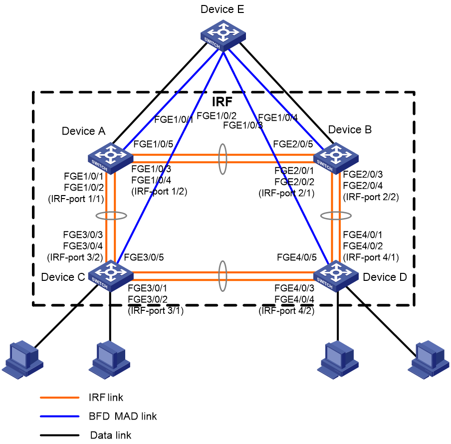
Procedure
1. Configure Device A:
# Shut down the physical interfaces used for IRF links.
<Sysname> system-view
[Sysname] interface range fortygige 1/0/1 to fortygige 1/0/4
[Sysname-if-range] shutdown
[Sysname-if-range] quit
# Bind FortyGigE 1/0/1 and FortyGigE 1/0/2 to IRF-port 1/1.
[Sysname] irf-port 1/1
[Sysname-irf-port1/1] port group interface fortygige 1/0/1
[Sysname-irf-port1/1] port group interface fortygige 1/0/2
[Sysname-irf-port1/1] quit
# Bind FortyGigE 1/0/3 and FortyGigE 1/0/4 to IRF-port 1/2.
[Sysname] irf-port 1/2
[Sysname-irf-port1/2] port group interface fortygige 1/0/3
[Sysname-irf-port1/2] port group interface fortygige 1/0/4
[Sysname-irf-port1/2] quit
# Bring up the physical interfaces and save the configuration.
[Sysname] interface range fortygige 1/0/1 to fortygige 1/0/4
[Sysname-if-range] undo shutdown
[Sysname-if-range] quit
[Sysname] save
# Activate the IRF port configuration.
[Sysname] irf-port-configuration active
2. Configure Device B:
# Change the member ID of Device B to 2 and reboot the device to have the change take effect.
<Sysname> system-view
[Sysname] irf member 1 renumber 2
Renumbering the member ID may result in configuration change or loss. Continue? [Y/N]:y
[Sysname] quit
<Sysname> reboot
# Connect Device B to Device A as shown in Figure 15, and log in to Device B. (Details not shown.)
# Shut down the physical interfaces used for IRF links.
<Sysname> system-view
[Sysname] interface range fortygige 2/0/1 to fortygige 2/0/4
[Sysname-if-range] shutdown
[Sysname-if-range] quit
# Bind FortyGigE 2/0/1 and FortyGigE 2/0/2 to IRF-port 2/1.
[Sysname] irf-port 2/1
[Sysname-irf-port2/1] port group interface fortygige 2/0/1
[Sysname-irf-port2/1] port group interface fortygige 2/0/2
[Sysname-irf-port2/1] quit
# Bind FortyGigE 2/0/3 and FortyGigE 2/0/4 to IRF-port 2/2.
[Sysname] irf-port 2/2
[Sysname-irf-port2/2] port group interface fortygige 2/0/3
[Sysname-irf-port2/2] port group interface fortygige 2/0/4
[Sysname-irf-port2/2] quit
# Bring up the physical interfaces and save the configuration.
[Sysname] interface range fortygige 2/0/1 to fortygige 2/0/4
[Sysname-if-range] undo shutdown
[Sysname-if-range] quit
[Sysname] save
# Activate the IRF port configuration.
[Sysname] irf-port-configuration active
The two devices perform master election, and the one that has lost the election reboots to form an IRF fabric with the master.
3. Configure Device C:
# Change the member ID of Device C to 3 and reboot the device to have the change take effect.
<Sysname> system-view
[Sysname] irf member 1 renumber 3
Renumbering the member ID may result in configuration change or loss. Continue? [Y/N]:y
[Sysname] quit
<Sysname> reboot
# Connect Device C to Device A as shown in Figure 15, and log in to Device C. (Details not shown.)
# Shut down the physical interfaces used for IRF links.
<Sysname> system-view
[Sysname] interface range fortygige 3/0/1 to fortygige 3/0/4
[Sysname-if-range] shutdown
[Sysname-if-range] quit
# Bind FortyGigE 3/0/1 and FortyGigE 3/0/2 to IRF-port 3/1.
[Sysname] irf-port 3/1
[Sysname-irf-port3/1] port group interface fortygige 3/0/1
[Sysname-irf-port3/1] port group interface fortygige 3/0/2
[Sysname-irf-port3/1] quit
# Bind FortyGigE 3/0/3 and FortyGigE 3/0/4 to IRF-port 3/2.
[Sysname] irf-port 3/2
[Sysname-irf-port3/2] port group interface fortygige 3/0/3
[Sysname-irf-port3/2] port group interface fortygige 3/0/4
[Sysname-irf-port3/2] quit
# Bring up the physical interfaces and save the configuration.
[Sysname] interface range fortygige 3/0/1 to fortygige 3/0/4
[Sysname-if-range] undo shutdown
[Sysname-if-range] quit
[Sysname] save
# Activate the IRF port configuration.
[Sysname] irf-port-configuration active
Device C reboots to join the IRF fabric.
4. Configure Device D:
# Change the member ID of Device D to 4 and reboot the device to have the change take effect.
<Sysname> system-view
[Sysname] irf member 1 renumber 4
Renumbering the member ID may result in configuration change or loss. Continue? [Y/N]:y
[Sysname] quit
<Sysname> reboot
# Connect Device D to Device B and Device C as shown in Figure 15, and log in to Device D. (Details not shown.)
# Shut down the physical interfaces used for IRF links.
<Sysname> system-view
[Sysname] interface range fortygige 4/0/1 to fortygige 4/0/4
[Sysname-if-range] shutdown
[Sysname-if-range] quit
# Bind FortyGigE 4/0/1 and FortyGigE 4/0/2 to IRF-port 4/1.
[Sysname] irf-port 4/1
[Sysname-irf-port4/1] port group interface fortygige 4/0/1
[Sysname-irf-port4/1] port group interface fortygige 4/0/2
[Sysname-irf-port4/1] quit
# Bind FortyGigE 4/0/3 and FortyGigE 4/0/4 to IRF-port 4/2.
[Sysname] irf-port 4/2
[Sysname-irf-port4/2] port group interface fortygige 4/0/3
[Sysname-irf-port4/2] port group interface fortygige 4/0/4
[Sysname-irf-port4/2] quit
# Bring up the physical interfaces and save the configuration.
[Sysname] interface range fortygige 4/0/1 to fortygige 4/0/4
[Sysname-if-range] undo shutdown
[Sysname-if-range] quit
[Sysname] save
# Activate the IRF port configuration.
[Sysname] irf-port-configuration active
Device D reboots to join the IRF fabric. A four-chassis IRF fabric is formed.
5. Configure BFD MAD on the IRF fabric:
# Create VLAN 3, and add FortyGigE 1/0/5, FortyGigE 2/0/5, FortyGigE 3/0/5, and FortyGigE 4/0/5 to VLAN 3.
[Sysname] vlan 3
[Sysname-vlan3] port fortygige 1/0/5 fortygige 2/0/5 fortygige 3/0/5 fortygige 4/0/5
[Sysname-vlan3] quit
# Create VLAN-interface 3, and configure a MAD IP address for each member device on the VLAN interface.
[Sysname] interface vlan-interface 3
[Sysname-Vlan-interface3] mad bfd enable
[Sysname-Vlan-interface3] mad ip address 192.168.2.1 24 member 1
[Sysname-Vlan-interface3] mad ip address 192.168.2.2 24 member 2
[Sysname-Vlan-interface3] mad ip address 192.168.2.3 24 member 3
[Sysname-Vlan-interface3] mad ip address 192.168.2.4 24 member 4
[Sysname-Vlan-interface3] quit
# Disable the spanning tree feature on FortyGigE 1/0/5, FortyGigE 2/0/5, FortyGigE 3/0/5, and FortyGigE 4/0/5.
[Sysname] interface range fortygige 1/0/5 fortygige 2/0/5 fortygige 3/0/5 fortygige 4/0/5
[Sysname-if-range] undo stp enable
[Sysname-if-range] quit
6. Configure Device E as the intermediate device:
# Create VLAN 3, and assign FortyGigE 1/0/1, FortyGigE 1/0/2, FortyGigE 1/0/3, and FortyGigE 1/0/4 to VLAN 3 for forwarding BFD MAD packets.
<DeviceE> system-view
[DeviceE] vlan 3
[DeviceE-vlan3] port fortygige 1/0/1 to fortygige 1/0/4
[DeviceE-vlan3] quit
Example: Configuring an IRF fabric with ARP MAD enabled on a VLAN interface
Network configuration
As shown in Figure 16, set up a four-chassis IRF fabric in the enterprise network.
· Configure ARP MAD on the IRF fabric and use the links connected to Device E for transmitting ARP MAD packets.
· To prevent loops, run the spanning tree feature between Device E and the IRF fabric.

Procedure
1. Configure Device A:
# Shut down the physical interfaces used for IRF links.
<Sysname> system-view
[Sysname] interface range fortygige 1/0/1 to fortygige 1/0/4
[Sysname-if-range] shutdown
[Sysname-if-range] quit
# Bind FortyGigE 1/0/1 and FortyGigE 1/0/2 to IRF-port 1/1.
[Sysname] irf-port 1/1
[Sysname-irf-port1/1] port group interface fortygige 1/0/1
[Sysname-irf-port1/1] port group interface fortygige 1/0/2
[Sysname-irf-port1/1] quit
# Bind FortyGigE 1/0/3 and FortyGigE 1/0/4 to IRF-port 1/2.
[Sysname] irf-port 1/2
[Sysname-irf-port1/2] port group interface fortygige 1/0/3
[Sysname-irf-port1/2] port group interface fortygige 1/0/4
[Sysname-irf-port1/2] quit
# Bring up the physical interfaces and save the configuration.
[Sysname] interface range fortygige 1/0/1 to fortygige 1/0/4
[Sysname-if-range] undo shutdown
[Sysname-if-range] quit
[Sysname] save
# Activate the IRF port configuration.
[Sysname] irf-port-configuration active
2. Configure Device B:
# Change the member ID of Device B to 2 and reboot the device to have the change take effect.
<Sysname> system-view
[Sysname] irf member 1 renumber 2
Renumbering the member ID may result in configuration change or loss. Continue? [Y/N]:y
[Sysname] quit
<Sysname> reboot
# Connect Device B to Device A as shown in Figure 16, and log in to Device B. (Details not shown.)
# Shut down the physical interfaces used for IRF links.
<Sysname> system-view
[Sysname] interface range fortygige 2/0/1 to fortygige 2/0/4
[Sysname-if-range] shutdown
[Sysname-if-range] quit
# Bind FortyGigE 2/0/1 and FortyGigE 2/0/2 to IRF-port 2/1.
[Sysname] irf-port 2/1
[Sysname-irf-port2/1] port group interface fortygige 2/0/1
[Sysname-irf-port2/1] port group interface fortygige 2/0/2
[Sysname-irf-port2/1] quit
# Bind FortyGigE 2/0/3 and FortyGigE 2/0/4 to IRF-port 2/2.
[Sysname] irf-port 2/2
[Sysname-irf-port2/2] port group interface fortygige 2/0/3
[Sysname-irf-port2/2] port group interface fortygige 2/0/4
[Sysname-irf-port2/2] quit
# Bring up the physical interfaces and save the configuration.
[Sysname] interface range fortygige 2/0/1 to fortygige 2/0/4
[Sysname-if-range] undo shutdown
[Sysname-if-range] quit
[Sysname] save
# Activate the IRF port configuration.
[Sysname] irf-port-configuration active
The two devices perform master election, and the one that has lost the election reboots to form an IRF fabric with the master.
3. Configure Device C:
# Change the member ID of Device C to 3 and reboot the device to have the change take effect.
<Sysname> system-view
[Sysname] irf member 1 renumber 3
Renumbering the member ID may result in configuration change or loss. Continue? [Y/N]:y
[Sysname] quit
<Sysname> reboot
# Connect Device C to Device A as shown in Figure 16, and log in to Device C. (Details not shown.)
# Shut down the physical interfaces used for IRF links.
<Sysname> system-view
[Sysname] interface range fortygige 3/0/1 to fortygige 3/0/4
[Sysname-if-range] shutdown
[Sysname-if-range] quit
# Bind FortyGigE 3/0/1 and FortyGigE 3/0/2 to IRF-port 3/1.
[Sysname] irf-port 3/1
[Sysname-irf-port3/1] port group interface fortygige 3/0/1
[Sysname-irf-port3/1] port group interface fortygige 3/0/2
[Sysname-irf-port3/1] quit
# Bind FortyGigE 3/0/3 and FortyGigE 3/0/4 to IRF-port 3/2.
[Sysname] irf-port 3/2
[Sysname-irf-port3/2] port group interface fortygige 3/0/3
[Sysname-irf-port3/2] port group interface fortygige 3/0/4
[Sysname-irf-port3/2] quit
# Bring up the physical interfaces and save the configuration.
[Sysname] interface range fortygige 3/0/1 to fortygige 3/0/4
[Sysname-if-range] undo shutdown
[Sysname-if-range] quit
[Sysname] save
# Activate the IRF port configuration.
[Sysname] irf-port-configuration active
Device C reboots to join the IRF fabric.
4. Configure Device D:
# Change the member ID of Device D to 4 and reboot the device to have the change take effect.
<Sysname> system-view
[Sysname] irf member 1 renumber 4
Renumbering the member ID may result in configuration change or loss. Continue? [Y/N]:y
[Sysname] quit
<Sysname> reboot
# Connect Device D to Device B and Device C as shown in Figure 16, and log in to Device D. (Details not shown.)
# Shut down the physical interfaces used for IRF links.
<Sysname> system-view
[Sysname] interface range fortygige 4/0/1 to fortygige 4/0/4
[Sysname-if-range] shutdown
[Sysname-if-range] quit
# Bind FortyGigE 4/0/1 and FortyGigE 4/0/2 to IRF-port 4/1.
[Sysname] irf-port 4/1
[Sysname-irf-port4/1] port group interface fortygige 4/0/1
[Sysname-irf-port4/1] port group interface fortygige 4/0/2
[Sysname-irf-port4/1] quit
# Bind FortyGigE 4/0/3 and FortyGigE 4/0/4 to IRF-port 4/2.
[Sysname] irf-port 4/2
[Sysname-irf-port4/2] port group interface fortygige 4/0/3
[Sysname-irf-port4/2] port group interface fortygige 4/0/4
[Sysname-irf-port4/2] quit
# Bring up the physical interfaces and save the configuration.
[Sysname] interface range fortygige 4/0/1 to fortygige 4/0/4
[Sysname-if-range] undo shutdown
[Sysname-if-range] quit
[Sysname] save
# Activate the IRF port configuration.
[Sysname] irf-port-configuration active
Device D reboots to join the IRF fabric. A four-chassis IRF fabric is formed.
5. Configure ARP MAD on the IRF fabric:
# Enable the spanning tree feature globally. Map the ARP MAD VLAN to MSTI 1 in the MST region.
<Sysname> system-view
[Sysname] stp global enable
[Sysname] stp region-configuration
[Sysname-mst-region] region-name arpmad
[Sysname-mst-region] instance 1 vlan 3
[Sysname-mst-region] active region-configuration
[Sysname-mst-region] quit
# Configure the IRF fabric to change its bridge MAC address as soon as the address owner leaves.
[Sysname] undo irf mac-address persistent
# Set the domain ID of the IRF fabric to 1.
[Sysname] irf domain 1
# Create VLAN 3, and assign FortyGigE 1/0/5, FortyGigE 2/0/5, FortyGigE 3/0/5, and FortyGigE 4/0/5 to VLAN 3.
[Sysname] vlan 3
[Sysname-vlan3] port fortygige 1/0/5 fortygige 2/0/5 fortygige 3/0/5 fortygige 4/0/5
[Sysname-vlan3] quit
# Create VLAN-interface 3, assign it an IP address, and enable ARP MAD on the interface.
[Sysname] interface vlan-interface 3
[Sysname-Vlan-interface3] ip address 192.168.2.1 24
[Sysname-Vlan-interface3] mad arp enable
You need to assign a domain ID (range: 0-4294967295)
[Current domain ID is: 1]:
The assigned domain ID is: 1
6. Configure Device E as the intermediate device:
|
|
CAUTION: If the intermediate device is also in an IRF fabric, assign the two IRF fabrics different domain IDs for correct split detection. False detection causes IRF split. |
# Enable the spanning tree feature globally. Map the ARP MAD VLAN to MSTI 1 in the MST region.
<DeviceE> system-view
[DeviceE] stp global enable
[DeviceE] stp region-configuration
[DeviceE-mst-region] region-name arpmad
[DeviceE-mst-region] instance 1 vlan 3
[DeviceE-mst-region] active region-configuration
[DeviceE-mst-region] quit
# Create VLAN 3, and assign FortyGigE 1/0/1, FortyGigE 1/0/2, FortyGigE 1/0/3, and FortyGigE 1/0/4 to VLAN 3 for forwarding ARP MAD packets.
[DeviceE] vlan 3
[DeviceE-vlan3] port fortygige 1/0/1 to fortygige 1/0/4
[DeviceE-vlan3] quit
Example: Configuring an IRF fabric with ND MAD enabled on a VLAN interface
Network configuration
As shown in Figure 17, set up a four-chassis IRF fabric in the IPv6 enterprise network.
· Configure ND MAD on the IRF fabric and use the links connected to Device E for transmitting ND MAD packets.
· To prevent loops, run the spanning tree feature between Device E and the IRF fabric.
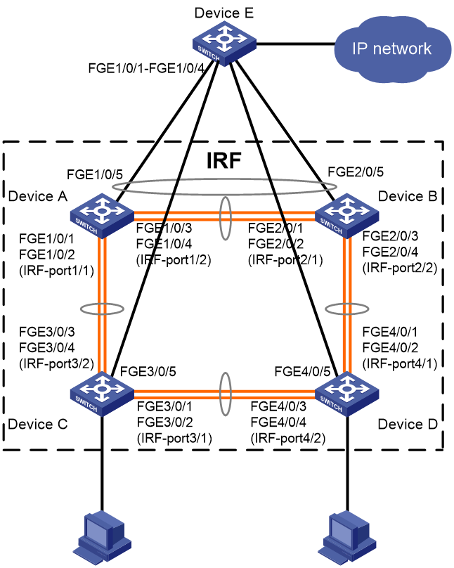
Procedure
1. Configure Device A:
# Shut down the physical interfaces used for IRF links.
<Sysname> system-view
[Sysname] interface range fortygige 1/0/1 to fortygige 1/0/4
[Sysname-if-range] shutdown
[Sysname-if-range] quit
# Bind FortyGigE 1/0/1 and FortyGigE 1/0/2 to IRF-port 1/1.
[Sysname] irf-port 1/1
[Sysname-irf-port1/1] port group interface fortygige 1/0/1
[Sysname-irf-port1/1] port group interface fortygige 1/0/2
[Sysname-irf-port1/1] quit
# Bind FortyGigE 1/0/3 and FortyGigE 1/0/4 to IRF-port 1/2.
[Sysname] irf-port 1/2
[Sysname-irf-port1/2] port group interface fortygige 1/0/3
[Sysname-irf-port1/2] port group interface fortygige 1/0/4
[Sysname-irf-port1/2] quit
# Bring up the physical interfaces and save the configuration.
[Sysname] interface range fortygige 1/0/1 to fortygige 1/0/4
[Sysname-if-range] undo shutdown
[Sysname-if-range] quit
[Sysname] save
# Activate the IRF port configuration.
[Sysname] irf-port-configuration active
2. Configure Device B:
# Change the member ID of Device B to 2 and reboot the device to have the change take effect.
<Sysname> system-view
[Sysname] irf member 1 renumber 2
Renumbering the member ID may result in configuration change or loss. Continue? [Y/N]:y
[Sysname] quit
<Sysname> reboot
# Connect Device B to Device A as shown in Figure 17, and log in to Device B. (Details not shown.)
# Shut down the physical interfaces used for IRF links.
<Sysname> system-view
[Sysname] interface range fortygige 2/0/1 to fortygige 2/0/4
[Sysname-if-range] shutdown
[Sysname-if-range] quit
# Bind FortyGigE 2/0/1 and FortyGigE 2/0/2 to IRF-port 2/1.
[Sysname] irf-port 2/1
[Sysname-irf-port2/1] port group interface fortygige 2/0/1
[Sysname-irf-port2/1] port group interface fortygige 2/0/2
[Sysname-irf-port2/1] quit
# Bind FortyGigE 2/0/3 and FortyGigE 2/0/4 to IRF-port 2/2.
[Sysname] irf-port 2/2
[Sysname-irf-port2/2] port group interface fortygige 2/0/3
[Sysname-irf-port2/2] port group interface fortygige 2/0/4
[Sysname-irf-port2/2] quit
# Bring up the physical interfaces and save the configuration.
[Sysname] interface range fortygige 2/0/1 to fortygige 2/0/4
[Sysname-if-range] undo shutdown
[Sysname-if-range] quit
[Sysname] save
# Activate the IRF port configuration.
[Sysname] irf-port-configuration active
The two devices perform master election, and the one that has lost the election reboots to form an IRF fabric with the master.
3. Configure Device C:
# Change the member ID of Device C to 3 and reboot the device to have the change take effect.
<Sysname> system-view
[Sysname] irf member 1 renumber 3
Renumbering the member ID may result in configuration change or loss. Continue? [Y/N]:y
[Sysname] quit
<Sysname> reboot
# Connect Device C to Device A as shown in Figure 17, and log in to Device C. (Details not shown.)
# Shut down the physical interfaces used for IRF links.
<Sysname> system-view
[Sysname] interface range fortygige 3/0/1 to fortygige 3/0/4
[Sysname-if-range] shutdown
[Sysname-if-range] quit
# Bind FortyGigE 3/0/1 and FortyGigE 3/0/2 to IRF-port 3/1.
[Sysname] irf-port 3/1
[Sysname-irf-port3/1] port group interface fortygige 3/0/1
[Sysname-irf-port3/1] port group interface fortygige 3/0/2
[Sysname-irf-port3/1] quit
# Bind FortyGigE 3/0/3 and FortyGigE 3/0/4 to IRF-port 3/2.
[Sysname] irf-port 3/2
[Sysname-irf-port3/2] port group interface fortygige 3/0/3
[Sysname-irf-port3/2] port group interface fortygige 3/0/4
[Sysname-irf-port3/2] quit
# Bring up the physical interfaces and save the configuration.
[Sysname] interface range fortygige 3/0/1 to fortygige 3/0/4
[Sysname-if-range] undo shutdown
[Sysname-if-range] quit
[Sysname] save
# Activate the IRF port configuration.
[Sysname] irf-port-configuration active
Device C reboots to join the IRF fabric.
4. Configure Device D:
# Change the member ID of Device D to 4 and reboot the device to have the change take effect.
<Sysname> system-view
[Sysname] irf member 1 renumber 4
Renumbering the member ID may result in configuration change or loss. Continue? [Y/N]:y
[Sysname] quit
<Sysname> reboot
# Connect Device D to Device B and Device C as shown in Figure 17, and log in to Device D. (Details not shown.)
# Shut down the physical interfaces used for IRF links.
<Sysname> system-view
[Sysname] interface range fortygige 4/0/1 to fortygige 4/0/4
[Sysname-if-range] shutdown
[Sysname-if-range] quit
# Bind FortyGigE 4/0/1 and FortyGigE 4/0/2 to IRF-port 4/1.
[Sysname] irf-port 4/1
[Sysname-irf-port4/1] port group interface fortygige 4/0/1
[Sysname-irf-port4/1] port group interface fortygige 4/0/2
[Sysname-irf-port4/1] quit
# Bind FortyGigE 4/0/3 and FortyGigE 4/0/4 to IRF-port 4/2.
[Sysname] irf-port 4/2
[Sysname-irf-port4/2] port group interface fortygige 4/0/3
[Sysname-irf-port4/2] port group interface fortygige 4/0/4
[Sysname-irf-port4/2] quit
# Bring up the physical interfaces and save the configuration.
[Sysname] interface range fortygige 4/0/1 to fortygige 4/0/4
[Sysname-if-range] undo shutdown
[Sysname-if-range] quit
[Sysname] save
# Activate the IRF port configuration.
[Sysname] irf-port-configuration active
Device D reboots to join the IRF fabric. A four-chassis IRF fabric is formed.
5. Configure ND MAD on the IRF fabric:
# Enable the spanning tree feature globally. Map the ND MAD VLAN to MSTI 1 in the MST region.
<Sysname> system-view
[Sysname] stp global enable
[Sysname] stp region-configuration
[Sysname-mst-region] region-name ndmad
[Sysname-mst-region] instance 1 vlan 3
[Sysname-mst-region] active region-configuration
[Sysname-mst-region] quit
# Configure the IRF fabric to change its bridge MAC address as soon as the address owner leaves.
[Sysname] undo irf mac-address persistent
# Set the domain ID of the IRF fabric to 1.
[Sysname] irf domain 1
# Create VLAN 3, and add FortyGigE 1/0/5, FortyGigE 2/0/5, FortyGigE 3/0/5, and FortyGigE 4/0/5 to VLAN 3.
[Sysname] vlan 3
[Sysname-vlan3] port fortygige 1/0/5 fortygige 2/0/5 fortygige 3/0/5 fortygige 4/0/5
[Sysname-vlan3] quit
# Create VLAN-interface 3, assign it an IPv6 address, and enable ND MAD on the interface.
[Sysname] interface vlan-interface 3
[Sysname-Vlan-interface3] ipv6 address 2001::1 64
[Sysname-Vlan-interface3] mad nd enable
You need to assign a domain ID (range: 0-4294967295)
[Current domain ID is: 1]:
The assigned domain ID is: 1
6. Configure Device E as the intermediate device:
|
|
CAUTION: If the intermediate device is also in an IRF fabric, assign the two IRF fabrics different domain IDs for correct split detection. False detection causes IRF split. |
# Enable the spanning tree feature globally. Map the ND MAD VLAN to MSTI 1 in the MST region.
<DeviceE> system-view
[DeviceE] stp global enable
[DeviceE] stp region-configuration
[DeviceE-mst-region] region-name ndmad
[DeviceE-mst-region] instance 1 vlan 3
[DeviceE-mst-region] active region-configuration
[DeviceE-mst-region] quit
# Create VLAN 3, and add FortyGigE 1/0/1, FortyGigE 1/0/2, FortyGigE 1/0/3, and FortyGigE 1/0/4 to VLAN 3 for forwarding ND MAD packets.
[DeviceE] vlan 3
[DeviceE-vlan3] port fortygige 1/0/1 to fortygige 1/0/4
[DeviceE-vlan3] quit
Example: Configuring an IRF fabric with ARP MAD and management IP configured on the same management Ethernet port
|
|
IMPORTANT: This example is also applicable to a two-chassis IRF fabric running ND MAD, except that you must configure ND MAD differently. |
Network configuration
As shown in Figure 18, use Device A and Device B to set up a two-chassis IRF fabric.
Use management Ethernet port M-GigabitEthernet 0/0/0 to perform ARP MAD for IRF split detection and to provide device access for management purposes.
Configure management IP addresses for the IRF fabric and each member device on the management port to meet the following requirements:
· The administrator can use the same management IP address to access the IRF fabric before and after an active/subordinate switchover.
· The administrator can access each member device for failure recovery through their respective management IP addresses after the IRF fabric splits.
Restrictions and guidelines
When you configure management IP addresses, follow these restrictions and guidelines:
· To make sure you can access the IRF fabric at the same IP address after a master/subordinate switchover, use the ip address ip-address { mask-length | mask } command to configure a management IP address on the management port, in this example, on M-GigabitEthernet 0/0/0. You can use this address to access the IRF fabric as long as the fabric has not split. This address might be inaccesible for an IP conflict after the IRF fabric splits, because it exists on all member devices. In the context of IRF, this address is called a global management IP address.
· To access each member device for failure recovery after the IRF fabric splits, use the ip address ip-address { mask-length | mask } irf-member member-id command to configure a management IP address for each member device on the management port, in this example, on M-GigabitEthernet 0/0/0. In the context of IRF, this address is called a member-specific management IP address.
· Make sure the management IP addresses assigned to all IRF member devices on the same management Ethernet port belong to the same subnet. Make sure the management IP addresses assigned to an IRF member device on different management Ethernet ports belong to different subnets.
· You must manually make sure the management IP addresses configured on the subordinate devices will not cause IP address conflicts on the network. When the IRF fabric is running correctly, only the IP addresses of the management Ethernet ports on the master device take effect. The management IP addresses of the management Ethernet ports on the subordinate devices do not take effect. If a management IP address on a subordinate device conflicts with an IP address in the network, the system cannot detect the IP conflict, causing network issues after an IRF split.
|
|
NOTE: When the IRF fabric is integrated, you can access the IRF fabric by using either the global management IP address or the management IP address specific to the master device. As a best practice to prevent the management IP address from changing upon a master/subordinate switchover, use the global management IP address as long as the IRF fabric is integrated. |
When you configure ARP MAD on a management Ethernet port, follow the restrictions and guidelines in "Configuring ARP MAD."
Setting up the IRF fabric
1. Configure Device A:
# Shut down the physical interfaces used for IRF connection. This example uses FortyGigE 1/0/1 and FortyGigE 1/0/2 for IRF connection.
<DeviceA> system-view
[DeviceA] interface range fortygige 1/0/1 to fortygige 1/0/2
[DeviceA-if-range] shutdown
[DeviceA-if-range] quit
# Bind FortyGigE 1/0/1 and FortyGigE 1/0/2 to IRF-port 1/2.
[DeviceA] irf-port 1/2
[DeviceA-irf-port1/2] port group interface fortygige 1/0/1
[DeviceA-irf-port1/2] port group interface fortygige 1/0/2
[DeviceA-irf-port1/2] quit
# Bring up the physical interfaces.
[DeviceA] interface range fortygige 1/0/1 to fortygige 1/0/2
[DeviceA-if-range] undo shutdown
[DeviceA-if-range] quit
# Save the running configuration to the next-startup configuration file.
[DeviceA] quit
<DeviceA> save
# Activate the IRF port configuration.
<DeviceA> system-view
[DeviceA] irf-port-configuration active
2. Configure Device B:
# Assign member ID 2 to Device B, and reboot the device to have the change take effect.
<DeviceB> system-view
[DeviceB] irf member 1 renumber 2
Renumbering the member ID may result in configuration change or loss. Continue? [Y/N]:y
[DeviceB] quit
<DeviceB> reboot
# Shut down the physical interfaces used for IRF connection. This example uses FortyGigE 2/0/1 and FortyGigE 2/0/2 for IRF connection.
<DeviceB> system-view
[DeviceB] interface range fortygige 2/0/1 to fortygige 2/0/2
[DeviceB-if-range] shutdown
[DeviceB-if-range] quit
# Bind FortyGigE 2/0/1 and FortyGigE 2/0/2 to IRF-port 2/1.
[DeviceB] irf-port 2/1
[DeviceB-irf-port2/1] port group interface fortygige 2/0/1
[DeviceB-irf-port2/1] port group interface fortygige 2/0/2
[DeviceB-irf-port2/1] quit
# Bring up the physical interfaces.
[DeviceB] interface range fortygige 2/0/1 to fortygige 2/0/2
[DeviceB-if-range] undo shutdown
[DeviceB-if-range] quit
# Save the running configuration to the next-startup configuration file.
[DeviceB] quit
<DeviceB> save
# Connect Device B to Device A, as shown in Figure 18.
# Activate the IRF port configuration.
<DeviceB> system-view
[DeviceB] irf-port-configuration active
Device A and Device B perform master election. The device that has failed master election automatically reboots to form an IRF fabric with the other device. A two-chassis IRF fabric is formed.
Configuring management IP addresses
# Assign IP address 192.168.1.1/24 to the IRF fabric on management Ethernet port M-GigabitEthernet 0/0/0.
<IRF> system-view
[IRF] interface m-gigabitethernet 0/0/0
[IRF-M-GigabitEthernet0/0/0] ip address 192.168.1.1 24
# On management Ethernet port M-GigabitEthernet 0/0/0, assign IP addresses 192.168.1.101/24 and 192.168.1.102/24 to IRF member device 1 (Device A) and IRF member device 2 (Device B), respectively. After the IRF fabric splits, the administrator can use IP addresses 192.168.1.101/24 and 192.168.1.102/24 to log in to Device A and Device B, respectively.
[IRF-M-GigabitEthernet0/0/0] ip address 192.168.1.101 24 irf-member 1
[IRF-M-GigabitEthernet0/0/0] ip address 192.168.1.102 24 irf-member 2
[IRF-M-GigabitEthernet0/0/0] quit
# Exclude management Ethernet port M-GigabitEthernet 0/0/0 from being shut down by MAD upon detection of multi-active collisions.
[IRF] mad exclude interface m-gigabitethernet 0/0/0
Configuring ARP MAD
1. Configure the IRF fabric:
# Configure the IRF fabric to change its bridge MAC address as soon as the address owner leaves.
[IRF] undo irf mac-address persistent
# Set the domain ID of the IRF fabric to 1.
[IRF] irf domain 1
# Enable ARP MAD on management Ethernet port M-GigabitEthernet 0/0/0.
[IRF] interface m-gigabitethernet 0/0/0
[IRF-M-GigabitEthernet0/0/0] mad arp enable
You need to assign a domain ID (range: 0-4294967295)
[Current domain ID is: 1]:
The assigned domain ID is: 1
[IRF-M-GigabitEthernet0/0/0] quit
# Save the running configuration to the next-startup configuration file.
[IRF] save
2. Configure Device C (a switch that supports ARP) as the intermediate device:
|
|
CAUTION: If the intermediate device is also in an IRF fabric, assign the two IRF fabrics different domain IDs for correct split detection. False detection causes IRF split. |
# Create VLAN 100.
<DeviceC> system-view
[DeviceC] vlan 100
# Assign GigabitEthernet 1/0/1 and GigabitEthernet 1/0/2 to VLAN 100 for forwarding ARP MAD packets.
[DeviceC-vlan100] port gigabitethernet 1/0/1 to gigabitethernet 1/0/2
[DeviceC-vlan100] quit
Verifying the configuration
# Disconnect the IRF links between Device A and Device B. Verify that you can use 192.168.1.101 and 192.168.1.102 to log in to Device A and Device B, respectively. (Details not shown.)
# Execute the display mad verbose command on Device A and Device B to verify that MAD is correctly functioning, as follows:
· The Multi-active recovery state field displays Yes on one device and displays No on the other device.
· On each device, the IRF physical interfaces and management Ethernet port M-GigabitEthernet 0/0/0 are excluded from being shut down by MAD.
# Execute the display interface brief command on Device A and Device B to verify that the MAD shutdown action is performed correctly, as follows:
· On the device in Recovery state, all network interfaces have been shut down by MAD except the IRF physical interfaces and management Ethernet port M-GigabitEthernet 0/0/0.
· On the device not in Recovery state, no network interfaces are shut down by MAD.
Example: Configuring an IRF fabric with BFD MAD and management IP configured on separate management Ethernet ports
|
|
IMPORTANT: This example is also applicable to a two-chassis IRF fabric running ARP MAD or ND MAD, except that you must configure ARP MAD and ND MAD differently. |
Network configuration
As shown in Figure 19, use Device A and Device B to set up a two-chassis IRF fabric.
Use management Ethernet port M-GigabitEthernet 0/0/0 on Device A and Device B for device management purposes. Configure management IP addresses for the IRF fabric and each member device on the management port to meet the following requirements:
· The administrator can use the same management IP address to access the IRF fabric before and after an active/subordinate switchover.
· The administrator can access each member device for failure recovery through their respective management IP addresses after the IRF fabric splits.
Use management Ethernet port M-GigabitEthernet 0/0/1 to perform BFD MAD for IRF split detection.
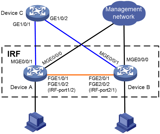
Restrictions and guidelines
When you configure management IP addresses, follow these restrictions and guidelines:
· To make sure you can access the IRF fabric at the same IP address after a master/subordinate switchover, use the ip address ip-address { mask-length | mask } command to configure a management IP address on the management port, in this example, on M-GigabitEthernet 0/0/0. You can use this address to access the IRF fabric as long as the fabric has not split. This address might be inaccesible for an IP conflict after the IRF fabric splits, because it exists on all member devices. In the context of IRF, this address is called a global management IP address.
· To access each member device for failure recovery after the IRF fabric splits, use the ip address ip-address { mask-length | mask } irf-member member-id command to configure a management IP address for each member device on the management port, in this example, on M-GigabitEthernet 0/0/0. In the context of IRF, this address is called a member-specific management IP address.
· Make sure the management IP addresses assigned to all IRF member devices on the same management Ethernet port belong to the same subnet. Make sure the management IP addresses assigned to an IRF member device on different management Ethernet ports belong to different subnets.
· You must manually make sure the management IP addresses configured on the subordinate devices will not cause IP address conflicts on the network. When the IRF fabric is running correctly, only the IP addresses of the management Ethernet ports on the master device take effect. The management IP addresses of the management Ethernet ports on the subordinate devices do not take effect. If a management IP address on a subordinate device conflicts with an IP address in the network, the system cannot detect the IP conflict, causing network issues after an IRF split.
|
|
NOTE: When the IRF fabric is integrated, you can access the IRF fabric by using either the global management IP address or the management IP address specific to the master device. As a best practice to prevent the management IP address from changing upon a master/subordinate switchover, use the global management IP address as long as the IRF fabric is integrated. |
When you configure BFD MAD on a management Ethernet port, follow the restrictions and guidelines in "Configuring BFD MAD."
Setting up the IRF fabric
1. Configure Device A:
# Shut down the physical interfaces used for IRF connection. This example uses FortyGigE 1/0/1 and FortyGigE 1/0/2 for IRF connection.
<DeviceA> system-view
[DeviceA] interface range fortygige 1/0/1 to fortygige 1/0/2
[DeviceA-if-range] shutdown
[DeviceA-if-range] quit
# Bind FortyGigE 1/0/1 and FortyGigE 1/0/2 to IRF-port 1/2.
[DeviceA] irf-port 1/2
[DeviceA-irf-port1/2] port group interface fortygige 1/0/1
[DeviceA-irf-port1/2] port group interface fortygige 1/0/2
[DeviceA-irf-port1/2] quit
# Bring up the physical interfaces.
[DeviceA] interface range fortygige 1/0/1 to fortygige 1/0/2
[DeviceA-if-range] undo shutdown
[DeviceA-if-range] quit
# Save the running configuration to the next-startup configuration file.
[DeviceA] quit
<DeviceA> save
# Activate the IRF port configuration.
<DeviceA> system-view
[DeviceA] irf-port-configuration active
2. Configure Device B:
# Assign member ID 2 to Device B, and reboot the device to have the change take effect.
<DeviceB> system-view
[DeviceB] irf member 1 renumber 2
Renumbering the member ID may result in configuration change or loss. Continue? [Y/N]:y
[DeviceB] quit
<DeviceB> reboot
# Shut down the physical interfaces used for IRF connection. This example uses FortyGigE 2/0/1 and FortyGigE 2/0/2 for IRF connection.
<DeviceB> system-view
[DeviceB] interface range fortygige 2/0/1 to fortygige 2/0/2
[DeviceB-if-range] shutdown
[DeviceB-if-range] quit
# Bind FortyGigE 2/0/1 and FortyGigE 2/0/2 to IRF-port 2/1.
[DeviceB] irf-port 2/1
[DeviceB-irf-port2/1] port group interface fortygige 2/0/1
[DeviceB-irf-port2/1] port group interface fortygige 2/0/2
[DeviceB-irf-port2/1] quit
# Bring up the physical interfaces.
[DeviceB] interface range fortygige 2/0/1 to fortygige 2/0/2
[DeviceB-if-range] undo shutdown
[DeviceB-if-range] quit
# Save the running configuration to the next-startup configuration file.
[DeviceB] quit
<DeviceB> save
# Connect Device B to Device A, as shown in Figure 19.
# Activate the IRF port configuration.
<DeviceB> system-view
[DeviceB] irf-port-configuration active
Device A and Device B perform master election. The device that has failed master election automatically reboots to form an IRF fabric with the other device.
Configuring management IP addresses
# Assign IP address 192.168.1.1/24 to the IRF fabric on management Ethernet port M-GigabitEthernet 0/0/0.
<IRF> system-view
[IRF] interface m-gigabitethernet 0/0/0
[IRF-M-GigabitEthernet0/0/0] ip address 192.168.1.1 24
# On management Ethernet port M-GigabitEthernet 0/0/0, assign IP addresses 192.168.1.101/24 and 192.168.1.102/24 to IRF member device 1 (Device A) and IRF member device 2 (Device B), respectively. After the IRF fabric splits, the administrator can use IP addresses 192.168.1.101/24 and 192.168.1.102/24 to log in to Device A and Device B, respectively.
[IRF-M-GigabitEthernet0/0/0] ip address 192.168.1.101 24 irf-member 1
[IRF-M-GigabitEthernet0/0/0] ip address 192.168.1.102 24 irf-member 2
[IRF-M-GigabitEthernet0/0/0] quit
# Exclude management Ethernet port M-GigabitEthernet 0/0/0 from being shut down by MAD upon detection of multi-active collisions.
[IRF] mad exclude interface m-gigabitethernet 0/0/0
Configuring BFD MAD
1. Configure the IRF fabric:
# Assign a MAD IP address to each IRF member device on management Ethernet port M-GigabitEthernet 0/0/1.
[IRF] interface m-gigabitethernet 0/0/1
[IRF-M-GigabitEthernet0/0/1] mad ip address 192.168.2.1 24 member 1
[IRF-M-GigabitEthernet0/0/1] mad ip address 192.168.2.2 24 member 2
# Enable BFD MAD on management Ethernet port M-GigabitEthernet 0/0/1.
[IRF-M-GigabitEthernet0/0/1] mad bfd enable
[IRF-M-GigabitEthernet0/0/1] quit
# Save the running configuration to the next-startup configuration file.
[IRF] save
2. Configure Device C as the intermediate device:
# Create VLAN 100.
<DeviceC> system-view
[DeviceC] vlan 100
# Assign GigabitEthernet 1/0/1 and GigabitEthernet 1/0/2 to VLAN 100 for forwarding BFD MAD packets.
[DeviceC-vlan100] port gigabitethernet 1/0/1 to gigabitethernet 1/0/2
[DeviceC-vlan100] quit
Verifying the configuration
# Disconnect the IRF links between Device A and Device B. Verify that you can use 192.168.1.101 and 192.168.1.102 to log in to Device A and Device B, respectively. (Details not shown.)
# Execute the display mad verbose command on Device A and Device B to verify that MAD is correctly functioning, as follows:
· The Multi-active recovery state field displays Yes on one device and displays No on the other device.
· On each device, the following network interfaces are excluded from being shut down by MAD:
¡ The IRF physical interfaces.
¡ Management Ethernet ports M-GigabitEthernet 0/0/0 and M-GigabitEthernet 0/0/1.
# Execute the display interface brief command on Device A and Device B to verify that the MAD shutdown action is performed correctly, as follows:
· On the device in Recovery state, all network interfaces have been shut down by MAD except the IRF physical interfaces and management Ethernet ports M-GigabitEthernet 0/0/0 and M-GigabitEthernet 0/0/1.
· On the device not in Recovery state, no network interfaces are shut down by MAD.
Example: Removing member devices from an IRF fabric without MAD in place
Network configuration
As shown in Figure 20 or Figure 21, an IRF fabric is in daisy-chain or ring topology. The IRF fabric contains four member devices, in which member 1 is the master device. MAD is not configured on the IRF fabric.
Remove member devices 3 and 4 from the IRF fabric.
Figure 20 Network diagram (daisy-chain topology)
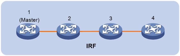
Figure 21 Network diagram (ring topology)
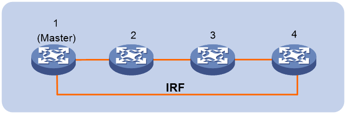
Procedure
1. Enable the IRF fabric to change its bridge MAC address as soon as the address owner leaves the fabric.
<System> system-view
[System] undo irf mac-address persistent
2. Shut down the network interfaces that connect member devices 3 and 4 to the upstream and downstream devices. (Details not shown.)
3. Use one of the following methods to split the IRF fabric into two IRF fabrics (IRF 1 and IRF 2):
¡ Disconnect the physical IRF links between IRF 1 and IRF 2, as shown in Figure 22 or Figure 23.
Figure 22 Disconnecting physical IRF links (daisy-chain topology)
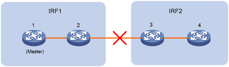
Figure 23 Disconnecting physical IRF links (ring topology)
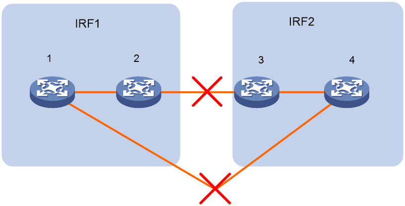
¡ Shut down the IRF physical interfaces that connect IRF 1 and IRF 2, as shown in Figure 22 or Figure 23. (Details not shown.)
The IRF fabric splits into IRF 1 and IRF 2. Because MAD is not configured, both IRF 1 and IRF 2 are active. The member devices in IRF 2 automatically elect a master on split.
4. Handle IRF 2:
¡ To retain IRF 2 in the network, log in to IRF 2, modify the IP addresses that conflict with those on IRF 1 and change its domain ID. (Details not shown.)
¡ To remove IRF 2 from the network, disconnect all physical network connections from the IRF fabric and remove IRF configuration from all member devices in the IRF fabric. (Details not shown.)
5. Bring up the network interfaces that have been shut down on the removed member devices. (Details not shown.)
6. Remove IRF port bindings from unused IRF physical interfaces on IRF 1. (Details not shown.)
Example: Removing member devices from an IRF fabric with MAD in place
Network configuration
As shown in Figure 24 or Figure 25, an IRF fabric is in daisy-chain or ring topology. The IRF fabric contains four member devices, in which member 1 is the master device. MAD is configured on the IRF fabric.
Remove member devices 3 and 4 from the IRF fabric.
Figure 24 Network diagram (daisy-chain topology)
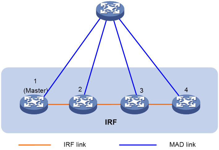
Figure 25 Network diagram (ring topology)
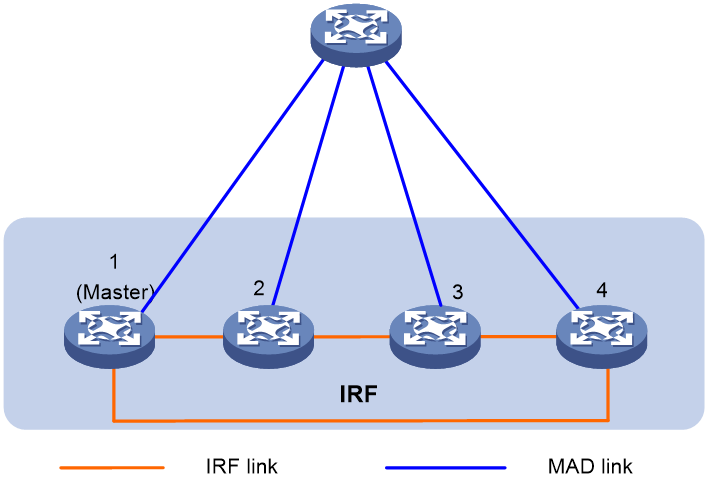
Procedure
1. Enable the IRF fabric to change its bridge MAC address as soon as the address owner leaves the fabric.
<System> system-view
[System] undo irf mac-address persistent
2. Shut down the network interfaces that connect member devices 3 and 4 to the upstream and downstream devices. (Details not shown.)
3. Use one of the following methods to split the IRF fabric into two IRF fabrics (IRF 1 and IRF 2):
¡ Disconnect the physical IRF links between IRF 1 and IRF 2, as shown in Figure 26 or Figure 27.
Figure 26 Disconnecting physical IRF links (daisy-chain topology)
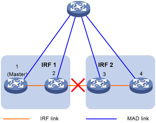
Figure 27 Disconnecting physical IRF links (ring topology)
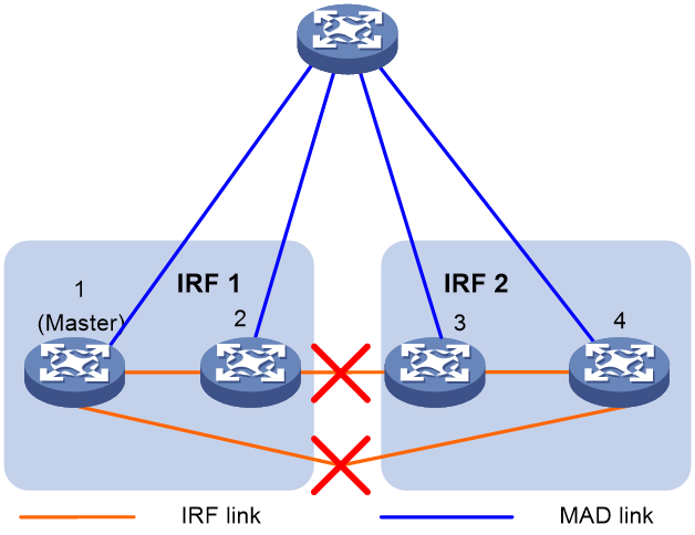
¡ Shut down the IRF physical interfaces that connect IRF 1 and IRF 2, as shown in Figure 26 or Figure 27. (Details not shown.)
The IRF fabric splits into IRF 1 and IRF 2. Because MAD is configured, IRF 1 remains active and IRF 2 is placed in Recovery state and becomes inactive.
4. Handle IRF 2:
¡ To retain IRF 2 in the network, log in to IRF 2, modify the IP addresses that conflict with those on IRF 1, change its domain ID, and recover IRF 2.
<System> system-view
[System] irf domain 2
[System] mad restore
¡ To remove IRF 2 from the network, disconnect all physical network connections from the IRF fabric and remove IRF configuration from all member devices in the IRF fabric. (Details not shown.)
5. Bring up the network interfaces that have been shut down on the removed member devices. (Details not shown.)
6. Remove IRF port bindings from unused IRF physical interfaces on IRF 1. (Details not shown.)
Configuring an IRF 3.1 system
About IRF 3.1
IRF 3.1 integrates multiple lower-layer devices with a higher-layer IRF fabric to provide high-density, low-cost connectivity at the access layer. IRF 3.1 is implemented based on IEEE 802.1BR.
In an IRF 3.1 system, the higher-layer IRF fabric is called the parent fabric and the lower-layer devices are called bridge port extenders (PEXs). You manage and configure the PEXs from the parent fabric as if they were interface modules on the parent fabric.
IRF 3.1 network model
Typically, IRF 3.1 works at the access layer of data centers and large-scale enterprise networks. As shown in Figure 28, the access layer of a network is virtualized into an IRF 3.1 system. The system contains one parent fabric (a two-chassis IRF fabric) and multiple PEXs to provide connectivity for servers and hosts.
Figure 28 IRF 3.1 application scenario
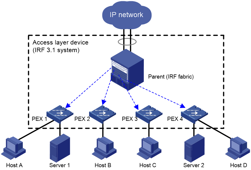
IRF 3.1 benefits
IRF 3.1 provides the following benefits:
· Simplified topology—Devices in an IRF 3.1 system appear as one node. For redundancy and load balancing, a downstream or upstream device can connect to the IRF 3.1 system through multichassis link aggregation. Together with link aggregation, IRF 3.1 creates a loop-free Layer 2 network. The spanning tree feature is not needed among devices in the IRF 3.1 system or on the link aggregations. IRF 3.1 also simplifies the Layer 3 network topology because it reduces the number of routing peers. The network topology does not change when a device is added to or removed from the IRF 3.1 system.
· Single point of management—An IRF 3.1 system is accessible at a single IP address on the network. You can use this IP address to log in through any network port to manage all the devices in the system. For an SNMP NMS, an IRF 3.1 system is one managed network node.
· Network scalability and resiliency—You can increase the number of ports in an IRF 3.1 system by adding PEXs without changing network topology.
· High availability—Each PEX has multiple high-speed physical ports for uplink connectivity to the parent fabric. The links on these ports are aggregated and load balanced automatically.
· Decreased TCO—IRF 3.1 decreases hardware investments and management costs. In an IRF 3.1 system, the parent fabric performs all the management and routing functions, and the PEXs only forward traffic. You can add low-performance devices as PEXs to an IRF 3.1 system for network scalability.
· High software compatibility—The software versions of the parent fabric and PEXs are highly compatible. You can independently upgrade software for the parent and PEXs.
Network topology
You can set up an IRF 3.1 system that contains one tier of PEXs. In this topology, connect each PEX to the parent fabric through a Layer 2 aggregate interface in dynamic aggregation mode.
|
|
IMPORTANT: To avoid loops, do not connect one PEX to another PEX. |
Figure 29 IRF 3.1 network topology with one tier of PEXs
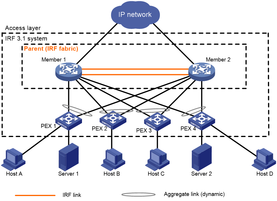
Basic concepts
IRF 3.1 includes IRF concepts and adds the concepts in this section.
IRF 3.1 roles
The devices in an IRF 3.1 system have the following roles:
· Parent fabric—Higher-layer single-chassis or multichassis IRF fabric that controls the entire IRF 3.1 system, including PEXs. Each IRF 3.1 system has one parent fabric.
· Parent devices—Member devices in the parent fabric.
· Master device—The device that controls and manages the entire IRF 3.1 system, including all parent devices and PEXs. The master device in the parent fabric is also the master device for the IRF 3.1 system. You configure all devices (including PEXs and parent devices) from the master device.
· PEXs—Operate as I/O modules of the parent fabric to receive and transmit traffic. All forwarding decisions are made on the parent fabric. PEXs can be configured only on the parent fabric. Table 3 shows the operating states of PEXs.
|
State |
Description |
|
Offline |
The PEX is offline. The PEX and the parent fabric have not established a PE CSP connection. The PEX cannot be managed by the parent fabric. |
|
Online |
The PEX is online. An online PEX has been discovered by the parent fabric through LLDP and has finished Port Extender Control and Status Protocol (PE CSP) negotiation with the parent fabric. |
Operating modes
The device supports auto, PEX, and switch modes as described in Table 4.
Table 4 IRF 3.1 operating modes
|
Mode |
Application scenario |
Description |
|
auto |
The device is planned to join an IRF 3.1 system and operates as a PEX. |
When the device detects LLDP packets from the parent fabric, it automatically reboots, starts up with factory defaults, and operates as a PEX. Before changing to a PEX, the device operates as an independent node. |
|
PEX |
The device is planned to join an IRF 3.1 system and operates as a PEX. |
The device operates as a PEX and acts as an interface module on the parent fabric. |
|
switch |
The device is planned to be an independent device or a parent device in an IRF 3.1 system. |
The device operates as an independent node or a parent device in an IRF 3.1 system. The device does not change to a PEX even if it receives protocol packets from a parent device. |
Cascade port
A cascade port is a Layer 2 dynamic aggregate interface with PEX connection capability enabled to connect the parent fabric to a PEX. The physical interfaces assigned to a cascade port are cascade member interfaces.
Upstream port
An upstream port is a Layer 2 dynamic aggregate interface automatically created on a PEX for parent fabric connection. The aggregate interface automatically aggregates physical interfaces that connect the PEX to the cascade member interfaces of the parent fabric.
PEX group
A PEX group contains a group of PEXs that are connected to cascade ports assigned to the same PEX group.
Extended port
In an IRF 3.1 system, the physical interfaces on PEXs are called extended ports, except for the physical interfaces aggregated in the upstream ports.
Layer 2 extended-link aggregate interface
A Layer 2 extended-link aggregate interface aggregates a group of extended ports. The aggregation group of a Layer 2 extended-link aggregate interface is a Layer 2 extended-link aggregation group.
For more information about extended-link aggregate interfaces, see Ethernet link aggregation configuration in Layer 2—LAN Switching Configuration Guide.
Virtual slot number
Each PEX is identified by a unique virtual slot number in an IRF 3.1 system.
IRF 3.1 system setup process
Neighbor discovery
After you finish configuration on the parent fabric and a PEX and the PEX link is up, the parent fabric and the PEX send LLDP packets to each other for neighbor discovery.
PE CSP connection establishment
After the parent fabric and the PEX finish neighbor discovery, they send PE CSP Open requests to each other. If the parent fabric and the PEX can receive PE CSP Open responses from each other within 60 seconds, the connection between them is established.
PEX registration
After the connection is established between the parent and PEX, the PEX uses the following process to join the IRF 3.1 system:
1. The PEX requests to register with the parent fabric. The parent fabric assigns the configured virtual slot number to the PEX.
2. The PEX requests to create its extended ports on the parent fabric. After receiving the request, the parent fabric creates the extended ports of the PEX on the parent fabric and assigns an E-channel Identifier (ECID) to each port. The ECID must be unique in the PEX group. At the same time, the interface attributes such as link state, duplex state, and rate are synchronized from the PEX to the parent fabric.
PEX link maintenance
The parent fabric and the PEX use Layer 2 aggregate interfaces in dynamic aggregation mode to connect each other. The Layer 2 aggregate interface uses LACP and PE CSP to detect and maintain link status. The PEX is offline when the aggregate interface is down or when the parent fabric and PEX do not receive PE CSP responses from each other within 60 seconds. For the PEX to come online again, the parent fabric and PEX must send PE CSP Open requests to each other and can receive Open responses from each other.
Interface naming conventions
After a PEX joins an IRF 3.1 system, the first segment in its interface numbers changes to the virtual slot number assigned to the PEX. For example, a PEX has an interface numbered 1/0/1 before it is added to an IRF 3.1 system. After it is added to an IRF 3.1 system as slot 100, the interface number changes to 100/0/1.
Configuration management
An IRF 3.1 system manages all its settings (including settings for PEXs) on the master device. You can configure and manage PEXs from the master device. The running configuration on the master device typically has all settings in the IRF 3.1 system, including settings for PEXs. When a PEX reboots or is added, the master device issues the running configuration of the virtual slot to the PEX.
Data forwarding
When PEX local forwarding is enabled for a PEX, the PEX performs local forwarding for Layer 2 unicast packets with known MAC addresses. For other packets, the PEX forwards them to the parent fabric for processing.
When PEX local forwarding is disabled for a PEX, the PEX sends any incoming traffic to the parent fabric. The parent fabric makes forwarding decisions and sends the traffic to the outgoing interfaces (see Figure 30).
When the PEX receives a packet, it tags the packet with an E-tag. The E-tag carries the ECID of the interface that receives the packet. IRF 3.1 forwards the packet based on the ECID within the IRF 3.1 system. When the packet leaves the IRF 3.1 system, the E-tag is removed.
Figure 30 Data forwarding model
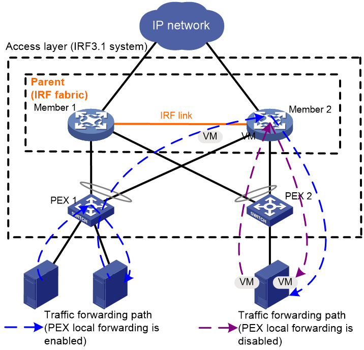
Protocols and standards
IEEE 802.1BR, Virtual Bridged Local Area Networks—Bridge Port Extension
Restrictions: Hardware compatibility with IRF 3.1
The S6820 switch series does not support this feature.
Restrictions and guidelines: IRF 3.1 configuration
Hardware compatibility with IRF 3.1
An S6800, S6860, or S6861 switch can act as a parent device or PEX.
The following switch series can be attached as PEXs to an S6800 parent fabric:
· S6800.
· S6860.
· S6861.
The following switch series can be attached as PEXs to an S6860 parent fabric:
· S6860.
· S6861.
The S6861 switch series can be attached as PEXs to an S6861 parent fabric.
PEX upstream member interface requirements
You can use only some high-speed physical interfaces on a PEX as upstream member interfaces. To identify candidate upstream member interfaces, use one of the following methods:
· Obtain information from the configuration guide for the device to be used as a PEX. Table 5, Table 6, and Table 7 show the candidate upstream member interfaces on the S6800, S6860, and S6861 switch series.
Table 5 Candidate upstream member interfaces on the S6800 switch series
|
PEX model |
Candidate upstream member interfaces |
|
S6800-54QF |
· Ten-GigabitEthernet 1/0/43 through Ten-GigabitEthernet 1/0/48. · FortyGigE 1/0/49 through FortyGigE 1/0/54. |
|
S6800-54QT |
· Ten-GigabitEthernet 1/0/43 through Ten-GigabitEthernet 1/0/48. · FortyGigE 1/0/49 through FortyGigE 1/0/54. |
|
S6800-32Q |
FortyGigE 1/0/29 through FortyGigE 1/0/32. |
|
S6800-54HF |
· Ten-GigabitEthernet 1/0/43 through Ten-GigabitEthernet 1/0/48. · HundredGigE 1/0/49 through HundredGigE 1/0/54. |
|
S6800-54HT |
· Ten-GigabitEthernet 1/0/43 through Ten-GigabitEthernet 1/0/48. · HundredGigE 1/0/49 through HundredGigE 1/0/54. |
|
S6800-2C S6800-2C-FC |
· The two QSFP+ ports on the rear panel. · The lowest numbered two QSFP+ ports on the interface module in slot 1. NOTE: To use the interface module in slot 1 to provide upstream member interfaces, make sure the two lowest numbered ports on the interface module are QSFP+ ports. Install the module before the device starts up. For the upstream port to operate correctly, do not hot swap the interface module. |
|
S6800-4C |
The two lowest numbered QSFP+ ports on the interface module in slot 1. NOTE: To use the interface module in slot 1 to provide upstream member interfaces, make sure the two lowest numbered ports on the interface module are QSFP+ ports. Install the module before the device starts up. For the upstream port to operate correctly, do not hot swap the interface module. |
Table 6 Candidate upstream member interfaces on the S6860 switch series
|
PEX model |
Candidate upstream member interfaces |
|
S6860-54HF |
· Ten-GigabitEthernet 1/0/43 through Ten-GigabitEthernet 1/0/48. · FortyGigE 1/0/49 through FortyGigE 1/0/54. |
|
S6860-54HT |
· Ten-GigabitEthernet 1/0/43 through Ten-GigabitEthernet 1/0/48. · FortyGigE 1/0/49 through FortyGigE 1/0/54. |
|
S6860-30HF |
· Ten-GigabitEthernet 1/0/19 through Ten-GigabitEthernet 1/0/24. · FortyGigE 1/0/25 through FortyGigE 1/0/30. |
Table 7 Candidate upstream member interfaces on the S6861 switch series
|
PEX model |
Candidate upstream member interfaces |
|
S6861-54HF |
· Ten-GigabitEthernet 1/0/43 through Ten-GigabitEthernet 1/0/48. · FortyGigE 1/0/49 to FortyGigE 1/0/54. |
|
S6861-54HT |
· Ten-GigabitEthernet 1/0/43 through Ten-GigabitEthernet 1/0/48. · FortyGigE 1/0/49 through FortyGigE 1/0/54. |
|
S6861-30HF |
· Ten-GigabitEthernet 1/0/19 through Ten-GigabitEthernet 1/0/24. · FortyGigE 1/0/25 through FortyGigE 1/0/30. |
· Execute the display system internal pex upstreamport command in probe view on the device to be used as a PEX when the device operates in PEX mode.
Candidate upstream member interfaces are grouped by interface type on a device. For example, Ten-GigabitEthernet 1/0/43 to Ten-GigabitEthernet 1/0/48 are in a group, and FortyGigE 1/0/49 to FortyGigE 1/0/54 are in a group. You can use all or none of the interfaces in a group as common network interfaces or upstream member interfaces. If one physical interface in a group is an upstream member interface, the remaining interfaces in the group can only act as upstream member interfaces. You cannot use them as common network interfaces. To use all interfaces in a group as common network interfaces, do not use any of the interfaces to connect the parent fabric.
To replace one group of interfaces with another group of interfaces as upstream member interfaces, you must perform the following operations:
1. Disconnect the original upstream member interfaces from the parent device.
2. Reboot the PEX.
3. Connect the new upstream member interfaces to the parent device.
Loop elimination
By default, the spanning tree feature is disabled on the ports of PEXs to prevent unnecessary topology calculations and conserve system resources. When you set up an IRF 3.1 system, you must make sure it is physically or logically loop free.
To conserve system resources, set up a physically loop-free IRF 3.1 system as shown in "Network topology." Make sure no connections exist between PEXs or between PEXs and parent devices except the cascade links.
If a port on a PEX is in a loop because of physical redundancy design, you must enable the spanning tree feature on that port.
Link aggregation restrictions and guidelines
To assign extended ports to a Layer 2 extended-link aggregation group, make sure the PEXs that contain the ports meet the following requirements:
· The PEXs belong to the same switch series.
· The PEXs are in the same PEX group.
PEX configuration management restrictions and guidelines
You must configure a PEX from the parent fabric.
To display PEX running information, use the method in "Logging in to a PEX from the parent fabric."
IRF split detection requirements
For the PEXs to quickly identify parent fabric split events, perform the following tasks on the parent fabric:
· Use the lacp system-priority command to set the system LACP priority to a value lower than 32768.
· Use the undo irf mac-address persistent command to disable IRF bridge MAC persistence. In addition, do not specify an IRF bridge MAC address by using the irf mac-address mac-address command.
Ports on a PEX cannot be used for IRF MAD of the parent fabric.
Feature compatibility and configuration restrictions with IRF 3.1
For information about the feature compatibility and configuration restrictions, see "Appendix A Feature compatibility and configuration restrictions for IRF 3.1 PEXs."
Configuration rollback restrictions
As a best practice, do not roll back the configuration if the replacement configuration file contains IRF 3.1 settings different than the running configuration. If you roll back the configuration, the system might fail to reconfigure IRF 3.1 settings as expected. For more information about the configuration rollback feature, see configuration file management in Fundamentals Configuration Guide.
IRF 3.1 tasks at a glance
To configure an IRF 3.1 system, perform the following tasks:
1. Configuring the operating mode
¡ Configuring a device as an independent device
¡ Configuring a device as a PEX
2. Setting up the parent fabric
3. Configuring PEXs on the parent fabric
b. Configuring cascade ports for PEXs
c. Assigning virtual slot numbers to PEXs
d. Connecting the PEXs to the parent fabric
4. (Optional.) Maintaining an IRF 3.1 system
¡ Enabling PEX local forwarding
¡ Enabling PEX persistent forwarding
¡ Logging in to a PEX from the parent fabric
5. Removing PEXs from an IRF 3.1 system
Planning the IRF 3.1 system setup
Consider the following items when you plan an IRF 3.1 system:
· Hardware compatibility and restrictions.
· IRF 3.1 system size.
· Parent devices and PEXs.
· Cascade ports, cascade member interfaces, upstream member interfaces, and cabling scheme.
· Virtual slot assignment for PEXs.
The plan must meet the requirements described in "Restrictions and guidelines: IRF 3.1 configuration."
For more information about hardware and cabling, see the installation guide for the device.
Configuring the operating mode
Configuring a device as an independent device
About configuring a device as an independent device
As a best practice, change the operating mode to switch and save the configuration to avoid the operating mode changing from auto to PEX due to connection errors or attacks.
Mode change from auto to switch takes effect immediately, and mode change from PEX to switch takes effect after a reboot.
Restrictions and guidelines
Perform this task on each parent device before you set up the parent fabric.
Procedure
1. Enter system view.
system-view
2. Change the operating mode to switch.
pex system-working-mode switch
By default, the device operates in auto mode. The device automatically changes to the PEX mode to join an IRF 3.1 system when it detects any LLDP packets from a parent device.
3. Save the running configuration.
save
For the switch mode to take effect after a reboot, save the running configuration.
Configuring a device as a PEX
About configuring a device as a PEX
For the device to operate as a PEX, set the device operating mode to auto or PEX.
If you set the operating mode to auto, the device automatically reboots with factory defaults when it detects LLDP packets from a parent device. After the reboot, the device operates as a PEX.
For the PEX mode to take effect, you must save the running configuration and manually reboot the device. The device starts up with the factory defaults. After the reboot, the device operates as a PEX.
Restrictions and guidelines for mode configuration
When the device operates in PEX mode, you cannot set the operating mode to auto.
Setting the operating mode to auto
1. Enter system view.
system-view
2. Set the operating mode to auto.
pex system-working-mode auto
By default, the device operates in auto mode. The device can automatically change to a PEX upon receiving LLDP packets from a parent device.
For the device to automatically change to a PEX, make sure the device does not have interfaces enabled with PEX connection capability.
3. (Optional.) Save the running configuration.
save
Save the running configuration to the next-startup configuration file for the auto mode to take effect after another reboot.
Setting the operating mode to PEX
1. Enter system view.
system-view
2. Set the operating mode to PEX.
pex system-working-mode pex
By default, the device operates in auto mode. The device can automatically change to a PEX upon receiving LLDP packets from a parent device.
3. Save the running configuration.
save
4. Return to user view.
quit
5. Reboot the device.
reboot
Setting up the parent fabric
You can use a single-member or multimember IRF fabric as the parent fabric. Before you set up the parent fabric, change the operating mode of its member devices to switch. To set up the parent fabric, use the procedure described in "Configuring an IRF fabric."
Creating a PEX group
Restrictions and guidelines
After a PEX group is created, the device automatically enables the NTP service and specifies the local clock as the reference source at stratum 2.
If you delete a PEX group, all PEXs in that group will go offline with all settings issued from the parent device removed.
Procedure
1. Enter system view.
system-view
2. Create a PEX group.
pex group group-id
3. (Optional.) Configure a description for the PEX group.
description text
By default, the description for a PEX group uses the PEX group group-id format.
Configuring cascade ports for PEXs
About cascade ports for PEXs
The cascade ports for PEXs are Layer 2 aggregate interfaces in dynamic aggregation mode. The member interfaces in each cascade port are physical interfaces that connect the parent fabric to a PEX.
The system automatically places a Layer 2 aggregate interface in dynamic aggregation mode after you enable its PEX connection capability. In addition, the system automatically configures the aggregate interface as an edge port of the spanning tree feature for the PEX to quickly come online.
Restrictions and guidelines
Make sure all physical interfaces assigned to a cascade port connect to the same PEX.
For PEXs to come online successfully, do not execute any other commands on cascade ports except for the IRF 3.1 commands, the shutdown command, and the description command. In addition, do not execute any other commands on the cascade member interfaces except for the lldp enable command.
Disabling PEX connection capability on a cascade port causes the attached PEX to go offline. When you assign a cascade port to a new PEX group, its attached PEX goes offline and then comes online again. When the PEX goes offline in either situation, all settings issued from the parent fabric are automatically removed from the PEX.
Procedure
1. Enter system view.
system-view
2. Enable LLDP globally.
lldp global enable
The default setting varies by the startup configuration.
¡ If the device starts up with the empty configuration, LLDP is disabled globally.
¡ If the device starts up with the factory defaults, LLDP is enabled globally.
3. Create a Layer 2 aggregate interface and enter Layer 2 aggregate interface view.
interface bridge-aggregation interface-number
When you create a Layer 2 aggregate interface, the system automatically creates a Layer 2 aggregation group with the same number as the aggregate interface. The aggregation group operates in static aggregation mode by default.
4. Enable PEX connection capability on the Layer 2 aggregate interface and assign it to a PEX group.
pex-capability enable group group-id
By default, an aggregate interface cannot connect PEXs.
5. Return to system view.
quit
6. Enter Layer 2 Ethernet interface view or Layer 2 Ethernet interface range view.
¡ Enter interface view.
interface interface-type interface-number
¡ Enter interface range view.
interface range { interface-type interface-number [ to interface-type interface-number ] } &<1-24>
To assign one port to the aggregation group, enter Ethernet interface view.
To assign a range of ports to the aggregation group, enter interface range view.
7. Assign Layer 2 Ethernet ports to the aggregation group.
port link-aggregation group group-id
All physical interfaces assigned to the aggregate interface must connect to the same PEX
8. Enable LLDP on the ports.
lldp enable
By default, LLDP is enabled on a port.
Assigning virtual slot numbers to PEXs
Restrictions and guidelines
When you remove or change the virtual PEX slot number of an online PEX, make sure you understand its impact on that PEX:
· If you remove the virtual slot number, the PEX goes offline. All settings issued from the parent fabric are cleared on the PEX.
· If you change the virtual slot number, the PEX goes offline and then comes online with the new virtual slot. All settings issued from the parent fabric are cleared from the PEX after the PEX goes offline.
Procedure
1. Enter system view.
system-view
2. Enter Layer 2 aggregate interface view.
interface bridge-aggregation interface-number
3. Assign a virtual slot number to the PEX.
pex associate slot slot-number
By default, no virtual slot number is assigned to a PEX.
Connecting the PEXs to the parent fabric
Connect the upstream member interfaces on a PEX to the cascade member interfaces of the cascade port on the parent fabric.
To identify candidate upstream member interfaces, see "PEX upstream member interface requirements."
For information about connection restrictions and guidelines, see "Network topology."
Enabling PEX local forwarding
About PEX local forwarding
This feature enables a PEX to perform local forwarding for Layer 2 unicast packets with known MAC addresses. The PEX reports other packets to the parent fabric for processing.
If PEX local forwarding is disabled for a PEX, the PEX sends any incoming traffic to the parent fabric. The parent fabric makes forwarding decisions and sends the traffic to the outgoing interfaces.
When you enable or disable PEX local forwarding on a cascade port, the PEX will go offline and then come online again.
Procedure
1. Enter system view.
system-view
2. Enter Layer 2 aggregate interface view of a cascade port.
interface bridge-aggregation interface-number
3. Enable PEX local forwarding.
pex local-forwarding
By default, PEX local forwarding is disabled.
Enabling PEX persistent forwarding
About PEX persistent forwarding
If PEX persistent forwarding is enabled for a PEX, the system will not clear the running data or shut down the network interfaces on the PEX after the PEX goes offline. The PEX can still perform local forwarding.
If PEX persistent forwarding is disabled for a PEX, the system clears the running data and shuts down all network interfaces on the PEX after the PEX goes offline. However, the system does not shut down the upstream member interfaces on the PEX. The PEX will attempt to recover the connection with the parent fabric by sending protocol control packets out of the upstream member interfaces.
Prerequisites
For PEX persistent forwarding to take effect on a PEX, you must enable PEX local forwarding for that PEX.
Procedure
1. Enter system view.
system-view
2. Enter Layer 2 aggregate interface view of a cascade port.
interface bridge-aggregation interface-number
3. Enable PEX persistent forwarding.
pex persistent-forwarding
By default, PEX persistent forwarding is disabled.
Logging in to a PEX from the parent fabric
About logging in to a PEX from the parent fabric
After you log in to a PEX, you can execute the following commands:
· The display commands.
· File system management commands. To obtain information about the access permissions to the commands, use the display role feature name filesystem command in RBAC. For more information about the file system management and RBAC commands, see Fundamentals Command Reference.
Procedure
1. Enter system view.
system-view
2. Log in to a PEX.
switchto pex slot slot-number
Removing PEXs from an IRF 3.1 system
About removing PEXs from an IRF 3.1 system
To temporarily remove a PEX from an IRF 3.1 system, disconnect the PEX links between the PEX and the parent fabric or power off the PEX.
To remove a PEX from an IRF 3.1 system and use it as an independent device, log in to the PEX through the console port and change the operating mode to switch.
Procedure
1. Enter system view.
system-view
2. Change the PEX to switch mode.
pex system-working-mode switch
By default, the device operates in auto mode.
3. Save the running configuration.
save
The device will operate in the mode set in the startup configuration after a reboot if you do not save the running configuration.
4. Return to user view.
quit
5. Reboot the PEX for the mode change to take effect.
reboot
Display and maintenance commands for IRF 3.1
Execute display commands in any view.
|
Task |
Command |
|
Display device information. |
display device |
|
Display electronic label information for the device. |
display device manuinfo |
|
Display information about PEX state and PE CSP statistics for a cascade port or for all cascade ports. |
display pex interface [ interface-name ] [ brief ] |
|
Display system operating mode information in an IRF 3.1 system. |
display pex system-working-mode |
|
Display PEX topology information. |
display pex topology |
|
Display system version information. |
display version |
|
|
NOTE: For information about the display device, display device manuinfo, and display version commands, see Fundamentals Command Reference. |
IRF 3.1 configuration examples
Example: Configuring an IRF 3.1 system
Network configuration
As shown in Figure 31, set up an IRF 3.1 system that contains a two-chassis parent fabric and one tier of PEXs. The parent fabric contains two S6800-54QT switches and the two PEXs are S6800-54QT switches.
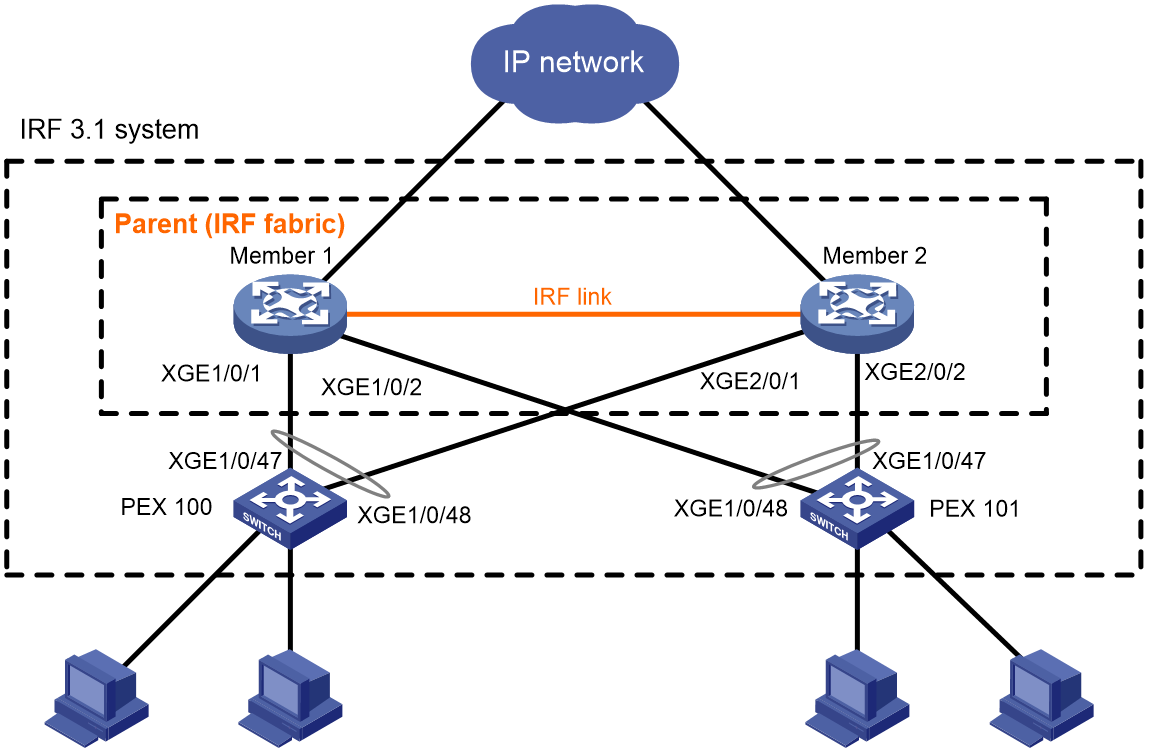
Setting up the parent fabric
# Log in to Member 1 and Member 2, and change the operating mode of Member 1 and Member 2 to switch, respectively.
<Sysname> system-view
[Sysname] pex system-working-mode switch
# Set up a two-chassis IRF fabric with Member 1 and Member 2, as described in "Configuring an IRF fabric." (Details not shown.)
Configuring cascade ports for PEXs on the parent fabric
# Enter the system view.
<Sysname> system-view
# Enable LLDP globally.
[Sysname] lldp global enable
# Create PEX group 1.
[Sysname] pex group 1
[Sysname-pex-group-1] quit
# Create Layer 2 aggregate interface Bridge-Aggregation 100. The aggregate interface will act as the cascade port to the PEX in slot 100.
[Sysname] interface bridge-aggregation 100
# Enable PEX connection capability on Bridge-Aggregation 100 and assign Bridge-Aggregation 100 to PEX group 1.
[Sysname-Bridge-Aggregation100] pex-capability enable group 1
The aggregate interface was automatically set to dynamic aggregation mode and configured as an STP edge port.
# Assign virtual slot number 100 to the PEX.
[Sysname-Bridge-Aggregation100] pex associate slot 100
[Sysname-Bridge-Aggregation100] quit
# Enable LLDP on Ten-GigabitEthernet 1/0/1 and Ten-GigabitEthernet 2/0/1 in interface range view, and assign the ports to aggregation group 100. The ports will act as the cascade member interfaces.
[Sysname] interface range ten-gigabitethernet 1/0/1 ten-gigabitethernet 2/0/1
[Sysname-if-range] lldp enable
[Sysname-if-range] port link-aggregation group 100
[Sysname-if-range] quit
# Create Layer 2 aggregate interface Bridge-Aggregation 101. The aggregate interface will act as the cascade port to the PEX in slot 101.
[Sysname] interface bridge-aggregation 101
# Enable PEX connection capability on Bridge-Aggregation 101 and assign the interface to PEX group 1.
[Sysname] interface bridge-aggregation 101
[Sysname-Bridge-Aggregation101] pex-capability enable group 1
The aggregate interface was automatically set to dynamic aggregation mode and configured as an STP edge port.
# Assign virtual slot number 101 to the PEX.
[Sysname-Bridge-Aggregation101] pex associate slot 101
[Sysname-Bridge-Aggregation101] quit
# Enable LLDP on Ten-GigabitEthernet 1/0/2 and Ten-GigabitEthernet 2/0/2 in interface range view, and assign the ports to aggregation group 101. The ports will act as the cascade member interfaces.
[Sysname] interface range ten-gigabitethernet 1/0/2 ten-gigabitethernet 2/0/2
[Sysname-if-range] lldp enable
[Sysname-if-range] port link-aggregation group 101
[Sysname-if-range] quit
Configuring PEXs
Configure the devices to be used as PEXs to operate in auto or PEX mode. This section only describes configuration on PEX 100. Configure PEX 101 in the same way PEX 100 is configured.
· Configure PEX 100 to operate in auto mode:
# Change the operating mode to auto. This task is optional. By default, the operating mode is auto.
<Sysname> system-view
[Sysname] pex system-working-mode auto
# Save the running configuration.
[Sysname] save
The current configuration will be written to the device. Are you sure? [Y/N]:y
Please input the file name(*.cfg)[flash:/startup.cfg]
(To leave the existing filename unchanged, press the enter key):
flash:/startup.cfg exists, overwrite? [Y/N]:y
Validating file. Please wait...
Saved the current configuration to mainboard device successfully.
# Select upstream member interfaces. In this example, Ten-GigabitEthernet 1/0/47 and Ten-GigabitEthernet 1/0/48 are used. For information about candidate upstream member interfaces, see the manuals for the PEX. (Details not shown.)
# Connect the upstream member interfaces on PEX 100 and the cascade member interfaces on the parent fabric. (Details not shown.)
· Configure PEX 100 to operate in PEX mode:
# Change the operating mode to PEX.
<Sysname> system-view
[Sysname] pex system-working-mode pex
# Save the running configuration.
[Sysname] save
[Sysname] quit
# Reboot PEX 100.
<Sysname> reboot
# Display candidate upstream member interfaces.
<Sysname> system-view
[Sysname] probe
[Sysname-probe] display system internal pex upstreamport
IfIndex Interface LldpPktRcvd Priority PeerPort-PE-CSP-Addr
43 XGE1/0/43 No 255 ffff-ffff-ffff
44 XGE1/0/44 No 255 ffff-ffff-ffff
45 XGE1/0/45 No 255 ffff-ffff-ffff
46 XGE1/0/46 No 255 ffff-ffff-ffff
47 XGE1/0/47 No 255 ffff-ffff-ffff
48 XGE1/0/48 No 255 ffff-ffff-ffff
49 FGE1/0/49 No 255 ffff-ffff-ffff
50 FGE1/0/50 No 255 ffff-ffff-ffff
51 FGE1/0/51 No 255 ffff-ffff-ffff
52 FGE1/0/52 No 255 ffff-ffff-ffff
53 FGE1/0/53 No 255 ffff-ffff-ffff
54 FGE1/0/54 No 255 ffff-ffff-ffff
# Connect PEX 100 to the parent fabric, as shown in Figure 31. In this example, Ten-GigabitEthernet 1/0/47 and Ten-GigabitEthernet 1/0/48 are used as upstream member interfaces. (Details not shown.)
Verifying the configuration
# Display device information on the parent fabric. Verify that the output contains information about both the parent fabric and the PEXs.
<Sysname> display device
Slot Type State Subslot Soft Ver Patch Ver
1 S6800-54QT Master 0 2702003 None
PEX in virtual slot : 100
Slot Type State Subslot Soft Ver Patch Ver
1 S6800-54QT Master 0 2702003 None
PEX in virtual slot : 101
Slot Type State Subslot Soft Ver Patch Ver
1 S6800-54QT Master 0 2702003 None
# Display PEX topology information.
<Sysname> display pex topology
Group 1
Tier 1
PEX 100 -----> Parent
PEX 101 -----> Parent
Appendix A Feature compatibility and configuration restrictions for IRF 3.1 PEXs
Table 8 shows all features that can run on PEXs and their configuration restrictions and guidelines. This table does not list a feature if it cannot run on the PEXs or if it is not designed to run on the PEXs.
Table 8 Features that can run on PEXs and their restrictions and guidelines
|
Feature name |
Restrictions and guidelines on PEXs |
|
Fundamentals features |
|
|
CLI |
In an IRF 3.1 system, you can only access the CLI of the master to configure PEXs. |
|
RBAC |
User roles and access permissions are configured on the parent fabric. For more information, see RBAC in the manual for the parent fabric. |
|
Login management |
As a best practice, log in to the IRF 3.1 system from a port on the parent fabric instead of a port on a PEX. |
|
FTP and TFTP |
You can only transfer files to the parent fabric. |
|
File system management |
The file system of a PEX is inaccessible from the CLI of the master. |
|
Configuration file management |
The running configuration is automatically synchronized from the master to the PEXs. |
|
Software upgrade |
You can use the boot-loader pex command to specify startup images for the PEXs. If the flash memory of a PEX does not have sufficient storage space, you can log in to the PEX through the console port on the PEX to delete unused files. |
|
Device management |
You can perform the following tasks to configure and manage the PEXs: · Specify the preferred airflow direction. · Configure parity error alarm for entries on forwarding chips. · Display startup software image upgrade records. · Configure the temperature alarm thresholds and display device temperature information. · Monitor CPU usage. · Set memory alarm thresholds. · Reboot PEXs (rebooting a subcard is not supported). |
|
Tcl |
PEXs are configurable with Tcl. |
|
Python |
PEXs are configurable with Python. |
|
Layer 2—LAN Switching features |
|
|
Ethernet interfaces |
You can perform the following tasks to configure Ethernet interfaces on the PEXs: · Configure Layer 2 Ethernet interfaces and basic features. · Set the MDIX mode of an Ethernet interface. · Split a 40-GE interface and combine 10-GE breakout interfaces. · Forcibly bring up a fiber port. · Set the statistics polling interval for an Ethernet interface. |
|
Loopback, null, and inloopback interfaces |
N/A |
|
Bulk configuring interfaces (interface range) |
N/A |
|
MAC address table |
PEXs support manual configuration of static, dynamic, multiport unicast, and blackhole MAC address entries. |
|
Ethernet link aggregation |
PEXs support the following Ethernet link aggregation features on their ports: · Assign the ports to dynamic and static Layer 2 aggregation groups. · Set the short LACP timeout interval (3 seconds). |
|
Spanning tree |
PEXs support all spanning tree features except disabling spanning tree on a port. |
|
VLAN |
You can assign ports on the PEXs to port-based VLANs. |
|
LLDP |
PEXs support all LLDP features except the following features: · Configure LLDP on Layer 3 Ethernet interfaces. · Advertisement of the management address TLV. |
|
Layer 3—IP Services features |
|
|
ARP |
PEXs support all ARP features except the following features: · ARP direct route advertisement. · Configure an interface as a customer-side port by using the arp mode uni command. |
|
IP addressing |
N/A |
|
DHCP |
N/A |
|
IP forwarding basics |
N/A |
|
Fast forwarding |
N/A |
|
IP performance optimization |
N/A |
|
IPv6 basics |
N/A |
|
DHCPv6 |
N/A |
|
IPv6 fast forwarding |
N/A |
|
Layer 3—IP Routing features |
|
|
Basic IP routing |
N/A |
|
Static routing |
PEXs support all static routing features except BFD-related features. |
|
RIP |
PEXs support all RIP features except the following features: · Set the maximum number of RIP ECMP routes. · BFD-related features. |
|
OSPF |
PEXs support all OSPF features except the ospf network-type p2mp command. |
|
BGP |
N/A |
|
IPv6 static routing |
PEXs support all IPv6 static routing features except BFD-related features. |
|
RIPng |
PEXs support all RIPng features except the following features: |
|
OSPFv3 |
N/A |
|
Routing policy |
N/A |
|
ACL and QoS features |
|
|
ACL |
N/A |
|
QoS |
N/A |
|
Time range |
N/A |
|
QCN |
N/A |
|
Security features |
|
|
ARP attack protection |
PEXs support the following features: · ARP scanning and fixed ARP. |
|
Crypto engine |
N/A |
|
High Availability features |
|
|
Process placement |
The processes on PEXs are inaccessible from the CLI of the master. |
|
Network Management and Monitoring features |
|
|
System maintenance and debugging |
N/A |
|
NTP |
N/A |
|
SNMP |
PEXs support all SNMP features except the following features: · SNMP logging. · Set the notification queue size. · SNMP notifications for features not supported on PEXs. |
|
NETCONF |
N/A |
|
EAA |
N/A |
|
Process monitoring and maintenance |
The processes on PEXs are inaccessible from the CLI of the master. |
|
Information center |
PEXs support all information center features except outputting logs to the log buffer. |
|
VCF fabric |
N/A |
|
Puppet |
N/A |
|
Chef |
N/A |
|
TRILL features |
|
|
TRILL port |
The link types of the TRILL ports on PEXs can only be access. |
