- Table of Contents
-
- 01-Fundamentals Configuration Guide
- 00-Preface
- 01-CLI configuration
- 02-RBAC configuration
- 03-Login management configuration
- 04-FTP and TFTP configuration
- 05-File system management configuration
- 06-Configuration file management configuration
- 07-Software upgrade configuration
- 08-ISSU configuration
- 09-Emergency shell configuration
- 10-Device management configuration
- 11-Tcl configuration
- 12-Python configuration
- 13-License management
- 14-Preprovisioning feature configuration
- 15-Automatic configuration
- Related Documents
-
| Title | Size | Download |
|---|---|---|
| 15-Automatic configuration | 206.60 KB |
Contents
Automatic configuration task list
Preparing the files for automatic configuration
Configuring the DHCP server when an HTTP file server is used
Configuring the DHCP server when a TFTP file server is used
Preparing the interface used for automatic configuration
Starting and completing automatic configuration
Automatic configuration examples
Automatic configuration using TFTP server
Automatic configuration using HTTP server and Tcl script
Automatic configuration using HTTP server and Python script
Using automatic configuration
Overview
When the device starts up without a valid next-startup configuration file, the device searches the root directory of its default file system for the autocfg.py, autocfg.tcl, and autocfg.cfg files. If any one of the files exists, the device loads the file. If none of the files exists, the device uses the automatic configuration feature to obtain a set of configuration settings. This feature simplifies network configuration and maintenance.
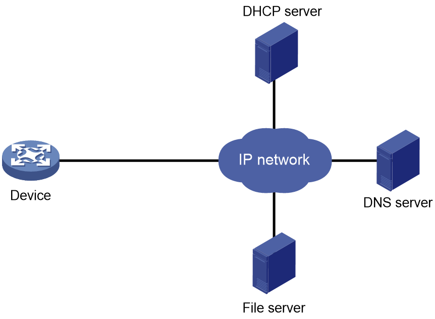
Automatic configuration can be implemented by using a set of servers, including a DHCP server and a file server (HTTP or TFTP server), as shown in Figure 1. A DNS server might also be required.
Automatic configuration applies to scenarios that have the following characteristics:
· A number of devices need to be configured.
· The devices to be configured are widely distributed.
· The configuration workload on individual devices is heavy.
Figure 1 Automatic configuration network diagram
Automatic configuration task list
|
Tasks at a glance |
|
(Required.) Configuring the file server |
|
(Required.) Preparing the files for automatic configuration |
|
(Required.) Configuring the DHCP server |
|
(Optional.) Configuring the DNS server |
|
(Optional.) Configuring the gateway |
|
(Required.) Preparing the interface used for automatic configuration |
|
(Required.) Starting and completing automatic configuration |
Configuring the file server
For devices to obtain configuration information from a TFTP server, start TFTP service on the file server.
For devices to obtain configuration information from an HTTP server, start HTTP service on the file server.
Preparing the files for automatic configuration
The device can use a script file or configuration file for automatic configuration.
· For devices to use configuration files for automatic configuration, you must create and save the configuration files to the file server as described in "Configuration files." If you do not configure the DHCP server to assign configuration file names, you must also create a host name file on the TFTP server.
· For devices to use script files for automatic configuration, you must create and save the script files to the file server as described in "Script files."
Host name file
The host name file contains host name-IP address mappings and must be named network.cfg.
All mapping entries in the host name file must use the ip host host-name ip-address format. Each mapping entry must reside on a separate line. For example:
ip host host1 101.101.101.101
ip host host2 101.101.101.102
ip host client1 101.101.101.103
ip host client2 101.101.101.104
Configuration files
To prepare configuration files:
· For devices that require different configurations, perform the following tasks:
¡ Determine the name for each device's configuration file.
The configuration file names must use the extension .cfg. For simple file name identification, use configuration file names that do not contain spaces.
¡ Use the file names to save the configuration files for the devices to the file server.
· For devices that share all or some configurations, save the common configurations to a .cfg file on the file server.
· If a TFTP file server is used, you can save a default configuration file named device.cfg on the server. This file contains only common configurations that devices use to start up. This file is assigned to a device only when the device does not have other configuration files to use.
During the automatic configuration process, a device first tries to obtain a configuration file dedicated for it. If no dedicated configuration file is found, the device tries to obtain the common configuration file. If no common configuration file is found when a TFTP file server is used, the device obtains and uses the default configuration file.
Script files
Script files can be used for automatic software upgrade and automatic configuration. The device supports Python scripts (.py files) and Tcl scripts (.tcl files). For more information about Python and Tcl scripts, see "Using Python" and "Using Tcl."
Make sure all commands in the Tcl scripts are supported, correctly spelled, and are executed in the correct views. If a faulty command cannot be executed and causes the automatic configuration process to be aborted.
To prepare script files:
· For devices that share all or some configurations, create a script file that contains the common configurations.
· For the other devices, create a separate script file for each of them.
Configuring the DHCP server
The DHCP server assigns the following items to devices that need to be automatically configured:
· IP addresses.
· Paths of the configuration files or scripts.
Configuration guidelines
When you configure the DHCP server, follow these guidelines:
· For devices for which you have prepared different configuration files, perform the following tasks for each of the devices on the DHCP server:
¡ Create a DHCP address pool.
¡ Configure a static address binding.
¡ Specify a configuration file or script file.
Because an address pool can use only one configuration file, you can specify only one static address binding for an address pool.
· For devices for which you have prepared the same configuration file, use either of the following methods:
¡ Method 1:
- Create a DHCP address pool for the devices.
- Configure a static address binding for each of the devices in the address pool.
- Specify the configuration file for the devices.
¡ Method 2:
- Create a DHCP address pool for the devices.
- Specify the subnet for dynamic allocation.
- Specify the TFTP server.
- Specify the configuration file for the devices.
· If all devices on a subnet share the same configuration file or script file, perform the following tasks on the DHCP server:
¡ Configure dynamic address allocation.
¡ Specify the configuration file or script file for the devices.
The file can contain only the common settings for the devices. You can provide a method for the device administrators to change the configurations after their devices start up.
Configuring the DHCP server when an HTTP file server is used
|
Step |
Command |
Remarks |
|
1. Enter system view. |
system-view |
N/A |
|
2. Enable DHCP. |
dhcp enable |
By default, DHCP is disabled. |
|
3. Create a DHCP address pool and enter its view. |
dhcp server ip-pool pool-name |
By default, no DHCP address pool is created. |
|
4. Configure the address pool. |
· (Method 1.) Specify the primary subnet for the
address pool: · (Method 2.) Configure a static binding: |
Use either or both methods. By default, no primary subnet or static binding is configured. You can add multiple static bindings. One IP address can be bound to only one client. To change the binding for a DHCP client, you must remove the binding and reconfigure a binding. |
|
5. Specify the URL of the configuration file or script file. |
bootfile-name url |
By default, no configuration or script file URL is specified. |
Configuring the DHCP server when a TFTP file server is used
|
Step |
Command |
Remarks |
|
1. Enter system view. |
system-view |
N/A |
|
2. Enable DHCP. |
dhcp enable |
By default, DHCP is disabled. |
|
3. Create a DHCP address pool and enter its view. |
dhcp server ip-pool pool-name |
By default, no DHCP address pool is created. |
|
4. Configure the address pool. |
· (Method 1.) Specify the primary subnet for the
address pool: · (Method 2.) Configure a static binding: |
Use either or both methods. By default, no primary subnet or static binding is configured. You can add multiple static bindings. One IP address can be bound to only one client. To change the binding for a DHCP client, you must remove the binding and reconfigure a binding. |
|
5. Specify a TFTP server. |
· (Method 1.) Specify the IP address of the TFTP
server: · (Method 2.) Specify the name of the TFTP
server: |
Use either or both methods. By default, no TFTP server is specified. If you specify a TFTP server by its name, a DNS server is required on the network. |
|
6. Specify the configuration file name or the script file name. |
bootfile-name bootfile-name |
By default, no configuration file name or script file name is specified. |
Configuring the DNS server
A DNS server is required in the following situations:
· The TFTP server does not have a host name file. However, devices need to perform the following operations:
¡ Use their IP addresses to obtain their host names.
¡ Obtain configuration files named in the host name.cfg format from the TFTP server.
· The DHCP server assigns the TFTP server domain name through the DHCP reply message. Devices must use the domain name to obtain the IP address of the TFTP server.
Configuring the gateway
If the devices to be automatically configured and the servers for automatic configuration reside in different network segments, you must perform the following tasks:
· Deploy a gateway and make sure the devices can communicate with the servers.
· Configure the DHCP relay agent feature on the gateway.
· Configure the UDP helper feature on the gateway.
When a device sends a request through a broadcast packet to the file server, the UDP helper changes the broadcast packet to a unicast packet and forwards the unicast packet to the file server. For more information about UDP helper, see Layer 3—IP Services Configuration Guide.
Preparing the interface used for automatic configuration
The device uses the following steps to select the interface for automatic configuration:
1. Identifies the status of the management Ethernet interface at Layer 2. If the status is up, the device uses the management Ethernet interface.
2. Identifies the status of Layer 2 Ethernet interfaces. If one or more Layer 2 Ethernet interfaces are in up state, the device uses the VLAN interface of the default VLAN.
3. Sorts all Layer 3 Ethernet interfaces in up state first in lexicographical order of interface types and then in ascending order of interface numbers. Uses the interface with the smallest interface number among the interfaces of the first interface type.
4. If no Layer 3 Ethernet interfaces are in up state, the device waits 30 seconds and goes to step 1 to try again.
For fast automatic device configuration, connect only the management Ethernet interface on each device to the network.
Starting and completing automatic configuration
1. Power on the devices to be automatically configured.
If a device does not find a next-start configuration file locally, it starts the automatic configuration process to obtain a configuration file. If one attempt fails, the device waits 30 seconds and then automatically starts the process again. To stop the process, press Ctrl+C or Ctrl+D.
After obtaining a configuration file, the device automatically executes the configuration file.
2. Use the save command to save the running configuration.
The device does not save the obtained configuration file locally. If you do not save the running configuration, the device must use the automatic configuration feature again after a reboot.
For more information about the save command, see Fundamentals Command Reference.
Automatic configuration examples
Automatic configuration using TFTP server
Network requirements
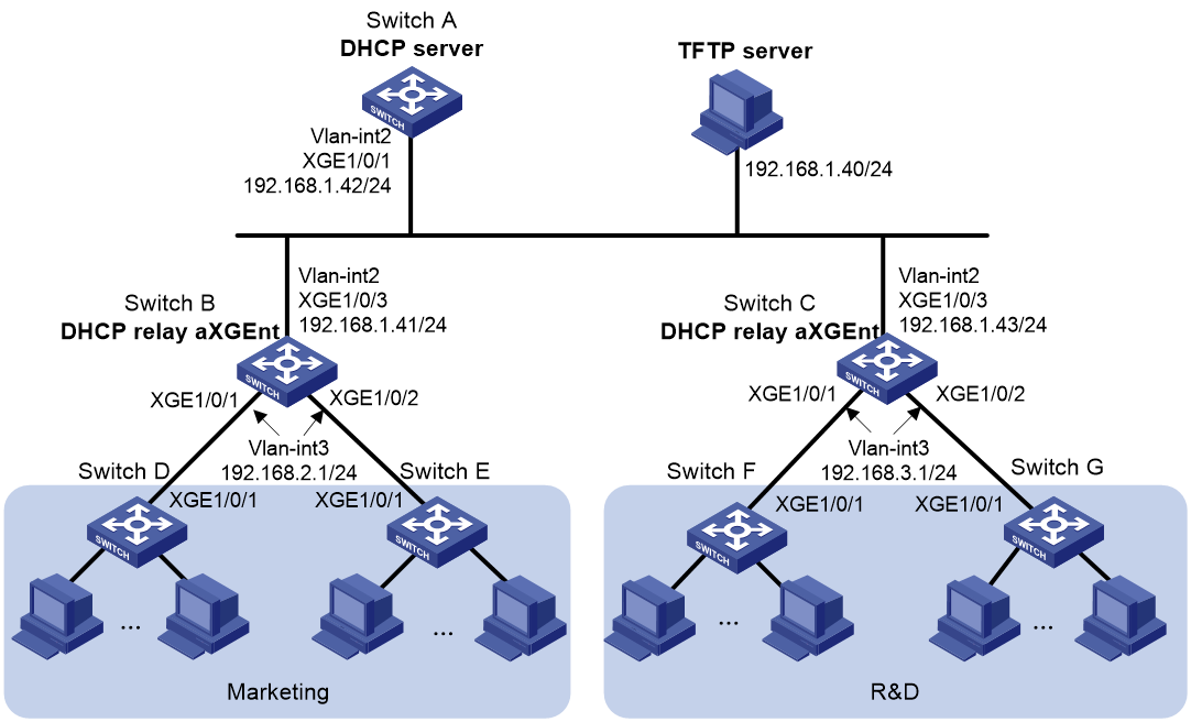
As shown in Figure 2, two departments of a company are connected to the network through gateways (Switch B and Switch C). Access devices Switch D, Switch E, Switch F, and Switch G do not have a configuration file.
Configure the servers and gateways so the access devices can obtain a configuration file to complete the following configuration tasks:
· Enable administrators of access devices to Telnet to and manage their respective access devices.
· Require administrators to enter their respective usernames and passwords at login.
Configuration procedure
1. Configure the DHCP server:
# Create a VLAN interface and assign an IP address to the interface.
<SwitchA> system-view
[SwitchA] vlan 2
[SwitchA-vlan2] port ten-gigabitethernet 1/0/1
[SwitchA-vlan2] quit
[SwitchA] interface vlan-interface 2
[SwitchA-Vlan-interface2] ip address 192.168.1.42 24
[SwitchA-Vlan-interface2] quit
# Enable DHCP.
[SwitchA] dhcp enable
# Enable the DHCP server on VLAN-interface 2.
[SwitchA] interface vlan-interface 2
[SwitchA-Vlan-interface2] dhcp select server
[SwitchA-Vlan-interface2] quit
# Configure address pool market to assign IP addresses on the 192.168.2.0/24 subnet to clients in the Marketing department. Specify the TFTP server, gateway, and configuration file name for the clients.
[SwitchA] dhcp server ip-pool market
[SwitchA-dhcp-pool-market] network 192.168.2.0 24
[SwitchA-dhcp-pool-market] tftp-server ip-address 192.168.1.40
[SwitchA-dhcp-pool-market] gateway-list 192.168.2.1
[SwitchA-dhcp-pool-market] bootfile-name market.cfg
[SwitchA-dhcp-pool-market] quit
# Configure address pool rd to assign IP addresses on the 192.168.3.0/24 subnet to clients in the R&D department. Specify the TFTP server, gateway, and configuration file name for the clients.
[SwitchA] dhcp server ip-pool rd
[SwitchA-dhcp-pool-rd] network 192.168.3.0 24
[SwitchA-dhcp-pool-rd] tftp-server ip-address 192.168.1.40
[SwitchA-dhcp-pool-rd] gateway-list 192.168.3.1
[SwitchA-dhcp-pool-rd] bootfile-name rd.cfg
[SwitchA-dhcp-pool-rd] quit
# Configure static routes to the DHCP relay agents.
[SwitchA] ip route-static 192.168.2.0 24 192.168.1.41
[SwitchA] ip route-static 192.168.3.0 24 192.168.1.43
[SwitchA] quit
2. Configure the gateway Switch B:
# Create VLAN interfaces and assign IP addresses to the interfaces.
<SwitchB> system-view
[SwitchB] vlan 2
[SwitchB-vlan2] port ten-gigabitethernet 1/0/3
[SwitchB-vlan2] quit
[SwitchB] interface vlan-interface 2
[SwitchB-Vlan-interface2] ip address 192.168.1.41 24
[SwitchB-Vlan-interface2] quit
[SwitchB] vlan 3
[SwitchB-vlan3] port ten-gigabitethernet 1/0/1
[SwitchB-vlan3] port ten-gigabitethernet 1/0/2
[SwitchB-vlan3] quit
[SwitchB] interface vlan-interface 3
[SwitchB-Vlan-interface3] ip address 192.168.2.1 24
[SwitchB-Vlan-interface3] quit
# Enable DHCP.
[SwitchB] dhcp enable
# Enable the DHCP relay agent on VLAN-interface 3.
[SwitchB] interface vlan-interface 3
[SwitchB-Vlan-interface3] dhcp select relay
# Specify the DHCP server address.
[SwitchB-Vlan-interface3] dhcp relay server-address 192.168.1.42
3. Configure the gateway Switch C:
# Create VLAN interfaces and assign IP addresses to the interfaces.
<SwitchC> system-view
[SwitchC] vlan 2
[SwitchC-vlan2] port ten-gigabitethernet 1/0/3
[SwitchC-vlan2] quit
[SwitchC] interface vlan-interface 2
[SwitchC-Vlan-interface2] ip address 192.168.1.43 24
[SwitchC-Vlan-interface2] quit
[SwitchC] vlan 3
[SwitchC-vlan3] port ten-gigabitethernet 1/0/1
[SwitchC-vlan3] port ten-gigabitethernet 1/0/2
[SwitchC-vlan3] quit
[SwitchC] interface vlan-interface 3
[SwitchC-Vlan-interface3] ip address 192.168.3.1 24
[SwitchC-Vlan-interface3] quit
# Enable DHCP.
[SwitchC] dhcp enable
# Enable the DHCP relay agent on VLAN-interface 3.
[SwitchC] interface vlan-interface 3
[SwitchC-Vlan-interface3] dhcp select relay
# Specify the DHCP server address.
[SwitchC-Vlan-interface3] dhcp relay server-address 192.168.1.42
4. Configure the TFTP server:
# On the TFTP server, create a configuration file named market.cfg.
#
sysname Market
#
telnet server enable
#
vlan 3
#
local-user market
password simple market
service-type telnet
quit
#
interface Vlan-interface3
ip address dhcp-alloc
quit
#
interface ten-gigabitethernet 1/0/1
port access vlan 3
quit
#
user-interface vty 0 63
authentication-mode scheme
user-role network-admin
#
return
# On the TFTP server, create a configuration file named rd.cfg.
#
sysname RD
#
telnet server enable
#
vlan 3
#
local-user rd
password simple rd
service-type telnet
quit
#
interface Vlan-interface3
ip address dhcp-alloc
quit
#
interface ten-gigabitethernet 1/0/1
port access vlan 3
quit
#
user-interface vty 0 63
authentication-mode scheme
user-role network-admin
#
return
# Start TFTP service software, and specify the folder where the two configuration files reside as the working directory. (Details not shown.)
# Verify that the TFTP server and DHCP relay agents can reach each other. (Details not shown.)
Verifying the configuration
1. Power on Switch D, Switch E, Switch F, and Switch G.
2. After the access devices start up, display assigned IP addresses on Switch A.
<SwitchA> display dhcp server ip-in-use
IP address Client-identifier/ Lease expiration Type
Hardware address
192.168.2.2 3030-3066-2e65-3233- May 6 05:21:25 2013 Auto(C)
642e-3561-6633-2d56-
6c61-6e2d-696e-7465-
7266-6163-6533
192.168.2.3 3030-3066-2e65-3230- May 6 05:22:50 2013 Auto(C)
302e-3232-3033-2d56-
6c61-6e2d-696e-7465-
7266-6163-6533
192.168.3.2 3030-6530-2e66-6330- May 6 05:23:15 2013 Auto(C)
302e-3335-3131-2d56-
6c61-6e2d-696e-7465-
7266-6163-6531
192.168.3.3 3030-6530-2e66-6330- May 6 05:24:10 2013 Auto(C)
302e-3335-3135-2d56-
6c61-6e2d-696e-7465-
7266-6163-6532
3. Telnet to 192.168.2.2 from Switch A.
<SwitchA> telnet 192.168.2.2
4. Enter username market and password market as prompted. (Details not shown.)
You are logged in to Switch D or Switch E.
Automatic configuration using HTTP server and Tcl script
Network requirements
As shown in Figure 3, Switch A does not have a configuration file.
Configure the servers so Switch A can obtain a Tcl script to complete the following configuration tasks:
· Enable the administrator to Telnet to Switch A to manage Switch A.
· Require the administrator to enter the correct username and password at login.

Configuration procedure
1. Configure the DHCP server:
# Enable DHCP.
<DeviceA> system-view
[DeviceA] dhcp enable
# Configure address pool 1 to assign IP addresses on the 192.168.1.0/24 subnet to clients.
[DeviceA] dhcp server ip-pool 1
[DeviceA-dhcp-pool-1] network 192.168.1.0 24
# Specify the URL of the script file for the clients.
[DeviceA-dhcp-pool-1] bootfile-name http://192.168.1.40/device.tcl
2. Configure the HTTP server:
# Create a configuration file named device.tcl on the HTTP server.
return
system-view
telnet server enable
local-user user
password simple abcabc
service-type telnet
quit
user-interface vty 0 63
authentication-mode scheme
user-role network-admin
quit
interface Vlan-interface1
port link-mode route
ip address dhcp-alloc
return
# Start HTTP service software and enable HTTP service. (Details not shown.)
Verifying the configuration
1. Power on Switch A.
2. After Switch A starts up, display assigned IP addresses on Device A.
<DeviceA> display dhcp server ip-in-use
IP address Client identifier/ Lease expiration Type
Hardware address
192.168.1.2 0030-3030-632e-3239- Dec 12 17:41:15 2013 Auto(C)
3035-2e36-3736-622d-
4574-6830-2f30-2f32
3. Telnet to 192.168.1.2 from Device A.
<DeviceA> telnet 192.168.1.2
4. Enter username user and password abcabc as prompted. (Details not shown.)
You are logged in to Switch A.
Automatic configuration using HTTP server and Python script
Network requirements
As shown in Figure 4, Switch A does not have a configuration file.
Configure the servers so Switch A can obtain a Python script to complete the following configuration tasks:
· Enable the administrator to Telnet to Switch A to manage Switch A.
· Require the administrator to enter the correct username and password at login.

Configuration procedure
1. Configure the DHCP server:
# Enable DHCP.
<DeviceA> system-view
[DeviceA] dhcp enable
# Configure address pool 1 to assign IP addresses on the 192.168.1.0/24 subnet to clients.
[DeviceA] dhcp server ip-pool 1
[DeviceA-dhcp-pool-1] network 192.168.1.0 24
# Specify the URL of the script file for the clients.
[DeviceA-dhcp-pool-1] bootfile-name http://192.168.1.40/device.py
2. Configure the HTTP server:
# Create a configuration file named device.py on the HTTP server.
#!usr/bin/python
import comware
comware.CLI(‘system-view ;telnet server enable ;local-user user ;password simple abcabc ;service-type telnet ;quit ;user-interface vty 0 4 ;authentication-mode scheme ;user-role network-admin ;quit ;interface Vlan-interface1 ;port link-mode route ;ip address dhcp-alloc ;return’)
# Start HTTP service software and enable HTTP service. (Details not shown.)
Verifying the configuration
1. Power on Switch A.
2. After Switch A starts up, display assigned IP addresses on Device A.
<DeviceA> display dhcp server ip-in-use
IP address Client identifier/ Lease expiration Type
Hardware address
192.168.1.2 0030-3030-632e-3239- Dec 12 17:41:15 2013 Auto(C)
3035-2e36-3736-622d-
4574-6830-2f30-2f32
3. Telnet to 192.168.1.2 from Device A.
<DeviceA> telnet 192.168.1.2
4. Enter username user and password abcabc as prompted. (Details not shown.)
You are logged in to Switch A.
Automatic IRF setup
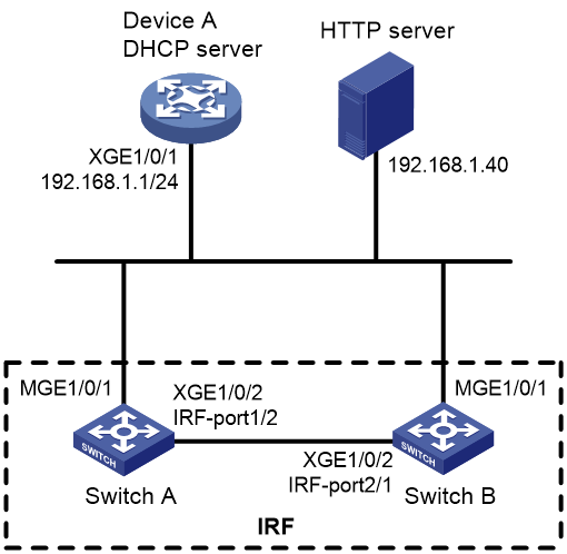
Network requirements
As shown in Figure 5, Switch A and Switch B do not have a configuration file.
Configure the servers so the switches can obtain a Python script to complete their respective configurations and form an IRF fabric.
Configuration procedure
1. Assign IP addresses to the interfaces. Make sure the devices can reach each other. (Details not shown.)
2. Configure the following files on the HTTP server:
|
File |
Content |
Remarks |
|
.cfg configuration file |
Commands required for IRF setup. |
You can create a configuration file by copying and modifying the configuration file of an existing IRF fabric. |
|
sn.txt |
Serial numbers of the member switches. |
Each SN uniquely identifies a switch. These SNs will be used for assigning a unique IRF member ID to each member switch. |
|
(Optional.) .ipe or .bin software image file |
Software images. |
If the member switches are running different software versions, you must prepare the software image file used for software upgrade. |
|
.py Python script file |
Python commands that complete the following tasks: a (Optional.) Verify that the flash memory has sufficient space for the files to be downloaded. b Download the configuration file and sn.txt. c (Optional.) Download the software image file and specify it as the main startup image file. d Resolve sn.txt and assign a unique IRF member ID to each SN. e Specify the configuration file as the main next-startup configuration file. f Reboot the member switches. |
For more information about Python script configuration, see "Using Python." |
3. Configure Device A as the DHCP server:
# Enable DHCP.
<DeviceA> system-view
[DeviceA] dhcp enable
# Configure address pool 1 to assign IP addresses on the 192.168.1.0/24 subnet to clients.
[DeviceA] dhcp server ip-pool 1
[DeviceA-dhcp-pool-1] network 192.168.1.0 24
# Specify the URL of the script file for the clients.
[DeviceA-dhcp-pool-1] bootfile-name http://192.168.1.40/device.py
[DeviceA-dhcp-pool-1] quit
# Enable the DHCP server on Ten-GigabitEthernet 1/0/1.
[DeviceA] interface ten-gigabitethernet 1/0/1
[DeviceA-Ten-GigabitEthernet1/0/1] dhcp select server
[DeviceA-Ten-GigabitEthernet1/0/1] quit
4. Power on Switch A and Switch B.
Switch A and Switch B will obtain the Python script file from the DHCP server and execute the script. After completing the IRF configuration, Switch A and Switch B reboot.
5. After Switch A and Switch B start up again, use a cable to connect Switch A and Switch B through their IRF physical ports.
Switch A and Switch B will elect a master member. The subordinate member will reboot to join the IRF fabric.
Verifying the configuration
# On Switch A, display IRF member devices. You can also use the display irf command on Switch B to display IRF member devices.
<Switch A> display irf
MemberID Slot Role Priority CPU-Mac Description
1 1 Standby 1 00e0-fc0f-8c02 ---
*+2 1 Master 30 00e0-fc0f-8c14 ---
--------------------------------------------------
* indicates the device is the master.
+ indicates the device through which the user logs in.
The Bridge MAC of the IRF is: 000c-1000-1111
Auto upgrade : yes
Mac persistent : always
Domain ID : 0
Auto merge : yes
The output shows that the switches have formed an IRF fabric.