- Table of Contents
- Related Documents
-
| Title | Size | Download |
|---|---|---|
| 02-WLAN roaming center configuration | 254.83 KB |
Contents
Configuring the WLAN roaming center
Restrictions: Hardware compatibility with WLAN roaming center
WLAN roaming center tasks at a glance
Enabling the WLAN roaming center
Specifying a port number for the WLAN roaming center
Setting the wait timer for user offline notification responses
Setting the maximum transmission attempts for user offline notification requests
Specifying portal roaming centers permitted by the WLAN roaming center
Display and maintenance commands for WLAN roaming center
WLAN roaming center configuration examples
Example: Configuring the WLAN roaming center
Configuring the WLAN roaming center
About the WLAN roaming center
A WLAN roaming center is an AC that manages information about wireless client authentication, authorization, and roaming to enable seamless inter-AC roaming. With the roaming center feature configured, clients can roam to another AC without being reauthenticated.
WLAN roaming center supports only portal authentication. For more information about inter-AC roaming for portal users, see portal in User Access and Authentication Configuration Guide.
Operating mechanism
As shown in Figure 1, a roaming center network must contain the following components:
· WLAN roaming center—An AC enabled with the WLAN roaming center feature. It manages client roaming and can also act as a portal roaming center to provide wireless services. Each network can have only one WLAN roaming center.
· Portal roaming centers—ACs enabled with the portal roaming center feature to provide access and roaming services to clients, AC 1 and AC 2 for example.

In a roaming center network, the WLAN roaming center feature operates as follows:
1. The AC with which a client attempts to associate sends a user query request to the WLAN roaming center. Upon receiving the request, the WLAN roaming center replies with a user query response.
2. When the client comes online, the AC sends a user online request to the WLAN roaming center.
¡ If it is the first time the client comes online, the WLAN roaming center creates a client entry and replies with a user online response.
¡ If the client has come online from another AC and roams to the AC, the WLAN roaming center updates the client entry and then replies with a user online response.
3. When the client goes offline, the AC sends a user offline request to the WLAN roaming center. Upon receiving the packet, the WLAN roaming center removes the AC from the access device list and replies with a user offline response. Then, the WLAN roaming center sends user offline notification requests to the other ACs in the access device list and removes the client entry after receiving responses from the ACs.
Restrictions: Hardware compatibility with WLAN roaming center
|
Hardware series |
Model |
Product code |
WLAN roaming center compatibility |
|
WX1800H series |
WX1804H |
EWP-WX1804H-PWR-CN |
No |
|
WX2500H series |
WX2508H-PWR-LTE WX2510H WX2510H-F WX2540H WX2540H-F WX2560H |
EWP-WX2508H-PWR-LTE EWP-WX2510H-PWR EWP-WX2510H-F-PWR EWP-WX2540H EWP-WX2540H-F EWP-WX2560H |
No |
|
WX3000H series |
WX3010H WX3010H-X WX3010H-L WX3024H WX3024H-L WX3024H-F |
EWP-WX3010H EWP-WX3010H-X-PWR EWP-WX3010H-L-PWR EWP-WX3024H EWP-WX3024H-L-PWR EWP-WX3024H-F |
No |
|
WX3500H series |
WX3508H WX3510H WX3520H WX3520H-F WX3540H |
EWP-WX3508H EWP-WX3510H EWP-WX3520H EWP-WX3520H-F EWP-WX3540H |
Yes: · WX3510H · WX3520H · WX3540H · WX3520H-F No: WX3508H |
|
WX5500E series |
WX5510E WX5540E |
EWP-WX5510E EWP-WX5540E |
Yes |
|
WX5500H series |
WX5540H WX5560H WX5580H |
EWP-WX5540H EWP-WX5560H EWP-WX5580H |
Yes |
|
Access controller modules |
LSUM1WCME0 EWPXM1WCME0 LSQM1WCMX20 LSUM1WCMX20RT LSQM1WCMX40 LSUM1WCMX40RT EWPXM2WCMD0F EWPXM1MAC0F |
LSUM1WCME0 EWPXM1WCME0 LSQM1WCMX20 LSUM1WCMX20RT LSQM1WCMX40 LSUM1WCMX40RT EWPXM2WCMD0F EWPXM1MAC0F |
Yes: · LSUM1WCME0 · EWPXM1WCME0 · LSQM1WCMX40 · LSUM1WCMX40RT · EWPXM1MAC0F No: · LSQM1WCMX20 · LSUM1WCMX20RT · EWPXM2WCMD0F |
|
Hardware series |
Model |
Product code |
WLAN roaming center compatibility |
|
WX1800H series |
WX1804H WX1810H WX1820H WX1840H |
EWP-WX1804H-PWR EWP-WX1810H-PWR EWP-WX1820H EWP-WX1840H-GL |
No |
|
WX3800H series |
WX3820H WX3840H |
EWP-WX3820H-GL EWP-WX3840H-GL |
Yes |
|
WX5800H series |
WX5860H |
EWP-WX5860H-GL |
Yes |
WLAN roaming center tasks at a glance
To configure the WLAN roaming center, perform the following tasks:
1. Enabling the WLAN roaming center
2. (Optional.) Specifying a port number for the WLAN roaming center
3. (Optional.) Setting the wait timer for user offline notification responses
4. (Optional.) Setting the maximum transmission attempts for user offline notification requests
5. (Optional.) Specifying portal roaming centers permitted by the WLAN roaming center
Enabling the WLAN roaming center
Restrictions and guidelines
You can enable the WLAN roaming center on only one AC in a network.
Disabling the WLAN roaming center feature deletes all portal client information.
Procedure
1. Enter system view.
system-view
2. Create a WLAN roaming center and enter its view.
wlan roaming-center
3. Enable the WLAN roaming center.
roaming-center enable
By default, the WLAN roaming center is disabled.
Specifying a port number for the WLAN roaming center
About this task
The WLAN roaming center uses the specified port number to communicate with portal roaming centers.
Restrictions and guidelines
Make sure the port specified for the WLAN roaming center is the same as the port specified for portal roaming centers.
Changing the port number when portal clients are online might cause information synchronization failure between the WLAN roaming center and portal roaming centers. Portal clients might fail to roam and must be reauthenticated.
As a best practice to avoid data residual, disable the WLAN roaming center before you change the port number.
Procedure
1. Enter system view.
system-view
2. Create a WLAN roaming center and enter its view.
wlan roaming-center
3. Specify a port number for the WLAN roaming center.
port port-number
By default, the WLAN roaming center uses port 1088.
Setting the wait timer for user offline notification responses
About this task
After sending a user offline notification request to an AC, the WLAN roaming center resends the request if it fails to receive a response before the wait timer expires. If it fails to receive any response after the maximum transmission attempt limit is reached, the WLAN roaming center deletes the timeout timer and removes the AC from the access device list of the client.
Procedure
1. Enter system view.
system-view
2. Create a WLAN roaming center and enter its view.
wlan roaming-center
3. Set the wait timer for user offline notification responses.
response-timeout timeout
By default, the wait timer for user offline notification responses is 3 seconds.
Setting the maximum transmission attempts for user offline notification requests
About this task
After sending a user offline notification request to an AC, the WLAN roaming center resends the request if it fails to receive a response before the wait timer expires. If it fails to receive any response after the maximum transmission attempt limit is reached, the WLAN roaming center deletes the timeout timer and removes the AC from the access device list of the client.
Procedure
1. Enter system view.
system-view
2. Create a WLAN roaming center and enter its view.
wlan roaming-center
3. Set the maximum transmission attempts for user offline notification requests.
retry retries
By default, the maximum number of transmission attempts for user offline notification requests is 5.
Specifying portal roaming centers permitted by the WLAN roaming center
About this task
This feature enables the WLAN roaming center to process packets only from the permitted portal roaming centers, enhancing network security. If no permitted portal roaming centers are specified, the WLAN roaming center processes packets from all portal roaming centers.
Procedure
1. Enter system view.
system-view
2. Create a WLAN roaming center and enter its view.
wlan roaming-center
3. Specify the IP address of a portal roaming center permitted by the WLAN roaming center.
control-access { bas-ip ipv4-address | bas-ipv6 ipv6-address }
By default, no permitted portal roaming center is specified.
Display and maintenance commands for WLAN roaming center
Execute display commands in any view and reset commands in user view.
|
Task |
Command |
|
Display offline client history on the WLAN roaming center. |
display wlan roaming-center history user { all | ip ipv4-address | ipv6 ipv6-address | mac mac-address } |
|
Display packet statistics on the WLAN roaming center. |
display wlan roaming-center statistics packet [ bas-ip ipv4-address | bas-ipv6 ipv6-address ] |
|
Display client information on the WLAN roaming center. |
display wlan roaming-center user { all | bas-ip ipv4-address | bas-ipv6 ipv6-address | ip ipv4-address | ipv6 ipv6-address | mac mac-address } [ verbose ] |
|
Clear client history information on the WLAN roaming center. |
reset wlan roaming-center history user { all | ip ipv4-address | ipv6 ipv6-address | mac mac-address } |
|
Clear packet statistics on the WLAN roaming center. |
reset wlan roaming-center statistics packet [ bas-ip ipv4-address | bas-ipv6 ipv6-address ] |
|
Clear client information on the WLAN roaming center. |
reset wlan roaming-center user { all | bas-ip ipv4-address | bas-ipv6 ipv6-address | ip ipv4-address | ipv6 ipv6-address | mac mac-address } |
WLAN roaming center configuration examples
Example: Configuring the WLAN roaming center
Network configuration
As shown in Figure 2, configure AC 1 as the WLAN roaming center and AC 2 and AC 3 as portal roaming centers to enable the client to roam from AC 2 to AC 3 without being authenticated.

Configuring AC 1
# Create a WLAN roaming center and enter its view.
<AC1> system-view
[AC1] wlan roaming-center
# Specify the port used by the WLAN roaming center as port 40000.
[AC1-wlan-roaming-center] port 40000
# Enable the WLAN roaming center.
[AC1-wlan-roaming-center] roaming-center enable
[AC1-wlan-roaming-center] quit
Configuring AC 2
1. Assign IP addresses to interfaces and make sure the client, server, and AC can reach each other. (Details not shown.)
2. Configure a RADIUS scheme:
# Create RADIUS scheme rs1 and enter its view.
<AC2> system-view
[AC2] radius scheme rs1
# Specify the primary authentication server and primary accounting server, and configure the keys for communication with the servers.
[AC2-radius-rs1] primary authentication 192.168.0.112
[AC2-radius-rs1] primary accounting 192.168.0.112
[AC2-radius-rs1] key authentication simple radius
[AC2-radius-rs1] key accounting simple radius
# Exclude the ISP domain name from the username sent to the RADIUS server.
[AC2-radius-rs1] user-name-format without-domain
[AC2-radius-rs1] quit
# Enable RADIUS session control.
[AC2] radius session-control enable
3. Configure an authentication domain:
# Create an ISP domain named dm1 and enter its view.
[AC2] domain dm1
# Configure AAA methods for the ISP domain.
[AC2-isp-dm1] authentication portal radius-scheme rs1
[AC2-isp-dm1] authorization portal radius-scheme rs1
[AC2-isp-dm1] accounting portal radius-scheme rs1
[AC2-isp-dm1] quit
# Configure domain dm1 as the default ISP domain. If a user uses a username without the ISP domain name at login, the authentication and accounting methods of the default domain are used for the user.
[AC2] domain default enable dm1
4. Configure portal authentication:
# Configure a portal authentication server.
[AC2] portal server newpt
[AC2-portal-server-newpt] ip 192.168.0.111 key simple portal
[AC2-portal-server-newpt] port 50100
[AC2-portal-server-newpt] quit
# Configure a portal Web server.
[AC2] portal web-server newpt
[AC2-portal-websvr-newpt] url http://192.168.0.111:8080/portal
[AC2-portal-websvr-newpt] quit
# Create AP ap2 and specify the AP model and serial ID.
[AC2] wlan ap ap2 model WA4320i-ACN
[AC2-wlan-ap-ap2] serial-id 210235A29G007C000020
[AC2-wlan-ap-ap2] quit
# Create service template newst and set the SSID to portal_1.
[AC2] wlan service-template newst
[AC2–wlan-st-newst] ssid portal_1
# Enable direct portal authentication.
[AC2–wlan-st-newst] portal enable method direct
# Apply portal Web server newpt.
[AC2–wlan-st-newst] portal apply web-server newpt
# Configure the BAS-IP as 192.168.0.110 for portal packets sent to the portal authentication server.
[AC2–wlan-st-newst] portal bas-ip 192.168.0.110
# Configure APs to forward client data traffic.
[AC2–wlan-st-newst] client forwarding-location ap
# Enable the service template.
[AC2–wlan-st-newst] service-template enable
[AC2–wlan-st-newst] quit
# Specify the working channel of radio 2 on AP ap2 as 11.
[AC2] wlan ap ap2
[AC2-wlan-ap-ap2] radio 2
[AC2-wlan-ap-ap2-radio-2] channel 11
# Enable radio 2. Apply service template newst and bind VLAN 2 to the radio.
[AC2-wlan-ap-ap2-radio-2] radio enable
[AC2-wlan-ap-ap2-radio-2] service-template newst vlan 2
[AC2-wlan-ap-ap2-radio-2] quit
[AC2-wlan-ap-ap2] quit
5. Configure the portal roaming center:
# Enter portal roaming center view.
[AC2] portal roaming-center
# Specify the IP address of the WLAN roaming center as 192.168.1.1.
[AC2-portal-roaming-center] ip 192.168.1.1
# Configure the portal roaming center to use port 4000 to communicate with the WLAN roaming center.
[AC2-portal-roaming-center] port 40000
# Set the wait timer for user offline notification responses to 5 seconds.
[AC2-portal-roaming-center] response-timeout 5
# Set the maximum transmission attempts for packets sent to the WLAN roaming center to 3.
[AC2-portal-roaming-center] retry 3
# Enable the portal roaming center.
[AC2-portal-roaming-center] roaming-center enable
[AC2-portal-roaming-center] quit
Configuring AC 3
# Configure AC 3 in the same way AC 2 is configured.
Configuring the AAA server
1. Configure the RADIUS server correctly for the server to provide authentication and accounting functions. (Details not shown.)
2. Configure the portal authentication server:
|
|
NOTE: In this example, the portal server runs on IMC PLAT 7.1(E0303) and IMC EIA 7.1(E0304). |
a. Log in to IMC and click the User tab.
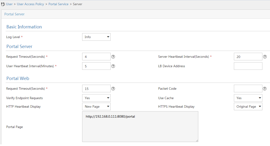
b. Select User Access Policy > Portal Service > Server from the navigation pane, as shown in Figure 3.
c. Configure the portal server parameters as needed.
This example uses the default settings.
d. Click OK.
Figure 3 Configuring the portal server
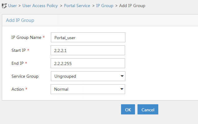
3. Configure the IP address group:
a. Select User Access Policy > Portal Service > IP Group from the navigation pane.
b. Click Add.
c. Enter the IP group name.
d. Enter the start IP address and end IP address of the IP group.
Make sure the host IP address is in the IP group.
e. Select a service group.
This example uses the default group Ungrouped.
f. Select Normal from the Action list.
g. Click OK.
Figure 4 Adding an IP address group
4. Add a portal device:
a. Select User Access Policy > Portal Service > Device from the navigation pane.
b. Click Add.
c. Enter the device name NAS.
d. Enter the IP address of the interface that connects the router to the host.
e. Set whether to support the portal server heartbeat and user heartbeat functions.
In this example, No is selected for both Support Server Heartbeat and Support User Heartbeat.
f. Enter the key, which must be the same as that configured on the router.
g. Select Directly Connected as the Access Method.
h. Click OK.
Figure 5 Adding a portal device

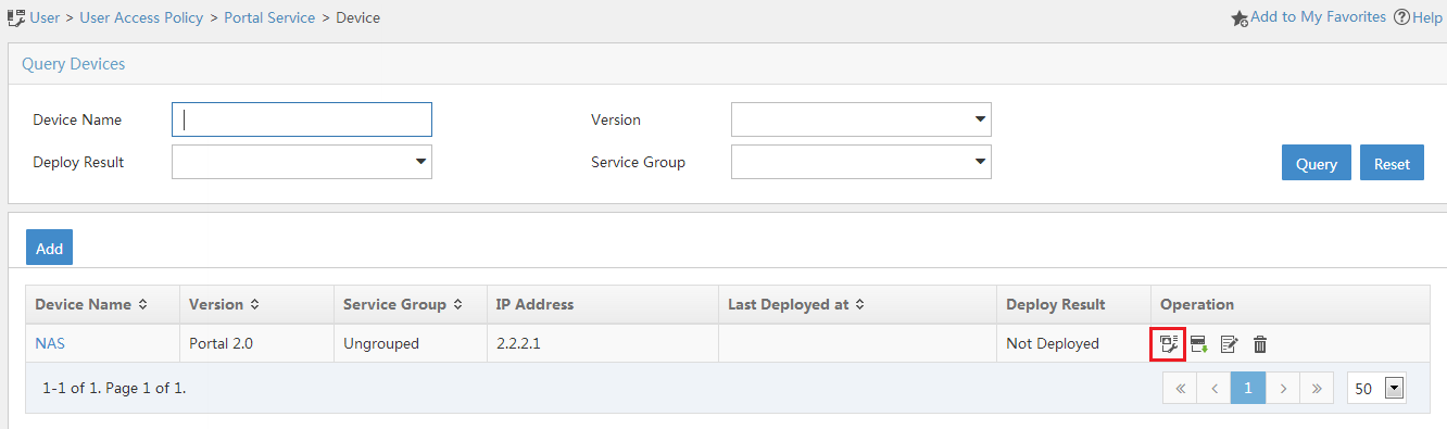
5. Associate the portal device with the IP address group:
a. As shown in Figure 6, click the Port Group Information Management icon for device NAS.
b. Click Add.
c. Enter the port group name.
d. Select the configured IP address group.
The IP address used by the user to access the network must be within this IP address group.
e. Use the default settings for other parameters.
f. Click OK.

6. Select User Access Policy > Service Parameters > Validate System Configuration from the navigation pane to validate the configurations.
Verifying the configuration
# Display client information on the WLAN roaming center.
[AC1] display wlan roaming-center user all
Total user: 1
MAC address IP address
000d-88f8-0eac 122.122.111.100
# Display detailed client roaming information on the WLAN roaming center.
[AC1] display wlan roaming-center user all verbose
MAC address: 000d-88f8-0eac
IP address: 122.122.111.100
Username: 1
Authorization information:
User profile: abc
ACL number/name: N/A
Inbound CAR: N/A
Outbound CAR: N/A
Session Timeout period: N/A
Idle cut: N/A
Roaming information:
Online BAS IP: 192.168.0.10
Online time: 12:01:12 01/02 2018 UTC
Roaming count: 3
BAS-IP Roam-in time
192.168.0.11 12:20:12 01/02 2018 UTC
192.168.0.10 12:18:12 01/02 2018 UTC