- Table of Contents
- Related Documents
-
| Title | Size | Download |
|---|---|---|
| 01-WLAN roaming configuration | 219.18 KB |
Contents
Restrictions and guidelines: WLAN roaming configuration
WLAN roaming tasks at a glance
Setting an authentication mode for IADTP control messages
Specifying an IP address type for IADTP tunnels
Specifying the source IP address for establishing IADTP tunnels
Setting the DSCP value for IADTP keepalive packets
Adding a mobility group member
Manually adding a mobility group member
Enabling automatic group member discovery
Specifying the mobility group member role of a device
Enabling tunnel isolation for mobility groups
Enabling SNMP notifications for WLAN roaming
Display and maintenance commands for WLAN roaming
WLAN roaming configuration examples
Example: Configuring intra-AC roaming
Example: Configuring inter-AC roaming
Configuring WLAN roaming
About WLAN roaming
WLAN roaming enables clients to seamlessly roam among APs in an ESS while retaining their IP address and authorization information during the roaming process.
Terminology
· Inter Access Device Tunneling Protocol—IADTP is an H3C-proprietary protocol that provides a generic packet encapsulation and transport mechanism for devices to securely communicate with each other. Devices that provide roaming services establish an IADTP tunnel with each other to exchange control messages and client information.
· Home AC—An HA is an AC that manages the AP with which a wireless client associates for the first time.
· Foreign AC—An FA is an AC with which a client associates after inter-AC roaming.
· Mobility group—A group that contains multiple member devices among which clients can roam.
IADTP tunnel establishment
A device in a mobility group can act as a client to initiate connection requests or act as a server to listen for and respond to the connection requests.
Figure 1 Establishing an IADTP tunnel
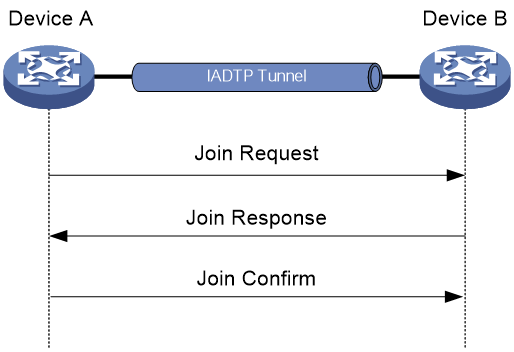
As shown in Figure 1, two devices establish an IADTP tunnel by using the following procedure:
1. Device A sends a join request to Device B.
2. Upon receiving the join request, Device B uses the local configuration and packet content to identify whether Device A is in the same mobility group.
¡ If they are in the same mobility group, Device B returns a join response with a result code representing success.
¡ If they are in different mobility groups, Device A returns a join response with a result code representing failure.
3. Upon receiving the join response, Device A examines the result code in the response.
¡ If the result code represents failure, Device A does not return any packets.
¡ If the result code represents success, Device A sends a join confirm to Device B.
4. Upon receiving the join confirm, Device B establishes an IADTP tunnel with Device A.
WLAN roaming mechanism
Clients can roam between devices in the same mobility group.
Intra-AC roaming
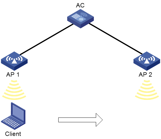
Intra-AC roaming enables clients to roam among APs that are managed by the same AC.

As shown in Figure 2, intra-AC roaming uses the following procedure:
1. The client comes online from AP 1, and the AC creates a roaming entry for the client.
2. The client roams to AP 2. The AC examines the roaming entry for the client and determines whether to perform fast roaming.
If the client uses RSN + 802.1X authentication and carries the same PMKID as the AC, fast roaming is used, and the client can associate with AP 2 without reauthentication. If it is not, the client must be reauthenticated before associating with AP 2.
Inter-AC roaming
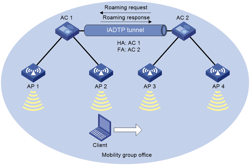
Inter-AC roaming enables clients to roam among APs that are managed by different ACs. These ACs must be in the same mobility group and have established an IADTP tunnel with each other.

As shown in Figure 3, inter-AC roaming uses the following procedure:
1. The client comes online from AP 2. AC 1 creates a roaming entry for the client and sends the information to AC 2 through the IADTP tunnel.
2. The client roams to AP 3. AC 2 examines the roaming entry for the client and determines whether to perform fast roaming.
If the client uses RSN + 802.1X authentication and carries the same PMKID as the AC, fast roaming is used, and the client can associate with AP 3 without reauthentication If it is not, the client must be reauthenticated before associating with AP 3.
3. The client associates with AP 3. AC 2 sends a roaming request to AC 1.
4. AC 1 verifies the roaming request and performs either of the following operations:
¡ Sends a roaming response that indicates roaming failure to AC 2 if the request is invalid. AC 2 logs off the client.
¡ Saves the roaming trace and roam-out information and sends a roaming response that indicates roaming success to AC 2 if the request is valid. AC 2 saves roaming-in information for the client.
Restrictions and guidelines: WLAN roaming configuration
For a service template where an AP is configured as the client authenticator, WLAN roaming is not supported. For more information about client authentication, see User Access and Authentication Configuration Guide.
For RSN + 802.1X clients from different VLANs to roam between devices within a mobility group, make sure uplink interfaces of the member devices permit all client VLANs.
WLAN roaming tasks at a glance
To configure WLAN roaming, perform the following tasks:
2. (Optional.) Setting an authentication mode for IADTP control messages
3. Specifying an IP address type for IADTP tunnels
4. Specifying the source IP address for establishing IADTP tunnels
5. (Optional.) Setting the DSCP value for IADTP keepalive packets
6. Adding a mobility group member
Perform one of the following tasks:
¡ Manually adding a mobility group member
¡ Enabling automatic group member discovery
7. (Optional.) Specifying the mobility group member role of a device
8. (Optional.) Disabling IADTP data tunnels
9. (Optional.) Enabling roaming relay
11. (Optional.) Enabling tunnel isolation for mobility groups
12. (Optional.) Enabling SNMP notifications for WLAN roaming
Creating a mobility group
Restrictions and guidelines
For inter-device roaming to operate correctly, create the same mobility group and add members to each device in the mobility group.
You can create only one mobility group on a device.
Procedure
1. Enter system view.
system-view
2. Create a mobility group and enter its view.
wlan mobility group group-name
Setting an authentication mode for IADTP control messages
About this task
This feature enables the device to verify the integrity of control messages transmitted over IADTP tunnels. WLAN roaming supports only the MD5 algorithm.
Procedure
1. Enter system view.
system-view
2. Enter mobility group view.
wlan mobility group group-name
3. Set an authentication mode for IADTP control messages.
authentication-mode authentication-mode { cipher | simple } string
By default, the device does not verify the integrity of IADTP control messages.
Specifying an IP address type for IADTP tunnels
About this task
You must specify an IP address type for IADTP tunnels after you create a mobility group.
Procedure
1. Enter system view.
system-view
2. Enter mobility group view.
wlan mobility group group-name
3. Specify an IP address type for IADTP tunnels.
tunnel-type { ipv4 | ipv6 }
By default, the IP address type for IADTP tunnels is IPv4.
Specifying the source IP address for establishing IADTP tunnels
About this task
A device uses the specified source IP address to establish IADTP tunnels with other member devices within the same mobility group.
Restrictions and guidelines
You can specify one IPv4 address, one IPv6 address, or both, but only the IP address type that is the same as the IP address type for IADTP tunnels takes effect.
Make sure the mobility group is disabled before you specify the source IP address for establishing IADTP tunnels.
Procedure
1. Enter system view.
system-view
2. Enter mobility group view.
wlan mobility group group-name
3. Specify the source IP address for establishing IADTP tunnels.
source { ip ipv4-address | ipv6 ipv6-address }
By default, no source IP address is specified for establishing IADTP tunnels.
Setting the DSCP value for IADTP keepalive packets
About this task
The DSCP value of an IP packet specifies the priority level of the packet and affects the transmission priority of the packet. A greater DSCP value means a higher packet priority.
In a scenario where a device establishes IADTP tunnels with other devices across NAT devices, two devices use IPsec for tunnel encryption and establishment. To prevent IADTP tunnel disconnection because the device cannot receive any IADTP keepalive packets from the peer when the IADTP tunnel is busy, set the DSCP value by using this feature.
Restrictions and guidelines
As a best practice, set the DSCP value to 63 for IADTP keepalive packets.
Procedure
1. Enter system view.
system-view
2. Enter mobility group view.
wlan mobility group group-name
3. Set the DSCP value for IADTP keepalive packets.
tunnel-dscp dscp-value
The default setting is 0.
Adding a mobility group member
Manually adding a mobility group member
About this task
Members in a mobility group are identified by their IP addresses used to establish IADTP tunnels.
You can add both IPv4 and IPv6 members to a mobility group. Only members whose IP address type is the same as the IP address type of IADTP tunnels take effect.
You can specify VLANs for a member, so that other members in the mobility group can directly forward client data of the member from the specified VLANs. If you do not specify VLANs for the member, its client data cannot be directly forwarded by another member in the mobility group unless the clients roam to that member.
Restrictions and guidelines
A device can belong to only one mobility group.
You can add a maximum of 31 IPv4 members and 31 IPv6 members to a mobility group.
When you specify VLANs for a mobility group member, follow these restrictions and guidelines:
· If a mobility group has multiple members, make sure no loops exist among IADTP tunnels between members within the mobility group.
· Make sure the VLANs have not been used by interfaces or services.
· Do not assign VLANs that have been specified for a member to interfaces or services.
Procedure
1. Enter system view.
system-view
2. Enter mobility group view.
wlan mobility group group-name
3. Add a mobility group member.
member { ip ipv4-address | ipv6 ipv6-address } [ vlan vlan-id-list ]
Enabling automatic group member discovery
About this task
Members in a mobility group are identified by their IP addresses used to establish IADTP tunnels. You can add both IPv4 and IPv6 members to a mobility group. Only members whose IP address type is the same as the IP address type of IADTP tunnels take effect.
This feature enables a device to automatically discover member devices in a mobility group by broadcasting its source IP address in the group. Member devices in the group that receive the IP address automatically establish IADTP tunnels with the device. The device joins the mobility group after it establishes IADTP tunnels with all the other members.
Restrictions and guidelines
A device can belong to only one mobility group.
You can add a maximum of 31 IPv4 members and 31 IPv6 members to a mobility group. When the maximum number is reached, the device stops establishing IADTP tunnels with newly discovered devices.
Prerequisites
Execute the source command to specify the source IP address used for establishing IADTP tunnels.
Procedure
1. Enter system view.
system-view
2. Enter mobility group view.
wlan mobility group group-name
3. Enable automatic group member discovery.
member auto-discovery [ interval interval ]
By default, automatic group member discovery is disabled.
Specifying the mobility group member role of a device
About this task
This feature applies to a scenario where a device establishes an IADTP tunnel with another device in the same mobility group across a NAT device. In this scenario, the device with a lower IP address acts as the client to initiate a connection request to the device with a higher IP address. If the device with a lower IP address resides in the public network, the IADTP tunnel cannot be established. To ensure successful establishment of the IADTP tunnel in this case, specify the device in the private network as the client to initiate the connection request.
Procedure
1. Enter system view.
system-view
2. Enter mobility group view.
wlan mobility group group-name
3. Specify the mobility group member role of the device.
role { client | server }
By default, a member device with a higher IP address acts as the server, and a member device with a lower IP address acts as the client.
Disabling IADTP data tunnels
About this task
|
|
CAUTION: To avoid data loss, do not disable IADTP data tunnels if no service ports are specified on the device for client VLANs. |
This feature enables a device to forward client traffic directly out of client VLANs' service ports, instead of through the IADTP data tunnel. This reduces the device's workload caused by processing broadcast packets received from IADTP data tunnels and saves resources for maintaining these tunnels.
Restrictions and guidelines
You must enable or disable IADTP tunnels on all devices in a mobility group.
You can configure this feature only when the mobility group is disabled.
Procedure
1. Enter system view.
system-view
2. Enter mobility group view.
wlan mobility group group-name
3. Disable IADTP data tunnels.
data-tunnel disable
By default, IADTP data tunnels are enabled.
Enabling roaming relay
About this task
In a WLAN, client roaming will gradually turn the WLAN into a fully meshed network because any two devices must establish a tunnel with each other for roaming entry exchanging. In a large network, establishing and maintaining such tunnels can consume a lot of bandwidth resources, increasing network complexity and reducing availability. Roaming relay is introduced to resolve this issue.
With this feature configured, the device enabled with roaming relay acts as a relay device to establish an IADTP tunnel with each non-relay device, forming a star topology. Non-relay devices do not need to establish tunnels with each other. These non-relay devices synchronize roaming entries to the relay device and, upon a client roaming, request the client entry from the relay device.
Restrictions and guidelines
Make sure the mobility group is disabled before you configure this feature.
To use roaming relay, you must enable roaming relay on a device and configure the device as the only mobility group member for the other devices in the same mobility group.
You can enable roaming relay on only one device in a mobility group.
If clients belong to different VLANs, make sure the tunnel interfaces on the relay device permit packets from all client VLANs.
Procedure
1. Enter system view.
system-view
2. Enter mobility group view.
wlan mobility group group-name
3. Enable roaming relay.
roam-relay enable
By default, roaming relay is disabled.
Enabling a mobility group
About this task
This feature enables the device to establish IADTP tunnels and synchronize roaming entries with member devices.
Procedure
1. Enter system view.
system-view
2. Enter mobility group view.
wlan mobility group group-name
3. Enable the mobility group.
group enable
By default, a mobility group is disabled.
Enabling tunnel isolation for mobility groups
About this task
Tunnel isolation prevents devices from forwarding packets between tunnels in a mobility group and avoids broadcast storm when loops exist among devices in the mobility group.
Procedure
1. Enter system view.
system-view
2. Enable tunnel isolation for mobility groups.
wlan mobility-group-isolation enable
By default, tunnel isolation is enabled for mobility groups.
Enabling SNMP notifications for WLAN roaming
About this task
To report critical WLAN roaming events to an NMS, enable SNMP notifications for WLAN roaming. For WLAN roaming event notifications to be sent correctly, you must also configure SNMP on the device. For more information about SNMP configuration, see Network Management and Monitoring Configuration Guide.
Procedure
1. Enter system view.
system-view
2. Enable SNMP notifications for WLAN roaming.
snmp-agent trap enable wlan mobility
By default, SNMP notifications for WLAN roaming are disabled.
Display and maintenance commands for WLAN roaming
Execute display commands in any view.
|
Task |
Command |
|
Display information about clients that have roamed to or from the device. |
display wlan mobility { roam-in | roam-out } [ member { ip ipv4-address | ipv6 ipv6-address }] |
|
Display mobility group information. |
|
|
Display roam-track information for a client on the HA. |
display wlan mobility roam-track mac-address mac-address |
WLAN roaming configuration examples
The AP models and serial numbers in this document are used only as examples. Support for AP models and serial numbers depends on the AC model.
Example: Configuring intra-AC roaming
Network configuration
As shown in Figure 4, configure intra-AC roaming to enable the client to roam from AP 1 to AP 2. The two APs are managed by the same AC.
Procedure
# Create a service template named service, set the SSID to 1, and enable the service template.
[AC] wlan service-template service
[AC-wlan-st-service] ssid 1
[AC-wlan-st-service] service-template enable
[AC-wlan-st-service] quit
# Create a manual AP named ap1, and specify the AP model and serial ID.
[AC] wlan ap ap1 model WA4320i-ACN
[AC-wlan-ap-ap1] serial-id 219801A0CNC13C004126
# Bind the service template to radio 1 of AP 1.
[AC-wlan-ap-ap1-radio-1] radio enable
[AC-wlan-ap-ap1-radio-1] service-template service
[AC-wlan-ap-ap1-radio-1] quit
[AC-wlan-ap-ap1] quit
# Create a manual AP named ap2, and specify the AP model and serial ID.
[AC] wlan ap ap2 model WA4320i-ACN
[AC-wlan-ap-ap2] serial-id 219801A0CNC125002216
# Bind the service template to radio 1 of AP 2.
[AC-wlan-ap-ap2-radio-1] radio enable
[AC-wlan-ap-ap2-radio-1] service-template service
[AC-wlan-ap-ap2-radio-1] quit
[AC-wlan-ap-ap2] quit
Verifying the configuration
# Enable the client to come online from AP 1. (Details not shown.)
# Verify that the client has associated with AP 1, and the roaming status is N/A, which indicates that the client has not performed any roaming.
[AC] display wlan client verbose
Total number of clients: 1
MAC address : 9cd3-6d9e-6778
IPv4 address : 10.1.1.114
IPv6 address : N/A
Username : N/A
AID : 1
AP ID : 1
AP name : ap1
Radio ID : 1
SSID : 1
BSSID : 000f-e200-4444
VLAN ID : 1
Sleep count : 242
Wireless mode : 802.11ac
Channel bandwidth : 80MHz
SM power save : Enabled
SM power save mode : Dynamic
Short GI for 20MHz : Supported
Short GI for 40MHz : Supported
Short GI for 80MHz : Supported
Short GI for 160/80+80MHz : Not supported
STBC RX capability : Not supported
STBC TX capability : Not supported
LDPC RX capability : Not supported
SU beamformee capability : Not supported
MU beamformee capability : Not supported
Beamformee STS capability : N/A
Block Ack : TID 0 In
Supported VHT-MCS set : NSS1 0, 1, 2, 3, 4, 5, 6, 7, 8
NSS2 0, 1, 2, 3, 4, 5, 6, 7, 8
Supported HT MCS set : 0, 1, 2, 3, 4, 5, 6, 7,
8, 9, 10, 11, 12, 13, 14,
15, 16, 17, 18, 19, 20,
21, 22, 23
Supported rates : 6, 9, 12, 18, 24, 36,
48, 54 Mbps
QoS mode : WMM
Listen interval : 10
RSSI : 62
Rx/Tx rate : 130/11
Authentication method : Open system
Security mode : PRE-RSNA
AKM mode : Not configured
Cipher suite : N/A
User authentication mode : Bypass
Authorization ACL ID : 3001(Not effective)
Authorization user profile : N/A
Roam status : N/A
Key derivation : SHA1
PMF status : Enabled
Forward policy name : Not configured
Online time : 0days 0hours 1minutes 13seconds
FT status : Inactive
# Verify that the AC has a roaming entry for the client.
[AC] display wlan mobility roam-track mac-address 9cd3-6d9e-6778
Total entries : 1
Current entries: 1
BSSID Created at Online time AC IP address RID AP name
000f-e200-4444 2016-06-14 11:12:28 00hr 01min 16sec 127.0.0.1 1 ap1
# Enable the client roam to AP 2. (Details not shown.)
# Verify that the client has associated with AP 2, and the roaming status is Intra-AC roam.
[AC] display wlan client verbose
Total number of clients: 1
MAC address : 9cd3-6d9e-6778
IPv4 address : 10.1.1.114
IPv6 address : N/A
Username : N/A
AID : 1
AP ID : 2
AP name : ap2
Radio ID : 1
SSID : 1
BSSID : 000f-e203-7777
VLAN ID : 1
Sleep count : 242
Wireless mode : 802.11ac
Channel bandwidth : 80MHz
SM power save : Enabled
SM power save mode : Dynamic
Short GI for 20MHz : Supported
Short GI for 40MHz : Supported
Short GI for 80MHz : Supported
Short GI for 160/80+80MHz : Not supported
STBC RX capability : Not supported
STBC TX capability : Not supported
LDPC RX capability : Not supported
SU beamformee capability : Not supported
MU beamformee capability : Not supported
Beamformee STS capability : N/A
Block Ack : TID 0 In
Supported VHT-MCS set : NSS1 0, 1, 2, 3, 4, 5, 6, 7, 8
NSS2 0, 1, 2, 3, 4, 5, 6, 7, 8
Supported HT MCS set : 0, 1, 2, 3, 4, 5, 6, 7,
8, 9, 10, 11, 12, 13, 14,
15, 16, 17, 18, 19, 20,
21, 22, 23
Supported rates : 6, 9, 12, 18, 24, 36,
48, 54 Mbps
QoS mode : WMM
Listen interval : 10
RSSI : 62
Rx/Tx rate : 130/11
Authentication method : Open system
Security mode : PRE-RSNA
AKM mode : Not configured
Cipher suite : N/A
User authentication mode : Bypass
Authorization ACL ID : 3001(Not effective)
Authorization user profile : N/A
Roam status : Intra-AC roam
Key derivation : SHA1
PMF status : Enabled
Forward policy name : Not configured
Online time : 0days 0hours 5minutes 13seconds
FT status : Inactive
# Verify that the AC has updated the roaming entry for the client.
[AC] display wlan mobility roam-track mac-address 9cd3-6d9e-6778
Total entries : 2
Current entries: 2
BSSID Created at Online time AC IP address RID AP name
000f-e203-7777 2016-06-14 11:12:28 00hr 01min 02sec 127.0.0.1 1 ap2
000f-e200-4444 2016-06-14 11:12:04 00hr 03min 51sec 127.0.0.1 1 ap1
Example: Configuring inter-AC roaming
Network configuration
As shown in Figure 5, configure inter-AC roaming to enable the client to roam from AP 2 to AP 3 that are managed by different ACs.
Procedure
1. Configure AC 1:
# Create a service template named service, set the SSID to office, and enable the service template.
[AC1] wlan service-template service
[AC1-wlan-st-test] ssid office
[AC1-wlan-st-test] service-template enable
[AC1-wlan-st-test] quit
# Create a manual AP named ap1, and specify the AP model and serial ID.
[AC1] wlan ap ap1 model WA4320i-ACN
[AC1-wlan-ap-ap1] serial-id 219801A0CNC138011454
# Bind the service template to radio 1 of AP 1.
[AC1-wlan-ap-ap1] radio 1
[AC1-wlan-ap-ap1-radio-1] radio enable
[AC1-wlan-ap-ap1-radio-1] service-template service
[AC1-wlan-ap-ap1-radio-1] quit
[AC1-wlan-ap-ap1] quit
# Create a manual AP named ap2, and specify the AP model and serial ID.
[AC1] wlan ap ap2 model WA4320i-ACN
[AC1-wlan-ap-ap2] serial-id 219801A0CNC138011445
# Bind the service template to radio 1 of AP 2.
[AC1-wlan-ap-ap2-radio-1] radio enable
[AC1-wlan-ap-ap2-radio-1] service-template service
[AC1-wlan-ap-ap2-radio-1] quit
[AC1-wlan-ap-ap2] quit
# Create a mobility group named office.
[AC1] wlan mobility group office
# Specify the IP address type for IADTP tunnels as IPv4.
[AC1-wlan-mg-office] tunnel-type ipv4
# Specify the source IP address for establishing IADTP tunnels as 10.1.4.22.
[AC1-wlan-mg-office] source ip 10.1.4.22
# Add AC 2 to the mobility group.
[AC1-wlan-mg-office] member ip 10.1.4.23
# Enable the mobility group.
[AC1-wlan-mg-office] group enable
[AC1-wlan-mg-office] quit
2. Configure AC 2:
# Create a service template named service, specify the SSID as office, and enable the service template.
[AC2] wlan service-template service
[AC2-wlan-st-service] ssid office
[AC2-wlan-st-service] service-template enable
[AC2-wlan-st-service] quit
# Create a manual AP named ap3, and specify the AP model and serial ID.
[AC2] wlan ap ap3 model WA4320i-ACN
[AC2-wlan-ap-ap3] serial-id 219801A0CNC138011439
# Bind the service template to radio 1 of AP 3.
[AC2-wlan-ap-ap3-radio-1] radio enable
[AC2-wlan-ap-ap3-radio-1] service-template service
[AC2-wlan-ap-ap3-radio-1] quit
[AC2-wlan-ap-ap3] quit
# Create a manual AP named ap4, and specify the AP model and serial ID.
[AC2] wlan ap ap4 model WA4320i-ACN
[AC2-wlan-ap-ap4] serial-id 219801A0CNC138011448
# Bind the service template to radio 1 of AP 4.
[AC2-wlan-ap-ap4] radio 1
[AC2-wlan-ap-ap4-radio-1] radio enable
[AC2-wlan-ap-ap4-radio-1] service-template service
[AC2-wlan-ap-ap4-radio-1] quit
[AC2-wlan-ap-ap4] quit
# Create a mobility group named office.
[AC2] wlan mobility group office
# Specify the IP address type for IADTP tunnels as IPv4.
[AC2-wlan-mg-office] tunnel-type ipv4
# Specify the source IP address for establishing IADTP tunnels as 10.1.4.23.
[AC2-wlan-mg-office] source ip 10.1.4.23
# Add AC 2 to the mobility group.
[AC2-wlan-mg-office] member ip 10.1.4.22
# Enable the mobility group.
[AC2-wlan-mg-office] group enable
[AC2-wlan-mg-office] quit
Verifying the configuration
# Verify that a mobility group has been created on AC 1.
[AC1] display wlan mobility group
Mobility group name: office
Tunnel type: IPv4
Source IPv4: 10.1.4.22
Source IPv6: Not configured
Authentication method: Not configured
Mobility group status: Enabled
Member entries: 1
IP address State Online time
10.1.4.23 Up 00hr 00min 12sec
# Verify that a mobility group has been created on AC 2.
[AC2] display wlan mobility group
Mobility group name: office
Tunnel type: IPv4
Source IPv4: 10.1.4.23
Source IPv6: Not configured
Authentication method: Not configured
Mobility group status: Enabled
Member entries: 1
IP address State Online time
10.1.4.22 Up 00hr 00min 05sec
# Get the client online on AP 2 and then make the client roam to AP 3. (Details not shown.)
# Display client roaming information on AC 1 to verify that the client has come online from AP 2 and roamed to AP 3.
[AC1] display wlan mobility roam-track mac-address 9cd3-6d9e-6778
Total entries : 2
Current entries: 2
BSSID Created at Online time AC IP address RID AP name
000f-e203-8889 2016-06-14 11:12:28 00hr 06min 56sec 10.1.4.23 1 ap3
000f-e203-7777 2016-06-14 11:11:28 00hr 03min 30sec 127.0.0.1 1 ap2
# On AC 1, verify that the client has roamed to AC 2.
<AC1> display wlan mobility roam-out
Total entries: 1
MAC address BSSID VLAN ID Online time FA IP address
9cd3-6d9e-6778 000f-e203-8889 1 00hr 01min 59sec 10.1.4.23
# On AC 2, verify that the client has associated with AP 3, and the roaming status is Inter-AC roam.
<AC2> display wlan client verbose
Total number of clients: 1
MAC address : 9cd3-6d9e-6778
IPv4 address : 10.1.1.114
IPv6 address : N/A
Username : N/A
AID : 1
AP ID : 3
AP name : ap3
Radio ID : 1
SSID : 1
BSSID : 000f-e203-8889
VLAN ID : 1
Sleep count : 242
Wireless mode : 802.11ac
Channel bandwidth : 80MHz
SM power save : Enabled
SM power save mode : Dynamic
Short GI for 20MHz : Supported
Short GI for 40MHz : Supported
Short GI for 80MHz : Supported
Short GI for 160/80+80MHz : Not supported
STBC RX capability : Not supported
STBC TX capability : Not supported
LDPC RX capability : Not supported
SU beamformee capability : Not supported
MU beamformee capability : Not supported
Beamformee STS capability : N/A
Block Ack : TID 0 In
Supported VHT-MCS set : NSS1 0, 1, 2, 3, 4, 5, 6, 7, 8
NSS2 0, 1, 2, 3, 4, 5, 6, 7, 8
Supported HT MCS set : 0, 1, 2, 3, 4, 5, 6, 7,
8, 9, 10, 11, 12, 13, 14,
15, 16, 17, 18, 19, 20,
21, 22, 23
Supported rates : 6, 9, 12, 18, 24, 36,
48, 54 Mbps
QoS mode : WMM
Listen interval : 10
RSSI : 62
Rx/Tx rate : 130/11
Authentication method : Open system
Security mode : PRE-RSNA
AKM mode : Not configured
Cipher suite : N/A
User authentication mode : Bypass
Authorization ACL ID : 3001(Not effective)
Authorization user profile : N/A
Roam status : Inter-AC roam
Key derivation : SHA1
PMF status : Enabled
Forward policy name : Not configured
Online time : 0days 0hours 5minutes 13seconds
FT status : Inactive
# Verify that the client has roamed from AC 1 to AC 2.
<AC2> display wlan mobility roam-in
Total entries: 1
MAC address BSSID VLAN ID HA IP address
9cd3-6d9e-6778 000f-e203-8889 1 10.1.4.22