- Table of Contents
- Related Documents
-
| Title | Size | Download |
|---|---|---|
| 01-Text | 10.05 MB |
Access and authentication methods
UAM and access device cooperation
UAM authentication architecture
UAM function in simple AAA authentication model
UAM authentication architecture description
Endpoint authentication schemes
UAM authentication configuration guide
802.1X authentication and UAM local authentication
Portal authentication and UAM local authentication
Transparent portal authentication
Account registering configuration
Transparent MAC authentication
VPN authentication and UAM local authentication
802.1X authentication and certificate authentication
Portal authentication and certificate authentication
UAM menus and common operations
Configuring service quick experience
Creating a service quick experience
Accessing service configuration wizard
Using the service fast deploy function
Configuring service fast deploy for guest MAC authentication
Configuring service fast deploy for employee MAC authentication
Configuring service fast deploy for employee 802.1X authentication
Configuring access period policies
Accessing the access period policy list page
Viewing access period policy details
Adding an access period policy
Modifying an access period policy
Deleting an access period policy
Configuring access location groups
Accessing the access location group list page
Querying access location groups
Viewing access location group details
Adding an access location group
Modifying an access location group
Deleting an access location group
Accessing the SSID group list page
Configuring endpoint IP groups
Accessing the endpoint IP group list page
Modifying an endpoint IP group
Configuring endpoint MAC groups
Viewing the endpoint MAC group list
Viewing endpoint MAC group details
Modifying an endpoint MAC group
Deleting an endpoint MAC group
Configuring endpoint vendor groups
Viewing the endpoint vendor group list
Querying endpoint vendor groups
Viewing endpoint vendor group details
Adding an endpoint vendor group
Modifying an endpoint vendor group
Deleting an endpoint vendor group
Configuring endpoint type groups
Accessing the endpoint type group list page
Viewing endpoint type group details
Modifying an endpoint type group
Deleting an endpoint type group
Configuring endpoint OS groups
Accessing the endpoint OS group list page
Viewing endpoint OS group details
Modifying an endpoint OS group
Accessing the AP group list page
Configuring user access policies
Accessing the access policy list page
Modifying the SSID access control type
Configuring hard disk serial numbers
Accessing the hard disk serial number list page
Modifying access rights for endpoints with hard disk serial numbers unobtained
Querying hard disk serial numbers
Adding a hard disk serial number
Importing hard disk serial numbers in batches
Modifying a hard disk serial number
Deleting hard disk serial numbers
Configuring access MAC addresses
Accessing the access MAC address list page
Importing access MAC addresses in batches
Modifying an access MAC address
Configuring motherboard serial numbers
Viewing the motherboard serial number list
Modifying access rights for endpoints with motherboard serial numbers unobtained
Querying endpoint motherboard serial numbers
Adding a motherboard serial number
Importing motherboard serial numbers in batches
Modifying a motherboard serial number
Deleting motherboard serial numbers
Accessing the access ACL list page
Viewing the access ACL details
Managing endpoint identification
Managing endpoint identification characters
Endpoint identification configuration example
Accessing the access service list page
Viewing access service details
Access users and platform users
Determining appropriate access user type
Determining authentication priorities
Managing ordinary access users
Accessing the access user list page
Querying ordinary access users
Viewing ordinary access user details
Adding an ordinary access user
Bulk importing ordinary access users
Bulk exporting ordinary access users
Modifying an ordinary access user
Bulk modifying ordinary access users
Temporarily canceling normal accounts
Restoring temporarily cancelled accounts to normal accounts
Deleting ordinary access users
Adding ordinary access users to the blacklist
Releasing ordinary access users from the blacklist
Applying for services for ordinary access users
Canceling a service for ordinary access users
Regrouping ordinary access users
Accessing the preregistered user list page
Viewing preregistered user details
Registering as an ordinary access user
Bulk registering as ordinary access users
Accessing the mute terminal user configuration profile list page
Viewing mute terminal user configuration profile details
Adding a mute terminal user configuration profile
Modifying a mute terminal user configuration profile
Activating mute terminal user configuration profiles
Deleting mute terminal user configuration profiles
Managing guest managers in UAM
Configuring guest services in UAM
Configuring guest service parameters
Customizing and printing guest information
Preregistering a guest on the self-service center login page (by a guest)
Managing preregistered guests in the self-service center (by a guest manager)
Managing registered guests in the self-service center (by a guest manager)
Preregistering a guest on the Guest Center login page
Managing preregistered guests in the Guest Center
Managing registered guests in the Guest Center
IMC administrator managing guests in UAM
Accessing the blacklisted user list page
Maintaining accounts in a file
Querying and maintaining accounts in batches
Exporting access details in batches
Batch canceling unbound platform users
Importing endpoint information
Modifying endpoint information
Configuring transparent authentication for endpoints
Associating users with an endpoint device
Clearing associated users for endpoint devices
Managing endpoint configurations
BYOD quick deployment process for iOS/OS X endpoints
BYOD quick deployment process for Android endpoints
BYOD quick deployment process for Windows PC endpoints
Configuring endpoint configuration templates
Configuring endpoint configuration distribution policies
Managing endpoint configuration tools
Managing the endpoint configuration history
Access device configuration tasks
Accessing the access device list page
Viewing the access device configuration
Setting whether to select devices from the IMC platform
Synchronizing port configurations on access devices
Deploying configurations to access devices
Configuring ARP spoofing attack protection
Configuring access device types
Accessing the Access Device Type List page
Viewing access device type details
Modifying an access device type
Deleting an access device type
Modifying the priority of an access device type
Configuring the Proprietary Attribute List
Configuring proprietary attribute assignment policies
Proprietary attribute assignment policy workflow
Accessing the Proprietary Attribute Assignment Policy List page
Viewing proprietary attribute assignment policy details
Adding a proprietary attribute assignment policy
Modifying a proprietary attribute assignment policy
Deleting a proprietary attribute assignment policy
Configuring portal authentication
Configuring UAM as the portal server
Accessing the IP Group List Page
Viewing IP address group details
Accessing the device list page
Accessing the port group list page
Deploying configurations to a portal device
Parameters for Comware V5 switches and routers
Parameters for Comware V3 switches and routers
Parameters for wireless devices
Viewing the configurations last deployed to a portal device
Configuring PDAs to support portal authentication
Configuring transparent portal authentication
Enabling transparent authentication for portal endpoints
Maintaining the transparent portal user list
Managing transparent authentication characters
Configuring MAC/BYOD authentication
Transparent MAC authentication
Configuring computer authentication
Configuring the iNode PC client
Using the built-in Windows 802.1X client
Configuring LDAP authentication
Accessing the LDAP server list page
Testing connectivity to an LDAP server
Modifying LDAP server settings
Batch-modifying LDAP server admin passwords
Managing LDAP synchronization policies
Accessing the LDAP synchronization policy list page
Querying LDAP synchronization policies
Viewing LDAP synchronization policy details
Adding an LDAP synchronization policy
Modifying an LDAP synchronization policy
Deleting an LDAP synchronization policy
Manually executing a synchronization policy
Managing users bound to an LDAP synchronization policy
Validating on-demand synchronization policies
Binding common users with LDAP synchronization policies
Unbinding LDAP users with an LDAP synchronization policy
Modifying LDAP user information
Adding an LDAP user to the blacklist
Releasing an LDAP user from the blacklist
Applying for services for LDAP users
Canceling services for LDAP users
Supplementary information for LDAP user passwords stored in UAM
Configuring certificate authentication
Implementing local certificate authentication for 802.1X or portal users
Managing root certificate, server certificate, and CRL in UAM
Importing root and server certificates to UAM
Verifying the imported certificates
Accessing the Certification Configuration List page
Deleting certificate configuration
Configuring a preferred EAP type in an access policy
Configuring RSA authentication
Configuring third-party RADIUS authentication
Configuring roaming authentication
Roaming authentication example
Roaming authentication prerequisites
Unavailable UAM functions in roaming authentication
Configuring the source UAM as an access device (on the destination UAM)
Configuring the roaming function (on the source UAM)
Accessing the roaming configuration list page
Modifying roaming configuration
Deleting roaming configuration
Configuring third-party authentication
Viewing third-party authentication configuration
Configuring the third-party database
Configuring the third-party Web service
Configuring the customized third-party plug-in
Configuring third-party RADIUS authentication
Viewing the third-party user list
Managing and applying portal page sets
Managing cell phone portal page sets
Applying portal page sets to users
Managing and applying preregistration page sets
Managing PC preregistration pages
Managing cell phone preregistration page sets
Applying preregistration page sets
Managing and applying BYOD page sets
Managing cell phone BYOD page sets
Customizing and applying self-service pages
Modifying the self-service login page for PCs
Modifying the self-service login page for mobile devices
Configuring PC menu customization policies
Modifying the Guest Center login page for PCs
Customizing the guest approval page for mobile devices
Configuring page push policies
Accessing the page push policy list page
Viewing page push policy details
Managing authentication failure logs
Managing access detail records
Managing roaming-access details records
Managing authentication violation logs
Managing device management user authentication logs
Managing endpoint conflict audit logs
Managing Internet access audit logs
Exporting LAN access detail records
Configuring messages delivered to the iNode client
Accessing the client message list page
Managing user SMS notifications
Accessing the SMS notification list page
Viewing SMS notification details
Adding a user SMS notification
Modifying a user SMS notification
Deleting a user SMS notification
Accessing the email message list page
Managing the access service topology function
Managing access service topology views
Accessing the access service topology view list page
Adding an access service topology view
Modifying an access service topology view
Deleting an access service topology view
Accessing an access service topology view
Adding a non-access device to an access service topology
Adding an access device to an access service topology
Deleting devices from an access service topology
Managing devices on an access service topology
Unmanaging devices on an access service topology
Synchronizing a device on an access service topology
Accessing an access service topology
Pinging a device on an access service topology
Telnetting to a device on an access service topology
Managing access service topologies
Accessing an access service topology
Configuring a device as an access device
Viewing access device information
Configuring an access device as a non-access device
Adding an online user to the blacklist
Authentication failure category statistics report
Endpoint device statistics report
Number of users per day report
Number of users per month report
Number of users per year report
Online User Count Monthly report
Test mode authentication failure log report
Authentication failure category statistics report
Top 5 access devices by online count
Configuring device management users
Configuring device user groups in UAM
Accessing the device user group list page
Configuring device management users in UAM
Accessing the device management user list page
Querying device management users
Viewing device management user details
Adding a device management user
Importing device management users in batches
Modifying device management users
Binding device management users with an LDAP synchronization policy
Deleting device management users
Configuring access devices in UAM
Configuring AAA authentication on devices
Viewing authentication logs of device management users in UAM
Accessing the trouble report question list page
Viewing trouble report question details
Adding a trouble report question
Modifying a trouble report question
Adjusting the priority of a trouble report question
Deleting a trouble report question
Managing trouble tickets in the Self-Service Center
Managing trouble tickets in UAM
Using FAQs in the Self-Service Center
Managing FAQs in the Guest Center
Managing user groups and service groups
Accessing the User Group List page
Viewing users in a user group or subgroup
Querying users in a user group or subgroup
Moving users between user groups
Limiting the maximum number of users in a group
Accessing the service group list page
Configuring global system settings
Configuring policy server parameters
Configuring user endpoint settings
Configuring endpoint aging policy parameters
Accessing the endpoint aging policy list page
Modifying the endpoint aging policy type
Adding an endpoint aging policy
Modifying an endpoint aging policy
Deleting an endpoint aging policy
Configuring UAM system operation log parameters
Configuring the password strategy
Managing auto-cancel accounts tasks
Accessing the auto-cancel accounts task list page
Adding an auto-cancel accounts task
Modifying an auto-cancel accounts task
Deleting an auto-cancel accounts task
Configuring wireless positioning parameters
Configuring user notification parameters
Accessing the user notification list page
Viewing the iNode management center list
Adding an iNode management center
Modifying the iNode management center description
Deleting the iNode management center
Configuring proxy server detection settings
Configuring the third-party authentication system
Configuring the cell phone number ranges
Viewing the Cell Phone Number Range List
Adding the cell phone number range
Importing cell phone number ranges in batches
Modifying the description of the cell phone number range
Deleting the cell phone number range
Configuring user binding information
Viewing user binding information
Setting the auto-learned number of binding parameters
Configuring alias authentication
Configuration restrictions and guides
Accessing the alias authentication configuration list page
Adding an alias authentication configuration entry
Modifying an alias authentication configuration entry
Deleting an alias authentication configuration entry
Modifying the daily validation time
Configuring client upgrade in UAM
Managing iNode PC client upgrade tasks
Managing iNode MC upgrade tasks
Configuring smart device client upgrade
Configuring unified authentication
Configuring Web Application System > Portal
Configuring Web Application System > Self-Service
Configuring Portal > Web Application System
Configuring iNode client shortcuts
Validating system settings manually
Using the PC version of the Self-Service Center
Maintaining accounts by access users
Maintaining user information by device management users
Using the touch version of the Self-Service Center
Logging in to the Self-Service Center
Maintaining personal information
Exiting the Self-Service Center
Using the PC version of the Guest Center
Using the touch version of the Guest Center
Accessing the guest management page
Registering a guest by mobile number
UAM overview
UAM in the EAD solution
UAM is a part of the EAD solution. It is a multi-service, secure access management solution that integrates authentication, monitoring, auditing, and service management.
In the EAD solution, IMC cooperates with various access devices (such as switches, routers, VPN gateways, and firewalls) to meet the requirements of identity authentication, user privilege control, access admission, and desktop management in different network scenarios.
The EAD solution has the following features:
· Reliable user identity authentication
· Simple and practical user management
· BYOD/endpoint identification
· Strict user privilege control
· All-around endpoint security protection
· Powerful desktop management function
· High-performance, expansible deployment solutions
The EAD solution uses a client/server model: UAM and EAD Security Policy as the servers, and the iNode client software as the client.
· The UAM component provides reliable user identity authentication, simple and practical user management, and strict user privilege control for the EAD solution.
· The EAD Security Policy component provides strict endpoint security defense and powerful desktop management for the EAD solution.
· The iNode client cooperates with the UAM and EAD Security Policy to implement these endpoint control functions.
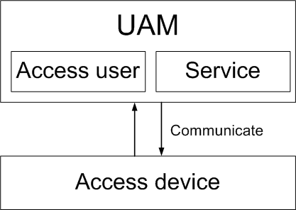
UAM functional structure
As shown in Figure 1, UAM functions are based on the access user and service structure.
· An access user is the information an endpoint user employs to access the network, including access account and password.
· A service is a set of access control policies.
To access the network, an endpoint user creates an access user and applies for at least one service in UAM. When accessing the network, the user is restricted by the policies defined in each service that the user employs.
Figure 1 UAM functional structure
UAM user types
To satisfy access requirements in different scenarios, UAM contains the following user types:
· Normal access users—Uses an account name-password or certificate to pass identity authentication. UAM saves and maintains user access information.
· Mute terminal users—Refers to a network terminal without an authentication operating interface, such as an IP phone and a printer. A mute terminal uses its MAC address for identity authentication.
· LDAP users—UAM users who are bound with an LDAP server. When UAM receives an authentication request from such a user, it delivers the user name and password to the LDAP server for identity authentication. LDAP user information is saved in both the LDAP server and the UAM server. The LDAP server maintains user information. UAM periodically synchronizes user information with the LDAP server.
If network users are managed by an LDAP server, use the LDAP user management function after you deploy the UAM system to the network.
· Guests—Refers to a user who needs to access the network. In UAM, you can specify a normal user as a guest administrator, who can add guest users and process the preregistration requests for guest users.
· Device management users—Manages network devices. When a device management user logs in to a network device through Telnet or SSH, UAM authenticates the user's account and password. UAM supports only RADIUS authentication for device management users. After a device management user passes authentication, UAM assigns corresponding management rights to the user, and then the user can manage and maintain the network device.
UAM access control settings
Access control policies are used in UAM services to control user access behaviors and avoid insecure user access. Access control policy categories include authorization, binding, and access area control.
Authorization
Authorization for users includes the following:
· Control user access time—UAM lets you define time ranges during which users can or cannot access the network. To implement time-range based network access, specify different access time ranges for different users.
· Control user uplink and downlink bandwidth and priorities—Access devices can limit the uplink and downlink speeds and priorities of access users according to rate and priority limit policies assigned by UAM. This function reduces network congestion by stopping users from occupying excessive network resources.
· Specify user access rights to resources—Access devices can dynamically grant users access to specific network resources, according to the user ACLs and user VLANs assigned by UAM. This function prevents illegal access to important network resources.
· Require the usage of an iNode client—Some UAM functions require the cooperation of an iNode client. UAM lets you specify that users must use an iNode client to ensure these functions.
· Prohibit users from using an IE proxy or proxy server software—If you enable this function in UAM, users who use an IE proxy or run proxy server software cannot pass authentication, and online users who configure an IE proxy or run a proxy server are logged off. This function requires the cooperation of the iNode client.
· Prohibit online users from changing IP addresses—If you enable this function in UAM, online users who change the IP address of the authentication network adapter are logged off. This function runs with the iNode client.
· Prohibit users from changing MAC addresses—If you enable this function in UAM, users who change the MAC address of the authentication network adapter cannot pass authentication. This function runs with the iNode client.
· Prohibit users from using multiple network adapters—If you enable this function in UAM, users who have multiple network adapters (including virtual network adapters) activated in their PCs cannot pass authentication. If it detects that an online user has multiple active network adapters, UAM logs off the user. This function runs with the iNode client.
· Prohibit users from using the iNode DC in Windows, Linux, or Mac OS—If you enable this function in UAM, users who use an iNode DC in the corresponding operating system cannot pass authentication.
· Access MAC address control—If you enable this function in UAM, users who use MAC addresses that are not allowed to access the network cannot pass authentication.
· Hard disk serial number control—If you enable this function in UAM, users can access the network only when at least one hard disk serial number of their terminals is allowed to access the network.
· SSID access control—If you enable this function in UAM, a wireless user must use a permitted SSID to access the network.
· Restrict external network access—If you enable this function in UAM, UAM uses client ACLs to restrict the network access rights of users who use an unauthenticated network adapter. This function runs with the iNode client.
· Restrict the method of getting a user IP—In UAM, you can specify the method of users getting IP addresses as DHCP, static configuration, or either DHCP or static. If a user obtains the IP address in a way different from that you specified, the user cannot pass authentication.
Binding
The following types of bindings can be used with one another unless otherwise specified:
· Access user and access device binding—Users can access the network only from the access device with a specific IP address. The IP address is specified in UAM.
· Access user and access port binding—Users can access the network only from a specific port on an access device. The port is specified in UAM.
· Access user and access device SN binding—Users can access the network only from an access device that uses the bound serial number.
· Access user and access VLAN binding—Users can access the network only from a specific VLAN on an access device. The VLAN is specified in UAM. You can use VLAN binding or QinQ VLAN binding but not both.
· Access user and QinQ VLAN binding—Users can access the network only when the user's inner and outer VLAN configuration matches the configuration specified in UAM. You can use VLAN binding or QinQ VLAN binding, but not both.
· Access user and PC's IPv6 address binding—Users can access the network only when the IPv6 address of the network adapter that the user uses for authentication matches the configuration specified in UAM.
· Access user and PC's MAC address binding—Users can access the network only when the MAC address of the network adapter that the user uses for authentication matches the configuration specified in UAM.
· Access user and SSID binding—Wireless users can access the network only when the user uses the SSID specified in UAM.
· Access user and PC name binding—Users can access the network only when the user's PC name matches the PC name specified in UAM.
· PC and domain binding—Users can access the network only when the user's PC is added to the domain specified in UAM.
· PC and login-domain binding—Users can access the network only if the user logs in to a domain when logging in to the PC operating system.
Access and authentication methods
A UAM authentication system contains UAM, access devices, and clients, as shown in Figure 2.
· An access method refers to the exchange between a client and its access device.
· An authentication method refers to the exchange between an access device and UAM.
An access method and an authentication method work together to implement user identity authentication.
Access methods
UAM supports 802.1X, portal, VPN, and MAC authentication.
Authentication methods
UAM supports UAM local authentication, LDAP authentication, RSA authentication, and roaming authentication.
802.1X access
Application scenarios
· New network construction, or large-scale rebuilding of an existing network.
· Strict access control at the network access layer.
Figure 2 Network diagram of 802.1X access
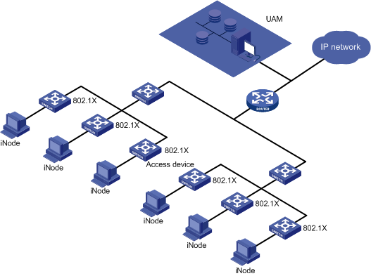
Features
802.1X access has the following features:
· UAM serves as the RADIUS server to authenticate user identities.
· Access layer switches determine whether endpoint users can access the network.
· Access layer switches grant user access rights to resources according to the access control policies assigned by UAM.
Password exchange methods
The 802.1X access process supports the following password exchange methods:
· CHAP
· EAP-MD5
· EAP-PEAP
· EAP-TLS
· EAP-TTLS
· PAP
Portal access
Web portal authentication does not support EAP-MD5, EAP-TLS, or EAP-PEAP.
Application scenarios
· Small-scale rebuilding of an existing network.
· User access control at the network distribution layer.
· Control access only to the external network. Users can access the internal network, but must pass authentication to access the external network.
Figure 3 Network diagram of portal access
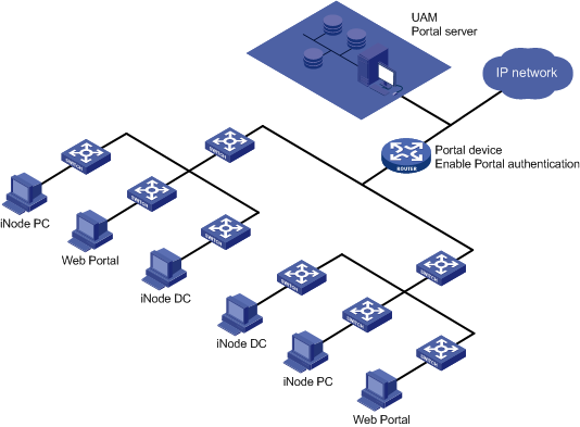
Features
Portal access has the following features:
· UAM serves as both the RADIUS server and the portal server.
· The network distribution layer, core layer (portal gateway attached), or egress device controls user access to the network.
Password exchange methods
The portal access process supports the following password exchange methods:
· CHAP
· EAP-MD5
· EAP-PEAP
· EAP-TLS
· EAP-TTLS
· PAP
VPN access
UAM supports these VPN access methods:
· L2TP
· IPsec + L2TP
Application scenarios
· Branches need to access the internal network of the headquarters.
· Mobile employees need to access the internal network of the headquarters.
· Partners need to access some internal network resources of the headquarters.
Figure 4 Network diagram of VPN access
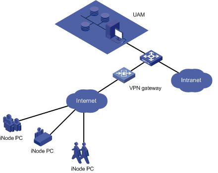
Features
VPN access has the following features:
· UAM serves as the RADIUS server to authenticate user identities.
· The L2TP VPN gateway controls user access to the Intranet.
· The L2TP VPN gateway grants user access rights to resources according to the access control policies assigned by UAM.
MAC authentication
Application scenarios
MAC authentication, shown in Figure 5, is typically used to authenticate mute terminals. A mute terminal refers to a network terminal without an authentication interface, such as an IP phone or a printer.
Figure 5 Network diagram of MAC authentication
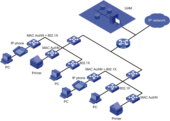
Features
MAC authentication has the following features:
· UAM serves as the RADIUS server to authenticate user identities.
· Access layer switches determine whether mute terminals can access the network.
· If a PC is attached to an IP phone, you must enable both MAC authentication and 802.1X authentication on the port of the access layer switch. MAC authentication applies to the IP phone, and 802.1X authentication applies to the PC user.
UAM local authentication
In UAM local authentication, user data is saved in UAM and UAM authenticates user identities.
If a user is valid, UAM informs the access device to permit network access, and assigns access control policies to the access device. The access device then controls user access to network according to the policies.
LDAP authentication
Application scenarios
LDAP authentication, shown in Figure 6, is used in a network that uses an LDAP server to manage users. You only need to periodically synchronize user information from the LDAP server to UAM.
Figure 6 Network diagram of LDAP authentication
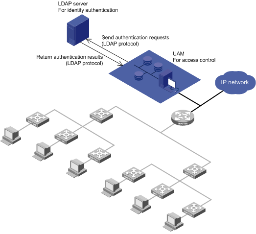
Features
LDAP authentication has the following features:
· After UAM receives an authentication request from an endpoint user, UAM forwards the request to the LDAP server using the LDAP protocol. The LDAP server authenticates the user identity.
· After the user passes identity authentication, UAM checks the binding information. If the user passes the check, UAM informs the access device to permit network access, and assigns access control policies to the access device. The access device then controls user access to the network according to the policies.
RSA authentication
Application scenarios
RSA authentication, shown in Figure 7, is used for applications (for example, bank systems) that use dynamic passwords for security. UAM does not support dynamic passwords. Because of this, a RADIUS server that supports dynamic passwords (such as an RSA server) must be deployed.
Figure 7 Network diagram of RSA authentication
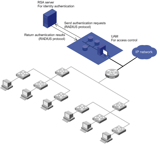
Features
RSA authentication has the following features:
· After UAM receives an authentication request from an endpoint user, UAM uses the RADIUS protocol to forward the request to the RSA server. The RSA server authenticates the user identity.
· After the user passes identity authentication, UAM checks the binding information. If the user passes the check, UAM tells the access device to permit network access, and assigns access control policies to the access device. The access device then controls user access to the network according to the policies.
Roaming authentication
Application scenarios
Roaming authentication is typically used in a large-scale network that has deployed multiple UAM servers. Each server performs access control in an area, and a user needs to access the network in different areas, as shown in Figure 8.
Figure 8 Network diagram of roaming authentication
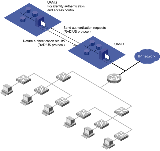
Example
In a roaming authentication scenario:
· Each endpoint user has a local UAM server, which is the server that saves the user's information.
· Each endpoint user also has a roaming UAM server, which is the server through which the user is connected to the network.
Assume that UAM 2 is the local UAM server of a user, and UAM 1 is the roaming UAM server of the user.
1. After UAM 1 receives an authentication request from the user, UAM 1 forwards the request to UAM 2 through the RADIUS protocol. UAM 2 authenticates the user identity.
2. If the user is valid, UAM 2 returns the authentication success message and the access control policies for the user to UAM 1. UAM 1 informs the access device to permit network access and to control network access according to the policies.
UAM and access device cooperation
An access device forwards packets between endpoint users and UAM. It controls user network access according to the policies assigned by UAM.
UAM supports establishing an authentication network with HP, H3C, Cisco, Huawei, and Ruijie devices, and with other devices that support standard RADIUS.
Access device configuration
For use with UAM, an access device must be configured with RADIUS, 802.1X, portal, VPN, MAC authentication, or certificates, as needed to meet the network requirements.
For more information about configuration, see the configuration guide of the access device.
Other UAM functions
Other UAM functions include monitoring and auditing, trouble report management, hierarchical management, system configuration, and self-service.
Monitoring and auditing
UAM monitors, controls, and audits access users.
Online user management
UAM displays all online users in a list. You can perform the following operations on the list:
· Send messages. For example, you can send a message to users, telling them to log off before system maintenance.
· Log off unauthorized online users.
· Log off users halted due to network device reboot or other reasons.
Access service topology display and operation
An access service topology integrates user management and access device management into the basic network topology.
On an access service topology, you can display/hide access users, log off online users, and send messages to online users.
Log management
Logs help you analyze and audit users' network access behaviors, as well as analyze and locate network errors.
UAM logs user authentication failures, user network access details, and user self-service operations.
Data export (dump)
The data export function lets you export data from UAM to other storage devices. Data export helps ensure high performance by implementing data backup and by reducing the data that UAM saves.
You can export UAM access user information and user network access details.
Reports
Reports summarize and display data in tables and charts. You can use the reports to audit user behavior history and to analyze trends.
UAM provides the following reports:
· Online user count
· Service report
· Idle account report
· Monthly account number report
· Authentication failure types report
· Offline reasons report
· Monthly/daily service usage report
· Monthly/daily per-user service usage report
UAM works with IAR to provide custom reports. You can create custom reports as needed.
User behavior audit in collaboration with UBA
UAM works with UBA to perform user behavior audits such as Web visiting audits, FTP audits, and mail audits. The combination of UAM and UBA offers operators tools for managing user access and authentication to critical network resources as well as visibility into the behavior of users on the network.
Wireless positioning in collaboration with WSM
UAM wireless positioning works with WSM to locate iNode clients using wireless access.
Terminal page customization
UAM offers a Web-based page editing tool that allows you to:
· Edit terminal pages based-on a predefined template.
· Edit terminal pages from the blank template.
· Edit terminal pages for PCs and tablets.
· Edit terminal pages for smartphones.
Terminal pages you can edit include:
· Portal page sets.
· Preregistration pages for users and guests.
· BYOD page sets.
· Self-Service Center login pages.
Trouble report management
The trouble report system is integrated in the Self-Service Center.
If access users encounter problems during network access, the trouble report function helps users and administrators solve problems as follows:
1. Access users can view the FAQ to find a solution.
2. If the solution is not in the FAQ, users can use the trouble report system to report unsolved problems to the administrator.
3. The administrator analyzes the problem and provides a solution, and if the problem is typical, adds it to the FAQ.
Hierarchical management
· The IMC platform supports hierarchical management of users and devices.
· UAM supports hierarchical management of services.
System configuration
The system configuration is a general policy for UAM operation.
The system configuration includes the following settings:
· Global parameter settings—Specify whether to enable the self-service and preregistration service, set the log storage period, and other global settings.
· Client secure configuration—Upgrade and maintain the iNode dictionary to prevent illegal clients from accessing the network.
Self service
At the UAM self-service center, access users can view and modify user information, view access details, modify user passwords, and clear online information.
UAM authentication architecture
UAM function in simple AAA authentication model
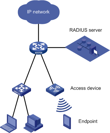
A simple AAA authentication model contains endpoints, access control methods, and authentication methods, as shown in Figure 9.
· Endpoint—A terminal device such as a laptop, desktop computer, tablet, and smartphone.
· Access control method—The access control method by the access device to control network access of each endpoint.
· Authentication method—The authentication method used by the RADIUS server (UAM) to verify the user identity.
Figure 9 Simple AAA authentication model
UAM authentication architecture description
Endpoint types
The UAM authentication architecture supports the following endpoint types:
· Smart device—Intelligent mobile phones and tablet computers.
· Regular terminal—PCs and laptops (collectively called PCs in this document).
· Mute terminal—IP phones and printers.
Access control methods
The UAM authentication architecture supports the following access control methods:
· Wired 802.1X authentication—Allows users who have passed 802.1X authentication to access the network.
· WLAN 802.1X authentication—Allows wireless users who have passed 802.1X authentication to access the network.
· Wired Portal authentication—Allows users who have passed portal authentication to access the network.
· WLAN Portal authentication—Allows wireless users who have passed portal authentication to access the network.
· SSL VPN authentication—Allows users (including wireless users) who have passed SSL VPN authentication to access the network.
· L2TP IPsec VPN authentication—Allows users (including wireless users) who have passed L2TP IPsec VPN authentication to access the network.
· Wired MAC authentication—Allows users who have passed MAC authentication to access the network.
· WLAN MAC authentication—Allows wireless users who have passed MAC authentication to access the network.
Authentication methods
The UAM authentication architecture supports the following authentication methods:
· Username/password authentication—Used to authenticate a user by user name and password. UAM local authentication, LDAP authentication, and RSA authentication support username/password authentication. In these authentication methods, UAM, the LDAP server, and the RSA server verify user names and passwords. For more information about LDAP authentication, see "Configuring portal authentication." For more information about RSA authentication, see "Configuring RSA authentication."
· Certificate authentication—Includes EAP-TLS, EAP-PEAP, and EAP-TTLS. You can configure the client to verify the server certificate. For more information about EAP-TLS, EAP-PEAP, and EAP-TTLS, see Table 1.
The following certificates are involved in certificate authentication:
¡ Client certificate—Certificate imported to the client. Only EAP-TLS requires client certificate.
¡ Server certificate—Certificate imported to the server.
¡ Client-side root certificate—Used to verify the server certificate.
¡ Server-side root certificate—Used to verify the client certificate.
Table 1 Certificate authentication
|
Certificate authentication |
Verify server certificate |
Authentication method |
UAM-side certificate |
Endpoint-side certificate |
|
EAP-TLS |
Yes |
User name + tunnel protection + mutual certificate authentication |
Root certificate + server certificate |
Root certificate + client certificate |
|
No |
User name + tunnel protection + client certificate authentication |
Root certificate + server certificate |
Client certificate |
|
|
EAP-PEAP (EAP-MD5, EAP-GTC, and EAP-MSCHAPv2) |
Yes |
User name/password + tunnel protection + server certificate authentication |
Server certificate |
Root certificate |
|
No |
User name/password + tunnel protection |
Server certificate |
None |
|
|
EAP-TTLS (EAP-MD5, EAP-GTC, EAP-MSCHAPv2, PPP MSCHAPv2, and PAP) |
Yes |
User name/password + tunnel protection + server certificate authentication |
Server certificate |
Root certificate |
|
No |
User name/password + tunnel protection |
Server certificate |
None |
For EAP-TLS, the following requirements must be met:
¡ The client certificate is imported to the endpoint.
¡ UAM has the root certificate for verifying the client certificate.
¡ The server certificate is imported to UAM for the encrypted tunnel establishment.
¡ If the client requires to verify the server certificate, you must import the root certificate to the endpoint.
For EAP-PEAP and EAP-TTLS, when the client requires to verify the server certificate, the endpoint and UAM do not authenticate each other by certificate. You only need to import the server certificate to UAM for the tunnel to secure the packets and user password exchanged during tunnel establishment.
· Username/password + pre-shared key authentication—Used in VPN authentication. In this authentication method, UAM authenticates a user by user name and password, and the access device authenticates the user by pre-shared key.
· Username/password + certificate authentication—Used in VPN authentication. In this authentication method, UAM authenticates a user by user name and password, and the endpoint and the access device authenticate each other by certificate.
· Transparent portal authentication—Typically used for smart devices. To pass Web page portal authentication for the first time, a user must input the correct user name and password. UAM obtains the user name and password and automatically performs UAM local authentication and LDAP authentication. In the two authentication methods, UAM and the LDAP server verify the user name and password. For more information about transparent portal authentication, see "Configuring transparent portal authentication."
· Anonymous MAC authentication—Used in MAC authentication. In this authentication method, UAM automatically performs authentication on an endpoint user without an account when the user attempts to connect to the network. When the user accesses the network through a browser, the user is redirected to the account registering page. This authentication method applies to visitors.
· Transparent MAC authentication—Used in MAC authentication. If the MAC address of an endpoint is bound with an account and enabled with transparent MAC authentication, the endpoint can always pass MAC address authentication. A user can bind a MAC address with an account in the Self-Service Center and enable transparent authentication on the MAC address. An operator can enable transparent authentication on MAC addresses in the endpoint MAC address list in UAM. For more information, see "Transparent MAC authentication."
· Mute terminal authentication—Used for mute terminals. UAM automatically processes a mute terminal's authentication requests.
Endpoint authentication schemes
UAM provides different authentication schemes for smart devices, PCs, and mute terminals.
Authentication schemes for smart devices
Smart devices include smart phones and tablets.
Table 2 describes the elements included in an authentication scheme for smart devices.
Authentication scheme element descriptions:
· The WLAN-802.1X access control method requires that smart device users pass 802.1X authentication to access the WLAN.
· The user name names and passwords are stored in both UAM and the LDAP server, but are verified only by the LDAP server. This authentication method is called LDAP authentication.
· The WLAN-Portal access control method requires that smart device users complete the WLAN configuration and then pass portal authentication before they can access the WLAN.
· Some LDAP servers (such as OpenLDAP) allow stored user passwords to be obtained by third-party systems, while others (Windows AD, for example) do not. LDAP server with readable passwords refers to an LDAP server from which UAM can obtain user passwords.
· The WLAN-MAC access control method requires that smart device users pass MAC authentication to access the WLAN.
· In RSA authentication, the RSA server verifies the user name and password for user login. Although UAM also stores the user name and password, it does not participate in the login verification.
Table 2 Authentication schemes for smart devices
|
Access control method |
Authentication method |
Credential transmission method |
Supported client |
Credential storage location |
|
WLAN-802.1X |
User name + mutual certificate authentication |
EAP-TLS |
Third-party client iNode MC (Android) |
User name: UAM. Root certificate: UAM and smart device. Client certificate: smart device. Server certificate: UAM. |
|
User name/password + server certificate authentication |
EAP-PEAP-MSCHAPv2 EAP-TTLS-MSCHAPv2 |
Third-party client |
User name/password: UAM and LDAP server. Root certificate: Smart device. Server certificate: UAM. |
|
|
WLAN-Portal |
Transparent portal authentication |
Proprietary protocol + PAP or CHAP |
Web browser |
The mappings among the MAC addresses, accounts, and access services are stored in UAM. |
|
User name/password |
PAP |
iNode MC Web browser |
User name/password: UAM and LDAP server. |
|
|
CHAP |
iNode MC Web browser |
User name/password: UAM and LDAP server with readable passwords. |
||
|
EAP-MD5 |
iNode MC |
User name/password: UAM and LDAP server with readable passwords. |
||
|
WLAN-MAC |
Transparent MAC authentication |
PAP CHAP EAP-MD5 |
None |
MAC address-account mappings: UAM. |
|
Anonymous MAC authentication |
PAP CHAP |
None |
MAC address-BYOD anonymous account mappings: UAM. |
|
|
SSL VPN |
User name/password |
PAP |
iNode MC |
User name/password: UAM, LDAP server, and RSA server. |
|
User name/password + client certificate authentication |
PAP + SSL |
iNode MC |
User name/password: UAM, LDAP server, and RSA server. Root certificate: SSL VPN gateway. Server certificate: SSL VPN gateway. Client certificate: Smart device. |
|
|
L2TP IPSec VPN |
Not supported |
Not supported |
Not supported |
Not supported |
Authentication schemes for PCs
PCs include desktop computers and laptops.
As described in Table 3, an authentication scheme for PCs includes the following elements: access control method, authentication method, credential transmission method, supported client, and credential storage location.
Authentication scheme element descriptions:
· The username name/password is stored in both UAM and the LDAP server but is verified only by the LDAP server. This authentication method is called LDAP authentication.
· The username name/password is stored in both UAM and the RSA server but is verified only by the RSA server. This authentication method is called RSA authentication.
· Some LDAP servers (such as OpenLDAP) allow stored user passwords to be obtained by third-party systems, while others (Windows AD, for example) do not. LDAP server with readable passwords refers to an LDAP server from which UAM can obtain user passwords.
· The WLAN-802.1X access control method requires that smart device users pass 802.1X authentication to access the WLAN.
· The WLAN-Portal access control method requires that smart device users complete the WLAN configuration and then pass portal authentication before they can access the WLAN.
· The WLAN-MAC access control method requires that smart device users must pass MAC authentication to access the WLAN.
· As a best practice, do not use third-party clients for L2TP IPsec VPN authentication.
Table 3 Authentication schemes for PCs
|
Access control method |
Authentication method |
Credential transmission method |
Supported client |
Credential storage location |
|
|
Wired-802.1X |
User name/password |
PAP |
iNode PC (any OS) Third-party client |
User name/password: UAM, LDAP server, or RSA server |
|
|
CHAP |
iNode PC (any OS) Third-party client |
User name/password: UAM or LDAP server with readable passwords |
|||
|
EAP-MD5 |
iNode PC (any OS) |
User name/password: UAM, LDAP server, or RSA server |
|||
|
Third-party client |
User name/password: UAM or LDAP server with readable passwords |
||||
|
User name + mutual certificate authentication |
EAP-TLS |
iNode PC (Windows) Third-party client |
User name: UAM Root certificate: UAM and PC Client certificate: PC Server certificate: UAM |
||
|
User name + client certificate authentication |
EAP-TLS |
iNode PC |
User name: UAM Root certificate: UAM Client certificate: PC Server certificate: UAM |
||
|
User name/password + server certificate authentication |
EAP-PEAP/EAP-MSCHAPv2 |
iNode PC (Windows) Third-party client |
User name/password: UAM or combination of AD + LDAP server with readable passwords Root certificate: PC Server certificate: UAM |
||
|
EAP-PEAP/EAP-GTC |
iNode PC (Windows) |
User name/password: UAM, LDAP server, or RSA server Root certificate: PC Server certificate: UAM |
|||
|
Third-party client |
User name/password: UAM or LDAP server Root certificate: PC Server certificate: UAM |
||||
|
EAP-PEAP/EAP-MD5 |
iNode PC (Windows) |
User name/password: UAM, LDAP server, or RSA server Root certificate: PC Server certificate: UAM |
|||
|
EAP-TTLS/EAP-MSCHAPv2 |
Third-party client |
User name/password: UAM or combination of AD + LDAP server with readable passwords Root certificate: PC Server certificate: UAM |
|||
|
EAP-TTLS/EAP-GTC |
Third-party client |
User name/password: UAM or LDAP server Root certificate: PC Server certificate: UAM |
|||
|
WLAN-802.1X |
User name + mutual certificate authentication |
EAP-TLS |
iNode PC (Windows) Third-party client |
User name: UAM Root certificate: UAM and PC Client certificate: PC Server certificate: UAM |
|
|
User name + client certificate authentication |
EAP-TLS |
iNode PC (Windows) |
User name: UAM Root certificate: UAM Client certificate: PC Server certificate: UAM |
||
|
User name/password + server certificate authentication |
EAP-PEAP/EAP-MSCHAPv2 |
iNode PC (Windows) Third-party client |
User name/password: UAM or combination of AD + LDAP server with readable passwords Root certificate: PC Server certificate: UAM |
||
|
EAP-PEAP/EAP-GTC |
iNode PC (Windows) |
User name/password: UAM, LDAP server, or RSA server Root certificate: PC Server certificate: UAM |
|||
|
Third-party client |
User name/password: UAM or LDAP server Root certificate: PC Server certificate: UAM |
||||
|
EAP-PEAP/EAP-MD5 |
iNode PC (Windows) |
User name/password: UAM, LDAP server, or RSA server Root certificate: PC Server certificate: UAM |
|||
|
EAP-TTLS/EAP-MSCHAPv2 |
iNode PC (Windows) Third-party client |
User name/password: UAM or combination of AD + LDAP server with readable passwords Root certificate: PC Server certificate: UAM |
|||
|
EAP-TTLS/EAP-GTC |
iNode PC (Windows) Third-party client |
User name/password: UAM or LDAP server Root certificate: PC Server certificate: UAM |
|||
|
Wired-Portal WLAN-Portal |
User name/password |
PAP |
iNode PC (any OS) iNode DC Web browser |
User name/password: UAM, LDAP server, or RSA server |
|
|
CHAP |
iNode PC (any OS) iNode DC Web browser |
User name/password: UAM or combination of AD + LDAP server with readable passwords |
|||
|
EAP-MD5 |
iNode PC (any OS) iNode DC |
User name/password: UAM, combination of AD + LDAP server with readable passwords, or RSA server |
|||
|
User name + mutual certificate authentication |
EAP-TLS |
iNode PC (Windows) |
User name: UAM Root certificate: UAM and PC Client certificate: PC Server certificate: UAM |
||
|
User name + client certificate authentication |
EAP-TLS |
iNode PC (Windows) |
User name: UAM Root certificate: UAM Client certificate: PC Server certificate: UAM |
||
|
User name/password + server certificate authentication |
EAP-PEAP/EAP-MSCHAPv2 |
iNode PC (Windows) |
User name/password: UAM or combination of AD + LDAP server with readable passwords Root certificate: PC Server certificate: UAM |
||
|
EAP-PEAP/EAP-GTC EAP-PEAP/EAP-DM5 |
iNode PC (Windows) |
User name/password: UAM, LDAP server, or RSA server Root certificate: PC Server certificate: UAM |
|||
|
Wired-MAC WLAN-MAC |
Transparent MAC authentication |
PAP CHAP EAP-MD5 |
None |
MAC address-account mappings: UAM |
|
|
Anonymous MAC authentication |
PAP CHAP |
None |
MAC address-BYOD anonymous account mappings: UAM |
||
|
SSL VPN |
User name/password |
PAP |
iNode PC |
User name/password: UAM, LDAP server, and RSA server |
|
|
User name/password + client certificate authentication |
PAP + SSL |
iNode PC |
User name/password: UAM, LDAP server, and RSA server Root certificate: SSL VPN gateway Server certificate: SSL VPN gateway Client certificate: PC |
||
|
L2TP IPsec VPN |
L2TP |
User name/password |
PAP |
iNode PC (Windows) Third-party client |
User name/password: UAM or LDAP server |
|
CHAP |
iNode PC (Windows) Third-party client |
User name/password: UAM or LDAP server with readable passwords |
|||
|
IPsec |
Pre-shared key |
IPsec |
iNode PC (Windows) Third-party client |
User name/password: VPN gateway |
|
|
Mutual certificate authentication between client and VPN gateway |
IPsec |
iNode PC (Windows) Third-party client |
Root certificate: PC and VPN gateway Device certificate: VPN gateway Client certificate: PC |
||
Authentication schemes for mute terminals
Mute terminals refer to terminals that cannot actively initiate authentication, such as IP phones and printers.
Table 4 Authentication schemes for mute terminals
|
Access control method |
Authentication method |
Credential transmission method |
Supported client |
Credential storage location |
|
Wired-MAC |
MAC authentication |
PAP CHAP EAP-MD5 |
None |
UAM |
Authentication priorities
Username/password authentication, transparent MAC authentication, and mute terminal authentication all can process authentication requests user names in MAC address format. To prevent conflicts, UAM determines authentication priorities in the following order from high to low:
· Mute terminal authentication.
· Transparent MAC authentication.
· Username/password authentication.
Transparent portal authentication does not cause authentication conflict because portal authentication processes the target MAC address before transparent portal authentication is performed.
BYOD
UAM supports Bring Your Own Device (BYOD), which allows you to apply different access policies to users in different access scenarios. An access scenario includes the following items:
· Access device
· SSID
· Vendor
· Type
· OS
· MAC address
UAM distinguishes between smart devices and PCs, employees and visitors, and laboratories and meeting rooms based on the access conditions.
BYOD is an indispensable part of UAM authentication architecture. As an internal processing mechanism, BYOD does not influence users' authentication operations. However, users may notice that the access privileges are tied to the scenarios.
For more information about BYOD, see "Configuring MAC/BYOD authentication."
Roaming
The roaming function is applicable to leagues, such as organization, company, and campus leagues.
You can use the roaming function together with 802.1X authentication, portal authentication, VPN authentication, or MAC authentication.
With roaming enabled, a user can access the network without losing the connection in a location other than the home location where the user was registered.
For more information about the roaming function, see "Configuring roaming authentication."
UAM authentication configuration guide
When you configure UAM authentication, use the following configuration restrictions and guidelines:
· Combinations of access control methods and authentication methods (for example, 802.1X authentication and username/password authentication) do not change along with the endpoint types.
· Certificate authentication, LDAP authentication, and RSA authentication require additional configuration based on UAM local authentication.
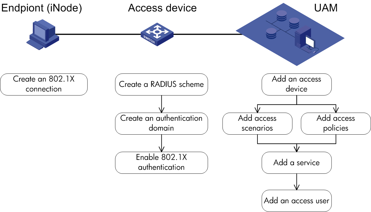
802.1X authentication and UAM local authentication
To implement 802.1X authentication and UAM local authentication, configure the following:
· UAM
· An access device
· The endpoint (iNode client)
Figure 10 Recommended configuration procedure
UAM configuration
To configure RADIUS authentication:
1. Configure the access device.
2. Configure the access scenario.
3. Configure an access policy.
4. Configure a service.
5. Configure an access user.
Configuring the access device
Access device configuration is required for configuring the device group of an access condition.
As a best practice, configure the access device first.
You must add the access device's information (such as the vendor name, IP address, port number, and key) to UAM, so UAM can exchange RADIUS packets with the access device during authentication.
To display the access device configuration page, click the User tab and select User Access Policy > Access Device Management > Access Device from the navigation tree, as shown in Figure 11.
For more configuration information, see "Configuring access devices."
Figure 11 Displaying the access device configuration page

Configuring the access condition
An access condition is the endpoint user's environment when the user accesses the network, including time, location, endpoint, network type, and other elements. UAM differentiates users based on the access conditions.
You need to configure the combination of the access condition and the access policy for a service.
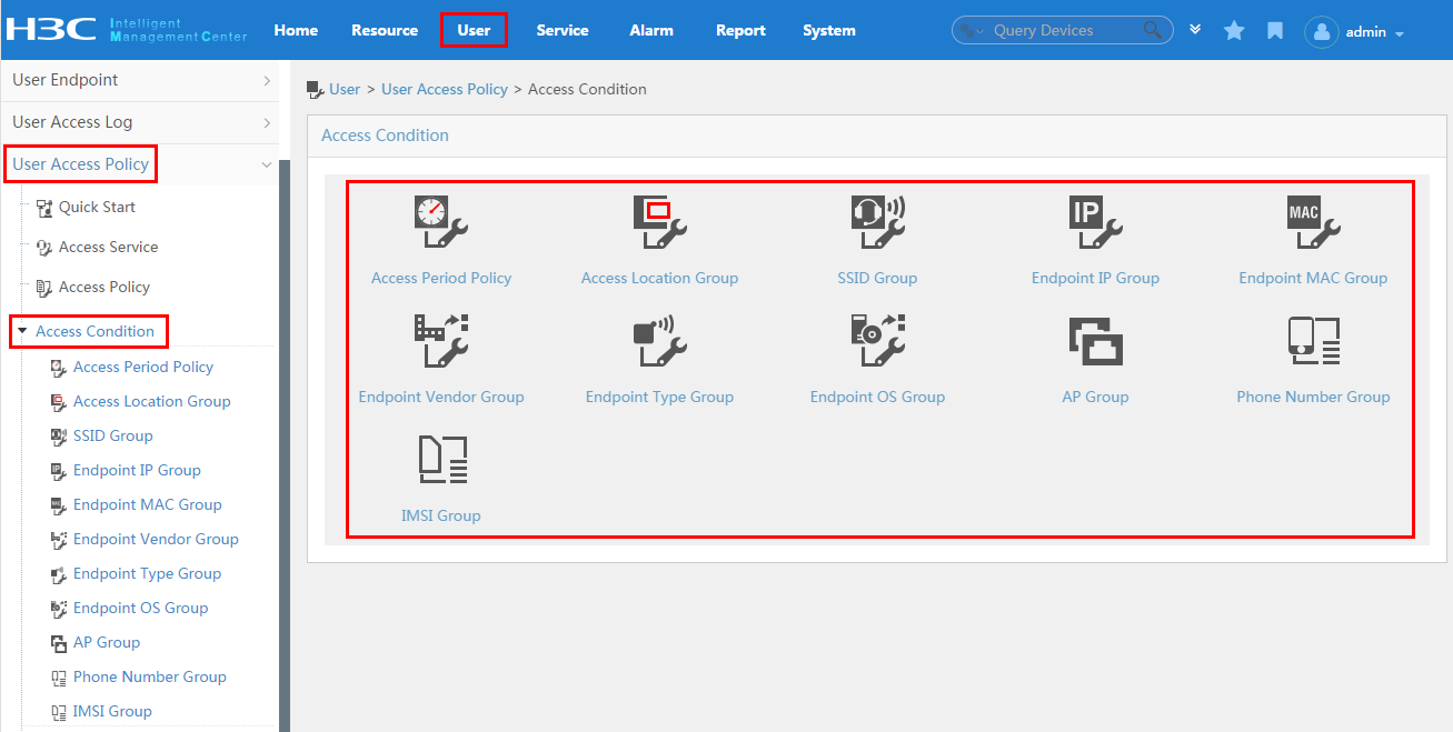
To display the access condition configuration page, click the User tab and select User Access Policy > Access Condition from the navigation tree, as shown in Figure 12.
The Access Condition area provides links to the configuration pages of the following information:
· Access period policy
· Access location group
· SSID group
· Endpoint IP group
· Endpoint MAC group
· Endpoint vendor group
· Endpoint type group
· Endpoint OS group
For more configuration information, see "Configuring access conditions."
Figure 12 Displaying the access condition configuration page
Configuring an access policy
An access policy is a set of control rules applied to endpoint users. UAM supports applying different access policies to users from different scenarios.
You need to configure the combination of the access condition and the access policy for a service.
An access policy includes:
· Access policy
· Security check
· Proprietary attribute assignment policy
Security check and Internet access control are available after you deploy the EAD component. For more information about security check and Internet access control, see HPE Intelligent Management Center v7.3 EAD Security Policy Administrator Guide.
To display the access policy configuration page, click the User tab and select User Access Policy > Access Policy from the navigation tree, as shown in Figure 13.
For more configuration information, see "Configuring access policies."
Figure 13 Displaying the access policy configuration page

To display the proprietary attribute configuration page, click the User tab and select User Access Policy > Access Device Management > Proprietary Attribute from the navigation tree, as shown in Figure 14.
For more configuration information, see "Configuring proprietary attribute assignment policies."
Figure 14 Displaying the proprietary attribute configuration page

Configuring a service
A service is a set of access policies applied in specific access conditions. You must add services before adding access users. When you add an access user, apply for a service for the user.
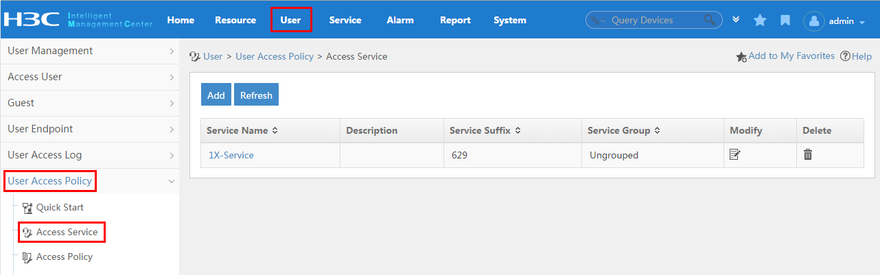
To display the service configuration page, click the User tab and select User Access Policy > Access Service from the navigation tree, as shown in Figure 15.
For more configuration information, see "Configuring access services."
Figure 15 Displaying the access service page

Configuring an access user
The configuration for an access user includes account, password, and service. When the access user is authenticated and online, the user is limited by the policies in the service.
To display the access user configuration page, click the User tab and select Access User > All Access Users from the navigation tree, as shown in Figure 16.
For more configuration information, see "Managing ordinary access users."
Figure 16 Displaying the access user configuration page

Access device configuration
For specific commands for each access device configuration item, see the access device configuration guide or command reference.
To configure the access device:
1. Create a RADIUS scheme.
2. Create a domain.
3. Enable 802.1X and configure the authentication protocol.
Creating a RADIUS scheme
An access device exchanges RADIUS packets with UAM according to the configured RADIUS scheme. When you configure a RADIUS scheme, follow these guidelines:
· You must specify the IP address of the UAM server as the authentication server IP and the accounting server IP in the RADIUS scheme.
Creating a domain
When you configure a domain, follow these guidelines:
· For 802.1X authentication, select LAN access as the endpoint access control method.
· The RADIUS scheme used by the domain must be configured as explained in "Creating a RADIUS scheme."
Enabling 802.1X and the password transport mode
Enable 802.1X globally and on interfaces.
HP Comware switches and H3C switches support PAP, CHAP, and EAP protocols. Cisco switches support only EAP.
Endpoint configuration
After you install the iNode client, create an 802.1X authentication connection. For the configuration procedure, see the iNode client help.
Parameter correlation
For authentication to run properly, the following must comply with the correlation rules listed in Table 5:
· The user name specified on the iNode client
· The domain and RADIUS scheme configuration on the access device
· The suffix of the service in UAM
As a best practice, use the configuration in the first line to accommodate authentication for terminal users.
The commands listed in Table 5 are HP Comware device commands. See the associated command reference manuals for other devices.
|
User name format on the iNode client |
Domain on the access device |
User name format configured on the access device |
Service suffix in UAM |
User name prefix conversion rule |
|
X@Y Y\X Y/X |
Y |
user-name-format with-domain |
Y |
Suffix |
|
user-name-format without-domain |
No suffix |
Delete |
||
|
X [Default Domain]\X [Default Domain]/X |
[Default Domain] The default domain specified on the access device |
user-name-format with-domain |
Name of the default domain |
Suffix |
|
user-name-format without-domain |
No suffix |
Delete |
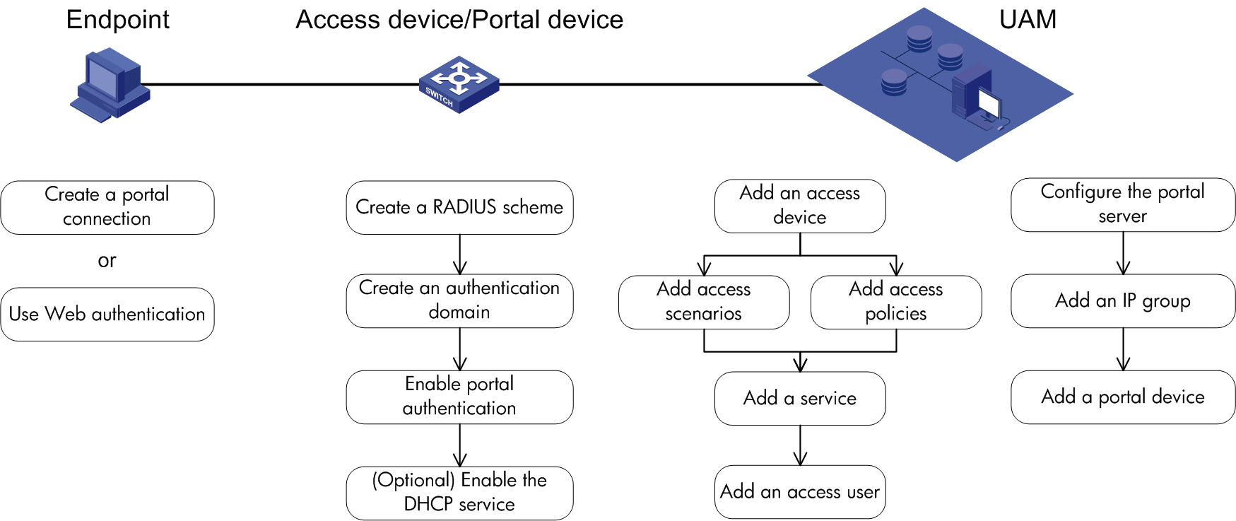
Portal authentication and UAM local authentication
To implement portal authentication and UAM local authentication, configure UAM, access device, and endpoint. Figure 17 lists the configuration tasks and the recommended configuration procedure.
Figure 17 Recommended configuration procedure
UAM configuration
UAM configuration includes RADIUS authentication configuration and portal authentication configuration.
Configuring RADIUS authentication
To configure RADIUS authentication:
1. Configure the access device.
2. Configure the access condition.
3. Configure an access policy.
4. Configure a service.
5. Configure an access user.
Configuring the access device
The access device configuration is required for configuring the access location group of an access condition.
As a best practice, configure the access device first.
You must add the access device's information (such as the vendor name, IP address, port number, and key) to UAM, so UAM can exchange RADIUS packets with the access device during authentication.
To display the access device configuration page, click the User tab and select User Access Policy > Access Device Management > Access Device from the navigation tree, as shown in Figure 18.
For more configuration information, see "Configuring access devices."
Figure 18 Displaying the access device configuration page

Configuring the access condition
An access condition is the endpoint user's environment when the user accesses the network, including time, location, endpoint, network type, and other elements. UAM distinguishes users based on the access conditions.
You need to configure the combination of the access condition and the access policy for a service.
To display the access condition configuration page, click the User tab and select User Access Policy > Access Condition from the navigation tree, as shown in Figure 19. The Access Condition area provides links to the configuration pages of the access policies and various groups. For more information, see "Configuring access conditions."
Figure 19 Displaying the access condition configuration page

Configuring an access policy
An access policy is a set of control rules applied to endpoint users. UAM supports applying different access policies to users from different access conditions.
You need to configure the combination of the access policy and the access condition for a service.
An access policy includes:
· Access policy
· Security check
· Proprietary attribute assignment policy
· Internet access control
Security check and Internet access control are available after you deploy the EAD component. For more information about security check and Internet access control, see HPE Intelligent Management Center v7.3 EAD Security Policy Administrator Guide.
To display the access policy configuration page, click the User tab and select User Access Policy > Access Policy from the navigation tree, as shown in Figure 20.
For more configuration information, see "Configuring access policies."
Figure 20 Displaying the access policy configuration page

To display the proprietary attribute configuration page, click the User tab and select User Access Policy > Access Device Management > Proprietary Attribute from the navigation tree, as shown in Figure 21.
For more configuration information, see "Configuring proprietary attribute assignment policies."
Figure 21 Displaying the proprietary attribute page

Configuring a service
A service is a set of access policies applied in specific access conditions. You must add services before adding access users. When you add an access user, apply for a service for the user.
To display the access service page, click the User tab and select User Access Policy > Access Service from the navigation tree, as shown in Figure 22.
For more configuration information, see "Configuring access services."
Figure 22 Displaying the access service page
Configuring an access user
The configuration for an access user includes account, password, and service. When the access user is authenticated and online, the user is limited by the policies in the service.
To display the access user configuration page, click the User tab and select Access User > All Access Users from the navigation tree, as shown in Figure 23.
For more configuration information, see "Managing ordinary access users."
Figure 23 Displaying the access user configuration page

Portal authentication
As a best practice, configure the portal access control method of UAM in the following order: configure the portal server, add an IP address group, and add a portal device.
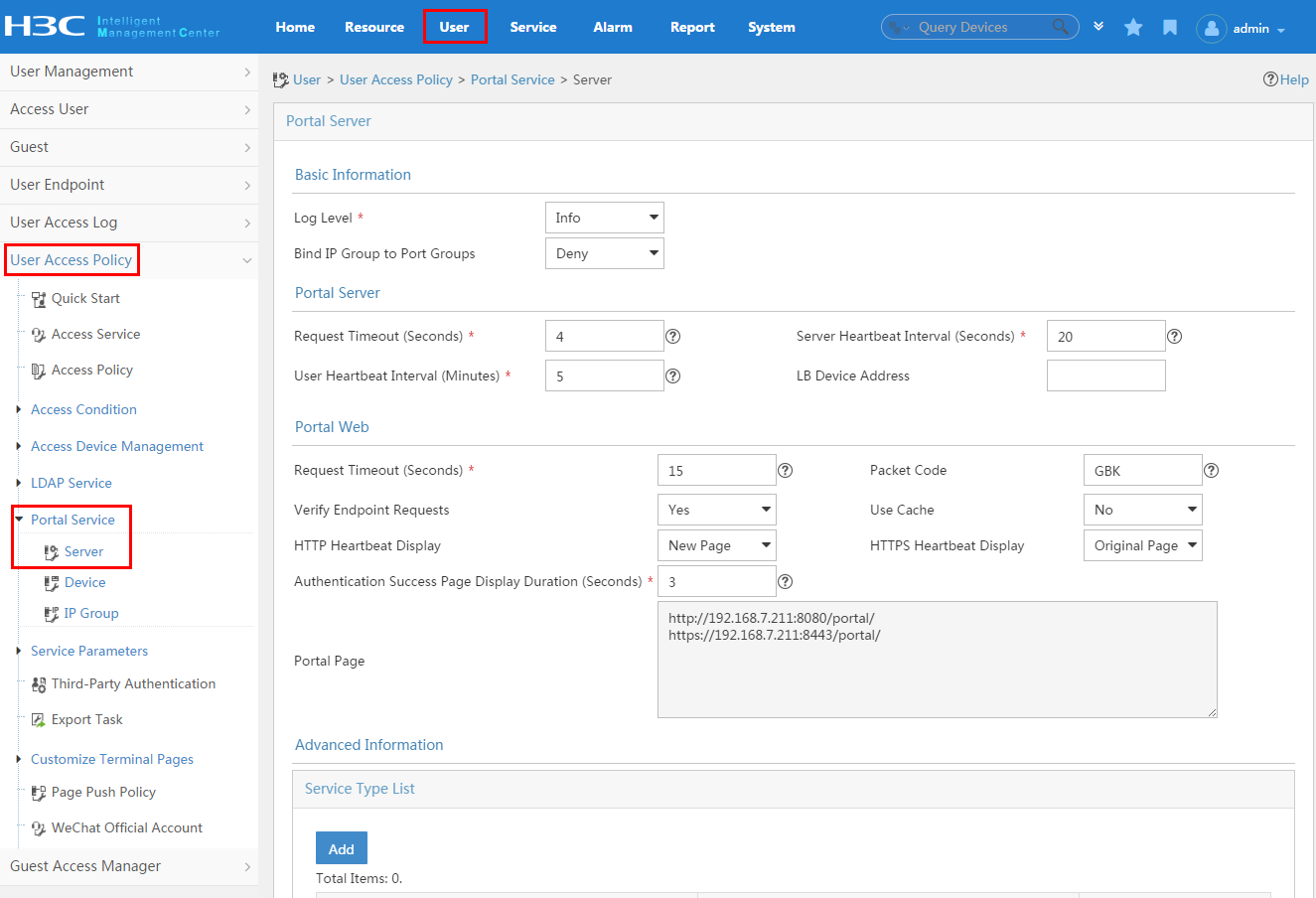
1. Configure the portal server parameters.
To display the portal server configuration page, click the User tab and select User Access Policy > Portal Service > Server from the navigation tree, as shown in Figure 24. For more configuration information, see "Configuring UAM as the portal server."
Figure 24 Displaying the portal server configuration page
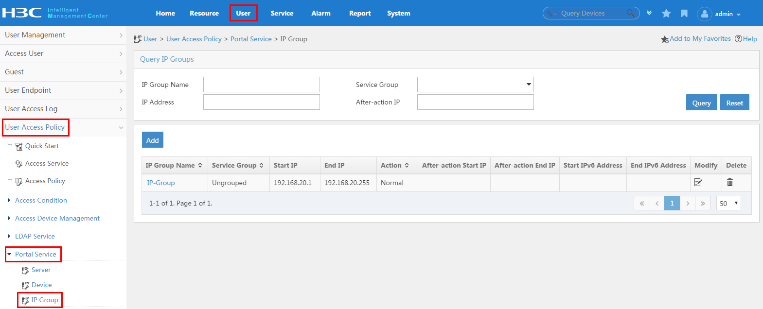
IP groups distinguish users. When you add the IP group, use the following guidelines:
¡ When you configure a portal device, you must reference an IP group.
¡ The portal device provides the portal service only for the users in the IP group.
¡ Add the IP group before adding the portal device.
3. To display the IP group configuration page, click the User tab, and then select User Access Policy > Portal Service > IP Group from the navigation tree, as shown in Figure 25. For more configuration information, see "Configuring IP address groups."
Figure 25 Displaying the IP group configuration page
4. Add a portal device and port group.
¡ You must add the portal device's information (such as the IP address, portal protocol version, listening port, and key) to UAM, so packets are properly exchanged between the portal server and the portal server during authentication.
¡ UAM uses port groups to control user accesses. Configure a port group for the target portal device after configuring the portal device.
¡ To display the portal device configuration page, click the User tab, and then select User Access Policy > Portal Service > Device from the navigation tree, as shown in Figure 26.
¡ To
display the port group configuration page, click the Port Group icon ![]() for a portal device
on the portal device configuration page. For more configuration information,
see "Configuring portal devices."
for a portal device
on the portal device configuration page. For more configuration information,
see "Configuring portal devices."
Figure 26 Displaying the portal device configuration page
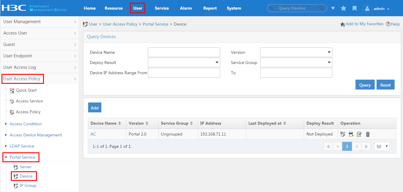
Figure 27 The port group configuration page

Access device configuration
For specific commands for each access device configuration item, see the access device configuration guide or command reference.
To configure the access device:
1. Create a RADIUS scheme.
2. Create a domain.
3. Enable portal authentication.
4. (Optional) Enable the DHCP service.
Creating a RADIUS scheme
An access device exchanges RADIUS packets with UAM according to the configured RADIUS scheme. When you configure a RADIUS scheme, follow these guidelines:
· The authentication server IP and the accounting server IP that you specified in the RADIUS scheme must be the IP address of the UAM server.
Creating a domain
When you configure a domain, follow these guidelines:
· Specify the access control method of endpoint users as portal authentication.
· The RADIUS scheme used by the domain must be configured as explained in the previous topic.
Enabling portal authentication
1. Configure the portal server, and specify the portal server IP address as the IP address of the UAM server.
2. Enable portal authentication on a Layer 3 Ethernet interface or VLAN interface.
Enabling the DHCP server
The DHCP service configuration is optional. Users also can use static IP addresses.
To enable the DHCP service:
1. Enable the DHCP service.
2. Configure the IP address pool and gateway.
Endpoint configuration
You can directly perform portal authentication when you access the network through the browser on the endpoint. After you install the iNode client, you can also create a portal authentication connection to perform portal authentication. For the configuration procedure, see the iNode client help.
To use the security check or Internet access control function, you must install the iNode client to perform portal authentication.
Parameter correlation
For authentication to be performed properly, the user name specified on the iNode client, the domain and RADIUS scheme configuration on the access device, and the suffix of the service in UAM must comply with the correlation rule, as described in Table 6.
|
User name format on the iNode client |
Domain on the access device |
User name format configured on the access device |
Service suffix in UAM |
|
X@Y |
Y |
user-name-format with-domain |
Y |
|
user-name-format without-domain |
No suffix |
||
|
X |
[Default Domain] The default domain specified on the access device |
user-name-format with-domain |
Name of the default domain |
|
user-name-format without-domain |
No suffix |
Users can access the network from different locations using different services. These services are differentiated by the use of different service suffixes. For endpoint users who are accessing the network from different locations, use the configuration in the first line as a best practice.
The commands listed in Table 6 are HP Comware device commands. See the associated command reference manuals for other devices.
Transparent portal authentication
Transparent portal authentication simplifies the portal authentication process for smart endpoint devices such as smartphones.
The workflow of transparent portal authentication is as follows:
1. After an account successfully accesses the network through the portal login page on an endpoint device, the portal server stores the endpoint MAC address, access user account, and access service if the following requirements are met:
¡ The access user account can be bound with endpoint devices for transparent authentication, and the number of endpoint devices bound with the account has not exceeded the upper limit (specified by Max. Smart Device Bindings for Portal).
¡ The service assigned to the account is enabled with the Transparent Authentication on Portal Endpoints option.
¡ The port group used by the endpoint device for authentication is configured to support transparent authentication.
¡ The HTTP user agent of the endpoint device matches a transparent authentication character.
2. Next time the endpoint device attempts to access the network, the portal gateway and portal server use the access user account mapped to the endpoint MAC address and automatically perform portal authentication for the endpoint device. In this process, UAM does not display the portal login page or require the user name and password to be provided.
Transparent portal authentication is a special portal authentication. To configure transparent portal authentication, you must perform the following configurations on UAM, access device, and endpoint besides the configurations described in "Portal authentication and UAM local authentication."
UAM configuration
1. Add the HTTP user agent character of the endpoint as a transparent authentication character:
a. Click the User tab.
b. From the navigation tree, select User Endpoint > Endpoint Profiling.
c. Click the HTTP User Agent tab. UAM predefines a large number of HTTP user agents.
d. Click Add to add a new HTTP user agent.
Figure 28 Adding an HTTP user agent for transparent portal users
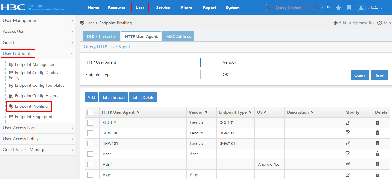
2. Enable transparent authentication on a service.
When adding a service, select Transparent Authentication, as shown in Figure 29.
Figure 29 Enabling transparent portal authentication for a service
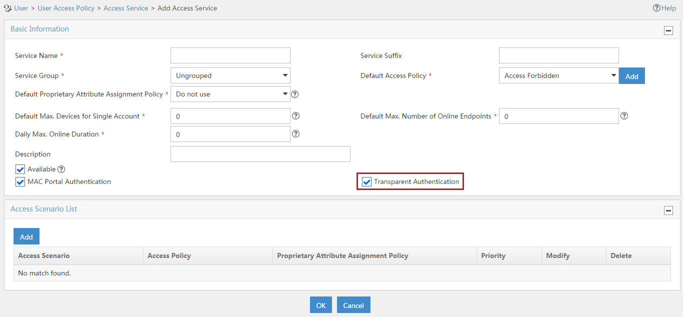
3. Enable transparent authentication on a portal port group.
When adding a port group, select Supported for Transparent Authentication, as shown in Figure 30.
Figure 30 Enabling transparent authentication on a portal port group
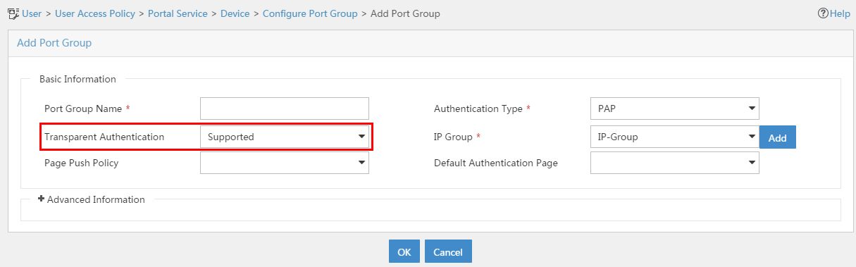
4. Enable transparent authentication in system parameters.
On the User Endpoint Settings page, select Enable for the Transparent Authentication field, as shown in Figure 31. To enable transparent authentication on non-smart devices, select Permit for the Non-Smart Device Transparent Portal AuthN field.
Figure 31 Enabling transparent authentication in user endpoint settings
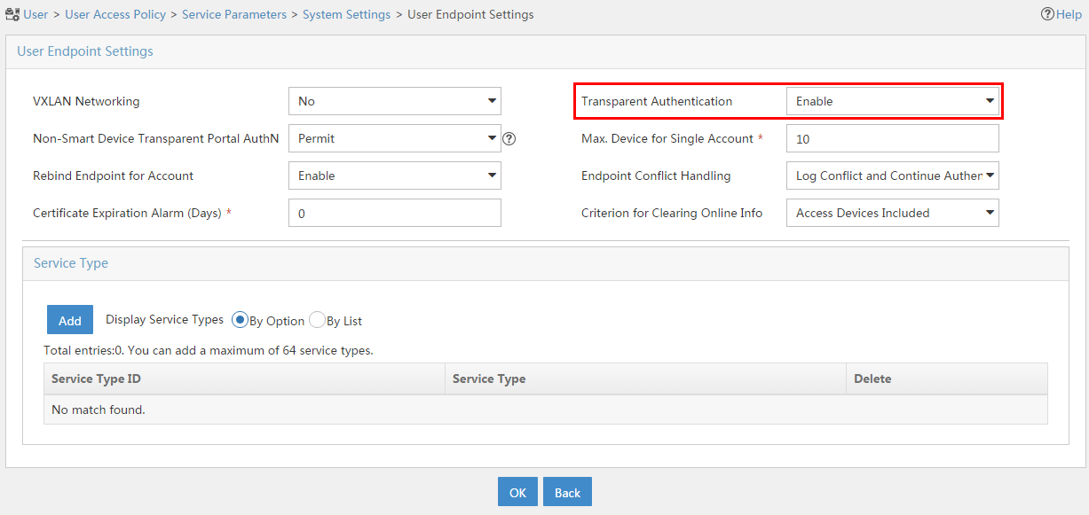
Access device configuration
Enable the MAC-triggered access control method on the access device. For example, to enable this function on an HP Comware device, execute the following commands:
· In system view, execute the portal mac-trigger server ip ip-address command. The ip-address argument specifies the portal server by its IP address.
· In interface view, execute the portal mac-trigger enable command.
Endpoint configuration
When a user uses an endpoint to access the network for the first time, the endpoint must pass Web page portal authentication. After a successful authentication, the portal server automatically authenticates the endpoint when the user uses the endpoint to access the network.
Anonymous MAC authentication
In this authentication method, UAM automatically authenticates endpoint users without accounts and allows the users to access the network with limited privileges.
When a user attempts to access an unauthorized network through a browser, the user is redirected to the account registering page.
With an account, the user can pass the authentication to get full privileges to access the network. Anonymous MAC authentication applies to visitors.
To configure this authentication method, you must configure UAM, DHCP server, access device, and endpoint, as shown in Figure 32.
Figure 32 Recommended configuration procedure
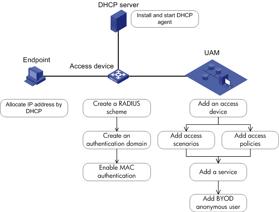
UAM configuration
This configuration is similar to the configuration described in "UAM configuration." The differences are as follows:
· In a service, UAM uses the access policy assigned to a user's matching access condition to control the user access to the network. Therefore, if you apply anonymous MAC authentication to users, you must take users' access privileges into account when configuring the access condition, access policy, and service.
· When adding an access user, add a BYOD anonymous account for all endpoint users without accounts, as shown in Figure 33.
Figure 33 Adding the BYOD anonymous account
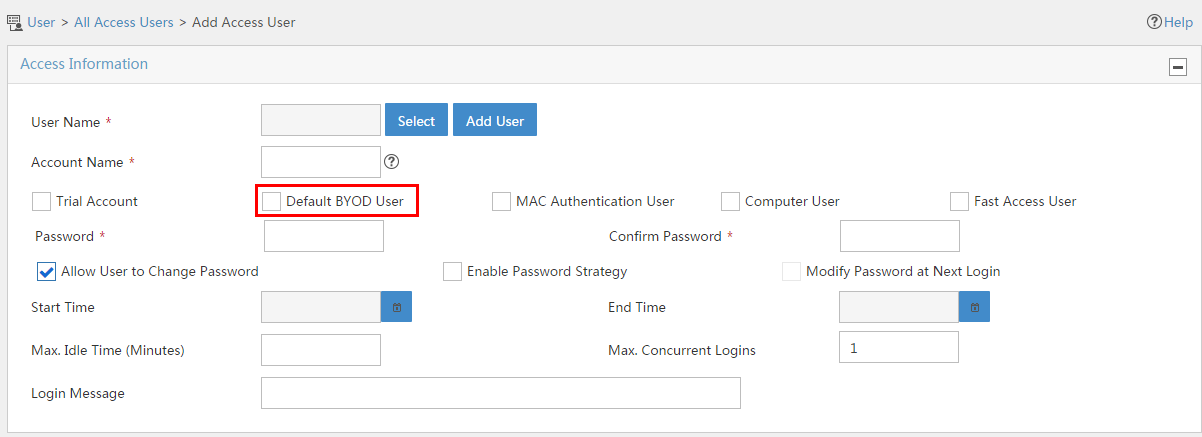
Anonymous MAC authentication is not available when:
· The MAC address of the endpoint has been bound with an existing account. You can view the MAC address-to-account bindings in the endpoint device address list. To view the endpoint list, click the User tab and select User Endpoint > Endpoint Management from the navigation tree.
· The MAC address of the endpoint is in the MAC address range of the mute terminals in UAM.
· The MAC address of the endpoint is the same as an existing user name in UAM.
DHCP server configuration
Install and enable DHCP agent. For information about the installation, see HP IMC deployment guides.
Access device configuration
For specific commands for each access device configuration item, see the access device configuration guide or command reference.
To configure the access device:
1. Create a RADIUS scheme.
2. Create a domain.
3. Enable MAC address authentication.
Creating a RADIUS scheme
An access device exchanges RADIUS packets with UAM according to the configured RADIUS scheme. When you configure a RADIUS scheme, follow these guidelines:
· The authentication server IP and the accounting server IP that you specified in the RADIUS scheme must be the IP address of the UAM server.
· The shared key and authentication/accounting port specified in the RADIUS scheme must be consistent with those configured for the access device on UAM.
Creating a domain
When you configure a domain, follow these guidelines:
· For MAC authentication, select LAN access as the endpoint access control method.
· The RADIUS scheme used by the domain must be configured as explained in the previous topic.
Enabling MAC address authentication
1. Enable MAC address authentication globally and on an interface.
2. Specify the domain created in the previous step for MAC address authentication.
Endpoint configuration
The endpoint must use DHCP to obtain its IP address.
If the endpoint is configured with a static IP address, or the endpoint uses a browser to access the network by the IP address rather than the domain name of the network, the endpoint cannot be redirected to the account registering page.
Account registering configuration
After passing anonymous MAC authentication, a user who uses a browser to access the network with domain name is redirected to the account registering page, as shown in Figure 34.
Figure 34 Account registering page
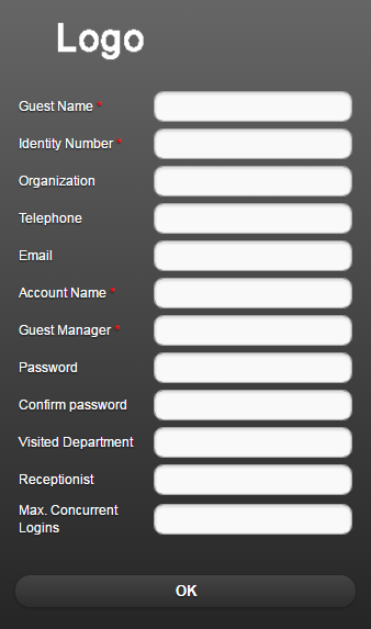
To register an account:
1. Select Register a New User from the Access Method list.
2. Enter the account name, password, user name, and the ID number in the corresponding fields. Enter the password again in the Confirm password field to confirm the password.
3. Select the manager for the account from the Manager list. Options include all existing managers in UAM.
4. Enter the department to visit and the receptionist in the Visited Department and Receptionist fields.
5. Click Register Guest.
¡ If the guest auto-registration function is enabled in UAM, UAM assigns the guest auto-registration service to the account that is successfully registered, and the guest can pass transparent MAC authentication. For more information about transparent MAC authentication, see "Transparent MAC authentication."
¡ If the guest auto-registration function is disabled in UAM, the manager examines and approves the account and assigns a service to the account. For more information about visitor management, see "Managing guests."
Transparent MAC authentication
This transparent authentication method is based on MAC addresses. With this authentication method enabled, UAM automatically authenticates an endpoint as soon as the endpoint is trying to connect to the network.
To implement transparent MAC authentication, you must configure UAM and the access device.
UAM configuration
In addition to the UAM configuration described in "802.1X authentication and UAM local authentication," you must perform the following tasks:
· Enable transparent authentication on access services. For more information about the configuration details, see Figure 29.
· Enable transparent authentication in UAM. For more information about the configuration details, see "Configuring user endpoint settings."
· Enable transparent authentication for a specific endpoint device.
To enable transparent authentication for a specific endpoint device, use the following methods:
· Enable transparent authentication in UAM with operator privileges.
This method applies to the endpoint devices whose MAC addresses UAM already obtains.
a. To access the endpoint device address list page, click the User tab and select User Endpoint > Endpoint Management from the navigation tree.
b. Select target endpoint devices and click Enable Transparent Authentication.
Figure 35 Enabling transparent authentication with operator privileges
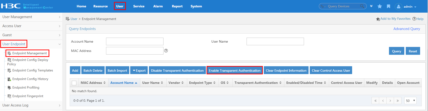
· Enable transparent authentication in the Self-Service Center.
a. From the navigation tree, select Endpoint Management > Endpoint List.
b. Select target MAC addresses and click Enable Transparent Authentication. If the target MAC addresses are not in the list, you can first add them to the list. Each MAC address in the list is bound with an access user.
The results for the operations of adding endpoint devices, deleting endpoint devices, and changing transparent authentication status on endpoint devices are synchronized to the endpoint device address list in UAM.
Figure 36 Enabling transparent authentication in the Self-Service Center
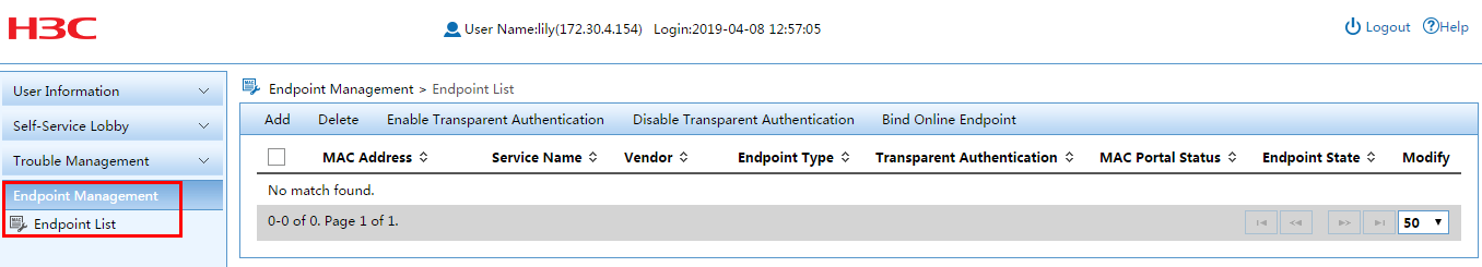
· After a user passes anonymous MAC authentication, UAM automatically performs transparent authentication on the user when the user registers an account.
For more information about anonymous MAC authentication, see "Anonymous MAC authentication."
Access device configuration
For specific commands for each access device configuration item, see the access device configuration guide or command reference.
To configure the access device:
1. Create a RADIUS scheme.
2. Create a domain.
3. Enable MAC address authentication.
Creating a RADIUS scheme
An access device exchanges RADIUS packets with UAM according to the configured RADIUS scheme. When you configure a RADIUS scheme, follow these guidelines:
· The authentication server IP and the accounting server IP that you specified in the RADIUS scheme must be the IP address of the UAM server.
· The shared key and authentication/accounting port specified in the RADIUS scheme must be consistent with those configured for the access device on UAM.
Creating a domain
When you configure a domain, follow these guidelines:
· For MAC authentication, select LAN access as the endpoint user access control method.
· The RADIUS scheme used by the domain must be configured as explained in the previous topic.
Enabling MAC address authentication
1. Enable MAC address authentication globally and on an interface.
2. Specify the domain created in the previous step for MAC address authentication.
VPN authentication and UAM local authentication
To implement VPN authentication and UAM local authentication, you must configure UAM, VPN gateway, and iNode client (PC). Figure 37 shows the configuration items and the recommended configuration procedure.
Figure 37 Recommended configuration procedure
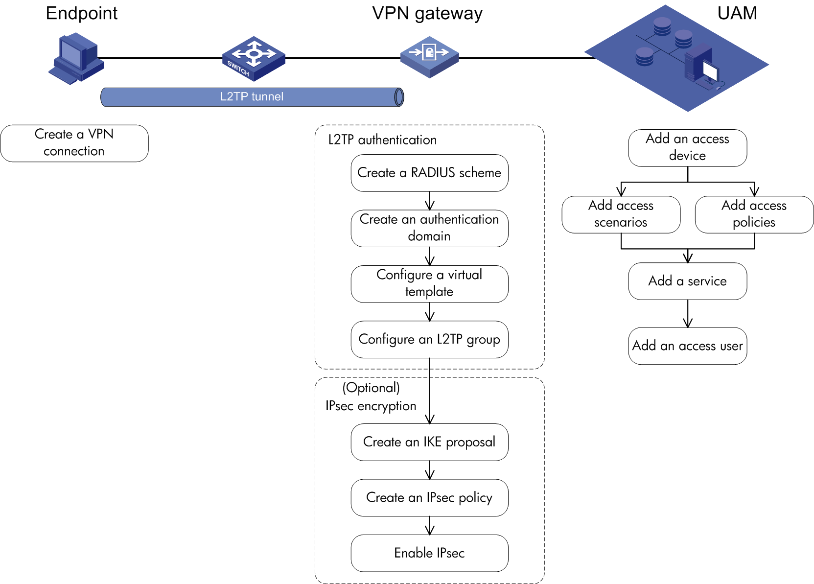
UAM configuration
To configure RADIUS authentication:
1. Configure the access device.
2. Configure the access condition.
3. Configure an access policy.
4. Configure a service.
5. Configure an access user.
Configuring the access device
Access device configuration is a prerequisite for configuring the access location group of an access condition. As a best practice, configure the access device first.
You must add the access device's information (such as the vendor name, IP address, port number, and key) to UAM, so UAM can exchange RADIUS packets with the access device during authentication.
To display the access device configuration page, click the User tab and select User Access Policy > Access Device Management > Access Device from the navigation tree, as shown in Figure 38.
For more configuration information, see "Configuring access devices."
Figure 38 Displaying the access device configuration page

Configuring the access condition
An access condition is the endpoint user's environment when the user accesses the network, including time, location, endpoint, network type, and other elements. UAM differentiates users based on the access conditions.
You need to configure a combination of the access condition and the access policy for a service. Therefore, you must configure the access condition.
To display the access condition configuration page, click the User tab and select User Access Policy > Access Condition from the navigation tree, as shown in Figure 39.
The Access Condition area provides links to the configuration pages of the following information:
· Access period policy
· Access location group
· SSID group
· Endpoint IP group
· Endpoint MAC group
· Endpoint vendor group
· Endpoint type group
· Endpoint OS group
For more configuration information, see "Configuring access conditions."
Figure 39 Displaying the access condition configuration page

Configuring an access policy
An access policy refers to a set of control rules applied to endpoint users. UAM supports applying different access policies to users from different access conditions.
You need to configure a combination of the access condition and the access policy for a service. Therefore, you must configure the access policy.
An access policy includes:
· Access policy
· Security check
· Proprietary attribute assignment policy
· Internet access control
Security check and Internet access control are available after you deploy the EAD component. For more information about security check and Internet access control, see HPE Intelligent Management Center v7.3 EAD Security Policy Administrator Guide.
To display the access policy configuration page, click the User tab and select User Access Policy > Access Policy from the navigation tree, as shown in Figure 40.
For more configuration information, see "Configuring access policies."
Figure 40 Displaying the access policy configuration page

To display the proprietary attribute configuration page, click the User tab and select User Access Policy > Access Device Management > Proprietary Attribute from the navigation tree, as shown in Figure 41.
For more configuration information, see "Configuring proprietary attribute assignment policies."
Figure 41 Displaying the proprietary attribute configuration page

Configuring a service
A service is a set of access policies applied in specific access conditions. You must add services before adding access users. When you add an access user, apply for a service for the user.
To display the access service page, click the User tab and select User Access Policy > Access Service from the navigation tree, as shown in Figure 42.
For more configuration information, see "Configuring access services."
Figure 42 Displaying the access service page

Configuring an access user
The configuration for an access user includes account, password, and service. When the access user is authenticated and online, the user is limited by the policies in the service.
To display the access user configuration page, click the User tab and select Access User > All Access Users from the navigation tree, as shown in Figure 43.
For more configuration information, see "Managing ordinary access users."
Figure 43 Displaying the access user configuration page

VPN gateway configuration
To configure the VPN gateway:
1. Configure the L2TP authentication.
2. (Optional) Configure IPsec encryption.
Configuring L2TP authentication
1. Create a RADIUS scheme.
A VPN gateway exchanges RADIUS packets with UAM according to the configured RADIUS scheme. When you configure a RADIUS scheme, follow these guidelines:
¡ The authentication server IP and the accounting server IP, specified in the RADIUS scheme, must be the IP address of the UAM server.
¡ The shared key and authentication/accounting port specified in the RADIUS scheme must be consistent with those configured for the access device on UAM.
2. Create a domain.
When you configure a domain, follow these guidelines:
¡ Specify the access mode as ppp access for endpoint users.
¡ The RADIUS scheme used by the domain must be configured as explained in the previous topic.
3. Configure a virtual template.
One end of an L2TP tunnel is the VPN virtual adapter on the PC, and the other end of the L2TP tunnel is the virtual template configured on the VPN gateway.
When you configure a virtual template, you must specify these parameters:
¡ Authentication method and domain for VPN users.
¡ IP address of the virtual template.
¡ IP address pool for VPN users. The IP address pool must be in the same subnet as the virtual template's IP address. If existing IP address pools do not follow this requirement, you must configure a proper IP address pool before configuring the virtual template.
4. Configure an L2TP group.
Enable the L2TP function and configure an L2TP group. When you configure an L2TP group, you must specify these parameters:
¡ The virtual template used to respond VPN user authentication requests. (Specify the virtual template configured in the previous step.)
¡ The L2TP tunnel's name and password.
(Optional) Configuring IPsec encryption
1. Create an IKE proposal.
You can create multiple IKE proposals at each end of an L2TP tunnel. The L2TP tunnel can be set up as along as one IKE proposal matches the proposal of a remote end.
When you create an IKE proposal, follow these guidelines:
¡ The negotiation mode selected for the VPN gateway must be consistent with that selected for the iNode client. The negotiation modes that the VPN gateway can select include pre-shared key and certificate.
¡ To make sure an IKE proposal at one tunnel end matches one on the other end, the VPN gateway must select the parameters that the iNode client supports. Take pre-shared key as an example. You can specify only MD5 or SHA as the authentication algorithm, DES-CBC or 3DES-CBC as the encryption algorithm, and group1 or group 2 as the DH group.
2. Create an IPsec policy.
An IPsec policy can be configured manually or through IKE negotiation. The IKE negotiation mode is used as an example.
In IKE negotiation mode, you only need to create an IPsec policy, and reference an existing IKE peer, IPsec proposal, and ACL. Table 7 lists the detailed configuration.
Table 7 Configuring an IPsec policy through IKE negotiation
|
Configuration item |
Sub-item |
Description |
|
|
IKE peer |
Negotiation mode |
Main mode or aggressive mode. |
|
|
Negotiation ID type |
IP address in main mode, IP address or name in aggressive mode. |
||
|
Peer IP |
IP address range of the peer. It must include the iNode client's IP address, because only clients in this IP address range can perform IKE negotiation. |
||
|
Authentication method |
Configure a pre-shared key or a PKI domain according to the authentication method (pre-shared key or digital signature authentication) configured in the IKE proposal. |
||
|
IPsec proposal |
Encapsulation mode |
Tunnel mode or transport mode. Usually, the tunnel mode is used. |
Check the support of the iNode client for these parameters. Make sure the configuration is consistent on the VPN gateway and the iNode client. |
|
Security protocol |
AH or ESP. AH supports only authentication algorithms. ESP supports both authentication and encryption algorithms. |
||
|
Authentication algorithm |
AH supports MD5 and SHA. ESP supports MD5 and SHA. |
||
|
Encryption algorithm |
AH does not support encryption algorithms. ESP supports DES and 3DES. |
||
|
ACL |
N/A |
Use the ACL to identify the data flows to be protected by IPsec. |
|
|
IPsec policy |
N/A |
Reference the configured IKE peer, IPsec proposal, and ACL in the IPsec policy. |
|
3. Enable IPsec.
Enable IPsec on the interface connected to the iNode client.
Command reference
The following information provides an example for the L2TP IPsec VPN authentication configuration commands on the VPN gateway. The commands can vary on your device.
[VPNgateway] radius scheme vpn
[VPNgateway-radius-vpn] primary authentication 192.168.20.105 1812
[VPNgateway-radius-vpn] primary accounting 192.168.20.105 1813
[VPNgateway-radius-vpn] key authentication hello
[VPNgateway-radius-vpn] key accounting hello
[VPNgateway-radius-vpn] server-type extended
[VPNgateway-radius-vpn] user-name-format with-domain
[VPNgateway-radius-vpn] quit
[VPNgateway] domain vpn
[VPNgateway-isp-vpn] authentication ppp radius-scheme vpn
[VPNgateway-isp-vpn] authorization ppp radius-scheme vpn
[VPNgateway-isp-vpn] accounting ppp radius-scheme vpn
[VPNgateway-isp-vpn] ip pool 1 200.1.1.2 200.1.1.31
[VPNgateway-isp-vpn] quit
[VPNgateway] interface virtual-template 1
[VPNgateway-Virtual-Template1] ppp authentication-mode chap domain vpn
[VPNgateway-Virtual-Template1] ip address 200.1.1.1 255.255.255.0
[VPNgateway-Virtual-Template1] remote address pool 1
[VPNgateway-Virtual-Template1] quit
[VPNgateway] l2tp enable
[VPNgateway] l2tp-group 1
[VPNgateway-l2tp1] allow l2tp virtual-template 1 remote inode
[VPNgateway-l2tp1] tunnel password simple 111111
[VPNgateway-l2tp1] quit
[VPNgateway] ike proposal 1
[VPNgateway-ike-proposal-1] authentication-method pre-share
[VPNgateway-ike-proposal-1] authentication-algorithm md5
[VPNgateway-ike-proposal-1] encryption-algorithm des-cbc
[VPNgateway-ike-proposal-1] dh group1
[VPNgateway-ike-proposal-1] sa duration 86400
[VPNgateway-ike-proposal-1] quit
[VPNgateway] ike peer vpnpeer
[VPNgateway-ike-peer-vpnpeer] exchange-mode main
[VPNgateway-ike-peer-vpnpeer] id-type ip
[VPNgateway-ike-peer-vpnpeer] remote-address 100.1.1.200 100.1.1.250
[VPNgateway-ike-peer-vpnpeer] pre-shared-key simple 123
[VPNgateway-ike-peer-vpnpeer] nat traversal
[VPNgateway-ike-peer-vpnpeer] quit
[VPNgateway] ipsec proposal vpnpro
[VPNgateway-ipsec-proposal-vpnpro] encapsulation-mode tunnel
[VPNgateway-ipsec-proposal-vpnpro] transform ah
[VPNgateway-ipsec-proposal-vpnpro] ah authentication-algorithm md5
[VPNgateway-ipsec-proposal-vpnpro] quit
[VPNgateway] acl number 3000
[VPNgateway-acl-adv-3000] rule 0 permit ip
[VPNgateway-acl-adv-3000] quit
[VPNgateway] ipsec policy vpnpolicy 1 isakmp
[VPNgateway-ipsec-policy-isakmp-vpnpolicy-1] ike-peer vpnpeer
[VPNgateway-ipsec-policy-isakmp-vpnpolicy-1] proposal vpnpro
[VPNgateway-ipsec-policy-isakmp-vpnpolicy-1] security acl 3000
[VPNgateway-ipsec-policy-isakmp-vpnpolicy-1] pfs dh-group1
[VPNgateway-ipsec-policy-isakmp-vpnpolicy-1] quit
[VPNgateway] interface GigabitEthernet 0/1
[VPNgateway-GigabitEthernet0/1] ipsec policy vpnpolicy
Endpoint configuration
After a user installs the iNode client, the user needs to create an L2TP IPsec VPN authentication connection.
The parameters configured on the iNode client must be consistent with those configured on the VPN gateway.
Parameter correlation
For authentication to be performed properly, the following items must comply with the correlation rule listed in Table 8:
· The user name specified on the iNode client.
· The domain, RADIUS scheme, and the virtual template configuration on the VPN gateway.
· The suffix of the service in UAM.
The commands listed in Table 8 are HP Comware device commands. See the associated command reference manuals for other devices.
|
User name format on the iNode client |
VPN gateway configuration |
Service suffix in UAM |
|
X@Y or X |
RADIUS scheme: user-name-format with-domain Domain name: Y Virtual template: ppp authentication chap domain Y |
Y |
Mute terminal authentication
Mute terminals refer to the network terminals with an authentication process that cannot be manually triggered. Common mute terminals include IP phones and printers.
Mute terminal authentication is an automatic authentication to allow mute terminals to access the network.
To implement mute terminal authentication, you must configure UAM and the access device. Figure 44 shows the configuration items and the recommended configuration procedure.
Figure 44 Recommended configuration procedure
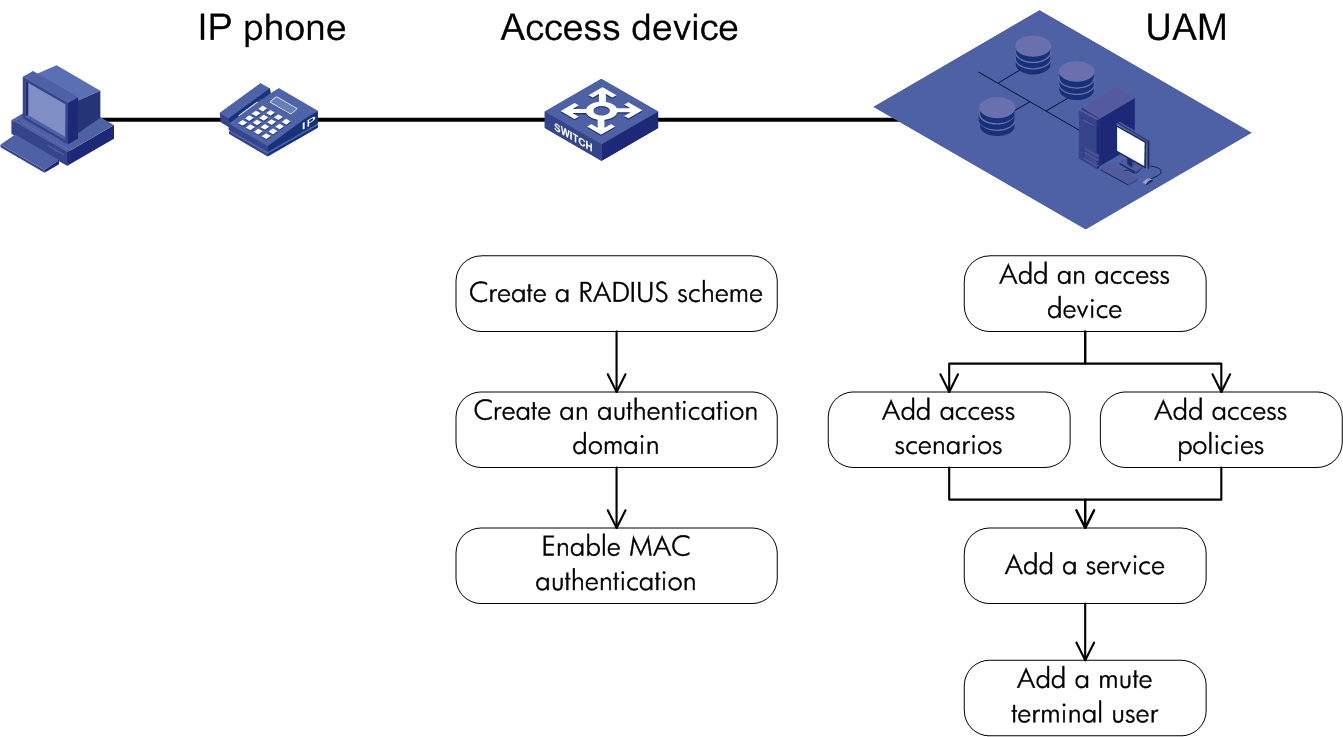
UAM configuration
To configure RADIUS authentication:
1. Configure the access device.
2. Configure the access condition.
3. Configure an access policy.
4. Configure a service.
5. Configure a mute terminal user.
Configuring the access device
Access device configuration is a prerequisite for configuring the access location group of an access condition. As a best practice, configure the access device first.
You must add the access device's information (such as the vendor name, IP address, port number, and key) to UAM, so UAM can exchange RADIUS packets with the access device during authentication.
To display the access device configuration page, click the User tab and select User Access Policy > Access Device Management > Access Device from the navigation tree, as shown in Figure 45. For more configuration information, see "Configuring access devices."
Figure 45 Displaying the access device configuration page

Configuring the access condition
An access condition is the endpoint user's environment when the user accesses the network, including time, location, endpoint, network type, and other elements. UAM differentiates users based on the access conditions.
You need to configure a combination of the access condition and the access policy for a service. Therefore, you must configure the access condition.
To display the access condition configuration page, click the User tab and select User Access Policy > Access Condition from the navigation tree, as shown in Figure 46.
The Access Condition area provides links to the configuration pages of the following information:
· Access period policy
· Access location group
· SSID group
· Endpoint IP group
· Endpoint MAC group
· Endpoint vendor group
· Endpoint type group
· Endpoint OS group
For more configuration information, see "Configuring access conditions."
Figure 46 Displaying the access condition configuration page

Configuring an access policy
An access policy refers to a set of control rules applied to endpoint users. UAM supports applying different access policies to users from different scenarios.
You need to configure a combination of the access condition and the access policy for a service. Therefore, you must configure the access policy.
An access policy includes:
· Access policy
· Security check
· Proprietary attribute assignment policy
· Internet access control
Security check and Internet access control are available after you deploy the EAD component. For more information about security check and Internet access control, see HPE Intelligent Management Center v7.3 EAD Security Policy Administrator Guide.
To display the access policy configuration page, click the User tab and select User Access Policy > Access Policy from the navigation tree, as shown in Figure 47.
For more configuration information, see "Configuring access policies."
Figure 47 Displaying the access policy configuration page
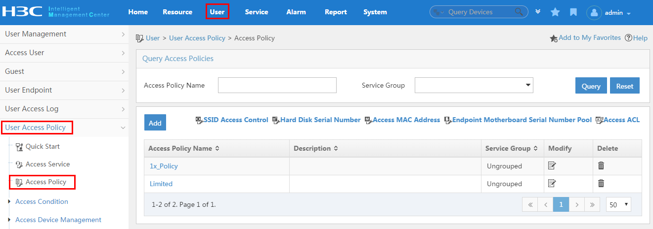
To display the proprietary attribute configuration page, click the User tab and select User Access Policy > Access Device Management > Proprietary Attribute from the navigation tree, as shown in Figure 48.
For more configuration information, see "Configuring proprietary attribute assignment policies."
Figure 48 Displaying the proprietary attribute configuration page
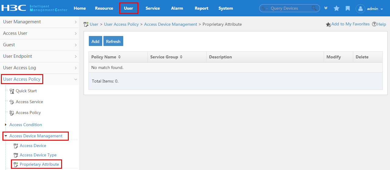
Configuring a service
A service is a set of access policies applied in specific access conditions. You must add services before adding access users. When you add an access user, apply for a service for the user.
To display the access service page, click the User tab and select User Access Policy > Access Service from the navigation tree, as shown in Figure 49. For more configuration information, see "Configuring access services."
Figure 49 Displaying the access service page

Configuring a mute terminal user
You cannot directly configure a mute terminal as a mute terminal user. Instead, you can configure a MAC address range. When a mute terminal has a MAC address that is within the MAC address range accesses the network, UAM automatically generates a mute terminal user.
To display the mute terminal user configuration page, click the User tab and select Access User > Mute Terminal User from the navigation tree, as shown in Figure 50.
For more configuration information, see "Managing mute terminal users."
Figure 50 Displaying the mute terminal user configuration page
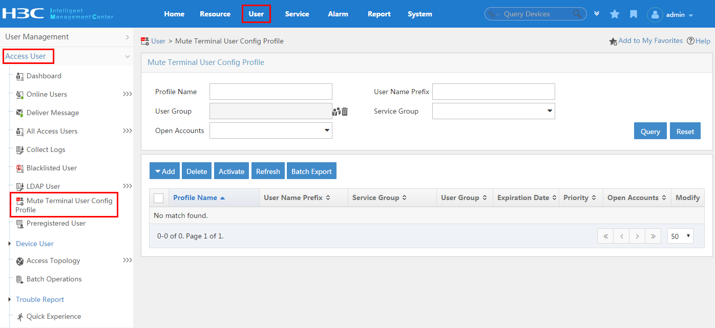
Access device configuration
For specific commands for each access device configuration item, see the access device configuration guide or command reference.
To configure the access device:
1. Create a RADIUS scheme.
2. Create a domain.
3. Enable MAC address authentication.
Creating a RADIUS scheme
An access device exchanges RADIUS packets with UAM according to the configured RADIUS scheme. When you configure a RADIUS scheme, follow these guidelines:
· The authentication server IP and the accounting server IP that you specified in the RADIUS scheme must be the IP address of the UAM server.
Creating a domain
When you configure a domain, follow these guidelines:
· For MAC authentication, select LAN access as the endpoint access control method.
· The RADIUS scheme used by the domain must be configured as explained in "Creating a RADIUS scheme."
Enabling MAC address authentication
1. Enable MAC address authentication globally and on an interface.
2. Specify the domain created in the previous step for MAC address authentication.
Mute terminal configuration
No configuration is needed on a mute terminal.
LDAP authentication
In LDAP authentication, the LDAP server authenticates user identity. The combinations of LDAP authentication and an access control method include:
· 802.1X authentication and LDAP authentication
· Portal authentication and LDAP authentication
· VPN authentication and LDAP authentication
For these authentication combinations, the access device configuration on the endpoint configuration are the same as those described in "802.1X authentication and UAM local authentication," "Portal authentication and UAM local authentication," and "VPN authentication and UAM local authentication." See Figure 51 for an example of the configuration on UAM for LDAP authentication.
Figure 51 Recommended configuration procedure
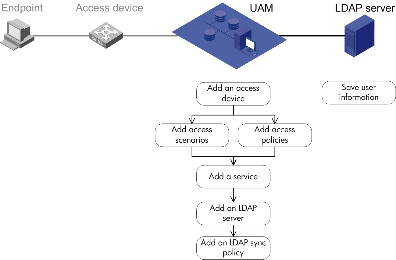
UAM configuration
To configure RADIUS authentication and LDAP server collaboration:
1. Configure the access device.
2. Configure the access condition.
3. Configure the access policy.
4. Configure a service.
5. Configure the LDAP server.
6. Configure an LDAP synchronization policy.
Configuring the access device
Access device configuration is a prerequisite for configuring the access location group of an access condition. As a best practice, configure the access device first.
You must add the access device's information (such as the vendor name, IP address, port number, and key) to UAM, so UAM can exchange RADIUS packets with the access device during authentication.
To display the access device configuration page, click the User tab and select User Access Policy > Access Device Management > Access Device from the navigation tree, as shown in Figure 52.
For more configuration information, see "Configuring access devices."
Figure 52 Displaying the access device configuration page
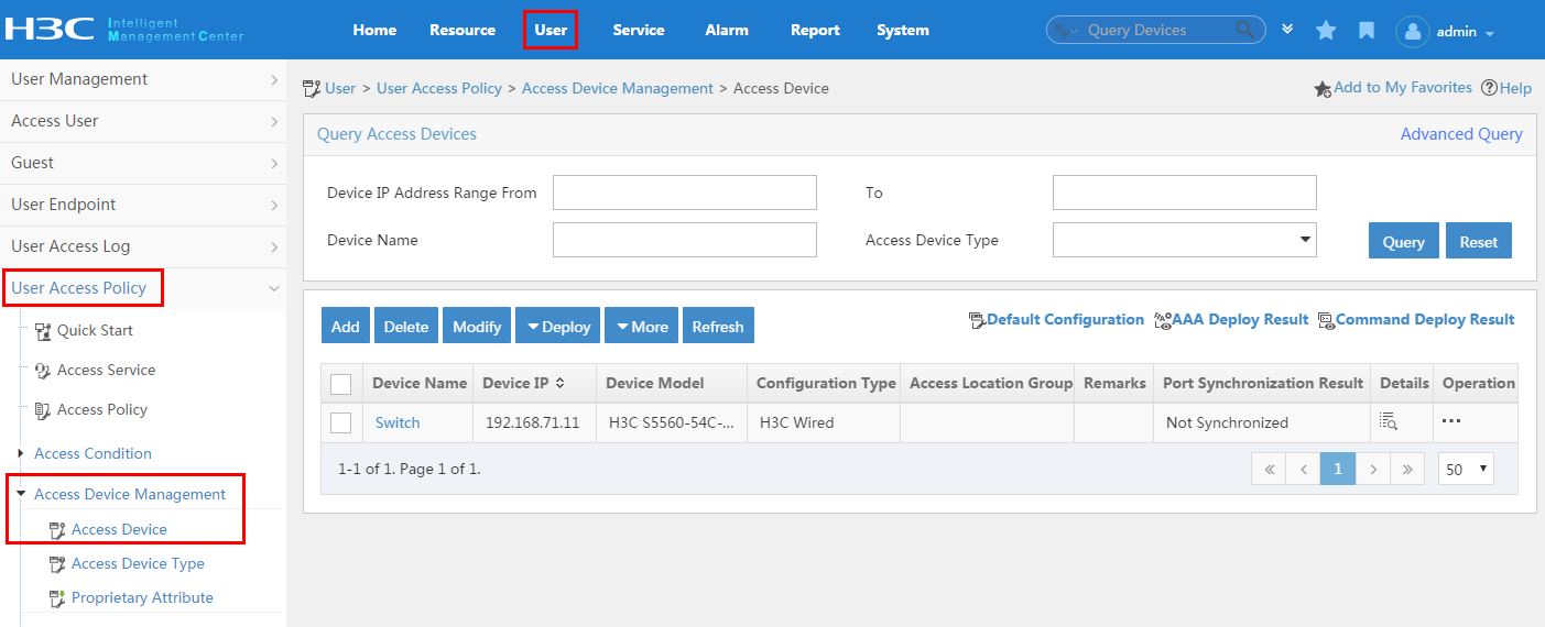
Configuring the access condition
An access condition is the endpoint user's environment when the user accesses the network, including time, location, endpoint, network type, and other elements. UAM differentiates users based on the access conditions.
You need to configure a combination of the access condition and the access policy for a service. Therefore, you must configure the access condition.
To display the access condition configuration page, click the User tab and select User Access Policy > Access Condition from the navigation tree, as shown in Figure 53.
The Access Condition area provides links to the configuration pages of the following information:
· Access period policy
· Access location group
· SSID group
· Endpoint IP group
· Endpoint MAC group
· Endpoint vendor group
· Endpoint type group
· Endpoint OS group
For more configuration information, see "Configuring access conditions."
Figure 53 Displaying the access condition configuration page

Configuring an access policy
An access policy refers to a set of control rules applied to endpoint users. UAM supports applying different access policies to users from different scenarios.
You need to configure the combination of the access policy and the access condition for a service. Therefore, you must configure the access policy.
An access policy includes:
· Access policy
· Security check
· Proprietary attribute assignment policy
· Internet access control
Security check and Internet access control are available after you deploy the EAD component. For more information about security check and Internet access control, see HPE Intelligent Management Center v7.3 EAD Security Policy Administrator Guide.
To display the access policy configuration page, click the User tab and select User Access Policy > Access Policy from the navigation tree, as shown in Figure 54.
For more configuration information, see "Configuring access policies."
Figure 54 Displaying the access policy configuration page

To display the proprietary attribute configuration page, click the User tab and select User Access Policy > Access Device Management > Proprietary Attribute from the navigation tree, as shown in Figure 55.
For more configuration information, see "Configuring proprietary attribute assignment policies."
Figure 55 Displaying the proprietary attribute configuration page

Configuring a service
A service is a set of access policies applied in specific access conditions. You must add services before adding access users. When you add an access user, apply for a service for the user.
To display the access service page, click the User tab and select User Access Policy > Access Service from the navigation tree, as shown in Figure 56.
For more configuration information, see "Configuring access services."
Figure 56 Displaying the access service page

Configuring the LDAP server
Add an LDAP server to allow UAM to read data from the LDAP server.
To display the LDAP server configuration page, click the User tab and select User Access Policy > LDAP Service > LDAP Server from the navigation tree, as shown in Figure 57.
For more configuration information, see "Managing LDAP servers."
Figure 57 Displaying the LDAP server configuration page
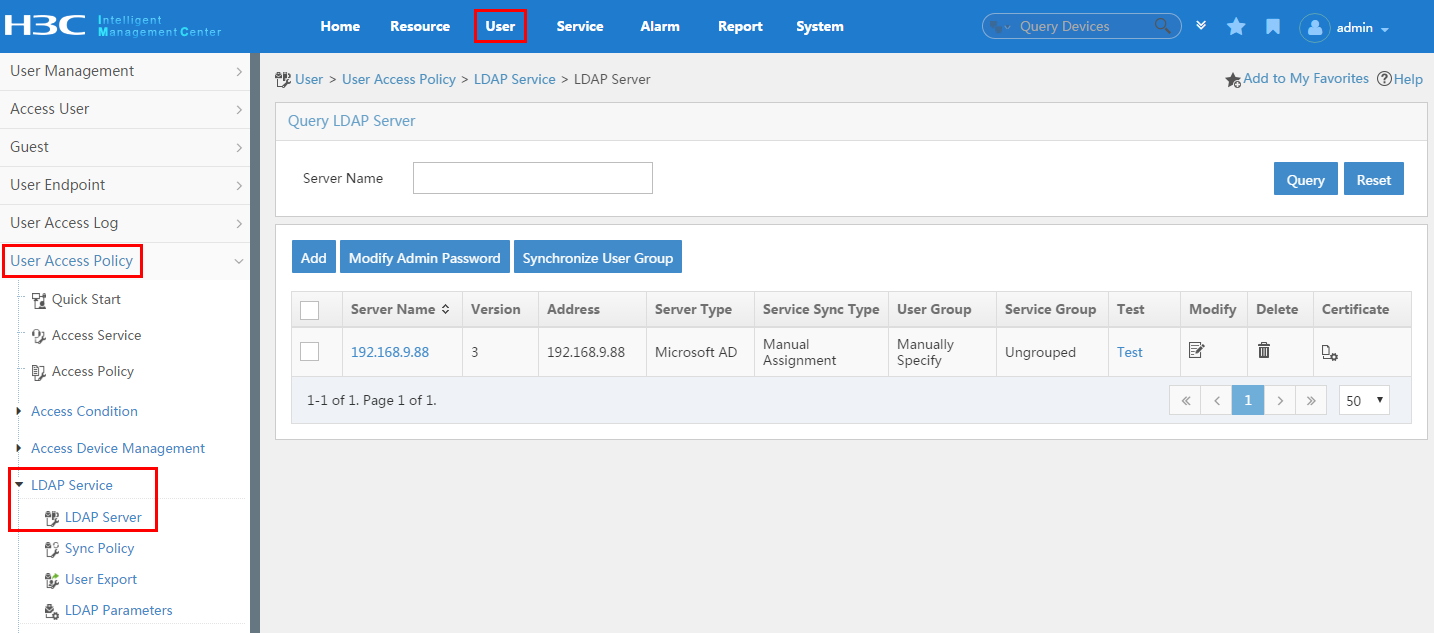
Configuring an LDAP synchronization policy
Create an LDAP synchronization policy to allow UAM to synchronize user data from the LDAP server according to the policy.
To display the LDAP synchronization policy configuration page, click the User tab and select User Access Policy > LDAP Service > Sync Policy from the navigation tree, as shown in Figure 58.
Figure 58 Displaying the LDAP synchronization policy configuration page
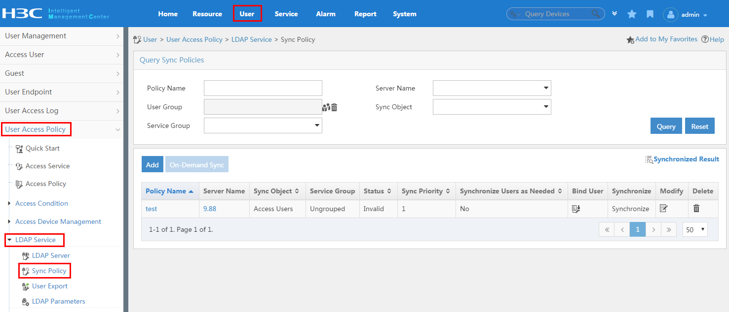
RSA authentication
In RSA authentication, UAM forwards user authentication requests to the RSA server. RAS authenticates user identity. The combinations of RSA authentication and an access control method include:
· 802.1X authentication and RSA authentication
· Portal authentication and RSA authentication
· VPN authentication and RSA authentication
For these authentication combinations, the access device configuration on the iNode client configuration are the same as those described in "802.1X authentication and UAM local authentication," "Portal authentication and UAM local authentication," and "VPN authentication and UAM local authentication." See Figure 59 for an example of the configuration on UAM for RSA authentication.
Figure 59 Recommended configuration procedure
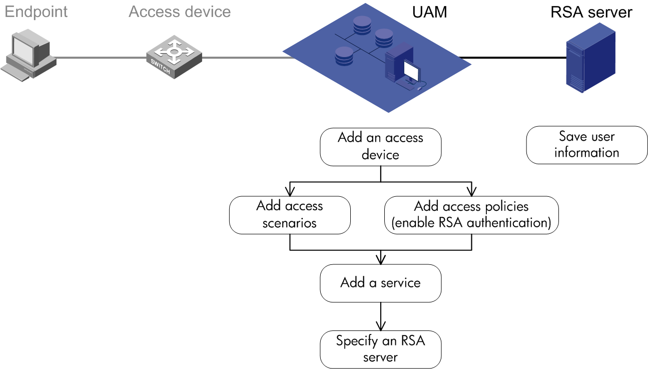
UAM configuration
To configure RADIUS authentication and RSA server collaboration:
1. Configure the access device.
2. Configure the access condition.
3. Configure the access policy.
4. Configure a service.
5. Specify an RSA server.
Configuring the access device
Access device configuration is a prerequisite for configuring the access location group of an access condition. As a best practice, configure the access device first.
You must add the access device's information (such as the vendor name, IP address, port number, and key) to UAM, so UAM can exchange RADIUS packets with the access device during authentication.
To display the access device configuration page, click the User tab and select User Access Policy > Access Device Management > Access Device from the navigation tree, as shown in Figure 60.
For more configuration information, see "Configuring access devices."
Figure 60 Displaying the access device configuration page

Configuring the access condition
An access condition is the endpoint user's environment when the user accesses the network, including time, location, endpoint, network type, and other elements. UAM differentiates users based on the access conditions.
You need to configure a combination of the access condition and the access policy for a service. Therefore, you must configure the access condition.
To display the access condition configuration page, click the User tab and select User Access Policy > Access Condition from the navigation tree, as shown in Figure 61.
The Access Condition area provides links to the configuration pages of the following information:
· Access period policy
· Access location group
· SSID group
· Endpoint IP group
· Endpoint MAC group
· Endpoint vendor group
· Endpoint type group
· Endpoint OS group
For more configuration information, see "Configuring access conditions."
Figure 61 Displaying the access condition configuration page

Configuring an access policy
An access policy refers to a set of control rules applied to endpoint users. UAM supports applying different access policies to users from different scenarios.
You need to configure the combination of the access policy and the access condition for a service. Therefore, you must configure the access policy.
An access policy includes:
· Access policy
· Security check
· Proprietary attribute assignment policy
· Internet access control
Security check and Internet access control are available after you deploy the EAD component. For more information about security check and Internet access control, see HPE Intelligent Management Center v7.3 EAD Security Policy Administrator Guide.
To display the access policy configuration page, click the User tab and select User Access Policy > Access Policy from the navigation tree, as shown in Figure 62.
For more configuration information, see "Configuring access policies."
Figure 62 Displaying the access policy configuration page

To display the proprietary attribute configuration page, click the User tab and select User Access Policy > Access Device Management > Proprietary Attribute from the navigation tree, as shown in Figure 63.
For more configuration information, see "Configuring proprietary attribute assignment policies."
Figure 63 Displaying the proprietary attribute configuration page

Configuring a service
A service is a set of access policies applied in specific access conditions. You must add services before adding access users. When you add an access user, apply for a service for the user.
To display the service configuration page, click the User tab and select User Access Policy > Access Service from the navigation tree, as shown in Figure 64.
For more configuration information, see "Configuring access services."
Figure 64 Displaying the access service page

Specifying an RSA server
When UAM receives an authentication request from a user, it checks whether the third-party authentication function is enabled. If yes, UAM forwards the authentication request to the RSA server. The RSA server determines whether the user passes authentication.
To specify an RSA server:
1. Click the User tab.
2. From the navigation tree, select User Access Policy > Third-Party Authentication.
3. Click the Configure icon ![]() for the third-party
authentication policy to display the third-party authentication configuration page, as shown in Figure 65.
for the third-party
authentication policy to display the third-party authentication configuration page, as shown in Figure 65.
Figure 65 Third-party authentication configuration page
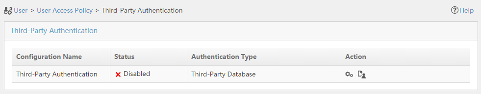
4. Enable the third-party authentication and specify an RSA server. For more configuration information, see "Configuring RSA authentication."
Certificate authentication
Certificate authentication is an identity authentication with high security. It is used by a client and a server (IMC UAM) to authenticate validity of each other.
802.1X authentication and portal authentication support certificate authentication.
802.1X authentication and certificate authentication
To use certificate authentication, adjust the configuration for 802.1X authentication and UAM local authentication.
Importing the root certificate and server certificate to UAM
To import certificates to UAM, click the User tab and select User Access Policy > Service Parameters > Certificate from the navigation tree to display the certificate configuration page, as shown in Figure 66.
For more configuration information, see "Configuring certificate authentication."
Figure 66 Displaying the certificate configuration page
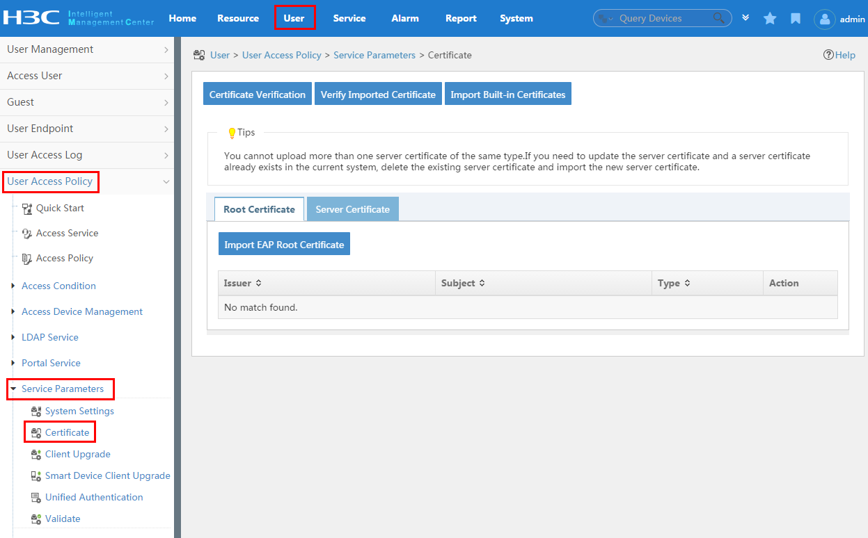
Configuring a preferred EAP type when adding an access policy
1. To display the access policy configuration page, click the User tab and select User Access Policy > Access Policy from the navigation tree.
2. Click Add to add an access policy. As shown in Figure 67, select a preferred EAP authentication type and a subtype for the access policy.
For other configurations for the access policy, see "Configuring access policies."
Figure 67 Adding an access policy
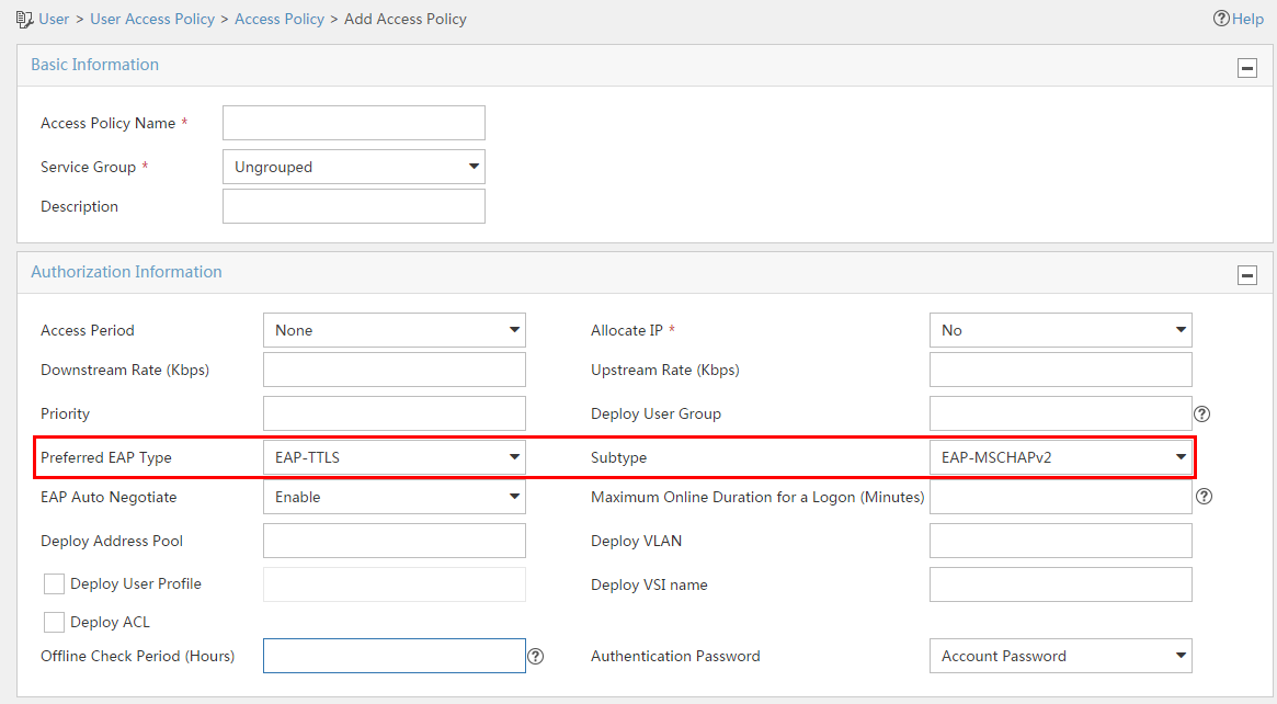
Configuring the iNode client
1. Import the root certificate and client certificate to the PC installed with the iNode client.
2. When creating the 802.1X authentication connection on the iNode client, enable certificate authentication and select the right client certificate.
3. On the account information page, select the Enable advanced authentication box and then select the Certificate authN option, as shown in Figure 68.
Figure 68 Selecting certificate authentication

4. Click Certificate to display the certificate configuration page.
5. Select an authentication type, which must be the same as the certificate type selected for the access device in UAM, as shown in Figure 69.
Figure 69 Configuring the certificate
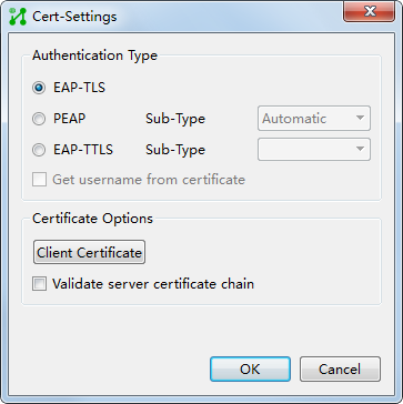
6. Click Select certificate to select the client certificate for authentication, as shown in Figure 70.
Figure 70 Selecting the client certificate

Portal authentication and certificate authentication
To use certificate authentication, you must adjust the configuration for portal authentication and UAM local authentication.
Importing the root certificate and server certificate to UAM
To display the page for importing certificates to UAM, click the User tab and select User Access Policy > Service Parameters > Certificate from the navigation tree, as shown in Figure 71.
For more configuration information, see "Configuring certificate authentication."
Figure 71 Displaying the certificate configuration page

Configuring a preferred EAP type when adding an access policy
1. To display the access policy configuration page, click the User tab and select User Access Policy > Access policy from the navigation tree.
2. Click Add to add an access policy. As shown in Figure 72, select a preferred EAP authentication type and a subtype for the access policy.
For other configuration for the access policy, see "Configuring access policies."
Figure 72 Adding an access policy

Configuring the access device
No specific configuration is required on the access device. However, the access device must support portal EAP authentication. To see whether your access device supports the portal EAP authentication feature, check the device's portal configuration guide.
Configuring the iNode client
1. Import the root certificate and client certificate to the PC installed with the iNode client.
2. When creating the portal authentication connection on the iNode client, enable certificate authentication and select the right client certificate.
3. On the portal connection basic attributes page, select the Enable advanced authentication option, and then select Certificate Authentication, as shown in Figure 73.
Figure 73 Selecting certificate authentication

4. Click Cert-Settings to display the certificate configuration page. Select an authentication type, which must be the same as the certificate type selected for the access device in UAM, as shown in Figure 74.
Figure 74 Configuring the certificate

5. Click Client Certificate to select the client certificate for authentication.
Roaming authentication
In roaming authentication, a foreign UAM (UAM 1 in the figure) receives user authentication requests. It has no user information, and it needs to forward the requests to a home UAM (UAM 2 in the figure) that has saved the user information for identity authentication.
The combinations of roaming authentication and an access control method include:
· 802.1X authentication and roaming authentication
· Portal authentication and roaming authentication
· VPN authentication and roaming authentication
· MAC authentication and roaming authentication
For these authentication combinations, the access device configuration and the iNode client configuration are the same as those described in "802.1X authentication and UAM local authentication," "Portal authentication and UAM local authentication," "Anonymous MAC authentication," "Transparent MAC authentication," or "VPN authentication and UAM local authentication." See Figure 75 for an example that shows the configuration on UAM systems for roaming authentication.
Figure 75 Recommended configuration procedure
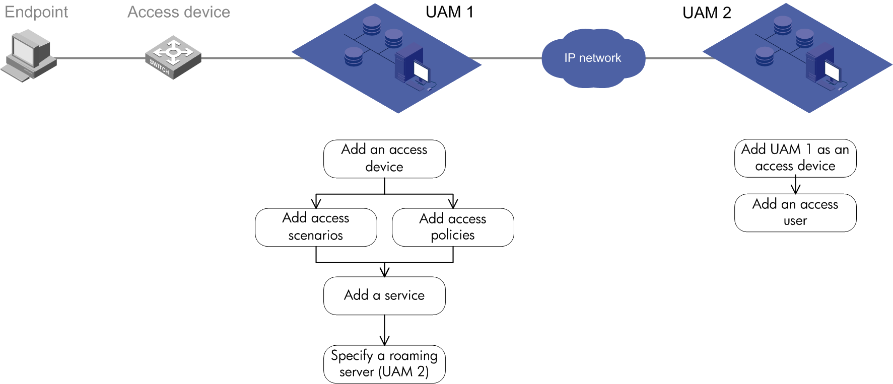
UAM 1 configuration
To configure RADIUS authentication on UAM 1:
1. Configure the access device.
2. Configure the access condition.
3. Configure the access policy.
4. Configure a service.
5. Specify a roaming server (UAM 2).
Configuring the access device
Access device configuration is a prerequisite for configuring the access location group of an access condition. As a best practice, configure the access device first.
You must add the access device's information (such as the vendor name, IP address, port number, and key) to UAM, so UAM can exchange RADIUS packets with the access device during authentication.
To display the access device configuration page, click the User tab and select User Access Policy > Access Device Management > Access Device from the navigation tree, as shown in Figure 76.
For more configuration information, see "Configuring access devices."
Figure 76 Displaying the access device configuration page

Configuring the access condition
An access condition is the endpoint user's environment when the user accesses the network, including time, location, endpoint, network type, and other elements. UAM differentiates users based on the access conditions.
You need to configure a combination of the access condition and the access policy for a service. Therefore, you must configure the access condition.
To display the access condition configuration page, click the User tab and select User Access Policy > Access Condition from the navigation tree, as shown in Figure 77. The Access Condition area provides links to the configuration pages of the following:
· Access period policy
· Access location group
· SSID group
· Endpoint IP group
· Endpoint MAC group
· Endpoint vendor group
· Endpoint type group
· Endpoint OS group
For more configuration information, see "Configuring access conditions."
Figure 77 Displaying the access condition configuration page

Configuring an access policy
An access policy refers to a set of control rules applied to endpoint users. UAM supports applying different access policies to users from different scenarios.
You need to configure the combination of the access policy and the access condition for a service. Therefore, you must configure the access policy.
An access policy includes:
· Access policy
· Security check
· Proprietary attribute assignment policy
· Internet access control
Security check and Internet access control are available after you deploy the EAD component. For more information about security check and Internet access control, see HPE Intelligent Management Center v7.3 EAD Security Policy Administrator Guide.
To display the access policy configuration page, click the User tab and select User Access Policy > Access Policy from the navigation tree, as shown in Figure 78.
For more configuration information, see "Configuring access policies."
Figure 78 Displaying the access policy configuration page

To display the proprietary attribute configuration page, click the User tab and select User Access Policy > Access Device Management > Proprietary Attribute from the navigation tree, as shown in Figure 79.
For more configuration information, see "Configuring proprietary attribute assignment policies."
Figure 79 Displaying the proprietary attribute configuration page

Configuring a service
A service is a set of access policies applied in specific access conditions. You must add services before adding access users. When you add an access user, apply for a service for the user.
To display the service configuration page, click the User tab and select User Access Policy > Access Service from the navigation tree, as shown in Figure 80. For more configuration information, see "Configuring access services."
Figure 80 Displaying the access service page

Specifying a foreign server (UAM 2)
Specify a foreign server (UAM 2 in this example) on IMC UAM 1. When UAM 1 receives an authentication request from a user, it examines whether the user's service needs roaming authentication. If yes, UAM 1 forwards the request to UAM 2. UAM 2 determines whether the user can pass the authentication.
1. To display the roaming server configuration page, click the User tab and select User Access Policy > Service Parameters > System Settings from the navigation tree.
2. Click the Configure icon ![]() for the Roaming Configuration item to display the roaming server configuration
page, as shown in Figure 81.
for the Roaming Configuration item to display the roaming server configuration
page, as shown in Figure 81.
For more configuration information, see "Configuring roaming authentication."
Figure 81 System configuration page
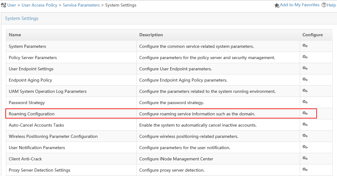
UAM 2 configuration
To configure UAM 2:
1. Configure UAM 1 as an access device.
2. Configure access users.
Configuring UAM 1 as an access device
During authentication, UAM 2 only receives RADIUS packets sent from UAM 1 and verifies the user name and password forwarded from UAM 1.
When you configure UAM 1 as an access device, follow these guidelines:
· The shared key and authentication/accounting port specified in the RADIUS scheme must be consistent with those configured for the access device on UAM 1.
· Select LAN access as the service type.
· Select HP (Comware) or H3C (General) as the access device type.
· Configure the gateway IP address of UAM 2 as the IP address of the access device.
To display the access device configuration page, click the User tab and select User Access Policy > Access Device Management > Access Device from the navigation tree, as shown in Figure 82.
For information about configuring access devices, see "Configuring access devices."
Figure 82 Displaying the access device configuration page

Configuring access users
To display the access user configuration page, click the User tab and select Access User > All Access Users from the navigation tree, as shown in Figure 83.
For more configuration information, see "Managing ordinary access users."
Figure 83 Displaying the access user configuration page
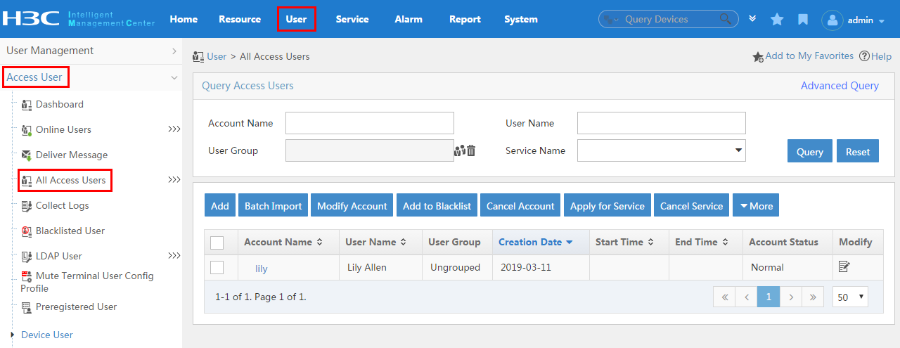
UAM menus and common operations
Navigation menu
1. Click the User tab on the top navigation bar. The UAM navigation menu includes the following items:
· Access User (see Table 9).
· Guest (see Table 10).
· User Endpoint (see Table 11).
· User Access Log (see Table 12).
· User Access Policy (see Table 13).
|
Item |
Function |
|
Online Users |
Allows you to view online users and endpoint information. You can also send them messages or log them off. |
|
Deliver Message |
Allows you to query, add, modify, or delete the messages to be delivered. |
|
All Access Users |
Allows you to query, add, modify, or delete access users. You can also assign, apply for, or cancel services for access users, and make batch operations to access users. |
|
Blacklisted User |
Allows you to view or release the blacklisted users. |
|
LDAP User |
Allows you to bind access users with or unbind access users from an LDAP synchronization policy. You can also synchronize LDAP users. |
|
Mute Terminal User Configuration Profile |
Allows you to query, add, modify, or delete configuration profiles for mute terminal users. |
|
Preregistered User |
Allows you to process preregistration requests from endpoint users. |
|
Device User |
Provides access to the following device user configuration pages: · Device User—Allows you to query, add, modify, or delete device users. · Device User Group—Allows you to query, add, modify, or delete device user groups. |
|
Access Topology |
Allows you to query, add, modify, or delete access views. You can also view or manage the topology of an access view. |
|
Batch Operations |
Allows you to import, maintain, and export access users in batches. You can also export access details in batches. |
|
Trouble Report |
Provides access to the following trouble report pages: · FAQ—Allows you to query, add, modify, or delete FAQs. Endpoint users can view the FAQs in the self-service center. · Trouble Ticket—Allows you to process trouble tickets that are submitted by endpoint users. · Custom TSHOOT Field—Allows you to customize fields for a trouble ticket. Endpoint users need to fill in these fields when they submit a trouble report. |
|
Quick Experience |
Allows you to configure authentication and service parameters so that endpoint users can have a quick experience of the authentication process. |
|
Item |
Function |
|
All Guests |
Allows you to query, delete, or blacklist guests. |
|
Guest Manager |
Allows you to query, add, modify, or delete guest managers. |
|
Guest Service |
Allows you to add or delete services that can be assigned to guests. |
|
Guest Policy |
Allows you to query, add, modify, or delete guest policies. |
|
Guest Parameters |
Allows you to configure the global parameters for guest management. |
|
Guest Information Printing Configuration |
Allows you to configure the format and content of the guest information to be printed. |
|
Item |
Function |
|
Endpoint Management |
Allows you to view and manage the correlations between the endpoint device information and the account name. You can also configure transparent MAC authentication for endpoint devices. |
|
Endpoint Configuration Distribution Policy |
Allows you to query, add, modify, or delete configuration distribution policies for endpoints. |
|
Endpoint Configuration Templates |
Allows you to query, add, modify, or delete endpoint configuration templates. |
|
Endpoint Configuration History |
Allows you to view the history of deployment from configuration templates to endpoints. |
|
Endpoint Profiling |
Allows you to query, add, modify, or delete the correlations between endpoint information and characters (such as DHCP, HTTP User Agent, and MAC). |
|
Device Fingerprint |
Allows you to query, add, modify, or delete the endpoint information, such as vendor, type, and operating system. |
|
Item |
Function |
|
Authentication Failure Log |
Allows you to view the authentication failure logs and analyze authentication failure reasons. |
|
Access Details |
Allows you to view login details about endpoint users, including the account name, service name, user IP address, access duration, and the endpoint information. |
|
Roaming Access Details |
Allows you to view login details about roaming users, including the login name, device IP address, and access duration. |
|
Authentication Violation Log |
Allows you to view authentication violation information for endpoint users, including the account name, user IP address, user MAC address, violation duration, and violation type. |
|
Self-Service Log |
Allows you to view the operation logs that are generated for endpoint users at the self-service center. |
|
Device User AuthN Log |
Allows you to view the authentication information for device users, including the account name, service type, authentication time, and authentication result. |
|
Endpoint Conflict Audit |
Allows you to view conflicts for the endpoint information compared to the stored information in UAM during endpoint user authentication. |
Table 13 User Access Policy menu
|
Item |
Function |
|
Quick Start |
Provides you with the configuration process to implement authentication by UAM. |
|
Access Service |
Allows you to query, add, modify, or delete access services. |
|
Access Policy |
Allows you to query, add, modify, or delete an access policy and its sub-items, which includes SSID Access Control, Hard Disk Serial Number, Access MAC Address, Access ACL, and Access Period Policy. |
|
Access Condition |
Provides access to the following access conditions pages: · Access Period Policy—Allows you to query, add, modify, or delete access period policies. Different access conditions apply if the time periods for network access match two or more access period policies. · Access Location Group—Allows you to query, add, modify, or delete access location groups. Different access conditions apply if the access devices to which the endpoint users connect are located in two or more access location groups. · SSID Group—Allows you to query, add, modify, or delete SSID groups. Different access conditions apply if the SSIDs to which the wireless users connect are located in two or more SSID groups. · Endpoint IP Group—Allows you to query, add, modify, or delete endpoint IP groups. Different access conditions apply if the endpoints' IP addresses are located in two or more endpoint IP groups. · Endpoint MAC Group—Allows you to query, add, modify, or delete endpoint MAC groups. Different access conditions apply if the endpoints' MAC addresses are located in two or more endpoint MAC groups. · Endpoint Vendor Group—Allows you to query, add, modify, or delete endpoint vendor groups. Different access conditions apply if the endpoint vendors are located in two or more endpoint vendor groups. · Endpoint Type Group—Allows you to query, add, modify, or delete endpoint type groups. Different access conditions apply if the endpoint types are located in two or more endpoint type groups. · Endpoint OS Group—Allows you to query, add, modify, or delete endpoint OS groups. Different access conditions apply if the endpoint operating systems are located in two or more endpoint OS groups. · AP Group—Allows you to query, add, modify, or delete AP groups. Different access conditions apply if APs that the endpoints are located in two or more AP groups. |
|
Access Device Management |
Provides access to the following access device management pages: · Access Device—Allows you to query, add, modify, or delete access devices. You can also deploy configurations to access devices. · Access Device Type—Allows you to query, add, modify, or delete access device types. · Proprietary Attribute—Allows you to query, add, modify, or delete proprietary attributes. A proprietary attribute assignment policy deploys specific attributes to non-HP devices. |
|
LDAP Service |
Provides access to the following LDAP service pages: · LDAP Server—Allows you to query, add, modify, or delete LDAP servers. You can also configure certificates and modify the admin password. · Sync Policy—Allows you to query, add, modify, delete, or execute LDAP policies for user synchronization. · User Export—Allows you to export users from an LDAP server and save them to a file. · LDAP Parameters—Allows you to configure LDAP service parameters. |
|
Portal Service |
Provides access to the following portal service pages: · Server—Allows you to configure parameters for the portal server. · Device—Allows you to query, add, modify, or delete portal devices and port groups on the portal devices. · IP Group—Allows you to query, add, modify, or delete IP groups. |
|
Service Parameters |
Provides access to the following service parameters pages: · System Settings—Allows you to configure global parameters or functions for UAM. · Certificate—Allows you to import root certificates and server certificates to UAM. · Client Upgrade—Allows you to query, add, modify, or delete tasks to upgrade the version or configuration of iNode PC clients. · Smart Client Upgrade—Allows you to manage versions of iNode mobile clients for automatic upgrade. · Unified Authentication—Allows you to configure unified authentication for various applications, including Web Application System > Portal, Web Application System > Self-Service, and iNode Client Shortcut Configuration. · Validate—Allows you to manually validate the service parameter settings. |
|
Third-Party Authentication |
Allows you to configure third-party authentication through a database, Web service, or custom plug-in. |
|
Export Tasks |
Allows you to schedule tasks to periodically export LAN access details and account information. |
|
Customize Terminal Pages |
Provides access to the following customizable terminal pages and the page push policy configuration page: · Portal Page—Allows you to customize portal pages for PCs and smart devices. You can also import external portal pages to UAM for management. · Preregistration Page—Allows you to customize preregistration pages for PCs and smart devices. · BYOD Page—Allows you to customize BYOD pages for PCs and smart devices. You can also import external BYOD pages to UAM for management. · Self-Service Page—Allows you to modify the login page of the self-service center and customize menus displayed in the PC version of the Self-Service Center. · Page Push Policy—Allows you to add, modify, and delete page push policies. |
Common operations
Sorting a list
You can sort a list by every field that
contains a Sort icon ![]() in the column
label.
in the column
label.
· When the list is sorted by a field in ascending
order, the column label of the selected field is blue and contains an Ascending icon ![]() .
.
· When the list is sorted by a field in descending
order, the column label of the selected field is blue and contains a Descending icon ![]() .
.
Navigating a list
If a list contains enough entries, use the following aids to navigate the list:
· Click the Next Page
icon ![]() to page
forward in the list.
to page
forward in the list.
· Click the Last Page
icon ![]() to page
forward to the end of the list.
to page
forward to the end of the list.
· Click the Previous Page
icon ![]() to page
backward in the list.
to page
backward in the list.
· Click the First Page
icon ![]() to page
backward to the front of the list.
to page
backward to the front of the list.
· Click a page number to display the page in the list.
· Select 8, 15, 50, 100, 200, or 1000 at the bottom of the list to configure how many items per page you want to display.
Importing devices
You can import devices from the IMC platform to UAM.
Accessing the window for selecting devices
In the Device List area of the Add Access Device page, click Select to open the window for selecting devices by view or by advanced query.
Filtering devices by view
1. In the Query Conditions area, click the By View tab.
2. Click the Expand
icon ![]() to the left of the IP View, Device View, or Custom View field, and then select a subview.
to the left of the IP View, Device View, or Custom View field, and then select a subview.
The views are described as follows:
¡ IP View—Displays devices by network segment.
¡ Device View—Displays devices by device category.
¡ Custom View—Displays devices by custom view. The view has a subview named Devices Not In Views to display devices that do not belong to any custom view.
All devices in the subview are displayed in the Devices Found area.
Filtering devices by advanced query
1. In the Query Conditions area, click the Advanced tab.
2. Specify one or more of the following query criteria:
¡ Device IP—Enter an IPv4 address for devices.
If Exact Query is selected, enter a complete IPv4 address. If Exact Query is not selected, enter a partial or complete IPv4 address.
¡ Device IP List—Click the Configuration icon ![]() next to the Device IP List field to perform an exact query for multiple devices.
next to the Device IP List field to perform an exact query for multiple devices.
In the Device IP List Configuration window, enter multiple IP addresses separated by commas, semicolons, or carriage returns, click Add, and click OK.
¡ Device Label—Enter a partial or complete device label.
¡ Device Status—Select a device state from the list: Unmanaged, Unknown, Normal, Warning, Minor, Major, or Critical.
¡ Device Category—Select a device type from the list: Routers, Switches, Servers, Security, Storage, Wireless, Voice, Surveillance, Video, Virtual Devices, Module, Application Controller, Printers, UPS, Desktops, or Others.
¡ Device Series—Select a device series from the list. Options include all device series that are added to the IMC platform.
¡ Contact—Enter partial or complete contact information for devices. This criterion is case-insensitive.
¡ Location—Enter partial or complete location information for devices. This criterion is case-insensitive.
¡ Device Reachability—Select a reachability state from the list: Reachable or Unreachable.
The query ignores empty fields.
3. Click Query.
All matching devices are displayed in the Devices Found area.
Selecting devices
1. Add devices to the Selected Devices area:
¡ To
add one or more devices, select the devices in the Devices Found area and
click the Add icon ![]() .
.
¡ To
add all devices, click the Add all icon ![]() .
.
2. Remove undesired devices from the Selected Devices area:
¡ To remove one or more devices, select the
devices in the Selected Devices area and click
the Remove icon ![]() .
.
¡ To
remove all devices, click the Remove all icon ![]() .
.
|
|
NOTE: · If fewer than two devices are found, the
window does not include the Add all icon · To select multiple devices, press Ctrl when you select the devices. |
3. Click OK.
4. In the Import Devices page, click OK.
The page displays the import progress and results:
¡ Import progress—Displays the number of waiting devices and the number of imported devices.
¡ Time—Displays the import progress at a specific time in the format YYYY-MM-DD hh:mm:ss.
¡ Result—Displays the import results.
Service quick experience
UAM provides a Quick Experience page, which presents all necessary parameters to complete authentication, including service, user account, and access device parameters. Operators can promptly complete configuration on this page and verify the user authentication result in UAM.
To support service quick experience, make sure your access device is an HP Comware, general HP, or general H3C device.
Configuring service quick experience
1. Click the User tab.
2. From the navigation tree, select Access User > Quick Experience.
The Quick Experience page opens.
3. In the User Configuration area, enter the account name and password.
IMC will automatically create an ungrouped user account, which has the same name and identity number as this account name.
4. In the Access Service area, configure the following service parameters:
¡ Service Name—Enter the service name or use the default setting. The default service name is in the format of srv-date and time, where the date and time string indicates the time when you accessed the Quick Experience page.
¡ Service Suffix—Enter the service suffix. UAM will automatically create a domain named the same as the service suffix on the access device for authentication. If the domain already exists on the access device, the access device configuration in the service quick experience settings will overwrite the domain setting.
UAM converts the service settings into commands and delivers them to the access device.
5. In the Access Service area, select Enable Security Policy to configure a security policy.
This parameter is displayed only when EAD is deployed. When the Enable Security Policy option is selected, the Quick Experience page refreshes to display the following parameters:
¡ Security Policy Name—Enter the security policy name or use the default setting. The default security policy name is in the format of policy-date and time, where the date and time string indicates the time when you accessed the Quick Experience page.
¡ Security Level—Select a security level. Options and their default settings are as follows:
- Monitor Mode—Monitors the access user who fails any security check item defined in the security policy, allows the user to access the network without informing the user of any security vulnerability on the user endpoint, and generates a security log.
- VIP Mode—Informs the access user who fails any security check item defined in the security policy, allows the user to access the network, informs the user of the security vulnerability on the user endpoint and remediation methods, and generates a security log.
- Isolate Mode—Isolates the access user who fails any security check item defined in the security policy in a restricted area, informs the user of the security vulnerability and remediation methods, and generates a security log.
- Kick Out Mode—Disconnects the access user who fails any security check item defined in the security policy, informs the user of the security vulnerability on the user endpoint, and generates a security log.
- Guest Mode—Disconnects the access user 5 minutes after the user fails any security check item defined in the security policy, informs the user of the security vulnerability on the user endpoint, and generates a security log.
If an operator has modified the settings, the user-defined settings apply.
¡ Check Anti-Virus Software—Select this option if you want EAD to check the anti-virus software on the user endpoint.
¡ Check Required Processes—Select this option if you want EAD to check a process on the user endpoint, and then enter the process name. Make sure the process name is the same as that in the Windows Task Manager. This parameter takes effect on only Windows endpoints.
6. Select Access Device Configuration.
The Access Device Configuration area is displayed.
7. In the Access Device Configuration area, click Add Devices if your access device is not added to the IMC platform. The page for adding devices to IMC opens. For more information, see HPE Intelligent Management Center v7.3 Enterprise and Standard Platform Administrator Guide.
8. Select the authentication method to use: 802.1X Authentication or Portal Authentication. The page refreshes to display the authentication parameters according to the authentication method you select.
9. If you selected 802.1X Authentication, configure the following parameters:
¡ Access Device—Click Select Device and AuthN Port, and in the window that opens, select one or more ports for which you want to enable 802.1X authentication.
To ensure successful configuration, make sure the selected ports are the bridge link type and located on HP Comware, general HP, or general H3C devices.
¡ Authentication Port—The Authentication Port area is automatically populated with the description and alias of the ports you selected for 802.1X authentication.
10. If you selected Portal Authentication, configure the following parameters:
¡ Access Device—Click Select Device and AuthN Port, and in the window that opens, select one port for which you want to enable portal authentication.
To ensure successful configuration, make sure the selected port is not a null or loopback port, has an IP address configured, and is located on an HP Comware, general HP, or general H3C device.
¡ Network Mode—Select the network mode used by the access device. Select Layer 3 if Layer 3 devices exist between the endpoint user and the access device. Otherwise, select Directly Connected.
¡ Source Authentication Network—Enter the range of the IP addresses for which portal authentication is permitted.
The access device uses this parameter to determine whether portal authentication is permitted for the user. This parameter is required when Layer 3 is selected as the network mode. Otherwise, it is optional.
¡ Start/End IP in IP Address Group—Enter the start and end IP addresses of the IP address group for which portal authentication is permitted.
UAM uses the IP address group to determine whether portal authentication is permitted for the user. The IP address group cannot exceed the range of the source authentication network.
In addition, UAM can apply different policies to users specific to the IP address groups to which they belong. For more information, see "Configuring IP address groups."
¡ Authentication Port—The Authentication Port area is automatically populated with the description, alias, and IP address of the port you selected for portal authentication.
11. Click OK.
IMC applies the service quick experience settings and displays the configuration result. Modify the settings if you see any error message. When all parameters are properly configured, UAM is ready for user authentication and you can view the account, service, security policy, access device, portal device, and IP address group settings in UAM and EAD.
Creating a service quick experience
1. Connect a PC to one of the authentication ports.
2. Manually assign an IP address to the PC or setup a DHCP server for dynamic address allocation.
If you want to use portal authentication, make sure the IP address allocated by the DHCP server is located within the address range of the specified IP address group.
3. Install the iNode client on the PC.
4. Create an 802.1X or portal authentication connection in the iNode client.
5. Trigger an authentication process by using the connection. Make sure the account name for authentication is the same as that configured in the service quick settings. If a service suffix is configured in the service quick settings, use account name@service suffix for authentication.
6. View the authentication process and result in the message area of the iNode client.
Accessing service configuration wizard
To access the service configuration wizard page:
1. On the IMC homepage, click the User tab.
2. From the navigation tree, select User Access Policy > Quick Start.
3. Click the Service Configuration Wizard tab.
The service configuration wizard includes the following areas:
· Interested Devices—Displays faulty access devices. The access devices must have been added to the IMC platform to work with the alarm function. The device icons vary in color by the severity level of alarms generated on the access devices. Click a device icon to view detailed information about the access device. For information about viewing the access device details, see HPE Intelligent Management Center v7.3 Enterprise and Standard Platform Administrator Guide.
· Authentication Configuration Wizard—Demonstrates the configuration process for 802.1 X authentication. Click an icon or link on the flowchart to display the corresponding configuration page.
· Portal Authentication Configuration Wizard—Demonstrates the configuration process for portal authentication. Click an icon or link on the flowchart to display the corresponding configuration page.
· AD PEAP Authentication Configuration Wizard—Demonstrates the configuration process for AD PEAP authentication. Click an icon or link on the flowchart to display the corresponding configuration page.
Using the service fast deploy function
On the Service Fast Deploy page, an operator can quickly configure and deploy services to endpoint users of the following types:
· Guests using MAC authentication
· Employees using MAC authentication
· Employees using 802.1X authentication
Configuring service fast deploy for guest MAC authentication
UAM performs guest MAC authentication in the following scenarios:
· Anonymous users access the network. They must first register as guests, and then access the network using the guest accounts.
· Registered guests access the network.
Guest MAC authentication uses the workflow shown in Figure 84.
Figure 84 Guest MAC authentication workflow
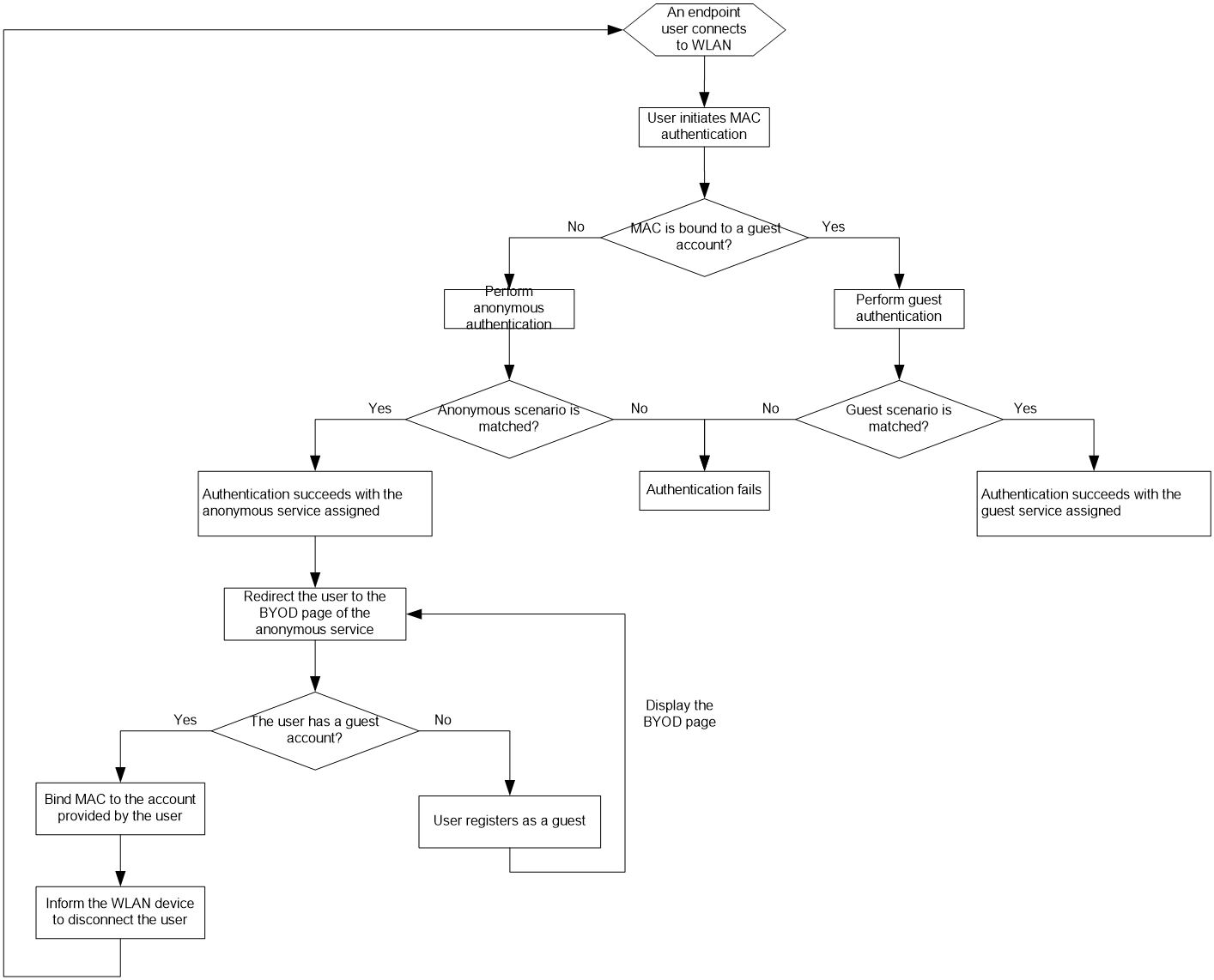
To configure service fast deploy for guest MAC authentication:
1. Click the User tab.
2. From the navigation tree, select User Access Policy > Quick Start.
3. Click the Service Fast Deploy tab.
4. Select Guest MAC from the Template list.
5. Configure a guest manager:
a. Click Select next to the Account Name field.
b. Select an existing access user as the guest manager. UAM automatically sets the user as the default guest manager.
6. Configure an SSID group using one of the following methods:
¡ Select an existing group from the SSID Group list.
¡ Click Add next to the SSID Group list to configure a new group.
The group must include the SSID to be connected by endpoint users. Make sure the SSID is associated with MAC authentication on the WLAN device, such as an AC.
7. Configure parameters of the anonymous service for unregistered guests:
¡ Service Name—UAM automatically generates a name for the anonymous service.
¡ Access Policy Name—Enter the name of an access policy.
¡ Deploy VLAN—Enter a VLAN ID or name. UAM deploys the VLAN to users who match the anonymous scenario.
¡ BYOD Page—Select a login page from the list. UAM pushes the page to users who match the anonymous scenario. For information about customizing a BYOD page, see "Managing and applying BYOD page sets."
¡ Endpoint Vendor/Type/OS Group—Select a group from the list, or click Add to configure a new group. These groups filter users for the anonymous scenario based on endpoints. Select Unlimited to disable a filter.
8. Configure parameters of the guest service for registered guests:
¡ Service Name—UAM automatically generates a name for the guest service.
¡ Access Policy Name—Enter the name of an access policy.
¡ Deploy VLAN—Enter a VLAN ID or name. UAM deploys the VLAN to users who match the guest scenario.
¡ BYOD Page—Select a login page from the list. UAM pushes the page to users who match the guest scenario. For information about customizing a BYOD page, see "Managing and applying BYOD page sets."
¡ Endpoint Vendor/Type/OS Group—Select a group from the list, or click Add to configure a new group. These groups filter users for the guest scenario based on endpoints. Select Unlimited to disable a filter.
9. Add NAS devices to UAM as access devices:
a. Select Add Access Device.
b. Configure an IP address range of NAS devices in the Start IP and End IP fields. The IP address range must include the IP address specified by using the nas-ip command for the RADIUS scheme on the NAS devices. If the NAS IP address is not specified, the IP address range must include the IP address of the interface connecting to UAM. The connecting interface can be an Ethernet interface or VLAN interface.
c. Enter a shared key in the Shared Key and Confirm Shared Key fields to secure RADIUS authentication and accounting communication. The shared key must be the same as that configured on the NAS devices.
d. Select a type from the Access Device Type list.
10. Click OK.
11. To restore default settings of all parameters, click Reset.
Configuring service fast deploy for employee MAC authentication
UAM performs employee MAC authentication in the following scenarios:
· Employees access the network from endpoint devices with transparent authentication enabled.
· Employees access the network from endpoint devices with transparent authentication disabled. UAM first enables transparent authentication on the endpoint devices, and then allows the employees to access the network.
Employee MAC authentication uses the workflow, as shown in Figure 85.
Figure 85 Employee MAC authentication workflow
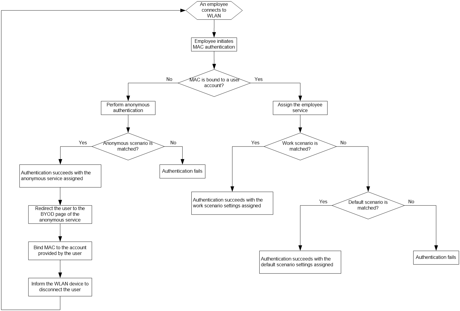
To configure service fast deploy for employee MAC authentication:
1. Click the User tab.
2. From the navigation tree, select User Access Policy > Quick Start.
3. Click the Service Fast Deploy tab.
4. Select Employee MAC from the Template list.
5. Configure an SSID group using one of the following methods:
¡ Select an existing group from the SSID Group list.
¡ Click Add next to the SSID Group list to add a new group.
The group must include the SSID to be connected by endpoint users. Make sure the SSID is associated with MAC authentication on the WLAN device, such as an AC.
6. Configure parameters of the anonymous service, which applies to users on endpoints with transparent authentication disabled:
¡ Service Name—UAM automatically generates a name for the anonymous service.
¡ Access Policy Name—Enter the name of an access policy.
¡ Deploy VLAN—Enter a VLAN ID or name. UAM will deploy the VLAN to users who match the anonymous scenario.
¡ BYOD Page—Select a login page from the list. UAM will push the page to users who match the anonymous scenario. For information about customizing a BYOD page, see "Managing and applying BYOD page sets."
¡ Endpoint Vendor/Type/OS Group—Select a group from the list, or click Add to configure a new group. These groups filter users for the anonymous scenario based on endpoints. Select Unlimited to disable a filter.
7. Configure the service name for the employee service. UAM automatically generates a name for the employee service.
8. Configure default scenario parameters for the employee service, which applies to users on endpoints with transparent authentication enabled:
¡ Access Policy Name—Enter the name of an access policy.
¡ Deploy VLAN—Enter a VLAN ID or name. UAM will deploy the VLAN to users who match the default scenario.
¡ BYOD Page—Select a login page from the list. UAM will push the page to users who match the default scenario. For information about customizing a BYOD page, see "Managing and applying BYOD page sets."
9. Configure work scenario parameters for the employee service, which applies to users on endpoints with transparent authentication enabled:
¡ Access Policy Name—Enter the name of an access policy.
¡ Deploy VLAN—Enter a VLAN ID or name. UAM deploys the VLAN to users who match the work scenario.
¡ BYOD Page—Select a login page from the list. UAM pushes the page to users who match the work scenario. For information about customizing a BYOD page, see "Managing and applying BYOD page sets."
¡ Endpoint Vendor/Type/OS Group—Select a group from the list, or click Add to configure a new group. These groups filter users for the work scenario based on endpoints. Select Unlimited to disable a filter.
10. Add NAS devices to UAM as access devices:
a. Select Add Access Device.
b. Configure an IP address range of NAS devices in the Start IP and End IP fields. The IP address range must include the IP address specified using the nas-ip command for the RADIUS scheme on the NAS devices. If the NAS IP address is not specified, the IP address range must include the IP address of the interface connecting to UAM. The connecting interface can be an Ethernet interface or VLAN interface.
c. Enter a shared key in the Shared Key and Confirm Shared Key fields to secure RADIUS authentication and accounting communication. The shared key must be the same as that configured on the NAS devices.
d. Select a type from the Access Device Type list.
11. Click OK.
12. To restore default settings of all parameters, click Reset.
Configuring service fast deploy for employee 802.1X authentication
Configure service fast deploy for employees who pass 802.1X authentication to access the enterprise network.
Employee 802.1X authentication uses the workflow, as shown in Figure 86.
Figure 86 Employee 802.1X authentication workflow
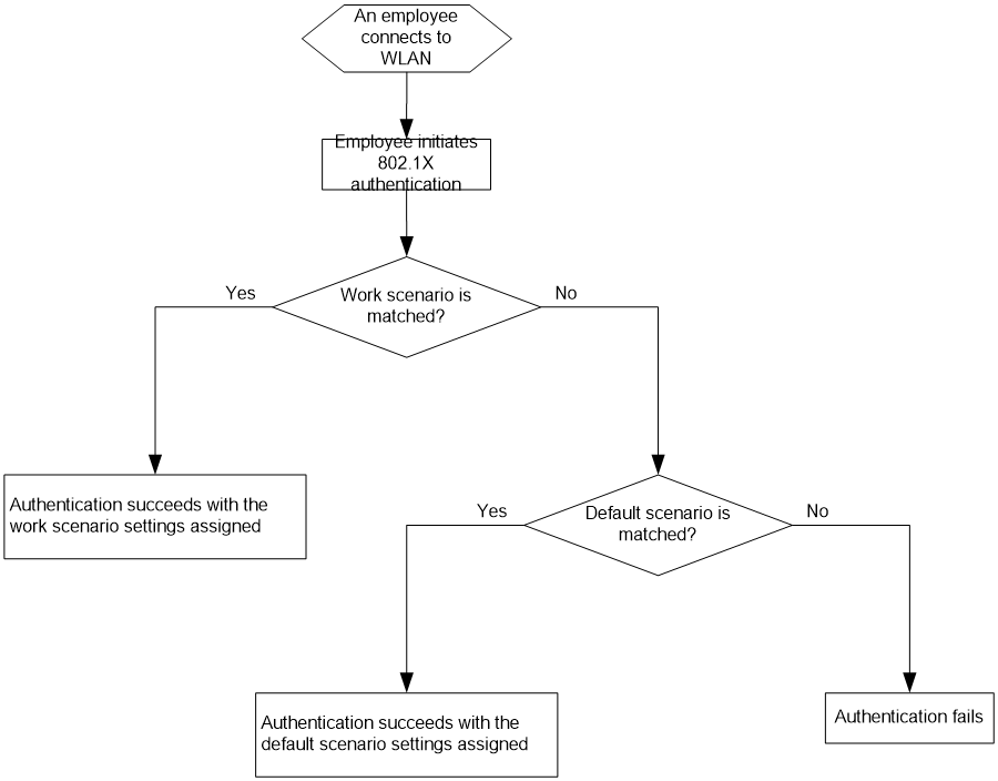
To configure service fast deploy for employee 802.1X authentication:
1. Click the User tab.
2. From the navigation tree, select User Access Policy > Quick Start.
3. Click the Service Fast Deploy tab.
4. Select Employee 802.1X from the Template list.
5. Configure an SSID group using one of the following methods:
¡ Select an existing group from the SSID Group list.
¡ Click Add next to the SSID Group list to add a new group.
The group must include the SSID to be connected by endpoint users. Make sure the SSID is associated with 802.1X authentication on the WLAN device, such as an AC.
6. Configure the service name for the employee service.
UAM automatically generates a name for the employee service.
7. Configure default scenario parameters for the access service:
¡ Access Policy Name—Enter the name of an access policy.
¡ Deploy VLAN—Enter a VLAN ID or name. UAM will deploy the VLAN to users who match the default scenario.
¡ BYOD Page—Select a login page from the list. UAM will push the page to users who match the default scenario. For information about customizing a BYOD page, see "Managing and applying BYOD page sets."
8. Configure work scenario parameters for the access service:
¡ Access Policy Name—Enter the name of an access policy.
¡ Deploy VLAN—Enter a VLAN ID or name. UAM will deploy the VLAN to users who match the work scenario.
¡ BYOD Page—Select a login page from the list. UAM will push the page to users who match the work scenario. For information about customizing a BYOD page, see "Managing and applying BYOD page sets."
¡ Endpoint Vendor/Type/OS Group—Select a group from the list, or click Add to configure a new group. These groups filter users for the work scenario based on endpoints. Select Unlimited to disable a filter.
9. Add NAS devices to UAM as access devices:
a. Select Add Access Device.
Configure an IP address range of NAS devices in the Start IP and End IP fields. The IP address range must include the IP address specified using the nas-ip command for the RADIUS scheme on the NAS devices. If the NAS IP address is not specified, the IP address range must include the IP address of the interface connecting to UAM. The connecting interface can be an Ethernet interface or VLAN interface.
b. Enter a shared key in the Shared Key and Confirm Shared Key fields to secure RADIUS authentication and accounting communication. The shared key must be the same as that configured on the NAS devices.
c. Select a type from the Access Device Type list.
10. Click OK.
11. To restore default settings of all parameters, click Reset.
Configuring access conditions
BYOD also uses the following concepts:
· Access policy—Defines a set of control methods for endpoint users. For more information, see "Configuring access policies."
· Access scenario—Defines the access policy to take effect on a specific access condition.
To implement BYOD:
1. In UAM, the operator defines access conditions and access policies.
2. In UAM, the operator defines one or more access scenarios for a specific service, and maps access conditions to access policies in each access scenario.
3. When an endpoint user attempts to access the network by using the service, UAM identifies the access conditions for the endpoint user and applies the correct access policy to the endpoint user.
UAM identifies endpoint users based on a set of access conditions, as described in Table 14.
|
Access condition |
Description |
|
Access period policy |
Different access conditions apply if the time periods at which the endpoint users access the network match two or more access period policies. For more information, see "Configuring access period policies." |
|
Access location group |
Different access conditions apply if the access devices to which the endpoint users connect are located in two or more access location groups. For more information, see "Configuring access location groups." |
|
SSID group |
Different access conditions apply if the SSIDs to which the wireless users connect are located in two or more SSID groups. For more information, see "Configuring SSID groups." |
|
Endpoint IP group |
Different access conditions apply if the endpoints' IP addresses are located in two or more endpoint IP groups. For more information, see "Configuring endpoint IP groups." |
|
Endpoint MAC group |
Different access conditions apply if the endpoints' MAC addresses are located in two or more endpoint MAC groups. For more information, see "Configuring endpoint MAC groups." |
|
Endpoint vendor group |
Different access conditions apply if the endpoint vendors (for example, HP and Apple) are located in two or more endpoint vendor groups. For more information, see "Configuring endpoint vendor groups." |
|
Endpoint type group |
Different access conditions apply if the endpoint types (for example, PC, mobile, and iPhone) are located in two or more endpoint type groups. For more information, see "Configuring endpoint type groups." |
|
Endpoint OS group |
Different access conditions apply if the endpoint operating systems (for example, Windows, iOS, OS X, and Android) are located in two or more endpoint OS groups. For more information, see "Configuring endpoint OS groups." |
|
AP group |
Different access conditions apply if the APs to which the wireless users connect are located in two or more AP groups. For more information, see "Configuring AP groups." |
Configuring access period policies
Access period policies can be used as access conditions in access scenarios or be directly used in access policies. However, an access period policy cannot be used in both an access scenario and an access policy.
When access scenarios include access period policies, UAM can apply different access conditions according to the access time of endpoint users.
Operators can also configure access policies to use access period policies for network access control at different time periods.
Network access is permitted by an access period policy when the following conditions are met:
· The network access time is in the effective time range that is specified by the validity time and expiration time of the policy.
· The network access time is in the permitted time period of the policy.
For example, an access period policy will take effect on 2014-1-1 and expire on 2014-12-31, and the permitted access period is 10:00 to 12:00. With this policy, network access is permitted only from 10:00 to 12:00 in 2014.
Accessing the access period policy list page
1. Click the User tab.
2. From the navigation tree, select User Access Policy > Access Condition > Access Period Policy.
The list includes all access period policies.
Access period policy list contents
¡ Name—Access period policy name, which must be unique in UAM.
¡ Valid from/Expired from—Effective time range of the access period policy.
¡ Service Group—Service group to which the policy belongs.
¡ Apply to—Function module to which the access period policy applies. Access Scenario indicates the access period policy is used by an access scenario as an access condition. Access Policy indicates that the access period policy is used in an access policy.
¡ Default Access Type—Whether or not network access is permitted at time periods that are not specified in the access period policy. The value can be Access Allowed or Access Forbidden.
¡ Modify—Click
the Modify icon ![]() to modify the access period policy.
to modify the access period policy.
¡ Delete—Click
the Delete icon ![]() to delete the access period policy.
to delete the access period policy.
3. Click Refresh on top of the list to view the latest access period policies.
Viewing access period policy details
1. Access the access period policy list page.
2. Click the name of the access period policy you want to view.
The Access Period Policy Details page opens, including the Basic Information and Access Period Information areas.
¡ Basic Information—Includes the following parameters:
- Name—Access period policy name, which must be unique in UAM.
- Valid from/Expired from—Effective time range of the policy.
- Service Group—Service group to which the policy belongs.
- Apply to—Function module to which the access period policy applies. Access Scenario indicates the access period policy is used by an access scenario as an access condition. Access Policy indicates that the access period policy is used in an access policy.
- Default Access Type—Whether or not network access is permitted at time periods that are not specified in the access period policy. The value can be Access Allowed or Access Forbidden.
¡ Access Period Information—Displays a list of access periods in descending order of priority. If a user matches multiple access periods, the access period with the highest priority takes effect.
- Type—The access period types include Once, By Year, By Month, By Week, and By Day. The Once type displays the start time and end time in the format YYYY-MM-DD hh:mm:ss, and takes effect only once. The By Year type displays the start time and end time in the format MM-DD hh:mm:ss, and takes effect within this time range every year. The By Month type displays the start time and end time in the format DD hh:mm:ss, and takes effect within this time range every month. The By Week type displays the start time and end time in the format Day hh:mm:ss, and takes effect within this time range every week. The By Day type displays the start time and end time in the format hh:mm:ss, and takes effect within this time range every day.
- Start Time/End Time—Access period specified by the start and end time.
- Access Type—Whether or not network access is permitted in the access period. The value can be Access Allowed or Access Forbidden.
3. Click Back to return to the access period policy list page.
Adding an access period policy
1. Access the access period policy list page.
2. Click Add to display the page for adding an access period policy.
3. Configure basic information:
¡ Name—Enter a unique name for the access period policy.
¡ Service Group—Select a service group to which the policy belongs. You can assign policies to different service groups to facilitate management.
¡ Apply to—Select a function module to which the policy applies: Access Scenario or Access Policy. Access Scenario indicates the access period policy is used by an access scenario as an access condition. Access Policy indicates that the access period policy is used in an access policy.
¡ Valid from/Expired from—Click the Calendar icon ![]() to specify an effective time range for the policy.
to specify an effective time range for the policy.
¡ Default Access Type—Select an option from the list to permit or forbid network access at time periods that are not specified in the access period policy. Options are Access Allowed and Access Forbidden.
4. Configure access period information:
a. Click Add in the Access Period List area.
The Add Access Period dialog box opens.
b. Select an access period type from the list.
The access period types include Once, By Year, By Month, By Week, and By Day.
c. Select an access type from the list: Access Allowed or Access Forbidden.
- Access Allowed—Allows network access at the access period.
- Access Forbidden—Forbids network access at the access period.
d. Specify the start time and end time. The time format varies with the access period type:
- Once—Specify the start time and end time in the format YYYY-MM-DD hh:mm:ss.
- By Year—Specify the start time and end time in the format MM-DD hh:mm:ss.
- By Month—Specify the start time and end time in the format DD hh:mm:ss.
- By Week—Specify the start time and end time in the format Day hh:mm:ss.
- By Day—Specify the start time and end time in the format hh:mm:ss.
e. Click OK.
f. Repeat steps a through e to add more access periods.
g. Click the Move Up icon ![]() or Move Down icon
or Move Down icon ![]() for an access
period to adjust its priority.
for an access
period to adjust its priority.
The access periods displayed in the Access Period List are in descending order of priority. If a user matches multiple access periods, the access period with the highest priority takes effect.
h. To delete an undesired access period, click the Delete icon ![]() for the access
period.
for the access
period.
5. Click OK.
Modifying an access period policy
1. Access the access period policy list page.
2. Click the Modify
icon ![]() for the access period policy you want to modify.
for the access period policy you want to modify.
The page for modifying the access period policy opens.
3. Modify the parameters for the policy as needed.
You can modify all parameters except Service Group, Apply to, and Default Access Type. For more information about the parameters, see "Adding an access period policy."
4. Click OK.
Deleting an access period policy
An access period policy cannot be deleted when it is used in an access scenario or access policy for a service.
To delete an access period policy:
1. Access the access period policy list page.
2. Click the Delete
icon ![]() for the access period policy you want to delete.
for the access period policy you want to delete.
A confirmation dialog box opens.
3. Click OK.
Configuring access location groups
An access location group is a collection of access devices that provide the following functions:
· Forward authentication packets between endpoint users and UAM.
· Control network access behaviors of endpoint users.
Endpoint users match multiple access conditions if the access devices to which they connect belong to two or more access location groups. An access location group can include both IPv4 and IPv6 access devices.
Accessing the access location group list page
1. Click the User tab.
2. From the navigation tree, select User Access Policy > Access Condition > Access Location Group.
The list includes all access location groups.
Access location group list contents
¡ Access Location Group Name—Access location group name, which must be unique in UAM. Click the group name to view its details.
¡ Description—Access location group description.
¡ Service Group—Service group to which the access location group belongs.
¡ Modify—Click the Modify icon ![]() to modify the access
location group.
to modify the access
location group.
¡ Delete—Click the Delete icon ![]() to delete the access
location group.
to delete the access
location group.
3. Click Refresh on top of the list to view the latest access location groups.
Querying access location groups
1. Access the access location group list page.
2. In the Query Access Location Groups area, specify one or more of the following query criteria:
¡ Access Location Group Name—Enter a partial or complete access location group name. For example, if you enter 1, all group names that contain 1 are matched.
¡ Device IP—Enter a complete IPv4 address. Use this parameter to query the access location groups that contain the device with the specified IPv4 address.
¡ Service Group—Select Ungrouped or a service group from the list.
¡ Device IPv6—Enter a complete IPv6 address. Use this parameter to query the access location groups that contain the device with the specified IPv6 address. This parameter is available only when IPv6 is enabled. For information about enabling IPv6, see "Configuring global system settings."
The query ignores empty fields.
3. Click Query. The list shows all access location groups that match the query criteria.
4. Click Reset to clear the query criteria. The list shows all access location groups in UAM.
Viewing access location group details
1. Access the access location group list page.
2. Click the name of an access location group to display the access location group details page.
¡ Basic Information
- Access Location Group Name—Must be unique in UAM.
- Description—Access location group description.
- Service Group—Service group to which the access location group belongs.
¡ Access Device List
- Device IP—IPv4 or IPv6 address of the access device that belongs to the access location group.
- Access Device Type—Vendor name and type of the access device. For more information, see "Configuring access device types."
- Service Group—Service group to which the access device belongs.
3. Click Back to return to the access location group list page.
Adding an access location group
1. Access location group list page.
2. Click Add to display the page for adding an access location group.
3. Configure basic information:
¡ Access Location Group Name—Enter an access location group name, which must be unique in UAM.
¡ Description—Enter the access location group description. Detailed descriptions can facilitate maintenance.
¡ Service Group—Select a service group for the access location group. You can add access location groups to different service groups to facilitate management.
4. Configure the access device list:
a. Click Add in the Access Device List area.
The Select Access Device dialog box opens. The service groups of the access devices on the access device list are the same as the access location group or are all displayed Ungrouped. For more information about adding a device to UAM, see "Adding access devices."
b. Select the access devices you want to add to the access location group.
c. Click OK.
d. Repeat steps a through c to add more access devices.
e. To delete an undesired access device, click the Delete
icon ![]() for the access device.
for the access device.
5. Click OK.
Modifying an access location group
1. Access the access location group list page.
2. Click the Modify icon ![]() for the access location group you want to modify.
for the access location group you want to modify.
The page for modifying the access location group opens.
3. Modify the access location group parameters except Service Group, which cannot be modified.
For more information about the parameter description, see "Adding an access location group."
4. Click OK.
Deleting an access location group
An access location group cannot be deleted when it is used in an access scenario.
To delete an access location group:
1. Access the access location group list page.
2. Click the Delete icon ![]() for the access location group you want to delete.
for the access location group you want to delete.
A confirmation dialog box opens.
3. Click OK.
Configuring SSID groups
An SSID group is a collection of SSIDs. Endpoint users match different access conditions if the SSIDs of the wireless networks to which they connect belong to two or more SSID groups.
Accessing the SSID group list page
1. Click the User tab.
2. From the navigation tree, select User Access Policy > Access Condition > SSID Group.
The list includes all SSID groups.
SSID group list contents
¡ SSID Group Name—Name of the SSID group, which must be unique in UAM. Click the name to display the SSID group details page.
¡ Description—SSID group description.
¡ Service Group—Service group to which the SSID group belongs.
¡ Modify—Click
the Modify icon ![]() to modify the SSID
group.
to modify the SSID
group.
¡ Delete—Click
the Delete icon ![]() to delete the SSID group.
to delete the SSID group.
Querying SSID groups
1. Access the SSID group list page.
2. In the Query SSID Groups area, specify one or more of the following query criteria:
¡ SSID Group Name—Enter a partial or complete SSID group name. For example, if you enter test, all group names that contain test are matched.
¡ SSID—Enter a partial or complete SSID. For example, if you enter byod, all SSIDs that contain byod are matched.
¡ Service Group—Select Ungrouped or a service group from the list.
The query ignores empty fields.
3. Click Query. The list shows all SSID groups that match the query criteria.
4. Click Reset to clear the query criteria. The list shows all SSID groups in UAM.
Viewing SSID group details
1. Access the SSID group list page.
2. Click the name of an SSID group to display the SSID group details page.
¡ Basic Information
- SSID Group Name—Name of the SSID group, which must be unique in UAM.
- Description—SSID group description.
- Service Group—Service group to which the SSID group belongs.
¡ SSID List
- SSID—SSID that belongs to the SSID group.
- Description—SSID description.
3. Click Back to return to the SSID group list page.
Adding an SSID group
1. Access the SSID group list page.
2. Click Add to display the page for adding an SSID group.
3. Configure basic information:
¡ SSID Group Name—Enter the SSID group name, which must be unique in UAM.
¡ Service Group—Select a service group for the SSID group. You can add SSID groups to different service groups to facilitate management.
¡ Description—Enter the SSID group description. Detailed descriptions can facilitate maintenance.
4. Configure the SSID list:
a. Click Add in the SSID List area.
The Add SSID dialog box opens.
b. Enter the SSID and its description.
c. Click OK.
d. Repeat steps a through c to add more SSIDs.
e. To delete an undesired SSID, click the Delete
icon ![]() for the SSID.
for the SSID.
5. Click OK.
Modifying an SSID group
1. Access the SSID group list page.
2. Click the Modify
icon ![]() for the SSID group you want to modify.
for the SSID group you want to modify.
The page for modifying the SSID group opens.
3. Modify the SSID group parameters except Service Group, which cannot be modified.
For more information about the parameter description, see "Adding an SSID group."
4. Click OK.
Deleting an SSID group
An SSID group cannot be deleted when it is used in an access scenario.
To delete an SSID group:
1. Access the SSID group list page.
2. Click the Delete
icon ![]() for the SSID group
you want to delete.
for the SSID group
you want to delete.
A confirmation dialog box opens.
3. Click OK.
Configuring endpoint IP groups
An endpoint IP group is a collection of IP addresses. Endpoint users match different access conditions if the IP addresses of the endpoints belong to two or more endpoint IP groups. UAM supports both IPv4 and IPv6 endpoint IP groups, but you cannot configure IPv4 and IPv6 addresses for the same endpoint IP group.
Accessing the endpoint IP group list page
1. Click the User tab.
2. From the navigation tree, select User Access Policy > Access Condition > Endpoint IP Group.
The list includes all endpoint IP groups.
Endpoint IP group list contents
¡ Endpoint IP Group Name—Name of the endpoint IP group, which must be unique in UAM. Click the name to display the endpoint IP group details page.
¡ Service Group—Service group to which the endpoint IP group belongs.
¡ Start IP/End IP—Start and end IP addresses (IPv4 or IPv6 addresses) of endpoints in the endpoint IP group.
¡ Modify—Click the Modify icon ![]() to modify the
endpoint IP group.
to modify the
endpoint IP group.
¡ Delete—Click the Delete icon ![]() to delete the
endpoint IP group.
to delete the
endpoint IP group.
Querying endpoint IP groups
1. Access the endpoint IP group list page.
2. In the Query Endpoint IP Groups area, specify one or more of the following query criteria:
¡ Endpoint IP Group Name—Enter a partial or complete endpoint IP group name. For example, if you enter office, all group names that contain office are matched.
¡ Service Group—Select Ungrouped or a service group from the list.
¡ IP Address—Enter the complete IPv4 or IPv6 address. You can also enter an IPv6 address in compressed format. Use this parameter to query endpoint IP groups that contain the specified IPv4 or IPv6 address.
The query ignores empty fields.
3. Click Query. The list shows all endpoint IP groups that match the query criteria.
4. Click Reset to clear the query criteria. The list shows all endpoint IP groups in UAM.
Adding an endpoint IP group
1. Access the endpoint IP group list page.
2. Click Add to display the page for adding an endpoint IP group.
3. Configure the following parameters:
¡ Endpoint IP Group Name—Enter the name of the endpoint IP group, which must be unique in UAM.
¡ IP Type—Select an IP address type. Select IPv4 to add an endpoint IPv4 group. Select IPv6 to add an endpoint IPv6 group.
¡ Start IP/End IP—Enter the start and end IP addresses of the endpoints for the endpoint IP group. Enter IPv4 addresses if the IP Type is IPv4. Enter IPv6 addresses if the IP Type is IPv6. Make sure IP addresses among endpoint IP groups do not overlap.
¡ Service Group—Select a service group for the endpoint IP group. You can add endpoint IP groups to different service groups to facilitate management.
4. Click OK.
Modifying an endpoint IP group
1. Access the endpoint IP group list page.
2. Click the Modify
icon ![]() for the endpoint IP group you want to modify.
for the endpoint IP group you want to modify.
The page for modifying the endpoint IP group opens.
3. Modify the endpoint IP group parameters.
You can modify only the Start IP and End IP fields. For more information about the parameter description, see "Adding an endpoint IP group."
4. Click OK.
Deleting an endpoint IP group
An endpoint IP group cannot be deleted when it is used in an access scenario.
To delete an endpoint IP group:
1. Access the endpoint IP group list page.
2. Click the Delete
icon ![]() for the endpoint IP group you want to delete.
for the endpoint IP group you want to delete.
A confirmation dialog box opens.
Configuring endpoint MAC groups
An endpoint MAC group is a collection of MAC addresses. Endpoint users match different access conditions if the MAC addresses of the endpoints belong to two or more endpoint MAC groups.
Viewing the endpoint MAC group list
1. Click the User tab.
2. From the navigation tree, select User Access Policy > Access Condition > Endpoint MAC Group.
The list includes all endpoint MAC groups.
Endpoint MAC group list contents
¡ Endpoint MAC Group Name—Name of the endpoint MAC group, which must be unique in UAM. Click the name to display the endpoint MAC group details page.
¡ Description—Endpoint MAC group description.
¡ Service Group—Service group to which the endpoint MAC group belongs.
¡ Modify—Click the Modify icon ![]() to modify the
endpoint MAC group.
to modify the
endpoint MAC group.
¡ Delete—Click the Delete icon ![]() to delete the endpoint MAC group.
to delete the endpoint MAC group.
Querying endpoint MAC groups
1. Access the endpoint MAC group list page.
2. In the Query Endpoint MAC Groups area, specify one or more of the following query criteria:
¡ Endpoint MAC Group Name—Enter a partial or complete endpoint MAC group name.
¡ Endpoint MAC—Enter a partial or complete endpoint MAC address. For example, if you enter 11:EF, all MAC addresses that contain 11:EF are matched.
¡ Service Group—Select Ungrouped or a service group from the list.
The query ignores empty fields.
3. Click Query. The list shows all endpoint MAC groups that match the query criteria.
4. Click Reset to clear the query criteria. The list shows all endpoint MAC groups in UAM.
Viewing endpoint MAC group details
1. Access the endpoint MAC group list page.
2. Click the name of an endpoint MAC group to display the endpoint MAC group details page.
¡ Basic Information
- Endpoint MAC Group Name—Name of the endpoint MAC group, which must be unique in UAM.
- Service Group—Service group to which the endpoint MAC group belongs.
- Description—Endpoint MAC group description.
¡ Endpoint MAC List
- Endpoint MAC—MAC address that belongs to the endpoint MAC group.
- Description—Endpoint MAC address description.
3. Click Back to return to the endpoint MAC group list page.
Adding an endpoint MAC group
1. Access the endpoint MAC group list page.
2. Click Add to display the page for adding an endpoint MAC group.
3. Configure basic information:
¡ Endpoint MAC Group Name—Enter the endpoint MAC group name, which must be unique in UAM.
¡ Description—Enter the endpoint MAC group description. Detailed descriptions can facilitate maintenance.
¡ Service Group—Select a service group for the endpoint MAC group. You can add endpoint MAC groups to different service groups to facilitate management.
4. Configure the endpoint MAC address list:
a. Click Add in the Endpoint MAC List area.
The Add Endpoint MAC dialog box opens.
b. Enter the endpoint MAC address and its description.
Valid MAC address formats include XXXX-XXXX-XXXX, XX-XX-XX-XX-XX-XX, and XX:XX:XX:XX:XX:XX.
c. Click OK.
d. Repeat steps a through c to add more endpoint MAC addresses.
e. To delete an undesired
endpoint MAC address, click the Delete
icon ![]() for the endpoint MAC address.
for the endpoint MAC address.
5. Click OK.
Modifying an endpoint MAC group
1. Access the endpoint MAC group list page.
2. Click the Modify icon ![]() for the endpoint MAC
group you want to modify.
for the endpoint MAC
group you want to modify.
The page for modifying the endpoint MAC group opens.
3. Modify the endpoint MAC group parameters except Service Group, which cannot be modified.
For more information about the parameter description, see "Adding an endpoint MAC group."
4. Click OK.
Deleting an endpoint MAC group
An endpoint MAC group cannot be deleted when it is used in an access scenario.
To delete an endpoint MAC group:
1. Access the endpoint MAC group list page.
2. Click the Delete icon ![]() for the endpoint
MAC group you want to delete.
for the endpoint
MAC group you want to delete.
A confirmation dialog box opens.
Configuring endpoint vendor groups
An endpoint vendor group is a collection of vendors, such as Apple, Microsoft, HTC, Samsung, Nokia, and HP.
Endpoint users match different access conditions if the endpoint vendors belong to two or more endpoint vendor groups.
Viewing the endpoint vendor group list
1. Click the User tab.
2. From the navigation tree, select User Access Policy > Access Condition > Endpoint Vendor Group.
The list includes all endpoint vendor groups.
Endpoint vendor group list contents
¡ Endpoint Vendor Group Name—Must be unique in UAM. Click the name to display the endpoint vendor group details page.
¡ Description—Vendor group description.
¡ Service Group—Service group to which the vendor group belongs.
¡ Modify—Click the Modify icon ![]() to modify the
vendor group.
to modify the
vendor group.
¡ Delete—Click the Delete icon ![]() to delete the vendor group.
to delete the vendor group.
Querying endpoint vendor groups
1. Access the endpoint vendor group list page.
2. In the Query Endpoint Vendor Groups area, specify one or more of the following query criteria:
¡ Endpoint Vendor Group Name—Enter a partial or complete name of the endpoint vendor group. For example, if you enter test, all group names that contain test are matched.
¡ Vendor—Enter a vendor name. For example, if you enter hp, all vendor names that contain hp are matched.
¡ Service Group—Select Ungrouped or a service group from the list.
The query ignores empty fields.
3. Click Query. The list shows all endpoint vendor groups that match the query criteria.
4. Click Reset to clear the query criteria. The list shows all endpoint vendor groups in UAM.
Viewing endpoint vendor group details
1. Access the endpoint vendor group list page.
2. Click the name of a vendor group to display the vendor group details page.
¡ Basic Information
- Endpoint Vendor Group Name—Name of the vendor group, which must be unique in UAM.
- Description—Vendor group description.
- Service Group—Service group to which the vendor group belongs.
¡ Vendor List
- Vendor—Vendor that belongs to the vendor group.
- Description—Vendor description.
3. Click Back to return to the vendor group list page.
Adding an endpoint vendor group
1. Access the endpoint vendor group list page.
2. Click Add to display the page for adding a vendor group.
3. Configure basic information:
¡ Endpoint Vendor Group Name—Enter the vendor group name, which must be unique in UAM.
¡ Description—Enter the vendor group description. Detailed descriptions can facilitate maintenance.
¡ Service Group—Select a service group for the vendor group. You can add endpoint vendor groups to different service groups to facilitate management.
4. Configure the vendor list:
a. Click Add in the Vendor List area.
b. Select a vendor you want to add to the endpoint vendor group.
A vendor can be assigned to only one endpoint vendor group. UAM provides pre-defined endpoints vendors and also supports custom endpoint vendors. For more information about customizing vendors, see "Managing endpoint types."
c. Click OK.
d. Repeat steps a through c to add more vendors.
e. To delete an
undesired vendor, click the Delete
icon ![]() for the vendor.
for the vendor.
5. Click OK.
Modifying an endpoint vendor group
1. Access the endpoint vendor group list page.
2. Click the Modify icon ![]() for the vendor group you
want to modify.
for the vendor group you
want to modify.
The page for modifying the vendor group opens.
3. Modify the vendor group parameters except Service Group, which cannot be modified.
For more information about the parameter description, see "Adding an endpoint vendor group."
4. Click OK.
Deleting an endpoint vendor group
An endpoint vendor group cannot be deleted when it is used in an access scenario.
To delete an endpoint vendor group:
1. Access the endpoint vendor group list page.
2. Click the Delete icon ![]() for the endpoint
vendor group you want to delete.
for the endpoint
vendor group you want to delete.
A confirmation dialog box opens.
3. Click OK.
Configuring endpoint type groups
An endpoint type group is a collection of endpoint types. Common endpoint types include PC, Mobile, Smartphone, iPhone, and iPad.
Endpoint users match different access conditions if the endpoint types belong to two or more endpoint type groups.
Accessing the endpoint type group list page
1. Click the User tab.
2. From the navigation tree, select User Access Policy > Access Condition > Endpoint Type Group.
The list includes all endpoint type groups.
Endpoint type group list contents
¡ Endpoint Type Group Name—Name of the endpoint type group, which must be unique in UAM. Click the name to display the endpoint type group details page.
¡ Description—Description of the endpoint type group.
¡ Service Group—Service group to which the endpoint type group belongs.
¡ Modify—Click
the Modify icon ![]() to modify the endpoint type group.
to modify the endpoint type group.
¡ Delete—Click the Delete icon ![]() to delete the
endpoint type group.
to delete the
endpoint type group.
Querying endpoint type groups
1. Access the endpoint type group list page.
2. In the Query Endpoint Type Groups area, specify one or more of the following query criteria:
¡ Endpoint Type Group Name—Enter a partial or complete name of the endpoint type group. For example, if you enter test, all group names that contain test are matched.
¡ Endpoint Type—Enter a partial or complete endpoint type. For example, if you enter hp, all endpoint types that contain hp are matched.
¡ Service Group—Select an existing service group or Ungrouped from the list.
The query ignores empty fields.
3. Click Query. The endpoint type group list includes all endpoint type groups that match the query criteria.
4. Click Reset to clear the query criteria. The endpoint type group list includes all endpoint type groups in UAM.
Viewing endpoint type group details
1. Access the endpoint type group list page.
2. Click the name of the endpoint type group whose detailed information you want to view.
The Endpoint Type Group Details page opens.
¡ Basic Information
- Endpoint Type Group Name—Name of the endpoint type group, which must be unique in UAM.
- Description—Description of the endpoint type group.
- Service Group—Service group to which the endpoint type group belongs.
¡ Endpoint Type List—Displays all endpoint types contained in the endpoint type group.
- Endpoint Type—Type of the endpoint devices.
- Display Name—Display name of the endpoint type.
3. Click Back to return to the endpoint type group list page.
Adding an endpoint type group
1. Access the endpoint type group list page.
2. Click Add to display the page for adding an endpoint type group.
3. Configure basic information:
¡ Endpoint Type Group Name—Enter the name of the endpoint type group, which must be unique in UAM.
¡ Description—Enter a description of the endpoint type group. Detailed descriptions can facilitate maintenance.
¡ Service Group—Select a service group to which the endpoint type group belongs. You can assign endpoint type groups to different service groups to facilitate management.
4. Configure the endpoint type list:
a. Enter a partial or complete endpoint type name or display name.
This field supports fuzzy matching.
b. Click Query.
The endpoint type list displays all endpoint types that match the query criterion.
To restore the full list, click Reset.
c. Select one or more endpoint types you want to add to the endpoint type group.
An endpoint type can be assigned to only one endpoint type group. UAM provides predefined endpoint types and also supports user-defined endpoint types. For information about customizing endpoint types, see "Managing endpoint types."
5. Click OK.
Modifying an endpoint type group
1. Access the endpoint type group list page.
2. Click the Modify icon ![]() for the endpoint type
group you want to modify.
for the endpoint type
group you want to modify.
The page for modifying the endpoint type group opens.
3. Modify the settings of the endpoint type group as needed.
You can modify all the parameters except Service Group. For more information about the parameters, see "Adding an endpoint type group."
4. Click OK.
Deleting an endpoint type group
An endpoint type group cannot be deleted when it is used in an access scenario.
To delete an endpoint type group:
1. Access the endpoint type group list page.
2. Click the Delete icon ![]() for the endpoint type group you want to delete.
for the endpoint type group you want to delete.
A confirmation dialog box opens.
3. Click OK.
Configuring endpoint OS groups
An endpoint OS group is a collection of operating systems. Common endpoint operating systems include the following:
· Windows XP
· Windows 7
· Windows 8
· Mac OS
· Android
· Linux
· iOS/OS X
Endpoint users match different access conditions if the endpoint operating systems belong to two or more endpoint OS groups.
Accessing the endpoint OS group list page
1. Click the User tab.
2. From the navigation tree, select User Access Policy > Access Condition > Endpoint OS Group.
The list includes all OS groups.
Endpoint OS group list contents
¡ Endpoint OS Group Name—Name of the endpoint OS group, which must be unique in UAM. Click the name to display the endpoint OS group details page.
¡ Description—Description of the endpoint OS group.
¡ Service Group—Service group to which the endpoint OS group belongs.
¡ Modify—Click
the Modify icon ![]() to modify the endpoint OS group.
to modify the endpoint OS group.
¡ Delete—Click
the Delete icon ![]() to delete an endpoint
OS group.
to delete an endpoint
OS group.
Querying endpoint OS groups
1. Access the endpoint OS group list page.
2. In the Query Endpoint OS Groups area, specify one or more of the following query criteria:
¡ Endpoint OS Group Name—Enter a partial or complete name of the endpoint OS group. For example, if you enter test, all endpoint OS group names that contain test are matched.
¡ OS—Enter a partial or complete operating system name. For example, if you enter Windows, all operating systems that contain Windows are matched.
¡ Service Group—Select an existing service group or Ungrouped from the list.
The query ignores empty fields.
3. Click Query.
The endpoint OS group list includes all OS groups that match the query criteria.
4. Click Reset to clear the query criteria.
The endpoint OS group list includes all OS groups.
Viewing endpoint OS group details
1. Access the endpoint OS group list page.
2. Click the name of the endpoint OS group whose detailed information you want to view.
The Endpoint OS Group Details page opens.
¡ Basic Information
- Endpoint OS Group Name—Name of the endpoint OS group, which must be unique in UAM.
- Description—Description of the endpoint OS group.
- Service Group—Service group to which the endpoint OS group belongs.
¡ OS List—Displays the endpoint operating systems contained in the endpoint OS group.
3. Click Back to return to the endpoint OS group list page.
Adding an endpoint OS group
1. Access the endpoint OS group list page.
2. Click Add to display the page for adding an endpoint OS group.
3. Configure basic information:
¡ Endpoint OS Group Name—Specify the endpoint OS group name, which must be unique in UAM.
¡ Description—Enter a description of the endpoint OS group. Detailed descriptions can facilitate maintenance.
¡ Service Group—Specify the service group to which the endpoint OS group belongs. You can assign OS groups to different service groups to facilitate management.
4. Configure the OS list:
a. In the OS List area, enter a partial or complete OS name, and then click Query.
The OS list displays all OSs that match the query criterion.
b. Select one or more operating systems.
One endpoint operating system can be assigned to only one endpoint OS group. UAM provides predefined endpoint operating systems and also supports user-defined operating systems. For more information about customizing endpoint operating systems, see "Managing endpoint OSs."
5. Click OK.
Modifying an endpoint OS group
1. Access the endpoint OS group list page.
2. Click the Modify icon ![]() for the endpoint OS
group you want to modify.
for the endpoint OS
group you want to modify.
The page for modifying the endpoint OS group opens.
3. Modify the endpoint OS group settings as needed.
You can modify all the parameters except Service Group. For more information about the parameters, see "Adding an endpoint OS group."
4. Click OK.
Deleting an endpoint OS group
An endpoint OS group cannot be deleted when it is used in an access scenario.
To delete an endpoint OS group:
1. Access the endpoint OS group list page.
2. Click the Delete icon ![]() for the endpoint OS group you want to delete.
for the endpoint OS group you want to delete.
A confirmation dialog box opens.
3. Click OK.
Configuring AP groups
An AP group is a collection of APs. Endpoint users match different access conditions if the APs to which they connect belong to two or more AP groups.
Accessing the AP group list page
1. Click the User tab.
2. From the navigation tree, select User Access Policy > Access Condition > AP Group.
The list includes all AP groups.
AP group list contents
¡ AP Group Name—Name of the AP group, which must be unique in UAM. Click the name to display the AP group details page.
¡ Description—AP group description.
¡ Service Group—Service group to which the AP group belongs.
¡ Modify—Click
the Modify icon ![]() to modify the AP
group.
to modify the AP
group.
¡ Delete—Click
the Delete icon ![]() to delete the AP group.
to delete the AP group.
Querying AP groups
1. Access the AP group list page.
2. In the Query AP Groups area, specify one or more of the following query criteria:
¡ AP Group Name—Enter a partial or complete AP group name. For example, if you enter test, all AP group names that contain test are matched.
¡ NAS ID—Enter a partial or complete AP NAS ID. For example, if you enter test, all NAS IDs that contain test are matched.
¡ Service Group—Select Ungrouped or a service group from the list.
The query ignores empty fields.
3. Click Query. The list shows all AP groups that match the query criteria.
4. Click Reset to clear the query criteria. The list shows all AP groups in UAM.
Viewing AP group details
1. Access the AP group list page.
2. Click the name of an AP group to display the AP group details page.
¡ Basic Information
- AP Group Name—Name of the AP group, which must be unique in UAM.
- Description—AP group description.
- Service Group—Service group to which the AP group belongs.
¡ AP List
- NAS ID—NAS ID of the AP.
- Description—AP description.
3. Click Back to return to the AP group list page.
Adding an AP group
1. Access the AP group list page.
2. Click Add to display the page for adding an AP group.
3. Configure basic information:
¡ AP Group Name—Enter the AP group name, which must be unique in UAM.
¡ Service Group—Select a service group for the AP group. You can add AP groups to different service groups to facilitate management.
¡ Description—Enter the AP group description. Detailed descriptions can facilitate maintenance.
4. Configure the AP list:
To add one AP at a time:
a. Click Add in the AP List area.
The Add AP window opens.
b. Enter the NAS ID and description.
c. Click OK.
d. Repeat steps a through c to add more APs.
To import APs in batches:
a. Click Batch Import in the AP List area.
The NAS ID Batch Import window opens.
b. Click Browse next to Import File to select a text or CSV file that stores AP devices.
UAM supports importing only text and CSV files in ANSI code.
c. Select a column delimiter from the Column Delimiter list. Options include Space, TAB, comma (,), colon (:), pound sign (#), and dollar sign ($).
Select the comma (,) if you have selected a CSV file.
d. Click Next to open the basic information page.
UAM automatically analyzes the number of columns available in the file and displays the result in the list of each parameter.
e. Specify the following basic information:
- NAS ID—Select a NAS ID from the list. This parameter must be selected from the imported file.
- Description—Select a column number from the list, or select Not Imported and enter a description in the field next to the list. The description you entered applies to all imported AP devices.
f. Click Preview to preview the import result.
g. Click OK.
The Operation Result page displays the total number of imported AP devices and import failures.
If import failures exist, you can click Download to download or open the operation log. The log records the AP devices that failed to be imported as well as the failure reason.
To delete an undesired AP, click the Delete icon ![]() for the AP.
for the AP.
5. Click OK.
Modifying an AP group
1. Access the AP group list page.
2. Click the Modify
icon ![]() for the AP group you want to modify.
for the AP group you want to modify.
The page for modifying the AP group opens.
3. Modify the AP group parameters except Service Group, which cannot be modified.
For more information about the parameter description, see "Adding an AP group."
4. Click OK.
Deleting an AP group
An AP group cannot be deleted when it is used in an access scenario.
To delete an AP group:
1. Access the AP group list page.
2. Click the Delete
icon ![]() for the AP group you
want to delete.
for the AP group you
want to delete.
A confirmation dialog box opens.
3. Click OK.
Configuring user access policies
The access policy is another important concept in BYOD, which specifies rules and policies to control network access of endpoint users.
BYOD also uses the following important concepts:
· Access Condition—Specifies the conditions to meet for network access such as time, location, endpoint device, and network type.
· Access Scenario—Defines the access policy to take effect on a specific access condition.
To implement BYOD, the following workflow applies:
1. In UAM, the operator defines access conditions and access policies.
2. In UAM, the operator defines one or more access scenarios for a specific service, and maps access conditions to access policies in each access scenario.
3. When an endpoint user attempts to access the network by using the service, UAM identifies the access conditions for the endpoint user and applies the correct access policy to the endpoint user.
For more information about configuring access conditions, see "Configuring access conditions."
An access policy provides the following access control information:
· Authorization—Controls authorization information such as the access time period, download and upload rates, VLANs, ACLs, preferred EAP type, and EAP automatic negotiation.
· Binding check—Compares the IP address, MAC address, computer name, and domain used by the endpoint, the IP address and MAC address of the access device, the user VLAN, and other binding information with those binding information configured for the user account.
· Network check—Requires the iNode client be used, and checks the proxy, multi-NIC, and other network settings.
· Security check—Works with EAD to check software information such as anti-virus, anti-spyware, anti-phishing, and firewall software, system patches, and software blacklist/whitelist on the terminals. For more information, see HPE Intelligent Management Center v7.3 EAD Security Policy Administrator Guide.
· Proprietary-attribute assignment—Deploys vendor-specific RADIUS attributes to the access devices to complete special network access schemes. For more information, see "Configuring proprietary attribute assignment policies."
· Internet access lock—Works with EAD to prevent endpoint users from accessing other networks. For more information, see HPE Intelligent Management Center v7.3 EAD Security Policy Administrator Guide.
UAM integrates the authorization, binding check, and network check functions into access policies. An access policy contains the items listed in Table 15. By default, an endpoint is examined against all items except for the access ACL. The endpoint can access the network only if it passes all examinations.
Table 15 Access policy contents
|
Access policy contents |
Description |
|
Access period policy |
This function controls user access by time period. For more information, see "Configuring access period policies." |
|
SSID access control |
This function controls wireless user access by SSID. Only the wireless users with permitted SSIDs can access the network. For more information, see "Configuring access SSIDs." |
|
Hard disk serial number |
This function controls user access by hard disk serial number. Only users with at least one permitted hard disk serial number of their terminals can access the network. For more information, see "Configuring hard disk serial numbers." |
|
Access MAC address |
This function controls user access by MAC address. If a MAC address is not allowed to access the network, user authentication from the NIC fails. For more information, see "Configuring access MAC addresses." |
|
Motherboard serial number |
This function controls user access by motherboard serial number. Only users with permitted endpoint motherboard serial numbers can access the network. For more information, see "Configuring motherboard serial numbers." |
|
Access ACL |
This function controls user access by ACL. For more information, see "Configuring access ACLs." |
Configuring access policies
An access policy specifies the authentication, binding check, and network check settings for network access. Configure access policies before you can add access policies for an access service.
Accessing the access policy list page
1. Click the User tab.
2. From the navigation tree, select User Access Policy > Access Policy.
The list includes all access policies.
Access policy list contents
¡ Access Policy Name—Unique name of the access policy. Click the name to display the access policy details page.
¡ Description—Description of the access policy.
¡ Service Group—Name of the service group to which the access policy belongs.
¡ Modify—Click the Modify icon ![]() to modify settings of the access policy.
to modify settings of the access policy.
¡ Delete—Click the Delete icon ![]() to delete the access policy.
to delete the access policy.
Querying access policies
1. Access the access policy list page.
2. On the Query Access Policies area, specify one or more of the following query criteria:
¡ Access Policy Name—Enter a partial or complete name of the access policy.
¡ Service Group—Select Ungrouped or a service group from the list.
The query ignores empty fields.
3. Click Query.
The list includes all access policies matching the query criteria.
4. To restore default settings on the query area, click Reset.
The list includes all access policies.
Viewing access policy details
To view detailed information about an access policy:
1. Access the access policy list page.
2. Click the name of the access policy for which you want to view its details.
The Access Policy Details page includes the Basic Information, Authorization Information, Authentication Binding Information, and User Client Configuration areas.
Basic Information area parameters:
¡ Access Policy Name—Unique name of the access policy.
¡ Service Group—Name of the service group to which the access policy belongs.
¡ Description—Description of the access policy.
Authorization Information area parameters:
This area contains parameters to be authorized to the user.
¡ Access Period—Name of the access period policy that is specified for the access policy. For more information about access period policies, see "Configuring access period policies."
¡ Allocate IP—Whether or not UAM requires an IP address be specified when an operator attempts to assign an access account a service that uses this access policy. UAM assigns the specified IP address to the user who passes authentication by using that access account. This parameter applies only to PPP authentication methods, for example, L2TP and PPPoE.
¡ Downstream Rate—Upper limit of the download rate for the access user. This parameter takes effect only when the access device is an HP ProCurve or Comware switch. Support for the parameter on the HP Comware switches depends on the device model.
¡ Upstream Rate—Upper limit of the upload rate for the access user. This parameter takes effect only when the access device is an HP ProCurve or Comware switch. Support for the parameter on the HP Comware switches depends on the device model.
¡ Priority—Priority of packets forwarded by the access device for the access user. This parameter takes effect only when the access device is an HP ProCurve or Comware switch. Support for the parameter on the HP Comware switches depends on the device model.
¡ Preferred EAP Type—EAP authentication type that UAM preferentially deploys to the client during EAP authentication. The following EAP authentication types are available: EAP-MD5, EAP-TLS, EAP-TTLS, and EAP-PEAP.
¡ Subtype—Authentication subtype for EAP-TTLS and EAP-PEAP. This parameter is displayed when the Preferred EAP Type displays EAP-TTLS or EAP-PEAP. The following subtypes are available:
- EAP-MSCHAPv2—UAM and the client use EAP-MSCHAPv2 or a non-EAP authentication type.
- EAP-MD5—UAM and the client use EAP-MD5 or a non-EAP authentication type.
- EAP-GTC—UAM and the client use EAP-GTC or a non-EAP authentication type.
¡ EAP Auto Negotiate—Whether automatic negotiation is enabled. EAP automatic negotiation enables UAM to permit the authentication request from a client if the EAP authentication type on the client and the preferred EAP type on UAM do not match.
¡ Maximum Online Duration for a Logon (Minutes)—Maximum duration an authenticated access user can be online. If this field is empty, the online duration is not limited. To specify this parameter, enter an integer in the range of 1 to 1440. When the online duration of an access user exceeds the specified value, UAM logs off the user.
¡ Deploy VLAN—ID or name of the VLAN to be assigned to the user through the access device. The value range of the VLAN ID is 1 to 4094. Other value is considered as a VLAN name.
¡ Deploy User Profile—Name of the user profile to be assigned to the user through the access device.
¡ Deploy User Group—Name of the user group to be assigned to the user through the access device.
¡ Deploy ACL—Number or name of the ACL to be assigned to the user through the access device.
Authentication Binding Information area parameters:
All options selected in this area must be checked in network access authentication.
¡ Bind Access Device IP—Requires the access device use the bound IP address.
¡ Bind Access Device Port—Requires the user endpoint connect to an access device through the bound port.
¡ Bind VLAN—Requires the packets of the user carry the bound VLAN tag.
¡ Bind QinQ Double VLAN—Requires the QinQ packets of the user carry the bound VLAN tags.
¡ Bind User IP—Requires the authenticated NIC on the user endpoint use the bound IP address.
¡ Bind User IPv6—Requires the authenticated NIC on the user endpoint use the bound IPv6 address.
¡ Bind User MAC—Requires the authenticated NIC on the user endpoint use the bound MAC address.
¡ Bind User IMSI—Requires the user endpoint use the bound IMSI.
¡ Bind Computer Name—Requires the user endpoint use the bound computer name.
¡ Bind Domain—Requires the user endpoint join the bound Windows domain. The user does not need to log on to the domain.
¡ Logon Domain—Requires the user endpoint log on to the bound domain.
¡ Bind User SSID—Requires the bound SSID be used.
¡ Bind Access Device SN—Requires the access device use the bound serial number.
¡ Control Access MAC Address—Checks the MAC address of the user endpoint. For more information, see "Configuring access MAC addresses."
¡ Control Hard Disk Serial Number—Checks serial numbers of the hard disks on the user endpoint. For more information, see "Configuring hard disk serial numbers."
¡ Enable SSID Access Control—Checks the SSID to which the user endpoint is connected. For more information, see "Configuring access SSIDs."
¡ Control Motherboard Serial Number—Checks the serial number of the motherboard on the user endpoint. For more information, see "Configuring motherboard serial numbers."
¡ Bind User IMEI—Requires the user endpoint to use the bound international mobile equipment identification number (IMEI).
User Client Configuration area parameters:
¡ iNode Client Only—Whether user authentication must be performed through the iNode client.
¡ Authentication Password—Determines the type of the passwords to be verified by UAM:
- Account Password—UAM verifies only the password of the user.
- Dynamic Password—UAM verifies only the verification code that the user dynamically gets through an SMS message. Verification codes typically have a short lifetime.
- Account Password + Dynamic Password—UAM verifies both the user password and the verification code that the user dynamically gets through an SMS message.
This parameter takes effect only on portal and SSL VPN connections in the iNode PC client.
¡ Disable iNode DC for Windows—Blocks use of the iNode DC on Windows endpoints.
¡ Disable iNode DC for Linux/Mac OS—Blocks use of the iNode DC on Linux and Mac OS endpoints.
¡ Forbid Modifying IP When Online—Disables an online user from modifying the endpoint's IP address. Otherwise, the user is logged out.
¡ Auto Reconnect after Network Failure—Enables the iNode client to automatically reconnect if the user connection is closed because of a network failure.
¡ Retry Interval (Minutes)—Interval at which the iNode client automatically reconnects, in minutes. This parameter is displayed only when the Auto Reconnect after Network Failure option is selected.
¡ Retries—Maximum number of reconnection retries. This parameter is displayed only when the Auto Reconnect after Network Failure option is selected.
¡ Lowest Client Version—Lowest version number of the iNode client that can be used on the network. This parameter must be used together with the iNode Client Only parameter of access services.
¡ Action for Violation—Action to take on the user who violates a check item. The action can be Kick Out or Monitor. The Kick Out option disconnects the online user or rejects the access request. The Monitor option logs the violation without affecting the user state. For more information about the violation logs, see "Managing authentication violation logs."
UAM checks the selected items on the user endpoint. The check items include:
- Disable Proxy Server—Prohibits use of proxy servers.
- Disable Proxy Setting in IE—Prohibits use of proxy settings in the Internet Explorer browser.
- Disable Multiple NICs—Prohibits use of more than one NIC.
- Prohibit Multiple OSs—Prohibits installation of more than one Windows operating system.
- Prohibit Multi-IP on Authenticated NIC—Prohibits the authenticated NIC from using more than one IP address.
- Forbid Modifying MAC—Prohibits modifying the MAC address of the authenticated NIC.
- Reject Duplicate MAC Addresses—Prohibits the user from using the same MAC address as an online user.
- Block VMware NAT Service—Prohibits the user from setting vNICs to NAT mode on VMs. This option prevents unauthorized VMs from accessing network resources by using the host computer's IP address.
- Block VMware USB Service—Prohibits the user from using the services named VMWareHostd and VMUSBArbService. This option prevents VMs from using the USB devices that are mounted to the host computer. Select both Block VMware NAT Service and this option to prohibit the host computer from sharing the wireless hotspots that are created on the vNICs of VMs.
- Prohibit from Running on Virtual Machine—Prohibits the user from running the iNode client on a virtual machine.
- IP Address Assignment Method—Checks the IP address assignment method on the endpoint: All, Static, or Dynamic.
3. To return to the access policy list page, click Back.
Adding an access policy
1. Access the access policy list page.
2. Click Add.
The Add Access Policy page opens, comprising the Basic Information, Authorization Information, Authentication Binding Information, and User Client Configuration areas.
3. Configure the Basic Information area parameters:
¡ Access Policy Name—Enter a unique name of the access policy.
¡ Description—Enter a description of the access policy to facilitate maintenance.
¡ Service Group—Select a service group from the list to assign the access policy to that group for privilege-based management. Select Ungrouped if you do not want to assign the access policy to any service group.
4. Configure the Authorization Information area parameters:
¡ Access Period—Select an access period policy from the list. For more information about access period policies, see "Configuring access period policies."
¡ Allocate IP—Specify whether UAM requires an IP address be specified when an operator attempts to assign an access account a service that uses this access policy. UAM assigns the specified IP address to the user who passes authentication by using that access account. This parameter applies only to PPP authentication methods, for example, L2TP and PPPoE.
¡ Downstream Rate—Enter an upper limit of the download rate for the access user. This parameter takes effect only when the access device is an HP ProCurve or Comware switch. Support for the parameter on the HP Comware switches depends on the device model.
¡ Upstream Rate—Enter an upper limit of the upload rate for the access user. This parameter takes effect only when the access device is an HP ProCurve or Comware switch. Support for the parameter on the HP Comware switches depends on the device model.
¡ Priority—Enter a priority of packets to forward by the access device for the access user. This parameter takes effect only when the access device is an HP ProCurve or Comware switch. Support for the parameter on the HP Comware switches depends on the device model.
¡ Deploy User Group—Enter the name of the user group to assign to the user through the access device. Make sure the access device is an SSL VPN device and already contains the user group.
¡ Preferred EAP Type—Select a preferred EAP type from the list. During EAP authentication, UAM deploys this EAP type preferentially to the client. Options are EAP-MD5, EAP-TLS, EAP-TTLS, and EAP-PEAP. EAP-TLS, EAP-TTLS, and EAP-PEAP are certificate-based authentication types. For more information about certificate authentication, see "Configuring certificate authentication."
¡ Subtype—Select a subtype when the preferred EAP type is EAP-TTLS or EAP-PEAP. Options are EAP-MSCHAPv2, EAP-MD5, and EAP-GTC.
¡ EAP Auto Negotiate—Select whether to enable automatic negotiation. EAP automatic negotiation enables UAM to permit the authentication request from a client if the EAP authentication type on the client and the preferred EAP type on UAM do not match.
UAM examines the preferred EAP type and subtype settings only for EAP authentication. When certificate authentication is disabled on the iNode PC client, UAM allows the client to perform PAP or CHAP authentication through the access device on which PAP or CHAP is configured. In this case, the EAP type configured on UAM is ignored.
UAM also permits the authentication request from an Android endpoint if the endpoint uses EAP-TTLS and the subtype PAP, regardless of the EAP type configured on UAM.
When the iNode PC client uses EAP-TTLS or EAP-PEAP, the authentication subtype is determined by UAM because the client does not support the subtype configuration.
¡ Maximum Online Duration for a Logon (Minutes)—Maximum duration an authenticated access user can be online. If this field is empty, the online duration is not limited. To specify this parameter, enter an integer in the range of 1 to 1440. When the online duration of an access user exceeds the specified value, UAM logs off the user.
¡ Deploy VLAN—Enter an ID or name of the VLAN to be assigned to the user through the access device. The value range of the VLAN ID is 1 to 4094. Other value is considered as a VLAN name. If you enter a VLAN name, make sure it already existing on the access device.
¡ Address Pool—Enter the name of the address pool from which the access device assigns addresses to access users. Make sure the address pool specified by the name is correctly configured on the access device. If the address pool does not exist on the access device, UAM cannot deploy the name of the address pool to the access device. Addresses in this address pool are typically IP addresses. The address pool can also be used for other types of addresses to match the protocols supported by the access device.
¡ Deploy User Profile—Select this option and enter a name of the user profile to assign to the user through the access device. Make sure the user profile already exists on the access device.
¡ Deploy ACL—Select this option to assign an ACL to the user through the access device.
The page refreshes to display the following options:
- Add Manually—Enter an ACL number or name. Make sure the ACL number or name already exists on the access device. The setting takes effect only on HP Comware switches and H3C devices.
- Select from List—Select an ACL from the ACL Management subcomponent of the IMC platform. If ACL Management is not deployed, this option is unavailable. The setting takes effect only on HP Comware switches and H3C devices.
- Access ACL List—Select an access ACL from the list. For information about configuring the access ACLs, see "Configuring access ACLs." The setting takes effect only on HP ProCurve switches.
5. On the Authentication Binding Information area, select the options to check in network access authentication. You can set the bound values on the binding information areas of the configuration page when you add or modify the access user account to which a service uses this access policy is assigned. Otherwise, UAM automatically stores parameter settings in the first successful authentication of the access user account as the bound values.
The binding options are in a logical AND relationship. To pass authentication, an access user must meet all selected binding requirements.
¡ Bind Access Device IP—Requires the access device to use the bound IP address. If the access device has multiple IP addresses, configure the IP address by which the device was added to the IMC platform.
¡ Bind Access Device Port—Requires the user endpoint to connect to an access device through the bound port. UAM uses the last portion of an interface number to match access ports. For example, if you enter 3, both interface number 1/0/3 and interface number 2/0/3 match the port.
¡ Bind VLAN—Requires the packets of the user to carry the bound VLAN tag.
¡ Bind QinQ Double VLAN—Requires the QinQ packets of the user to carry the bound VLAN tags.
¡ Bind User IP—Requires the user endpoint to use the NIC with the bound IP address for authentication. If the endpoint has multiple NICs, configure the IP address of the NIC that will initiate the authentication process as the bound IP address.
¡ Bind User IPv6—Requires the user endpoint to use the NIC with the bound IPv6 address for authentication. If the endpoint has multiple NICs, configure the IPv6 address of the NIC that will initiate the authentication process as the bound IPv6 address.
¡ Bind User MAC—Requires the user endpoint to use the NIC with the bound MAC address for authentication. If the endpoint has multiple NICs, configure the MAC address of the NIC that will initiate the authentication process as the bound MAC address.
¡ Bind User IMSI—Requires the user endpoint to use the bound IMSI.
¡ Bind Computer Name—Requires the user endpoint to use the bound computer name.
¡ Bind Domain—Requires the bound domain to be used.
¡ Bind User SSID—Requires the bound SSID to be used.
¡ Bind Access Device SN—Requires the access device of the user endpoint to use the bound serial number.
¡ Control Access MAC Address—Requires UAM to check the MAC address of the user. For more information, see "Configuring access MAC addresses."
¡ Control Hard Disk Serial Number—Requires UAM to check serial numbers of the hard disks on the user endpoint. For more information, see "Configuring hard disk serial numbers."
¡ Enable SSID Access Control—Requires UAM to check the SSID to which the user endpoint is connected. For more information, see "Configuring access SSIDs."
¡ Control Motherboard Serial Number—Checks the serial number of the motherboard on the user endpoint. For more information, see "Configuring motherboard serial numbers."
¡ Bind User IMEI—Requires the user endpoint to use the bound international mobile equipment identification number (IMEI).
6. Configure the User Client Configuration area parameters:
¡ iNode Client Only—Select this option to require user authentication to be performed only through the iNode client.
¡ Authentication Password—Select the type of the passwords to be verified by UAM. Options are:
- Account Password—UAM verifies only the password of the user.
- Dynamic Password—UAM verifies only the verification code that the user dynamically gets through an SMS message. Verification codes typically have a short lifetime.
- Account Password + Dynamic Password—UAM verifies both the user password and the verification code that the user dynamically gets through an SMS message.
This parameter takes effect only on portal and SSL VPN connections in the iNode PC client.
If you select the Account Password + Dynamic Password option, perform the following tasks to ensure the verification success:
- Specify correct phone numbers in the account information for platform users and access users.
- Set the type of SMS notifications to Dynamic Password. For more information, see "Managing user SMS notifications."
- Configure the length of the dynamic password in system parameter settings if necessary. For more information, see "Configuring system parameters."
- Enable SMS dynamic password verification in the iNode PC client customization, so the password verification is required on the home page of the iNode PC client.
¡ Disable iNode DC for Windows—Select this option to block use of the iNode DC on Windows endpoints.
¡ Disable iNode DC for Linux/Mac OS—Select this option to block use of the iNode DC on Linux and Mac OS endpoints.
¡ Forbid Modifying IP When Online—Select this option to disable an online user from modifying the endpoint IP address. When the policy server feature is also enabled, the user is logged out immediately after the endpoint IP address is changed. When the policy server is disabled, the user is logged out several minutes after the endpoint IP address is changed. For information about configuring the policy server feature, see "Configuring policy server parameters."
¡ Auto Reconnect after Network Failure—Select this option to enable automatic reconnection for the iNode client in the case of a network failure.
¡ Retry Interval (Minutes)—Select an interval at which the iNode client automatically reconnects, in minutes. This parameter is displayed only when the Auto Reconnect after Network Failure option is selected.
¡ Retries—Select the maximum number of reconnection retries. This parameter is displayed only when the Auto Reconnect after Network Failure option is selected.
¡ Lowest Client Version—Configure the lowest version number of the iNode client that can be used on the network, such as 5.00-0105. Use this parameter with the iNode Client Only parameter of access services. If you select iNode Client Only for a service, the service users must use an iNode client of the specified version or a higher version for network access.
¡ Action for Violation—Select the action to take on the user who violates a check item. The action can be Kick Out or Monitor. The Kick Out option disconnects the online user or rejects the access request. The Monitor option logs the violation without affecting the user state. For more information about the violation logs, see "Managing authentication violation logs."
UAM checks the selected items on the user endpoint. The check items include:
- Disable Proxy Server—Prohibits the use of proxy servers.
- Disable Proxy Setting in IE—Prohibits the use of proxy settings in the Internet Explorer browser.
- Disable Multiple NICs—Prohibits the use of more than one NIC.
- Prohibit Multiple OSs—Prohibits installation of more than one Windows operating system.
- Prohibit Multi-IP on Authenticated NIC—Prohibits the authenticated NIC from using more than one IP address.
- Forbid Modifying MAC—Prohibits modifying the MAC address of the authenticated NIC.
- Reject Duplicate MAC Addresses—Prohibits the user's endpoint from using the same MAC address as an online user.
- Block VMware NAT Service—Prohibits the user from setting vNICs to NAT mode on VMs. When this option is enabled, unauthorized VMs cannot use the host computer's IP address for network access.
- Block VMware USB Service—Prohibits the user from using services named VMWareHostd and VMUSBArbService. When this option is enabled, VMs cannot use the USB devices that are mounted to the host computer. When both this option and Block VMware NAT Service are enabled, the host computer cannot share wireless hotspots that are created on the vNICs of VMs.
- Prohibit from Running on Virtual Machine—Prohibits the user from running the iNode client on a virtual machine.
- IP Address Assignment Method—Select the IP address assignment method on the endpoint: All, Static, or Dynamic.
7. Click OK.
The page refreshes to display the new access policy on the access policy list.
Modifying an access policy
1. Access the access policy list page.
2. Click the Modify icon ![]() for the
access policy you want to modify.
for the
access policy you want to modify.
The Modify Access Policy page opens.
3. Modify parameters of the access policy except its service group. For more information, see "Adding an access policy."
4. Click OK.
Deleting an access policy
An access policy cannot be deleted when it is selected in a service. To delete the access policy, first remove the association between the access policy and the service.
To delete an access policy:
1. Access the access policy list page.
2. Click the Delete icon ![]() for the
access policy you want to delete.
for the
access policy you want to delete.
A confirmation dialog box opens.
3. Click OK.
Configuring access SSIDs
UAM can control the accessible wireless networks by SSID. This feature must work with the iNode PC client.
When a service requires SSID check for wireless clients, UAM must perform SSID check for wireless clients according to the access control type.
· When the access control type is set to Deny, the following rules apply:
¡ If a match is found in the wireless client SSID list, the client cannot access the network.
¡ If no match is found in the wireless client SSID list, the client can access the network.
¡ If UAM cannot obtain the SSID bound to the client or the obtained SSID is empty, the client can access the network.
· When the access control type is set to Permit, the following rules apply:
¡ If a match is found in the wireless client SSID list, the client can access the network.
¡ If no match is found in the wireless client SSID list, the client cannot access the network.
¡ If UAM cannot obtain the SSID bound to the client or the obtained SSID is empty, the client can access the network.
The wireless client receives the SSID access control configuration from UAM and saves the configuration to the PC. The configuration also applies to the Windows built-in clients.
1. Click the User tab.
2. From the navigation tree, select User Access Policy > Access Policy.
3. Click SSID Access Control on the upper right side of the access policy list.
Wireless client SSID list contents
¡ SSID—Service set identifier.
¡ Description—Description of the SSID.
¡ Modify—Click
the Modify icon ![]() to modify the SSID.
to modify the SSID.
¡ Delete—Click the Delete icon ![]() to delete the SSID.
to delete the SSID.
The Set SSID Filter(Current: Deny/Permit) setting above the SSID list displays the SSID access control type.
Modifying the SSID access control type
The default SSID access control type is Deny. You can modify the access control type only when the SSID list is empty.
To modify the SSID access control type:
1. Access the wireless client SSID list page.
2. Click the Set SSID Filter(Current: Deny/Permit) link on the upper right side of the SSID list.
3. Select Permit or Deny from the SSID Filter list.
4. Click OK.
Querying SSIDs
1. Access the wireless client SSID list page.
2. In the Query Wireless Client SSIDs area, enter a partial or complete client SSID. For example, if you enter byod, all SSIDs that contain byod are matched.
3. Click Query. The list includes all SSIDs matching the query criteria.
4. Click Reset to clear the query criteria. The list includes all SSIDs in UAM.
Adding an SSID
1. Access the wireless client SSID list page.
2. Click Add to display the page for adding an SSID.
3. Enter an SSID and description.
4. Click OK.
Modifying an SSID
1. Access the wireless client SSID list page.
2. Click the Modify
icon ![]() for the SSID you want to modify.
for the SSID you want to modify.
The page for modifying the SSID opens.
3. Modify the SSID and description.
4. Click OK.
Deleting SSIDs
1. Access the wireless client SSID list page.
2. Select one or more SSIDs you want to delete, or select the box in the table heading to select all SSIDs.
3. Click Delete.
A confirmation dialog box opens.
4. Click OK.
Configuring hard disk serial numbers
UAM uses a hard disk serial number list to control user access. This feature must work with the iNode PC client.
When a service requires hard disk serial number check to be performed, the iNode client collects all hard disk serial numbers of the user endpoint and sends the information to UAM. UAM permits the network access in the following conditions:
· A match is found in the permitted hard disk serial number list.
· The permitted hard disk serial number list is empty, which indicates that endpoints with any hard disk serial number can access the network.
If UAM fails to obtain the hard disk serial number or the obtained serial number is empty, UAM controls network access according to the setting for the Access for Endpoints with Hard Disk Serial numbers Unobtainded parameter:
· If the parameter is set to Permitted, UAM permits the network access.
· If the parameter is set to Denied, UAM prohibits the network access.
|
|
TIP: Hard disk serial numbers can be checked by EVEREST Ultimate. |
Accessing the hard disk serial number list page
1. Click the User tab.
2. From the navigation tree, select User Access Policy > Access Policy.
3. Click Hard Disk Serial Number on the upper right side of the access policy list.
Hard disk serial number list contents
¡ Hard Disk Serial Number—A hexadecimal character string.
¡ Description—Detailed description about the hard disk serial number for easy maintenance.
¡ Modify—Click
the Modify icon ![]() to modify the hard disk serial number.
to modify the hard disk serial number.
Modifying access rights for endpoints with hard disk serial numbers unobtained
1. Access the hard disk serial number list page.
2. Click Access for Endpoints with Hard Disk Serial numbers Unobtainded in the upper right corner of the list.
3. Change the setting to Permitted or Denied.
Querying hard disk serial numbers
1. Access the hard disk serial number list page.
2. In the Query Hard Disk Serial Numbers area, enter a partial or complete hard disk serial number in the Hard Disk Serial Number field. For example, if you enter EF, all hard disk serial numbers that contain EF are matched.
3. Click Query. The list includes all hard disk serial numbers that match the query criteria.
4. Click Reset to clear the query criteria. The list includes all hard disk serial numbers in UAM.
Adding a hard disk serial number
1. Access the hard disk serial number list page.
2. Click Add to display the page for adding a hard disk serial number.
3. Enter a hard disk serial number (a hexadecimal character string) and a description to facilitate maintenance.
4. Click OK.
Importing hard disk serial numbers in batches
1. Access the hard disk serial number list page.
2. Click Batch Import.
The Import Hard Disk Serial Number wizard is displayed.
3. Click Browse to select the text file that stores hard disk serial numbers.
UAM supports importing only text files in the format of ANSI.
4. Select a column separator. Options include Space, TAB, comma (,), pound sign (#), and dollar sign ($).
5. Click Next to display the basic information page.
UAM automatically analyzes the column number in the text file and displays the number for the fields.
6. Specify the following basic information:
¡ Hard Disk Serial Number—Select a column number from the list. This parameter must be selected from the text file.
¡ Description—Select a column number from the list, or select Not Imported and enter a description in the field next to the list.
7. To preview the first 10 import results, click Preview. Click Close to return to the Import Motherboard Serial Number page.
8. Click OK.
UAM imports the hard disk serial numbers from the file.
It might take a few minutes to import a large number of hard disk serial numbers.
9. View the import result.
After the import is completed, the Operation Result page displays the total number of imported hard disk serial numbers and import failures.
If import failures exist, you can click Download to download or open the operation log. The log records the hard disk serial numbers that failed to be imported as well as the failure reason.
10. Click Back to return to the hard disk serial number list.
The imported hard disk serial numbers are displayed on the hard disk serial number list.
Modifying a hard disk serial number
1. Access the hard disk serial number list page.
2. Click the Modify
icon ![]() for the hard disk serial number you want to modify.
for the hard disk serial number you want to modify.
The page for modifying the hard disk serial number opens.
3. Modify the hard disk serial number (a hexadecimal character string) and description.
4. Click OK.
Deleting hard disk serial numbers
1. Access the hard disk serial number list page.
2. Select one or more hard disk serial numbers you want to delete, or select the box in the table heading to select all hard disk serial numbers.
3. Click Delete.
A confirmation dialog box opens.
4. Click OK.
Configuring access MAC addresses
UAM can control user access by MAC address. When a service requires MAC address check for endpoint users, the following rules apply:
· If the endpoint MAC address is permitted, the user can access the network.
· If the endpoint MAC address is not permitted, the user cannot access the network.
· If UAM cannot obtain the endpoint's MAC address or the obtained MAC address is empty, the user can access the network.
The permitted access MAC address range is determined by a permitted or a denied access MAC list. For more information, see "Setting MAC filter."
Setting MAC filter
The following MAC filters are available:
· Permit—Enables the administrator to specify MAC addresses that are permitted to access the network. A user endpoint whose MAC address is in the permitted MAC address list can access the network successfully. Otherwise, the user cannot access the network. If no permitted MAC address is specified, all users can access the network.
· Deny—Enables the administrator to specify MAC addresses that are denied to access the network. A user endpoint whose MAC address is in the denied MAC address list is not allowed to access the network. Otherwise, the user can access the network.
To set the MAC filter:
1. Click the User tab.
2. From the navigation tree, select User Access Policy > Access Condition.
3. Click Access MAC Address on the upper right side of the access policy list.
4. Remove all MAC addresses from the access MAC address list.
5. Click Set MAC Filter (Current: Permit) or Set MAC Filter (Current: Deny) on the upper right corner.
The Set MAC Filter page opens.
6. Select Permit or Deny for MAC Filter.
7. Click OK.
Accessing the access MAC address list page
The access MAC address list displays the current access MAC address type and all access MAC addresses.
To access and view the access MAC address list:
1. Click the User tab.
2. From the navigation tree, select User Access Policy > Access Policy.
3. Click Access MAC Address on the upper right side of the access policy list.
Access MAC address list contents
¡ Set MAC Filter—Click the link to set a filter for the access MAC address list. For more information, see "Setting MAC filter."
¡ Permitted/Denied Access MAC—Endpoint MAC address that is allowed or prohibited for network access, according to the MAC filter setting.
¡ Description—Description of the access MAC address.
¡ Modify—Click
the Modify icon ![]() to modify the MAC
address.
to modify the MAC
address.
Querying access MAC addresses
1. Access the access MAC address list page.
2. In the Query Access MAC Addresses field, enter a partial or complete access MAC address. For example, if you enter 65:FC, all access MAC addresses that contain 65:FC are matched.
3. Click Query.
The list includes all access MAC addresses that match the query criteria.
4. To restore default settings on the query area, click Reset.
The list includes all access MAC addresses in UAM.
Adding an access MAC address
1. Access the access MAC address list page.
2. Click Add to display the page for adding an access MAC address.
3. Enter a MAC address in the Permitted Access MAC or Denied Access MAC field, according to the MAC filter setting.
Valid MAC address formats include XXXX-XXXX-XXXX, XX-XX-XX-XX-XX-XX, and XX:XX:XX:XX:XX:XX.
4. Enter a description to facilitate maintenance.
5. Click OK.
Importing access MAC addresses in batches
1. Access the access MAC address list page.
2. Click Batch Import.
The Import Access MAC Address wizard is displayed.
3. Click Browse to select the text file that stores the target access MAC addresses.
UAM supports importing only text files in ANSI code.
4. Select a column separator. Options include Space, TAB, comma (,), pound sign (#), and dollar sign ($).
5. Click Next to display the basic information page.
UAM automatically analyzes the column number in the text file and displays the number for the fields.
6. Specify the following basic information:
¡ Access MAC Address—Select a column number from the list. This parameter must be selected from the text file.
¡ Description—Select a column number from the list, or select Not Imported and enter a description in the field next to the list.
7. Click Preview to view the expected import result.
8. Click OK.
UAM imports the MAC addresses from the file.
It may take a few minutes to import a large number of MAC addresses.
9. View the import result.
After import, the operation result page shows the total number of imported MAC addresses and import failures.
If the import fails, you can click Download to download or open the operation log that records the MAC addresses failed to be imported and the failure reason.
10. Click Back to return to the access MAC address list.
The imported access MAC addresses are displayed on the access MAC address list.
Modifying an access MAC address
1. Access the access MAC address list page.
2. Click the Modify
icon ![]() for the access MAC address you want to modify.
for the access MAC address you want to modify.
The page for modifying the access MAC address opens.
3. Modify the access MAC address in the format of XXXX-XXXX-XXXX, XX-XX-XX-XX-XX-XX, or XX:XX:XX:XX:XX:XX.
4. Modify the description.
Detailed descriptions can facilitate maintenance.
5. Click OK.
Deleting access MAC addresses
1. Access the access MAC address list page.
2. Select one or more MAC addresses you want to delete, or select the box in the table heading to select all access MAC addresses.
3. Click Delete.
A confirmation dialog box opens.
4. Click OK.
Configuring motherboard serial numbers
UAM uses a motherboard serial number list to control user access. This feature must work with the iNode PC client.
If a service requires a motherboard serial number check, the iNode client obtains the motherboard serial number of the user endpoint and sends the information to UAM. UAM permits the network access under the following conditions:
· A match is found in the permitted motherboard serial number list.
· The permitted motherboard serial number list is empty, which indicates that endpoints with any motherboard serial number can access the network.
If UAM fails to obtain the motherboard serial number or the obtained serial number is empty, UAM controls the network access according to the setting for the Access for Endpoints with Motherboard Serial numbers Unobtainded parameter:
· If the parameter is set to Permitted, UAM permits the network access.
· If the parameter is set to Denied, UAM prohibits the network access.
|
|
TIP: This feature is compatible with the earlier versions of the iNode PC client that do not support reporting motherboard serial numbers. UAM permits the network access for the earlier versions of the iNode PC client without performing a motherboard serial number check. |
Viewing the motherboard serial number list
1. Click the User tab.
2. From the navigation tree, select User Access Policy > Access Policy.
3. Click Motherboard Serial Number Pool on the upper right side of the access policy list.
Motherboard serial number list contents
¡ Endpoint Motherboard Serial Number—A hexadecimal character string (for example, 202020202020202020202020354D523347585143).
¡ Description—Description of the motherboard serial number.
¡ Modify—Click
the Modify icon ![]() to modify the motherboard serial number.
to modify the motherboard serial number.
Modifying access rights for endpoints with motherboard serial numbers unobtained
1. Access the motherboard serial number list page.
2. Click Access for Endpoints with Motherboard Serial numbers Unobtainded in the upper right corner of the list.
3. Change the setting to Permitted or Denied.
Querying endpoint motherboard serial numbers
1. Access the motherboard serial number list page.
2. In the Query Motherboard Serial Numbers area, enter a partial or complete motherboard serial number in the Motherboard Serial Number field. For example, if you enter EF, all motherboard serial numbers that contain EF are matched.
3. Click Query.
The list displays all motherboard serial numbers that match the query criteria.
4. Click Reset to clear the query criteria.
The list includes all motherboard serial numbers in UAM.
Adding a motherboard serial number
1. Access the motherboard serial number list page.
2. Click Add.
3. Enter a motherboard serial number (a hexadecimal character string) in the in the Motherboard Serial Number field.
4. Enter a description in the Description field.
5. Click OK.
Importing motherboard serial numbers in batches
1. Access the motherboard serial number list page.
2. Click Batch Import.
The Import Motherboard Serial Number page opens.
3. Click Browse to select a text or CSV file that stores motherboard serial numbers.
4. Select a column separator from the Column Separator list. Options include Space, TAB, comma (,), pound sign (#), and dollar sign ($).
Select the comma (,) if you have selected a CSV file.
5. Click Next to open the basic information page.
UAM automatically analyzes the column number in the text file and displays the number for the fields.
6. Specify the following basic information:
¡ Endpoint Motherboard Serial Number—Select a column number from the list. This parameter must be selected from the imported file.
¡ Description—Select a column number from the list, or select Not Imported, and then enter a description in the field next to the list.
7. To preview the first 10 import results, click Preview. Click Close to return the Import Motherboard Serial Number page.
8. Click OK.
UAM imports the motherboard serial numbers from the file.
It might take a few minutes to import a large number of motherboard serial numbers.
9. View the import results.
After the import is completed, the Operation Result page displays the total number of imported motherboard serial numbers and import failures.
If import failures exist, you can click Download to download or open the operation log. The log records the motherboard serial numbers that failed to be imported as well as the failure reason.
10. Click Back to return to the motherboard serial number list.
The imported motherboard serial numbers are displayed on the motherboard serial number list.
Modifying a motherboard serial number
1. Access the motherboard serial number list page.
2. Click the Modify
icon ![]() for the motherboard serial number you want to
modify.
for the motherboard serial number you want to
modify.
The page for modifying the motherboard serial number opens.
3. Modify the motherboard serial number (a hexadecimal character string) and description.
4. Click OK.
Deleting motherboard serial numbers
1. Access the motherboard serial number list page.
2. Select one or more motherboard serial numbers you want to delete, or select the box in the table heading to select all motherboard serial numbers.
3. Click Delete.
A confirmation dialog box opens.
4. Click OK.
Configuring access ACLs
Operators can define access ACLs and apply them to access policies to restrict the devices that users can access. The access ACLs in UAM can be deployed only to HP ProCurve switches.
Accessing the access ACL list page
1. Click the User tab.
2. From the navigation tree, select User Access Policy > Access Policy.
3. Click Access ACL on the upper right side of the access policy list.
Access ACL list contents
¡ ACL Name—Unique name of the access ACL. Click the name to display the ACL name details page.
¡ Service Group—Name of the service group to which the access ACL belongs.
¡ Description—Description of the access ACL.
¡ Modify—Click the Modify icon ![]() to modify settings of the access ACL.
to modify settings of the access ACL.
¡ Delete—Click the Delete icon ![]() to delete the access ACL.
to delete the access ACL.
Managing access ACL rule sets
An access ACL rule set includes one or multiple ACL rules. You can gather the frequently used ACL rules into one ACL rule set, and then assign the rule set to different access ACLs.
Accessing the access ACL rule set list page
1. Access the access ACL list page.
2. Click the Access ACL Rule Set Management link above the access ACL list to open the Access ACL Rule Set Management page.
Access ACL rule set list contents
¡ Rule Set Name—Name of the access ACL rule set. Click the name to display detailed information about the ACL rule set.
¡ Description—Description of the access ACL rule set.
¡ Priority
(Descending Order)—Priority
level of the ACL rule set. To change the priority level of an ACL rule set, click the Move Up icon ![]() or Move Down icon
or Move Down icon ![]() for the rule set in this column. The ACL rule set list sorts ACL rule sets in descending
order of priority. When matching packets to ACL rules, UAM checks ACL rule sets
one by one in the display order of the ACL rule set list. In an ACL rule set, ACL rules are also sorted and matched in
descending order of priority.
for the rule set in this column. The ACL rule set list sorts ACL rule sets in descending
order of priority. When matching packets to ACL rules, UAM checks ACL rule sets
one by one in the display order of the ACL rule set list. In an ACL rule set, ACL rules are also sorted and matched in
descending order of priority.
¡ Modify—Click the Modify icon ![]() to modify the access ACL rule set.
to modify the access ACL rule set.
¡ Delete—Click the Delete icon ![]() to delete the access ACL rule set.
to delete the access ACL rule set.
Viewing the access ACL rule set details
1. Access the Access ACL Rule Set Management page.
2. Click the name of an access ACL rule set to view its details.
Basic Information area parameter:
¡ Rule Set Name—Name of the access ACL rule set.
¡ Description—Description of the access ACL rule set.
ACL Rule List area parameters:
¡ Action—Action to take on packets that match the ACL rule: Permit or Deny. Permit forwards the packets. Deny drops the packets.
¡ Protocol—Name or number of the transport layer protocol. This field displays IP if the ACL rule applies to all transport layer protocols.
¡ Dest IP—Destination IP address.
¡ Dotted Decimal Mask—Subnet mask of the destination IP address, in dotted decimal notation.
¡ Dest Port—Destination port number. This parameter is displayed only when the transport layer protocol is TCP or UDP.
¡ Counting—Whether to count packets that match the ACL rule.
¡ Priority(high to low)—Priority level of the ACL rule. The ACL Rule List sorts ACL rules in descending order of priority. When matching packets, UAM checks ACL rules one by one in the display order of the ACL Rule List.
Adding an access ACL rule set
1. Access the Access ACL Rule Set Management page.
2. Click Add.
The Add Access ACL Rule Set page opens.
3. In the Basic Information area, configure the following parameters:
¡ Rule Set Name—Enter a unique name of the access ACL rule set.
¡ Description—Enter a description of the access ACL rule set to facilitate maintenance.
4. Configure ACL rules for the access ACL rule set:
a. On the ACL Rule List area, click Add.
The Add ACL Rule page opens.
b. Configure the following parameters:
- Action—Select an action, Permit or Deny. Permit forwards the matching packets. Deny drops the matching packets.
- Protocol—Select the name or number of the transport layer protocol. Select IP to apply the rule to all transport layer protocols.
- Dest IP—Enter the destination IP address in dotted decimal notation.
- Mask Length—Select the length of the subnet mask for the destination IP address. The Dotted Decimal Mask field is automatically populated with the dotted decimal notation of the subnet mask according to the selected mask length.
- Dest Port—Enter the destination port number. This parameter is displayed only when the transport layer protocol is TCP or UDP.
- Counting—Select whether to count packets that match the ACL rule.
- Insert at—Enter a sequence number for the ACL rule on the ACL rule list. For example, if you enter 1 for an ACL rule, the rule is listed in the first place. If this value is empty or greater than the maximum sequence number of existing ACL rules, the system adds the ACL rule to the end of the ACL rule list.
c. Click OK.
The ACL rule is added to the ACL Rule List.
d. To add more ACL rules, repeat the previous steps.
5. To change the priority level of an ACL rule,
click the Move Up icon ![]() or Move Down icon
or Move Down icon ![]() for the rule in the Priority column. The ACL Rule List sorts ACL rules in descending order of priority. When matching
packets, UAM checks ACL rules one by one in the display order of the ACL Rule List.
for the rule in the Priority column. The ACL Rule List sorts ACL rules in descending order of priority. When matching
packets, UAM checks ACL rules one by one in the display order of the ACL Rule List.
6. To modify an ACL rule, click the Modify icon ![]() for the rule.
for the rule.
7. To delete an undesired ACL rule, click the Delete icon ![]() for the rule.
for the rule.
8. Click OK.
Modifying an access ACL rule set
1. Access the access ACL rule set list.
2. Click the Modify icon ![]() for the
access ACL rule set you want to modify.
for the
access ACL rule set you want to modify.
Modify all parameters of the ACL rule set except the name. For more information, see "Adding an access ACL rule set."
3. Click OK.
Deleting an access ACL rule set
Access ACL rule sets that are used by access ACLs cannot be deleted. To delete such access ACL rule sets, first remove the association between access ACL rule sets and the access ACLs.
To delete an access rule set:
1. Access the access ACL rule set list.
2. Click the Delete icon ![]() for the
access ACL rule set you want to delete.
for the
access ACL rule set you want to delete.
A confirmation dialog box opens.
3. Click OK.
Viewing the access ACL details
1. Access the access ACL list page.
2. Click the name of the access ACL for which you want to view its details.
The Access ACL Details page includes the Basic Information and ACL Rules List areas.
Basic Information area parameters:
¡ ACL Name—Unique name of the access ACL.
¡ Default Action—Action to take on packets that do not match any ACL rule on the ACL Rule List area: Permit or Deny. Permit forwards the packets. Deny drops the packets.
¡ Count packets that do not match the ACL—Whether to count the packets that do not match any ACL rule on the ACL Rule List area.
¡ Description—Description of the access ACL.
¡ Service Group—Name of the service group to which the access ACL belongs.
- ACL Rules List area parameters:
¡ For the ACL rules that are manually added:
- Type—This parameter displays Add Manually.
- Action—Action to take on packets that match the ACL rule: Permit or Deny. Permit forwards the packets. Deny drops the packets.
- Protocol—Name or number of the transport layer protocol. This field displays IP if the ACL rule applies to all transport layer protocols.
- Dest IP—Destination IP address.
- Dotted Decimal Mask—Subnet mask of the destination IP address, in dotted decimal notation.
- Dest Port—Destination port number. This parameter is displayed only when the transport layer protocol is TCP or UDP.
- Counting—Whether to count packets that match the ACL rule.
- Priority(high to low)—Priority level of the ACL rule. The ACL Rule List sorts in descending order of priority. When matching packets, UAM checks ACL rules one by one in the display order of the ACL Rule List.
¡ For the ACL rule that is selected from an ACL rule set:
- Type—This parameter displays Select Access ACL Rule Set.
- Rule Set Name—Name of the ACL rule set.
- Description—Description of the ACL rule set.
- Priority(high to low)—Priority level of the ACL rule set. When matching packets, UAM checks ACL rule sets one by one in the display order of the ACL rule set list. In an ACL rule set, ACL rules are also sorted and matched in descending order of priority.
Adding an access ACL
1. Access the access ACL list page.
2. Click Add.
The Add Access ACL page opens.
3. In the Basic Information area, configure the following parameters:
¡ ACL Name—Enter a unique name of the access ACL.
¡ Default Action—Select an action to take on packets that do not match any ACL rule on the ACL Rule List area: Permit or Deny. Permit forwards the packets. Deny drops the packets.
¡ Count packets that do not match the ACL—Select this option if you want UAM to count the packets that do not match any ACL rule on the ACL Rule List area.
¡ Description—Enter a description of the access ACL to facilitate maintenance.
¡ Service Group—Select a service group from the list to assign the access ACL to that group for privilege-based management. Select Ungrouped if you do not want to assign the access ACL to any service group.
4. Manually add ACL rules for the access ACL as described in "Manually adding access ACL rules" or select ACL rules from ACL rule sets as described in "Selecting ACL rule sets."
Manually adding access ACL rules
1. On the ACL Rule List area, select Add Manually, and then click Add.
The Add ACL Rule window opens.
2. Configure the following parameters:
¡ Action—Select an action, Permit or Deny. Permit forwards the matching packets. Deny drops the matching packets.
¡ Protocol—Select the name or number of the transport layer protocol. Select IP to apply the rule to all transport layer protocols.
¡ Dest IP—Enter the destination IP address in dotted decimal notation.
¡ Mask Length—Select the length of the subnet mask for the destination IP address. The Dotted Decimal Mask field is automatically populated with the dotted decimal notation of the subnet mask according to the selected mask length.
¡ Dest Port—Enter the destination port number. This parameter is displayed only when the transport layer protocol is TCP or UDP.
¡ Counting—Select this option if you want UAM to count packets that match the ACL rule.
¡ Insert at—Enter a sequence number for the ACL rule on the ACL rule list. For example, if you enter 1 for an ACL rule, the rule is listed in the first place. If this value is empty or greater than the maximum sequence number of existing ACL rules, the system adds the ACL rule to the end of the ACL rule list.
3. Click OK.
The Add Access ACL page refreshes to display the new ACL rule on the ACL Rule List.
4. To add more ACL rules, repeat the previous steps.
5. To change the priority level of an ACL rule,
click the Move Up icon ![]() or Move Down icon
or Move Down icon ![]() for that rule in the Priority column.
The ACL Rule List sorts in descending order of
priority level. Packets are matched against ACL rules in the order that they
appear on the ACL Rule List.
for that rule in the Priority column.
The ACL Rule List sorts in descending order of
priority level. Packets are matched against ACL rules in the order that they
appear on the ACL Rule List.
a. To modify an ACL rule, click the Modify icon ![]() for the rule.
for the rule.
b. To delete an undesired ACL rule, click the Delete icon ![]() for the rule.
for the rule.
6. Click OK.
The page refreshes to display the new access ACL on the access ACL list.
Selecting ACL rule sets
1. On the ACL Rule List area, select Select Access ACL Rule Set, and then click Add.
2. The page for selecting ACL rule sets opens.
3. In the Query Access ACL Rule Sets area, enter a partial or complete ACL rule set name, and then click Query.
The Access ACL Rule Set List displays all ACL rule sets that match the query criterion.
To restore the full list, click Reset.
4. Select one or multiple ACL rule sets.
5. To delete an undesired ACL rule set, click
the Delete icon ![]() for the rule set.
for the rule set.
6. Click OK.
Modifying an access ACL
1. Access the access ACL list page.
2. Click the Modify icon ![]() for the
access ACL you want to modify.
for the
access ACL you want to modify.
The Modify Access ACL page opens.
3. Modify parameters of the access ACL except its name and service group. For more information, see "Adding an access ACL."
4. Click OK.
Deleting an access ACL
An access ACL cannot be deleted when it is selected in an access policy. To delete the access ACL, first remove the association between the access ACL and the access policy.
To delete an access ACL:
1. Access the access ACL list page.
2. Click the Delete icon ![]() for the
access ACL you want to delete.
for the
access ACL you want to delete.
A confirmation dialog box opens.
3. Click OK.
Managing endpoint identification
Endpoint identification maintains endpoint information (including vendor, type, and OS) to identify different endpoint devices. The endpoint information helps manage access scenarios and perform transparent authentication on smart endpoint devices.
UAM supports different resource types for endpoint identification. When the features of an endpoint device match more than one resource type, the resource type that has the highest priority takes effect. The resource type priorities vary by identification tasks, as described in Table 16.
Table 16 Resource priorities in endpoint identification
|
Endpoint identification tasks |
Resource types in descending priority order |
|
|
Endpoint vendor identification |
· MAC address · iNode client · DHCP character · HTTP user agent |
|
|
Endpoint type identification Endpoint OS identification |
· iNode client · DHCP character · HTTP user agent · MAC address |
|
Managing endpoint fingerprint
Endpoint fingerprint includes endpoint vendors, endpoint types, and endpoint OSs.
Managing endpoint vendors
UAM preloads well-known endpoint vendors and supports user-defined vendors.
Accessing the vendor list page
1. Click the User tab.
2. From the navigation tree, select User Endpoint > Endpoint Fingerprint.
3. Click the Vendor tab.
The list includes all endpoint vendors.
Vendor list contents
¡ Vendor—Unique name of the endpoint vendor.
¡ Description—Description of the endpoint vendor.
¡ Modify—Click the Modify icon ![]() to modify settings of the endpoint vendor.
to modify settings of the endpoint vendor.
¡ Delete—Click the Delete icon ![]() to delete the endpoint vendor.
to delete the endpoint vendor.
Querying endpoint vendors
1. Access the vendor list page.
2. On the Query Vendors area, enter a partial or complete vendor name.
3. Click Query.
The list includes all endpoint vendors matching the name.
4. To restore default settings on the query area, click Reset.
The list includes all endpoint vendors.
Adding an endpoint vendor
1. Access the vendor list page.
2. Click Add.
The Add Vendor page opens.
3. Enter the unique name and a description for the endpoint vendor.
4. Click OK.
The page refreshes to display the new endpoint vendor on the vendor list.
Modifying an endpoint vendor
1. Access the vendor list page.
2. Click the Modify icon ![]() for the
endpoint vendor you want to modify.
for the
endpoint vendor you want to modify.
The Modify Vendor page opens.
3. Modify the description of the endpoint vendor. The vendor name cannot be modified.
4. Click OK.
Deleting an endpoint vendor
You can delete endpoint vendors that are not associated with any vendor groups and are not used by any DHCP character, HTTP user agent, or MAC address range for endpoint identification.
To delete an endpoint vendor:
1. Access the vendor list page.
2. Click the Delete icon ![]() for the
endpoint vendor you want to delete.
for the
endpoint vendor you want to delete.
A confirmation dialog box opens.
3. Click OK.
Managing endpoint types
UAM predefines most well-known endpoint types and also supports custom endpoint types.
Endpoint types are managed in a two-level hierarchy:
· The first level defines the endpoint categories, such as Smartphone, Tablet, PC, and TV.
· The second level defines specific endpoint models in each category. For example, HTC One X and Huawei Ascend P6 are endpoint models included in the first-level endpoint type named Smartphone.
Accessing the endpoint type list page
1. Click the User tab.
2. From the navigation tree, select User Endpoint > Endpoint Fingerprint.
3. Click the Endpoint Type tab.
The list includes all first-level endpoint types.
Endpoint type list contents
¡ Endpoint Type—Unique name of the
endpoint type. Click the Expand icon ![]() or Collapse icon
or Collapse icon ![]() to expand or collapse the second-level endpoint
types contained in it.
to expand or collapse the second-level endpoint
types contained in it.
¡ Display Name—Display name of the endpoint type. The display name is displayed on the user endpoint. If this field is empty, the system deploys the value of the endpoint type to the browser of the user endpoint.
¡ Description—Description of the endpoint type.
¡ Add Subtype—Click the Add Subtype icon ![]() to add a second-level endpoint type to
the endpoint type.
to add a second-level endpoint type to
the endpoint type.
¡ Modify—Click the Modify icon ![]() to modify settings of the endpoint type.
to modify settings of the endpoint type.
¡ Delete—Click the Delete icon ![]() to delete the endpoint type.
to delete the endpoint type.
Querying endpoint types
1. Access the endpoint type list page.
2. On the Query Endpoint Types area, enter a partial or complete name of the endpoint type you want to query.
3. Click Query.
The list includes all endpoint types matching the query criterion.
4. To restore default settings on the query area, click Reset.
The list includes all endpoint types.
Adding a first-level endpoint type
1. Access the endpoint type list page.
2. Click Add.
The Add Endpoint Type page opens.
3. Configure the following parameters:
¡ Endpoint Type—Enter a unique name of the first-level endpoint type.
¡ Display Name—Enter a display name of the first-level endpoint type. The display name is displayed on the user endpoint. If this field is empty, the system deploys the value of the endpoint type to the browser of the user endpoint.
¡ Description—Enter a description for the first-level endpoint type.
4. Click OK.
The page refreshes to display the new endpoint type on the endpoint type list.
Adding a second-level endpoint type
1. Access the endpoint type list page.
2. Click the Add Subtype icon ![]() for a first-level endpoint type.
for a first-level endpoint type.
The Add Endpoint Type page opens.
3. Configure the following parameters:
¡ Endpoint Type—Enter a unique name of the second-level endpoint type.
¡ Display Name—Enter a display name of the second-level endpoint type. The display name is displayed on the user endpoint. If this field is empty, the system deploys the value of the endpoint type to the browser of the user endpoint.
¡ Description—Enter a description for the second-level endpoint type.
4. Click OK.
Modifying an endpoint type
1. Access the endpoint type list page.
2. Click the Modify icon ![]() for the
endpoint type you want to modify.
for the
endpoint type you want to modify.
The Modify Endpoint Type page opens.
3. Modify the display name and description of the endpoint type. The Endpoint Type field cannot be modified.
4. Click OK.
Deleting an endpoint type
You can delete endpoint types except the following:
· Endpoint types that include one or more second-level endpoints.
· Endpoint types that are associated with endpoint type groups.
· Endpoint types that are used by DHCP characters, HTTP user agents, or MAC address ranges for endpoint identification.
To delete an endpoint type:
1. Access the endpoint type list page.
2. Click the Delete icon ![]() for the
endpoint type you want to delete.
for the
endpoint type you want to delete.
A confirmation dialog box opens.
3. Click OK.
Managing endpoint OSs
UAM preloads more than 150 common OSs that run on endpoint devices, and supports user-defined OSs.
OSs are managed in a two-level hierarchy:
· The first level defines the OS types, such as Google Android and Apple iOS/OS X.
· The second level defines specific OS version in each type. For example, Android 3.x and Android 4.x are specific versions included in the first-level endpoint OS named Android.
Accessing the OS list page
1. Click the User tab.
2. From the navigation tree, select User Endpoint > Endpoint Fingerprint.
3. Click the OS tab.
The list includes all endpoint OSs of the first level.
OS list contents
¡ OS—Unique name of the endpoint OS. Click the Expand icon ![]() or Collapse icon
or Collapse icon ![]() to expand or collapse the second-level OSs contained in it.
to expand or collapse the second-level OSs contained in it.
¡ Description—Description of the endpoint OS.
¡ Add Subsystem—Click the Add Sub-OS icon ![]() to add a
sub-OS to the OS.
to add a
sub-OS to the OS.
¡ Modify—Click the Modify icon ![]() to modify settings of the endpoint OS.
to modify settings of the endpoint OS.
¡ Delete—Click the Delete icon ![]() to delete the endpoint OS.
to delete the endpoint OS.
Querying endpoint OSs
1. Access the OS list page.
2. On the Query OSs area, enter a partial or complete OS name.
3. Click Query.
The list includes all endpoint OSs matching the name.
4. To restore default settings on the query area, click Reset.
The list includes all first-level endpoint OSs.
Adding a first-level endpoint OS
1. Access the OS list page.
2. Click Add.
The Add OS page opens.
3. Enter the unique name and a description for the endpoint OS.
4. Click OK.
The page refreshes to display the new endpoint OS on the OS list.
Adding a second-level endpoint OS
1. Access the OS list page.
2. Click the Add Sub-OS
icon ![]() for an endpoint OS.
for an endpoint OS.
The Add OS page opens.
3. Enter the unique name and a description for the second-level endpoint OS.
4. Click OK.
Modifying an endpoint OS
1. Access the OS list page.
2. Click the Modify icon ![]() for the
endpoint OS you want to modify.
for the
endpoint OS you want to modify.
The Modify OS page opens.
3. Modify the description of the endpoint OS. The OS name cannot be modified.
4. Click OK.
Deleting an endpoint OS
You can delete endpoint OSs except the following:
· Endpoint OS types that include one or more second-level endpoint OSs.
· Endpoint OSs that are associated with OS groups.
· Endpoint OSs that are used by DHCP characters or HTTP user agents for endpoint identification.
To delete an endpoint OS:
1. Access the OS list page.
2. Click the Delete icon ![]() for the
endpoint OS you want to delete.
for the
endpoint OS you want to delete.
A confirmation dialog box opens.
3. Click OK.
Managing endpoint identification characters
UAM uses the following methods to identify endpoints:
· iNode client
· DHCP character
· HTTP user agent
· MAC address
Endpoint identification by the iNode client is an automatic process and does not require a parameter to be configured in UAM. The following information describes the endpoint identification methods except the iNode client method.
Managing DHCP characters
UAM works with the DHCP agent to identify endpoint information from DHCP requests. The DHCP agent is installed on the DHCP server, and monitors DHCP requests to provide the DHCP character strings to UAM. UAM searches the DHCP characters for a match to determine the endpoint information.
Accessing the DHCP character page
1. Click the User tab.
2. From the navigation tree, select User Endpoint > Endpoint Profiling.
3. Click the DHCP Character tab.
The DHCP Character tab displays all DHCP characters for endpoint identification.
DHCP character list contents
¡ DHCP Character—Unique string of the DHCP character.
¡ Vendor—Vendor of the endpoint device that is identified by the DHCP character.
¡ Endpoint Type—Type of the endpoint device that is identified by the DHCP character.
¡ OS—OS of the endpoint device that is identified by the DHCP character.
¡ Description—Description of the endpoint device that is identified by the DHCP character.
¡ Modify—Click the Modify icon ![]() to modify the DHCP character.
to modify the DHCP character.
¡ Delete—Click the Delete icon ![]() to delete the DHCP character.
to delete the DHCP character.
Querying DHCP characters
1. Access the DHCP character list page.
2. On the Query DHCP Characters area, enter one or more of the following query criteria:
¡ DHCP Character—Enter a partial or complete string of the DHCP character.
¡ Vendor—Enter a partial or complete name of the endpoint vendor.
¡ Endpoint Type—Enter a partial or complete name of the endpoint type.
¡ OS—Enter a partial or complete name of the endpoint OS.
The query ignores empty fields.
3. Click Query.
The list includes all DHCP characters matching the query criterion.
4. To restore default settings on the query area, click Reset.
The list includes all DHCP characters.
Adding a DHCP character
1. Access the DHCP Character tab.
2. Click Add.
The Add DHCP Character page opens.
3. Configure the following parameters:
¡ DHCP Character—Enter a unique string as the DHCP character. The string contains one or more integers separated by commas (,). The value range for each integer is 0 to 255.
¡ Vendor—Select the vendor of the endpoint device that is identified by the DHCP character. For information about vendor configuration, see "Managing endpoint vendors."
¡ Endpoint Type—Select the type of the endpoint device that is identified by the DHCP character. For information about endpoint type configuration, see "Managing endpoint types."
¡ OS—Select the OS of the endpoint device that is identified by the DHCP character. For information about OS configuration, see "Managing endpoint OSs."
¡ Description—Enter a description of the endpoint device that is identified by the DHCP character.
4. Click OK.
The page refreshes to display the new entry on the DHCP character list.
Importing DHCP characters in batches
1. Access the DHCP character list page.
2. Click Batch Import.
3. For the Import File box, click Browse to select the text file that saves the DHCP characters.
UAM supports importing only text files in ANSI format.
4. Select the column separator from the list. Options include TAB, pound sign (#), and dollar sign ($).
5. Click Next to display the basic information configuration page.
UAM automatically analyzes the number of columns available in the text file, and displays the result in the list of each parameter.
6. Configure the following parameters:
¡ DHCP Character—Select a column number as the DHCP character. This parameter must be selected from the text file.
¡ Vendor—Select a column from the list, or select Not Imported and enter a vendor in the field next to the list.
¡ Endpoint Type—Select a column number from the list, or select Not Imported and enter an endpoint type in the field next to the list.
¡ OS—Select a column number from the list, or select Not Imported and enter an OS in the field next to the list.
¡ Description—Select a column number from the list, or select Not Imported and enter a description in the field next to the list.
7. Click Preview to view the expected import result.
8. Click OK to import the DHCP characters in batches.
9. View the import result.
After import, the operation result page shows the total number of imported DHCP characters and import failures.
If the import fails, you can click Download to download or open the operation log that records the DHCP characters failed to be imported and the failure reason.
10. Click Back to return to the DHCP character list.
The imported DHCP characters are displayed on the DHCP character list.
Modifying a DHCP character
1. Access the DHCP character list page.
2. Click the Modify icon ![]() for the DHCP
character you want to modify.
for the DHCP
character you want to modify.
The Modify DHCP Character page opens.
3. Modify the parameters in the configuration. For more information, see "Adding a DHCP character."
4. Click OK.
Deleting a DHCP character
1. Access the DHCP character list page.
2. Click the Delete icon ![]() for the DHCP
character you want to delete.
for the DHCP
character you want to delete.
A confirmation dialog box opens.
3. Click OK.
Managing HTTP user agents
UAM monitors HTTP requests for Web authentication users and searches the HTTP user agent information for a match to identity an endpoint.
Accessing the HTTP user agent page
1. Click the User tab.
2. From the navigation tree, select User Endpoint > Endpoint Profiling.
3. Click the HTTP User Agent tab.
The HTTP User Agent tab displays all configurations for identifying endpoint devices by the HTTP user agent.
HTTP user agent list contents
¡ HTTP User Agent—Unique string of the HTTP user agent.
¡ Vendor—Vendor of the endpoint device that is identified by the HTTP user agent.
¡ Endpoint Type—Type of the endpoint device that is identified by the HTTP user agent.
¡ OS—OS of the endpoint device that is identified by the HTTP user agent.
¡ Description—Description of the endpoint device that is identified by the HTTP user agent.
¡ Modify—Click the Modify icon ![]() to modify the HTTP user agent.
to modify the HTTP user agent.
¡ Delete—Click the Delete icon ![]() to delete the HTTP user agent.
to delete the HTTP user agent.
Querying HTTP user agents
1. Access the HTTP user agent list page.
2. On the Query HTTP User Agents area, enter one or more of the following query criteria:
¡ HTTP User Agent—Enter a partial or complete string of the HTTP user agent.
¡ Vendor—Enter a partial or complete name of the endpoint vendor.
¡ Endpoint Type—Enter a partial or complete name of the endpoint type.
¡ OS—Enter a partial or complete name of the endpoint OS.
The query ignores empty fields.
3. Click Query.
The list includes all HTTP user agents matching the query criteria.
4. To restore default settings on the query area, click Reset.
The list includes all HTTP user agents.
Adding an HTTP user agent
1. Access the HTTP user agent list page.
2. Click Add.
The Add HTTP User Agent page opens.
3. Configure the following parameters:
¡ HTTP User Agent—Enter a unique string for the HTTP user agent. The string is the key information obtained from the User-Agent field of an HTTP request packet. For example, when a user accesses the network through the Safari browser on an iPad, the User-Agent field of the HTTP request packet is Mozilla/5.0(iPad; U; CPU iPhone OS 3_2 like Mac OS X; en-us) AppleWebKit/531.21.10 (KHTML, like Gecko) Version/4.0.4 Mobile/7B314 Safari/531.21.10. You can configure the string as iPad&&like Mac OS X to represent the endpoint type and OS information, where the double ampersand (&&) indicates the AND operation.
¡ Vendor—Select the vendor of the endpoint device that is identified by the HTTP user agent. For information about configuring vendor, see "Managing endpoint vendors."
¡ Endpoint Type—Select the type of the endpoint device that is identified by the HTTP user agent. For information about configuring endpoint type, see "Managing endpoint types."
¡ OS—Select the OS of the endpoint device that is identified by the HTTP user agent. For information about configuring endpoint type, see "Managing endpoint OSs."
¡ Description—Enter a description of the endpoint device that is identified by the HTTP user agent.
4. Click OK.
The page refreshes to display the new entry on the HTTP user agent list.
Importing HTTP user agents in batches
1. Access the HTTP user agent list page.
2. Click Batch Import.
3. For the Import File box, click Browse to select the text file that saves the HTTP user agent information.
UAM supports importing only text files in ANSI format.
4. Select the column separator from the list. Options include TAB, comma (,), pound sign (#), and dollar sign ($).
5. Click Next to display the basic information configuration page.
UAM automatically analyzes the number of columns available in the text file, and display the result in the list of each parameter.
6. Specify the following basic information:
¡ HTTP User Agent—Select a column number as the HTTP user agent. This parameter must be selected from the text file.
¡ Vendor—Select a column number from the list, or select Not Imported and enter a vendor in the field next to the list.
¡ Endpoint Type—Select a column number from the list, or select Not Imported and enter an endpoint type in the field next to the list.
¡ OS—Select a column number from the list, or select Not Imported and enter an OS in the field next to the list.
¡ Description—Select a column number from the list, or select Not Imported and enter a description in the field next to the list.
7. Click Preview to view the expected import result.
8. Click OK to import the HTTP user agents in batches.
9. View the import result.
After import, the operation result page shows the total number of imported HTTP user agents and import failures.
If the import fails, you can click Download to download or open the operation log that records the HTTP user agents that failed to be imported and the failure reason.
10. Click Back to return to the HTTP user agent list.
The imported HTTP user agents are displayed on the HTTP user agent list.
Modifying an HTTP user agent
1. Access the HTTP user agent list page.
2. Click the Modify icon ![]() for the HTTP
user agent you want to modify.
for the HTTP
user agent you want to modify.
The Modify HTTP User Agent page opens.
3. Modify the parameters in the configuration. For more information, see "Adding an HTTP user agent."
4. Click OK.
Deleting an HTTP user agent
1. Access the HTTP user agent list page.
2. Click the Delete icon ![]() for the HTTP
user agent you want to delete.
for the HTTP
user agent you want to delete.
A confirmation dialog box opens.
3. Click OK.
Managing MAC addresses
UAM can use the MAC address of an endpoint to determine endpoint information.
Accessing the MAC address page
1. Click the User tab.
2. From the navigation tree, select User Access Policy > Endpoint Profiling.
3. Click the MAC Address tab.
The MAC Address tab displays all configurations for identifying endpoint devices by MAC address.
MAC address list contents
¡ Start MAC Address/End MAC Address—Unique range of MAC addresses for endpoint identification.
¡ Vendor—Vendor of the endpoint device that is identified by the MAC address range.
¡ Endpoint Type—Type of the endpoint device that is identified by the MAC address range.
¡ Description—Description of the endpoint device that is identified by the MAC address range.
¡ Modify—Click the Modify icon ![]() to modify the MAC address range for endpoint identification.
to modify the MAC address range for endpoint identification.
¡ Delete—Click the Delete icon ![]() to delete the MAC address range for endpoint identification.
to delete the MAC address range for endpoint identification.
Querying MAC addresses
1. Access the MAC address list page.
2. On the Query MAC Addresses area, enter one or more of the following query criteria:
¡ MAC Address—Enter a complete MAC address in the format of XXXX-XXXX-XXXX, XX-XX-XX-XX-XX-XX, or XX:XX:XX:XX:XX:XX. This query criterion filters out all MAC address ranges that contain the specified MAC address.
¡ Vendor—Enter a partial or complete name of the endpoint vendor.
¡ Endpoint Type—Enter a partial or complete name of the endpoint type.
The query ignores empty fields.
3. Click Query.
The list includes all MAC addresses matching the query criterion.
4. To restore default settings on the query area, click Reset.
The list includes all MAC addresses in UAM.
Adding a MAC address range
1. Access the MAC address list page.
2. Click Add.
The Add MAC Address page opens.
3. Configure the following parameters:
¡ Start MAC Address/End MAC Address—Unique range of MAC addresses for endpoint identification. The end MAC address cannot be smaller than the start MAC address. Both MAC addresses must be in the format of XXXX-XXXX-XXXX, XX-XX-XX-XX-XX-XX, or XX:XX:XX:XX:XX:XX. MAC address ranges in UAM cannot overlap.
¡ Vendor—Select the vendor of the endpoint device that is identified by the MAC address range. For information about configuring vendors, see "Managing endpoint vendors."
¡ Endpoint Type—Select the type of the endpoint device that is identified by the MAC address range. For information about configuring endpoint types, see "Managing endpoint types."
¡ Description—Enter a description of the endpoint device that is identified by the MAC address range.
4. Click OK.
The page refreshes to display the new entry on the MAC address List.
Importing MAC address ranges in batches
1. Access the MAC address list page.
2. Click Batch Import.
3. For the Import File box, click Browse to select the text file that saves the MAC address ranges.
UAM supports importing only text files in ANSI format.
4. Select the column separator from the list. Options include TAB, comma (,), pound sign (#), and dollar sign ($).
5. Click Next to display the basic information configuration page.
UAM automatically analyzes the number of columns available in the text file, and display the result in the list of each parameter.
6. Configure the following parameters:
¡ Start MAC Address/End MAC Address—Select a column number as the start MAC address/end MAC address. This parameter must be selected from the text file.
¡ Vendor—Select a column number from the list, or select Not Imported and enter a vendor in the field next to the list.
¡ Endpoint Type—Select a column number from the list, or select Not Imported and enter an endpoint type in the field next to the list.
¡ Description—Select a column number from the list, or select Not Imported and enter a description in the field next to the list.
7. Click Preview to view the expected import result.
8. Click OK to import the MAC address ranges for endpoint identification in batches.
9. View the import result.
After import, the operation result page shows the total number of imported MAC addresses and import failures.
If the import fails, you can click Download to download or open the operation log that records the MAC addresses failed to be imported and the failure reason.
10. Click Back to return to the MAC address list.
The imported MAC address ranges are displayed on the MAC address list.
Modifying a MAC address range
1. Access the MAC address list page.
2. Click the Modify icon ![]() for the MAC
address range you want to modify.
for the MAC
address range you want to modify.
The Modify MAC Address page opens.
3. Modify the parameters in the configuration. For more information, see "Adding a MAC address range."
4. Click OK.
Deleting a MAC address range
1. Access the MAC address list page.
2. Click the Delete icon ![]() for the MAC
address range you want to delete.
for the MAC
address range you want to delete.
A confirmation dialog box opens.
3. Click OK.
Endpoint identification configuration example
Access scenarios obtain the following information from Endpoint Identification Management:
· Endpoint vendor
· Endpoint type
· Endpoint OS
To provide more access scenarios, operators can define new endpoint devices for endpoint identification.
To define a new Samsung endpoint type that runs Android:
1. Add a vendor.
This step is optional because UAM already contains Samsung in the system-defined vendors. For more information, see "Adding an endpoint vendor."
2. Add an endpoint type:
a. Click the User tab.
b. From the navigation tree, select User Endpoint > Endpoint Fingerprint.
c. Click the Endpoint Type tab.
d. Click Add.
e. Enter Samsung as the name and description of the endpoint type.
f. Click OK.
3. Add an OS.
This step is optional because UAM already contains Android in the system-defined OSs. For more information, see "Adding a first-level endpoint OS."
4. Modify DHCP characters.
UAM categorizes Samsung endpoint devices as smartphones or mobiles. To modify the configurations:
a. From the navigation tree, select User Endpoint > Endpoint Fingerprint.
b. Click the DHCP Character tab.
c. In the query area, enter Samsung in the Vendor field and click Query.
The list includes all DHCP characters that match the query criterion.
d. Click the Modify
icon ![]() for the first entry on the list, select Samsung from the Endpoint Type
list, and click OK.
for the first entry on the list, select Samsung from the Endpoint Type
list, and click OK.
e. Repeat the previous step for all the remaining entries.
5. Modify HTTP user agents.
a. From the navigation tree, select User Endpoint > Endpoint Fingerprint.
b. Click the HTTP User Agent tab.
c. In the query area, enter Samsung in the Vendor field and click Query.
The list includes all HTTP user agents that match the query criterion.
d. Click the Modify
icon ![]() for the first entry on the list, select Samsung from the Endpoint Type
list, and click OK.
for the first entry on the list, select Samsung from the Endpoint Type
list, and click OK.
e. Repeat the previous step for all the remaining entries.
6. Modify MAC addresses.
This step is optional because UAM has system-defined MAC address ranges for Samsung endpoint devices. For more information, see "Adding a MAC address range."
Configuring BYOD
Overview
BYOD offers a solution to implement scenario-specific user access control. An access scenario defines the access policy that a user uses to access the network from different access conditions.
To implement BYOD, complete the following tasks:
1. Define access conditions and access policies in UAM.
2. Define access scenarios and assign the access policies to access conditions in each access scenario when you add a service.
3. Assign the service to users.
When a user accesses the network from an access scenario, UAM applies the matching access policy to the user.
For more information about access conditions and access policies, see "Configuring access conditions" and "Configuring user access policies."
Configuring access services
A service contains a group of access policies specific to access scenarios and default access policies. UAM uses services to control user access authentication and network access behaviors.
Accessing the access service list page
1. Click the User tab.
2. From the navigation tree, select User Access Policy > Access Service.
The list includes all services.
Access service list contents
¡ Service Name—Unique name of the service in UAM. Click the name to display the service name details page.
¡ Description—Description of the service.
¡ Service Suffix—Identifies the name of the domain to be used for endpoint user authentication. The user name and service suffix entered by the endpoint user is related to the authentication domain, as described in Table 17.
¡ Service Group—Service group to which the service belongs.
¡ Modify—Click
the Modify icon ![]() to modify the service.
to modify the service.
¡ Delete—Click the Delete icon ![]() to delete the
service.
to delete the
service.
The commands listed in Table 17 are available on HP Comware devices. The commands used on other access devices can vary.
Table 17 Service suffix and other configurations
|
Authentication user name |
Authentication domain on the access device |
Commands configured on the access device |
Service suffix in UAM |
Username prefix conversion mode |
|
X@Y Y\X Y/X |
Y |
user-name-format with-domain |
Y |
Change to Suffix |
|
user-name-format without-domain |
None |
Remove |
||
|
X [Default Domain]\X [Default Domain]/X |
[Default Domain] (Default domain on the access device) |
user-name-format with-domain |
[Default Domain] |
Change to Suffix |
|
user-name-format without-domain |
None |
Remove |
3. Click Refresh on top of the list to view the latest services.
Viewing access service details
1. Access the access service list page.
2. Click the name of the service whose detailed information you want to view.
The Access Service Details page opens.
Basic Information
¡ Service Name—Unique name of the service in UAM.
¡ Service Suffix—Identifies the name of the domain to be used for endpoint authentication. The user name and service suffix entered by the endpoint user is related to the authentication domain. For more information, see Table 17.
¡ Service Group—Service group to which the service belongs.
¡ Default Access Policy—Name of the access policy applied to users matching no predefined access scenario. Click the policy name to view its details. Do not use means to deny the user access to the network. For more information about access policies, see "Configuring access policies."
¡ Default Security Policy—Name of the security policy applied to users matching no predefined access scenario. Click the policy name to view its details. If no default security policy is configured, this field displays Do not use. This field is displayed only when the EAD component is installed. For more information, see HPE Intelligent Management Center v7.3 EAD Security Policy Administrator Guide.
¡ Default Internet Access Policy—Name of the Internet access configuration applied to users matching no predefined access scenario. Click the name to view its details. If no default Internet access configuration is configured, this field displays Do not use. This field is displayed only when the EAD component is installed. For more information, see HPE Intelligent Management Center v7.3 EAD Security Policy Administrator Guide.
¡ Default Proprietary Attribute Assignment Policy—Name of the proprietary attribute assignment policy applied to users matching no predefined access scenario. Click the policy name to view its details. If no default proprietary attribute assignment policy is configured, this field displays Do not use. For more information, see "Configuring proprietary attribute assignment policies."
¡ Default BYOD Page—Name of the BYOD page applied to users matching no predefined access scenario. For more information about BYOD, see "Configuring MAC/BYOD authentication."
¡ Default Max. Number of Bound Endpoints—Maximum number of endpoints to be bound to the same user account in access scenarios that are not included in the service. When endpoints bound to an account reach the maximum value, no more endpoints can access the network by using the account. A value of 0 indicates there is no limit on the number of bound endpoints.
¡ Default Max. Number of Online Endpoints—Maximum number of online endpoints using the same user account in access scenarios that are not included in the service. When online endpoints of an account reach the maximum value, no more endpoints can access the network by using the account. A value of 0 means not limited.
¡ Daily Max. Online Duration—Total online duration (in minutes) allowed per day for an endpoint using the service. If this value is reached, the account is forced offline and is not allowed to access the network on the same day. The value for this parameter can only be an integer. A value of 0 means not limited.
¡ Description—Description of the service.
¡ Available—Identifies whether the service is available to endpoint users.
¡ Transparent Authentication—Identifies whether the service supports transparent authentication. For more information about transparent authentication, see "Configuring transparent portal authentication" and "Transparent MAC authentication."
Access Scenario List
The Access Scenario List displays policies that are configured for different access scenarios. The Access Scenario Name column
uniquely identifies a set of access conditions, and other columns display
the access policies corresponding to
the access conditions. Click
the Details icon ![]() for an entry to view its details.
for an entry to view its details.
The Security Policy and Internet Access Configuration columns appear only when the EAD component is installed.
The access scenarios displayed in the Access Scenario List are in descending order of priority. If a user matches multiple access scenarios, the access policy that includes the access scenario with the highest priority applies to the user.
User Group That Applies for the Service
This area displays all users groups in UAM. The user groups that are selected have applied for the service. UAM automatically assigns the service to all users in the selected user groups next morning.
This area is displayed only when the system parameter Apply for Service by User Group is enabled. For more information about system parameters, see "Configuring system parameters."
3. Click Back to return to the access service list page.
Adding an access service
1. Access the access service list page.
2. Click Add.
The Add Access Service page opens.
3. Configure basic information:
¡ Service Name—Enter the unique name of the service.
¡ Service Suffix—Enter the service suffix. UAM uses the service suffix to identify the name of the domain to be used for endpoint authentication. The user name and service suffix entered by the endpoint user is related to the authentication domain. For more information, see Table 17.
¡ Service Group—Select a service group or Ungrouped from the list. You can add services to different service groups to facilitate management.
¡ Default Access Policy—Select an access policy for users who do not match an access scenario, or select Do not use to prevent these users from accessing the network. For information about access policies, see "Configuring user access policies."
¡ Default Security Policy—Select a security policy for users who do not match an access scenario, or select Do not use to not use a security policy for these users. This field is displayed only when the EAD component is installed. For more information about security policies, see HPE Intelligent Management Center v7.3 EAD Security Policy Administrator Guide.
¡ Default Internet Access Policy—Select an Internet access configuration for users who do not match an access scenario, or select Do not use to disable the Internet access configuration for these users. This field is displayed only when the EAD component is installed. For more information, see HPE Intelligent Management Center v7.3 EAD Security Policy Administrator Guide.
¡ Default Proprietary-Attribute Assignment Policy—Select a proprietary-attribute assignment policy for users who do not match an access scenario, or select Do not use to not use a proprietary-attribute assignment policy for these users. For more information, see "Configuring proprietary attribute assignment policies."
¡ Default BYOD Page—Select a BYOD page for users who do not match an access scenario. For more information about BYOD authentication and the BYOD page, see "Configuring MAC/BYOD authentication" and "Managing and applying BYOD page sets."
¡ Default Max. Number of Bound Endpoints—Enter the maximum number of endpoints to be bound to the same access user account for users who do not match an access scenario. To disable the limit, enter 0.
If an access user is assigned more than one service, the total number of endpoint devices that can be bound to the same account is determined by the following parameters:
- Default Max. Number of Bound Endpoints of each service.
- Max. Devices for Single Account of each access scenario in the services.
- Max. Devices for Single Account in the global user endpoint settings.
The user must pass the following check on the number of bound endpoint devices:
- If the user does not match an access scenario, the number of bound devices cannot exceed the Default Max. Number of Bound Endpoints of the service.
- If the user matches an access scenario, the number of bound devices cannot exceed the Max. Devices for Single Account of the matching access scenario.
- The total number of bound devices in scenarios of all assigned services cannot exceed the Max. Devices for Single Account in the global user endpoint settings.
¡ Default Max. Number of Online Endpoints—Enter the maximum number of online endpoints using the same user account in access scenarios that are not included in the service. When online endpoints of an account reach the maximum value, no more endpoints can access the network by using the account. A value of 0 indicates there is no limit on the number of concurrent online users. To disable the limit, enter 0.
¡ Description—Enter a description of the service to facilitate maintenance.
¡ Available—Select this option to make the service available to endpoint users.
¡ Transparent Authentication—Select this option to enable transparent authentication. For more information, see "Configuring transparent portal authentication" and "Transparent MAC authentication."
4. Configure the Access Scenario List, which includes policies specified for a set of access conditions.
a. Click Add in the Access Scenario List area.
The Add Access Scenario window opens.
b. Enter the unique name of the access scenario in the Access Scenario Name field.
An access service cannot include access scenarios of the same name.
c. Configure access condition information:
All parameters are in a logical AND relationship. A user matching all the parameter settings matches the access scenario.
- Access Location Group—Select the access location group of the user from the list, or select Unlimited to match any access device.
- Endpoint IP Group—Select the endpoint IP group to which the user's IP address belongs, or select Unlimited to match any endpoint IP address.
- SSID Group—Select the SSID group to which the wireless user attempts to connect, or select Unlimited to match any SSID.
- Endpoint MAC Group—Select the endpoint MAC group to which the MAC address of the user endpoint must belong, or select Unlimited to match any endpoint MAC address.
- Endpoint Vendor Group—Select the endpoint vendor group to which the vendor of the user endpoint must belong, or select Unlimited to match any endpoint vendor.
- Endpoint OS Group—Select the endpoint OS group to which the operating system running on the user endpoint must belong, or select Unlimited to match any endpoint OS.
- Endpoint Type Group—Select the endpoint type group to which the type of the user endpoint must belong, or select Unlimited to match any endpoint type.
- AP Group—Select the AP group to which the AP of the wireless user must belong, or select Unlimited to match any AP.
- Access Period Policy—Select the access period policy to which the access period of the endpoint user must belong, or select Unlimited to match any access period.
d. Configure policy information:
- Access Policy—Select the access policy to control the access behaviors of users matching the access scenario, or select Do not use to deny network access of the matching users.
- Security Policy—Select the security policy used for security checks on users matching the access scenario, or select Do not use to perform no security checks on the matching users. This parameter is displayed only when the EAD component is installed.
- Proprietary-Attribute Assignment Policy—Select the proprietary-attribute assignment policy to apply to users matching the access scenario, or select Do not use to apply no proprietary-attribute assignment policy to the matching users.
- Internet Access Configuration—Select the Internet access configuration to control the Internet access behaviors of users matching the access scenario, or select Do not use to apply no Internet access control to the matching uses. This parameter is displayed only when the EAD component is installed.
- BYOD Page—Select a BYOD authentication page for users matching the access scenario.
- Max. Number of Bound Endpoints—Enter the maximum number of endpoints to be bound to the same access user account in access scenarios that are not included in the service. When endpoints bound to an account reach the maximum value, no more endpoints can access the network by using the account. To disable the limit, enter 0.
- Max. Number of Online Endpoints—Enter the maximum number of online endpoints using the same user account in access scenarios that are not included in the service. When online endpoints of an account reach the maximum value, no more endpoints can access the network by using the account. A value of 0 indicates there is no limit on the number of concurrent online users. To disable the limit, enter 0.
If an access user is assigned more than one service, the total number of endpoint devices that can be bound to the same account is determined by the following parameters:
|
Parameters |
Remarks |
|
Default Max. Number of Bound Endpoints of each service. |
If the user does not match an access scenario, the number of bound devices cannot exceed the setting for this parameter. |
|
Max. Devices for Single Account of each access scenario in the services. |
If the user matches an access scenario, the number of bound devices cannot exceed the setting for this parameter. |
|
Max. Devices for Single Account in the global user endpoint settings. |
The total number of bound devices in scenarios of all assigned services cannot exceed the setting for this parameter. |
e. Click OK.
The new access scenario is added to the Access Scenario List.
f. Repeat steps a through e to add more access scenarios.
g. To change the priority level of an access scenario, click
the Move Up icon ![]() or Move Down icon
or Move Down icon ![]() for that scenario in the Priority column. If a
user matches multiple access scenarios, the access policy assigned to the
highest priority scenario applies to the user.
for that scenario in the Priority column. If a
user matches multiple access scenarios, the access policy assigned to the
highest priority scenario applies to the user.
h. To modify an access scenario, click the Modify icon ![]() for the access scenario.
for the access scenario.
i. To delete an access scenario, click the Delete icon ![]() for the access scenario.
for the access scenario.
5. Specify user groups for the service.
Click the Expand all link ![]() to expand all user groups and select user groups for which you want
to apply for the service. UAM automatically assigns the service to all users in the selected user groups next morning.
to expand all user groups and select user groups for which you want
to apply for the service. UAM automatically assigns the service to all users in the selected user groups next morning.
This area is displayed only when the system parameter Apply for Service by User Group is enabled. For more information, see "Configuring global system settings."
6. Click OK.
Modifying a service
1. Access the access service list page.
2. Click the Modify icon ![]() for the
service you want to modify.
for the
service you want to modify.
The Modify Service page opens.
3. Modify parameters of the service except its suffix and service group.
For more information, see "Adding an access service."
4. Click OK.
Deleting a service
Before deleting a service that has been assigned to user accounts, cancel the service for these accounts in batches by using the Batch Maintain Accounts (Query Mode) function. For more information, see "Batch operations."
To delete a service:
1. Access the access service list page.
2. Click the Delete icon ![]() for the
service you want to delete.
for the
service you want to delete.
A confirmation dialog box opens.
3. Click OK.
Managing access users
Access users and platform users
Users configured in the IMC platform are referred to as platform users, and are not related to any services. The term "user" refers to an access user, unless otherwise specified.
· Is used for network access only.
· Identifies a network user.
· Is attached to a platform user. Multiple access users can be attached to the same platform user.
An office network typically contains a large number of users who need to access the Internet. In some cases, one user may need multiple different access privileges.
In UAM, you use the user + service mode to apply for multiple services for the same user, where each service contains one or more access scenarios that map to different access conditions and access control policies. With the user + Access Service, different access policies can apply to the same user who meets different access conditions.
IMC UAM offers a unified user management platform that classifies access users into ordinary access users, mute terminal users, LDAP users, and guests.
· Ordinary access user—Endpoint users who have long-term requirements on network access with the user data stored in UAM.
· Mute terminal user—Endpoints that cannot actively initiate authentication, such as IP phones and printers.
· LDAP user—Endpoint users who have long-term requirements on network access with the user data stored in UAM and the LDAP server.
· Guest—Endpoint users who have temporary network access requirements.
Table 18 Support of different users for functions
|
Function |
Ordinary access user |
Mute terminal user |
LDAP user |
Guest |
|
User data storage location |
UAM |
UAM |
UAM and LDAP server |
UAM |
|
Batch operations |
Yes |
Yes |
Yes |
No |
|
Access control method |
||||
|
802.1X authentication |
Yes |
No |
Yes |
Yes |
|
Portal authentication |
Yes |
No |
Yes |
Yes |
|
VPN authentication |
Yes |
No |
Yes |
Yes |
|
MAC authentication *The user name must be in MAC address format. |
Yes* |
Yes |
Yes* |
Yes* |
|
Authentication method |
||||
|
UAM local authentication |
Yes |
Yes |
Yes |
Yes |
|
RSA authentication |
Yes |
No |
No |
Yes |
|
Roaming authentication |
Yes |
No |
Yes |
Yes |
|
Certificate authentication |
Yes |
No |
Support for this authentication method depends on LDAP user types and certificate-based EAP types. For more information, see "Configuring certificate authentication." |
Yes |
|
Access policy |
||||
|
Transparent portal authentication |
Yes |
No |
Yes |
No |
|
Proprietary attribute assignment policy |
Yes |
Yes |
Yes |
Yes |
|
Access period |
Yes |
Yes |
Yes |
Yes |
|
Allocate IP |
Yes |
No |
Yes |
No |
|
Upstream/downstream rate |
Yes |
Yes |
Yes |
Yes |
|
Priority |
Yes |
Yes |
Yes |
Yes |
|
Deploy VLAN |
Yes |
Yes |
Yes |
Yes |
|
Deploy user profile |
Yes |
Yes |
Yes |
Yes |
|
Deploy user group |
Yes |
Yes |
Yes |
Yes |
|
Deploy ACL |
Yes |
Yes |
Yes |
Yes |
|
Bind access device IP |
Yes |
Yes |
Yes |
Yes |
|
Bind access device port |
Yes |
Yes |
Yes |
Yes |
|
Bind VLAN |
Yes |
Yes |
Yes |
Yes |
|
Bind QinQ double VLAN |
Yes |
Yes |
Yes |
Yes |
|
Bind user IP address |
Yes |
No |
Yes |
Yes |
|
Bind user IPv6 address |
Yes |
No |
Yes |
Yes |
|
Bind user MAC address |
Yes |
No |
Yes |
Yes |
|
Bind IMSI |
Yes |
No |
Yes |
Yes |
|
Bind computer name |
Yes |
No |
Yes |
Yes |
|
Bind domain |
Yes |
No |
Yes |
Yes |
|
Logon domain |
Yes |
No |
Yes |
Yes |
|
Bind user SSID |
Yes |
No |
Yes |
Yes |
|
Control motherboard serial number |
Yes |
No |
Yes |
Yes |
|
Bind user IMEI |
Yes |
No |
Yes |
Yes |
|
Bind access device sequence number |
Yes |
Yes |
Yes |
Yes |
|
Access MAC address control |
Yes |
Yes |
Yes |
Yes |
|
Hard disk serial number control |
Yes |
No |
Yes |
Yes |
|
SSID access control |
Yes |
No |
Yes |
Yes |
|
iNode client only |
Yes |
No |
Yes |
Yes |
|
Disable iNode DC for Windows |
Yes |
No |
Yes |
Yes |
|
Disable iNode DC for Linux/Mac OS |
Yes |
No |
Yes |
Yes |
|
Forbid modifying IP when online |
Yes |
No |
Yes |
Yes |
|
Auto reconnect after network failure |
Yes |
No |
Yes |
Yes |
|
Disable proxy server |
Yes |
No |
Yes |
Yes |
|
Disable proxy setting in IE |
Yes |
No |
Yes |
Yes |
|
Disable multiple NICs |
Yes |
No |
Yes |
Yes |
|
Prohibit multiple OSs |
Yes |
No |
Yes |
Yes |
|
Prohibit multi-IP on authenticated NIC |
Yes |
No |
Yes |
Yes |
|
Forbid modifying MAC |
Yes |
Yes |
Yes |
Yes |
|
Reject duplicate MAC addresses |
Yes |
No |
Yes |
Yes |
|
Block VMware NAT service |
Yes |
No |
Yes |
Yes |
|
Block VMware USB service |
Yes |
No |
Yes |
Yes |
|
Prohibit from running on virtual machine |
Yes |
No |
Yes |
Yes |
|
Lock Internet access ability (EAD component required) |
Yes |
No |
Yes |
Yes |
|
IP address obtaining method |
Yes |
No |
Yes |
Yes |
UAM provides the following access user management functions. For an illustration of the relationships between access users and functions, see Figure 87.
· Blacklist users—You can prohibit users from accessing the network by blacklisting them. A blacklisted user can be manually or automatically released from the blacklist.
· Delete access users—Operators can manually delete access users or allow IMC to automatically delete access users that have been idle for a long time.
· Postpone user expiration time—When an access user expires, the user cannot be used any longer. To continue to use the user, IMC operators can manually postpone the expiration time before the user expires.
· Change preregistered user to access user—Endpoint users can preregister access users in the self-service center. An IMC operator can approve the preregistered users to change them into access users.
· Configure user as guest manager—Endpoint users can preregister guests in the self-service center. An IMC operator can configure an ordinary access user or LDAP user as a guest manager, which can approve preregistered guests to change them into guests. Guests can pass authentication and access the network.
Figure 87 Relationships among access users and functions
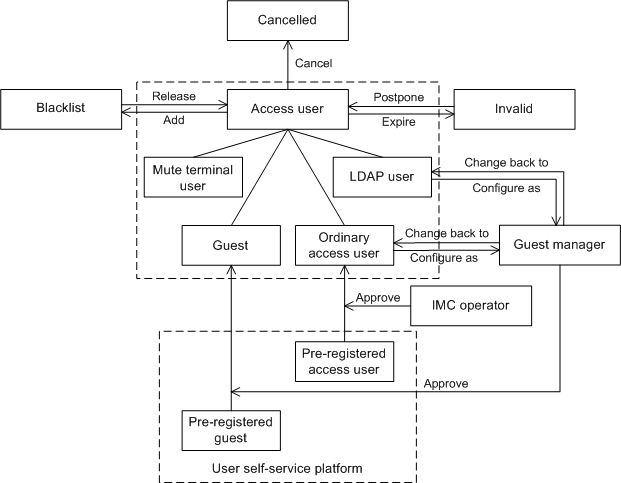
Determining appropriate access user type
Figure 88 shows the decisions used to determine the appropriate access user type.
Figure 88 Determining the access user type
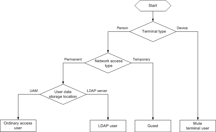
Determining authentication priorities
UAM performs MAC-based authentication for the following users:
· Mute terminal users who always use MAC addresses as their user names
· Ordinary access users, LDAP users, and guests who use MAC addresses as their user names
UAM also provides a transparent MAC authentication function to offer fast network access to ordinary access users and LDAP users. For more information about transparent MAC authentication, see "Transparent MAC authentication."
UAM uses operator-set authentication priorities to determine which authorization process to use.
Figure 89 shows the generic authentication process.
Figure 89 Generic authentication process
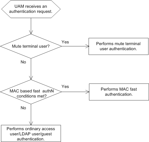
Managing ordinary access users
This section provides details about managing ordinary access users.
Accessing the access user list page
1. Click the User tab.
2. From the navigation tree, select Access User > All Access Users.
The list includes all access users.
|
|
NOTE: You can point to the Expand icon |
Access user list contents
¡ Account Name—Account name of the
access user. The account name is used for access user authentication and must
be unique in UAM. Account names with the Bind User
icon ![]() are
LDAP users. For information about LDAP user management, see "Managing LDAP users."
are
LDAP users. For information about LDAP user management, see "Managing LDAP users."
¡ User Name—Name of the platform user to which the access user is attached.
¡ User Group—User group to which the platform user belongs. Platform users with different rights are divided into multiple user groups for easy management.
¡ Creation Date—Date when the access user was created.
¡ Start Time—Date and time when the access user becomes valid. An empty field indicates that the access user is already valid.
¡ End Time—Date and time when the access user expires and becomes invalid. An empty field indicates that the access user never expires.
¡ Account Status—Options are Normal, Trial, Temporarily Cancelled, Unactivated, and Cancelled. Only accounts in Normal state can be authenticated.
- Trial—A user account that is not counted in the user accounts managed by a license.
- Temporarily Cancelled—An invalid account that is temporarily deleted.
- Unactivated—A preregistered account that is registered but is not activated. For more information about preregistering accounts, see "Preregistering access users." To activate an approved account, go to system parameter configuration. For more information, see "Configuring global system settings."
- Cancelled—An invalid account that is permanently deleted.
¡ Modify—Click the Modify icon ![]() to modify settings of
the access user.
to modify settings of
the access user.
Querying ordinary access users
UAM allows both basic and advanced queries.
· Basic query—For quick searches. Offers only four fields for search criteria.
· Advanced query—For more precise results than basic queries. Offers many fields for search criteria.
Basic query
1. Access the access user list page.
2. Click the Basic Query link on the upper right side of the All Access Users area.
You can perform a basic query if you see Advanced Query on the upper right side of the All Access Users area.
3. Specify one or more of the following query criteria:
¡ Account Name—Enter a partial or complete access account name. The access user uses the account name for authentication. For example, if you enter x, all account names that contain x are matched.
¡ User Name—Enter a partial or complete platform user name. For example, if you enter y, all user names that contain y are matched.
¡ User Group—Click the Select User Group icon ![]() to select a group in
the Select User Group window. You can select only
one user group for query.
to select a group in
the Select User Group window. You can select only
one user group for query.
¡ Service Name—Select Unapplied or an existing service from the list.
The query ignores empty fields.
4. Click Query. The list shows all access users that match the query criteria.
5. Click Reset to clear the query criteria. The list shows all access users in UAM.
Advanced query
1. Access the access user list page.
2. Click the Advanced Query link on the upper right side of the All Access Users area.
You can perform an advanced query if you see Basic Query on the upper right side of the Query Access Users area.
3. Specify one or more of the following query criteria:
¡ Account Name—Enter a partial or complete access user account name. The account name is for authentication. For example, if you enter x, all account names that contain x are matched.
¡ User Name—Enter a partial or complete platform user name. For example, if you enter y, all user names that contain y are matched.
¡ User Group—Click the Select User Group icon ![]() to select a group in
the Select User Group window. You can select only
one user group for query.
to select a group in
the Select User Group window. You can select only
one user group for query.
¡ Service Name—Select Unapplied or an existing service from the list.
¡ Account Status—Select the account state from the list. Options include Normal, Trial, Temporarily Cancelled, Unactivated, Cancelled, and Non-Cancelled. Only accounts in the Normal state can be authenticated.
- Trial—A user account that is not counted in the user accounts managed by a license.
- Temporarily Cancelled—An invalid account that is temporarily deleted.
- Unactivated—A preregistered account that is registered but is not activated. For more information about preregistering accounts, see "Preregistering access users." For more information about formal registration, see "Managing preregistered users." To activate an approved account, go to system parameter configuration. For more information, see "Configuring global system settings."
- Cancelled—An invalid account that is permanently deleted.
- Non-Cancelled—Normal, trial, temporarily cancelled, and unactivated users are all categorized as non-canceled users. To filter out cancelled accounts, select Non-Cancelled from the list.
¡ Identity Number—Enter a partial or complete identity number for the platform user associated with the access user. For example, if you enter z, all identity numbers that contain z are matched.
¡ Contact Address—Enter a partial or complete contact address for the platform user associated with the access user. For example, if you enter a, all contact addresses that contain a are matched.
¡ Creation Date From/To—Click the Calendar icon ![]() to select the
time range when the account was created, or enter the time range in YYYY-MM-DD format.
to select the
time range when the account was created, or enter the time range in YYYY-MM-DD format.
¡ Last Logoff From/To—Click the Calendar icon ![]() to select the
time range when the access user last logged off, or enter the time range in
YYYY-MM-DD format.
to select the
time range when the access user last logged off, or enter the time range in
YYYY-MM-DD format.
¡ Start Time From/To—Click the Calendar icon ![]() to select the
time range when the account becomes valid, or enter the time range in YYYY-MM-DD format.
to select the
time range when the account becomes valid, or enter the time range in YYYY-MM-DD format.
¡ End Time From/To—Click the Calendar icon ![]() to select the time range when the account expires, or enter the
time range in YYYY-MM-DD format.
to select the time range when the account expires, or enter the
time range in YYYY-MM-DD format.
¡ Email—Enter a partial or complete email address for the platform user associated with the access user. For example, if you enter com, all email addresses that contain com are matched.
¡ Port—Enter the last portion of the interface number to which the access user is bound. For example, if an access user is bound to port 3, both interface number 1/0/3 and interface number 2/0/3 match the port. UAM supports only an exact match for this field.
¡ Max. Concurrent Logins—Enter the upper limit of concurrent logins allowed for the access user. UAM supports only an exact match for this field.
¡ Max. Idle Time (Minutes)—Enter the maximum idle time allowed for the access user. UAM supports only an exact match for this field.
¡ Device IP Address Range From/To—Enter an IP address range for the access device to which the access user is bound. You must enter a complete IPv4 address in each field.
¡ Computer Name—Enter a partial or complete name of the computer to which the access user is bound. For example, if you enter a, all computer names that contain a are matched.
¡ User SSID—Enter a partial or complete SSID of the wireless network that the access user can access. For example, if you enter a, all SSIDs that contain a are matched.
¡ VLAN ID/Inner VLAN ID—Enter a VLAN ID or inner VLAN ID to which the access user is bound. UAM supports only an exact match for this field.
¡ Outer VLAN ID—Enter the outer VLAN ID to which the access user is bound. UAM supports only an exact match for this field.
¡ LDAP Synchronization Policy—Select the LDAP synchronization policy to which the access user is bound. This query criterion is effective on LDAP users only. For more information about the LDAP users, see "Managing LDAP users."
¡ LDAP User Status—Select the LDAP user state from the list. Options include Unknown, Existent, and Nonexistent. The Unknown option indicates that an LDAP user has not synchronized information from the LDAP server. The Existent option indicates that the LDAP server contains an LDAP user that is associated with the access user. The Nonexistent option indicates that the LDAP server does not contain any LDAP user that is associated with the access user. This query criterion is effective on LDAP users only. For more information, see "Managing LDAP users."
¡ User IP Address Range From/To—Enter an IP address range for the endpoint to which the access user is bound. You must enter a complete IPv4 address in each field.
¡ User MAC Address—Enter a partial or complete MAC address of the computer to which the access user is bound. The value can be in the format of XXXX-XXXX-XXXX, XX-XX-XX-XX-XX-XX, or XX:XX:XX:XX:XX:XX. For example, if you enter AA-BB, all MAC addresses that contain AA-BB are matched.
¡ Third-Party Authentication Users—Select Yes if the access user uses the third-party authentication, or select No if the access user does not use the third-party authentication.
¡ IMSI—Enter a partial or complete IMSI of the computer to which the access user is bound. For example, if you enter EF, all IMSIs that contain EF are matched.
¡ Device SN—Enter a partial or complete device sequence number bound to the access user. For example, if you enter EF, all device sequence numbers that contain EF are matched.
¡ Endpoint MAC Address—Enter a partial or complete MAC address of the smart device bound to the access user account. A complete MAC address must be in the format of XXXX-XXXX-XXXX, XX-XX-XX-XX-XX-XX, or XX:XX:XX:XX:XX:XX. For example, if you enter 00-ef, all MAC addresses that contain 00-ef are matched.
¡ Windows Domain—Enter a partial or complete name of the Windows domain to which the computer of the access user is bound. For example, if you enter a, all Windows domain names that contain a are matched.
¡ WLAN Cell Phone Number—Enter a partial or complete phone number to which the access user is bound. For example, if you enter 138, all phone numbers that contain 138 are matched. This field is displayed only when Third-Party Authentication System is enabled in the UAM system settings. For more information, see "Configuring the third-party authentication system."
¡ Device IPv6—Enter a partial or complete IPv6 address of the access device to which the access user is bound. For example, if you enter EF, all device IPv6 addresses that contain EF are matched. This field is displayed only when IPv6 is enabled in the UAM system settings.
¡ User IPv6 Address—Enter a partial or complete IPv6 address of the endpoint to which the access user is bound. For example, if you enter EF, all endpoint IPv6 addresses that contain EF are matched. This field is displayed only when IPv6 is enabled in the UAM system settings.
¡ Creator—Enter a partial or complete name of the operator that created the access user. The creator is $SYSTEM for third-party authentication users and users synchronized from LDAP servers based on an on-demand sync policy.
The query ignores empty fields.
4. Click Query. The list shows all access users that match the query criteria.
5. Click Reset to clear the query criteria. The list shows all access users in UAM.
Viewing ordinary access user details
1. Access the access user list page.
2. Click the account name of the access user you want to view.
The access user details page opens.
Basic Information area
· User Name—Name of the platform user to which the access user is attached.
· ID Number—Identity number of the platform user to which the access user is attached.
· Contact Address—Contact address of the platform user to which the access user is attached.
· Telephone—Telephone number of the platform user to which the access user is attached.
· Email—Email address of the platform user to which the access user is attached.
· User Group—User group to which the access user belongs. If the user group has a parent group or subgroups, this field displays the complete group hierarchy of the user group.
Access Information area
· Account Name—Unique account name of the access user. The account name is used for access user authentication. When an access user is blacklisted, the account name of the user is followed by Blacklisted Users.
· Account Status—Options are Normal, Trial, Temporarily Cancelled, Unactivated, and Cancelled. Only accounts in the Normal state can be authenticated.
¡ Trial—A user account that is not counted in the user accounts managed by a license.
¡ Temporarily Cancelled—An invalid account that is temporarily deleted.
¡ Unactivated—A preregistered user account that is registered but is not activated. For more information about preregistering accounts, see "Preregistering access users." For more information about formal registration, see "Managing preregistered users." To activate an approved account, go to system parameter configuration. For more information, see "Configuring global system settings."
¡ Cancelled—An invalid account that is permanently deleted.
· Allow User to Change Password—Displays Yes if the access user is allowed to change the login password in the self-service center or iNode client. This field displays No if the access user is prohibited from changing the login password. For more information, see "Using the user self-service."
· Enable Password Strategy—Displays Yes if the access user must comply with the password strategy when the user tries to change the password through the iNode client. This field displays No if password strategy is not used. An IMC administrator can change the login password of any access user regardless of whether a password strategy is used. For more information, see "Configuring the password strategy."
· Creation Date—Date when the access user was created.
· Modify Password at Next Login—Displays Yes if the access user must change the login password next time the user passes authentication. After the access user changes the login password as required, this field changes to No. This field displays No if the access user is not required to change the login password.
· Start Time—Date and time when the access user becomes valid. An empty field indicates that the access user is already valid.
· End Time—Date and time when the access user expires and becomes invalid. An empty field indicates that the access user never expires.
· Max. Idle Time (Minutes)—Maximum idle time that the access user is allowed. The access user is forcibly logged off when the idle time expires. An empty field indicates that the access user can always stay online.
· Max. Concurrent Logins—Upper limit of concurrent logins that the access user is allowed. An empty field indicates that the concurrent logins of the access user are not restricted.
· Availability—Indicates whether the access user is online.
· Last Logoff—Time when the access user last logged off.
· WLAN Cell Phone Number—Phone number to which the access user is bound. This field is displayed only when Third-Party Authentication System is enabled in the UAM system settings. For more information, see "Configuring the third-party authentication system."
· Login Message—Message delivered to the access user when the user passes authentication.
· Guest Manager Type—Value can be Guest Manager or Super Guest Manager. This parameter is displayed only when the access user is a guest manager or super guest manager. For more information, see "Managing guests."
Access Service area
The list includes all services that are assigned to the access user account.
· When Apply for Service by User Group is disabled, the area displays all services that are manually assigned to the account by operators.
· When Apply for Service by User Group is enabled, the area displays all services that UAM automatically assigns to the account according to the user group to which the account belongs.
For information about configuring Apply for Service by User Group, see "Configuring global system settings."
Access service list contents
· Service Name—Name of a service, which must be unique in UAM.
· Service Suffix—Identifies the name of the domain to be used for endpoint user authentication. For more information, see Table 19. The user name and service suffix entered for user authentication are closely related to the domain where the access device authenticates the user.
· Allocate IP—IP address assigned by the service to the access user. An empty field indicates that no IP address is assigned.
The commands listed in Table 19 are available on HP Comware devices. The commands used on other access devices can vary.
Table 19 Service suffix and other configurations
|
Authentication user name |
Authentication domain on the access device |
Commands configured on the access device |
Service suffix in UAM |
Username prefix conversion mode |
|
X@Y Y\X Y/X |
Y |
user-name-format with-domain |
Y |
Change to Suffix |
|
user-name-format without-domain |
None |
Remove |
||
|
X [Default Domain]\X [Default Domain]/X |
[Default Domain] (Default domain on the access device) |
user-name-format with-domain |
[Default Domain] |
Change to Suffix |
|
user-name-format without-domain |
None |
Remove |
When user names in Y\X or Y/X format do not exist in the access user list or the LDAP temporary user list, UAM automatically converts the user names. Names in Y\X or Y/X format are converted to the X@Y or X format according the username prefix conversion mode. For more information about the username prefix conversion mode, see "Configuring system parameters."
Transparent Authentication MAC Address Binding area
The Transparent Authentication MAC Address Binding area displays all endpoint MAC addresses that are bound to the access user account for transparent authentication.
· Service Name/MAC Address—Service name and MAC address that are bound to the account for transparent portal authentication.
· Transparent Authentication—Whether the MAC address is allowed to use the account and service for transparent portal authentication. The status can be Enabled or Disabled.
· Enabled/Disabled Time—When transparent authentication is enabled, this field indicates the time when the smart device MAC address was bound to the user and service. When transparent authentication is disabled, this field indicates the time when transparent authentication on smart devices was automatically or manually disabled.
Access Device Binding Information area
To pass authentication, the access user must meet all requirements of the access device bindings and terminal bindings. The query ignores empty fields.
· Device SN—Requires the access user to connect to the access device that has the specified sequence number.
· Port—Requires the access user to be connected through the specified port of the access device. The value is the last portion of an interface number. For example, if an access user is bound to port 3, both interface number 1/0/3 and interface number 2/0/3 match the port.
· Outer VLAN ID—Requires the access user's packets to carry the specified outer VLAN ID.
· VLAN ID/Inner VLAN ID—Requires the access user's packets to carry any of the specified VLAN IDs or inner VLAN IDs.
· User SSID—Requires the access user to connect to the network that uses any of the specified SSIDs.
· Device IP—Requires the access user to connect to the access device that uses any of the specified IPv4 addresses. Each entry on the list represents the IPv4 address of an access device bound to the access user. If a device has multiple IP addresses, use the IPv4 address of the corresponding access device in UAM.
· Device IPv6 Address—Requires the access user to connect to the access device that uses any of the specified IPv6 addresses. Each entry on the list represents the IPv6 address of an access device bound to the access user. If a device has multiple IPv6 addresses, use the IPv6 address of the corresponding access device in UAM. This field is displayed only when IPv6 is enabled in the UAM system settings.
Terminal Binding Information area
To pass authentication, the access user must meet all requirements of the access device bindings and terminal bindings. The query ignores empty fields.
· Computer Name—Requires the access user to connect from the specified computer.
· IMSI—Requires the access user endpoint to use the specified IMSI.
· Windows Domain—Requires the access user endpoint to join or log in to the specified domain.
· Terminal IP Address—Requires the access user endpoint to use any of the specified IPv4 address.
· Terminal MAC Address—Requires the access user endpoint to use any of the specified MAC address.
· Terminal IPv6 Address—Requires the access user endpoint to use any of the specified IPv6 addresses. This field is displayed only when IPv6 is enabled in the UAM system settings.
· IMEI—Requires the access user endpoint to use the specified IMEI.
Action menu
The Action menu is located to the right of the Access Account Info pane, and offers the following actions:
· Refresh—Refresh the detailed information about the access user.
· Modify—Modify the access user. For more information, see "Modifying an ordinary access user."
· Cancel Account—Delete the access user.
· Add to Blacklist—Add the access user to the blacklist. The link is displayed only when the access user is not blacklisted.
· Release from Blacklist—Release the access user from the blacklist. The link is displayed only when the access user is blacklisted.
· Authentication Failure Log—View the list of authentication failure logs for the access user. For more information, see "Managing authentication failure logs."
· Authentication Violation Log—View the list of authentication violation logs for the access user. For more information, see "Managing authentication violation logs."
· Access Details—View the list of access details for the access user. For more information, see "Managing access detail records."
· Security Log—View the list of security logs for the access user. This option is displayed only when EAD is deployed.
· View Internet Access Audit Logs—View the list of Internet access audit logs for the access user. This option is displayed only when EAD is deployed.
· MAC Address Entry—View the list of MAC addresses that are bound to the user account only for transparent authentication. This link is displayed only when transparent authentication in user endpoint settings is enabled on UAM. For more information about transparent MAC authentication, see "Configuring MAC/BYOD authentication."
· Basic User Info—View detailed information about the platform user to which the access user is attached.
· Send Password via SMS—Send an SMS message that is defined by an operator and contains the user name and password of the account, so the user can retrieve the password. To use this function, first configure the SMS settings in the IMC platform. For information about configuring SMS system parameters, see HPE Intelligent Management Center v7.3 Enterprise and Standard Platform Administrator Guide. For information about configuring the SMS message content, see "Delivering messages."
· Temporary Cancel—Cancel the account temporarily. The link is displayed only when the account is in Normal state.
· Undo TempCancel—Change the account to the Normal state. The link is displayed only when the account is in Temporarily Cancelled state.
· Approve Trial—Approve the account. The link is displayed only when the account is in Trial state.
Adding an ordinary access user
1. Access the access user list page.
2. Click Add.
The Add Access User page opens.
3. Configure the access information:
¡ User Name—Configure the name of the platform user to which the access user is attached. In the Window that opens, click Select to select an existing platform user, or click Add User to add a new platform user.
¡ Account Name—Enter the account name of an access user. The account name must be unique in UAM, and is used for access user authentication. An account name can contain letters, numbers, spaces, hyphens (-), underscores (_), and dots (.).
¡ Trial Account—Sets the access user as a trial account. You can also configure the fast access user or computer user as a trial account. Trial accounts are excluded from the user accounts managed by a license, and cannot pass authentication. Trial accounts are typically configured by batch operations. For more information, see "Importing accounts in batches."
¡ Default BYOD User—Sets the access user as the BYOD anonymous user. This field is displayed only when UAM has no BYOD anonymous user created. When this field is selected, the Account Name field is automatically populated by byodanonymous and the Computer User, MAC Authentication User, and Fast Access User fields are hidden. The user account is for anonymous MAC authentication. For more information, see "Anonymous MAC authentication."
¡ MAC Authentication User—Sets the access user as a MAC authentication user who uses the MAC address as the user name and password for network access. When this field is selected, the following fields are hidden:
- Default BYOD User
- Computer User
- Fast Access User
- Password
- Confirm Password
- Allow User to Change Password
- Enable Password Strategy
- Modify Password at Next Login
- Max. Concurrent Logins
|
|
TIP: These parameters are hidden to simplify the user configuration page. Except Default BYOD User, Computer User, and Fast Access User, the hidden parameters are still available for the MAC authentication user. You can display and configure the parameters when modifying the user. |
¡ Computer User—Sets the access user as the computer user. This field is displayed only when UAM has no computer user created. When this field is selected, the Account Name field is automatically populated by computer and the following fields are hidden:
- Default BYOD User
- MAC Authentication User
- Fast Access User
- Password
- Confirm Password
- Allow User to Change Password
- Enable Password Strategy
- Modify Password at Next Login
After the computer user is created in UAM, the user can create an 802.1X connection with the PC authentication mode in the iNode client.
¡ Fast Access User—Sets the access user as the fast access user. This field is displayed only when UAM has no fast access user created. When this field is selected, the Account Name field is automatically populated by anonymous and the following fields are hidden:
- Default BYOD User
- MAC Authentication User
- Computer User
- Password
- Confirm Password
- Allow User to Change Password
- Enable Password Strategy
- Modify Password at Next Login
After the fast access user is created in UAM, the user can create a quick authentication connection in the iNode client for authentication.
¡ Password—Enter the access user password.
¡ Confirm Password—Enter the password again.
¡ Allow User to Change Password—Enables the access user to change the password in the self-service center or iNode client.
¡ Enable Password Strategy—Enables the password control strategy for the access user. The strategy requires that the access user must meet certain requirements when the user tries to change the password through the iNode client. An IMC administrator can change the password of any access user regardless of whether a password strategy is used. This option is available only when the Allow User to Change Password option is selected.
¡ Modify Password at Next Login—Requires that the access user must change the password next time the user passes authentication. This option can be configured only when the Enable Password Strategy option is selected. After the access user changes the password, this parameter is automatically unselected. Transparent portal authentication does not take effect if the access user does not change the password as required by the Modify Password at Next Login option. In this situation, the user account name cannot be bound with the MAC address of the endpoint used for network access.
¡ Start Time—Enter the date and time when the access user becomes valid. If you leave this field empty, the access user becomes valid immediately after being created.
¡ End Time—Enter the date and time when the access user expires and becomes invalid. An empty field indicates that the access user never expires.
¡ Max. Idle Time (Minutes)—Enter the maximum idle time permitted for an online user. When the time expires, the user is forcibly logged off. An empty field indicates that the access user can always be online without performing any operations.
¡ Max. Concurrent Logins—Enter the maximum number of concurrent online users of the account. An empty field indicates no restrictions on the number of concurrent online users using the account.
¡ WLAN Cell Phone Number/WLAN Password/Confirm Password—Enter the phone number and password to which the access user is bound. This field is displayed only when Third-Party Authentication System is enabled in the UAM system settings. When this function is enabled, UAM sends the phone number and password for second authentication by the third-party authentication system. For information about third-party system authentication, see "Configuring the third-party authentication system." For information about phone number configuration restrictions, see "Configuring the cell phone number ranges."
¡ Login Message—Enter the message to be displayed on the user endpoint when the user passes authentication.
4. In the Access Service area, select the access services on the access service list. You can select multiple services with different suffixes for the access user.
When Apply for Service by User Group is enabled, UAM hides the Access Service area and automatically assigns services of each user group to their respective users. For information about configuring Apply for Service by User Group, see "Configuring global system settings."
The access service list contains the following parameters:
¡ Service Name—Name of the access service, which must be unique in UAM.
¡ Service Suffix—Identifies the name of the domain to be used for endpoint user authentication. For more information, see Table 20. The user name and service suffix entered for user authentication are closely related to the domain where the access device authenticates the user.
¡ Default Security Policy—Default security policy in the service. This parameter is displayed only when the EAD component is installed.
¡ Status—Whether an access service can be applied for. Unavailable services do not appear on the access service list.
¡ Allocate IP—IP address that the access service allocates to the user. An empty field indicates that the access service does not allocate any IP address.
The commands in Table 20 are available on HP Comware devices. The commands used on other access devices may vary.
Table 20 Service suffix and other configurations
|
Authentication user name |
Authentication domain on the access device |
Commands configured on the access device |
Service suffix in UAM |
Username prefix conversion mode |
|
X@Y Y\X Y/X |
Y |
user-name-format with-domain |
Y |
Change to Suffix |
|
user-name-format without-domain |
None |
Remove |
||
|
X [Default Domain]\X [Default Domain]/X |
[Default Domain] (Default domain on the access device) |
user-name-format with-domain |
[Default Domain] |
Change to Suffix |
|
user-name-format without-domain |
None |
Remove |
When user names in Y\X or Y/X format do not exist in the access user list or the LDAP temporary user list, UAM automatically converts the user names. Names in Y\X or Y/X format are converted to the X@Y or X format according the username prefix conversion mode. For more information about the username prefix conversion mode, see "Configuring system parameters."
5. Configure the access device or terminal binding information.
The binding parameters in this area take effect only when they are selected in the Authentication Binding Information area of the selected access policies. For example, the Device IP parameter applies to access policies with the Bind Access Device IP option selected.
If you select a binding option for an access policy without specifying a value for the parameter in the Access Device Binding Information area, UAM automatically acquires the binding information for the access policy when a user first passes authentication.
To pass authentication, the access user must meet all requirements of the access device bindings and terminal bindings.
¡ Device SN—Enter the sequence number of the access device to which the access user is connected.
¡ Port—Enter the port through which the access user is connected to the access device. The value is the last portion of an interface number. For example, if an access user is bound to port 3, both interface number 1/0/3 and interface number 2/0/3 match the port.
¡ Outer VLAN ID—Enter the outer VLAN ID that is contained in the access user's packets.
¡ VLAN ID/Inner VLAN ID—Enter a list of VLAN IDs or inner VLAN IDs that can be contained in the access user's packets.
¡ User SSID—Enter a list of SSIDs to which the access user can be connected.
¡ Device IP—Enter a list of IPv4 address for the access devices to be bound to the access user. Each entry on the list represents the IP address of an access device bound to the access user. If a device has multiple IP addresses, use the IP address of the corresponding access device in UAM.
¡ Device IPv6 Address—Enter a list of IPv6 address for the access devices to be bound to the access user. Each entry on the list represents the IPv6 address of an access device bound to the access user. If a device has multiple IPv6 addresses, use the IPv6 address of the corresponding access device in UAM.
¡ Computer Name—Enter the name of the computer to be bound to the access user.
¡ IMSI—Enter the IMSI of the endpoint to be bound to the access user.
¡ Windows Domain—Enter the name of the Windows domain that the user endpoint must join or log in to.
¡ Terminal IP Address—Enter a list of IPv4 addresses or IPv4 address ranges for the endpoints from which the access user can access the network. The IPv4 address ranges must be specified in the format X.X.X.X-X.X.X.X.
¡ Terminal MAC Address—Enter a list of MAC addresses for the endpoints from which the access user can access the network.
¡ Terminal IPv6 Address—Enter a list of IPv6 addresses for the endpoints from which the access user can access the network. This field is displayed only when IPv6 is enabled in the UAM system settings.
¡ IMEI—Enter the IMEI of the endpoint to be bound to the access user.
6. Click OK or OK & Print.
If you click OK, UAM adds the access user and displays the access user list.
If you click OK & Print, a print preview window opens. You can view the access user information, and then click Print at the top of the window.
Bulk importing ordinary access users
1. Access the access user list page.
2. Click Batch Import.
The Import Accounts in Batches page opens. For subsequent steps, see "Importing accounts in batches."
Bulk exporting ordinary access users
1. Access the access user list page.
2. Select one or more access user accounts you want export.
3. Click More and select Batch Export from the shortcut menu.
The Export File Format page opens.
4. Select the format of the file to store the exported account information from the File Format list. Options are TXT and CSV. You can open a .csv file in Microsoft Excel.
5. Select a column separator to use in the .txt export file from the Column Separator list. Options are Space, TAB, comma (,), colon (:), pound sign (#), and dollar sign ($). This field is displayed only when TXT is selected in the File Format list.
6. Select the way in which the exported passwords are stored from the Export Plain Password list. If you select Yes, all user passwords are exported in plain text. If you select No, all user passwords are exported in encrypted format.
7. Configure the account parameters to be exported.
By default, the exported account information includes Account Name, User Name, User Group, and Expiration Time. UAM also provides you with the ability to export one or more of the following parameters:
¡ Password
¡ Identity Number
¡ Telephone
¡ Contact Address
¡ Account Status
¡ Creation Time
¡ Access Device IP
¡ Access Device IPv6 Address
¡ Port
¡ VLAN ID/Inner VLAN ID
¡ Outer VLAN ID
¡ User SSID
¡ User IP
¡ User IPv6
¡ User MAC
¡ Max. Concurrent Logins
¡ Max. Idle Time (Minutes)
¡ Access Service List
¡ Computer Name
¡ Windows Domain
¡ Login Message
¡ Device SN
¡ IMSI
¡ IMEI
¡ WLAN Cell Phone Number/WLAN Password
|
|
NOTE: Access Device IPv6 Address and User IPv6 appear only when IPv6 is enabled in system parameters. WLAN Cell Phone Number/WLAN Password is displayed only when Third-Party Authentication System is enabled. |
All parameters on the Output List will be exported to the file. You can perform the following operations:
¡ Select
a parameter on the Option List and click the Copy icon ![]() to move it to the Output List.
to move it to the Output List.
¡ Click
the Copy all icon ![]() to move all parameters
from the Option List to the Output
List.
to move all parameters
from the Option List to the Output
List.
¡ Select
an undesired parameter on the Output List and click
the Remove icon ![]() to move it back to the
Option List.
to move it back to the
Option List.
¡ Click
the Remove all icon ![]() to move all parameters
from the Output List to the Option
List.
to move all parameters
from the Output List to the Option
List.
You can sort the Output List by performing the following operations:
¡ Click
the Top icon ![]() to move a selected
parameter to the top of the Output List.
to move a selected
parameter to the top of the Output List.
¡ Click
the Up icon ![]() to move up a selected
parameter in the Output List.
to move up a selected
parameter in the Output List.
¡ Click
the Down icon ![]() to move down a
selected parameter in the Output List.
to move down a
selected parameter in the Output List.
¡ Click
the Bottom icon ![]() to move a selected
parameter to the bottom of the Output List.
to move a selected
parameter to the bottom of the Output List.
8. Click OK.
UAM exports information about the selected access user accounts and displays the export results.
9. Click Download to view the export file or save it to another place.
By default, the export file is stored at the tmp directory in the IMC installation path on the IMC master server and is named in the format of exportAccountexport-time.
Approving trial accounts
Trial accounts are excluded from the user accounts managed by a license, and cannot pass authentication. Trial accounts are typically configured by batch operations. For more information, see "Importing accounts in batches."
Trial accounts become normal accounts after they are approved by an operator.
Approving trial accounts on the access user list page
1. Access the access user list page.
2. Select one or more access accounts in Trial state.
3. Click More and select Approve Trial from the shortcut menu.
UAM changes the selected accounts to normal accounts, and then displays the number of successfully approved accounts and the number of failures. If failures exist, you can click Download to load or view the failure reasons in the operation log.
Approving a trial account on the access user details page
1. Access the access user list page.
2. Click the name of an access account in Trial state.
The access user details page opens.
3. Click Approve Trial on the Action menu on the right.
A confirmation dialog box opens.
4. Click OK.
Modifying an ordinary access user
1. Access the access user list page.
2. Click the Modify icon ![]() for the access user you want to modify.
for the access user you want to modify.
The Modify Access User page opens.
3. Modify parameters for the access user account. The user name and account name cannot be modified. For more information, see "Adding an ordinary access user."
4. Click OK.
Bulk modifying ordinary access users
1. Access the access user list page.
2. Select one or more account names you want to modify.
The Modify Account page opens. For subsequent steps, see "Querying and maintaining accounts in batches."
Temporarily canceling normal accounts
Operators can temporarily cancel access user accounts that will not access the network for a period of time. Temporarily cancelled accounts cannot pass authentication. However, they are counted in the user accounts managed by a license, and can be easily restored to normal accounts.
Temporarily canceling normal accounts on the access user list page
1. Access the access user list page.
2. Select one or more access accounts in Normal state.
3. Click More and select Temporary Cancel from the shortcut menu.
UAM changes the selected accounts to temporarily cancelled accounts, and then displays the number of successfully cancelled accounts and the number of failures. If failures exist, you can click Download to load or view the failure reasons in the operation log.
Temporarily canceling a normal account on the access user details page
1. Access the access user list page.
2. Click the name of an access account in Normal state.
The access user details page opens.
3. Click Temporary Cancel on the Action menu on the right.
A confirmation dialog box opens.
4. Click OK.
Restoring temporarily cancelled accounts to normal accounts
Operators can restore temporarily cancelled accounts to normal accounts. Temporarily cancelled accounts cannot pass authentication, but they are counted in the user accounts managed by a license.
Restoring temporarily cancelled accounts on the access user list page
1. Access the access user list page.
2. Select one or more access accounts in Temporarily Cancelled state.
3. Click More and select Undo TempCancel from the shortcut menu.
UAM changes the selected accounts to normal accounts, and then displays the number of successfully restored accounts and the number of failures. If failures exist, you can click Download to load or view the failure reasons in the operation log.
Restoring a temporarily cancelled account on the access user details page
1. Access the access user list page.
2. Click the name of an access account in Temporarily Cancelled state.
The access user details page opens.
3. Click Undo TempCancel on the Action menu on the right.
A confirmation dialog box opens.
4. Click OK.
Deleting ordinary access users
1. Access the access user list page.
2. Select one or more account names you want to delete.
3. Click Cancel Accounts.
The Cancel Accounts page contains a Delete Platform Users option.
¡ Do not select the Delete Platform Users option if you want to delete the selected access users without deleting the platform users to which the access users are attached.
¡ Select the Delete Platform Users option if you want to delete the selected access users and the platform user to which the access users are attached. However, UAM does not delete the platform user if one or more access users are still attached to it.
4. Click OK.
Adding ordinary access users to the blacklist
A blacklisted user cannot pass authentication for network access. For more information about the blacklist, see "Managing blacklisted users."
Blacklisting users on the access user list page
1. Access the access user list page.
2. Select one or more account names you want to add to the blacklist.
3. Click Add to Blacklist.
A confirmation dialog box opens.
4. Click OK.
Blacklisting users on the access user details page
1. Access the access user list page.
2. Click the account name of the access user you want to add to the blacklist.
3. Click Add to Blacklist in the Action menu on the right.
A confirmation dialog box opens.
Releasing ordinary access users from the blacklist
When you release a user from the blacklist, the user can pass authentication for network access. For more information about the blacklist, see "Managing blacklisted users."
Releasing a user from the blacklist on the access user details page
1. Access the access user list page.
2. Click the account name of the access user you want to release from the blacklist.
3. Click Release from Blacklist in the Action menu on the right.
A confirmation dialog box opens.
4. Click OK.
Releasing users from the blacklist on the blacklist user management page
To release users from the blacklist on the blacklist user management page:
1. Click the User tab.
2. From the navigation tree, select Access User > Blacklisted User.
The list includes all blacklisted users.
3. Select one or more account names you want to release from the blacklist.
4. Click Release from Blacklist.
A confirmation dialog box opens.
5. Click OK.
Applying for services for ordinary access users
When Apply for Service by User Group is enabled, the Apply for Service button does not appear in the access user list area, and operators cannot manually apply for services for access users. For information about configuring Apply for Service by User Group, see "Configuring global system settings."
To apply for services for ordinary access users:
1. Access the access user list page.
2. Select one or more account names for which you want to apply for services.
The Service List page opens. For subsequent operation steps, see "Querying and maintaining accounts in batches."
Canceling a service for ordinary access users
When Apply for Service by User Group is enabled, the Cancel Service button does not appear in the access user list area, and operators cannot manually cancel services for access users. For information about configuring Apply for Service by User Group, see "Configuring global system settings."
You cannot cancel a service for the online user if the service is being used by that user.
To cancel a service for ordinary access users:
1. Access the access user list page.
2. On the query area, select a service from the Service Name list.
3. Select one or more account names for which you want to cancel the applied service.
4. Click Cancel Service.
A confirmation dialog box opens.
5. Click OK.
Regrouping ordinary access users
1. Access the access user list page.
2. Select one or more access users for which you want to change their user groups.
3. Click More and select Regroup from the shortcut menu.
The Regroup page opens.
4. Select the user group that you want to move the selected access users to.
A confirmation dialog box opens.
5. Click OK.
Managing preregistered users
Endpoint users can preregister access user accounts in the self-service center. For more information, see "Preregistering access users."
Preregistered users cannot be authenticated. Operators can turn them into ordinary access users through formal registration.
Accessing the preregistered user list page
1. Click the User tab.
2. From the navigation tree, select Access User > Preregistered User.
The list includes all preregistered users.
Preregistered user list contents
¡ Account Name—Account name of the preregistered user. Click the name to view its details.
¡ User Name—Real name of the preregistered user.
¡ Registration Date—Date when the user was preregistered.
¡ Expiration Time—Time when the preregistered user expires and is deleted from the preregistered user list.
¡ Register—Click the Register icon ![]() to change the preregistered user into an ordinary access user.
to change the preregistered user into an ordinary access user.
Querying preregistered users
UAM provides basic query and advanced query. Basic query criteria include several key parameters for quick search. Advanced query offers various query criteria for precise match.
Basic query
1. Access the preregistered user list page.
2. On the Query Preregistered Users area, click the Basic Query link at the upper right corner.
You can perform a basic query if you see Advanced Query on the upper right side of the Query Preregistered Users area.
3. Specify one or more of the following query criteria:
¡ User Name—Enter a partial or complete name of the preregistered user. For example, if you enter jack, all user names that contain jack are matched.
¡ Account Name—Enter the account name of the preregistered user. For example, if you enter jack, all account names that contain jack are matched.
¡ Registered From/To—Click the Calendar icon ![]() to select the
time range when the user was preregistered, or enter the time range in
YYYY-MM-DD format.
to select the
time range when the user was preregistered, or enter the time range in
YYYY-MM-DD format.
The query ignores empty fields.
4. Click Query.
The list includes all preregistered users matching the query criteria.
Advanced query
1. Access the preregistered user list page.
2. On the Query Preregistered Users area, click the Advanced Query link at the upper right corner.
You can perform an advanced query if you see Basic Query on the upper right side of the Query Preregistered Users area.
3. Specify one or more of the following query criteria:
¡ Account Name—Enter a partial or complete account name of the preregistered user. For example, if you enter jack, all account names that contain jack are matched.
¡ User Name—Enter a partial or complete real name of the preregistered user. For example, if you enter jack, all user names that contain jack are matched.
¡ ID Number—Enter a partial or complete identity number of the preregistered user. For example, if you enter 123, all ID numbers that contain 123 are matched.
¡ Contact Address—Enter a partial or complete contact address of the preregistered user. For example, if you enter lab321, all contact addresses that contain lab321 are matched.
¡ Registered From/To—Click the Calendar icon ![]() to select the
time range when the user was preregistered, or enter the time range in
YYYY-MM-DD format.
to select the
time range when the user was preregistered, or enter the time range in
YYYY-MM-DD format.
¡ Email—Enter a partial or complete email address of the preregistered user. For example, if you enter hp.com, all email addresses that contain hp.com are matched.
The query ignores empty fields.
4. Click Query.
The list includes all preregistered users matching the query criteria.
5. To clear the query criteria, click Reset.
The list includes all preregistered users.
Viewing preregistered user details
1. Access the preregistered user list page.
2. Click the account name of the preregistered user you want to view.
The preregistered user details page opens.
Basic Information area
¡ User Name—Name of the preregistered user.
¡ ID Number—Identity number of the preregistered user.
¡ Contact Address—Contact address of the preregistered user.
¡ Telephone—Telephone number of the preregistered user.
¡ Email—Email address of the preregistered user.
Additional Information area
This area display additional information about the preregistered user.
Access Account Information area
¡ Account Name—Account name of the preregistered user.
¡ User IP—IPv4 addresses or IPv4 address ranges of the preregistered user.
¡ MAC Address—MAC addresses of the preregistered user.
¡ User IPv6 Address—IPv6 addresses of the preregistered user. This field is displayed only when IPv6 is enabled in the UAM system settings.
¡ Registration Date—Date when the user was preregistered.
3. Click Back to return to the preregistered user list page.
Registering as an ordinary access user
1. Access the preregistered user list page.
2. Click the Register icon ![]() for the
preregistered user you want to change into an ordinary
access user.
for the
preregistered user you want to change into an ordinary
access user.
The Register page opens.
3. Configure the following basic information:
¡ User Name—Enter the name of the endpoint user or leave the preregistered user name unchanged.
¡ ID Number—Enter the identity number of the endpoint user or leave the preregistered ID number unchanged.
¡ Contact Address—Enter the contact address of the endpoint user or leave the preregistered contact address unchanged.
¡ Telephone—Enter the telephone number of the endpoint user or leave the preregistered telephone number unchanged.
¡ Email—Enter the email address of the endpoint user or leave the preregistered email address unchanged.
¡ User Group—Click the Select User Group icon ![]() to select a group in
the Select User Group window. You can select only
one user group.
to select a group in
the Select User Group window. You can select only
one user group.
4. Configure the access information:
¡ Account Name—Enter the account name of the access user or leave the preregistered account name unchanged. The account name must be unique in UAM, and can contain letters, numbers, spaces, hyphens (-), underscores (_), and dots (.).
¡ Password/Confirm Password—Enter the access user password and confirm the password. If you leave the fields blank, you use the preregistered password.
¡ Allow User to Change Password—Enables the access user to change the password in the self-service center or iNode client.
¡ Enable Password Strategy—Enables password control strategy for the access user. The strategy requires that the access user meet certain requirements when trying to change the password through the iNode client. An IMC administrator can change the password of any access user regardless of whether a password strategy is used. This option is available only when the Allow User to Change Password option is selected.
¡ Modify Password at Next Login—Requires that the access user must change the password the next time the user passes authentication. This option can be configured only when the Enable Password Strategy option is selected. After the access user changes the password, this parameter is automatically unselected.
¡ Start Time—Enter the date and time when the access user becomes valid. Leave this field empty if you want the access user to become valid immediately after being created.
¡ End Time—Enter the date and time when the access user expires and becomes invalid. An empty field indicates that the access user never expires.
¡ Max. Idle Time (Minutes)—Enter the maximum idle time permitted for an online user. When the time expires, the user is forcibly logged off. An empty field indicates that the access user can always be online without performing any operations.
¡ Login Message—Enter the message to be displayed on the user endpoint when the user passes authentication.
¡ Max. Concurrent Logins—Enter the maximum number of concurrent online users of the account. An empty field indicates no restriction on the number of concurrent online users using the account.
¡ WLAN Cell Phone Number/WLAN Password/Confirm Password—Phone number and password to which the access user is bound. These fields appear only when Third-Party System Authentication is enabled in the UAM system settings. When this function is enabled, UAM sends the phone number and password for second authentication by the third-party authentication system. For more information about third-party system authentication, see "Configuring the third-party authentication system." For more information about phone number configuration restrictions, see "Configuring the cell phone number ranges."
5. Configure the access services.
When Apply for Service by User Group is enabled, UAM hides this area and automatically assigns services of each user group to their respective users. For information about configuring Apply for Service by User Group, see "Configuring global system settings."
Select the access services on the access service list. You can select multiple services with different suffixes for the access user.
The access service list contains the following parameters:
¡ Service Name—Name of the access service, which must be unique in UAM.
¡ Service Suffix—Identifies the name of the domain to be used for endpoint user authentication. For more information, see Table 21. The user name and service suffix entered for user authentication are closely related to the domain where the access device authenticates the user.
The commands listed in Table 21 are available on HP Comware devices. The commands used on other access devices can vary.
Table 21 Service suffix and other configurations
|
Authentication user name |
Authentication domain on the access device |
Commands configured on the access device |
Service suffix in UAM |
Username prefix conversion mode |
|
X@Y Y\X Y/X |
Y |
user-name-format with-domain |
Y |
Change to Suffix |
|
user-name-format without-domain |
None |
Remove |
||
|
X [Default Domain]\X [Default Domain]/X |
[Default Domain] (Default domain on the access device) |
user-name-format with-domain |
[Default Domain] |
Change to Suffix |
|
user-name-format without-domain |
None |
Remove |
6. Configure the access device binding information.
The binding parameters in this area take effect only when they are selected in the Authentication Binding Information area of the selected services. For example, the Device IP parameter is effective to the services with the Bind Access Device IP option selected.
If you select a binding option for a service but do not specify a value for the parameter in the Access Device Binding Information area, UAM automatically acquires the binding information for the service when each user first passes authentication.
To pass authentication, the access user must meet all requirements of the access device bindings and terminal bindings.
¡ Device SN—Enter the sequence number of the access device to which the access user is connected.
¡ Port—Enter the port through which the access user is connected to the access device. The value is the last portion of an interface number. For example, if an access user is bound to port 3, both interface number 1/0/3 and interface number 2/0/3 match the port.
¡ Outer VLAN ID—Enter the outer VLAN ID that is contained in the access user's packets.
¡ VLAN ID/Inner VLAN ID—Enter a list of VLAN IDs or inner VLAN IDs that can be contained in the access user's packets.
¡ User SSID—Enter a list of SSIDs to which the access user can be connected.
¡ Device IP—Enter a list of IPv4 address for the access devices to be bound to the access user. Each entry on the list represents the IP address of an access device bound to the access user. If a device has multiple IP addresses, use the IP address of the corresponding access device in UAM.
¡ Device IPv6 Address—Enter a list of IPv6 address for the access devices to be bound to the access user. Each entry on the list represents the IPv6 address of an access device bound to the access user. If a device has multiple IPv6 addresses, use the IPv6 address of the corresponding access device in UAM.
7. Configure the terminal binding information.
The binding parameters in this area take effect only when they are selected in the Authentication Binding Information area of the selected services. For example, the Computer Name parameter is effective to the services with the Bind Computer Name option selected.
If you select a binding option for a service but do not specify a value for the parameter in the Access Device Binding Information area, UAM automatically acquires the binding information for the service when each user first passes authentication.
To pass authentication, the access user must meet all requirements of the access device bindings and terminal bindings.
¡ Computer Name—Enter the name of the computer to be bound to the access user.
¡ IMSI—Enter the IMSI of the endpoint to be bound to the access user.
¡ Windows Domain—Enter the name of the domain that the user endpoint must join.
¡ Terminal IP Address—Enter a list of IPv4 addresses or IPv4 address ranges for the endpoints from which the access user can access the network. The IPv4 address ranges must be specified in the format X.X.X.X-X.X.X.X.
¡ Terminal MAC Address—Enter a list of MAC addresses for the endpoints from which the access user can access the network.
¡ Terminal IPv6 Address—Enter a list of IPv6 addresses for the endpoints from which the access user can access the network. This field is displayed only when IPv6 is enabled in the UAM system settings.
¡ IMEI—Enter the IMEI of the endpoint to be bound to the access user.
8. Click OK.
The preregistered user changes into an ordinary access user, and is added to the access user list.
Bulk registering as ordinary access users
You can bulk register preregistered users as ordinary access users and configure their common parameters. Bulk registration does not change the basic information about the preregistered users, such as the user name, telephone, and user IP.
To bulk register ordinary access users:
1. Access the preregistered user list page.
2. Select the preregistered users you want to change into ordinary access users.
3. Click Register.
The Register page opens.
4. Configure the access information:
¡ User Group—Click the Select User Group icon ![]() to select a group in the Select User Group
window. You can select only one user group.
to select a group in the Select User Group
window. You can select only one user group.
¡ Allow User to Change Password—Enables the access users to change the password in the self-service center or iNode client.
¡ Enable Password Strategy—Enables the password control strategy for the access users. The strategy requires that the access users meet certain requirements when trying to change the password through the iNode client. An IMC administrator can change the password of any access user regardless of whether a password strategy is used. This option is available only when the Allow User to Change Password option is selected.
¡ Modify Password at Next Login—Requires that each access user must change the password next time the user passes authentication. This option can be configured only when the Enable Password Strategy option is selected. After the access user changes the password, this parameter is automatically unselected.
¡ Start Time—Enter the date and time when the access user becomes valid. Leave this field empty if you want the access user to become valid immediately after being created.
¡ End Time—Enter the date and time when the access user expires and becomes invalid. An empty field indicates that the user's access never expires.
¡ Max. Idle Time (Minutes)—Enter the maximum idle time permitted for each online user. When the time expires, the user is forcibly logged off. An empty field indicates that the access users can always be online without performing any operations.
¡ Login Message—Enter the message to be displayed on user endpoints when users pass authentication.
¡ Max. Concurrent Logins—Enter the maximum number of concurrent online users of the same account. An empty field does not restrict the number of concurrent online users using the same account.
5. Configure the access services.
When Apply for Service by User Group is enabled, UAM hides this area and automatically assigns services of each user group to their respective users. For information about configuring Apply for Service by User Group, see "Configuring global system settings."
Select the access services on the access service list. You can select multiple services with different suffixes for each access user.
The access service list contains the following parameters:
¡ Service Name—Name of the access service, which must be unique in UAM.
¡ Service Suffix—Identifies the name of the domain to be used for endpoint user authentication. For more information, see Table 22. The user name and service suffix entered for user authentication are closely related to the domain where the access device authenticates the user.
The commands listed in Table 22 are available on HP Comware devices. The commands used on other access devices can vary.
Table 22 Service suffix and other configurations
|
Authentication user name |
Authentication domain on the access device |
Commands configured on the access device |
Service suffix in UAM |
Username prefix conversion mode |
|
X@Y Y\X Y/X |
Y |
user-name-format with-domain |
Y |
Change to Suffix |
|
user-name-format without-domain |
None |
Remove |
||
|
X [Default Domain]\X [Default Domain]/X |
[Default Domain] (Default domain on the access device) |
user-name-format with-domain |
[Default Domain] |
Change to Suffix |
|
user-name-format without-domain |
None |
Remove |
6. Configure the access device binding information.
The binding parameters in this area take effect only when they are selected in the Authentication Binding Information area of the selected services. For example, the Device IP parameter is effective to the services with the Bind Access Device IP option selected.
If you select a binding option for a service without specifying a value for the parameter in the Access Device Binding Information area, UAM automatically acquires the binding information for the service when each user first passes authentication.
To pass authentication, the access user must meet all requirements of the access device bindings and terminal bindings.
¡ Device SN—Enter the sequence number of the access device to which the access user is connected.
¡ Port—Enter the port through which the access user is connected to the access device. The value is the last portion of an interface number. For example, if an access user is bound to port 3, both interface number 1/0/3 and interface number 2/0/3 match the port.
¡ Outer VLAN ID—Enter the outer VLAN ID that is contained in the access user's packets.
¡ VLAN ID/Inner VLAN ID—Enter a list of VLAN IDs or inner VLAN IDs that can be contained in the access user's packets.
¡ User SSID—Enter a list of SSIDs to which the access user can be connected.
¡ Device IP—Enter a list of IPv4 address for the access devices to be bound to the access user. Each entry on the list represents the IP address of an access device bound to the access user. If a device has multiple IP addresses, use the IP address of the corresponding access device in UAM.
¡ Device IPv6 Address—Enter a list of IPv6 address for the access devices to be bound to the access user. Each entry on the list represents the IPv6 address of an access device bound to the access user. If a device has multiple IPv6 addresses, use the IPv6 address of the corresponding access device in UAM.
7. Configure the terminal binding information.
The binding parameters in this area take effect only when they are selected in the Authentication Binding Information area of the selected services. For example, the Computer Name parameter is effective to the services with the Bind Computer Name option selected.
If you select a binding option for a service but do not specify a value for the parameter in the Access Device Binding Information area, UAM automatically acquires the binding information for the service when each user first passes authentication.
To pass authentication, the access user must meet all requirements of the access device bindings and terminal bindings.
¡ Windows Domain—Enter the name of the domain that the user endpoint must join or log in to.
8. Click OK.
The preregistered users change into ordinary access users and appear on the access user list.
Deleting preregistered users
When a preregistered user is deleted from the preregistered user list, you cannot register it as an ordinary access user.
To delete one or more preregistered users:
1. Access the preregistered user list page.
2. Select one or more preregistered users you want to delete.
3. Click Delete.
A confirmation dialog box opens.
4. Click OK.
Managing mute terminal users
Network terminals such as IP phones and printers do not offer authentication pages and cannot actively initiate authentication requests. They are categorized as mute terminals. To enable them to access the network, you can configure mute terminal users in UAM.
To reduce the workload of configuring mute terminal users separately, the following workflow applies:
· Configure a list of permitted MAC address ranges for mute terminals, and configure UAM to generate a set of predefined accounts.
· When a mute terminal is connected to the network, UAM checks the MAC address of the terminal. If the MAC address is permitted, UAM automatically changes the predefined account into a formal mute terminal user account, which is represented by the MAC address of the mute terminal in XX:XX:XX:XX:XX:XX format.
To improve efficiency, UAM predefines a set of special accounts that contain common mute terminal information. The predefined accounts are hidden from the configuration pages. When you create a mute terminal user, UAM simply adds the customized information to a predefined account, shortening the initial authentication time.
UAM offers the following functions for mute terminal user management:
· Managing the permitted MAC addresses for mute terminals—This function is performed by the mute terminal user configuration functional module.
· Managing the automatically generated mute terminal users—You can manage mute terminal users as you manage ordinary access users. Because you cannot change the password of a mute terminal user, the configuration page does not contain the options Allow User to Change Password, Enable Password Strategy, and Modify Password at Next Login. For other functions of mute terminal user management, see "Managing ordinary access users."
Accessing the mute terminal user configuration profile list page
A mute terminal user configuration profile determines the MAC addresses of mute terminals that are permitted to access the network.
To view the mute terminal user configuration profile list:
1. Click the User tab.
2. From the navigation tree, select Access User > Mute Terminal User.
The list includes all mute terminal user configuration profiles.
Mute terminal user configuration profile list contents
¡ Profile Name—Unique name of the mute terminal user configuration profile. Click the link to view profile name information.
¡ User Name Prefix—UAM creates a platform user named User Name Prefix+Mute Terminal MAC Address together with each mute terminal user.
¡ Service Group—Service group to which the mute terminal user configuration profile belongs for decentralized management.
¡ User Group—User group to which the mute terminal user generated based on the configuration profile belongs.
¡ Expiration Date—Date when the generated mute terminal user expires and becomes invalid. An empty field indicates that the mute terminal user never expires.
¡ Priority—Priority of the mute terminal user configuration profile. A smaller value represents a higher priority. If the MAC address of a mute terminal matches multiple MAC address ranges of different mute terminal user configuration profiles, the profile with the highest priority is used.
¡ Filter—Network access control of mute terminals when their MAC addresses are in the MAC address range of the user configuration profile. When Permit is displayed, the mute terminals are allowed to access the network. When Deny is displayed, the mute terminals are prohibited from accessing the network.
¡ Modify—Click the Modify icon ![]() to modify the mute
terminal user configuration profile.
to modify the mute
terminal user configuration profile.
3. Click Refresh to view the latest list of mute terminal user configuration profiles.
Viewing mute terminal user configuration profile details
1. Access the mute terminal user configuration profile list page.
2. Click the name of the mute terminal user configuration profile you want to view.
Mute Terminal User area
¡ Profile Name—Name of the mute terminal user configuration profile, which must be unique in UAM.
¡ User Name Prefix—UAM creates a platform user named User Name Prefix+Mute Terminal MAC Address together with each mute terminal user.
¡ Service Group—Service group to which the mute terminal user configuration profile belongs for decentralized management.
¡ User Group—User group to which the mute terminal user belongs.
¡ Expiration Date—Date when the mute terminal user expires and becomes invalid. An empty field indicates that the mute terminal user never expires.
¡ Priority—Priority of the mute terminal user configuration profile. A smaller value represents a higher priority. If the MAC address of a mute terminal matches multiple MAC address ranges of different mute terminal user configuration profiles, the profile with the highest priority is used.
¡ Filter—Network access control of mute terminals when their MAC addresses are in the MAC address range of the user configuration profile. When Permit is displayed, the mute terminals are allowed to access the network. When Deny is displayed, the mute terminals are prohibited from accessing the network.
¡ Description—Description of the mute terminal user configuration profile for easy maintenance.
MAC Address Range area
Configure the range of MAC addresses for the mute terminals that are permitted or denied to access the network. You can configure multiple ranges. A mute terminal is permitted or denied to access the network when it belongs to one MAC address range.
¡ Start MAC—Lowest MAC address of mute terminals permitted or denied to access the network.
¡ End MAC—Highest MAC address of mute terminals permitted or denied to access the network.
¡ Description—Description of the MAC address range.
Access Service area
¡ Service Name—Name of the access service, which must be unique in UAM.
¡ Description—Description of the access service for easy maintenance.
¡ Service Suffix—Identifies the name of the domain to be used for mute terminal user authentication. For more information, see Table 23. The service suffix for authenticating a mute terminal is closely related to the MAC authentication domain on the access device.
¡ Status—Whether mute terminal users can apply for the service. A mute terminal user can apply for the access services in Available state only.
The commands listed in Table 23 are available on HP Comware devices. The commands used on other access devices can vary.
Table 23 Service suffix and other configurations
|
MAC authentication domain on the access device |
Commands configuration on the access device |
Service suffix in UAM |
|
Y |
user-name-format with-domain |
Y |
|
user-name-format without-domain |
None |
Adding a mute terminal user configuration profile
The system supports a maximum of 1024 mute terminal user configuration profiles.
To add a mute terminal user configuration profile:
1. Access the mute terminal user configuration profile list page.
2. Click Add.
3. Configure the mute terminal user configuration profile parameters:
¡ Profile Name—Enter the name of the mute terminal user configuration profile, which must be unique in UAM.
¡ User Name Prefix—Enter the platform user prefix. UAM creates a platform user named User Name Prefix+Mute Terminal MAC Address together with each mute terminal user.
¡ Service Group—Select the service group to which the mute terminal user configuration profile belongs for decentralized management.
¡ User Group—Click the Select User Group icon ![]() to select the group to which the mute terminal user belongs in the Select User Group window.
to select the group to which the mute terminal user belongs in the Select User Group window.
¡ Expiration Date—Click the Calendar icon ![]() to select the expiration date, or enter the expiration date in YYYY-MM-DD format on which the mute terminal user expires and
becomes invalid. An empty field indicates that the mute terminal user never
expires.
to select the expiration date, or enter the expiration date in YYYY-MM-DD format on which the mute terminal user expires and
becomes invalid. An empty field indicates that the mute terminal user never
expires.
¡ Priority—Enter an integer value to represent the priority of the mute terminal user configuration profile. A smaller value represents a higher priority. If the MAC address of a mute terminal matches multiple MAC address ranges of different mute terminal user configuration profiles, the profile with the highest priority is used. Do not configure the same priority for user configuration profiles that have a MAC address range overlap.
¡ Filter—Select the type of network access control of mute terminals when their MAC addresses are in the MAC address range of the user configuration profile. If Permit is selected, the mute terminals are allowed to access the network. If Deny is selected, the mute terminals are prohibited from accessing the network.
¡ Description—Description of the mute terminal user configuration profile for easy maintenance.
4. Configure the MAC address ranges:
Add one or more MAC address ranges. You can configure multiple ranges. A mute terminal can access the network when it belongs to one MAC address range.
To add one MAC address range at a time:
a. Click Add.
b. Enter the start and end MAC addresses in the format of XXXX-XXXX-XXXX, XX-XX-XX-XX-XX-XX, or XX:XX:XX:XX:XX:XX. Make sure that the start and end MAC addresses have the same first three bytes, indicating that they belong to the same vendor.
c. Enter the description of the MAC address range to facilitate maintenance.
d. Click OK.
e. Click the Delete
icon ![]() to delete an undesired MAC address range.
to delete an undesired MAC address range.
f. Repeat the previous steps to add more MAC address ranges.
To import MAC address ranges in batches:
a. Click Batch Import.
b. Click Browse next to Import File to select a text or CSV file that stores MAC address ranges.
UAM supports importing only text and CSV files in ANSI code.
c. Select a column delimiter from the Column Delimiter list. Options include Space, TAB, comma (,), colon (:), pound sign (#), and dollar sign ($).
Select the comma (,) if you have selected a CSV file.
d. Click Next to open the basic information page.
UAM automatically analyzes the number of columns available in the file and displays the results in the list of each parameter.
e. Specify the following basic information:
- Start MAC—Lowest MAC address of the MAC address range. This parameter must be selected from the imported file.
- End MAC—Highest MAC address of the MAC address range. This parameter must be selected from the imported file.
- Description—Description of the MAC address range. Select a column number from the list, or select Not Imported, and then enter a description in the field next to the list. The description you entered applies to all imported MAC address ranges.
f. Click OK.
The Operation Result page displays the total number of imported MAC address ranges and import failures.
If import failures exist, you can click Download to download or open the operation log. The log records the MAC address ranges that failed to be imported as well as the failure reason.
To delete an undesired MAC address range, click the Delete icon ![]() for the MAC address range.
for the MAC address range.
5. Select access services for the mute terminal user. You can select only one service.
Access service list content
¡ Service Name—Name of the access service, which must be unique in UAM.
¡ Description—Description of the access service for easy maintenance.
¡ Service Suffix—Identifies the name of the domain to be used for mute terminal user authentication. For more information, see Table 24. The service suffix for authenticating a mute terminal is closely related to the MAC authentication domain on the access device.
¡ Status—Identifies whether the mute terminal user can apply for the service. The mute terminal user can apply for the access services in Available state only.
The commands listed in Table 24 are available on HP Comware devices. The commands used on other access devices can vary.
Table 24 Service suffix and other configurations
|
MAC authentication domain on the access device |
Commands configuration on the access device |
Service suffix in UAM |
|
Y |
user-name-format with-domain |
Y |
|
user-name-format without-domain |
None |
Modifying a mute terminal user configuration profile
1. Access the mute terminal user configuration profile list page.
2. Click the Modify
icon ![]() for the
mute terminal user configuration file you want to modify.
for the
mute terminal user configuration file you want to modify.
3. Modify the parameters as needed. The profile name and service group cannot be modified. For more information, see "Adding a mute terminal user configuration profile."
Activating mute terminal user configuration profiles
This feature enables UAM to immediately create a number of predefined accounts based on based on the rule described in Table 25.
Table 25 Account number and profile number range matrix
|
Number of generated predefined accounts per user configuration profile |
Range of the number of muter terminal user configuration profiles |
|
1000 |
1 to 16 |
|
200 |
17 to 64 |
|
50 |
65 to 700 |
|
20 |
701 to 1000 |
Mute terminal user configuration profiles can be automatically activated or manually activated. UAM automatically activates mute terminal user configuration profiles every 15 minutes.
To manually activate mute terminal user configuration profiles:
1. Access the mute terminal user configuration profile list page.
2. Click Activate.
After the predefined accounts of a mute terminal user configuration profile are changed into formal mute terminal user accounts, the number of predefined accounts reduces. When the profile is activated again, the number of the predefined accounts in the profile increases to the full specification. For example, mute terminal user configuration profile A has generated 1000 predefined accounts. When 100 predefined accounts are changed into formal mute terminal user accounts, the number of predefined accounts reduces by 100. The number of predefined accounts in this profile increases by 100 when the profile is activated.
If the predefined accounts of a profile are not changed into formal user accounts, the number of predefined accounts does not change as the number of profiles increases. For example, each profile generates 1000 predefined accounts if 10 profiles exist on UAM. If another 10 profiles are added, each new profile generates 200 predefined accounts and the number of predefined accounts in the existing profiles does not increase when they are activated. However, if some of the predefined accounts in an existing profile are changed into formal mute terminal user accounts, the number of predefined accounts in the profile reduces. If the number of predefined accounts in each existing profile is no less than 200, the number of predefined accounts in these profiles does not change when they are activated. If the number of predefined accounts in an existing profile is less than 200, the following events occur when these profiles are activated:
· The number of predefined accounts in the profile increases to 200.
· The number of predefined accounts in all other existing profile reduces to 200.
Deleting mute terminal user configuration profiles
1. Access the mute terminal user configuration profile list page.
2. Select one or more profile names you want to delete.
3. Click Delete.
A confirmation dialog box opens.
4. Click OK.
Managing LDAP users
On some networks, LDAP servers such as Microsoft Active Directory are used to manage users. UAM can synchronize user data from LDAP servers and manage the LDAP users.
With LDAP user management, UAM is seamlessly integrated into existing networks and guarantees user data consistency.
For more information about LDAP user management, see "Managing LDAP users."
Managing guests
A guest refers to an endpoint user who temporarily needs to access the network, typically a visitor to an enterprise.
UAM provides the following procedures for managing and maintaining guests:
· A visitor preregisters a guest, and then the guest manager registers a preregistered guest.
· A guest manager creates a guest.
A visitor preregisters a guest and the guest manager registers a preregistered guest
1. In UAM, create guest managers and guest services.
2. Customize a login page that includes the Guest Preregister link for the Self-Service Center or Guest Center.
3. On the Self-Service Center or Guest Center login page, a visitor preregisters a guest.
4. In the Self-Service Center or Guest Center, a guest manager registers the preregistered guest, and specifies a service for the guest.
5. The visitor uses the guest account to access the network.
6. In UAM, IMC administrators can manage and maintain guests.
On the Self-Service Center or Guest Center login page, a visitor preregisters a guest for auto-registration
1. In UAM, create guest managers and guest services, and specify the default guest manager and the default guest service.
2. In Guest Parameters Settings, enable Guest Auto-Registration.
3. Customize a login page that includes the Guest Preregister link for the Self-Service Center or Guest Center.
4. On the Self-Service Center or Guest Center login page, a visitor preregisters a guest. UAM automatically registers the guest account, associates it with the default guest manager, and assigns it the default guest service.
5. The visitor uses the guest account to access the network.
6. In UAM, IMC administrators can manage and maintain guests.
On the portal login page, a visitor preregisters a guest for auto-registration
1. In UAM, create guest managers and guest services, and specify a default guest manager and a default guest service.
2. In Guest Parameters Settings, enable Guest Auto-Registration.
3. In portal management, configure the portal server to use the default Web login page.
4. When an endpoint user attempts to access the network, it is redirected to the default portal login page.
5. On the portal login page, the visitor preregisters a guest. UAM automatically registers the guest account, associates it with the default guest manager, and assigns it the default guest service.
6. The visitor uses the guest account for portal authentication to access the network.
7. In UAM, IMC administrators can manage and maintain guests.
This process is also known as lite guest registration.
A guest manager creates a guest
1. In UAM, create guest managers and guest services in guest management.
2. A guest manager logs in to the self-service center, manually adds a guest, and assigns a service to the guest.
3. The visitor uses the guest account to access the network.
4. In UAM, IMC administrators can manage and maintain guests.
Managing guest managers in UAM
Because it is hard for the IMC administrator to centrally manage guests and the guests are received by the enterprise staff, guest management is authorized to the enterprise staff. In other words, it is the enterprise staff that manages the guests. The specific implementation is as follows:
In UAM, specify an access user (typically corresponding to an enterprise staff) as a guest manager. A guest manager can manage the guests.
Accessing the guest manager list page
1. Click the User tab.
2. From the navigation tree, select Guest > Guest Manager. The Guest Manager page opens by default.
Guest manager list contents
¡ Account Name—Account name of the access user. The account name is used to log in to the self-service center. Click the name to display the access user details page. For more information, see "Viewing ordinary access user details."
¡ User Name—Name of the platform user to whom the access user is attached.
¡ User Group—User group to which the platform user belongs.
¡ Guest Manager Type—Value can be Guest Manager or Super Guest Manager. A guest manager can manage only part of the guests. A super guest manager can manage all guests.
¡ Guest Maximum Validity Time—Maximum validity period that the guest manager can set for a guest during registration. For information about guest preregistration, see "Registering a single preregistered guest" and "Bulk registering preregistered guests." If you do not set the parameter, the guest manager can specify the expiration time for managed guests without limitation.
¡ Managed Guest Group—User group to which guests approved by the guest manager are automatically assigned. When the guest manager approves a guest on the registration page, the name of the guest group is auto-populated in the User Group field and cannot be modified. If the managed guest group is not specified, the guest manager can assign a guest to any group when approving the guest.
¡ Send Approval Notification via SMS—Whether or not to send an SMS message to notify the guest of the registration.
¡ Send Approval Notification via Email—Whether or not to send an email to notify the guest of the registration.
¡ Default Guest Manager—Whether or not the account is the default guest manager for guests that are automatically registered. The value can be Yes or No. Only one guest manager can be configured as the default guest manager. Click Yes to cancel the default guest manager. Click No to set the guest manager as the default guest manager and cancel the previous default guest manager. This column is displayed only when guest auto-registration is enabled.
|
|
NOTE: The Default Guest Manager column does not change immediately after the guest auto-registration setting is modified. To view the latest guest manager list, log in to IMC again. |
Querying guest managers
1. Access the guest manager list page.
2. In the query area, specify one or more of the following query criteria:
¡ Account Name—Enter a partial or complete account name of an access user. The access user uses the account name to log in to the self-service center. For example, if you enter x, all account names that contain x are matched.
¡ User Name—Enter a partial or complete platform user name. For example, if you enter y, all platform user names that contain y are matched.
¡ User Group—Click the Select User Group icon ![]() to select a group from the user group tree in the Select User Group window. You can select only one user
group for query.
to select a group from the user group tree in the Select User Group window. You can select only one user
group for query.
¡ Guest Manager Type—Select Guest Manager or Super Guest Manager from the list.
The query ignores empty fields.
3. Click Query. The list shows all guest managers that match the query criteria.
4. Click Reset to clear the query criteria. The list shows all guest managers in UAM.
Viewing guest manager details
1. Access the guest manager list page.
2. Click the account name of the guest manager whose detailed information you want to view.
The access user details page opens. For more information, see "Viewing ordinary access user details."
Adding a guest manager
1. Access the guest manager list page.
2. Click Add.
The Add Guest Manager page opens.
3. Select the guest manager type from the list: Guest Manager or Super Guest Manager.
A guest manager can manage only the guests that the guest manager has privileges to. A super guest manager can manage all guests.
4. Click the Select User
Group icon ![]() next to the Managed Guest Group
field. In the Select User Group window, select a group to which guests approved by the guest
manager are assigned, and then click OK.
next to the Managed Guest Group
field. In the Select User Group window, select a group to which guests approved by the guest
manager are assigned, and then click OK.
The selected user
group is displayed in the Managed Guest Group field. All guests approved by the guest manager
are automatically assigned to the group and cannot be changed. To remove the configuration, click the Delete icon ![]() .
.
If you do not specify a managed guest group, the guest manager can assign a guest to any group when approving the guest.
5. Enter a time value in the Guest Maximum Validity Time field, and then select the measurement unit. This parameter determines the validity period for all guests managed by the guest manager and affects the following settings:
¡ Limits the value ranges when the guest manager sets the validity time and expiration time for a guest, for example:
- Registering a preregistered guest in the PC-version self-service center.
- Adding guests in batches to UAM.
¡ Determines the validity period of guests for whom the guest manager cannot manually set the validity time and expiration time, for example:
- Guests automatically registered after being preregistered on the self-service center.
- Guests registered through SMS messages.
- Guests created by the guest manager in the touch-version self-service center.
The validity period of the previous guests is also affected by the Default validity period of guests parameter of the guest policy assigned to them. If the two parameters use different values, the parameter with the smaller value applies to the guests.
6. Select Send Approval Notification via SMS, Send Approval Notification via Email, or both as Approval Notification Types.
7. Select the access users you want to configure as guest managers.
a. Click Select in the Selected Access Users area.
The Select Access User page opens.
b. In the Query Access Users area, specify one or more of the following query criteria:
- Account Name—Enter a partial or complete account name of an access user. The access user uses the account name to log in to the self-service center. For example, if you enter x, all account names that contain x are matched.
- User Name—Enter a partial or complete platform user name. For example, if you enter y, all platform user names that contain y are matched.
- User Group—Click
the Select User Group icon ![]() to select a group in the Select User Group
window. You can select only one user group for query.
to select a group in the Select User Group
window. You can select only one user group for query.
c. Click Query.
The list includes all access users matching the query criteria.
d. Select one or more account names.
e. Click OK.
The Select Access User page closes. On the Add Guest Manager page, the Selected Access Users area is automatically populated with the selected account names.
8. Click OK.
The Operation Result page opens, showing the number of guest managers successfully added and the number of failures. If failures exist, you can click Download to download or view the failure reasons in the operation log.
9. Click Back to return to the guest manager list page.
Modifying a guest manager
1. Access the guest manager list page.
2. Select one or more guest managers you want to modify.
Make sure the Guest Manager Type field is Guest Manager. Super guest managers cannot be modified.
3. Click Modify.
4. Select the guest manager type from the list: Guest Manager and Super Guest Manager.
A guest manager can manage only the guests that the guest manager has privileges to. A super guest manager can manage all guests.
5. Click the Select User
Group icon ![]() next to the Managed Guest Group
field. In the Select User Group window, select a group to which guests approved by the guest
manager are assigned, and then click OK.
next to the Managed Guest Group
field. In the Select User Group window, select a group to which guests approved by the guest
manager are assigned, and then click OK.
The selected user
group is displayed in the Managed Guest Group field. All guests approved by the guest manager
are automatically assigned to the group and cannot be changed. To remove the configuration, click the Delete icon ![]() .
.
If you do not specify a managed guest group, the guest manager can assign a guest to any group when approving the guest.
6. Modify the value and measurement unit of the Guest Maximum Validity Time parameter. This parameter determines the validity period for all guests managed by the guest manager and affects the following settings:
¡ Limits the value ranges when the guest manager sets the validity time and expiration time for a guest, for example:
- Registering a preregistered guest in the PC-version self-service center.
- Adding guests in batches to UAM.
¡ Determines the validity period of guests for whom the guest manager cannot manually set the validity time and expiration time, for example:
- Guests automatically registered after being preregistered on the self-service center.
- Guests registered through SMS messages.
- Guests created by the guest manager in the touch-version self-service center.
The validity period of the previous guests is also affected by the Default validity period of guests parameter of the guest policy assigned to them. If the two parameters use different values, the parameter with the smaller value applies to the guests.
7. Select Send Approval Notification via SMS, Send Approval Notification via Email, or both for Approval Notification Types.
8. Click OK.
The Operation Result page opens, showing the number of guest managers successfully modified and the number of failures. If failures exist, click Download to download or view the failure reasons in the operation log.
9. Click Back to return to the guest manager list page.
Deleting guest managers
Deleting a guest manager does not delete the access user corresponding to the guest manager.
Deleting a guest manager does not delete the guests that are managed by the guest manager.
To delete one or more guest managers:
1. Access the guest manager list page.
2. Select one or more guest managers you want to delete.
3. Click Delete.
A confirmation dialog box opens.
4. Click OK.
The Operation Result page opens, showing the number of guest managers successfully deleted and the number of failures. If failures exist, click Download to download or view the failure reasons in the operation log.
5. Click Back to return to the guest manager list page.
Specifying the default guest manager
When guest auto-registration is enabled, UAM automatically uses the default guest manager to manage all guest accounts that are automatically registered.
On the guest manager list, click No in the Default Guest Manager column to configure a guest manager as the default guest manager. This operation also cancels the previous default guest manager at the same time.
The Default Guest Manager column is displayed only when guest auto-registration is enabled. The column does not change immediately after the guest auto-registration setting is modified. To view the latest guest manager list, log in to IMC again.
Accessing the guest manager group list page
1. Click the User tab.
2. From the navigation tree, select Guest > Guest Manager.
3. Click the Guest Manager Group tab.
The list includes all guest manager groups.
Guest manager group list contents
¡ User Group—User group of the platform user associated with the guest manager.
¡ Guest Manager Type—Value can be Guest Manager or Super Guest Manager. A guest manager can manage only part of the guests. A super guest manager can manage all guests.
¡ Guest Maximum Validity Time—Maximum validity period that the guest manager can set for a guest during registration. For information about guest preregistration, see "Registering a single preregistered guest" and "Bulk registering preregistered guests." If you do not set the parameter, the guest manager can specify the expiration time for managed guests without limitation.
¡ Send Approval Notification via SMS—Whether or not to send an SMS message to notify the guest of the registration.
¡ Send Approval Notification via Email—Whether or not to send an email to notify the guest of the registration.
¡ Modify—Click
the Modify icon ![]() to modify a guest manager group.
to modify a guest manager group.
¡ Delete—Click
the Delete icon ![]() to delete a guest manager group.
to delete a guest manager group.
Adding a guest manager group
1. Access the guest manager group list page.
2. Click Add.
The Add Guest Manager Group page opens.
3. Select the guest manager type from the list: Guest Manager or Super Guest Manager.
A guest manager can manage only the guests that the guest manager has privileges to. A super guest manager can manage all guests.
4. Enter a time value in the Guest Maximum Validity Time field, and then select the measurement unit. This parameter determines the validity period for all guests managed by the guest manager and affects the following settings:
¡ Limits the value ranges when the guest manager sets the validity time and expiration time for a guest, for example:
- Registering a preregistered guest in the PC-version self-service center.
- Adding guests in batches to UAM.
¡ Determines the validity period of guests for whom the guest manager cannot manually set the validity time and expiration time, for example:
- Guests automatically registered after being preregistered on the self-service center.
- Guests registered through SMS messages.
- Guests created by the guest manager in the touch-version self-service center.
The validity period of the previous guests is also affected by the Default validity period of guests parameter of the guest policy assigned to them. If the two parameters use different values, the parameter with the smaller value applies to the guests.
5. Select SMS, Email, or both for the Send Approval Notification by field.
6. Select user groups.
7. Click OK.
Access users in the selected user groups are all assigned as guest managers.
Modifying a guest manager group
1. Access the guest manager group list page.
2. Click the Modify icon ![]() for a group.
for a group.
3. Modify the guest manager type, guest maximum validity period, and approval notification method. For more information, see "Adding a guest manager group."
4. Click OK.
Deleting a guest manager group
Deleting a guest manager group will cancel the guest manager role for all access users in the group.
To delete a guest manager group:
1. Access the guest manager group list page.
2. Click the Delete icon ![]() for a group.
for a group.
A confirmation dialog box opens.
3. Click OK.
Configuring guest services in UAM
A guest service is dedicated to guests. You do not need to add guest services.
You can configure existing services in UAM as guest services. However, if a service's Allocate IP parameter in one or more access policies is configured as Yes, then the service cannot be configured as a guest service.
Accessing the guest service list page
1. Click the User tab.
2. From the navigation tree, select Guest > Guest Service.
The list includes all guest services.
Guest service list contents
¡ Service Name—Name of the service. Click the link to display the access user details page. For more information, see "Viewing ordinary access user details."
¡ Status—Indicates whether guests can apply for the service. Services in Unavailable state cannot be applied for.
¡ Description—Description of the service.
¡ Service Suffix—Identifies the name of the domain to be used for guest authentication.
¡ Service Group—Service group to which the service belongs for decentralized management.
¡ Default Security Policy—Name of the security policy to be applied to users who do not match any predefined access scenario. This parameter is displayed only when the EAD component is installed.
¡ Default Guest Service—Whether or not the service is used as the default guest service. The value can be Yes or No. The default guest service is assigned to the following guests:
- Guests registered and authenticated through SMS messages.
- Guests automatically registered and authenticated through QR codes.
- Guests automatically registered in the PC-version self-service center.
- Automatically registered BYOD guests.
- Guests created and registered in the touch-version self-service center.
Only one service can be configured as the default guest service. Click Yes to cancel the service. Click No to use the service as the default guest service and cancel the previous setting. This column is displayed only when guest auto-registration is enabled.
|
|
NOTE: The Default Guest Service column does not change immediately after the guest auto-registration setting is modified. To view the latest guest service list, log in to IMC again. |
3. Click Refresh to view the latest guest service list.
Viewing guest service details
1. Access the guest service list page.
2. Click the name of the guest service whose detailed information you want to view.
The service details page opens. For more information, see "Viewing access service details."
Adding guest services
1. Access the guest service list page.
2. Click Add.
This page lists all services that can be applied for.
3. Select one or more services.
4. Click OK.
The Operation Result page opens, showing the number of guest services successfully added and the number of failures. If failures exist, click Download to download or view the failure reasons in the operation log.
5. Click Back to return to the guest service list page.
Deleting guest services
You cannot delete guest services that are being used by guests. Also, deleting a guest services does not delete the access service corresponding to the guest service.
To delete one or more guest services:
1. Access the guest service list page.
2. Select one or more guest services you want to delete.
3. Click Delete.
A confirmation dialog box opens.
4. Click OK.
The Operation Result page opens, showing the number of guest services successfully deleted and the number of failures. If failures exist, click Download to download or view the failure reasons in the operation log.
5. Click Back to return to the guest service list page.
Specifying the default guest service
When guest auto-registration is enabled, configure the default guest service. UAM assigns the service to the guest accounts that are automatically registered.
On the guest service list, click No in the Default Guest Service column to specify a service as the default guest service. This operation also cancels the previous default guest service at the same time.
The Default Guest Service column is displayed only when guest auto-registration is enabled. The column does not change immediately after the guest auto-registration setting is modified. To view the latest guest manager list, log in to IMC again.
Managing guest policies
A guest policy is a set of guest registration parameters that are applied to users based on their registration time, registration location, and endpoint used.
To apply a guest policy to guest registration:
1. Configure a guest policy and assign it to a guest group in UAM.
2. Configure a page push policy. Associate a guest login page and the guest group with specific conditions in the policy. Conditions indicate the location, access time, and endpoint of users.
When an endpoint user attempts to access the network, UAM automatically obtains user access information. If the user attempts to access unauthorized resources, UAM performs the following operations:
· Pushes the login page associated with the matching conditions to the user.
· Determines the guest group for the user according to the matching conditions, and then applies the guest policy of the guest group. If no guest policy is assigned to the guest group, UAM applies the default guest policy to the user.
Accessing the guest policy list page
1. Click the User tab.
2. From the navigation tree, select Guest > Guest Policy.
The list includes all guest policies.
Guest policy list contents
¡ Policy Name—Name of the guest policy. Click the name to view the guest policy details.
¡ Description—Description of the guest policy.
¡ Modify—Click
the Modify icon ![]() to modify the guest policy.
to modify the guest policy.
¡ Delete—Click
the Delete icon ![]() to delete the guest policy.
to delete the guest policy.
Modifying the default guest policy
UAM predefines a policy named Default Guest Policy for all guests located in a guest group with no guest policy assigned. The default guest policy must use the default guest service.
If no default guest service is specified, configure the default guest service first. For more information, see "Specifying the default guest service." After the default guest service is specified, it is automatically assigned to the default guest policy and cannot be deleted.
Viewing guest policy details
1. Access the guest policy list page.
2. Click the name of the guest policy with the detailed information you want to view. The guest policy details page includes the following parameters:
Basic Information
¡ Policy Name—Name of the guest policy.
¡ Description—Description of the guest policy.
Guest Parameters Settings
¡ Guest Auto-Registration—Whether or not preregistered guests can be automatically registered without the approval of a guest manager. The value can be Enable or Disable. This parameter takes effect only when the Guest Auto-Registration parameter is enabled on the Guest Parameters page.
¡ Send Guest Password by—This parameter determines the way in which UAM sends the password to a guest that is successfully registered. Options are SMS Message and Email.
- To send guest passwords by SMS message, configure the SMS message content. For information about configuring SMS system parameters, see HPE Intelligent Management Center v7.3 Enterprise and Standard Platform Administrator Guide. For information about configuring the SMS message content, see "Delivering messages."
- To send guest passwords by email, make sure the mail server settings are correctly configured in the system configuration of the IMC platform. The email content is predefined by the system and cannot be modified.
If neither option is selected, UAM does not send passwords to guests.
¡ Display QR Code after Guest Preregistration—Whether or not to display a QR code after a guest is preregistered. The guest manager can scan the QR code to approve the guest registration.
¡ Validate Guest at—Determines the time when a guest is validated. This parameter applies to all guests except those preregistered on the self-service center. The value can be Specified Time or First Login.
- Specified Time—After a guest is automatically registered, the guest validity time specified by the guest manager applies to the guest.
- First Login—A registered guest becomes valid at first login.
¡ Default validity period of guests—Default validity period of guests whose expiration time is not configured or cannot be configured. The validity period of those guests are also affected by the Guest Maximum Validity Time parameter of a guest manager. If the two parameters use different values, the parameter with the smaller value applies to the guests. For information about configuring the Guest Maximum Validity Time parameter, see "Adding a guest manager."
¡ Guest Password Lifetime—Maximum time in which a guest password is valid. Once the password is expired, the guest cannot access the network. The value 0 indicates the guest password never expires.
¡ Password Generation Rule—Rule that defines the type of passwords dynamically generated by UAM. UAM supports the following password generation rules:
- N Bit Numeric.
- N Bit Letters.
- N Bit Alphanumeric.
N is an integer in the range of 1 to 32. This parameter does not take effect when guests manually enter passwords for registration.
¡ Default Online Guests—Default value of Max. Concurrent Logins displayed on the guest preregistration page.
¡ Max. Online Guests—Maximum value that can be specified for Max. Concurrent Logins on the guest preregistration page.
Quick Account Creation
¡ Guest Lite Registration Verification—Method of verifying endpoint users for guest registration. The value can be:
- Verification Code—The user must enter the verification code generated on the SMS guest sign-in and authentication page.
- License Code[XXX]—The user must enter the correct license code generated in the brackets ([]).
- No Verification—The user does not need to be verified.
Use Verification Code or License Code to prevent malicious registration.
¡ Name Generation Rule—Rule for UAM to generate guest account names. The value can be Millisecond value for system time, Prefix[XXXX]+millisecond value, or YYMMDDhhmmss+4-digit random number.
For example, if a guest is registered at 2014-01-01 08:08:08:123 (1388534888123 in milliseconds), UAM generates one of the following account names for the guest:
- 1388534888123 when Millisecond value for system time is selected.
- auto1388534888123 when Prefix+millisecond value is selected and the prefix is set to auto.
- 140101080808ZZZZ when YYMMDDhhmmss+4-digit random number is selected. ZZZZ indicates the 4-digit random number.
Guest Service List
The list displays the default guest service to be assigned to guests who use this guest policy. The guest manager can modify the guest service for individual guests when approving the guest registration.
Guest Group List
The list displays the guest groups to which this guest policy is assigned.
3. Click Back.
Querying guest policies
1. Access the guest policy list page.
2. In the Query Guest Policies area, specify one or more of the following query criteria:
¡ Policy Name—Enter a partial or complete name of the guest policy.
¡ Guest Service—Select a guest service from the list.
¡ Guest Group—Click
the Select User Group icon ![]() . In the Select User Group window, select a user group and click OK.
. In the Select User Group window, select a user group and click OK.
The query ignores empty fields.
3. Click Query. The list shows all guest policies that match the query criteria.
4. Click Reset to clear the query criteria. The list shows all guest policies in UAM.
Adding a guest policy
1. Access the guest policy list page.
2. Click Add.
The Add Guest Policy page opens.
3. Configure the basic parameters:
¡ Policy Name—Enter a unique name for the guest policy.
¡ Description—Enter a description for the guest policy.
4. Configure the basic functions settings:
¡ Guest Auto-Registration—Select whether or not to allow preregistered guests to be automatically registered without the approval of a guest manager. Options are Enable and Disable. This parameter takes effect only when the Guest Auto-Registration parameter is enabled on the Guest Parameters page and the default guest manager and guest service are configured.
¡ Send Guest Password by—Select the way in which UAM sends the password to a guest that is successfully registered. Options are SMS Message and Email.
- To send guest passwords by SMS message, configure the SMS message content. For information about configuring SMS system parameters, see HPE Intelligent Management Center v7.3 Enterprise and Standard Platform Administrator Guide. For information about configuring the SMS message content, see "Delivering messages."
- To send guest passwords by email, make sure the mail server settings are correctly configured in the system configuration of the IMC platform. The email content is predefined by the system and cannot be modified.
If neither option is selected, UAM does not send passwords to guests.
¡ Display QR Code after Guest Preregistration—Select whether or not to display a QR code after a guest is preregistered. The guest manager can scan the QR code to approve the guest registration.
¡ Validate Guest at—Select the time to validate a guest. This parameter applies to all guests except those preregistered on the self-service center. Options are Specified Time or First Login.
- Specified Time—After a guest is automatically registered, the guest validity time specified by the guest manager applies to the guest.
- First Login—A registered guest becomes valid at first login.
¡ Default validity period of guests—Specify the default validity period of guests whose expiration time is not configured or cannot be configured. The validity period of those guests are also affected by the Guest Maximum Validity Time parameter of a guest manager. If the two parameters use different values, the parameter with the smaller value applies to the guests. For information about configuring the Guest Maximum Validity Time parameter, see "Adding a guest manager."
¡ Guest Password Lifetime—Specify the time period in which a guest password is valid. For example, if Guest Password Lifetime is 2 days, a password set on 2014-10-10 10:00 will expire on 2014-10-12 10:00. Once the password is expired, the guest cannot access the network. The value 0 indicates the guest password never expires.
¡ Password Generation Rule—Configure the rule to define the type of passwords dynamically generated by UAM. UAM supports the following password generation rules:
- N Bit Numeric.
- N Bit Letters.
- N Bit Alphanumeric.
N is an integer in the range of 1 to 32. This parameter does not take effect when guests manually enter passwords for registration.
¡ Default Online Guests—Enter the default value of Max. Concurrent Logins displayed on the guest preregistration page.
¡ Max. Online Guests—Enter the maximum value that can be specified for Max. Concurrent Logins on the guest preregistration page.
5. Configure the quick guest creation settings:
¡ Guest Lite Registration Verification—Select the method for verifying endpoint users for guest registration. The value can be:
- Verification Code—The user must enter the verification code generated on the SMS guest sign-in and authentication page.
- License Code[XXX]—The user must enter the correct license code generated in the brackets ([ ]).
- No Verification—The user does not need to be verified.
Use Verification Code or License Code to prevent malicious registration.
¡ Name Generation Rule—Select the rule for UAM to generate guest account names. Options are Millisecond value for system time, Prefix + millisecond value, and YYMMDDhhmmss + 4-digit random number. If Prefix + millisecond value is selected, enter the prefix in the text box next to this field.
For example, if a guest is registered at 2014-01-01 08:08:08:123 (1388534888123 in milliseconds), UAM generates one of the following account names for the guest:
- 1388534888123 when Millisecond value for system time is selected.
- auto1388534888123 when Prefix+millisecond value is selected and the prefix is set to auto.
- 140101080808ZZZZ when YYMMDDhhmmss + 4-digit random number is selected. ZZZZ indicates the 4-digit random number.
6. On the Guest Service List, select the default guest service for guests to whom this policy is assigned. Only one service can be selected. For information about configuring guest services, see "Adding guest services."
7. On the Guest Group List, select the guest groups to which this guest policy is assigned. Guest groups are unavailable if they are already assigned to other guest policies.
To automatically select the parent groups and subgroups of the selected guest groups, select the following option: The father and child groups are automatically selected when you select a user group.
8. Click OK.
Modifying a guest policy
1. Access the guest policy list page.
2. Click the Modify icon ![]() for the guest
policy you want to modify.
for the guest
policy you want to modify.
The Modify Guest Policy page opens.
3. Modify the guest policy parameters. For information about the parameter descriptions, see "Adding a guest policy."
4. Click OK.
Deleting a guest policy
1. Access the guest policy list page.
2. Click the Delete icon ![]() for
the guest policy you want to delete.
for
the guest policy you want to delete.
A confirmation dialog box opens.
Configuring guest service parameters
The guest service parameters take effect on the guest management module.
To configure guest service parameters:
1. Click the User tab.
2. From the navigation tree, select Guest > Guest Parameters.
3. Configure functionality settings:
¡ Expired Guest Retention Time (Days)—Enter the duration before an expired guest is permanently from UAM.
¡ SMS Retrieval Interval (seconds)—Enter the minimum interval between two password retrievals for the same guest account through an SMS message. This parameter takes effect only on guests verified through an SMS message.
¡ SMS Reset Password—Configure whether to reset the password each time a guest gets a password for login. Options are Enable and Disable. When you select Enable, a guest gets a new password. When you select Disable, a guest uses the last login password until the password expires, and uses a new password after the password expires.
¡ Guest Preregistration—Configure the guest preregistration function. Options are Enable and Disable.
If you select Enable, UAM allows endpoint users to preregister guest accounts. The Display option is automatically selected for the Guest Preregister link on the self-service login page.
If you select Disable, the endpoint users cannot preregister guest accounts. The Display option is automatically cleared for the Guest Preregister link on the self-service login page.
For information about modifying the self-service login page, see "Modifying the self-service login page for PCs" and "Modifying the self-service login page for mobile devices."
¡ Allow Duplicate Phone Numbers—Configure whether or not to allow duplicate phone numbers for guest preregistration. Options are Yes and No. If you select Yes, endpoint users can preregister multiple guests by using the same phone number. If you select No, endpoint users must specify a unique phone number in each guest preregistration.
¡ Associate Existing Users—Configure whether or not to check the combination of the account name and identity number for guest preregistration. Options are Yes and No. If you select Yes, UAM does not check whether the combination is already registered by a guest. If you select No, endpoint users must use a combination that is not registered by other guests for preregistration.
¡ Default user group for guests—Click the Select User Group icon ![]() . The Select User Group window opens.
Select a group and click OK. You can select only
one user group. After you select a user group, all new guests are added to the
user group. This operation does not change the user group of existing guests.
. The Select User Group window opens.
Select a group and click OK. You can select only
one user group. After you select a user group, all new guests are added to the
user group. This operation does not change the user group of existing guests.
¡ Password Strategy for Guest Preregistration—Select Enable or Disable to enable or disable the password strategy for guest preregistration.
If you select Enable, the password set by a guest for preregistration must meet the requirements of the password strategy. This restriction does not apply when the guest modifies the password after approval.
For information about configuring the password strategy, see "Configuring global system settings."
4. Click OK.
Customizing and printing guest information
UAM provides a configuration file for the page of printing guest information. You can modify this configuration file to customize the guest information to be printed.
To modify the configuration file:
1. Click the User tab.
2. From the navigation tree, select Guest > Guest Information Print Configuration.
The Guest Information Print Configuration page opens.
3. In the Logo field, click Browse to select a logo image, and click Upload to upload the logo to UAM.
If no logo is specified, the printed guest information will contain no logo.
4. Configure contents in the XML for Print Preview Page field.
Figure 90 shows the sample XML file contents for printing guest information.
Figure 90 XML for print preview page
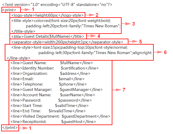
Table 26 Field description
|
No. |
Description |
|
1 |
Root node of the file. The file must contain one root node. |
|
2 |
Logo location and size. The <logo-style></logo-style>. tags appear only when a logo image has been imported to UAM. The height:6px string indicates the height of the logo is 6 pixels. As a best practice, set either the width value or the height value to adjust the logo based on the original aspect ratio. If no width or height is specified, the original logo size is used. |
|
3 |
Title format settings, including: · The color:red string indicates that the title font color is red. · The font-size:20px string indicates that the title font size is 20 pixels. · The font-weight:bold string indicates that the title text is in bold. · The padding-left:20px string indicates a left padding of 20 pixels. · The font-family:"Times New Roman" string indicates that the title font is Times New Roman. |
|
4 |
Title content. Edit the text to add additional information to the title. In this example, the title is Guest Details($fullName), where $fullName represents the guest name. |
|
5 |
Settings for the delimiter between titles and page contents. The width:260px;height:1px string indicates that the delimiter is 260 pixels wide and 1 pixel high. |
|
6 |
Page content format settings, including: · The font-size:15px string indicates that the page font size is 15 pixels. · The padding-top:10px string indicates a top padding of 100 pixels. · The font-style:normal string indicates that the page font style is normal. · The padding-left:30px string indicates a left padding of 30 pixels. · The font-family:"Times New Roman" string indicates that the page font is Times New Roman. · The align:right string indicates that the page content is right aligned. |
|
7 |
Page contents. Each line indicates a parameter name and the value. To add other parameters to the page, make sure the new strings are consistent with the field names in the user additional information. For example, to add the company name for the guest, configure <line>Company name: $Company name</line>. For more information about user additional information, see HPE Intelligent Management Center v7.3 Enterprise and Standard Platform Administrator Guide. |
|
|
NOTE: · UAM ignores contents that are not enclosed by tags. · To configure the size of the print preview page, add <window-size></window-size> tags to the root node. For example, use <window-size width="550" height="650"></window-size> to indicate a page of 650 × 550 pixels. |
5. Click Print Preview.
The Print Preview page displays the most recent guest information.
6. Click OK.
Preregistering a guest on the self-service center login page (by a guest)
This topic describes how to preregister a guest on the self-service center login page. For more information about the self-service center, see "Using the user self-service."
To allow a guest to perform preregistration, complete the following configurations:
· Specify at least one access user as a guest manager in guest management. For more information, see "Adding a guest manager."
· Specify at least one service as a guest service in guest management. For more information, see "Adding guest services."
· Customize a Self-Service Center login page that includes the Guest Preregister link. For more information, see "Customizing and applying self-service pages."
To preregister a guest:
1. Open the Web browser, and enter http://ip:port/selfservice in the address bar to open the self-service center login page.
In http://ip:port/selfservice, ip is the IP address of the server with the self-service component installed and port is the HTTP or HTTPS service port number provided by the self-service component.
2. Click the Preregister Guest link.
3. Configure the following basic information:
¡ Guest Name—Real name of the guest.
¡ Identity Number—Number of the guest's identity certificate, for example, ID card or passport.
¡ Organization—Organization of the guest.
¡ Telephone—Telephone number of the guest.
¡ Email—Email address of the guest.
4. Configure the user access information:
¡ Account Name—Account name that the guest uses to access the network. The account name must be unique in UAM.
¡ Guest Manager—Guest manager who is responsible for managing the guest's account. You can select a guest manager from the list.
¡ Password/Confirm Password—Password that the guest uses to access the network.
¡ Visited Department—Department that the guest visits.
¡ Receptionist—Name of the person who the guest visits. Generally, the receptionist is the enterprise staff corresponding to the guest manager.
¡ Max. Concurrent Logins—Maximum number of concurrent online users who can use the guest account.
¡ Verification Code—Letters and numbers that display on the image at the right.
5. Click OK.
6. Click Reset to restore all information to the default.
· When guest auto-registration is disabled, UAM displays the registration result page after a guest account is preregistered. The guest manager uses either of the following methods to approve the guest registration:
¡ Scans the QR code on the registration result page to access the page for approving registration of the guest.
The QR code is displayed only when the Display QR Code after Guest Preregistration parameter is set to Yes in the guest policy. After approval, the guest can scan the QR code to get the endpoint authenticated for network access.
¡ Logs in to the self-service center to approve the guest registration.
If Display QR Code after Guest Preregistration is set to No in the guest policy, UAM sends an approval notification message by SMS or email to the guest manager. The guest manager must log in to the self-service center to approve registration of the guest.
· When guest auto-registration is enabled, UAM automatically registers the guest account immediately after the account is preregistered. It then sends the account name and password to the guest by SMS and email. The sending result is displayed on the registration result page.
For more information about configuring guest auto-registration, see "Managing guest policies."
To use the SMS function, enable IMC to send SMS messages, and configure a telephone number or account name for the guest in the required format. To use the email function, first configure the mail server settings. For more information, see HPE Intelligent Management Center v7.3 Enterprise and Standard Platform Administrator Guide. Make sure the email address configured for the guest is valid.
Managing preregistered guests in the self-service center (by a guest manager)
This topic describes only how a guest manager manages preregistered guests in the self-service center. For more information about the self-service center, see "Using the user self-service."
Open the Web browser, and enter http://ip:port/selfservice in the address bar to open the self-service center login page. Then, input the account name, password, and verification code, select Ordinary user from the User type list, and click Login to log in to the self-service center.
In http://ip:port/selfservice, ip is the IP address of the server with the self-service component installed and port is the HTTP or HTTPS service port number provided by the self-service component.
Accessing the preregistered guest list page
To view preregistered guests, select Guest Management > All Preregistered Guests from the navigation tree.
If you are a super guest manager, the list includes all preregistered guests. If you are a guest manager, the list includes only preregistered guests who have selected the guest manager during guest preregistration.
Preregistered guest list contents
· Account Name—Account name of the preregistered guest. The preregistered guest uses this account name for authentication.
· Guest Name—Real name of the preregistered guest.
· Registration Date—Date when the guest account is preregistered.
· Expiration Time—Date and time when the preregistered guest expires and becomes invalid. By default, the expiration time is 7 days after the preregistration date.
· Visited Department—Department that the preregistered guest visits.
· Receptionist—Name of the person who the preregistered guest visits.
· Register—Click the Register icon ![]() to change the preregistered
guest into a guest.
to change the preregistered
guest into a guest.
· Delete—Click the Delete icon ![]() to delete the preregistered guest.
to delete the preregistered guest.
Performing a basic query for preregistered guests
1. Access the preregistered guest list page.
2. Click the Basic Query link on the upper right side of the Query Preregistered Guests area to use the basic query.
You can perform a basic query if you see Advanced Query on the upper right side of the Query Preregistered Guests area.
3. Specify one or more of the following query criteria:
¡ Account Name—Enter a partial or complete account name of a preregistered guest. For example, if you enter x, all account names that contain x are matched.
¡ Guest Name—Enter a partial or complete real name of a preregistered guest. For example, if you enter y, all guest names that contain y are matched.
¡ Receptionist—Enter a partial or complete name of the person who a preregistered guest visits. For example, if you enter x, all receptionist names that contain x are matched.
¡ Visited Department—Enter a partial or complete name of the department that a preregistered guest visits. For example, if you enter y, all visited department names that contain y are matched.
The query ignores empty fields.
4. Click Query. The list shows all preregistered guests that match the query criteria.
5. Click Reset to clear the query criteria. The list shows all preregistered guests in the self-service center.
Performing an advanced query for preregistered guests
1. Access the preregistered guest list page.
2. Click the Advanced Query link on the upper right side of the page.
You can perform an advanced query if you see Basic Query on the upper right side of the page.
3. Specify one or more of the following query criteria:
¡ Account Name—Enter a partial or complete account name of a preregistered guest. For example, if you enter x, all account names that contain x are matched.
¡ Guest Name—Enter a partial or complete real name of a preregistered guest. For example, if you enter y, all guest names that contain y are matched.
¡ Receptionist—Enter a partial or complete name of the person who a preregistered guest visits. For example, if you enter x, all receptionist names that contain x are matched.
¡ Visited Department—Enter a partial or complete name of the department that a preregistered guest visits. For example, if you enter y, all department names that contain y are matched.
¡ Registration Date From/To—Click the Calendar icon ![]() to enter the date
when a guest is preregistered.
The registration date is in the format of YYYY-MM-DD. In the time field that is displayed, select the registration date range.
to enter the date
when a guest is preregistered.
The registration date is in the format of YYYY-MM-DD. In the time field that is displayed, select the registration date range.
¡ Guest Manager—If you are a guest manager, this field cannot be modified. If you are a super guest manager, you can select a guest manager from the list.
The query ignores empty fields.
4. Click Query. The list shows all preregistered guests that match the query criteria.
5. Click Reset to clear the query criteria. The list shows all preregistered guests in the self-service center.
Viewing preregistered guest details
1. Access the preregistered guest list page.
2. Click the account name of the preregistered guest whose detailed information you want to view.
The account details page opens.
Basic Information area
¡ Guest Name—Name of the preregistered guest.
¡ Identity Number—Number of the preregistered guest's identity certificate, for example, ID card or passport.
¡ Organization—Organization of the preregistered guest.
¡ Telephone—Telephone number of the preregistered guest.
¡ Email—Email address of the preregistered guest.
User Access Information area
¡ Account Name—Account name that the preregistered guest uses to access the network.
¡ Registration Date—Date when the guest is preregistered.
¡ Visited Department—Department that the preregistered guest visits.
¡ Receptionist—Name of the person who the preregistered guest visits. Generally, the receptionist is the enterprise staff corresponding to the guest manager.
¡ Max. Concurrent Logins—Maximum number of concurrent online users who can use the guest account.
3. Click Back to return to the preregistered guest list page.
Guest registration prerequisites
When a guest account is successfully preregistered, UAM sends the account name and password to the guest by SMS and email.
To use the SMS function, enable IMC to send SMS messages, and configure a telephone number or account name for the guest in the required format. For information about configuring SMS system parameters, see HPE Intelligent Management Center v7.3 Enterprise and Standard Platform Administrator Guide. For information about configuring the SMS message content, see "Delivering messages."
To use the email function, first configure the mail server settings. For more information, see HPE Intelligent Management Center v7.3 Enterprise and Standard Platform Administrator Guide. Make sure the email address configured for the guest is valid.
You can either register a single preregistered guest or bulk register multiple guests.
Registering a single preregistered guest
When you register a single preregistered guest, you can configure detailed information for the preregistered guest. However, registering preregistered guests one at a time is not time efficient.
To register a preregistered guest:
1. Access the preregistered guest list page.
2. Click the Register icon ![]() for the preregistered guest you want to register.
for the preregistered guest you want to register.
The Register page opens.
3. Modify the following basic information as needed:
¡ Guest Name—Name of the guest.
¡ Identity Number—The number of the guest's identity certificate, for example, ID card or passport.
¡ Organization—Organization of the guest.
¡ Telephone—Telephone number of the guest.
¡ Email—Email address of the guest.
¡ User Group—Click
the Select User Group icon ![]() . In the Select User Group window, select the
user group to which the guest belongs, and then click OK.
. In the Select User Group window, select the
user group to which the guest belongs, and then click OK.
This field is configurable only if the guest manager does not have a managed guest group. If the guest manager has a managed guest group, this field displays the name of the managed guest group and cannot be modified.
4. Configure the user access information as needed:
¡ Account Name—Account name that the guest uses to access the network. The account name must be unique in UAM.
¡ Start Time—Date and time when the guests become valid. Leave this field empty if you want the guests to become valid immediately after being created.
¡ End Time—Date and time when the guest expires and becomes invalid.
¡ Password/Confirm Password—Set the password for the guest to access the network.
¡ Visited Department—Department that the guest visits.
¡ Receptionist—Name of the person who the guest visits. Generally, the receptionist is the enterprise staff corresponding to the guest manager.
¡ Guest Manager—If you are a super guest manager, you can select a guest manager for the preregistered guest from the list, and the selected guest manager is responsible for managing the guest accounts. If you are a guest manager, this field cannot be modified.
¡ Max. Concurrent Logins—Maximum number of concurrent online users who can use the guest account.
¡ Comments—Comments for easy maintenance of guest information.
5. In the Guest Service area, select an access service for the guest. You can select only one access service for a guest.
Guest Service List content
¡ Service Name—Name of the service.
¡ Description—Description of the service for easy maintenance.
¡ Service Suffix—Identifies the name of the domain to be used for guest authentication.
¡ Status—Whether guests can apply for the service. A guest can apply for services in Available state only.
¡ Default Security Policy—Default security policy contained in the service. This parameter is displayed only when the EAD component is deployed.
6. Configure the access device binding information.
The binding parameters in this area take effect only when they are selected in the Authentication Binding Information area of the selected service. For example, the Device IP parameter is effective to the services with the Bind Access Device IP option selected.
If a binding parameter is selected for a service but the binding parameter is not configured, the self-service center automatically acquires the binding parameter information. The self-service center uses the information of the first successful authentication of the guest as the binding information.
To pass authentication, the guest must meet all requirements of the access device bindings and terminal bindings.
¡ Device SN—Enter the sequence number of the access device to which the guest is connected.
¡ Port—Enter the port through which the guest is connected to the access device. The value is the last portion of an interface number. For example, if a guest is bound to port 3, both interface number 1/0/3 and interface number 2/0/3 match the port.
¡ Outer VLAN ID—Enter the outer VLAN ID that is contained in the guest's packets.
¡ VLAN ID/Inner VLAN ID—Enter a list of VLAN IDs or inner VLAN IDs that can be contained in the guest's packets.
¡ User SSID—Enter a list of SSIDs to which the guest can be connected.
¡ Device IP—Enter a list of IPv4 address for the access devices to be bound to the guest. Each entry on the list represents the IP address of an access device bound to the guest. If a device has multiple IP addresses, use the IP address of the corresponding access device in UAM.
¡ Device IPv6 Address—Enter a list of IPv6 address for the access devices to be bound to the guest. Each entry on the list represents the IPv6 address of an access device bound to the guest. If a device has multiple IPv6 addresses, use the IPv6 address of the corresponding access device in UAM.
7. Configure the terminal binding information.
The binding parameters in this area take effect only when they are selected in the Authentication Binding Information area of the selected service. For example, the Computer Name parameter is effective to the services with the Bind Computer Name option selected.
If a binding parameter is selected for a service but the binding parameter is not configured, the self-service center automatically acquires the binding parameter information. It uses the information of the first successful authentication of the user as the binding information.
To pass authentication, the guest must meet all requirements of the access device bindings and terminal bindings.
¡ Computer Name—Enter the name of the computer to which the guest is bound.
¡ IMSI—Enter the IMSI of the endpoint to be bound to the guest.
¡ Windows Domain—Enter the name of the domain that the guest endpoint must join or log in.
¡ Terminal IP Address—Enter a list of IPv4 addresses or IPv4 address ranges for the endpoints from which the guest can access the network. The IPv4 address ranges must be specified in the format X.X.X.X-X.X.X.X.
¡ Terminal MAC Address—Enter a list of MAC addresses for the endpoints from which the guest can access the network.
¡ Terminal IPv6 Address—Enter a list of IPv6 addresses for the endpoints from which the guest can access the network. This field is displayed only when IPv6 is enabled in the UAM system settings.
¡ IMEI—Enter the IMEI of the endpoint to be bound to the guest.
8. Click OK or OK & Print.
If you click OK, UAM registers the guest.
If you click OK & Print, UAM registers the guest and displays the guest details page. Click Print at the upper right corner to display the print preview window. The window supports custom settings, such as the page size, title, and fields. For more information, see "Customizing and printing guest information." To print guest information, click Print at the top of the print preview page.
Bulk registering preregistered guests
When you bulk register preregistered guests, you can only configure the expiration time and select the guest manager and guest service for the guests. Bulk registering preregistered guests is more time-efficient than single registration. However, you cannot configure dedicated information for each preregistered guest.
To bulk register multiple preregistered guests:
1. Access the preregistered guest list page.
2. Select the account names you want to register.
3. Click Register.
The Register page opens.
4. Configure the following access information:
¡ Guest Manager—If you are a super guest manager, you can select a guest manager from the list to manage the preregistered guests. If you are a guest manager, this field displays the account name of the current guest manager.
¡ User Group—Click
the Select User Group icon ![]() . In the Select User Group window, select the
user group to which the guest belongs, and then click OK.
. In the Select User Group window, select the
user group to which the guest belongs, and then click OK.
This field is configurable only if the guest manager does not have a managed guest group. If the guest manager has a managed guest group, this field displays the name of the managed guest group and cannot be modified.
¡ Validity Time—Enter the date and time when the guests become valid. Leave this field empty if you want the guests to become valid immediately after being created.
¡ Expiration Time—Enter the date and time when the guests expire and become invalid.
5. Select a guest service for the guests. You can select only one guest service.
The Guest Service List contains the following parameters:
¡ Service Name—Name of the service.
¡ Description—Description of the service for easy maintenance.
¡ Service Suffix—Identifies the name of the domain to be used for guest authentication.
¡ Status—Whether guests can apply for the service. A guest can apply for services in Available state only.
¡ Default Security Policy—Default security policy contained in the service. This parameter is displayed only when the EAD component is deployed.
6. Click OK.
Deleting a single preregistered guest
1. Access the preregistered guest list page.
2. Click the Delete icon ![]() for the preregistered
guest you want to delete.
for the preregistered
guest you want to delete.
A confirmation dialog box opens.
3. Click OK.
Bulk deleting preregistered guests
1. Access the preregistered guest list page.
2. Select one or more account names of the preregistered guests you want to delete.
3. Click Delete.
A confirmation dialog box opens.
4. Click OK.
Managing registered guests in the self-service center (by a guest manager)
You can manage registered guests in the self-service center. For more information about the self-service center, see "Using the user self-service."
Accessing the guest list page
To view guests, select Guest Management > All Guests from the navigation tree.
· If you are a super guest manager, the list includes all the guests.
· If you are a guest manager, the list includes only the guests who have selected the guest manager when the guests are registered or added.
Guest list contents
· Account Name—Account name of the guest. The guest uses this account name for authentication.
· Guest Name—Real name of the guest.
· Validity Time—Date and time when the guest becomes valid. Leave this field empty if you want the guest to become valid immediately after being created.
· Expiration Time—Date and time when the guest expires and becomes invalid.
· Guest Group—User group to which the guest belongs.
· Modify Password—Click the Modify Password
icon ![]() to modify the password of the guest.
to modify the password of the guest.
· Modify Information—Click the Modify icon ![]() to modify the guest information.
to modify the guest information.
· Change Service—Click the Change Service icon ![]() to modify the service of the guest.
to modify the service of the guest.
· Send Password SMS Message Notifications—Click the Send Password SMS Message
Notifications icon ![]() to send an SMS message to the guest. For information about requirements for sending SMS messages, see HPE Intelligent Management Center v7.3
Enterprise and Standard Platform Administrator Guide.
to send an SMS message to the guest. For information about requirements for sending SMS messages, see HPE Intelligent Management Center v7.3
Enterprise and Standard Platform Administrator Guide.
· Send Password Email Message Notifications—Click the Send Password Email Message
Notifications icon ![]() to send an email to the guest. To use this function, configure the email server first and make
sure the correct email address is configured in the guest's basic information. For
more information about configuring the email server, see HPE Intelligent Management Center v7.3
Enterprise and Standard Platform Administrator Guide.
to send an email to the guest. To use this function, configure the email server first and make
sure the correct email address is configured in the guest's basic information. For
more information about configuring the email server, see HPE Intelligent Management Center v7.3
Enterprise and Standard Platform Administrator Guide.
Performing a basic query for guests
1. Access the guest list page.
2. Click the Basic Query link on the upper right side of the Query Guests area to use the basic query.
You can perform a basic query if you see Advanced Query on the upper right side of the Query Guests area.
3. Specify one or more of the following query criteria:
¡ Account Name—Enter a partial or complete account name of the guest. For example, if you enter x, all account names that contain x are matched.
¡ Guest Name—Enter a partial or complete real name of the guest. For example, if you enter y, all guest names that contain y are matched.
¡ Guest Service—Select a guest service from the list.
The query ignores empty fields.
4. Click Query. The list shows all guests that match the query criterion.
5. Click Reset to clear the query criteria. The list shows all guests in the self-service center.
Performing an advanced query for guests
1. Access the guest list page.
2. Click the Advanced Query link on the upper right side of the page.
You can perform an advanced query if you see Basic Query on the upper right side of the page.
3. Specify one or more of the following query criteria:
¡ Account Name—Enter a partial or complete account name of the guest. For example, if you enter x, all account names that contain x are matched.
¡ Guest Name—Enter a partial or complete real name of the guest. For example, if you enter y, all guest names that contain y are matched.
¡ Guest Manager—If you are a guest manager, this field cannot be modified. If you are a super guest manager, you can select a guest manager from the list.
¡ Guest Service—Select a guest service from the list.
¡ Visited Department—Enter a partial or complete name of the department that the guest visits. For example, if you enter y, all department names that contain y are matched.
¡ Receptionist—Enter a partial or complete name of the person who the guest visits. For example, if you enter x, all receptionist names that contain x are matched.
¡ Expiration From/To—Click the Calendar icon ![]() to select the date and time range when the account becomes invalid, or enter the date and time range in YYYY-MM-DD hh:mm format.
to select the date and time range when the account becomes invalid, or enter the date and time range in YYYY-MM-DD hh:mm format.
¡ Creation Date From/To—Click the Calendar icon ![]() to select the date
and time range when the account
was created, or enter the date and time range in YYYY-MM-DD hh:mm format.
to select the date
and time range when the account
was created, or enter the date and time range in YYYY-MM-DD hh:mm format.
The query ignores empty fields.
4. Click Query. The list shows all guests that match the query criterion.
5. Click Reset to clear the query criteria. The list shows all guests in the self-service center.
Viewing guest details
1. Access the guest list page.
2. Click the account name of the guest whose detailed information you want to view.
The account details page opens.
Basic Information area
¡ Guest Name—Name of the guest.
¡ Identity Number—Number of the guest's identity certificate, for example, ID card or passport.
¡ Organization—Organization of the guest.
¡ Telephone—Telephone number of the guest.
¡ Email—Email address of the guest.
¡ Guest Group—User group to which the guest belongs.
¡ Manager—Guest manager of the guest. This field is displayed only when the current account is a super guest manager.
User Access Information area
¡ Account Name—Account name that the guest uses to access the network.
¡ Guest Password Expiration Time—Date and time when the guest password expires. An empty field indicates the guest password never expires.
¡ Start Time—Date and time when the guest becomes valid. An empty field indicates that the guest becomes valid immediately after being created.
¡ End Time—Date and time when the guest expires and becomes invalid.
¡ Visited Department—Name of the department that the guest visits.
¡ Receptionist—Name of the person who the guest visits. Generally, the receptionist is the enterprise staff corresponding to the guest manager.
¡ Max. Concurrent Logins—Maximum number of concurrent online users who can use the guest account.
Apply Guest Service area
This area displays the guest service that the guest uses. A guest can apply for only one service.
¡ Service Name—Name of the service.
¡ Description—Description of the service for easy maintenance.
¡ Service Suffix—Identifies the name of the domain to be used for guest authentication.
¡ Default Security Policy—Default security policy contained in the service. This parameter is displayed only when the EAD component is deployed.
Access Device Binding Information area
To pass authentication, the guest must meet all requirements of the access device bindings and terminal bindings. The query ignores empty fields.
¡ Device SN—Requires the guest connect to the access device that has the specified sequence number.
¡ Port—Requires the guest be connected through the specified port of the access device. The value is the last portion of an interface number. For example, if a guest is bound to port 3, both interface number 1/0/3 and interface number 2/0/3 match the port.
¡ Outer VLAN ID—Requires the guest's packets carry the specified outer VLAN ID.
¡ VLAN ID/Inner VLAN ID—Requires the guest's packets carry any of the specified VLAN IDs or inner VLAN IDs.
¡ User SSID—Requires the guest connect to the network that uses any of the specified SSIDs.
¡ Device IP—Requires the guest connect to the access device that uses any of the specified IPv4 addresses. Each entry on the list represents the IPv4 address of an access device bound to the guest. If a device has multiple IP addresses, use the IPv4 address of the corresponding access device in UAM.
¡ Device IPv6 Address—Requires the guest connect to the access device that uses any of the specified IPv6 addresses. Each entry on the list represents the IPv6 address of an access device bound to the guest. If a device has multiple IPv6 addresses, use the IPv6 address of the corresponding access device in UAM. This field is displayed only when IPv6 is enabled in the UAM system settings.
Terminal Binding Information area
To pass authentication, the guest must meet all requirements of the access device bindings and terminal bindings. The query ignores empty fields.
¡ Computer Name—Requires the guest connect from the specified computer.
¡ IMSI—Requires the guest endpoint to use the specified IMSI.
¡ Windows Domain—Requires the guest endpoint to join or log in to specified domain.
¡ Terminal IP Address—Requires the guest endpoint to use any of the specified IPv4 addresses or an IP address in the specified IPv4 address ranges. IP address ranges are specified in the format X.X.X.X-X.X.X.X.
¡ Terminal MAC Address—Requires the guest endpoint to use any of the specified MAC addresses.
¡ Terminal IPv6 Address—Requires the guest endpoint to use any of the specified IPv6 addresses. This field is displayed only when IPv6 is enabled in the UAM system settings.
¡ IMEI—Requires the guest endpoint to use the specified IMEI.
Print link
Click Print at the upper right corner to display the print preview window. The window supports custom settings, such as the page size, title, and fields. For more information, see "Customizing and printing guest information."
To print guest information, click Print at the top of the print preview page.
3. Click Back to return to the guest list page.
Adding a guest
A guest manager can add guests in the self-service center. A guest added in this way can perform authentication directly and can access the network without being registered.
To add a guest:
1. Access the guest list page.
2. Click Add.
3. Configure the following basic information:
¡ Guest Name—Enter the name of the guest.
¡ Identity Number—Enter the number of the guest's identity certificate, for example, ID card or passport.
¡ Organization—Enter the organization of the guest.
¡ Telephone—Enter the telephone number of the guest.
¡ Email—Enter the email address of the guest.
¡ User Group—Click
the Select User Group icon ![]() . In the Select User Group window, select the
user group to which the guest belongs, and then click OK.
. In the Select User Group window, select the
user group to which the guest belongs, and then click OK.
This field is configurable only if the guest manager does not have a managed guest group. If the guest manager has a managed guest group, this field displays the name of the managed guest group and cannot be modified.
¡ Guest Manager—If you are a super guest manager, you can select a guest manager to manage the preregistered guest from the list. If you are a guest manager, this field does not appear.
4. Configure the user access information:
¡ Account Name—Enter the unique account name that the guest uses to access the network.
¡ Auto Generate Password—Select this option to enable UAM to automatically generate and send a password to the guest by email. When this option is selected, the Password and Confirm Password fields are hidden.
¡ Start Time—Enter the date and time when the guest becomes valid. Leave this field empty if you want the guest to become valid immediately after being created.
¡ End Time—Enter the date and time when the guest expires and becomes invalid.
¡ Password/Confirm Password—Set the password that the guest uses to access the network.
¡ Visited Department—Enter the name of the department that the guest visits.
¡ Receptionist—Enter the name of the person who the guest visits. Generally, the receptionist is the enterprise staff corresponding to the guest manager.
¡ Max. Concurrent Logins—Enter the maximum number of concurrent online users who can use the guest account.
5. Apply for a service for the guest. A guest can apply for only one service.
The Guest Service List contains the following parameters:
¡ Service Name—Name of the service.
¡ Description—Description of the service for easy maintenance.
¡ Service Suffix—Identifies the name of the domain to be used for guest authentication.
¡ Status—Whether guests can apply for the service. A guest can apply for services in Available state only.
¡ Default Security Policy—Default security policy contained in the service. This parameter is displayed only when the EAD component is deployed.
6. Configure the access device binding information.
The binding parameters in this area take effect only when they are selected in the Authentication Binding Information area of the selected service. For example, the Device IP parameter is effective to the services with the Bind Access Device IP option selected.
If a binding parameter is selected for a service but the binding parameter is not configured, the self-service center automatically acquires the binding parameter information from the first successful authentication of the guest.
To pass authentication, the guest must meet all requirements of the access device bindings and terminal bindings.
¡ Device SN—Enter the sequence number of the access device to which the guest is connected.
¡ Port—Enter the port through which the guest is connected to the access device. The value is the last portion of an interface number. For example, if a guest is bound to port 3, both interface number 1/0/3 and interface number 2/0/3 match the port.
¡ Outer VLAN ID—Enter the outer VLAN ID that is contained in the guest's packets.
¡ VLAN ID/Inner VLAN ID—Enter a list of VLAN IDs or inner VLAN IDs that can be contained in the guest's packets.
¡ User SSID—Enter a list of SSIDs to which the guest can be connected.
¡ Device IP—Enter a list of IPv4 address for the access devices to be bound to the guest. Each entry on the list represents the IP address of an access device bound to the guest. If a device has multiple IP addresses, use the IP address of the corresponding access device in UAM.
¡ Device IPv6 Address—Enter a list of IPv6 address for the access devices to be bound to the guest. Each entry on the list represents the IPv6 address of an access device bound to the guest. If a device has multiple IPv6 addresses, use the IPv6 address of the corresponding access device in UAM.
7. Configure terminal binding information.
The binding parameters in this area take effect only when they are selected in the Authentication Binding Information area of the selected service. For example, the Computer Name parameter is effective to the services with the Bind Computer Name option selected.
If a binding parameter is selected for a service but the binding parameter is not configured, the self-service center automatically acquires the binding parameter information from the first successful authentication of the user.
To pass authentication, the guest must meet all requirements of the access device bindings and terminal bindings.
¡ Computer Name—Enter the name of the computer to which the guest is bound.
¡ IMSI—Enter the IMSI of the endpoint to be bound to the guest.
¡ Windows Domain—Enter the name of the domain that the guest endpoint must join or log in.
¡ Terminal IP Address—Enter a list of IPv4 addresses or IPv4 address ranges for the endpoints from which the guest can access the network. The IPv4 address ranges must be specified in the format X.X.X.X-X.X.X.X.
¡ Terminal MAC Address—Enter a list of MAC addresses for the endpoints from which the guest can access the network.
¡ Terminal IPv6 Address—Enter a list of IPv6 addresses for the endpoints from which the guest can access the network. This field is displayed only when IPv6 is enabled in the UAM system settings.
¡ IMEI—Enter the IMEI of the endpoint to be bound to the guest.
8. Click OK or OK & Print.
¡ If you click OK, UAM adds the guest.
¡ If you click OK & Print, UAM adds the guest and displays the guest details page.
¡ On the guest details page, click Print at the upper right corner to display the print preview window. The window supports custom settings, such as the page size, title, and fields. For more information, see "Customizing and printing guest information." To print guest information, click Print at the top of the print preview page.
Batch generating guests
A guest manager can generate guests in batches in the Self-Service Center. The generated guests can directly trigger authentication for network access without experiencing a separate registration process. To inform guests of the accounts and passwords, configure a phone number or email address for each guest, or print guest information for distribution.
To generate guests in batches:
1. Access the guest list page.
2. Click Batch Generate.
3. Configure the user access information:
¡ Guest Number—Enter the number of guests to be generated.
¡ Account Name Prefix—Enter a string of 4 to 8 characters as the account name prefix. The prefix cannot include Tab or any of the following characters:
# + / ? % & = * @ \ " [ ] ( ) < > '
¡ User Group—Click the Select User Group icon ![]() , select a group, and click OK.
, select a group, and click OK.
¡ Max. Concurrent Logins—Enter the maximum number of online users who can use the guest account at the same time.
¡ Validity Time—Enter the date and time when the guests become valid. Leave this field empty if you want the guests to become valid immediately after being created.
¡ Expiration Time—Enter the date and time when the guests expire and become invalid.
¡ Visited Department—Enter the name of the department that the guests visit.
¡ Receptionist—Enter the name of the receptionist for the guests. Typically, the receptionist is the guest manager of the guests.
¡ Comments—Enter comments for the guests to be generated in batches for easy maintenance.
4. Apply for a service for the guests. A guest can apply for only one service.
The Guest Service List contains the following parameters:
¡ Service Name—Name of the service.
¡ Description—Description of the service for easy maintenance.
¡ Service Suffix—Identifies the name of the domain to be used for identity authentication of guests.
¡ Status—Whether guests can apply for the service. A guest can apply for services in Available state only.
¡ Default Security Policy—Default security policy contained in the service. This parameter is displayed only when the EAD component is deployed.
5. Click OK.
UAM starts to generate the guest accounts. Each guest account contains the specified prefix and an 8-character suffix that is randomly generated by UAM.
The operation result page displays the number of successfully generated guests and the number of failures. If failures occur, click Download to check the failure reason.
Importing guests in batches
You can manage registered guests in the self-service center. For more information about the self-service center, see "Using the user self-service."
Open the Web browser, and enter http://ip:port/selfservice in the address bar to open the self-service center login page. Then, input the account name, password, and verification code, select Ordinary user from the User type list, and click Login to log in to the self-service center.
In http://ip:port/selfservice, ip is the IP address of the server with the self-service component installed and port is the HTTP or HTTPS service port number provided by the self-service component.
To import accounts in batches:
1. From the navigation tree, select Guest Management > All Guests.
2. Click Batch Import.
3. For the Import File box, click Browse to select the text file that saves the account information.
UAM supports importing only text files in ANSI format.
4. Select the column separator from the list. Options are Space, TAB, comma (,), colon (:), pound sign (#), and dollar sign ($).
5. Select whether to send an SMS message to guests.
If Send Password by SMS is selected, UAM sends an SMS message to notify imported guests of the account name and password. To use the SMS function, enable IMC to send SMS messages and make sure the import file contains a telephone number or account name for each guest in the required format. For information about configuring SMS system parameters, see HPE Intelligent Management Center v7.3 Enterprise and Standard Platform Administrator Guide. For information about configuring the SMS message content, see "Delivering messages."
6. Select whether to send an email to guests.
If Send Password by Email is selected, UAM sends an email to notify imported users of the account name and password. To use the email function, first configure the mail server settings. For more information, see HPE Intelligent Management Center v7.3 Enterprise and Standard Platform Administrator Guide. Make sure the email address configured for each guest is valid.
7. Click Next to display the batch import page.
UAM automatically analyzes the number of columns available in the text file, and display the result in the list of each parameter.
Make sure the parameters in the text file comply with the specified format and value range. For example, an account name can contain only spaces, case-sensitive letters, numbers, hyphens (-), underscores (_), and dots (.). Any account name that contains other characters results in an import failure.
Basic Information
¡ Guest Name—Name of the guests. This parameter must be read from the imported file. Select the specified column number in the file as the guest name.
¡ Identity Number—Identity number of the guests. This parameter must be read from the imported file. Select the specified column number in the file as the identity number.
¡ Contact Address—Contact address of the guests. This parameter can be either read from the imported file or manually specified. You can select the specified column number in the file as the contact address, or select Not Imported and enter a contact address. The contact address you entered applies to all imported guests.
¡ Telephone—Telephone number of the guests. This parameter can be either read from the imported file or manually specified. You can select the specified column number in the file as the telephone number, or select Not Imported and enter a telephone number. The telephone number you entered applies to all imported guests.
¡ Email—Email address of the guests. This parameter can be either read from the imported file or manually specified. You can select the specified column number in the file as the email address, or select Not Imported and enter an email address. The email address you entered applies to all imported guests.
¡ User Group—User
group to which the guests belong. This parameter must be manually configured.
Click the Select User Group icon ![]() . In the Select User Group window, select the
user group for the guests, and then click OK.
. In the Select User Group window, select the
user group for the guests, and then click OK.
User Access Information
¡ Account Name—Account name of the guests. This parameter must be read from the imported file. Select the specified column number in the file as the account name.
¡ Validity Time—Date and time when the guests
become valid. This parameter can be either imported from the file or manually specified. To import the time, select a column number in the file. To manually
specify the time, select Not Imported,
and then enter a time string in YYYY-MM-DD hh:mm format or click the Calendar icon ![]() to set the time. Manually
specified time applies to all imported guests. If this field is empty, guests become valid immediately after being
imported.
to set the time. Manually
specified time applies to all imported guests. If this field is empty, guests become valid immediately after being
imported.
¡ Expiration Time—Date and time when the
guests expire and become invalid. This parameter can be either imported from
the file or manually specified. To import the time, select a column number in the file. To manually
specify the time, select Not Imported,
and then enter a time string in YYYY-MM-DD hh:mm format or click the Calendar icon ![]() to set the time. Manually
specified time applies to all imported guests. If this
field is empty, imported guests never expire.
to set the time. Manually
specified time applies to all imported guests. If this
field is empty, imported guests never expire.
¡ Password—Password of the guests. This parameter can be either read from the imported file or manually specified. You can select the specified column number in the file as the password, or select Not Imported and enter a password. The password you enter applies to all imported guests.
¡ Receptionist—Name of the person who the guest visits. This parameter can be either read from the imported file or manually specified. You can select the specified column number in the file as the receptionist, or select Not Imported and enter a receptionist. The password you enter applies to all receptionists.
¡ Visited Department—Name of the department that the guest visits. This parameter can be either read from the imported file or manually specified. You can select the specified column number in the file as the visited department, or select Not Imported and enter a visited department. The password you enter applies to all visited departments.
¡ Max. Concurrent Logins—Maximum number of concurrent online users who can use the same guest account. You can select a column number, or select Not Imported and enter a value. The value you enter applies to all imported guests.
Guest Access Service
Access services can only be selected from the access service list. You can select multiple services with different suffixes. The access services you specify apply to all imported access guests.
¡ Service Name—Name of the service.
¡ Description—Description of the service for easy maintenance.
¡ Service Suffix—Identifies the name of the domain to be used for guest authentication.
¡ Status—Whether guests can apply for the service. A guest can apply for services in Available state only.
Access Device Binding Information
The binding parameters in this area take effect only when they are selected in the Authentication Binding Information area of the selected services. For example, the Device IP parameter is effective to the services with the Bind Access Device IP option selected.
To pass authentication, the guests must meet all requirements of the access device bindings and terminal bindings.
¡ Device IP—IP address of the access device bound to the guests. To pass authentication, a guest must connect to the access device that uses this IP address. If an access device has multiple IP addresses, the one that the access device used when it was added to UAM is adopted as the device IP. This parameter can be either read from the imported file or manually specified. You can select the specified column number in the file as the device IP, or select Not Imported and enter a device IP. The device IP you enter applies to all imported guests. If this field is empty, the binding parameter is automatically learned and the parameter used for the first successful authentication is adopted.
¡ Device IPv6 Address—IPv6 address of the access device bound to the guests. To pass authentication, a guest must connect to the access device that uses this IPv6 address. If an access device has multiple IPv6 addresses, the one that the access device used when it was added to UAM is adopted as the device IPv6 address. This parameter can be either read from the imported file or manually specified. You can select the specified column number in the file as the device IPv6 address, or select Not Imported and enter a device IPv6 address. The device IPv6 address you enter applies to all imported guests. If this field is empty, the binding parameter is automatically learned and the parameter used for the first successful authentication is adopted. This field is displayed only when IPv6 is enabled in the UAM system settings.
¡ Port—Port to which the guests are bound. To pass authentication, a guest must connect to the specified port on a device. In UAM, each guest is bound to only the last portion of an interface number. For example, if a guest is bound to port 3, both interface number 1/0/3 and interface number 2/0/3 match the port. This parameter can be either read from the imported file or manually specified. You can select the specified column number in the file as the port number, or select Not Imported and enter a port number. If this field is empty, the binding parameter is automatically learned and the parameter used for the first successful authentication is adopted. The port number you enter applies to all imported guests.
¡ Device SN—Sequence number of the access device bound to each guest. Select the column that contains the device sequence number in the file, or select Not Import from File and then manually set the same sequence number for all guests to be imported or keep the field empty. If this field is empty, the binding parameter is automatically learned and the parameter used for the first successful authentication is adopted.
¡ VLAN ID/Inner VLAN ID—VLAN ID or inner VLAN ID bound to the guests. This parameter can be either read from the imported file or manually specified. You can select the specified column number in the file as the VLAN ID/inner VLAN ID, or select Not Imported and enter a VLAN ID/inner VLAN ID. The VLAN ID/inner VLAN ID you enter applies to all imported guests. If this field is empty, the binding parameter is automatically learned and the parameter used for the first successful authentication is adopted.
¡ Outer VLAN ID—Outer VLAN ID bound to the guests. This parameter can be either read from the imported file or manually specified. You can select the specified column number in the file as the outer VLAN ID, or select Not Imported and enter an outer VLAN ID. The outer VLAN ID you enter applies to all imported guests. If this field is empty, the binding parameter is automatically learned and the parameter used for the first successful authentication is adopted.
¡ User SSID—SSID used by the guests for wireless access. To pass authentication, a guest must use the specified SSID. This parameter can be either read from the imported file or manually specified. You can select the specified column number in the file as the SSID, or select Not Imported and enter an SSID. The SSID you enter applies to all imported guests. If this field is empty, the binding parameter is automatically learned and the parameter used for the first successful authentication is adopted.
Terminal Binding Information
The binding parameters in this area take effect only when they are selected in the Authentication Binding Information area of the selected services. For example, the Computer Name parameter is effective to the services with the Bind Computer Name option selected.
To pass authentication, the guests must meet all requirements of the access device bindings and terminal bindings.
¡ Computer Name—Computer name bound to guests. To pass authentication, a guest must access from the specified computer. This parameter must be read from the imported file, because guests are not bound to the same computer name. Select the specified column number in the file as the computer name. If this field is empty, the binding parameter is automatically learned and the parameter used for the first successful authentication is adopted.
¡ Bound Domain—Domain name bound to the guests. To pass authentication, a guest must join or log in to the specified domain. This parameter does not require the computer to log on to the domain. This parameter can be either read from the imported file or manually specified. You can select the specified column number in the file as the domain name, or select Not Imported and enter a domain name. The domain name you enter applies to all imported guests. If this field is empty, the binding parameter is automatically learned and the parameter used for the first successful authentication is adopted.
¡ Terminal IP Address—List of IPv4 addresses or IPv4 address ranges bound to the guests. To pass authentication, a guest must access from the computer that uses a bound IPv4 address or an IPv4 address in the bound IPv4 address ranges. This parameter must be read from the imported file, because guests are not bound to the same IPv4 address. Select the specified column number in the file as the bound IPv4 addresses or IPv4 address ranges. If this field is empty, the binding parameter is automatically learned and the parameter used for the first successful authentication is adopted.
¡ Terminal IPv6 Address—List of IPv6 addresses bound to the guests. To pass authentication, a guest must access from the computer that uses an IPv6 address on the list. This parameter must be read from the imported file, because guests are not bound to the same IPv6 address. Select the specified column number in the file as the bound IPv6 addresses. If this field is empty, the binding parameter is automatically learned and the parameter used for the first successful authentication is adopted.
¡ Terminal MAC Address—List of MAC addresses bound to the guests. To pass authentication, a guest must access from the computer that uses a MAC address on the list. This parameter must be read from the imported file, because guests are not bound to the same MAC address. Select the specified column number in the file as the bound MAC addresses. If this field is empty, the binding parameter is automatically learned and the parameter used for the first successful authentication is adopted.
¡ IMSI—IMSI bound to the guests. To pass authentication, a guest endpoint must use the specified IMSI. This parameter must be read from the imported file, because guests are not bound to the same IMSI. Select the specified column number in the file as the IMSI. If this field is empty, the binding parameter is automatically learned and the parameter used for the first successful authentication is adopted.
¡ IMEI—IMEI bound to the guests. To pass authentication, a guest endpoint must use the specified IMEI. This parameter must be read from the imported file because guests are not bound to the same IMEI. Select the specified column number in the file as the IMEI. If this field is empty, the binding parameter is automatically learned and the parameter used for the first successful authentication is adopted.
8. Click Preview to launch the Preview Import Result window, showing the first ten imported entries. Check whether the import result is as expected.
9. Click Cancel to return to the import page.
10. Click OK to start importing the accounts in batches.
After the import is completed, the operation result page opens, showing the number of import successes and failures. If import failures occur, click Download to check the failure reason.
The Operation Failure Logs list provides the last 20 import logs.
11. Click the link in the Operation Result column to view the operation result.
Modifying the password of a single guest
1. Access the guest list page.
2. Click Modify Password for the guest for which you want to modify the password.
The Modify Password page opens.
3. Enter the password in the Password and Confirm Password fields.
4. Click OK.
Modifying detailed information about a single guest
1. Access the guest list page.
2. Click the Modify icon ![]() for the guest for
which you want to modify the detailed information.
for the guest for
which you want to modify the detailed information.
3. Modify parameters for the guest. The guest name, identity number, guest group, and account name cannot be modified. For more information, see "Adding a guest."
4. Click OK.
Changing the service for a guest
1. Access the guest list page.
2. Click the Change Service icon ![]() for the guest for which you want to change the service.
for the guest for which you want to change the service.
3. Change the service for the guest.
A guest can apply for only one service. The Guest Service List contains the following parameters:
¡ Service Name—Name of the service.
¡ Description—Description of the service for easy maintenance.
¡ Service Suffix—Identifies the name of the domain to be used for guest authentication.
¡ Status—Whether guests can apply for the service. A guest can apply for services in Available state only.
¡ Default Security Policy—Default security policy contained in the service. This parameter is displayed only when the EAD component is deployed.
4. Click OK.
Sending SMS messages to a single guest
1. Access the guest list page.
2. Click Send SMS for the guest to which you want to send an SMS message.
3. In the window that opens, enter a message and click OK.
For information about configuring SMS system parameters, see HPE Intelligent Management Center v7.3 Enterprise and Standard Platform Administrator Guide. For information about configuring the SMS message content, see "Delivering messages."
Scheduling SMS messages for guests
1. Access the guest list page.
2. Select one or more guest names.
3. Click Set Message Time.
4. Select Schedule Send.
5. Click the Calendar icon ![]() next to Message Sending Time to select the date and time, or enter the date and time in YYYY-MM-DD hh:00 format.
next to Message Sending Time to select the date and time, or enter the date and time in YYYY-MM-DD hh:00 format.
6. Click OK.
For information about configuring SMS system parameters, see HPE Intelligent Management Center v7.3 Enterprise and Standard Platform Administrator Guide. For information about configuring the SMS message content, see "Delivering messages."
Bulk modifying the expiration time for guests
This task is available only when the guest manager is not configured with the parameter Guest Maximum Validity Time. If the parameter is configured, the Set Expiration button does not appear on the guest list page in the self-service center.
To bulk modify the expiration time for guests:
1. Access the guest list page.
2. Select one or more guests for which you want to modify the expiration time.
3. Click Set Expiration.
The Set Expiration page opens.
4. Click the Calendar icon ![]() to select the expiration time, or enter the expiration time in YYYY-MM-DD hh:mm format.
to select the expiration time, or enter the expiration time in YYYY-MM-DD hh:mm format.
The expiration time must be later than the current time.
5. Click OK.
Bulk changing the guest manager for guests
Only a super guest manager can change the guest manager for guests. If you are a guest manager, the Set Manager button does not appear.
To bulk change the guest manager for guests:
1. Access the guest list page.
2. Select one or more guests for which you want to modify the guest manager.
3. Click Set Manager.
The Set Manager page opens.
4. Select a guest manager from the list.
5. Click OK.
Bulk resetting the passwords for guests
1. Access the guest list page.
2. Select one or more guests for which you want to change the passwords.
3. Click Reset Password.
UAM automatically sends the new passwords to the email of the selected guests.
Printing single guest information
Click Print or OK & Print on the page when you view, add, or register a guest. For more information, see "Viewing guest details," "Adding a guest," and "Registering a single preregistered guest."
Bulk printing guest information
You can bulk print information for up to 50 guests at a time.
To bulk print guest information:
1. Access the guest list page.
2. Select one or more guests for which you want to print information.
3. Click Print.
A print preview window opens.
4. Click Print.
The print preview window supports custom settings, such as the page size, title, and fields. For more information, see "Customizing and printing guest information."
Deleting guests
1. Access the guest list page.
2. Select one or more guests you want to delete.
3. Click Delete.
A confirmation dialog box opens.
4. Click OK.
Preregistering a guest on the Guest Center login page
The Guest Center login page provides a link for account preregistration.
To enable guest preregistration, complete the following tasks:
· Specify at least one access user as a guest manager in guest management. For more information, see "Adding a guest manager."
· Specify at least one service as a guest service in guest management. For more information, see "Adding guest services."
· Custom a self-service login page that includes the Guest Preregister link. For more information, see "Customizing and applying self-service pages."
To preregister a guest:
1. In the Web browser, enter http://ip:port/guest in the address bar to open the Guest Center login page.
In http://ip:port/guest, ip is the IP address of the server with the User Selfservice Management component installed and port is the HTTP service port number provided by the User Selfservice Management component.
2. Click the Preregister Guest link.
3. Configure the following basic information:
¡ Guest Name—Real name of the guest.
¡ Identity Number—Number of the guest's identity certificate, for example, ID card or passport.
¡ Organization—Organization of the guest.
¡ Telephone—Telephone number of the guest.
¡ Email—Email address of the guest.
4. Configure the user access information:
¡ Account Name—Account name that the guest uses to access the network. The account name must be unique in UAM.
¡ Guest Manager—Guest manager who is responsible for managing the guest's account. Select a guest manager from the list.
¡ Password/Confirm Password—Password of the guest for network access.
¡ Visited Department—Department that the guest visits.
¡ Receptionist—Name of the receptionist for the guest. Typically, the receptionist is the guest manager.
¡ Max. Concurrent Logins—Maximum number of online users who can use the guest account at the same time.
¡ Verification Code—Letters and numbers that appear in the image next to the field.
5. Click OK.
6. Click Reset to restore all information to the default.
The approval process for a preregistered guest varies depending on whether or not guest auto-registration is enabled.
· When guest auto-registration is disabled, UAM displays the registration results page after a guest account is preregistered. The guest manager uses either of the following methods to approve the guest registration:
¡ Scans the QR code on the registration results page to access the page for approving the registration of the guest.
The QR code is displayed only when the Display QR Code after Guest Preregistration parameter is set to Yes in the guest policy. After approval, the guest can scan the QR code to get the endpoint authenticated for network access.
¡ Logs in to the self-service center to approve the guest registration.
If Display QR Code after Guest Preregistration is set to No in the guest policy, UAM sends an approval notification message by SMS or email to the guest manager. The guest manager must log in to the self-service center to approve the registration of the guest.
· When guest auto-registration is enabled, UAM automatically registers the guest account immediately after the account is preregistered. It then sends the account name and password to the guest by SMS and email. The sending result is displayed on the registration results page.
For more information about configuring guest auto-registration, see "Managing guest policies."
To use the SMS function, enable IMC to send SMS messages, and configure a telephone number or account name for the guest in the required format. For information about configuring SMS system parameters, see HPE Intelligent Management Center v7.3 Enterprise and Standard Platform Administrator Guide. For information about configuring the SMS message content, see "Delivering messages."
To use the email function, configure the mail server settings and make sure the email address configured for the guest is valid. For more information, see HPE Intelligent Management Center v7.3 Enterprise and Standard Platform Administrator Guide.
Managing preregistered guests in the Guest Center
Guest managers can manage preregistered guests in the Guest Center.
In the Web browser, enter http://ip:port/guest in the address bar to open the self-service center login page. Then, enter the account name, password, and verification code, and click Login to log in to the Guest Center.
In http://ip:port/guest, ip is the IP address of the server with the self-service component installed and port is the HTTP service port number provided by the self-service component.
After logging in to the Guest Center, a guest manager can view information about preregistered guests, or query, register, and delete preregistered guests. Preregistered guest management in the Guest Center is similar to that in the Self-Service Center. For more information, see "Managing preregistered guests in the self-service center (by a guest manager)."
Managing registered guests in the Guest Center
In the Guest Center, a guest manager can perform the following tasks to manage the registered guests:
· View the registered guest list and key information about registered guests.
· Perform a basic or an advanced query of registered guests.
· View the registered guest details.
· Add guests, who can directly trigger authentication for network access without experiencing a separate registration process.
· Import guests in batches. The imported guests can directly trigger authentication for network access without experiencing a separate registration process.
· Modify the password for a guest.
· Modify detailed information about a guest.
· Change the service used by a guest.
· Send SMS messages to a guest.
· Schedule delivery of SMS messages to guests.
· Bulk modify the expiration time for guests.
· Bulk change the guest manager for guests.
· Bulk reset the passwords for guests.
· Print guest information.
· Delete guests.
Registered guest management in the Guest Center is similar to that in the Self-Service Center. For more information, see "Managing registered guests in the self-service center (by a guest manager)."
IMC administrator managing guests in UAM
The IMC administrator can manage the guests in UAM. UAM displays all guests who have been registered from preregistered guests by the guest managers and the guests who are added by guest managers.
Accessing the guest list page
1. Click the User tab.
2. From the navigation tree, select Guest > All Guests.
The list includes all guests.
Guest list contents
¡ Account Name—Account name of the guest. The guest uses this account name for authentication.
¡ Guest Name—Real name of the guest.
¡ Organization—Organization to which the guest belongs.
¡ Expiration Time—Date and time when the guest expires and becomes invalid.
¡ Guest Group—User group to which the guest belongs.
¡ Manager—Guest manager of the guest. Click the name to view the access user information for the guest manager. This field does not display super guest managers.
¡ Guest Manager Group—User group to which the guest manager belongs.
¡ Creation Date—Date when the guest was registered.
Performing a basic query for guests
1. Access the guest list page.
2. Click the Basic Query link on the upper right side of the Query Guests area to use the basic query.
You can perform a basic query if you see Advanced Query on the upper right side of the Query Guests area.
3. Specify one or more of the following query criteria:
¡ Account Name—Enter a partial or complete account name of a guest. For example, if you enter x, all account names that contain x are matched.
¡ Guest Name—Enter a partial or complete real name of a guest. For example, if you enter y, all guest names that contain y are matched.
¡ Guest Group—Click
the Select User Group icon ![]() to select a group in the Select User Group
window.
to select a group in the Select User Group
window.
¡ Guest Service—Select a guest service from the list.
The query ignores empty fields.
4. Click Query. The list includes all guests that match the query criteria.
5. Click Reset to clear the query criteria. The list includes all guests in UAM.
Performing an advanced query for guests
1. Access the guest list page.
2. Click the Advanced Query link on the upper right side of the page.
You can perform an advanced query if you see Basic Query on the upper right side of the page.
3. Specify one or more of the following query criteria:
¡ Account Name—Enter a partial or complete account name of a guest. For example, if you enter x, all account names that contain x are matched.
¡ Guest Name—Enter a partial or complete real name of a guest. For example, if you enter y, all guest names that contain y are matched.
¡ Guest Group—Click
the Select User Group icon ![]() to select a group in the Select User Group
window.
to select a group in the Select User Group
window.
¡ Guest Service—Select a guest service from the list.
¡ Status—Select an account state from the list. Options include Normal and Cancelled. The normal state indicates that the guest can be normally used. The cancelled state indicates that the guest has been cancelled.
¡ Manager—Enter a partial or complete manager of a guest. For example, if you enter x, all manager names that contain x are matched.
¡ Receptionist—Enter a partial or complete name of the person who a guest visits. For example, if you enter x, all receptionist names that contain x are matched.
¡ Visited Department—Enter a partial or complete name of the department that a guest visits. For example, if you enter y, all department names that contain y are matched.
¡ Organization—Enter a partial or complete organization of a guest. For example, if you enter x, all organization names that contain x are matched.
¡ Identity Number—Enter a partial or complete number of a guest's identity certificate, for example, ID card or passport. For example, if you enter y, all identity numbers that contain y are matched.
¡ Expiration From/To—Click the Calendar icon ![]() to select the time range when the account was created, or enter the
time range in YYYY-MM-DD HH:MM format.
to select the time range when the account was created, or enter the
time range in YYYY-MM-DD HH:MM format.
¡ Creation Date From/To—Click the Calendar icon ![]() to select the
time range when the account was created, or enter the time range in YYYY-MM-DD format.
to select the
time range when the account was created, or enter the time range in YYYY-MM-DD format.
¡ E-mail—Enter a partial or complete email address of a guest. For example, if you enter z, all email addresses that contain z are matched.
¡ Authentication Activity—Select Normal to match guests that have come online since the account creation, or select None to match guests that have never come online since the account creation.
The query ignores empty fields.
4. Click Query. The list includes all guests that match the query criteria.
5. Click Reset to clear the query criteria. The list includes all guests in UAM.
View guest details
1. Access the guest list page.
2. Click the account name of the guest whose detailed information you want to view.
The Guest Details page opens.
Basic Information area
¡ Guest Name—Name of the guest.
¡ Identity Number—Number of the guest's identity certificate, for example, ID card or passport.
¡ Organization—Organization of the guest.
¡ Telephone—Telephone number of the guest.
¡ E-mail—Email address of the guest.
¡ User Group—User group to which the guest belongs.
User Access Information area
¡ Account Name—Account name that the guest uses to access the network.
¡ Guest Password Expiration Time—Time when the guest password expires.
¡ Visited Department—Name of the department that the guest visits.
¡ Start Time—Date and time when the guest becomes valid.
¡ End Time—Date and time when the guest expires and becomes invalid.
¡ Receptionist—Name of the person who the guest visits. Generally, the receptionist is the enterprise staff corresponding to the guest manager.
¡ Max. Concurrent Logins—Maximum number of concurrent online users who can use the guest account.
Guest Service area
This area displays the guest service that the guest uses. A guest can apply for only one service.
¡ Service Name—Name of the service.
¡ Service Suffix—Identifies the name of the domain to be used for guest authentication.
Transparent Authentication MAC Address Binding area
The Transparent Authentication MAC Address Binding area displays all endpoint MAC addresses that are bound to the guest account for transparent authentication.
¡ Service Name—Service name bound to the account for transparent portal authentication.
¡ MAC Address—MAC address of the bound endpoint.
¡ Transparent Authentication—Whether the MAC address is allowed to use the guest account and service for transparent portal authentication. The value can be Enabled or Disabled.
¡ Enabled/Disabled Time—Last time when one of the following events occurred:
- The endpoint is successfully correlated with an access user.
- Transparent authentication is enabled for the endpoint.
- Transparent authentication is disabled for the endpoint.
Access Device Binding Information area
To pass authentication, the guest must meet all requirements of the access device bindings and terminal bindings. The query ignores empty fields.
¡ Device SN—Requires the guest to connect to the access device that has the specified sequence number.
¡ Port—Requires the guest to be connected through the specified port of the access device. The value is the last portion of an interface number. For example, if a guest is bound to port 3, both interface number 1/0/3 and interface number 2/0/3 match the port.
¡ Outer VLAN ID—Requires the guest's packets to carry the specified outer VLAN ID.
¡ VLAN ID/Inner VLAN ID—Requires the guest's packets to carry any of the specified VLAN IDs or inner VLAN IDs.
¡ User SSID—Requires the guest to connect to the network that uses any of the specified SSIDs.
¡ Device IP—Requires the guest to connect to the access device that uses any of the specified IPv4 addresses. Each entry on the list represents the IPv4 address of an access device bound to the guest. If a device has multiple IP addresses, use the IPv4 address of the corresponding access device in UAM.
¡ Device IPv6 Address—Requires the guest to connect to the access device that uses any of the specified IPv6 addresses. Each entry on the list represents the IPv6 address of an access device bound to the guest. If a device has multiple IPv6 addresses, use the IPv6 address of the corresponding access device in UAM. This field is displayed only when IPv6 is enabled in the UAM system settings.
Terminal Binding Information area
To pass authentication, the guest must meet all requirements of the access device bindings and terminal bindings. The query ignores empty fields.
¡ Computer Name—Requires the guest connect from the specified computer.
¡ IMSI—Requires the guest endpoint to use the specified IMSI.
¡ Windows Domain—Requires the guest endpoint to join or log in to the specified domain.
¡ Terminal IP Address—Requires the guest endpoint to use any of the specified IPv4 addresses or an IPv4 address in the specified IPv4 address ranges.
¡ Terminal MAC Address—Requires the guest endpoint to use any of the specified MAC addresses.
¡ Terminal IPv6 Address—Requires the guest endpoint to use any of the specified IPv6 addresses. This field is displayed only when IPv6 is enabled in the UAM system settings.
¡ IMEI—Requires the guest endpoint to use the specified IMEI.
Action menu
The Action menu is located to the right of the Access Account Info pane, and offers the following actions:
¡ Refresh—Click the link to refresh the Guest Details page.
¡ Delete—Click Delete. A confirmation dialog box opens. Click OK to delete the guest.
¡ Send Password via SMS—Click the link to send an SMS message that contains the password of the guest account, so the guest can retrieve the password. To use this function, first configure the SMS settings in the IMC platform. For more information, see HPE Intelligent Management Center v7.3 Enterprise and Standard Platform Administrator Guide. For information about configuring the SMS message content, see "Delivering messages."
¡ Add to Blacklist—This link is displayed only when the guest is not blacklisted. Click the Add to Blacklist link. A confirmation dialog box opens. Click OK to add the guest to the blacklist.
¡ Release from Blacklist—This field is displayed only when the guest is blacklisted. Click the Release from Blacklist link. A confirmation dialog box opens. Click OK to release the guest from the blacklist.
¡ Authentication Failure Log—Click the link to view the list of authentication failure logs for the guest. For more information about the authentication failure logs, see "Managing authentication failure logs."
¡ Access Details—Click the link to view the list of access details for the guest. For more information, see "Managing access detail records."
¡ Basic User Info—Click the link to view detailed information about the guest.
3. Click Back to return to the guest list page.
Deleting guests
1. Access the guest list page.
2. Select one or more guests you want to delete.
3. Click Delete.
A confirmation dialog box opens.
4. Click OK.
Regrouping guests
1. Access the guest list page.
2. Select one or more guests you want to regroup.
3. Click Regroup.
4. Select the user group to which you want to assign the selected guests.
5. Click OK.
Adding guests to the blacklist on the guest list page
A blacklisted guest cannot pass authentication for network access. For more information about the blacklist, see "Managing blacklisted users."
To add guests to the blacklist on the guest list page:
1. Access the guest list page.
2. Select one or more guests you want to add to the blacklist.
3. Click Add to Blacklist.
A confirmation dialog box opens.
4. Click OK.
Adding a guest to the blacklist on the guest details page
A blacklisted guest cannot pass authentication for network access. For more information about the blacklist, see "Managing blacklisted users."
To add a guest to the blacklist on the guest details page:
1. Access the guest list page.
2. Click the account name of the guest you want to add to the blacklist.
The guest account details page opens.
3. Click Add to Blacklist in the Action menu on the right.
A confirmation dialog box opens.
4. Click OK.
Releasing a guest from the blacklist on the guest details page
When you release a guest from the blacklist, the guest can pass authentication for network access. For more information about the blacklist, see "Managing blacklisted users."
To release a guest from the blacklist on the guest details page:
1. Access the guest list page.
2. Click the account name of the guest you want to release from the blacklist.
The guest account details page opens.
3. Click Release from Blacklist in the Action menu on the right.
A confirmation dialog box opens.
4. Click OK.
Releasing guests from the blacklist on the blacklisted user list page
When you release a guest from the blacklist, the guest can pass authentication for network access. For more information about the blacklist, see "Managing blacklisted users."
To release guests from the blacklist on the blacklisted user list page:
1. Click the User tab.
2. From the navigation tree, select Access User > Blacklisted User.
The list includes all blacklisted users.
3. Select one or more guests you want to release from the blacklist.
4. Click Unblacklist.
A confirmation dialog box opens.
5. Click OK.
Managing blacklisted users
You can add users to the blacklist to prohibit them from accessing the network.
UAM supports the following types of blacklisting:
· Malicious Login Attempt—When an access user enters more than the maximum incorrect passwords, UAM considers it a malicious login attempt, and automatically adds the user to the blacklist. The maximum is set with the Max. Authentication Attempts in the UAM system parameters. For more information about the system parameters, see "Configuring global system settings."
When automatically blacklisted by UAM, the user:
¡ Is only blocked from the computer where the login attempts are performed.
¡ Can access the network from other computers.
¡ Is automatically released from the blacklist after a specified time period or at 03:30 the next day.
· Locked by Operator—Administrators can manually add users to the blacklist.
When manually blacklisted by an administrator, the user:
¡ Cannot access the network, regardless of the computers they use.
¡ Is not automatically released from the blacklist.
¡ Must be manually released by an administrator.
· Invalid Client—UAM automatically adds users to the blacklist if they use invalid clients. A client is considered invalid if it does not meet the lowest version required by UAM, or if its version is not uploaded to UAM. To enable UAM to add users that use invalid clients to the blacklist, you must enable Add Invalid Client to Blacklist in UAM system parameter configuration. These users can be manually released from the blacklist by an administrator or automatically released by UAM.
· Security Check Failure—UAM adds an access user to the blacklist if the user fails the security check and the Blacklist and Kick Out action is configured for the security check failures.
This function requires deployment of EAD Security Policy.
Accessing the blacklisted user list page
1. Click the User tab.
2. From the navigation tree, select Access User > Blacklisted User.
The list includes all blacklisted users.
Blacklisted user list contents
¡ Account Name—Name of the blacklisted user. Click the name of a blacklisted user to view its details. For more information about the user details, see "Viewing ordinary access user details."
¡ Blacklisted Cause—Reason why the user is blacklisted, including Locked by Operator, Malicious Login Attempt, Invalid Client, and Security Check Failure. The security check requires deployment of EAD Security Policy.
¡ Blacklisted at—Time when the user was added to the blacklist.
¡ User IP Address—IP address of the user performing malicious login attempts.
¡ User MAC Address—MAC address of the user performing malicious access attempts.
¡ Details—Click the Details icon ![]() to view the blacklist
information about the user.
to view the blacklist
information about the user.
Querying blacklisted users
UAM provides basic query and advanced query.
· Basic query criteria include several key parameters for quick search.
· Advanced query offers various query criteria for precise match.
Basic query
1. Access the blacklisted user list page.
2. Click the Basic Query link on the upper right side of the query area.
You can perform a basic query if you see Advanced Query on the upper right side of the query area.
3. Specify one or more of the following query criteria:
¡ Account Name—Enter a partial or complete account name of a blacklisted user. For example, if you enter x, all blacklisted user names that contain x are matched.
¡ User Group—Click the Select User Group icon ![]() to select a group in
the Select User Group window.
to select a group in
the Select User Group window.
¡ Blacklisted Cause—Select from the list the reason why the user is blacklisted. Valid options include Locked by Operator, Malicious Login Attempt, Invalid Client, and Security Check Failure. The Security Check Failure option is displayed only when EAD Security Policy is deployed.
The query ignores empty fields.
4. Click Query.
The list includes all blacklisted users matching the query criteria.
5. To clear the query criteria, click Reset.
The list includes all blacklisted users in UAM.
Advanced query
1. Access the blacklisted user list page.
2. Click the Advanced Query link on the upper right side of the query area.
You can perform an advanced query if you see Basic Query on the upper right side of the query area.
3. Specify one or more of the following query criteria:
¡ Account Name—Enter a partial or complete account name of a blacklisted user. For example, if you enter x, all blacklisted user names that contain x are matched.
¡ User Group—Click the Select User Group icon ![]() to select a group in
the Select User Group window.
to select a group in
the Select User Group window.
¡ Blacklisted Cause—Select from the list the reason why the user is blacklisted. Valid options include Locked by Operator, Malicious Login Attempt, Invalid Client, and Security Check Failure. The Security Check Failure option is displayed only when EAD Security Policy is deployed.
¡ Add Time From/To—Click the Calendar icon ![]() to select the
time range when the user was blacklisted, or enter the time range in YYYY-MM-DD
format.
to select the
time range when the user was blacklisted, or enter the time range in YYYY-MM-DD
format.
¡ User IP Address Range From/To—Enter the range of the IP addresses used by the blacklisted users. You must enter complete IPv4 addresses.
¡ User MAC Address—Enter the MAC address of a blacklisted user. You can enter a complete MAC address in the format of XXXX-XXXX-XXXX, XX-XX-XX-XX-XX-XX, or XX:XX:XX:XX:XX:XX, or enter a partial MAC address in the format of XXXX-XXXX, XX-XX, or XX:XX.
The query ignores empty fields.
4. Click Query.
The list includes all blacklisted users matching the query criteria.
5. To clear the query criteria, click Reset.
The list includes all blacklisted users in UAM.
Viewing blacklist information
1. Access the blacklisted user list page.
2. Click the Details icon ![]() for the user whose
blacklist information you want to view.
for the user whose
blacklist information you want to view.
The Blacklist Details page opens.
Blacklist Details
¡ Account Name—Name of the blacklisted user.
¡ User Name—Name of the platform user to which the blacklisted user is attached.
¡ Blacklisted Cause—Reason why the user is blacklisted, including Locked by Operator, Malicious Login Attempt, Invalid Client, and Security Check Failure. The security check requires deployment of EAD Security Policy.
¡ Operator Name—Name of the operator that added the user to the blacklist. If the user is blocked due to malicious login attempts, invalid client, or security check failure, this field is empty.
¡ Blacklisted at—Time when the user was added to the blacklist.
3. Click Back to return to the blacklisted user list page.
Adding users to the blacklist
Adding ordinary access, mute terminal, or LDAP users to the blacklist on the access user list page
1. Click the User tab.
2. From the navigation tree, select Access User > All Access Users.
The list includes all access users.
3. Select one or more account names.
4. Click Add to Blacklist.
A confirmation dialog box opens.
5. Click OK.
Adding an ordinary access, mute terminal, or LDAP user to the blacklist on the access user details page
1. Click the User tab.
2. From the navigation tree, select Access User > All Access Users.
The list includes all access users.
3. Click the account name of the target user.
4. Click Add to Blacklist in the Action menu on the right.
A confirmation dialog box opens.
5. Click OK.
Adding guests to the blacklist on the guest list page
1. Click the User tab.
2. From the navigation tree, select Guest > All Guests.
The list includes all guests.
3. Select one or more account names.
4. Click Add to Blacklist.
A confirmation dialog box opens.
5. Click OK.
Adding a guest to the blacklist on the guest details page
1. Click the User tab.
2. From the navigation tree, select Guest > All Guests.
The list includes all guests.
3. Click the account name of the target guest.
4. Click Add to Blacklist in the Action menu on the right.
A confirmation dialog box opens.
5. Click OK.
Releasing a blacklisted user
Releasing an ordinary access, mute terminal, or LDAP user from the blacklist on the access user details page
1. Click the User tab.
2. From the navigation tree, select Access User > All Access Users.
The list includes all access users.
3. Click the account name of the target user.
4. Click Release from Blacklist in the Action menu on the right.
A confirmation dialog box opens.
5. Click OK.
Releasing a guest from the blacklist on the guest details page
1. Click the User tab.
2. From the navigation tree, select Guest > All Guests.
The list includes all guests.
3. Click the account name of the target guest.
4. Click Release from Blacklist in the Action menu on the right.
A confirmation dialog box opens.
5. Click OK.
Releasing ordinary access, mute terminal, LDAP users, or guests from the blacklist on the blacklisted user list page
1. Click the User tab.
2. From the navigation tree, select Access User > Blacklisted User.
The list includes all blacklisted users.
3. Select one or more account names.
4. Click Unblacklist.
A confirmation dialog box opens.
5. Click OK.
Automatically releasing users from the blacklist
UAM releases users from the blacklist after a time period specified by the Blacklist Period option, except manually added blacklisted users and users with an overdue payment.
To configure UAM to automatically release blacklisted users:
· Enable the Blacklist Period option in system parameter configuration and specify the time period. For more information, see "Configuring system parameters."
· If the Blacklist Period option is not enabled, users in the blacklist will be automatically released at 03:30 the next day.
Batch operations
UAM batch operations apply only to ordinary access users, mute terminal users, and LDAP users.
To facilitate maintenance of access users and relevant data, UAM provides the following batch operations:
· Import Accounts in Batches—Lets you import access users saved in a text file to UAM.
· Maintain Accounts in a File—Lets you perform the following actions to access users based on the information saved in a text file: modifying/canceling accounts, applying for services, and canceling a service.
· Query and Maintain Accounts in Batches—Lets you perform the following actions on access users saved in UAM: modifying/canceling account, applying for/canceling service, and adding accounts to the blacklist.
· Export Accounts in Batches—Lets you export the access users in UAM in a .txt or .csv file.
· Export Access Details in Batches—Lets you export the detailed online access user information saved in UAM in a .txt or .csv file.
· Batch Cancel Unbound Platform Users—Lets you cancel platform users that are not bound with access users.
Importing accounts in batches
1. Click the User tab.
2. From the navigation tree, select Access User > Batch Operations.
All supported batch operations are displayed.
3. Select Import Accounts in Batches, and then click Next.
4. For the Import File box, click Browse to select a .txt or .csv file that saves the account information.
UAM supports importing only a .txt or .csv file.
5. Select the column separator from the list. Options include Space, TAB, comma (,), colon (:), pound sign (#), and dollar sign ($). A .csv file must use the comma (,) as the column separator.
6. Select a state for the imported user accounts. Options include Normal and Trial.
To facilitate user management, operators can bulk import trial accounts in advance, and then approve or delete the trial accounts according to the actual user requirements. Trial account users cannot pass authentication.
7. Select Import Platform Users as needed.
¡ If you select the Import Platform Users box, the platform users and accounts are imported. Before you perform the operation, determine if the platform users corresponding to the accounts exist. If platform users exist, the operation imports only the accounts and associates the accounts with the platform users. If platform users do not exist, both the platform users and accounts are imported.
¡ If you do not select the Import Platform Users box, only the accounts are imported. Before you perform the operation, check if the platform users corresponding to the accounts exist: If yes, the accounts are imported; if not, the accounts are not imported.
8. Select Header Line Filtering as needed. If you select Header Line Filtering, the first line in the file will not be imported. Select this option if the file to be imported contains headers in the first line.
9. Select SMS Message, Send Password Email Notifications, or both as needed. With SMS Message selected, UAM sends an SMS message to notify imported users of the user name and password. With Send Password Email Notifications selected, UAM sends an email to notify imported users of the user name and password.
10. Click Next to display the batch import page.
UAM automatically analyzes the number of columns available in the text file, and display the result in the list of each parameter.
Make sure the parameters in the text file comply with the specified format and value range. For example, an account name can contain only spaces, case-sensitive letters, numbers, hyphens (-), underscores (_), and dots (.). Any account name that contains other characters results in an import failure.
Basic Information
Basic information varies depending on whether Import Platform Users was selected in the preceding step.
¡ If Import Platform Users was not selected, then basic information includes only user name and identity number.
¡ If Import Platform Users was selected, then basic information includes user name, identity number, contact address, telephone, email, and user group.
The user name and identity number uniquely identify a platform user. If the user name and identity number of a platform user to be imported already exist in IMC, the platform user is considered present; otherwise, the platform user does not exist.
¡ User Name—Name of the platform users. This parameter must be read from the imported file. Select the specified column number in the file as the user name.
¡ Identity Number—Identity number of the platform users. This parameter must be read from the imported file. Select the specified column number in the file as the identity number.
¡ Contact Address—Contact address of the platform users. This parameter can be either read from the imported file or manually specified. You can select the specified column number in the file as the contact address, or select Not Imported and enter a contact address. The contact address you entered applies to all imported platform users.
¡ Telephone—Telephone number of the platform users. This parameter can be either read from the imported file or manually specified. You can select the specified column number in the file as the telephone number, or select Not Imported and enter a telephone number. The telephone number you entered applies to all imported platform users.
¡ Email—Email address of the platform users. This parameter can be either read from the imported file or manually specified. You can select the specified column number in the file as the email address, or select Not Imported and enter an email address. The email address you entered applies to all imported platform users.
¡ User Group—User group of the platform
users. This parameter can be either read from the imported file or manually
specified. You can select the specified column number in the file as the user
group, or select Not Imported and click the Select User Group icon ![]() to
select a user group on the window that opens.
to
select a user group on the window that opens.
Access Information
¡ Account Name—Account name of the access users. This parameter must be read from the imported file. Select the specified column number in the file as the account name.
¡ Start Time—Date and time when the access
users become valid. This parameter can be either
imported from the file or
manually specified. To import the time, select a column
number in the file. To manually specify the time, select Not Imported, and then enter a time string in YYYY-MM-DD hh:mm format or click the Calendar icon ![]() to set the time. Manually specified time applies to all
imported access users. If this field is empty, the access users become
valid immediately after being imported.
to set the time. Manually specified time applies to all
imported access users. If this field is empty, the access users become
valid immediately after being imported.
¡ End Time—Date and time
when the access users expire and become invalid. This parameter can be either
imported from the file or
manually specified. To import the time, select a column
number in the file. To manually specify the time, select Not Imported, and then enter a time string in YYYY-MM-DD hh:mm format or
click the Calendar icon ![]() to set the time. Manually
specified time applies to all imported access users. If this field is empty, the imported access
users never expire.
to set the time. Manually
specified time applies to all imported access users. If this field is empty, the imported access
users never expire.
¡ Password—Password of the access users. This parameter can be either read from the imported file or manually specified. You can select the specified column number in the file as the password, or select Not Imported and enter a password. The password you enter applies to all imported access users.
¡ Allow User to Change Password—Enables the access users to change the password in the self-service center or iNode client. This parameter can only be specified manually.
¡ Enable Password Strategy—Enables the password control strategy for the access user. The strategy requires that the access user must meet certain requirements when the user tries to change the password through the iNode client. An IMC administrator can change the password of any access user regardless of whether a password strategy is used. This option is available only when the Allow User to Change Password option is selected. This parameter can only be specified manually.
¡ Modify Password at Next Login—Requires that the access user must change the password next time the user passes authentication. This option can be configured only when the Enable Password Strategy option is selected. After the access user changes the password, this parameter is automatically unselected. This parameter can only be specified manually.
¡ Max. Idle Time (Minutes)—Maximum idle time permitted for online access users. When the time expires, the users are forcibly logged off. This parameter can be either read from the imported file or manually specified. You can select the specified column number in the file as the maximum idle time, or select Not Imported and enter a maximum idle time. The maximum idle time you enter applies to all imported access users. If this field is empty, the imported access users can always stay online.
¡ Max. Concurrent Logins—Maximum number of concurrent online users of the same account. This parameter can be either read from the imported file or manually specified. You can select the specified column number in the file as the maximum concurrent logins value, or select Not Imported and enter a maximum concurrent logins value. The value you enter applies to all imported access users. If this field is empty, the number of concurrent online users of the same account is unlimited.
¡ Login Message—Message to be displayed on user endpoints when users pass authentication. This parameter can be either read from the imported file or manually specified. You can select the specified column number in the file as the login message, or select Not Imported and enter a login message. The login message you enter applies to all imported access users.
¡ WLAN Cell Phone Number—Phone number that can be bound to the access user. This parameter is displayed only when Third-Party Authentication System is enabled in UAM system settings. This parameter must be read from the imported file. Select the specified column number in the file as the phone number. If Not Imported is selected, phone number is not bound to the access user. When this function is enabled, UAM sends the phone number and password for second authentication by the third-party system authentication system. For information about third-party system authentication, see "Configuring the third-party authentication system." For information about phone number configuration restrictions, see "Configuring the cell phone number ranges."
¡ WLAN Password—Password of the WLAN cell phone number. This parameter is displayed only when the specified column number is selected. This parameter can be either read from the imported file or manually specified. You can select the specified column number in the file as the WLAN password, or select Not Imported and enter a password. The WLAN password you enter applies to all imported access users.
Access Service
When Apply for Service by User Group is enabled, UAM hides this area and automatically assigns services of each user group to their respective users. For information about configuring Apply for Service by User Group, see "Configuring global system settings."
Access services can only be selected from the access service list. You can select multiple services with different suffixes. The access services you specify apply to all imported access users.
¡ Service Name—Name of the service.
¡ Service Suffix—Identifies the name of the domain to be used for terminal user authentication.
¡ Default Security Policy—Name of the security policy that is applied to users who do not match any predefined access scenario. This parameter is displayed only when the EAD component is installed.
¡ Allocate IP—IP address that the service assigns to the access users. If you select the service with Allocate IP enabled, a list is available in the Allocate IP column. Select the specified column number in the file as the IP address assigned to the access users.
Access Device Binding Information
The binding parameters in this area take effect only when they are selected in the Authentication Binding Information area of the selected services. For example, the Device IP parameter is effective to the services with the Bind Access Device IP option selected.
If you select a binding option for a service but do not specify a value for the parameter in the access device binding information, UAM automatically acquires the binding information for the service when each user first passes authentication.
To pass authentication, the user must meet all requirements of the access device bindings and terminal bindings.
¡ Device IP—IP address of the access device bound to the access users. To pass authentication, an access user must connect to the access device that uses this IP address. If an access device has multiple IP addresses, the one that the access device used when it was added to UAM is adopted as the device IP. This parameter can be either read from the imported file or manually specified. You can select the specified column number in the file as the device IP, or select Not Imported and enter a device IP. The device IP you enter applies to all imported access users.
¡ Device IPv6 Address—IPv6 address of the access device bound to the access users. To pass authentication, an access user must connect to the access device that uses this IPv6 address. If an access device has multiple IPv6 addresses, the one that the access device used when it was added to UAM is adopted as the device IPv6 address. This parameter can be either read from the imported file or manually specified. You can select the specified column number in the file as the device IPv6 address, or select Not Imported and enter a device IPv6 address. The device IPv6 address you enter applies to all imported access users. This field is displayed only when IPv6 is enabled in the UAM system settings.
¡ Port—Port to which the access users are bound. To pass authentication, an access user must connect to the specified port on a device. In UAM, each access user is bound to only the last portion of an interface number. For example, if an access user is bound to port 3, both interface number 1/0/3 and interface number 2/0/3 match the port. This parameter can be either read from the imported file or manually specified. You can select the specified column number in the file as the port number, or select Not Imported and enter a port number. The port number you entered applies to all imported access users.
¡ Device SN—Sequence number of the access device bound to each access user account. Select a column in the file, or select Not Import from File and manually set the same sequence number for all accounts to be imported or keep the field empty. If you keep this field empty, UAM binds an access user account to the sequence number of the access device used by the user for the first login.
¡ VLAN ID/Inner VLAN ID—VLAN ID or inner VLAN ID bound to the access users. This parameter can be either read from the imported file or manually specified. You can select the specified column number in the file as the VLAN ID/inner VLAN ID, or select Not Imported and enter a VLAN ID/inner VLAN ID. The VLAN ID/inner VLAN ID you enter applies to all imported access users.
¡ Outer VLAN ID—Outer VLAN ID bound to the access users. This parameter can be either read from the imported file or manually specified. You can select the specified column number in the file as the outer VLAN ID, or select Not Imported and enter an outer VLAN ID. The outer VLAN ID you enter applies to all imported access users.
¡ User SSID—SSID used by the access users for wireless access. To pass authentication, an access user must use the specified SSID. This parameter can be either read from the imported file or manually specified. You can select the specified column number in the file as the SSID, or select Not Imported and enter an SSID. The SSID you enter applies to all imported access users.
Terminal Binding Information
The binding parameters in this area take effect only when they are selected in the Authentication Binding Information area of the selected services. For example, the Computer Name parameter is effective to the services with the Bind Computer Name option selected.
If you select a binding option for a service but do not specify a value for the parameter in the access device binding information, UAM automatically acquires the binding information for the service when each user first passes authentication.
To pass authentication, the user must meet all requirements of the access device bindings and terminal bindings.
¡ Computer Name—Computer name bound to the access users. To pass authentication, an access user must access from the specified computer. This parameter must be read from the imported file, because access users are not bound to the same computer name. Select the specified column number in the file as the computer name.
¡ Windows Domain—Domain name bound to the access users. To pass authentication, an access user must join or log in the specified domain. This parameter can be either read from the imported file or manually specified. You can select the specified column number in the file as the domain name, or select Not Imported and enter a domain name. The domain name you enter applies to all imported access users.
¡ Terminal IP Address—List of IPv4 addresses or IPv4 address ranges bound to the access users. To pass authentication, an access user must use a bound IPv4 address or an IPv4 address in the bound IPv4 address ranges. This parameter must be read from the imported file, because access users are not bound to the same IPv4 address. Select the specified column number in the file as the bound IPv4 addresses or bound IPv4 address ranges.
¡ Terminal IPv6 Address—List of IPv6 addresses bound to the access users. To pass authentication, an access user must use an IPv6 address on the list. This parameter must be read from the imported file, because access users are not bound to the same IPv6 address. Select the specified column number in the file as the bound IPv6 addresses.
¡ Terminal MAC Address—List of MAC addresses bound to the access users. To pass authentication, an access user must use a MAC address on the list. This parameter must be read from the imported file, because access users are not bound to the same MAC address. Select the specified column number in the file as the bound MAC addresses.
¡ IMSI—IMSI bound to the access users. To pass authentication, a user endpoint must use the specified IMSI. This parameter must be read from the imported file, because access users are not bound to the same IMSI. Select the specified column number in the file as the IMSI.
¡ IMEI—IMEI bound to the access users. To pass authentication, a user endpoint must use the specified IMEI. This parameter must be read from the imported file, because access users are not bound to the same IMEI. Select the specified column number in the file as the IMEI. If this field is empty, the binding parameter is automatically learned and the parameter used for the first successful authentication is adopted.
11. Click Preview to launch the Preview Import Result window, showing the first ten imported entries. Check whether the import result is as expected.
12. Click Close to return to the import page.
13. Click OK to start importing the accounts in batches.
After the import is completed, the operation result page opens, showing the number of import successes and failures. If import failures occur, click Download to check the failure reason.
The Operation Failure Logs list provides the last 20 import logs.
14. Click the link in the Operation Result column to view the operation result.
Maintaining accounts in a file
This operation includes the following actions: Modify Accounts, Cancel Accounts, Apply for Services, and Cancel a Service.
Modifying accounts
1. Click the User tab.
2. From the navigation tree, select Access User > Batch Operations.
All supported batch operations are displayed.
3. Select Maintain Accounts in a File, and then click Next.
4. For the Import File box, click Browse to select a .txt or .csv file that saves the account information. UAM supports importing only a .txt or .csv file.
5. Select the column separator from the list. Options include Space, TAB, comma (,), colon (:), pound sign (#), and dollar sign ($). A .csv file must use the comma (,) as the column separator.
6. Select Modify Accounts for Action, and then click Next to display the operation page.
7. Modify the parameters in each area on the page.
Make sure the parameters in the text file comply with the specified format and value range. For example, the access device IP addresses must be in the standard IPv4 address format. Otherwise, an import failure occurs.
¡ Access Information area
- Account Name—Account name of the access users. This parameter must be read from the imported file. Select the specified column number in the file as the account name.
- Start Time—Date and
time when the access users become valid. This parameter
can be either imported from the file or manually specified. To import the
time, select a column number in the file. To manually
specify the time, select Not Imported,
and then enter a time string in YYYY-MM-DD hh:mm format or click the Calendar icon ![]() to set the time. Manually
specified time applies to all imported access users. If this field is empty, access
users become valid immediately
after being imported.
to set the time. Manually
specified time applies to all imported access users. If this field is empty, access
users become valid immediately
after being imported.
- End Time—Date and time when the access users expire and become invalid. This parameter
has the following options: Unchanged, Not Imported, and the column number in the file. Select Unchanged to keep the parameter unchanged. Select a column
number in the file as the expiration time. Select Not Imported, and then enter a time string in YYYY-MM-DD hh:mm format or click the Calendar icon ![]() to set the time. Manually specified time applies to all imported access users. If
this field is empty, imported access users never
expire.
to set the time. Manually specified time applies to all imported access users. If
this field is empty, imported access users never
expire.
- Password—Password of the access users. This parameter has the following options: Unchanged, Not Imported, and the specified column number in the file. Select Unchanged to keep the parameter unchanged, select the specified column number in the file as the password, or select Not Imported and enter a password for the access users.
- Allow User to Change Password—This parameter provides the following options: Unchanged, Yes, and No. Select Unchanged to keep the parameter unchanged, select Yes to allow access users to modify the password in the self-service center or iNode client, or select No to not allow access users to modify the password.
- Enable Password Strategy—This parameter provides the following options: Unchanged, Yes, and No. Select Unchanged to keep the parameter unchanged, select Yes to enable the password control strategy, or select No to disable the password control strategy. The strategy requires that the access user must meet certain requirements when the user tries to change the password through the iNode client. An IMC administrator can change the password of any access user regardless of whether a password strategy is used. When the access user changes the login password as required, this field changes to No. This option is available only when you select Yes for Allow User to Change Password.
- Modify Password at Next Login—This parameter provides the following options: Unchanged, Yes, and No. Select Unchanged to keep the parameter unchanged. Select Yes to require access users to change the password the next time the user passes authentication. Select No to not require access users to change the password the next time the user passes authentication. This option is available only when you select Yes for Enable Password Strategy.
- Max. Idle Time (Minutes)—Maximum idle time permitted for online access users. When the time expires, the users are forcibly logged off. This parameter has the following options: Unchanged, Not Imported, and the specified column number in the file. Select Unchanged to keep the parameter unchanged, select the specified column number in the file as the maximum idle time, or select Not Imported and enter a maximum idle time for the access users. If this field is empty, the imported access users can always stay online.
- Max. Concurrent Logins—Maximum number of concurrent online users of the same account. This parameter can be either read from the imported file or manually specified. This parameter has the following options: Unchanged, Not Imported, and the specified column number in the file. Select Unchanged to keep the parameter unchanged. Select the specified column number in the file as the maximum concurrent logins value. Select Not Imported, and then enter a maximum concurrent logins value for the access users. If this field is empty, the number of concurrent online users of the same account is not limited.
- Login Message—Message to be displayed on user endpoints when users pass authentication. This parameter has the following options: Unchanged, Not Imported, and the specified column number in the file. Select Unchanged to keep the parameter unchanged, select the specified column number in the file as the login message, or select Not Imported and enter a login message for the access users.
- WLAN Cell Phone Number—Phone number that can be bound to the access user. This parameter is displayed only when Third-Party Authentication System is enabled in UAM system settings. This parameter must be read from the imported file. Select the specified column number in the file as the phone number. If Not Imported is selected, phone number is not bound to the access user. When this function is enabled, UAM sends the phone number and password for second authentication by the third-party system authentication system. For information about third-party system authentication, see "Configuring the third-party authentication system." For information about phone number configuration restrictions, see "Configuring the cell phone number ranges."
- WLAN Password—Password of the WLAN cell phone number. This parameter is displayed only when the specified column number is selected. This parameter can be either read from the imported file or manually specified. You can select the specified column number in the file as the WLAN password, or select Not Imported and enter a password. The WLAN password you enter applies to all imported access users.
¡ Access Device Binding Information area
The binding parameters in this area take effect only when they are selected in the Authentication Binding Information area of the selected services. For example, the Device IP parameter is effective to the services with the Bind Access Device IP option selected.
If you select a binding option for a service but do not specify a value for the parameter in the access device binding information, UAM automatically acquires the binding information for the service when each user first passes authentication by using the modified settings.
To pass authentication, the user must meet all requirements of the access device bindings and terminal bindings.
- Device IP—IP address of the access device bound to the access users. To pass authentication, an access user must connect to the access device that uses this IP address. If an access device has multiple IP addresses, the one that the access device used when it was added to UAM is adopted as the device IP. This parameter has the following options: Unchanged, Not Imported, and the specified column number in the file. Select Unchanged to keep the parameter unchanged, select the specified column number in the file as the device IP, or select Not Imported and enter a device IP for the access users.
- Device IPv6 Address—IPv6 address of the access device bound to the access users. To pass authentication, an access user must connect to the access device that uses this IPv6 address. If an access device has multiple IPv6 addresses, the one that the access device used when it was added to UAM is adopted as the device IPv6 address. This parameter has the following options: Unchanged, Not Imported, and the specified column number in the file. Select Unchanged to keep the parameter unchanged, select the specified column number in the file as the device IPv6 address, or select Not Imported and enter a device IPv6 address for the access users.
- Port—Port to which the access users are bound. To pass authentication, an access user must connect to the specified port on a device. In UAM, each access user is bound to only the last portion of an interface number. For example, if an access user is bound to port 3, both interface number 1/0/3 and interface number 2/0/3 match the port. This parameter has the following options: Unchanged, Not Imported, and the specified column number in the file. Select Unchanged to keep the parameter unchanged, select the specified column number in the file as the port number, or select Not Imported and enter a port number for the access users.
- Device SN—Sequence number of the access device bound to each access user. To pass authentication, an access user must connect to the access device that uses this sequence number. This parameter has the following options: Unchanged, Not Imported, and the specified column number in the file. Select Unchanged to keep the parameter unchanged, select the specified column number in the file as the device sequence number, or select Not Imported and enter a device sequence number for the access users.
- VLAN ID/Inner VLAN ID—VLAN ID or inner VLAN ID bound to the access users. This parameter has the following options: Unchanged, Not Imported, Clear, and the specified column number in the file. Select Unchanged to keep the parameter unchanged. Select Not Imported, and then enter an VLAN ID/inner VLAN ID for the access users. Select the specified column number in the file as the VLAN ID/inner VLAN ID. Select Clear to clear the VLAN ID/inner VLAN ID bound to the access users.
- Outer VLAN ID—Outer VLAN ID bound to the access users. This parameter has the following options: Unchanged, Not Imported, and the specified column number in the file. Select Unchanged to keep the parameter unchanged, select the specified column number in the file as the outer VLAN ID, or select Not Imported and enter an outer VLAN ID for the access users.
- User SSID—SSID used by the access users for wireless access. To pass authentication, an access user must use the specified SSID. This parameter has the following options: Unchanged, Not Imported, and the specified column number in the file. Select Unchanged to keep the parameter unchanged, select the specified column number in the file as the SSID, or select Not Imported and enter an SSID for the access users.
¡ Terminal Binding Information area
The binding parameters in this area take effect only when they are selected in the Authentication Binding Information area of the selected services. For example, the Computer Name parameter is effective to the services with the Bind Computer Name option selected.
If you select a binding option for a service but do not specify a value for the parameter in the access device binding information, UAM automatically acquires the binding information for the service when each user first passes authentication by using the modified settings.
To pass authentication, the access user must meet all requirements of the access device bindings and terminal bindings.
- Computer Name—Computer name bound to the access users. To pass authentication, an access user must access from the specified computer. This parameter has the following options: Unchanged and the specified column number in the file. Select Unchanged to keep the parameter unchanged, or select the specified column number in the file as the computer name. This parameter must be read from the imported file, because access users are not bound to the same computer name. Select the specified column number in the file as the computer name.
- Windows Domain—Domain name bound to the access users. To pass authentication, an access user must join or log in to the specified domain. This parameter has the following options: Unchanged, Not Imported, and the specified column number in the file. Select Unchanged to keep the parameter unchanged, select the specified column number in the file as the domain name, or select Not Imported and enter a domain name for the access users. If this field is empty, the binding parameter is automatically learned and the parameter used for the first successful authentication is adopted.
- Terminal IP Address—List of IPv4 addresses or IPv4 address ranges bound to the access users. To pass authentication, an access user must access from the computer that uses a bound IPv4 address or an IPv4 address in the bound IPv4 address ranges. This parameter must be read from the imported file, because access users are not bound to the same IPv4 address. Select the specified column number in the file as the bound IPv4 addresses or bound IPv4 address ranges.
- Terminal IPv6 Address—List of IPv6 addresses bound to the access users. To pass authentication, an access user must access from the computer that uses an IPv6 address on the list. This parameter must be read from the imported file, because access users are not bound to the same IPv6 address. Select the specified column number in the file as the bound IPv6 addresses.
- Terminal MAC Address—List of MAC address bound to the access users. To pass authentication, an access user must access from the computer that uses a MAC address on the list. This parameter has the following options: Unchanged, Clear, and the specified column number in the file. Select Unchanged to keep the parameter unchanged, select the specified column number in the file as the bound MAC addresses, or select Clear to clear the MAC addresses bound to the access users.
- IMSI—IMSI bound to the access users. To pass authentication, a user endpoint must use the specified IMSI. This parameter has the following options: Unchanged, Clear, and the specified column number in the file. Select Unchanged to keep the parameter unchanged, select the specified column number in the file as the bound IMSI, or select Clear to clear the IMSI bound to the access users.
- IMEI—IMEI bound to the access users. To pass authentication, a user endpoint must use the specified IMEI. This parameter must be read from the imported file because access users are not bound to the same IMEI. Select the specified column number in the file as the IMEI. If this field is empty, the binding parameter is automatically learned and the parameter used for the first successful authentication is adopted.
8. Click Preview to launch the Preview Import Result window, showing the first ten imported entries.
9. Verify whether the modification result is as expected.
10. Click Close to return to the modification page.
11. Click OK to start modifying the accounts in batches.
After the modification is completed, the operation result page opens, showing the number of modification successes and failures. If modification failures occur, click Download to view the log for the reason for failure.
Deleting accounts
1. Click the User tab.
2. From the navigation tree, select Access User > Batch Operations.
All supported batch operations are displayed.
3. Select Maintain Accounts in a File, and then click Next.
4. For the Import File box, click Browse to select a .txt or .csv file that saves the account information.
UAM supports importing only a .txt or .csv file.
5. Select the column separator from the list. Options include Space, TAB, comma (,), colon (:), pound sign (#), and dollar sign ($). A .csv file must use the comma (,) as the column separator.
6. Select Cancel Accounts for Action, and then click Next to display the operation page.
7. Select the specified column number in the file as the account name.
The system matches the access user accounts in UAM against those in the file, and deletes only the matching entries.
8. Select whether to delete platform users:
¡ Do not select Delete Platform Users to delete only access users.
¡ Select Delete Platform Users to delete only the access users if the associated platform users correspond to multiple access user accounts, or delete both the access users and the associated platform users (in one-to-one correspondence).
9. Click OK to start deleting the accounts in batches.
After the deletion is completed, the operation result page shows the number of deletion successes and failures. If deletion failures occur, click Download to view the log and the reason for failure.
Applying for services for accounts
When Apply for Service by User Group is enabled, operators cannot manually apply for services for access users in batches. For information about configuring Apply for Service by User Group, see "Configuring global system settings."
To apply for services for accounts in batches:
1. Click the User tab.
2. From the navigation tree, select Access User > Batch Operations.
The page displays all supported batch operations.
3. Select Maintain Accounts in a File, and then click Next.
4. For the Import File box, click Browse to select a .txt or .csv file that saves the account information.
UAM supports importing only a .txt or .csv file.
5. Select the column separator from the list. Options include Space, TAB, comma (,), colon (:), pound sign (#), and dollar sign ($). A .csv file must use the comma (,) as the column separator.
6. Select Apply for Services for Action, and then click Next to display the operation page.
7. In the Access Information area, select the specified column number in the file as the account name. The system matches the access user accounts in UAM against those in the file, and applies for services for only the matching entries.
8. Select services from the access service list.
Access services can only be selected from the access service list. You can select multiple services with different suffixes.
¡ Service Name—Name of the service to be applied for.
¡ Service Suffix—Identifies the name of the domain to be used for endpoint authentication.
¡ Allocate IP—IP address that the service assigns to the access users. If you select the service with Allocate IP enabled, a list is available in the Allocate IP column. Select the specified column number in the file as the IP address assigned to the access users.
9. Click OK.
After UAM completes applying for services, the operation result page shows the number of operation successes and failures. If failures occur, click Download to view the log for the reason for failure.
Canceling a service for accounts
When Apply for Service by User Group is enabled, operators cannot cancel services for access users in batches. For information about configuring Apply for Service by User Group, see "Configuring global system settings."
To cancel a service for accounts in batches:
1. Click the User tab.
2. From the navigation tree, select Access User > Batch Operations.
The page displays all supported batch operations.
3. Select Maintain Accounts in a File, and then click Next.
4. For the Import File box, click Browse to select a .txt or .csv file that saves the account information.
UAM supports importing only a .txt or .csv file.
5. Select the column separator from the list.
6. Options include Space, TAB, comma (,), colon (:), pound sign (#), and dollar sign ($). A .csv file must use the comma (,) as the column separator.
7. Select Cancel Services for Action, and then click Next to display the operation page.
8. In the Access Information area, select the specified column number in the file as the account name.
The system matches the access user accounts in UAM against those in the file, and deletes the service for only the matching entries.
9. Select a service from the access service list. Access services cannot be read from a file and must be selected from the access service list. You can select only one service from the list.
¡ Service Name—Name of the service to be cancelled.
¡ Service Suffix—Identifies the name of the domain to be used for endpoint authentication.
After service deletion is completed, the operation result page shows the number of operation successes and failures. If failures occur, click Download to view the log and the reason for failure.
Querying and maintaining accounts in batches
Use these features to select access users matching specified query criteria and perform the following maintenance actions: modify/cancel account, apply for/cancel service, and add accounts to the blacklist.
Querying access users
1. Click the User tab.
2. From the navigation tree, select Access User > Batch Operations.
All supported batch operations are displayed.
3. Select Query and Maintain Accounts in Batches, and then click Next.
4. Specify the query criteria in the Basic Information area.
¡ Account Name—Enter a partial or complete account name. The access account name is for authentication. For example, if you enter x, all account names that contain x are matched.
¡ User Name—Enter a partial or complete platform user name. For example, if you enter y, all user names that contain y are matched.
¡ User Group—Click the Select User Group icon ![]() to select a group in
the Select User Group window. You can select only
one user group for query.
to select a group in
the Select User Group window. You can select only
one user group for query.
¡ Service Name—Select Unapplied or an existing service from the list.
¡ Account Status—Select the account state from the list. Options include Normal, Trial, Temporarily Cancelled, Unactivated, Cancelled, and Non-Cancelled. Except the normal state, accounts in any other state cannot be authenticated.
- Trial indicates a trial account that is not counted in the user accounts managed by a license.
- Temporarily Cancelled indicates an invalid account that is temporarily deleted.
- Unactivated indicates a preregistered account is registered but is not activated. For more information about preregistering accounts, see "Preregistering access users." For more information about formal registration, see "Managing preregistered users." To activate an approved account, go to system parameter configuration. For more information, see "Configuring global system settings."
- Cancelled indicates an invalid account that is permanently deleted.
To filter out cancelled accounts, select Non-Cancelled from the list. Normal, trial, temporarily cancelled, and unactivated users are all categorized as non-cancelled users.
¡ Identity Number—Enter a partial or complete identity number of the platform user to which the access user is attached. For example, if you enter z, all identity numbers that contain z are matched.
¡ Contact Address—Enter a partial or complete contact address of the platform user to which the access user is attached. For example, if you enter a, all contact addresses that contain a are matched.
¡ Creation Date From/To—Click the Calendar icon ![]() to select the
time range when the account was created, or enter the time range in YYYY-MM-DD
format.
to select the
time range when the account was created, or enter the time range in YYYY-MM-DD
format.
¡ Last Logoff From/To—Click the Calendar icon ![]() to select the
time range when the access user last logged off, or enter the time range in
YYYY-MM-DD format.
to select the
time range when the access user last logged off, or enter the time range in
YYYY-MM-DD format.
¡ Start Time From/To—Click the Calendar icon ![]() to select the
time range when the account become valid, or enter the time range in YYYY-MM-DD hh:mm format.
to select the
time range when the account become valid, or enter the time range in YYYY-MM-DD hh:mm format.
¡ End Time From/To—Click the Calendar icon ![]() to select the
time range when the account expires, or enter the time range in YYYY-MM-DD hh:mm format.
to select the
time range when the account expires, or enter the time range in YYYY-MM-DD hh:mm format.
¡ Email—Enter a partial or complete email address of the platform user to which the access user is attached. For example, if you enter com, all email addresses that contain com are matched.
¡ Port—Enter the last portion of the port to which the access user is bound. In UAM, each access user is bound to only the last portion of an interface number. For example, if an access user is bound to port 3, both interface number 1/0/3 and interface number 2/0/3 match the port. UAM supports only an exact match for this field.
¡ Max. Concurrent Logins—Enter the upper limit of concurrent logins that the access user is allowed. UAM supports only an exact match for this field.
¡ Max. Idle Time (Minutes)—Enter the maximum idle time that the access user is allowed. UAM supports only an exact match for this field.
¡ Device IP Address Range From/To—Enter an IP address range for the access device to which the access user is bound. You must enter a complete IPv4 address in each field.
¡ User IP Address Range From/To—Enter the IP address range of computers bound to the access users. You must enter a complete IPv4 address in each field.
¡ User MAC Address—Enter the MAC address of computers bound to the access users. The format can be XXXX-XXXX-XXXX, XX-XX-XX-XX-XX-XX, or XX:XX:XX:XX:XX:XX. UAM supports only an exact match for this field. For example, if you enter AA-BB, all MAC addresses that contain AA-BB are matched.
¡ User SSID—Enter a partial or complete SSID of the wireless network that the access user can access. For example, if you enter a, all SSIDs that contain a are matched.
¡ VLAN ID/Inner VLAN ID—Enter a VLAN ID or inner VLAN ID to which the access user is bound. UAM supports only exact an match for this field.
¡ Outer VLAN ID—Enter the outer VLAN ID to which the access user is bound. UAM supports only an exact match for this field.
¡ LDAP Synchronization Policy—Select the LDAP synchronization policy to which the access user is bound. This query criterion is effective on LDAP users only. For more information about the LDAP users, see "Managing LDAP users."
¡ LDAP User Status—Select the LDAP user state from the list. Options include Unknown, Existent, and Nonexistent. The Unknown option indicates that an LDAP user has not synchronized information from the LDAP server. The Existent option indicates that the LDAP server contains an LDAP user that is associated with the access user. The Nonexistent option indicates that the LDAP server does not contain an LDAP user that is associated with the access user. This query criterion is effective on LDAP users only. For more information about the LDAP users, see "Managing LDAP users."
¡ Windows Domain—Enter a partial or complete name of the domain to which the computer of the access user is bound. For example, if you enter a, all Windows domain names that contain a are matched.
¡ IMSI—Enter a partial or complete IMSI to which the access user is bound. For example, if you enter EF, all IMSIs that contain EF are matched.
¡ Computer Name—Enter a partial or complete name of the computer to which the access user is bound. For example, if you enter a, all computer names that contain a are matched.
¡ Device SN—Enter a partial or complete device sequence number bound to the access user. For example, if you enter EF, all device sequence numbers that contain EF are matched.
¡ Smart Device MAC Address—Enter the device MAC address bound to the access user account. You can enter a complete MAC address in the format of XXXX-XXXX-XXXX, XX-XX-XX-XX-XX-XX, or XX:XX:XX:XX:XX:XX, or enter a partial MAC address in the format of XXXX-XXXX, XX-XX, or XX:XX. For example, if you enter 00-ef, all MAC addresses that contain 00-ef are matched.
¡ Max. Smart Device Bindings for Portal—Select the maximum number of device MAC addresses that can be bound to the access user account for transparent portal authentication only, or select Not Supported from the list.
Not Supported indicates the account does not support transparent portal authentication.
¡ WLAN Cell Phone Number—Enter a partial or complete phone number to which the access user is bound. For example, if you enter 138, all phone numbers that contain 138 are matched. This field is displayed only when Third-Party Authentication System is enabled in the UAM system settings. For more information, see "Configuring the third-party authentication system."
¡ Creator—Enter a partial or complete name of the operator that created the access user.
¡ IMEI—Enter a partial or complete IMEI to which the access user is bound. For example, if you enter EF, all IMEI numbers that contain EF are matched.
The query ignores empty fields.
5. Click Preview to view the query result in the access user list area.
6. Click Reset to clear the query criteria. The list includes all access users in UAM.
Modifying accounts
7. Query access users.
For more information, see "Querying access users."
8. Click Modify Account in the access user list area to display the Modify Account page.
9. Select and modify the value for one or more of the following access information parameters:
¡ Password—Enter the password of the access users.
¡ Allow User to Change Password—Select Yes to allow access users to modify the password in the self-service center, or select No to prohibit access users from modifying the password in the self-service center. For more information about the self-service center, see "Using the user self-service."
¡ Enable Password Strategy—Select Yes to require that the access users must modify the password based on the password control strategy through the iNode client, or select No to allow the access users to enter any password. An IMC administrator can change the password of any access user regardless of whether a password strategy is used. After the access user changes the login password as required, this field changes to No. This option is available only when you select Yes for Allow User to Change Password. For more information about password control strategy, see "Configuring the password strategy."
¡ Modify Password at Next Login—Select Yes to require access users to change the password the next time users pass authentication. Select No to not require access users to change the password the next time users pass authentication. This option is available only when you select Yes for Enable Password Strategy.
¡ Start Time—Time when the access users become valid. Click the Calendar icon ![]() to select the validity time, or enter a time string in YYYY-MM-DD hh:mm format. If this
field is empty, the access users become valid immediately after being modified.
to select the validity time, or enter a time string in YYYY-MM-DD hh:mm format. If this
field is empty, the access users become valid immediately after being modified.
¡ End Time—Time when the access users expire and become invalid. Click the Calendar icon ![]() to select the
expiration time, or enter a time
string in YYYY-MM-DD hh:mm format. If this
field is empty, the access users never expire.
to select the
expiration time, or enter a time
string in YYYY-MM-DD hh:mm format. If this
field is empty, the access users never expire.
¡ Max. Idle Time (Minutes)—Specify the maximum idle time permitted for online access users. When the time expires, the users are forcibly logged off. If this field is empty, the access users can always stay online.
¡ Max. Concurrent Logins—Maximum number of concurrent online users of the same account. If this field is empty, the number of concurrent online users of the same account is not limited.
¡ Max. Smart Device Bindings for Portal—Select the maximum number of device MAC addresses that can be bound to the access user account for transparent portal authentication only, or select Not Supported from the list.
Not Supported indicates the account does not support transparent portal authentication.
¡ Clear Bound WLAN Cell Phone Number—Select this option to clear all phone numbers bound to the access devices. This parameter is displayed only when Third-Party Authentication System is enabled in UAM system settings. For information about third-party authentication, see "Configuring the third-party authentication system."
¡ WLAN Password—Enter the password bound to the cell phone number. The parameter becomes invalid when Clear Bound WLAN Cell Phone Number is selected.
¡ Login Message—Message to be displayed on user endpoints when users pass authentication.
10. Modify the access device binding information.
The binding parameters in this area take effect only when they are selected in the Authentication Binding Information area of the selected services. For example, the Device IP parameter is effective to the services with the Bind Access Device IP option selected.
If you select a binding option for a service but do not specify a value for the parameter in the access device binding information, UAM automatically acquires the binding information for the service when each user first passes authentication.
To pass authentication, the access user must meet all requirements of the access device bindings and terminal bindings.
¡ Clear Bound Device IP Addresses—Select this option to clear all IPv4 addresses bound to the access devices to which the access users are connected and let UAM automatically rebind IPv4 addresses to the access devices.
¡ Clear Bound Device IPv6 Addresses—Select this option to clear all IPv6 addresses bound to the access devices to which the access users are connected and let UAM automatically rebind IPv6 addresses to the access devices.
¡ Port—Enter the port to which the access users are bound. To pass authentication, an access user must connect to the specified port on a device. In UAM, each access user is bound to only the last portion of an interface number. For example, if an access user is bound to port 3, both interface number 1/0/3 and interface number 2/0/3 match the port.
¡ Device SN—Enter the sequence number of the access device to be bound to the access users. To pass authentication, the access users must connect to the access device that uses the specified sequence number.
¡ Clear Bound VLAN IDs—Select this option to clear all VLAN IDs/inner VLAN IDs bound to the access users and let UAM automatically rebind VLAN ID or inner VLAN IDs to them.
¡ Outer VLAN ID—Enter the outer VLAN tag to be bound to the access users.
¡ Clear Bound User SSID—Select this option to clear all SSIDs bound to the access users and let UAM automatically rebind SSIDs to them.
11. Modify the terminal binding information:
¡ Clear Bound IP Entries—Select this option to clear all endpoint IPv4 addresses bound to the access users and let UAM automatically rebind endpoint IPv4 addresses to them.
¡ Clear Bound IPv6 Entries—Select this option to clear all endpoint IPv6 addresses bound to the access users and let UAM automatically rebind endpoint IPv6 addresses to them.
¡ Clear Bound MAC Entries—Select this option to clear all endpoint MAC addresses bound to the access users and let UAM automatically rebind endpoint MAC addresses to them.
¡ Clear Bound IMSI—Select this option to clear all endpoint IMSIs bound to the access users and let UAM automatically rebind endpoint IMSIs to them.
12. Click OK.
For fast-authentication users and host name users in batch modification, the Password, Allow User to Change Password, Enable Password Strategy, and Modify Password at Next Login settings do not take effect.
Deleting accounts
1. Query access users.
For more information, see "Querying access users."
2. Click Cancel Account in the access user list area to display the Cancel Accounts page.
3. Select whether to delete platform user accounts:
¡ Do not select Delete Platform Users to delete only access user accounts.
¡ Select Delete Platform Users to delete only the access user accounts if the associated platform user accounts correspond to multiple access user accounts, or delete both the access user accounts and the associated platform user accounts (in one-to-one correspondence).
4. Click OK to start deleting the accounts in batches.
After the deletion is completed, the operation result page shows the number of deletion successes and failures. If failures occur, click Download to view the log and the reason for failure.
Applying for services for accounts
When Apply for Service by User Group is enabled, the Apply for Service button does not appear in the access user list area, and operators cannot manually apply for services for access users in batches. For information about configuring Apply for Service by User Group, see "Configuring global system settings."
To apply for services for access accounts in batches:
1. Query access users.
For more information, see "Querying access users."
2. Click Apply for Service in the access user list area to display the Service List page.
3. Select services from the access service list.
You can select multiple services with different suffixes. The services you select cannot be the same as the existing services.
¡ Service Name—Name of the service to be applied for.
¡ Service Suffix—Identifies the name of the domain to be used for endpoint user authentication.
4. If you select Yes for Allocate IP for a service, the service cannot be selected and its box is unavailable.
5. Click OK.
Canceling services for accounts
When Apply for Service by User Group is enabled, the Cancel Service button does not appear in the access user list area, and operators cannot manually cancel services for access users in batches. For information about configuring Apply for Service by User Group, see "Configuring global system settings."
To cancel services in batches:
1. Query access users.
For more information, see "Querying access users." To query access users, you must select an existing service from the Service Name list.
2. Click Cancel Service in the access user list area.
A confirmation dialog box opens.
3. Click OK.
Adding accounts to the blacklist
1. Query access users.
For more information, see "Querying access users."
2. Click Add to Blacklist in the access user list area.
A confirmation dialog box opens.
Approving trial accounts
1. Query access user accounts in Trial state.
For more information, see "Querying access users."
2. Click More and select Approve Trial from the shortcut menu.
A confirmation dialog box opens.
3. Click OK.
UAM changes the trial accounts to normal accounts, and then displays the number of successfully approved accounts and the number of failures. If failures exist, you can click Download to download or view the failure reasons in the operation log.
Temporarily canceling normal accounts
1. Query access user accounts in Normal state.
For more information, see "Querying access users."
2. Click More and select Temporary Cancel from the shortcut menu.
A confirmation dialog box opens.
3. Click OK.
UAM changes the accounts to temporarily cancelled accounts, and then displays the number of successfully cancelled accounts and the number of failures. To view the failure reasons, click Download, and then load or directly open the operation log.
Restoring temporarily cancelled accounts
1. Query access user accounts in Temporarily Cancelled state.
For more information, see "Querying access users."
2. Click More and select Undo TempCancel from the shortcut menu.
A confirmation dialog box opens.
3. Click OK.
UAM changes the temporarily cancelled accounts to normal accounts, and then displays the number of successfully restored accounts and the number of failures. To view the failure reasons, click Download, and then load or directly open the operation log.
Exporting accounts in batches
This operation lets you export the access users in UAM in a .txt or .csv file.
To export accounts in batches:
1. Click the User tab.
2. From the navigation tree, select Access User > Batch Operations.
The page displays all supported batch operations.
3. Select Export Accounts in Batches, and then click Next.
4. Specify the query criteria in the Basic Information area.
¡ Account Name—Enter a partial or complete account name of an access user. The access user uses the account name for authentication. For example, if you enter x, all account names that contain x are matched.
¡ User Name—Enter a partial or complete platform user name. For example, if you enter y, all user names that contain y are matched.
¡ User Group—Click the Select User Group icon ![]() to select a group in
the Select User Group window. You can select only
one user group for query.
to select a group in
the Select User Group window. You can select only
one user group for query.
¡ Service Name—Select Unapplied or an existing service from the list.
¡ Account Status—Select an account state from the list. Options include Normal, Trial, Temporarily Cancelled, Unactivated, Cancelled, and Non-Cancelled. Except the normal state, accounts in any other state cannot be authenticated.
Trial indicates a trial account that is not counted in the user accounts managed by a license.
Temporarily Cancelled indicates an invalid account that is temporarily deleted.
Unactivated indicates a preregistered account is registered but is not activated. For more information about preregistering accounts, see "Preregistering access users." For more information about formal registration, see "Managing preregistered users." To activate an approved account, go to system parameter configuration. For more information, see "Configuring global system settings."
Cancelled indicates an invalid account that is permanently deleted.
To filter out cancelled accounts, select Non-Cancelled from the list. Normal, trial, temporarily cancelled, and unactivated users are all categorized as non-cancelled users.
¡ Identity Number—Enter a partial or complete identity number of a platform user. For example, if you enter z, all identity numbers that contain z are matched.
¡ Contact Address—Enter a partial or complete contact address of a platform user. For example, if you enter a, all contact addresses that contain a are matched.
¡ Creation Date From/To—Click the Calendar icon ![]() to select the
time range when the account was created, or enter the time range in YYYY-MM-DD
format.
to select the
time range when the account was created, or enter the time range in YYYY-MM-DD
format.
¡ Last Logoff From/To—Click the Calendar icon ![]() to select the
time range when the access user last logged off, or enter the time range in
YYYY-MM-DD format.
to select the
time range when the access user last logged off, or enter the time range in
YYYY-MM-DD format.
¡ Email—Enter a partial or complete email address of a platform user. For example, if you enter com, all email addresses that contain com are matched.
¡ Port—Enter the last portion of the port to which an access user is bound. In UAM, each access user is bound to only the last portion of an interface number. For example, if an access user is bound to port 3, both interface number 1/0/3 and interface number 2/0/3 match the port. UAM supports only an exact match for this field.
¡ Max. Concurrent Logins—Enter the upper limit of concurrent logins that an access user is allowed. UAM supports only an exact match for this field.
¡ Max. Idle Time (Minutes)—Enter the maximum idle time that an access user is allowed. UAM supports only an exact match for this field.
¡ Device IP Address Range From/To—Enter an IP address range for the access device to which an access user is bound. You must enter a complete IPv4 address in each field.
¡ User IP Address Range From/To—Enter the IP address range of computers bound to the access users. You must enter a complete IPv4 address in each field.
¡ User MAC Address—Enter the MAC address of computers bound to the access users. The format can be XXXX-XXXX-XXXX, XX-XX-XX-XX-XX-XX, or XX:XX:XX:XX:XX:XX. UAM supports only an exact match for this field.
¡ User SSID—Enter a partial or complete SSID used by an access user for wireless access. For example, if you enter a, all SSIDs that contain a are matched.
¡ VLAN ID/Inner VLAN ID—Enter a VLAN ID or inner VLAN ID to which an access user is bound. UAM supports only an exact match for this field.
¡ Outer VLAN ID—Enter the outer VLAN ID to which an access user is bound. UAM supports only an exact match for this field.
¡ LDAP Synchronization Policy—Select the LDAP synchronization policy that is associated with an access user. This query criterion is effective on LDAP users only. For more information about the LDAP users, see "Managing LDAP users."
¡ LDAP User Status—Select the LDAP user status from the list. Options include Unknown, Existent, and Nonexistent. The Unknown option indicates that an LDAP user has not synchronized information from the LDAP server. The Existent option indicates that the LDAP server contains an LDAP user that is associated with the access user. The Nonexistent option indicates that the LDAP server does not contain an LDAP user that is associated with the access user. This query criterion is effective on LDAP users only. For more information about the LDAP users, see "Managing LDAP users."
¡ Windows Domain—Enter a partial or complete name of the domain to which the computer of an access user is bound. For example, if you enter a, all Windows domain names that contain a are matched.
¡ IMSI—Enter a partial or complete IMSI of the user endpoint. For example, if you enter act, all IMSIs that contain act are matched.
¡ Computer Name—Enter a partial or complete name of the computer to which an access user is bound. For example, if you enter a, all computer names that contain a are matched.
¡ Device SN—Enter a partial or complete device sequence number bound to the access user. For example, if you enter EF, all device sequence numbers that contain EF are matched.
¡ Smart Device MAC Address—Enter the device MAC address bound to the access user account. You can enter a complete MAC address in the format of XXXX-XXXX-XXXX, XX-XX-XX-XX-XX-XX, or XX:XX:XX:XX:XX:XX, or enter a partial MAC address in the format of XXXX-XXXX, XX-XX, or XX:XX. For example, if you enter 00-ef, all MAC addresses that contain 00-ef are matched.
¡ Creator—Enter a partial or complete name of the operator that created the access user. The creator is $SYSTEM for third-party authentication users and users synchronized from LDAP servers based on an on-demand sync policy.
¡ WLAN Cell Phone Number—Enter a partial or complete phone number to which the access user is bound. For example, if you enter 138, all phone numbers that contain 138 are matched. This parameter is available only when a third-party authentication system is configured in the UAM system settings.
The query ignores empty fields.
5. Click Preview to view the query result in the access user list area.
6. Click Reset to clear all the query criteria. The list includes all access users.
7. Click Export Accounts.
The Export File Format page opens.
8. Select a file format: TXT or CSV. You can open a .csv file in Microsoft Excel.
9. Select the column separator from the list. Options include Space, TAB, comma (,), colon (:), pound sign (#), and dollar sign ($). This parameter is available when you select TXT for File Format.
10. Select whether to export the passwords in plain text. Select Yes to export the passwords in plain text, or select No to export the passwords in cipher text.
11. Select the account parameters you want to export.
By default, the exported user account information includes Account Name, User Name, User Group, and Expiration Time. UAM also provides you with the ability to export one or more of the following parameters:
¡ Password
¡ Identity Number
¡ Telephone
¡ Contact Address
¡ Account Status
¡ Creation Time
¡ Access Device IP
¡ Access Device IPv6 Address (Available only when IPv6 is enabled in system parameter settings)
¡ Port
¡ VLAN ID/Inner VLAN ID
¡ Outer VLAN ID
¡ User SSID
¡ User IP
¡ User IPv6
¡ User MAC
¡ Max. Concurrent Logins
¡ Max. Idle Time (Minutes)
¡ Access Service List
¡ Computer Name
¡ Windows Domain
¡ Login Message
¡ Device SN
¡ IMSI
¡ IMEI
¡ Last Logoff
¡ WLAN Cell Phone Number/WLAN Password (Available only when the third-party authentication system is enabled in UAM system settings)
All parameters on the Output List will be exported to the file. You can perform the following operations:
¡ Select
a parameter on the Option List and click the Copy icon ![]() to move it to the Output List.
to move it to the Output List.
¡ Click
the Copy all icon ![]() to move all parameters from the Option List
to the Output List.
to move all parameters from the Option List
to the Output List.
¡ Select
an undesired parameter on the Output List and click
the Remove icon ![]() to move it back to the
Option List.
to move it back to the
Option List.
¡ Click
the Remove all icon ![]() to move all parameters from the Output List
to the Option List.
to move all parameters from the Output List
to the Option List.
You can sort the Output List by performing the following operations:
¡ Click
the Top icon ![]() to move a selected parameter to the top of the Output List.
to move a selected parameter to the top of the Output List.
¡ Click
the Up icon ![]() to move up a selected
parameter in the Output List.
to move up a selected
parameter in the Output List.
¡ Click
the Down icon ![]() to move down a selected parameter in the Output
List.
to move down a selected parameter in the Output
List.
¡ Click
the Bottom icon ![]() to move a selected parameter to the bottom of the Output List.
to move a selected parameter to the bottom of the Output List.
12. Click OK.
UAM exports information about the selected access user accounts and displays the export results.
13. Click Download to view the exported file or save it to another place.
By default, the export file is stored at the tmp directory in the IMC installation path on the IMC master server and is named in the format of exportAccountexport-time.
Exporting access details in batches
This operation lets you export the detailed online access user information saved in UAM in a .txt or .csv file.
To export access details in batches:
1. Click the User tab.
2. From the navigation tree, select Access User > Batch Operations.
The page displays all supported batch operations.
3. Select Export Access Details in Batches, and then click Next.
4. Specify the query criteria in the Query Access Details area.
¡ Account Name—Enter a partial or complete account name of an access user. The access user uses the account name for authentication. For example, if you enter x, all access user names that contain x are matched.
¡ User Group—Click the Select User Group icon ![]() to select a group in
the Select User Group window. You can select only
one user group for query.
to select a group in
the Select User Group window. You can select only
one user group for query.
¡ Device IP Address Range From/To—Enter an IP address range for the access device to which an access user is bound. You must enter a complete IPv4 address in each field.
¡ User IP Address Range From/To—Enter the IP address range of computers bound to the access users. You must enter a complete IPv4 address in each field.
¡ User MAC Address—Enter the MAC address of computers bound to the access users. The format can be XXXX-XXXX-XXXX, XX-XX-XX-XX-XX-XX, or XX:XX:XX:XX:XX:XX. UAM supports only an exact match for this field.
¡ Service Name—Select a service from the list.
¡ Access Start Time
From/To—Click the Calendar icon ![]() to specify the
access start time range.
to specify the
access start time range.
¡ Access End Time
From/To—Click the Calendar icon ![]() to specify the
access end time range.
to specify the
access end time range.
¡ Offline Cause—Select a reason why the access users go offline.
¡ Client Version—Enter a partial or complete client version used by the access user. For example, to query the clients of version iNode PC 5.0, you can enter 5.0.
¡ Device SN—Enter a partial or complete device sequence number bound to the access user. For example, if you enter EF, all device sequence numbers that contain EF are matched.
¡ IMSI—Enter a partial or complete endpoint IMSI bound to the access user. For example, if you enter EF, all IMSIs that contain EF are matched.
¡ Endpoint Type—Enter a partial or complete type of the user's endpoint. For example, if you enter iphone, all endpoint types that contain iphone are matched.
¡ Endpoint Vendor—Enter a partial or complete vendor of the user's endpoint. For example, if you enter apple, all endpoint vendor names that contain apple are matched.
¡ Endpoint OS—Enter a partial or complete OS of the user's endpoint. For example, if you enter android, all endpoint OS names that contain android are matched.
The query ignores empty fields.
5. Click Preview to view the query result in the Access Details List area.
6. Click Reset to clear all the query criteria. The list includes all access details entries.
7. Click Export Details to display the Export File Format page.
8. Select a file format: TXT or CSV.
A .csv file can be opened in Microsoft Excel.
9. Select the column separator from the list. Options include Space, TAB, comma (,), colon (:), pound sign (#), and dollar sign ($). This parameter is available when you select TXT for File Format.
10. Select the information you want to export.
By default, the exported access details information includes the following fields:
¡ Account Name
¡ User Name
¡ Login Name
¡ Service Name
¡ Access At
¡ Access Duration (sec.)
¡ User IP Address
UAM also provides you with the ability to export one or more of the following parameters:
¡ Device IP
¡ Port
¡ VLAN ID/Inner VLAN ID
¡ Outer VLAN ID
¡ End At
¡ Outgoing Bytes
¡ Incoming Bytes
¡ Offline Cause
¡ User MAC Address
¡ Slot
¡ Sub-slot
¡ User SSID
¡ Windows Domain
¡ Client Version
¡ Device NAT IP Address
¡ RADIUS Accounting
¡ Device SN
¡ Endpoint Type
¡ Endpoint Vendor
¡ Endpoint OS
¡ IMSI
¡ IMEI
Select an entry on the Option List and
click the Copy icon ![]() to move the entry to
the Output List.
to move the entry to
the Output List.
Select an entry on the Output List and
click the Remove icon ![]() to remove the entry.
to remove the entry.
Click the Copy all icon ![]() to move all entries on the Option List to the Output List.
to move all entries on the Option List to the Output List.
Click the Remove all icon ![]() to remove all entries from the Output List.
to remove all entries from the Output List.
11. Click OK to start exporting the access details in batches. After the export is completed, the operation result page opens.
12. Click Download to view the exported file or save it to another place.
By default, the export file is stored at the tmp directory in the IMC installation path on the IMC master server and is named in the format of exportAccountexport-time.
Batch canceling unbound platform users
This operation lets you cancel platform users that are not bound with access users.
To cancel unbound platform users in batches:
1. Click the User tab.
2. From the navigation tree, select Access User > Batch Operations.
The page displays all supported batch operations.
3. Select Batch Cancel Unbound Platform Users, and then click Next.
4. Cancel unbound platform users using one of the following methods:
¡ Cancel selected users—Select the target users on the list, and click Cancel Selected Users.
¡ Cancel list users—Enter User Name and Identity Number in the Query Unbound Platform Users area, and click Query. Click Cancel List Users to cancel the users listed in the query result.
5. On the confirmation dialog box that opens, click OK.
Managing endpoint devices
User endpoint management provides the following functions:
· Endpoint Management—Allows you to manage endpoint device information, user information, and transparent authentication.
· Endpoint Configuration Management—It is also called BYOD quick deployment, and allows you to send endpoint configurations to endpoints and to make the configurations effective on endpoints. Endpoint configuration contains BYOD authentication auxiliary configuration and security configuration.
· Endpoint Identification—Allows you to identify the vendor, type, and operating system of an endpoint. For more information, see "Managing endpoint identification."
Managing endpoint devices
The Endpoint Management module maintains an endpoint list that shows the correlations between endpoint information and access user accounts. The entries are automatically learned by UAM, but they cannot be manually added to the endpoint list.
UAM uses the following entry learning process:
· When an endpoint user passes authentication for the first time, UAM automatically learns the correlation between the endpoint's MAC address and the account name, and generates an entry on the endpoint list. This entry is not updated even when the user account successfully passes authentication from another endpoint.
· When an endpoint user manually adds correlations between endpoint MAC addresses and access user accounts in the self-service center, UAM automatically adds these entries to the endpoint list. An access user account can be correlated with multiple endpoints.
· An operator bulk imports correlations between endpoint MAC addresses and access user accounts to UAM. An access user account can be correlated with multiple endpoints.
· With endpoint identification, UAM obtains endpoint information, correlates the information with the endpoint MAC address, and generates an entry on the endpoint list. Operators can modify the entry. When the endpoint is used for authentication, UAM compares the endpoint information with the entry. If the information does not match, UAM generates an endpoint conflict audit log. For more information about endpoint identification, see "Managing endpoint identification."
The Endpoint Management module also enables you to configure transparent authentication for endpoints. This function requires transparent MAC authentication to be enabled in UAM service parameter settings.
In addition, an operator can associate specific users with an endpoint device to prevent other users from using the endpoint device for network access.
Viewing the endpoint list
1. Click the User tab.
2. From the navigation tree, select User Endpoint > Endpoint Management.
The list includes all endpoints that are uniquely identified by MAC addresses.
Endpoint list contents
¡ MAC Address—Endpoint MAC address.
¡ Account Name—Account name of the access user with which the endpoint is correlated. Click the account name to view its details. For more information, see "Managing access users."
¡ User Name—Name of the platform user to which the access user is attached.
¡ Vendor—Vendor of the endpoint.
¡ Endpoint Type—Type of the endpoint.
¡ OS—Operating system of the endpoint.
¡ Transparent Authentication—Status of transparent authentication: Enabled or Disabled. To perform transparent authentication for endpoints, make sure transparent authentication is enabled in UAM service parameter settings and access service settings. For transparent portal authentication, you also need to enable transparent authentication in port group settings.
¡ Enabled/Disabled Time—Last time when one of the following events occurred:
- The endpoint is successfully correlated with an access user.
- Transparent authentication is enabled for the endpoint.
- Transparent authentication is disabled for the endpoint.
¡ Control Access User—Click the Control
Access User icon ![]() to associate
users with the endpoint.
to associate
users with the endpoint.
¡ Modify—Click the Modify icon ![]() for an endpoint to modify the information.
for an endpoint to modify the information.
¡ Details—Click the Details icon ![]() for an endpoint to view
its details.
for an endpoint to view
its details.
Querying endpoints
1. Access the endpoint list page.
2. In the Query Endpoints area, specify one or more of the following query criteria:
¡ Account Name—Enter a partial or complete account name of the access user with which the endpoint is correlated. For example, if you enter bob, all account names that contain bob are matched.
¡ MAC Address—Enter a partial or complete endpoint MAC address. The MAC address can be in the format XXXX-XXXX-XXXX, XX-XX-XX-XX-XX-XX, or XX:XX:XX:XX:XX:XX. For example, if you enter 00-ef, all MAC addresses that contain 00-ef are matched.
¡ Enabled/Disabled Time From/To—Specify
the time range in which the endpoint was correlated with an access user account
or transparent authentication was configured for the endpoint. You can click
the Calendar icon ![]() to select the time, or enter the time in YYYY-MM-DD hh:mm
format.
to select the time, or enter the time in YYYY-MM-DD hh:mm
format.
¡ Vendor—Enter a partial or complete vendor name. For example, if you enter Micro, all vendor names that contain Micro are matched.
¡ Endpoint Type—Enter a partial or complete endpoint type. For example, if you enter PC, all endpoint types that contain PC are matched.
¡ OS—Enter a partial or complete operating system name. For example, if you enter Windows, all operating system names that contain Windows are matched.
¡ Transparent Authentication—Select Enabled or Disabled from the list.
¡ Service Name—Select a service name that the endpoint is correlated with.
The query ignores empty fields.
3. Click Query.
All matching endpoints are displayed in the endpoint list.
Click Reset to clear the query criteria and display all endpoints in the endpoint list.
Viewing endpoint details
1. Access the endpoint list page.
2. In the endpoint list area, click the Details icon ![]() for the
endpoint you want to view.
for the
endpoint you want to view.
The Endpoint MAC Address Details page opens, including the following parameters:
¡ MAC Address—Endpoint MAC address.
¡ Account Name—Account name of the access user with which the endpoint is correlated.
¡ User Name—Name of the platform user to which the access user is attached.
¡ Vendor—Vendor of the endpoint.
¡ Vendor Obtaining Method—The vendor obtaining methods are MAC Address, iNode, DHCP Character, and HTTP User Agent in descending order of priority. If different vendors are obtained for the same endpoint through multiple methods, the endpoint information obtained through the method with the highest priority is used.
¡ Endpoint Type—Type of the endpoint. The string might not be easily understood or remembered, for example, N7100.
¡ Display Name of Endpoint Type—Type of the endpoint. The string can include detailed information and can be easily understood or remembered, for example, GALAXY NoteII(N7100).
¡ Endpoint Type Obtaining Method—The endpoint type obtaining methods are iNode, DHCP Character, HTTP User Agent, and MAC Address in descending order of priority. If different endpoint types are obtained for the same endpoint through multiple methods, the endpoint information obtained through the method with the highest priority is used.
¡ OS—Operating system of the endpoint.
¡ OS Obtaining Method—The operating system obtaining methods are Client, DHCP Character, HTTP User Agent, and MAC Address in descending order of priority. If different operating systems are obtained for the same endpoint through multiple methods, the endpoint information obtained through the method with the highest priority is used.
¡ Service Name—Name of the access service used by the access user on the endpoint for transparent portal authentication for the first time. The endpoint is bound with the access user and the access service. No user name and password are required when the endpoint accesses the network next time. UAM performs authentication and authorization for the access user on the endpoint by using the bound access service.
¡ Transparent Authentication—Status of transparent authentication: Enabled or Disabled. To perform transparent authentication for endpoints, make sure transparent MAC authentication is enabled in UAM service parameter settings and access service settings. For transparent portal authentication, you also need to enable transparent authentication in port group settings.
¡ Enabled/Disabled Time—Last time when one of the following events occurred:
- The endpoint is successfully correlated with an access user.
- Transparent authentication is enabled for the endpoint.
- Transparent authentication is disabled for the endpoint.
¡ Endpoint Info Conflict Time—Last time when the endpoint conflict was detected.
An endpoint conflict occurs when the endpoint information that UAM obtains for transparent authentication do not match the entry on the endpoint list. UAM generates a conflict log for the endpoint information and refreshes the endpoint list. Whether or not the endpoint can pass transparent authentication depends on the user endpoint settings. For more information, see "Configuring global system settings."
¡ DHCP Option 55—Original DHCP Option 55 information obtained by UAM. Information about the vendor, endpoint type, and OS obtained through DHCP option 55 and displayed on the Endpoint MAC Address Details page is consistent with endpoint information carried in DHCP Option 55. This field is empty if the DHCP Option 55 information is not obtained. To add this DHCP character to the system profile, click Add to Endpoint Profiling. For more information, see "Managing DHCP characters."
¡ HTTP User Agent—Original HTTP user agent information obtained by UAM. Information about the vendor, endpoint type, and OS obtained through HTTP User Agent and displayed on the Endpoint MAC Address Details page is consistent with endpoint information carried in HTTP User Agent. This field is empty if the HTTP User Agent information is not obtained. To add this HTTP user agent character to the system profile, click Add to Endpoint Profiling. For more information, see "Managing HTTP user agents."
¡ Bind Access Scenario—Access scenario the endpoint matches in an access service. If no match is found, this field displays Default Access Scenario for Access Service plus the service name. This occurs when the access service does not have any access scenarios or the endpoint does not match any access scenario in the assigned service.
¡ Endpoint State—State of the endpoint: Normal or Lost.
Importing endpoint information
Endpoint information is mappings between endpoint MAC addresses and access user accounts. Import endpoint information to perform transparent authentication for endpoint users. For more information about transparent authentication, see "Transparent portal authentication" and "Transparent MAC authentication."
To import endpoint information:
1. On the endpoint list, click Batch Import. The Batch Import page opens.
2. Click Browse next to Import File to select a .txt or.csv file that stores the endpoint information.
3. Select a column separator from the list. Options include Tab, comma (,), pound sign (#), and dollar sign ($). A .csv file must use comma (,) as the column separator.
4. Click Next. UAM analyzes the file and displays the number of columns in the list of each parameter.
5. Configure the following parameters:
¡ MAC Address—Endpoint MAC addresses. Select a column number from the list. This parameter cannot be manually specified.
¡ Account Name—Account names of access users. To import account names from the file, select a column number from the list. To specify the same account name for all endpoints, select Not Imported from the list and enter an account name. The account names must already exist in UAM. Otherwise, the import will fail. For information about adding an access user account, see "Managing ordinary access users."
¡ Endpoint Vendor—Endpoint vendors. To import endpoint vendors from the file, select a column number from the list. To specify the same vendor for all endpoints, select Not Imported from the list and enter an endpoint vendor. The endpoint vendors must already exist in UAM. Otherwise, the import will fail. For information about adding an endpoint vendor, see "Managing endpoint vendors."
¡ Endpoint Type—Endpoint types. To import endpoint types from the file, select a column number from the list. To specify the same type for all endpoints, select Not Imported from the list and enter an endpoint type. The endpoint types must already exist in UAM. Otherwise, the import will fail. For information about adding an endpoint type, see "Managing endpoint types."
¡ Endpoint OS—Endpoint OSs. To import endpoint OSs from the file, select a column number from the list. To specify the same OS for all endpoints, select Not Imported from the list and enter an endpoint OS. The endpoint OSs must already exist in UAM. Otherwise, the import will fail. For information about adding an endpoint OS, see "Managing endpoint OSs."
¡ Transparent Authentication—Status of transparent authentication for endpoints. To import status from the file, select a column number from the list. To specify the same transparent authentication status for all endpoints, select Not Imported from the list and select Enabled or Disabled.
6. Click Preview to view the expected import result. The page displays the first 10 records in the file.
7. Click OK. UAM starts to import endpoint information from the file.
8. View the import result. The operation result page displays the number of imported endpoint records and number of import failures.
If errors exists, click Download to obtain the error log about the endpoint records failed to be imported and failure reasons.
9. Click Back to return to the endpoint list.
Modifying endpoint information
Operators can modify endpoint information as needed after it is automatically generated in UAM.
To modify endpoint information:
1. On the endpoint list, click the Modify icon ![]() for
an endpoint.
for
an endpoint.
2. Modify the following parameters except the MAC address:
¡ Vendor—Select a vendor from the list, or enter a partial or complete vendor name. For example, enter su to shorten the list with vendors that contain su.
¡ Endpoint Type—Select a type from the list, or enter a partial or complete type. For example, enter S4 to shorten the list with types that contain S4.
¡ OS—Select an OS from the list, or enter a partial or complete OS. For example, enter And to shorten the list with OSs that contain And.
¡ Endpoint state—Select a state for the endpoint. Options are Normal and Lost. The system marks endpoints as normal after network authentication or a batch import of endpoints. When an endpoint is lost, the administrator can mark it as lost to prohibit network access from the endpoint.
3. Click OK.
Configuring transparent authentication for endpoints
You can manually enable or disable transparent authentication for specific endpoints. In user endpoint settings, you can also configure UAM to automatically disable transparent authentication for aged endpoint MAC addresses (see "Configuring global system settings").
To manually configure transparent authentication for endpoints:
1. Access the endpoint list page.
2. In the endpoint list, select one or more endpoints.
3. Click Enable Transparent Authentication or Disable Transparent Authentication.
A confirmation dialog box opens.
4. Click OK.
Associating users with an endpoint device
1. Access the endpoint list page.
2. Click the Control Access User icon ![]() for the target endpoint device. The Selected Access Users window opens.
for the target endpoint device. The Selected Access Users window opens.
3. Click Select. The Select Access User window opens.
4. Use the query function to search for the desired access users. The query criteria include Account Name, User Name, and User Group. You can enter a partial or complete account name or user name.
5. Select the access users to be associated with the endpoint device.
6. Click OK to return to the Selected Access Users window. The selected access users appear on the selected access users list.
7. To remove one or more selected users, select the users and click Batch Delete.
8. Click OK.
Clearing associated users for endpoint devices
After an operator clears users associated with endpoint devices in batches, users can access the network from the endpoint devices.
To clear associated users for endpoint devices:
1. Access the endpoint list page.
2. Select one or more endpoint devices.
3. Click Clear Control Access User. A confirmation dialog box opens.
4. Click OK.
Batch deleting endpoints
When an endpoint is deleted, UAM deletes the correlation between the endpoint and access user account, endpoint vendor, type, and operating system, and clears all endpoint conflict audit logs for the endpoint. When the endpoint is used for network access, UAM records the new correlation between the endpoint and access user account.
To batch delete endpoints:
1. Access the endpoint list page.
2. In the endpoint list, select one or more endpoints.
3. Click Batch Delete.
A confirmation dialog box opens.
4. Click OK.
Clearing endpoint information
Use this function to remove the correlation between the endpoint and endpoint information, including the vendor, type, and operating system. It does not remove the correlation between the endpoint and access user account, and does not delete endpoint conflict audit logs for the endpoint. UAM will learn the endpoint information for correlation.
To clear endpoint information:
1. Access the endpoint list page.
2. In the endpoint list, select one or more endpoints.
3. Click Clear Endpoint Information.
A confirmation dialog box opens.
4. Click OK.
Managing endpoint configurations
Endpoint Configuration Management provides the quick configuration deployment functions for BYOD. With this function, UAM deploys configurations to endpoints and activates the endpoint configurations. The BYOD quick deployment process varies with endpoint operating systems.
BYOD quick deployment process for iOS/OS X endpoints
1. The operator creates configuration templates for iOS/OS X endpoints in UAM.
2. The operator creates a configuration distribution policy in UAM to associate the configuration templates with user groups.
3. The iOS/OS X endpoint user opens the BYOD deployment page (http://ip:port/byod/deploy.jsf) in Safari, and then clicks Configure My iOS/OS X Device to display the authentication page.
4. The endpoint user enters the correct account name and password on the authentication page.
5. UAM verifies the credentials, locates the configuration distribution policy based on the user group, and deploys the configuration templates to the iOS/OS X endpoint.
6. The endpoint user manually installs the applicable configuration templates on iOS/OS X.
When the installation is completed, Safari automatically displays an available SSID on a BYOD deployment result page.
7. The endpoint user selects the SSID for automatic authentication and network access.
BYOD quick deployment process for Android endpoints
1. The operator creates configuration templates for Android endpoints in UAM.
2. The operator creates a configuration distribution policy in UAM to associate the configuration templates with user groups.
3. The Android endpoint user opens the BYOD deployment page (http://ip:port/byod/deploy.jsf) in the browser, and then clicks Configure My Android Device to download and install a system-defined configuration tool for Android.
UAM does not support user-defined configuration tool.
4. The endpoint user launches the configuration tool and enters the correct account name and password.
5. UAM verifies the credentials, locates the configuration distribution policy based on the user group, and deploys the configuration templates to the configuration tool.
6. The configuration tool automatically installs the applicable configuration templates on Android.
If an SCEP template is included, the endpoint user must manually confirm the installation. When the installation is completed, the browser automatically displays the BYOD deployment result page.
7. The configuration tool automatically selects an SSID for automatic authentication and network access.
BYOD quick deployment process for Windows PC endpoints
1. The operator creates configuration templates for Windows PC endpoints in UAM.
2. The operator creates a configuration distribution policy in UAM to associate the configuration templates with user groups.
3. The Windows PC endpoint user opens the BYOD deployment page (http://ip:port/byod/deploy.jsf) in the browser, and then clicks Configure My Windows Device to download and install a system-defined configuration tool for Windows PC.
UAM does not support user-defined configuration tool.
4. The endpoint user launches the configuration tool and enters the correct account name and password.
5. UAM verifies the credentials, locates the configuration distribution policy based on the user group, and deploys the configuration templates to the configuration tool.
6. The configuration tool automatically installs the applicable SCEP configuration templates on Windows PC. The endpoint user must manually confirm the installation.
7. When the installation is completed, the endpoint user performs user authentication by using the installed certificate for network access.
Configuring endpoint configuration templates
Configuration templates include configurations to be deployed to endpoints. Table 27 describes the configuration templates supported by each endpoint OS and configuration templates required for configuration distribution policies.
Table 27 Configuration template description
|
OS |
Supported templates |
Required templates |
|
iOS/OS X |
· SCEP template—Use this template to apply for a certificate for the iOS/OS X endpoint to partially encrypt the configuration templates. If Certificate Type is set to TLS for the Wi-Fi template, the SCEP template also applies for another certificate for TLS certificate authentication. · General configuration template—Use this template to provide the framework of the new description file created by UAM on the iOS/OS X endpoint. The framework includes the Wi-Fi template, password policy template, mail configuration template, and VPN configuration template. · Wi-Fi template—Use this template to configure the wireless functions on the iOS/OS X endpoint. · Password policy template—Use this template to configure the screen lock function on the iOS/OS X endpoint. · Mail configuration template—Use this template to configure a local mailbox on the iOS/OS X endpoint. Make sure the configurations in the template are the same as those on the incoming and outgoing mail servers. · VPN configuration template—Use this template to configure the VPN function on the iOS/OS X endpoint. |
To configure an iOS/OS X-specific configuration distribution policy, you must select an SCEP template, a general configuration template, and at least one of the following templates: · Wi-Fi. · Password policy. · Mail configuration. · VPN configuration. |
|
Android |
· SCEP template—Use this template to apply for a certificate for TLS certificate authentication if the Certificate Type is set to TLS for the Wi-Fi template. · General configuration template—Use this template to display the license agreement during installing the configuration tool for Android. · Wi-Fi template—Use this template to configure the wireless functions on the Android endpoint. · Password policy template—Use this template to configure the screen lock function on the Android endpoint. |
To configure an Android-specific configuration distribution policy, you must select the Wi-Fi template. If Certificate Type is set to TLS for the Wi-Fi template, the SCEP template is also required. |
|
Windows PC |
SCEP template—Use this template to apply for a certificate for Windows PC. |
To configure a Windows PC-specific configuration distribution policy, you must select the SCEP template. |
Viewing the configuration template list
1. Click the User tab.
2. From the navigation tree, select User Endpoint > Endpoint Configuration Templates.
The list includes all configuration templates.
Configuration template list contents
¡ Template Name—Name of the configuration template.
¡ Type—Type of configuration template, including the following:
- SCEP template
- General configuration template
- Wi-Fi template
- Password policy template
- Mail configuration template
- VPN configuration template
¡ iOS/OS X—Identifies whether the configuration template is supported by
iOS/OS X. The template is supported if the field displays a Support icon ![]() .
.
¡ Android—Identifies whether the configuration template is supported by
Android. The template is supported if the field displays a Support icon ![]() .
.
¡ Windows—Identifies whether the configuration template is supported by
Windows PC. The template is supported if the field displays a Support icon ![]() .
.
¡ Template Description—Descriptive information about the configuration template.
¡ Modify—Click the Modify icon ![]() to modify the
configuration template.
to modify the
configuration template.
¡ Delete—Click the Delete icon ![]() to delete the
configuration template.
to delete the
configuration template.
Querying configuration templates
1. Access the configuration template list page.
2. In the Query Endpoint Configuration Templates area, specify one or more of the following query criteria:
¡ Template Name—Enter a partial or complete template name. For example, if you enter test, all template names that contain test are matched.
¡ Type—Select a template type from the list.
The query ignores empty fields.
3. Click Query.
All matching configuration templates are displayed in the configuration template list.
Click Reset to clear the query criteria and display all configuration templates in the configuration template list.
Viewing configuration template details
1. Access the configuration template list page.
2. In the configuration template list, click the name of the configuration template you want to view.
The details page contains the following parameters:
¡ Basic Information
- Template Name—Name of the configuration template.
- Template Description—Descriptive information about the configuration template.
¡ SCEP Configuration
This area is displayed only in an SCEP template.
- URL—URL of the SCEP server.
- Retry Interval (sec)—Interval between two consecutive certificate applications that are initiated by the endpoint, in seconds.
- Retry Times—Maximum number of times that the endpoint resends the certificate application if the server does not respond.
- Key Length—Length of the key used for the certificate application initiated by the endpoint, which can be 1024 bits or 2048 bits. This parameter has a lower priority than the certificate server key length. For example, if the certificate server key length is 1024 bits, the key length for the certificate application initiated by the endpoint is 1024 bits, regardless of the settings of this parameter.
¡ General Configuration Template
This area is displayed only in a general configuration template.
General Configuration Template on the iOS/OS X tab:
- Enable—Identifies whether the general configuration template is enabled in iOS/OS X. The template takes effect when Enable is selected.
- Description File Name—Name of the description file on the iOS/OS X endpoint.
- Description—Descriptive information about the description file on the iOS/OS X endpoint.
- Organization—Name of the organization to which the description file belongs. This parameter helps the endpoint user recognize the source of the description file.
- Manually Remove Description File—Identifies whether the endpoint user is allowed to manually remove the description file. This field displays Permitted if the endpoint user can manually remove the description file without providing any password. This field displays Password Authentication if the endpoint user can manually remove the description file after the user provides the correct password. This field displays Forbidden if the endpoint user cannot manually remove the description file, but the old description file can be replaced by a new one.
- Automatically Remove Description File—Identifies whether the description file can be automatically removed from the endpoint. This field displays Never if the description file cannot be automatically removed from the endpoint. This field displays User-Defined Date if the endpoint automatically removes the description file on the date specified by the Removal Date parameter. This field displays After if the endpoint will automatically remove the description file after a time period specified by the Interval parameter.
- Removal Date—Date when the endpoint automatically removes the description file. This parameter is displayed only when User-Defined Date is selected for the Automatically Remove Description File field.
- Interval—Time period after which the endpoint will automatically remove the description file. This parameter is displayed only when After is selected for the Automatically Remove Description File field.
- License Agreement—License agreement information to be confirmed by the endpoint user for installation of the description file.
General Configuration Template on the Android tab:
- Enable—Identifies whether the general configuration template takes effect. The template takes effect when Enable is selected.
- License Agreement—License agreement information to be confirmed by the endpoint user for installation of the configuration tool for Android.
¡ Wi-Fi Configuration
This area is displayed only in a Wi-Fi template.
Wi-Fi Configuration on the iOS/OS X tab:
- Enable—Identifies whether Wi-Fi is enabled in iOS/OS X. Other parameters take effect only when this parameter is selected.
- SSID—SSID to which the endpoint connects.
- Auto Join—Identifies whether the endpoint automatically connects to this SSID for future wireless connections. This parameter takes effect on the SSID that is first selected by the endpoint user from the deployed Wi-Fi template.
- Hide Network—Identifies whether the endpoint can access a hidden network whose SSID broadcasting is disabled or that has no signals.
- Security—Encryption type used for wireless network access. Options are None, WEP, WPA/WPA2, Any (Personal), and WPA/WPA2 (Enterprise). If the Any (Personal) option is selected, the endpoint automatically attempts WEP, WPA, and WPA2 for network access.
- Mode—Certificate type used for wireless network access. Options are TLS, TTLS, and PEAP. This parameter is displayed only when WPA/WPA2 (Enterprise) is selected for the Security field.
- HTTP Proxy—HTTP proxy status: None, Manual, or Auto. This field displays None when HTTP proxy is disabled. This field displays Manual if the endpoint user must configure parameters for the proxy server in the Wi-Fi template. This field displays Auto if the endpoint user needs to configure only the URL for the proxy server in the Wi-Fi template.
- Proxy Server's URL—URL of the proxy server. This parameter is displayed only when Auto is selected for the HTTP Proxy field.
- Username—User name used when the endpoint user accesses the proxy server. This parameter is displayed only when Manual is selected for the HTTP Proxy field.
- Proxy Server's IP—IP address of the proxy server. This parameter is displayed only when Manual is selected for the HTTP Proxy field.
- Proxy Server's Port—Port number of the proxy server. This parameter is displayed only when Manual is selected for the HTTP Proxy field.
Wi-Fi Configuration on the Android tab:
- Enable—Identifies whether Wi-Fi is enabled in Android. Other parameters take effect only when this parameter is selected.
- SSID—SSID to which the endpoint connects.
- Hide Network—Identifies whether the endpoint can access a hidden network whose SSID broadcasting is disabled or that has no signals.
- Security—Encryption type used for wireless network access. Options are None, WEP, WPA/WPA2 PSK, and 802.1X EAP.
- EAP Method—Certificate type used for wireless network access. Options are TLS, TTLS, and PEAP. This parameter is displayed only when 802.1X EAP is selected for the Security field.
- Phase 2 Authentication—Options are MS-CHAPv2 and GTC. This parameter is displayed only when TTLS or PEAP is selected for the EAP Method field.
- Deploy Root Certificate—Indicates whether or not to deploy the root certificate to Android endpoints. Options are Yes and No. This parameter is displayed only when 802.1X EAP is selected for the Security field and TLS or TTLS is selected for the EAP Method field.
¡ Password Policy
This area is displayed only in a password policy template.
Password Policy on the iOS/OS X tab:
- Set Screen Lock Password—Identifies whether the screen lock password is set. Other parameters take effect only when this parameter is selected.
- Allow Simple Value—Identifies whether the password can include characters in alphabetical order (for example, DEFG) and duplicate characters (for example, 3333).
- Contain Letters and Numbers—Identifies whether the password must include at least one letter and one digit.
- Minimum Length—Minimum number of characters that the password must contain.
- Minimum Special Characters—Minimum number of special characters that the password must contain. Special characters include non-digit and non-letter characters, for example, the dollar sign ($), ampersand (&), or exclamation point (!).
- Expiration Date—Lifetime of the password. The password can be changed only before the expiration date.
- Max. Password Record—Number of most recent passwords that cannot be used again.
- Screen Lock Timeout—Maximum idle time before the endpoint locks the screen, in minutes.
- Unlock Without Password—Interval in which screen unlock does not require a password.
- Max. Unlock Attempts—Maximum number of consecutive failed attempts to unlock the screen. When the maximum number is reached, the endpoint wipes all data and settings.
Password Policy on the Android tab:
- Set Screen Lock Password—Identifies whether a password policy is enabled in Android. Other parameters take effect only when this parameter is selected.
- Contain Letters and Numbers—Identifies whether the password must include at least one letter and one digit.
- Minimum Length—Minimum number of characters that the password must contain.
- Expiration Date—Lifetime of the password. The password can be changed only before the expiration date.
- Max. Password Record—Number of most recent passwords that cannot be used again.
- Screen Lock Timeout—Maximum idle time before the endpoint locks the screen, in minutes.
- Max. Unlock Attempts—Maximum number of consecutive failed attempts to unlock the screen. When the maximum number is reached, the endpoint wipes all data and settings.
¡ Mail Configuration
This area is displayed only in a mail configuration template.
General Information
- Account Description—Account description displayed on the iOS/OS X endpoint.
- Account Type—Type of the mail account: IMAP or POP.
- Support Mail Migration—Whether or not to allow mails of this account to be migrated, forwarded, or sent in reply to other accounts.
- IMAP Path Prefix—Path where the IMAP folder synchronized from Apple PCs are stored on the iOS/OS X endpoint.
- Account Name—Account name displayed on the iOS/OS X endpoint.
- Email Address—Complete email address.
Incoming Mail Server
- Mail Server Address—Domain name or IP address of the incoming mail server.
- Port—Port used by the incoming mail server to receive mails.
- Username—User name used by the iOS/OS X endpoint to access the incoming mail server.
- Authentication Type—User authentication method used by the incoming mail server. The value can be None, Password, MD5 Password Response, NTML, or HTTP MD5 Digest.
- SSL Authentication—Whether or not SSL is used to secure communication between the iOS/OS X endpoint and the incoming mail server.
Outgoing Mail Server
- Mail Server Address—Domain name or IP address of the outgoing mail server.
- Port—Port used by the outgoing mail server to send mails.
- Username—User name used by the iOS/OS X endpoint to access the outgoing mail server.
- Authentication Type—User authentication method used by the outgoing mail server. The value can be None, Password, MD5 Password Response, NTML, or HTTP MD5 Digest.
- Use the same password to send and receive mails—Whether or not to use the same password for receiving and sending mails.
- Synchronize Most Recent Addresses—Whether or not to use iCloud to synchronize and share the most recent addresses with other devices.
- Send by Email Only—Whether or not to allow mails of this account to be sent only by using the iOS/OS X Mail app.
- SSL Authentication—Whether or not SSL is used to secure communication between the iOS/OS X endpoint and the outgoing mail server.
¡ VPN Configuration
- Connection Name—Connection name to be displayed on the iOS/OS X endpoint.
- Connection Type—Connection type of the VPN. The value can be L2TP, PPTP, or IPSec (Cisco).
- Server Domain Name or IP—Domain name or IP address of the VPN server.
- Account Name—Account name used for VPN authentication.
- Account Authentication Method—Method used to authenticate the account: Password or RSA SecureID. This parameter does not appear if the VPN connection type is IPSec (Cisco).
- Send All Traffic—Whether or not to send all traffic of the iOS/OS X endpoint through the VPN connection. This parameter does not appear if the VPN connection type is IPSec (Cisco).
- Encryption Level—Encryption level of the VPN connection. The value can be None, Automatic, or Maximum (128 Bits). This parameter is displayed only when the VPN connection type is PPTP.
- Group Name—Group name of the VPN connection. This parameter is displayed only when the VPN connection type is IPSec (Cisco).
- Use Hybrid Authentication—Whether or not to use hybrid authentication for the VPN connection. Hybrid authentication involves various factors, including the shared key, group name, and certificate. This parameter is displayed only when the VPN connection type is IPSec (Cisco).
- Password Prompt on Endpoint—Whether or not to prompt the user to enter the password on the endpoint. This parameter is displayed only when the VPN connection type is IPSec (Cisco).
- Use Proxy—Whether or not to use proxy settings. The value can be No Proxy, Manual, or Automatic.
- Proxy Server's URL—URL of the proxy server. This parameter is displayed only when the Use Proxy field is set to Automatic.
- Proxy Server—IP address of the proxy server. This parameter is displayed only when the Use Proxy field is set to Manual.
- Proxy Server Port—Port used by the proxy server. This parameter is displayed only when the Use Proxy field is set to Manual.
- Proxy User—User name used to access to the proxy server. This parameter is displayed only when the Use Proxy field is set to Manual.
3. Click OK to return to the configuration template list.
Adding an SCEP template
The SCEP template is used by an endpoint to apply for a certificate.
To add an SCEP template:
1. Access the configuration template list page.
2. Click Add SCEP Template.
The Add SCEP Template page opens.
3. In the Basic Information area, configure the following parameters:
¡ Template Name—Enter a name to uniquely identify the template.
¡ Template Description—Enter a description for the template to aid maintenance.
4. In the SCEP Configuration area, configure the following parameters:
¡ URL—Enter the URL of the SCEP server.
¡ Retry Interval (sec)—Enter the interval between two consecutive certificate applications that are initiated by the endpoint, in seconds.
¡ Retry Times—Enter the maximum number of times that the endpoint resends the certificate application if the server does not respond.
¡ Key Length—Select the length of the key used for the certificate application initiated by the endpoint, which can be 1024 bits or 2048 bits. This parameter has a lower priority than the certificate server key length. For example, if the certificate server key length is 1024 bits, the key length for the certificate application initiated by the endpoint is 1024 bits, regardless of the settings of this parameter.
5. Click OK.
Adding a general configuration template for iOS/OS X
1. Access the configuration template list page.
2. Click Add General Configuration Template.
The Add General Configuration Template page opens.
3. In the Basic Information area, configure the following parameters:
¡ Template Name—Enter a name to uniquely identify the template.
¡ Template Description—Enter a description for the template to aid maintenance.
4. Click the iOS/OS X tab.
5. In the General Configuration Template area, select Enable, and then configure the following parameters:
¡ Name—Enter the name of the description file on the iOS/OS X endpoint.
¡ Description—Enter a description for the description file on the iOS/OS X endpoint.
¡ Organization—Enter the name of the organization to which the description file belongs. This parameter helps the endpoint user recognize the source of the description file.
¡ Manually Remove Description File—Select an option from the list to specify whether the endpoint user is allowed to manually remove the description file. Options are Permitted, Password Authentication, and Forbidden.
- Permitted—Permits the endpoint user to manually remove the description file without providing any password.
- Password Authentication—Permits the endpoint user to manually remove the description file after the user provides the correct password.
- Forbidden—Forbids the endpoint user from manually removing the description file. This option allows the description file to be replaced by a new one.
¡ Password/Confirm Password—Enter and confirm the password for removing the description file. This parameter is displayed only when Password Authentication is selected for the Manually Remove Description File field.
¡ Automatically Remove Description File—Select an option from the list to specify whether the endpoint is allowed to automatically remove the description file. Options are Never, User-Defined Date, and After.
- This field displays Never if the description file cannot be automatically removed from the endpoint.
- This field displays User-Defined Date if the endpoint automatically removes the description file on the date specified by the Removal Date parameter.
- This field displays After if the endpoint will automatically remove the description file after a time period specified by the Interval parameter.
¡ Removal Date—Select a date when the endpoint automatically removes the description file. This parameter is displayed only when User-Defined Date is selected for the Automatically Remove Description File field.
¡ Interval—Enter a time period after which the endpoint will automatically remove the description file. This parameter is displayed only when After is selected for the Automatically Remove Description File field.
¡ License Agreement—Enter the license agreement information to be confirmed by the endpoint user for installation of the description file.
6. Click OK.
Adding a general configuration template for Android
1. Access the configuration template list page.
2. Click Add General Configuration Template.
The Add General Configuration Template page opens.
3. In the Basic Information area, configure the following parameters:
¡ Template Name—Enter a name to uniquely identify the template.
¡ Template Description—Enter a description for the template to aid maintenance.
4. Click the Android tab.
5. In the General Configuration Template area, configure the following parameters:
¡ Enable—Select this option to make the general configuration template take effect. Other parameters take effect only when this parameter is selected.
¡ License Agreement—Enter the license agreement information to be confirmed by the endpoint user for installation of the configuration tool for Android.
6. Click OK.
Adding a Wi-Fi template for iOS/OS X
1. Access the configuration template list page.
2. Click Add Wi-Fi Template.
The Add Wi-Fi Template page opens.
3. In the Basic Information area, configure the following parameters:
¡ Template Name—Enter a name to uniquely identify the template.
¡ Template Description—Enter a description for the template to aid maintenance.
4. Click the iOS/OS X tab.
5. In the Wi-Fi Configuration area, select Enable and configure the following parameters:
¡ SSID—Enter an SSID.
¡ Auto Join—Select this option to enable the endpoint to automatically connect to an SSID for future wireless connections. This parameter takes effect on the SSID that is first selected by the endpoint user from the deployed Wi-Fi template.
¡ Hide Network—Select this option to enable the endpoint to access a hidden network whose SSID broadcasting is disabled or that has no signals.
¡ Security—Select an encryption type from the list. Options are None, WEP, WPA/WPA2, Any (Personal), and WPA/WPA2 (Enterprise). If the Any (Personal) option is selected, the endpoint automatically attempts WEP, WPA, and WPA2 for network access.
¡ Password/Confirm Password—Enter and confirm the password used for wireless network authentication. This parameter is displayed only when WEP, WPA/WPA2, or Any (Personal) is selected for the Security field.
¡ Mode—Select a certificate type used for wireless network access from the list. Options are TLS, TTLS, and PEAP. This parameter is displayed only when WPA/WPA2 (Enterprise) is selected for the Security field.
¡ HTTP Proxy—Select an HTTP proxy state from the list. Options are None, Manual, and Auto.
- This field displays None when HTTP proxy is disabled.
- This field displays Manual if the endpoint user must configure parameters for the proxy server in the Wi-Fi template.
- This field displays Auto if the endpoint user needs to configure only the URL for the proxy server in the Wi-Fi template.
¡ Proxy Server's URL—Enter a URL of the proxy server. This parameter is displayed only when Auto is selected for the HTTP Proxy field.
¡ Username—Enter the user name used when the endpoint user accesses the proxy server. This parameter is displayed only when Manual is selected for the HTTP Proxy field.
¡ Proxy Server's IP—Enter an IP address of the proxy server. This parameter is displayed only when Manual is selected for the HTTP Proxy field.
¡ Proxy Server's Port—Enter a port number of the proxy server. This parameter is displayed only when Manual is selected for the HTTP Proxy field.
¡ Password/Confirm Password—Enter the password used when the endpoint user accesses the proxy server. This parameter is displayed when Manual is selected for the HTTP Proxy field.
6. Click OK.
Adding a Wi-Fi template for Android
1. Access the configuration template list page.
2. Click Add Wi-Fi Template.
The Add Wi-Fi Template page opens.
3. In the Basic Information area, configure the following parameters:
¡ Template Name—Enter a name to uniquely identify the template.
¡ Template Description—Enter a description for the template to aid maintenance.
4. Click the Android tab.
5. In the Wi-Fi Configuration area, select Enable and configure the following parameters:
¡ SSID—Enter an SSID.
¡ Hide Network—Select this option to enable the endpoint to access a hidden network whose SSID broadcasting is disabled or that has no signals.
¡ Security—Select an encryption type from the list. Options are None, WEP, WPA/WPA2 PSK, and 802.1X EAP.
¡ Password/Confirm Password—Enter the password used for wireless network authentication. This parameter is displayed only when WEP or WPA/WPA2 PSK is selected for the Security field.
¡ EAP Method—Select a certificate type used for wireless network access from the list. Options are TLS, TTLS, and PEAP. This parameter is displayed only when 802.1X EAP is selected for the Security field.
¡ Phase 2 Authentication—Select an authentication type from the list. Options are MS-CHAPv2 and GTC. This parameter is displayed only when TTLS or PEAP is selected for the EAP Method field.
6. Click OK.
Adding a password policy template for iOS/OS X
1. Access the configuration template list page.
2. Click Add Password Policy Template.
The Add Password Policy Template page opens.
3. In the Basic Information area, configure the following parameters:
¡ Template Name—Enter a name to uniquely identify the template.
¡ Template Description—Enter a description for the template to aid maintenance.
4. Click the iOS/OS X tab.
5. In the Password Policy area, select Set Screen Lock Password and configure the following parameters:
¡ Allow Simple Value—Select Allow Simple Value if you allow the password to include characters in alphabetical order.
¡ Contain Letters and Numbers—Select Contain Letters and Numbers if you want the password to include at least one letter and one digit.
¡ Minimum Length—Enter the minimum number of characters that the password must contain.
¡ Minimum Special Characters—Select the minimum number of special characters that the password must contain from the list. Special characters include non-digit and non-letter characters, for example, the dollar sign ($), ampersand (&), or exclamation point (!).
¡ Expiration Date—Enter the lifetime of the password. The password can be changed only before the expiration date.
¡ Max. Password Record—Enter the number of most recent passwords that cannot be used again.
¡ Screen Lock Timeout—Enter the maximum idle time before the endpoint locks the screen, in minutes.
¡ Unlock Without Password—Select the interval in which screen unlock does not require a password.
¡ Max. Unlock Attempts—Select the maximum number of consecutive failed attempts to unlock the screen. When the maximum number is reached, the endpoint wipes all data and settings. After six consecutive failed attempts, the endpoint adds a delay before the next attempt. The delay grows longer after each failed attempt. When the last unlock attempt fails, the endpoint wipes all data and settings.
6. Click OK.
Adding a password policy template for Android
1. Access the configuration template list page.
2. Click Add Password Policy Template.
The Add Password Policy Template page opens.
3. In the Basic Information area, configure the following parameters:
¡ Template Name—Enter a name to uniquely identify the template.
¡ Template Description—Enter a description for the template to aid maintenance.
4. Click the Android tab.
5. In the Password Policy area, select Set Screen Lock Password and configure the following parameters:
¡ Contain Letters and Numbers—Select this option if you want the password to include at least one letter and one digit.
¡ Minimum Length—Enter the minimum number of characters that the password must contain.
¡ Expiration Date—Enter the lifetime of the password. The password can be changed only before the expiration date.
¡ Max. Password Record—Enter the number of most recent passwords that cannot be used again.
¡ Screen Lock Timeout—Enter the maximum idle time before the endpoint locks the screen.
¡ Max. Unlock Attempts—Select the maximum number of consecutive failed attempts to unlock the screen. When the maximum number is reached, the endpoint wipes all data and settings. After six consecutive failed attempts, the endpoint adds a delay before the next attempt. The delay grows longer after each failed attempt. When the last unlock attempt fails, the endpoint wipes all data and settings.
6. Click OK.
Adding a mail configuration template
1. Access the configuration template list page.
2. Click Add Mail Configuration Template.
The Add Mail Configuration Template page opens.
3. In the Basic Information area, configure the following parameters:
¡ Template Name—Enter a name to uniquely identify the template.
¡ Template Description—Enter a description for the template.
4. In the General Information area, configure the following parameters:
¡ Account Description—Enter the account description to be displayed on the iOS/OS X endpoint.
¡ Account Type—Select the mail account type. Options are IMAP and POP.
¡ Support Mail Migration—Select this option to allow mails of this account to be migrated, forwarded, or sent in reply to other accounts.
¡ IMAP Path Prefix—To synchronize the IMAP email account configurations from Apple PCs to the iOS/OS X endpoint device, enter INBOX (upper case letters) in this field. The INBOX string is the path where the IMAP folder is stored on the iOS/OS X endpoint.
¡ Account Name—Enter the account name to be displayed on the iOS/OS X endpoint.
¡ Email Address—Enter the complete email address.
5. In the Incoming Mail Server area, configure the following parameters:
¡ Mail Server Address—Enter the domain name or IP address of the incoming mail server.
¡ Port—Enter the port number used by the incoming mail server.
¡ Username—Enter the user name used to access the incoming mail server.
¡ Authentication Type—Select the user authentication method used by the incoming mail server. Options are:
- None
- Password
- MD5 Password Response
- NTML
- HTTP MD5 Digest
¡ Password/Confirm Password—Enter and confirm the user password. These fields are invalid if None is selected for Authentication Type.
¡ SSL Authentication—Select this option to use SSL to secure communication between the iOS/OS X endpoint and the incoming mail server.
6. Configure the Outgoing Mail Server area:
¡ Mail Server Address—Enter the domain name or IP address of the outgoing mail server.
¡ Port—Enter the port number used by the outgoing mail server.
¡ Username—Enter the user name used to access the outgoing mail server.
¡ Authentication Type—Select the user authentication method used by the outgoing mail server. Options are:
- None
- Password
- MD5 Password Response
- NTML
- HTTP MD5 Digest
¡ Password/Confirm Password—Enter and confirm the user password. These fields are invalid if None is selected for Authentication Type.
¡ Use the same password to send and receive mails—Select this option if the same password is used for receiving and sending mails. This field is invalid if None is selected for Authentication Type.
¡ Synchronize Most Recent Address—Select this option to use iCloud to synchronize and share the most recent addresses with other devices.
¡ Send by Email Only—Select this option to allow mails of this account to be sent only by using the iOS/OS X Mail app.
¡ SSL Authentication—Select this option to use SSL to secure communication between the iOS/OS X endpoint and the outgoing mail server.
7. Click OK.
Adding a VPN configuration template
1. Access the configuration template list page.
2. Click Add VPN Configuration Template.
The Add VPN Configuration Template page opens.
3. In the Basic Information area, configure the following parameters:
¡ Template Name—Enter a name to uniquely identify the template.
¡ Template Description—Enter a description for the template.
4. Configure the following VPN parameters:
¡ Connection Name—Enter the connection name to be displayed on the iOS/OS X endpoint.
¡ Connection Type—Select the connection type. Options are L2TP, PPTP and IPSec(Cisco).
¡ Server Domain Name or IP—Enter the domain name of IP address of the VPN server.
¡ Send All Traffic—Select this option to send all traffic of the iOS/OS X endpoint through the VPN connection. This parameter does not appear if the VPN connection type is IPSec (Cisco).
¡ Account Name—Enter the account name used for VPN authentication.
¡ Account Authentication Method—Select the authentication method for the account. Options are Password and RSA SecureID. This parameter does not appear if the VPN connection type is IPSec (Cisco).
¡ Encryption Level—Encryption level of the VPN connection. Options are None, Automatic, and Maximum (128 Bits). This parameter is displayed only when the VPN connection type is PPTP.
¡ Group Name—Enter the group name of the VPN connection. This parameter is displayed only when the VPN connection type is IPSec (Cisco).
¡ Use Hybrid Authentication—Select this option to use hybrid authentication for the VPN connection. Hybrid authentication involves various factors, including the shared key, group name, and certificate. This option is displayed only when the VPN connection type is IPSec (Cisco).
¡ Password Prompt on Endpoint—Select this option to prompt the user to enter the password on the endpoint. This option is displayed only when the VPN connection type is IPSec (Cisco).
¡ Use Proxy—Select whether or not to use proxy settings. Options are No Proxy, Manual, and Automatic.
¡ Proxy Server's URL—Enter URL of the proxy server. This parameter is displayed only when the Use Proxy field is set to Automatic.
¡ Proxy Server—Enter the IP address of the proxy server. This parameter is displayed only when the Use Proxy field is set to Manual.
¡ Proxy Server Port—Enter the port used by the proxy server. This parameter is displayed only when the Use Proxy field is set to Manual.
¡ Proxy User—Enter the user name used to access to the proxy server. This parameter is displayed only when the Use Proxy field is set to Manual.
5. Click OK.
Modifying a configuration template
1. Access the configuration template list page.
2. Click the Modify icon ![]() for the
template you want to modify.
for the
template you want to modify.
The page for modifying the template opens.
3. Modify the template parameters. All parameters can be modified.
For more information about the parameters, see the following:
¡ "Adding a general configuration template for iOS/OS X"
¡ "Adding a general configuration template for Android"
¡ "Adding a Wi-Fi template for iOS/OS X"
¡ "Adding a Wi-Fi template for Android"
¡ "Adding a password policy template for iOS/OS X"
¡ "Adding a password policy template for Android"
¡ "Adding a mail configuration template"
¡ "Adding a VPN configuration template"
4. Click OK.
Deleting a configuration template
You cannot delete configuration templates that are referenced by configuration distribution policies.
To delete a configuration template:
1. Access the configuration template list page.
2. Click the Delete icon ![]() for a template
you want to delete.
for a template
you want to delete.
A confirmation dialog box opens.
3. Click OK.
Configuring endpoint configuration distribution policies
A configuration distribution policy associates configuration templates with user groups. All users in the group can use the configuration templates for BYOD authentication.
A configuration distribution policy requires different configuration templates to be configured for the endpoint OS (see Table 27).
Viewing the configuration distribution policy list
1. Click the User tab.
2. From the navigation tree, select User Endpoint > Endpoint Configuration Distribution Policy.
The list includes all configuration distribution policies.
Configuration distribution policy list contents
¡ Policy Name—Name of the configuration distribution policy.
¡ Description—Descriptive information about the configuration distribution policy.
¡ Modify—Click
the Modify icon ![]() to modify the configuration distribution policy.
to modify the configuration distribution policy.
¡ Delete—Click
the Delete icon ![]() to delete the configuration distribution
policy.
to delete the configuration distribution
policy.
Querying configuration distribution policies
1. Access the configuration distribution policy list page.
2. In the Query Endpoint Configuration Distribution Policies area, specify one or more of the following query criteria:
¡ Policy Name—Enter a partial or complete configuration distribution policy name. For example, if you enter test, all policy names that contain test are matched.
¡ Access User—Enter a partial or complete account name. For example, if you enter jack, all access user names that contain jack are matched.
¡ User Group—Click
the Select User Group icon ![]() . The Select User Group window opens.
Select a user group, and then click
OK.
. The Select User Group window opens.
Select a user group, and then click
OK.
The query ignores empty fields.
3. Click Query.
All matching configuration distribution policies are displayed in the configuration distribution policy list.
Click Reset to clear the query criteria and display all configuration distribution policies in the configuration distribution policy list.
Viewing configuration distribution policy details
1. Access the configuration distribution policy list.
2. Click the name of the configuration distribution policy you want to view.
The details page includes the following areas:
¡ Basic Information—This area displays the name and description of the configuration distribution policy.
¡ Select Endpoint Configuration Template—This area displays all configuration templates to be deployed to endpoints for BYOD authentication. For the parameter description in the area, see "Viewing the configuration template list."
¡ User Group List—The selected user groups in this area are associated with the configuration templates in the configuration distribution policy. Endpoint users in the user group can use these configuration templates for BYOD authentication.
¡ Access User List—The selected access users in this area are associated with the configuration templates in the configuration distribution policy. These users can use the configuration templates for BYOD authentication.
Adding a configuration distribution policy
1. Access the configuration distribution policy list.
2. Click Add.
The Add Endpoint Configuration Distribution Policy page opens.
3. In the Basic Information area, configure the following parameters:
¡ Policy Name—Enter the policy name, which must be unique.
¡ Description—Enter a description for the configuration distribution policy to aid maintenance.
4. In the Select Endpoint Configuration Template area, select one or more configuration templates for the configuration distribution policy.
a. In the Select Endpoint Configuration Template area, click Add.
The Select Configuration Template page opens.
b. Select one of the following tabs:
- SCEP
- General Configuration
- Wi-Fi
- Password Policy
- Mail Configuration
- VPN Configuration
The list includes all the configuration templates of the selected type.
c. Enter a partial or complete template name in the Template Name field, and then click Query.
All matching templates are displayed in the template list.
d. Click the Add icon ![]() for a
template to add it to the configuration distribution policy. The Add icon is not displayed after
you add the configuration template to the distribution
policy.
for a
template to add it to the configuration distribution policy. The Add icon is not displayed after
you add the configuration template to the distribution
policy.
e. Click OK.
f. Click the Delete icon ![]() to remove
undesired configuration templates.
to remove
undesired configuration templates.
5. In the User Group List area, select user groups to be associated with configuration templates.
You can select any user groups that are not selected by other configuration distribution policies.
To make the configuration distribution policy effective on all subgroups of the selected user groups, select The father and child groups are automatically selected when you select a user group.
6. In the Access User List area, select the access users to use the configuration templates. You can select any access users who are not configured to use the configuration templates in other configuration distribution policies.
a. Click Select. The Select Access User window opens.
b. Use the query function to search for the desired access users.
c. Select one or more access users in the access user list.
d. Click OK.
|
|
IMPORTANT: If an access user and the user group it belongs to are assigned to different configuration templates, the configuration template assigned to the access user takes effect. |
7. Click OK.
Modifying a configuration distribution policy
1. Access the configuration distribution policy list page.
2. Click the Modify icon ![]() for the
configuration distribution policy you want to modify.
for the
configuration distribution policy you want to modify.
The page for modifying the configuration distribution policy opens.
3. Modify parameters as needed. For more information, see "Adding a configuration distribution policy."
4. Click OK.
Deleting a configuration distribution policy
1. Access the configuration distribution policy list page.
2. Click the Delete
icon ![]() for the configuration distribution policy
you want to delete.
for the configuration distribution policy
you want to delete.
A confirmation dialog box opens.
3. Click OK.
Managing endpoint configuration tools
UAM provides configuration tools for BYOD authentication on Android and Windows PC endpoints. Endpoint users can download configuration tools from the BYOD authentication page.
With configuration tools, endpoints automatically obtain the configuration templates for BYOD authentication, which are associated with the user groups of the access users.
Configuration tools cannot be modified or deleted. UAM does not support user-defined configuration tools.
Managing the endpoint configuration history
UAM stores history records for endpoint configuration deployment.
Viewing the configuration history list
1. Click the User tab.
2. From the navigation tree, select User Endpoint > Endpoint Configuration History.
The list includes all configuration history records.
Endpoint Configuration History List contents
¡ Account Name—Account name of the access user for endpoint authentication. After the authentication, the endpoint user gets configuration templates from UAM and then uses the configuration templates.
¡ Login Name—User name included in the RADIUS authentication request sent by the access device for authentication.
¡ Endpoint Type—Type of the endpoint, including iOS/OS X, Android, and Windows PC.
¡ Assigned At—Time when UAM deployed configuration templates.
¡ Details—Click the Details icon ![]() to view configuration history details.
to view configuration history details.
Querying configuration history records
1. Access the Endpoint Configuration History page.
2. Specify one or more of the following query criteria:
¡ Account Name—Enter a partial or complete account name. For example, if you enter acc, all account names that contain acc are matched.
¡ Time Range From/To—Specify the time range in which UAM deployed
configuration templates. You can click the Calendar icon ![]() to select the time, or enter the time in YYYY-MM-DD hh:mm
format.
to select the time, or enter the time in YYYY-MM-DD hh:mm
format.
The query ignores empty fields.
3. Click Query.
All matching configuration history records are displayed in the configuration history list.
Click Reset to clear the query criteria and display all configuration history records in the configuration history list.
Viewing configuration history details
1. Access the Endpoint Configuration History page.
2. In the Endpoint Configuration History List
area, click the Details icon ![]() for the history record you want to view.
for the history record you want to view.
The details page includes the following parameters:
¡ Account Name—Account name of the access user used for endpoint authentication. After the authentication, the endpoint user gets configuration templates from UAM and then uses the configuration templates.
¡ Login Name—User name included in the RADIUS authentication request sent by the access device for authentication.
¡ Endpoint Type—Type of the endpoint: iOS/OS X, Android, or Windows PC.
¡ Assigned At—Time when UAM deployed configuration templates to the endpoint.
¡ Description—Deployed contents and result.
Configuring access devices
An access device provides Internet access for users. When users try to access the Internet, the access device controls user network behaviors.
Access device configuration tasks
1. Adding and configuring access devices.
Administrators add access devices to UAM so that they can cooperate with UAM for user authentication. UAM supports deploying authentication settings, including AAA configuration, authentication port configuration, and commands to access devices.
2. Configuring access device types.
Administrators define access device vendors, types, and proprietary RADIUS attributes in UAM. With the configuration, UAM can better control access users who connect to access devices of different vendors.
3. Configuring proprietary attribute assignment policies.
Administrators can define when to assign proprietary attributes and their attribute values.
A proprietary attribute assignment policy works in the following way:
a. The administrator defines proprietary attribute assignment policies in UAM.
b. The administrator assigns the proprietary attribute assignment policies to different access scenarios in a service.
c. When authenticating an access user, UAM determines the access scenario for the user, and sends the proprietary attributes and values contained in the matching proprietary attribute assignment policy to the access device at proper time.
d. The access device uses the proprietary attributes and values to control user access.
Configuring access devices
Access devices cooperate with UAM to authenticate and authorize users. Add IPv4 and IPv6 devices to UAM as access devices to exchange RADIUS packets with UAM.
The two types of access devices are:
· Standard—Standard access devices can use all UAM functions, because they support both standard RADIUS attributes and HP-extended RADIUS attributes.
· Special—Special access devices support partial UAM functions. They may support some of the standard RADIUS attributes, and may not support the HP-extended RADIUS attributes. However, special access devices support other vendor-specific proprietary RADIUS attributes.
Most Cisco devices are special access devices.
To enable special access devices to use more UAM functions, add vendor-specific proprietary attributes to UAM. For more information, see "Configuring access device types."
Accessing the access device list page
1. Click the User tab.
2. From the navigation tree, select User Access Policy > Access Device Management > Access Device.
The list includes all access devices.
Access device list contents
¡ Device Name—Device label, which links to the device details page. If the IMC platform manages the access device, this field is the same as the Device Label parameter on the IMC platform. If the access device is manually added to UAM without being managed by the IMC platform, this field is empty.
¡ Device IP—IPv4 or IPv6 address of the device. If the IMC platform manages the access device, this field displays the management IP address of the device. If the access device is manually added to UAM without being managed by the IMC platform, this field displays the IP address manually entered.
¡ Device Model—Device vendor and model. If the IMC platform manages the access device, this field is the same as the Device Model parameter on the IMC platform. If the access device is manually added to UAM without being managed by the IMC platform, this field is empty.
¡ Configuration Type—This field is automatically populated with the type of device configuration that can be deployed to the access device: H3C Wired, H3C Wireless, or HP Wired. An empty field indicates that UAM cannot deploy any configuration to the device. IMC read this parameter of the access device when it was added to the IMC platform.
¡ Access Location Group—An access condition that is used to classify endpoint users. For more information about access location groups, see "Configuring access location groups"
¡ Remarks—Remarks of the access device for easy identification.
¡ Deploy Result—Last deploy result on the access device. This field is valid only for devices of the H3C wired, H3C wireless, and HP wired configuration types. This field displays Not Deployed when UAM has not deployed any configuration to the device. This field displays Deploying AAA/Port/Command Configuration when UAM is deploying configurations to the device.
¡ Port Synchronization Result—Last port configuration synchronization result on the access device. You must synchronize the port configuration of an access device to UAM before deploying port configurations to the device. This field is valid only for devices of the H3C wired, H3C wireless, and HP wired configuration types. If the device is not a switch, UAM does not deploy port configurations to the device and displays No Sync Needed in this field.
¡ Details—Click
the Details icon ![]() to view detailed
information about the access device. For more information, see "Viewing access device details."
to view detailed
information about the access device. For more information, see "Viewing access device details."
¡ Operation—Click the Operation icon ![]() to display the
operation menu. The operation menu provides the User
Gateway link and Deploy Configuration link.
Click the User Gateway link to display the User
Gateway List page. For more information, see
"Configuring ARP spoofing
attack protection." Click the Deploy Configuration link to display the Deploy Configuration page.
For more information, see "Deploying configurations to access
devices." The Deploy Configuration link is displayed only for devices of the H3C
wired, H3C wireless, and HP wired configuration types.
to display the
operation menu. The operation menu provides the User
Gateway link and Deploy Configuration link.
Click the User Gateway link to display the User
Gateway List page. For more information, see
"Configuring ARP spoofing
attack protection." Click the Deploy Configuration link to display the Deploy Configuration page.
For more information, see "Deploying configurations to access
devices." The Deploy Configuration link is displayed only for devices of the H3C
wired, H3C wireless, and HP wired configuration types.
Querying access devices
UAM provides basic query and advanced query for access devices.
· Basic query criteria include several key parameters for quick search.
· Advanced query offers various query criteria for precise match.
Basic query
1. Access the access device list page.
2. Click Basic Query in the upper-right corner of the page.
If Advanced Query is displayed in the upper-right corner of the page, you are already in basic query mode.
3. In the Query Access Devices area, specify one or more of the following query criteria:
¡ Device IP Address Range From/To—Enter an IPv4 address range in which the access device is located. Enter complete IPv4 addresses.
¡ Device Name—Enter a partial or complete name of the access device. For example, if you enter lab, all access device names that contain lab are matched.
¡ Access Device Type—Select a system-defined or user-defined access device type from the list.
The query ignores empty fields.
4. Click Query. The list shows all access devices that match the query criteria.
5. Click Reset to clear the query criteria. The list shows all access devices in UAM.
Advanced query
1. Access the access device list page.
2. Click Advanced Query in the upper-right corner of the page.
If Basic Query is displayed in the upper-right corner of the page, you are already in advanced query mode.
3. In the Query Access Devices area, specify one or more of the following query criteria:
¡ Device IP Address Range From/To—Enter an IPv4 address range in which the access device is located. Enter complete IPv4 addresses.
¡ Device Name—Enter a partial or complete name of the access device. For example, if you enter lab, all access device names that contain lab are matched.
¡ Access Device Type—Select a system-defined or user-defined access device type from the list.
¡ Service Group—Select a service group to which the access device belongs from the list.
¡ Last Deployed from/to—Enter the time
range when UAM last deployed configurations to the access device, or click the Calendar icon ![]() to select the
time range. The date and time settings must be in YYYY-MM-DD hh:mm format.
to select the
time range. The date and time settings must be in YYYY-MM-DD hh:mm format.
¡ Last Synchronized from/to—Enter the time
range when UAM last synchronized the port configuration from the access device,
or click the Calendar icon ![]() to select the time range. The date and time settings must be in
YYYY-MM-DD hh:mm format.
to select the time range. The date and time settings must be in
YYYY-MM-DD hh:mm format.
¡ Last Deploy Result—Select the last deploy result from the list. Options are Deployed, Deploy Failed, Not Deployed, and Deploying.
¡ Last Synchronization Result—Select the last synchronization result on the access device from the list. Options are Failed, Succeeded, Not Synchronized, Synchronizing, and No Sync Needed.
¡ Configuration Type—Select the type of device configuration that can be deployed to the access device. Options are H3C Wired, H3C Wireless, and HP Wired.
¡ Device IPv6—Enter a complete IPv6 address or an IPv6 address in compressed format.
¡ Remarks—Enter a partial or complete remark for the access device. For example, if you enter lab, all remarks that contain lab are matched.
The query ignores empty fields.
4. Click Query. The list shows all access devices that match the query criteria.
5. Click Reset to clear the query criteria. The list shows all access devices in UAM.
Viewing access device details
You can view detailed information about an access device only after it is added to the IMC platform.
To view detailed information about an access device:
1. Access the access device list page.
Click the name of the access device whose detailed information you want to view.
The Access Device Details page opens.
For more information, see HPE Intelligent Management Center v7.3 Enterprise and Standard Platform Administrator Guide.
Viewing the access device configuration
1. Access the access device list page.
2. Click the Details
icon ![]() for the access device whose configuration
you want to view.
for the access device whose configuration
you want to view.
The Access Device Configuration Details page opens.
Access Device Configuration Details
¡ Device Name—Device label. If the access device is managed by the IMC platform, this field is the same as the Device Label parameter on the IMC platform. If the access device is manually added to UAM without being managed by the IMC platform, this field is empty.
¡ Device IP—IPv4 or IPv6 address of the access device. If the access device is managed by the IMC platform, this field displays the management IP address of the device. If the access device is manually added to UAM without being managed by the IMC platform, this field displays the IP address manually entered.
¡ Access Location Group—Access location group to which the access device belongs. For more information, see "Configuring access location groups."
¡ Authentication Port—Port to which UAM listens for RADIUS authentication packets. The value must be the same as what is configured on the access device in the CLI.
¡ Accounting Port—Port to which UAM listens for RADIUS accounting packets. The value must be the same as what is configured on the access device in the CLI.
¡ Service Type—Type of services supported by the access device. Valid service types can be LAN Access Service, which is used by users for network access, and Device Management Service, which is used by administrators for device management.
¡ Forcible Logout Type—Type that the access device forces users to log out. Valid forcible logout types include Disconnect user and Shut down and bring up port. Disconnect user disconnects user connections through disconnect messages. Shut down and bring up port logs out users by shutting down the port connecting to them, and then brings up the port after the users are logged out.
¡ Access Device Type—Access device vendor and type. Predefined access device types include STANDARD (Standard), H3C (General), 3COM (General), HUAWEI (General), CISCO (General), RG (General), HP (MSM), HP (Comware), HP (ProCurve), MICROSOFT (General), and JUNIPER (General). The administrator can set user-defined types. For more information, see "Configuring access device types."
¡ Shared Key—Shared key used by the access device and UAM to authenticate each other. The value must be the same as what is configured on the access device in the CLI.
¡ Service Group—Service group to which the access device belongs.
¡ Last Deployed at—Time when UAM last attempted to deploy configurations to the access device. This field is empty when UAM has not deployed any configuration to the device.
¡ Deploy Result—Last deploy result on the access device. This field is valid only for devices of the H3C wired, H3C wireless, and HP wired configuration types. This field displays Not Deployed when UAM has not deployed any configuration to the device. This field displays Deploying when UAM is deploying configurations to the device.
¡ Deploy Failure Reason—Reason why the last configuration deploy attempt failed. This field is empty if the last configuration deployment is successful.
¡ Last Synchronized at—Time when UAM last attempted to synchronize port configuration from the access device. This field is empty when UAM has never synchronized port configuration from the device.
¡ Port Synchronization Result—Last port configuration synchronization result on the access device. You must synchronize the port configuration of an access device to UAM before deploying port configurations to the device. This field is valid only for devices of the H3C wired, H3C wireless, and HP wired configuration types. If the access device is not a switch, UAM does not deploy port configurations to the device and displays No Sync Needed.
¡ Synchronization Failure Reason—Reason why the last synchronization attempt failed. This field is empty if the last synchronization operation is successful.
¡ Configuration Type—This field is automatically populated with the type of device configuration that can be deployed to the access device: H3C Wired, H3C Wireless, or HP Wired. An empty field indicates that UAM cannot deploy any configurations to the access device. IMC read this parameter of the access device when it was added to the IMC platform.
3. To return to the access device list page, click Back.
Setting whether to select devices from the IMC platform
Above the access device list, click the Add from iMC Only link to set whether access devices must be selected from the IMC platform for manual adding.
· When Add from iMC Only: Yes is displayed, only the access devices that already exist in the IMC platform can be manually added to the access device list.
· When Add from iMC Only: No is displayed, access devices can be manually added to the list whether they exist in the IMC platform or not.
Adding access devices
Adding an access device
1. Access the access device list page.
2. Click Add.
The Add Access Device page opens.
3. Configure the following common parameters in the Access Configuration area:
¡ Authentication Port—Enter the port to which UAM listens for RADIUS authentication packets. The port must be the same as what is configured on the access device in the CLI.
¡ Accounting Port—Enter the port to which UAM listens for RADIUS accounting packets. The value must be the same as what is configured on the access device in the CLI.
¡ Service Type—Select a service type from the list, which can be Unlimited or Device Management Service. The LAN access service is used for network access. The device management service is used for the administrator to log in to and manage devices. For more information, see "Configuring device management users."
¡ Access Device Type—Select an access device type from the list. The type can be standard, predefined in UAM, or user-defined by the administrator. You can select STANDARD(Standard) for devices that support standard RADIUS protocols. Predefined access device types include H3C (General), 3COM (General), HUAWEI (General), CISCO (General), RG (General), HP (MSM), HP (Comware), HP (ProCurve), MICROSOFT (General), and JUNIPER (General). For more information, see "Configuring access device types."
¡ Forcible Logout Type—Select a type for the access device to forcibly log out users, which can be Disconnect user or Shut down and bring up port. If Disconnect user is selected, the UAM server sends disconnect messages (DMs) to the NAS device to log out users. If Shut down and bring up port is selected, the UAM server sends Change-of-Authorization (CoA) messages to the NAS device to log out users. Upon receiving CoA messages, the NAS device first shuts down the port connecting to the users, and then brings up the port after the users are logged out.
¡ Service Group—Select a service group to which the access device belongs. You can organize access devices into different service groups for distributed management.
¡ Shared Key—Enter a shared key, a string of 1 to 128 characters. The shared key is used for the access device and UAM to authenticate each other. The value must be the same as what is configured on the access device in the CLI.
¡ Confirm Shared Key—Enter the same shared key as the value in the Shared Key field.
¡ Access Location Group—Select the access location group to which you want to add the access device. If you do not want to add the device to any access location group, select two hyphens (--) from the list. For more information, see "Configuring access location groups."
4. Select devices from the IMC platform. You can perform any combination of step 4, step 5, and step 6 as needed.
a. Click Select in the Device List.
The Select Devices page opens.
b. Select devices by view or by advanced query.
Selecting devices by view
Click the By View tab. The view options include IP View, Device View, and Custom View.
Click ![]() of one view from
which you want to select devices to expand the view,
and then click a subview. All the devices in the subview appear in the Devices Found
list on the right.
of one view from
which you want to select devices to expand the view,
and then click a subview. All the devices in the subview appear in the Devices Found
list on the right.
To add one or more devices from the Devices Found
list to the Selected Devices list, select the devices and click the Add Selected icon ![]() .
.
To add all the found devices to the Selected Devices
list, click the Add all icon ![]() .
.
To remove one or more devices from the Selected Devices
list, select the devices and click the Remove Selected icon ![]() .
.
To remove all the devices from the Selected Devices
list, click the Remove all icon ![]() .
.
Selecting devices by advanced query
Click the Advanced tab.
Specify one or more of the following query criteria:
¡ Device IP—Enter an IPv4 address. If you select Exact Query, enter a complete IPv4 address. If Exact Query is not selected, enter a portion of an IP address. For example, if you enter 192, all IP addresses that contain 192 are matched.
¡ Device Label—Enter a partial or complete name. For example, if you enter lab, all device labels that contain lab are matched.
¡ Device Status—Select a device status from the list.
¡ Device Category—Select a device category from the list.
¡ Device Series—Select a device series from the list.
¡ Contact—Enter partial or complete contact information by which you want to search. For example, if you enter street, all contacts that contain street are matched.
¡ Location—Enter partial or complete location information by which you want to search. For example, if you enter office, all locations that contain office are matched.
¡ Device Reachability—Select an option from the list: Reachable or Unreachable.
The query ignores empty fields.
Click Query. All the devices matching the query criteria appear in the Devices Found list on the right.
To add one or more devices from the Devices Found
list to the Selected Devices list, select the devices and click the Add Selected icon ![]() .
.
To add all the found devices to the Selected Devices
list, click the Add all icon ![]() .
.
To remove one or more devices from the Selected Devices
list, select the devices and click the Remove Selected icon ![]() .
.
To remove all the devices from the Selected Devices
list, click the Remove all icon ![]() .
.
c. Click OK to return to the page for adding access devices. The added devices appear in Device List.
d. Click Clear All
in Device List to remove all the devices from the
device list. You can click the Delete icon ![]() for a single device to delete it.
for a single device to delete it.
5. Manually add an IPv4 device. You can perform any combination of step 4, step 5, and step 6 as needed.
Make sure the device to be added already exists in the IMC platform if the Add from iMC Only setting is Yes.
To manually add an IPv4 device:
a. Click Add Manually in the Device List area.
b. Enter a completer IPv4 address of the device.
c. Enter the device name.
d. Enter the device model.
e. Enter the remarks of the access device to facilitate maintenance.
f. Click OK to return to the page for adding access devices. The added device is displayed in the Device List.
g. Click Clear All
in the Device List area to remove all the devices
from the device list. You can click the Delete icon
![]() for a single device to delete it.
for a single device to delete it.
6. Manually add IPv6 devices. You can perform any combination of step 4, step 5, and step 6 as needed.
Make sure the devices to be added already exist in the IMC platform if the Add from iMC Only setting is Yes.
To manually add IPv6 devices:
a. Click Add IPv6 Dev in the Device List area.
b. Enter a complete IPv6 address or an IPv6 address in compressed format in the Start IPv6 Address field. The field does not support a partial IPv6 address. The parameter specifies the first IPv6 device to be added to UAM.
c. Enter a value in the IPv6 Address Span field. The parameter specifies the total number of IPv6 devices to be added to UAM. UAM then adds the IPv6 devices in ascending order of their IP addresses with the first device specified by the Start IPv6 Address parameter.
d. Enter a partial or complete remark of the access device to facilitate maintenance.
e. Click OK to return to the page for adding access devices. The added devices are displayed in the Device List.
f. Click Clear All
in the Device List area to remove all the devices, or click the Delete
icon ![]() for a device to delete it.
for a device to delete it.
7. Click OK.
The configuration result page opens. In this page, you can continue to configure ACLs, add access devices, or go back to the access device list. The Configure ACL link displays only after you deploy an ACL management component. Click the Add Access Device link to continue adding access devices. Click the Back to Access Device List link to view the added access devices in the Access Device List. Click the Configure ACL link to configure ACLs for the access devices.
8. Configure ACLs.
a. Click the Configure ACL link. The page displays a list of devices that support ACLs and one that do not support ACLs.
b. Click Next.
The page for selecting ACLs opens.
c. Select one or more ACLs that already exist in the ACL management component in the ACL resource list.
d. Click Next.
e. Deploy ACLs in the ACLs to Deploy list.
ACLs to Deploy list contents
- Duplicate Name—Checks whether or not an ACL with the same name already exists on the device. This parameter helps the administrator determine the deployment strategy to use.
- Device Compatible—Whether or not the access device supports the ACL to be deployed.
- Deploy Strategy—Includes Not Deploy, Add, and Append. Select Not Deploy for an access device that does not support the ACL to be deployed. Select Add for an access device that does not have an ACL of the same name configured and supports the ACL to be deployed. Select Not Deploy or Append for an access device that has an ACL of the same name configured and supports the ACL to be deployed.
f. Click Deploy.
A confirmation dialog box opens.
g. Click OK.
For more information, see HPE Intelligent Management Center v7.3 Enterprise and Standard Platform Administrator Guide.
Adding an MSM teamed controller
When an MSM teamed controller is added to the IMC platform or WSM, it is identified by the virtual IP address. To add the controller to UAM, you must specify the physical IP address of the controller. Do not add MSM teamed controllers by selecting from the IMC platform.
Make sure the MSM teamed controllers to be manually added already exist in the IMC platform if the Add from iMC Only setting is Yes.
To manually add MSM teamed controllers to UAM:
1. Access the access device list page.
2. Click Add.
The Add Access Device page opens.
3. Configure the following parameters (see "Adding an access device" for parameter descriptions):
¡ Authentication Port and Accounting Port
¡ Service Type
¡ Access Device Type
¡ Access Location Group
¡ Shared Key and Confirm Shared Key
¡ Service Group
4. Click Add Manually, enter a controller IP address (the master or a member MSM teamed controller), and click OK.
5. Repeat step 4 to add all member controllers.
6. On the Add Access Device page, click OK.
Bulk importing access devices
When the Limited to Platform Devices option is enabled for bulk import, make sure the access devices being imported have been added to the IMC platform.
To bulk import access devices:
1. Access the device list page.
2. Click Batch Import.
The Import Access Devices page opens.
3. Click Browse to select a file that stores the access device information.
UAM supports importing only a .txt or .csv file.
4. Select the column separator from the list. Options include Space, TAB, comma (,), colon (:), pound sign (#), and dollar sign ($). A .csv file must use the comma (,) as the column separator.
5. Select IPv4 or IPv6 for Device IP Version.
This parameter is required when you select Yes for Enable IPv6.
6. Click Next.
UAM parses the file and displays the number of columns in the list next to the parameters that support importing values.
7. Configure the following parameters:
¡ Device IP—IP address of the access device. This parameter must be read from the file. Select a column number in the file as the device IP address.
¡ Authentication Port—Port to which UAM listens for RADIUS authentication packets. This parameter can be either read from the file or manually specified. You can select a column number in the file, or select Not Imported and enter a port number for all imported access devices.
¡ Accounting Port—Port to which UAM listens for RADIUS accounting packets. This parameter can be either read from the file or manually specified. You can select a column number in the file, or select Not Imported and enter a port number for all imported access devices.
¡ Shared Key—Shared key used by the access device and UAM to authenticate each other. This parameter can be either read from the file or manually specified. You can select a column number in the file, or select Not Imported and enter a key for all imported access devices.
¡ Service Type—Service type supported by the access device. This parameter cannot be read from the file. Select LAN Access Service, which is used by users for network access, or Device Management Service, which is used by administrators for device management. The parameter setting applies to all imported access devices.
¡ Forcible Logout Type—Type that the access device forces users to log out. This parameter cannot be read from the file. Select Disconnect user, which disconnects user connections through disconnect messages, or select Shut down and bring up port, which logs out users by shutting down the port connecting to them, and then brings up the port after the users are logged out.
¡ Access Device Type—Type of the access device. This parameter cannot be read from the file. Select a type from the list for all imported access devices.
The list includes predefined and user-defined device types. Predefined access device types include STANDARD (Standard), H3C (General), 3COM (General), HUAWEI (General), CISCO (General), RG (General), HP (MSM), HP (Comware), HP (ProCurve), MICROSOFT (General), and JUNIPER (General). For information about configuring user-defined access device types, see "Configuring access device types."
¡ Service Group—Service group to which the access device is assigned for distributed management. This parameter cannot be read from the file. Select a group name from the list for all imported access devices.
¡ Access Location Group—Access location group to which the access device is assigned. This parameter cannot be read from the file. Select a group name from the list for all imported access devices. If you select two consecutive hyphens (--), the imported access devices are not assigned to any access location group. For more information, see "Configuring access location groups."
¡ Device Name—Name of the access device. This parameter can be either read from the imported file or manually specified. You can select a column number in the file, or select Not Imported and enter a device name for all imported access devices.
¡ Device Model—Model of the access device. This parameter can be either read from the imported file or manually specified. You can select a column number in the file, or select Not Imported and enter a device model for all imported access devices.
¡ Comments—Comments of the access device to facilitate maintenance. This parameter can be either read from the imported file or manually specified. You can select a column number in the file, or select Not Imported and enter a value for all imported access devices.
8. Click OK. UAM starts to import the access devices.
After the import is completed, the operation result page opens, showing the number of successfully imported devices and the number of failures. If import failures occur, click Download to check the failure reason.
Modifying access devices
1. Access the access device list page.
2. Select one or more access devices you want to modify.
3. Click Modify.
The Modify Access Device page opens.
4. Modify the Access Configuration settings of the access devices. If one device is selected, you can modify all settings. If multiple devices are selected, you cannot modify Access Location Group and User Group. For more information, see "Adding access devices."
5. On the Device List, modify the remarks of the access devices.
6. Click OK.
Deleting access devices
1. Access the access device list page.
2. Select one or more access devices you want to delete.
3. Click Delete.
A confirmation dialog box opens.
Synchronizing port configurations on access devices
To ensure successful configuration deployment, synchronize existing port states and configurations on access devices before deploying authentication port configuration to devices.
To synchronize existing port configurations on access devices:
1. Access the access device list page.
2. Select one or more devices for which you want to synchronize port states and configurations. Make sure the selected devices are the H3C wired, H3C wireless, or HP wired configuration type. Devices that have an empty Configuration Type column do not support port synchronization.
3. Click Sync Ports.
UAM starts to synchronize port configurations on the selected devices. Wait a few minutes while the port configurations are being synchronized.
4. Click Refresh.
The access device
list page refreshes and displays the latest port
synchronization results. If an access device has a failed synchronization
result, click the Details icon ![]() for the access device to view the failure
reason.
for the access device to view the failure
reason.
Deploying configurations to access devices
UAM provides the configuration deployment feature to promptly deliver AAA configuration, authentication port configuration, and commands to the access devices.
As a best practice, use the following deployment procedures:
1. Deploy AAA configurations to most access devices in batches, so the devices have the same RADIUS, domain, and global 802.1X and MAC authentication settings. If some access devices require different AAA configurations, deploy their respective AAA configurations separately.
2. Deploy authentication port configurations to each access device, including 802.1X and MAC authentication settings. Authentication port configurations cannot be deployed in batches, because the number of ports, port numbering, and authentication ports on devices can vary largely.
3. Deploy other commands to access devices in batches or separately.
AAA configuration and command deployment is supported only on devices of the H3C wired, H3C wireless, and HP wired configuration types. The AAA parameters to be deployed vary with the configuration types.
Authentication port configuration deployment is supported only on switches of the H3C and HP wired configuration types. Port parameters to be deployed vary with the configuration types.
Accessing the batch deployment page
To access the page for deploying AAA configurations or commands to access devices in batches:
1. Access the access device list page.
2. Select the devices to which you want to deploy configurations. Make sure all selected devices have the same configuration type: H3C Wired, H3C Wireless, or HP Wired.
3. Click Deploy and select AAA Configuration or Commands.
The AAA Configuration or Commands page opens.
Accessing the individual deployment page
To access the page for deploying configuration to a single access device:
1. Access the access device list page.
2. Click the Operation icon ![]() for the target device, and then select Deploy Configuration from the operation menu. The Operation icon
for the target device, and then select Deploy Configuration from the operation menu. The Operation icon ![]() is displayed only when the device is the H3C
wired, H3C wireless, or HP wired configuration type.
is displayed only when the device is the H3C
wired, H3C wireless, or HP wired configuration type.
The Deploy Configuration page opens.
3. Click the icon in the Deploy Configuration column for AAA Configuration, Port Authentication Configuration, or Commands.
The AAA Configuration, Port Authentication Configuration, or Commands page opens.
Deploying AAA configuration to H3C wired devices
1. Access the AAA Configuration page.
2. In the Basic Information area, configure the following parameters:
¡ Accounting Update Interval—Enter the interval at which the devices send accounting update packets to the RADIUS server, in minutes. The default setting is 12 minutes. If the number of online users is large, set the interval to 18 minutes as a best practice.
¡ Secondary RADIUS Server—Select this option to configure a secondary RADIUS server for the devices.
¡ Server IP Address—Enter the IP address of the secondary RADIUS server for the devices. This field becomes valid only when the Secondary RADIUS Server option is selected.
3. Configure parameters in the Authentication Information area. This area does not appear on the individual deployment page for a router. In batch deployment, this area is always displayed. However, UAM does not deploy the authentication parameters to any selected routers.
The authentication parameters include:
¡ 802.1X Authentication—Select this option to enable global 802.1X authentication on the devices.
¡ MAC Authentication—Select this option to enable global MAC authentication on the devices. When this option is selected, configure a domain for MAC authentication in the Service Suffix area.
¡ 802.1X Authentication Mode—Select the protocol to use for 802.1X authentication. Options are EAP, PAP, and CHAP. To support all UAM and EAD functions, select EAP.
¡ MAC Authentication Format—Select the format of the user name to use for MAC authentication. Options are Unchanged and Lower-case letters without separators. Select Unchanged if you want the devices to send the user name in the original format. Select Lower-case letters without separators if you want the devices to change the user name to lowercase and remove all separators in it.
¡ URL Redirect—Enter the redirect URL for HTTP access. The Web page specified by the URL is pushed to the user who attempts to access a non-authentication-free network in the browser without passing 802.1X authentication.
¡ Free IP/Mask—Enter the authentication-free network segments and their respective mask length or subnet masks in dotted decimal notation. UAM supports at most four network segments, one per line.
4. Configure domain information:
a. In the Service Suffix area, click Add.
The Service Suffix page opens.
b. Configure the following parameters:
- Domain Name—Enter the name of the domain you want to create on the devices.
- Service Suffix—This field is automatically populated with the domain name. If the domain is used for 802.1X authentication, the domain name is included in the authentication packets.
- No Suffix—Select this option to clear the Service Suffix field. When the domain with this option selected is used for 802.1X authentication, authentication packets do not include any domain information.
- Default Domain—Select this option to set the domain as the default domain on the devices. All users who do not contain domain names in the user names are authenticated in the default domain.
- MAC Authentication Domain—Select this option to use the domain for MAC authentication.
c. Click OK.
The Service Suffix page closes and the domain entry is displayed in the Service Suffix area.
d. Repeat the previous steps to add more domains.
e. To modify a domain, click the Modify icon ![]() for that domain.
for that domain.
f. To delete a domain, click the Delete icon ![]() for that domain.
for that domain.
5. Click Deploy.
A confirmation dialog box opens.
6. Click OK.
UAM starts to deploy AAA configuration to the devices and displays the deployment progress and results.
Deploying AAA configuration to H3C wireless devices
1. Access the AAA Configuration page.
2. In the Basic Information area, configure the following parameters:
¡ Accounting Update Interval—Enter the interval at which the devices send accounting update packets to the RADIUS server, in minutes. The default setting is 12 minutes. If the number of online users is large, set the interval to 18 minutes as a best practice.
¡ Secondary RADIUS Server—Select this option to configure a secondary RADIUS server for the devices.
¡ Server IP Address—Enter the IP address of the secondary RADIUS server for the devices. This field becomes valid only when the Secondary RADIUS Server option is selected.
¡ Enable Port Security—Select this option to enable the wireless port security function and disable global 802.1X and MAC authentication. By default, the wireless port security function is disabled.
¡ MAC Authentication Format—Select the format of the user name to use for MAC authentication. Options are Unchanged and Lower-case letters without separators. Select Unchanged if you want the devices to send the user name in the original format. Select Lower-case letters without separators if you want the devices to change the user name to lowercase and remove all separators in it.
3. Configure domain information:
a. In the Service Suffix area, click Add.
The Service Suffix page opens.
b. Configure the following parameters:
- Domain Name—Enter the name of the domain you want to create on the devices.
- Service Suffix—This field is automatically populated with the domain name. If the domain is used for 802.1X authentication, the domain name is included in the authentication packets.
- No Suffix—Select this option to clear the Service Suffix field. When the domain with this option selected is used for 802.1X authentication, authentication packets do not include any domain information.
- Default Domain—Select this option to set the domain as the default domain on the devices. All users who do not contain domain names in the user names are authenticated in the default domain.
- MAC Authentication Domain—Select this option to use the domain for MAC authentication.
c. Click OK.
The Service Suffix page closes and the domain entry is displayed in the Service Suffix area.
d. Repeat the previous steps to add more domains.
e. To modify a domain, click the Modify icon ![]() for that domain.
for that domain.
f. To delete a domain, click the Delete icon ![]() for that domain.
for that domain.
4. Click Deploy.
A confirmation dialog box opens.
5. Click OK.
UAM starts to deploy AAA configuration to the selected devices and displays the deployment progress and results.
Deploying AAA configuration to HP wired devices
1. Access the AAA Configuration page.
2. Configure the following parameters:
¡ Accounting Update Interval—Enter the interval at which the devices send accounting update packets to the RADIUS server, in minutes. The default setting is 12 minutes. If the number of online users is large, set the interval to 18 minutes as a best practice.
¡ MAC Authentication Format—Select the format of the user name to use for MAC authentication. Options are Unchanged and Lower-case letters without separators. Select Unchanged if you want the devices to send the user name in the original format. Select Lower-case letters without separators if you want the devices to change the user name to lowercase and remove all separators in it.
¡ 802.1X Authentication—Select this option to enable global 802.1X authentication on the devices.
¡ 802.1X Authentication Mode—Select the protocol to use for 802.1X authentication. Options are EAP, PAP, and CHAP. To support all UAM and EAD functions, select EAP.
3. Click Deploy.
A confirmation dialog box opens.
4. Click OK.
UAM starts to deploy AAA configuration to the devices and displays the deployment progress and results.
|
|
NOTE: After deploying AAA configuration to the HP wired devices, execute the radius-server host ip-address dyn-authorization command to deploy authorization ACLs and VLANs, and then execute the radius-server host ip-address time-window time-window value command to log off users. |
Deploying authentication port configuration to an H3C or HP switch
Complete the following tasks before you configure and deploy authentication settings for the ports on an H3C or HP switch:
· Synchronize port configuration from the switch. For more information, see "Synchronizing port configurations on access devices."
· Check the authentication methods supported on the switch. Some H3C switches do not support both 802.1X and MAC authentication methods enabled on the same interface. Some HP switches do not support two or more authentication methods (802.1X, MAC, and HTML) enabled on the same interface.
To deploy authentication port configuration to the switch:
1. Access the Port Authentication Configuration page.
The page displays port configuration synchronized from the selected switch, including the interface status (Up or Down), alias, description, and authentication information.
2. Select interfaces and configure the following parameters for each interface:
¡ 802.1X Authentication—Select this option to enable 802.1X authentication on the interface.
¡ 802.1X Guest VLAN—Enter the ID of the VLAN that users can access when they have not passed 802.1X authentication. Typically, servers that provide authentication client installation and update services are located in the VLAN. This field does not appear for an HP switch.
¡ Client Protection Against Cracks—Select this option to enable client anti-crack function on the interface. For more information about this function, see "Configuring client anti-crack." This field does not appear for an HP switch.
¡ MAC Authentication—Select this option to enable MAC authentication on the interface.
¡ MAC Guest VLAN—Enter the ID of the VLAN that users can access when they have not passed MAC authentication. This field does not appear for an HP switch.
¡ HTML Authentication—Select this option to enable HTML authentication on the interface. This field does not appear for an H3C switch.
3. Click Deploy.
A confirmation dialog box opens.
4. Click OK.
UAM starts to deploy authentication port configuration to the switch and displays the deployment progress and results.
Deploying commands to access devices
1. Access the Commands page.
2. Enter commands in the Command Lines box, one command per line. The first command for entering system view is optional, because UAM automatically enters system view of the devices to deploy commands.
3. Click Deploy.
A confirmation dialog box opens.
4. Click OK.
UAM starts to deploy authentication port configuration to the devices and displays the deployment progress and results.
Viewing configuration deployment results
You can view configuration deployment results for an access device in any of the following methods:
· To view the batch deployment results, click the AAA Deploy Result or Command Deploy Result link on the upper right of the access device list. The links appear only when UAM has completed successful batch deployment.
· To view the deployment result of an access device, enter the Deploy Configuration page. The page displays time, status, and failure reason for the deployment contents. For information about accessing the page, see "Accessing the individual deployment page."
· The Deploy Configuration page also provides the following functions:
¡ To view the most recent deployment process, click the icon in the View Deploy Process column for AAA Configuration, Port Authentication Configuration, or Commands. UAM displays all CLI command output on the device in the Complete Deploy Process windows.
¡ To view the most recent deployment contents, click the icon in the View Configuration column for AAA Configuration, Port Authentication Configuration, or Commands.
· To view brief deployment result of an access device, enter the device configuration page. For more information, see "Viewing the access device configuration."
Configuring ARP spoofing attack protection
The ARP spoofing attack protection function applies only to IPv4 access devices of the device type H3C(General), 3COM(General), HUAWEI(General), or HP(Comware).
ARP spoofing attack protection on UAM uses the following workflow:
1. The UAM administrator associates the IP-to-MAC address mappings of the main gateways with access devices. Each access device associates with one IP-to-MAC address mapping.
2. UAM sends the appropriate IP-to-MAC address mapping to a user when the user passes authentication through an access device.
3. The user PC adds the IP-to-MAC mapping to the ARP table.
Accessing the User Gateway List page
1. Click the User tab.
2. From the navigation tree, select User Access Policy > Access Device Management > Access Device.
The list includes all access devices.
3. Click the Operation
icon ![]() for an IPv4 device in the access device list
to display the operation menu.
for an IPv4 device in the access device list
to display the operation menu.
4. Select User Gateway from the operation menu.
The list includes all user gateways.
User Gateway List contents
¡ IP Address—IP address of the gateway.
¡ MAC Address—MAC address of the gateway.
¡ Description—Description of the gateway.
¡ Modify—Click the Modify icon ![]() to modify the settings of the user gateway.
to modify the settings of the user gateway.
Adding user gateway configuration
1. Access the User Gateway List page.
2. Click Add in the User Gateway List area.
The Add User Gateway page opens.
3. Configure the following parameters for the user gateway:
¡ IP Address—Enter the IP address of a gateway. Enter a complete IP address, excluding 255.255.255.255, 0.0.0.0/8, 127.0.0.0/8, and 224.0.0.0 through 239.255.255.255.
¡ MAC Address—Enter the MAC address of a gateway, in the format of XXXX-XXXX-XXXX, XX-XX-XX-XX-XX-XX, or XX:XX:XX:XX:XX:XX, excluding 00-00-00-00-00-00, FF-FF-FF-FF-FF-FF, and 01-XX-XX-XX-XX-XX.
¡ Description—Enter the detailed gateway information for easy maintenance.
4. Click OK.
Modifying user gateway configuration
1. Access the User Gateway List page.
2. Click the Modify
icon ![]() for the user gateway you want to modify.
for the user gateway you want to modify.
The page for modifying the user gateway opens.
3. Modify the settings of the user gateway.
For more information, see "Adding user gateway configuration."
Deleting user gateway configuration
1. Access the User Gateway List page.
2. Select one or more user gateway IP addresses you want to delete.
3. Click Delete in the User Gateway List area.
A confirmation dialog box opens.
4. Click OK.
Configuring access device types
UAM supports both predefined and user-defined access device types.
· Predefined access device types—Includes H3C (General), 3COM (General), HUAWEI (General), CISCO (General), RG (General), HP (MSM), HP (Comware), HP (ProCurve), MICROSOFT (General), and JUNIPER (General). Predefined access device types cannot be modified or deleted.
· User-defined access device types—UAM allows you to configure user-defined access device types and configure the RADIUS attributes for every single access device. With proper configuration, access devices that are not included in the predefined types can work with UAM.
Accessing the Access Device Type List page
1. Click the User tab.
2. From the navigation tree, select User Access Policy > Access Device Management > Access Device Type.
The list includes all the access device types.
Access Device Type List contents
¡ Vendor Name—Name of the device vendor.
¡ Short Name—Short name of the device vendor.
¡ Device Type—Type of the device, which differentiates between devices that are of the same vendor but support different RADIUS attributes.
¡ Vendor ID—ID of the device vendor, which is assigned by the Institute of Electrical and Electronics Engineers (IEEE).
¡ Description—Description of the access device.
¡ Priority—Priority of the access device type. Access device types are sorted in descending order of the priority in the Access Device Type List.
¡ Details—Click the Details icon ![]() to view detailed
information about the device type. This field does not appear for an H3C (General), 3COM (General), or HP (Comware)
device type.
to view detailed
information about the device type. This field does not appear for an H3C (General), 3COM (General), or HP (Comware)
device type.
¡ Proprietary Attribute—Click the Proprietary Attribute icon ![]() for the access device type to configure proprietary attributes. This field does not appear for an H3C (General), 3COM (General), or HP (Comware)
device type.
for the access device type to configure proprietary attributes. This field does not appear for an H3C (General), 3COM (General), or HP (Comware)
device type.
¡ Modify—Click the Modify icon ![]() to modify the settings
of the device type. A predefined device type does not
have this icon.
to modify the settings
of the device type. A predefined device type does not
have this icon.
¡ Delete—Click the Delete icon ![]() to delete the device
type. A predefined device type does not have this icon.
to delete the device
type. A predefined device type does not have this icon.
Viewing access device type details
You can view detailed information about an access device type except the following: H3C (General), 3COM (General), and HP (Comware).
To view access device type details:
1. Access the Access Device Type List page.
2. Click the Details
icon ![]() for the device type whose detailed information you want to view.
for the device type whose detailed information you want to view.
The Access Device Type Details page opens.
The page contains a basic information area and the list of proprietary RADIUS attributes that the administrator defines for the access device type.
Basic Information
¡ Vendor Name—Name of the device vendor.
¡ Short Name—Short name of the device vendor.
¡ Vendor ID—IEEE-assigned device vendor ID.
¡ Device Type—Type of the device, which differentiates between devices that are of the same vendor but support different RADIUS attributes.
¡ Description—Description of the access device type.
Proprietary Attribute List
¡ ID—ID of the proprietary RADIUS attribute.
¡ Name—Name of the proprietary RADIUS attribute.
¡ Type—Type of the proprietary RADIUS attribute. Options are String Type, Unsigned Integer, Time, and IPv4 address.
¡ Description—Description of the proprietary RADIUS attribute.
Adding an access device type
1. Access the Access Device Type List page.
2. Click Add in the Access Device Type List area.
3. Configure the following basic information parameters:
¡ Vendor Name—Enter the name of the device vendor.
¡ Short Name—Enter the short name of the device vendor. The parameter is displayed when you view the access device in UAM.
¡ Vendor ID—Enter the IEEE-assigned device vendor ID.
¡ Device Type—Enter the access device type. You can use the default value General. Configure the devices types only when you want to differentiate access devices that are of the same vendor but support different RADIUS attributes.
¡ Description—Enter a description for the access device type for easy maintenance.
4. Click OK.
Modifying an access device type
You cannot modify a predefined access device type.
To modify an access device type:
1. Access the Access Device Type List page.
2. Click the Modify
icon ![]() for the device type whose settings you want to modify.
for the device type whose settings you want to modify.
3. Modify the settings of the access device type.
For more information, see "Adding an access device type."
Deleting an access device type
You cannot delete a predefined access device type.
To delete an access device type:
1. Access the Access Device Type List page.
2. Click the Delete
icon ![]() for the device type you want to delete.
for the device type you want to delete.
A confirmation dialog box opens.
3. Click OK.
Modifying the priority of an access device type
When you add or modify access devices, the Access Device Type list displays items in the same order as they are organized in the access device type list page.
To modify the priority of an access device type:
1. Access the Access Device Type List page.
2. Modify the priority of an access device type:
¡ To
raise the priority of a device type, click the Move up
icon ![]() .
.
The device type moves up one position in the list.
¡ To
lower the priority, click the Move down icon ![]() .
.
The device type moves down one position in the list.
The device type at the top of the list
has the highest priority and the Move
up icon ![]() of the device type is unavailable. The device type at the bottom of the list has the lowest priority
and the Move down icon
of the device type is unavailable. The device type at the bottom of the list has the lowest priority
and the Move down icon ![]() of the device type is unavailable.
of the device type is unavailable.
Configuring the Proprietary Attribute List
1. Access the Access Device Type List page.
2. Click the Configure icon ![]() in the Proprietary
Attribute column of an access device type.
in the Proprietary
Attribute column of an access device type.
3. Add a proprietary attribute to the Proprietary Attribute List:
a. Click Add in the Proprietary Attribute List area.
The page for adding a proprietary attribute opens.
b. Configure the following parameters:
- Name—Enter the name of the proprietary RADIUS attribute.
- ID—Enter the ID of the proprietary RADIUS attribute. Each access device type has a unique proprietary attribute ID to support a specific function.
- Type—Select a type of the proprietary RADIUS attribute. Options include String Type, Unsigned Integer, Time, and IPv4 address. Each access device type has a unique proprietary attribute type to support a specific function.
- Max. Length—Enter the maximum length of the proprietary RADIUS attribute. This field is available only when the attribute type is String Type.
- Max. Value—Enter the maximum value of the proprietary RADIUS attribute. This field is available only when the attribute type is Unsigned Integer.
- Description—Enter the description of the proprietary RADIUS attribute for easy maintenance.
c. Click OK.
4. To modify a proprietary attribute, click the
Modify icon ![]() for the proprietary attribute, and then modify the proprietary attribute
parameters.
for the proprietary attribute, and then modify the proprietary attribute
parameters.
5. To delete a proprietary attribute:
a. Click the Delete
icon ![]() of the proprietary attribute.
of the proprietary attribute.
A confirmation dialog box opens.
b. Click OK.
6. Click Back to return to the Access Device Type List page.
You cannot configure the Proprietary Attribute List for the following access device types:
· H3C (General)
· 3 COM (General)
· HP (Comware)
You can modify only the ID and description of a proprietary attribute. Deleting a proprietary attribute also deletes data in the related proprietary attribute assignment policies. For more information, see "Configuring proprietary attribute assignment policies."
Configuring proprietary attribute assignment policies
A proprietary attribute assignment policy defines when to assign certain proprietary attributes and their values.
Proprietary attribute assignment policy workflow
1. The administrator defines proprietary attribute assignment policies in UAM.
2. The administrator assigns the proprietary attribute assignment policies to different access scenarios in a service.
3. When authenticating an access user, UAM checks the access scenario the user matches to find the corresponding attribute assignment policy, and sends the proprietary attributes and values contained in the policy to the access device at a specified time.
4. The access device uses the proprietary attributes and values to control user access.
Accessing the Proprietary Attribute Assignment Policy List page
1. Click the User tab.
2. From the navigation tree, select User Access Policy > Access Device Management > Proprietary Attribute.
The list includes all the proprietary attribute assignment policies.
Proprietary Attribute List contents
¡ Policy Name—Unique name of the proprietary attribute assignment policy.
¡ Service Group—Service group to which the proprietary attribute assignment policy belongs.
¡ Description—Description of the proprietary attribute assignment policy.
¡ Modify—Click the Modify icon![]() to modify the settings
of the proprietary attribute assignment policy.
to modify the settings
of the proprietary attribute assignment policy.
¡ Delete—Click the Delete icon ![]() to delete the
proprietary attribute assignment policy.
to delete the
proprietary attribute assignment policy.
Viewing proprietary attribute assignment policy details
1. Access the Proprietary Attribute List page.
2. Click the name of the proprietary attribute assignment policy whose detailed information you want to view.
The Access Policy Details page opens.
Basic information
¡ Policy Name—Unique name of the proprietary attribute assignment policy.
¡ Service Group—Service group to which the proprietary attribute assignment policy belongs.
¡ Description—Description of the proprietary attribute assignment policy.
Attribute List contents
The proprietary attributes are grouped into sub-lists based on the access device types. Each sub-list displays the name of the access device type in the upper right corner.
¡ Attribute Name—Name of the proprietary RADIUS attribute.
¡ Attribute Type—Type of the proprietary RADIUS attribute.
¡ Description—Description of the proprietary RADIUS attribute.
¡ Attribute Value—Packet type and value of the proprietary RADIUS attribute.
Adding a proprietary attribute assignment policy
1. Access the Proprietary Attribute List page.
2. Click Add in the Proprietary Attribute List area.
The Add Policy page opens.
3. Configure the following basic information parameters:
¡ Policy Name—Enter the unique name of the proprietary attribute assignment policy.
¡ Service Group—Select the service group to which the proprietary attribute assignment policy belongs. Options include Ungrouped and other existing service groups in UAM.
¡ Description—Enter a description of the proprietary attribute assignment policy for easy maintenance.
4. Add proprietary attributes:
a. Click Add in the Attribute List area.
b. Specify one or more of the following query criteria in the Select Attribute area:
- Attribute Name—Enter a partial or complete name of a proprietary RADIUS attribute. For example, if you enter lab, all attribute names that contain lab are matched.
- Access Device Type—Select an access device type from the list. The type can be predefined in UAM or user-defined by the administrator.
- Attribute ID—Enter the ID of a proprietary RADIUS attribute. Enter the complete ID of an attribute.
- Description—Enter a partial or complete description of a proprietary RADIUS attribute. For example, if you enter access, all descriptions that contain access are matched.
The query ignores empty fields.
c. Click Query.
The list includes all proprietary attributes matching the query criteria.
To clear the query criteria, click Clear Results. The list includes all the attributes.
d. Select one or more attributes in the Attribute List.
e. Click OK.
You automatically return to the page for adding proprietary attribute assignment policies.
f. Set the time to assign a proprietary attribute and the attribute value to be assigned by using one or more of the following methods:
- To assign the proprietary attribute and its value in the Authentication-Success packet, select the Access-Accept box and set a value in Attribute Value.
- To assign the proprietary attribute and its value in the Authentication-Reject packet, select the Access-Reject box and set a value in Attribute Value.
- To assign the proprietary attribute and its value in the Accounting-Response packet, select the Accounting-Response box and set a value in Attribute Value.
g. If you do not want to assign a proprietary attribute, clear the boxes of Access-Accept, Access-Reject, and Accounting-Response.
h. Click the Delete
icon ![]() of an undesired proprietary attribute in the Delete
column to delete the attribute.
of an undesired proprietary attribute in the Delete
column to delete the attribute.
5. Click OK.
Modifying a proprietary attribute assignment policy
1. Access the Proprietary Attribute Assignment Policy List page.
2. Click the Modify
icon ![]() for the proprietary attribute assignment policy you want to modify.
for the proprietary attribute assignment policy you want to modify.
The Modify Policy page opens.
3. Modify parameters for the proprietary attribute assignment policy except Policy Name and Service Group.
For more information, see "Adding a proprietary attribute assignment policy."
4. Click OK.
Deleting a proprietary attribute assignment policy
Before deleting a proprietary attribute assignment policy that is used by a service, cancel the association of the service with the policy. For more information, see "Configuring access services."
To delete a proprietary attribute assignment policy:
1. Access the Proprietary Attribute Assignment Policy List page.
2. Click the Delete
icon ![]() for the proprietary attribute assignment policy you want to delete.
for the proprietary attribute assignment policy you want to delete.
A confirmation dialog box opens.
3. Click OK.
Configuring portal authentication
Portal authentication provides authentication and authorization for users based on Web pages. UAM offers extended portal authentication based on a single webpage, iNode DC, and iNode PC client, and displays different login pages according to port groups, SSIDs, and endpoint operating systems.
After you configure portal functions in UAM, portal authentication works without affecting other access control methods, such as 802.1X authentication.
Configuring UAM as the portal server
Configure UAM as the portal server to receive and process portal authentication packets from users.
Configuring the portal server
1. Click the User tab.
2. From the navigation tree, select User Access Policy > Portal Service > Server.
3. Configure the following basic information:
¡ Log Level—Select a log level for UAM to record from the list. Valid log levels include Debugging, Info, Warning, Error, and Fatal, in the ascending order of severity.
- If you select Fatal, UAM records logs of the fatal level only.
- If you select Error, UAM records logs of fatal and error levels.
- If you select Warning, UAM records logs of fatal, error, and warning levels.
- If you select Info, UAM records logs of fatal, error, warning, and information levels.
- If you select Debugging, UAM records logs of all levels, including log output and debugging information. The debugging option would greatly consume system resources, and is not recommended for general use. The default log level is Info.
4. Configure the portal server:
¡ Request Timeout—Enter the timeout time of the request sent by the portal server to a portal device.
¡ Server Heartbeat Interval—Enter the interval at which the portal server sends a server heartbeat packet to the portal device.
- The portal server sends a server heartbeat packet to the portal device at certain intervals (specified by the Server Heartbeat Interval parameter). If receiving no server heartbeat packet within an interval, the portal device considers the portal server failed and changes the authentication mode to the fail-open mode. In the fail-open mode, the portal device allows all users to access the Internet without authentication.
- If the portal device receives a server heartbeat packet in the fail-open mode, the device considers that the portal server recovers and restores to the authentication mode.
This function is effective only when it is enabled on both the portal server and the portal device. To enable server heartbeat on the portal server, select Yes for Support Server Heartbeat on the page for adding or modifying a portal device in UAM and configure server heartbeat at CLI on the portal device. The commands for enabling server heartbeat on a portal device vary with the portal device model.
¡ User Heartbeat Interval—Enter the interval at which the portal server sends a user heartbeat packet to the portal device.
- User heartbeat packets are used for maintaining user status on the portal server and portal device. The portal server sends a user heartbeat packet to the portal device at certain intervals (specified by the User Heartbeat Interval parameter). Users that exist on both the server and the access device can stay online, whereas other users are logged out. This function is effective only when it is enabled on both the portal server and the portal device.
- To enable user heartbeat on the portal server, select Yes for Support User Heartbeat on the page for adding or modifying a portal device in UAM and configure user heartbeat at CLI on the portal device. The commands for enabling user heartbeat on a portal device vary with the portal device model.
5. Configure portal Web parameters:
¡ Request Timeout—Enter the timeout time of the request sent from portal Web to the portal server.
¡ Packet Code—Enter the packet code for packet exchange between portal Web and the portal server. Typically, use the default setting.
¡ Verify Endpoint Requests—Select whether or not to verify the headers of endpoint requests. If this option is selected, UAM discards HTTP requests sent by plug-ins to reduce the pressure of portal Web.
¡ Use Cache—Select whether to use cache to push page information to users. If Use Cache is selected, users can use cached webpages to reduce the pressure of portal Web. The cached webpages might not be the latest. If Use Cache is not selected, users always get the latest pages, but this function adds additional pressure to portal Web.
¡ HTTP Heartbeat Display—Select the page to display HTTP heartbeat:
- New Page—Displays HTTP heartbeat in a new page.
- Original Page—Displays HTTP heartbeat in the portal login page.
¡ HTTPS Heartbeat Display—Select the page to display HTTPS heartbeat:
- New Page—Displays HTTPS heartbeat in a new page.
- Original Page—Displays HTTPS heartbeat in the portal login page.
¡ Portal Page—Displays the paths of portal login pages. Each path corresponds to a portal server. The portal page that an access device uses depends on the portal URL configured in the command lines of the access device.
6. Configure advanced information. Only the service type configuration is available.
|
|
TIP: You must enter a character string of service suffix for portal authentication, which might be difficult to remember. To solve this problem, you can configure a service type to represent the service suffix. The service type is displayed in the service type list on the portal login page or portal Web authentication page. |
Configuring a service type
1. Access the Service page.
2. Click Add in the Service Type List area.
3. Enter the service type ID. This parameter must be the same as the service suffix.
4. Enter the service type.
The service type is displayed in the service type list on the portal login page or portal Web authentication page. If you select the service type set in this page from the list, users use the service corresponding to the previously configured service suffix.
5. Select the Default Service Type box to configure the service type as the default service type.
The service type is displayed as the default service type in the service type list box on the portal login page. If you add several service types without setting the default service type, no default service type is displayed on the service type list.
6. Click OK.
7. To delete a service type, click the Delete icon ![]() for the service type.
for the service type.
Configuring IP address groups
An IP address group together with the port group of a portal device jointly determines the accessible network range for users.
The following workflow applies:
1. The administrator assigns the network-wide users into multiple IP address groups according to the network diagram, user distribution, and portal device configuration (NAT or IP address reallocation for example).
2. The administrator assigns ports to several port groups on the portal device and binds port groups to the IP address groups.
3. When receiving a network access request, UAM checks the IP address group-to-port group bindings, and allows the user to pass authentication only when the IP address of the user belongs to the IP address group that is bound to the port.
Accessing the IP Group List Page
1. Click the User tab.
2. From the navigation tree, select User Access Policy > Portal Service > IP Group.
The list includes all IP address groups.
The IP group list contains all IPv4 and IPv6 address groups. An IP group can be an IPv4 address group or an IPv6 address group. For an IPv4 address group, the Start IPv6 address and End IPv6 Address fields in the list are empty. For an IPv6 address group, the Start IP, End IP, Action, After-action Start IP, and After-action End IP fields in the list are empty.
IP group list contents
¡ IP Group Name—Name of an IP address group, which must be unique in UAM.
¡ Service Group—Service group that an IP address group belongs to.
¡ Start IP—Start IPv4 address in an IP address group.
¡ End IP—End IPv4 address in an IP address group.
¡ Action—Type of an IP address group, which can be Normal, NAT, or Reallocate IP.
- The NAT option is applicable to the network that has a NAT gateway between private portal devices and a public portal server.
- The Reallocate IP option is applicable when portal devices are configured with IP address reallocation. IP address reallocation enables a portal device to assign IP addresses from different network segments to the same user in pre- and post-authentication phases.
- The Normal option is applicable to other network scenarios.
¡ After-action Start IP—Does not exist for Normal action. Displays the start IP address of the NATed IP segment for the NAT action, or displays the start IP address of the reallocated IP segment for the Reallocate IP action.
¡ After-action End IP—Does not exist for Normal action. Displays the end IP address on the NATed IP segment for the NAT action, or displays the end IP address of the reallocated IP segment for the Reallocate IP action.
¡ Start IPv6 Address—Start IPv6 address in an IP address group.
¡ End IPv6 Address—End IPv6 address in an IP address group.
¡ Modify—Provides the Modify icon ![]() to display the page for modifying an IP address group.
to display the page for modifying an IP address group.
¡ Delete—Provides the Delete icon ![]() to delete an IP
address group.
to delete an IP
address group.
Querying IP address groups
1. Access the IP Group List page.
2. In the Query IP Groups area, specify one or more of the following query criteria:
¡ IP Group Name—Enter a partial or complete name of an IP group. For example, if you enter a, all group names that contain a are matched.
¡ Service Group—Select a service group that an IP address group belongs to.
¡ IP Address—Enter a complete IPv4 or IPv6 address. An IP address group is matched if the group contains the IPv4 or IPv6 address.
¡ After-action IP—Enter a NATed or reallocated IPv4 address. An IP address group is matched if the group contains the IPv4 address. You must enter a complete IPv4 address in the field.
The query ignores empty fields.
3. Click Query.
The list includes all IP address groups matching the query criteria.
4. To clear all the query fields, click Reset.
The list includes all IP address groups.
Viewing IP address group details
1. Access the IP Group List page.
2. In the IP Group List area, click the name for the IP address group whose details you want to view.
The IP Group Details page opens.
IP address group parameters
¡ IP Group Name—Name of the IP address group.
¡ Service Group—Service group that the IP address group belongs to.
¡ Start IP—Start IPv4 or IPv6 address in the IP address group.
¡ End IP—End IPv4 or IPv6 address in the IP address group.
¡ Action—Type of the IP address group. It can be Normal, NAT, or Reallocate IP for an IPv4 address group, and it can only be Normal for an IPv6 address group.
- The NAT option is applicable to the network that has a NAT gateway between private portal devices and a public portal server.
- The Reallocate IP option is applicable when portal devices are configured with IP address reallocation. IP address reallocation enables a portal device to assign IP addresses from different network segments to the same user in pre- and post-authentication phases.
- The Normal option is applicable to other network scenarios.
¡ After-action Start IP—Displays the start NATed IP address on an IP segment for the NAT action, or displays the start reallocated IP address on an IP segment for the Reallocate IP action.
¡ After-action End IP—Displays the end NATed IP address on an IP segment for the NAT action, or displays the end reallocated IP address on an IP segment for the Reallocate IP action.
¡ Device Name Using the IP Group—Names of the portal devices that are using the IP address group. If the IP address group is not used by any portal device, this field displays Currently the IP group is not in use.
Adding an IP address group
1. Access the IP Group List page.
2. Click Add in the IP Group List area.
3. Configure the following parameters for an IP address group:
¡ IP Group Name—Enter the name of an IP address group, which must be unique in UAM.
¡ IPv6—Select Yes to configure the IP address group as an IPv6 address group or select No to configure the IP address group as an IPv4 address group. If you select Yes, you only need to configure Start IP, End IP, and Service Group.
¡ Start IP—Enter the start IPv4 or IPv6 address in an IP address group. You must enter a complete IPv4 address. You can enter a complete IPv6 address or an IPv6 address in compressed format.
¡ End IP—Enter the end IPv4 or IPv6 address in an IP address group. You must enter a complete IPv4 address. You can enter a complete IPv6 address or an IPv6 address in compressed format. The start IP address cannot be higher than the end IP address.
¡ Service Group—Select the service group that an IP address group belongs to, which can be Ungrouped or an existing service group in UAM.
¡ Action—Select the type of an IP address group, which can be Normal, NAT, or Reallocate IP. This parameter is displayed only when you select No for the IPv6 parameter.
- The NAT option is applicable to the network that has a NAT gateway between private portal devices and a public portal server.
- The Reallocate IP option is applicable when portal devices are configured with IP address reallocation. IP address reallocation enables a portal device to assign IP addresses from different network segments to the same user in pre- and post-authentication phases. Do not select Reallocate IP as the action if the user portal authentication is performed based on a single webpage only.
- The Normal option is applicable to other network scenarios.
¡ After-action Start IP—Enter the start IP address of a NATed IP segment when the Action is NAT, or enter the start IP address of a reallocated IP segment when the Action is Reallocate IP.
¡ After-action End IP—Enter the end IP address on a NATed IP segment when the Action is NAT, or enter the end reallocated IP address on a reallocated IP segment when the Action is Reallocate IP. The start NATed or reallocated IP address cannot be greater than the end NATed or reallocated IP address.
4. Click OK.
Modifying an IP address group
1. Access the IP Group List page.
2. In the IP Group List area, click the Modify icon ![]() for the IP address group you want to modify.
for the IP address group you want to modify.
3. Modify the parameters for the IP address group.
The IP Group Name, IPv6, Service Group, and Action parameters cannot be modified. For more information, see "Adding an IP address group."
4. Click OK.
Deleting an IP address group
1. Access the IP Group List page.
2. In the IP Group List area, click the Delete icon ![]() for the IP address group you want to delete.
for the IP address group you want to delete.
A confirmation dialog box opens.
3. Click OK.
You cannot delete an IP address group that is being used by portal devices.
Configuring portal devices
Portal devices cooperate with the portal server to perform portal authentication for users. You can add devices that perform portal authentication to UAM as portal devices, so that UAM can work with the portal devices to authenticate users.
UAM allows you to deploy portal authentication configurations to portal devices and to view the deployment process and result.
Accessing the device list page
1. Click the User tab.
2. From the navigation tree, select User Access Policy > Portal Service > Device.
The list displays all portal devices.
Device list contents
¡ Device Name—Name of the portal device. Click the name of the device to view its details.
¡ Version—Version of the portal protocol running on the portal device.
¡ Service Group—Service group to which the portal device belongs.
¡ IP Address—IPv4 address of the portal device.
¡ IPv6 Address—IPv6 address of the portal device.
¡ Last Deployed at—Time when configurations were last deployed to the portal device. This field is blank if UAM has never deployed configurations to the portal device.
¡ Deploy Result—Result of the last deployment: Succeeded, Failed, Not Deployed, or Deploying.
¡ Operation—This column contains the following icons:
- Port Group—Click
the Port Group icon ![]() to view the port
group list.
to view the port
group list.
- Deploy Configuration—Click the Deploy
Configuration icon ![]() to display the deploy configuration page.
to display the deploy configuration page.
- View Deployed Configuration—Click the View
Deployed Configuration icon ![]() to view the
deployed configuration. This icon does not appear if UAM has never deployed configurations
to the portal device.
to view the
deployed configuration. This icon does not appear if UAM has never deployed configurations
to the portal device.
- View Deploy Process—Click the View Deploy
Process icon ![]() to view the deploy process. This icon does not appear if UAM has
never deployed configurations to the portal device.
to view the deploy process. This icon does not appear if UAM has
never deployed configurations to the portal device.
- Modify—Click the
Modify icon ![]() to modify settings of
the portal device.
to modify settings of
the portal device.
- Delete—Click the
Delete icon ![]() to delete the portal
device.
to delete the portal
device.
Querying portal devices
1. Access the device list page.
2. In the Query Devices area, specify one or more of the following query criteria:
¡ Device Name—Enter a partial or complete name of a portal device. For example, if you enter a, all portal device names that contain a are matched.
¡ Version—Select a portal protocol version from the list. The portal version can be Portal 2.0 or Portal 3.0.
¡ Deploy Result—Select a result for the last deployment: Succeeded, Failed, Not Deployed, or Deploying.
¡ Service Group—Select a service group that a portal device belongs to, which can be Ungrouped or an existing service group in UAM.
The query ignores empty fields.
3. Click Query.
The device list includes all portal devices matching the query criteria.
4. To clear the query criteria, click Reset.
The device list includes all the portal devices.
Viewing portal device details
1. Access the device list page.
2. Click the name of the device whose details you want to view.
The Device Details page of the portal device opens.
Device details parameters
¡ Device Name—Name of the portal device.
¡ Service Group—Service group to which the portal device belongs.
¡ Version—Version of the portal protocol running on the portal device.
¡ IP Address—IPv4 or IPv6 address of the portal device.
¡ Listening Port—Port number to which UAM listens for portal packets sent from the portal server. The value defaults to 2000.
¡ Local Challenge—Value Yes indicates that the portal device can create local challenge in CHAP authentication. The value No indicates that the portal server sends challenge requests to the portal server in CHAP authentication. UAM does not support local challenge values on portal devices, and the value must be No.
¡ Authentication Retries—Number of authentication requests that the portal server re-sends to the portal device when a request timed out. The portal server considers a request timeout occurs if it cannot receive a reply from the portal device within a specified period of time after the request was sent.
¡ Logout Retries—Number of logout requests that the portal server re-sends to the portal device when a request timed out. The portal server considers a request timeout occurs if it cannot receive a reply from the portal device within a specified period of time after the request was sent.
¡ Support Server Heartbeat—Whether or not UAM enables server heartbeat for the portal device. For more information, see "Configuring UAM as the portal server."
- The portal server sends a server heartbeat packet to the portal device at certain intervals (specified by the Server Heartbeat Interval parameter). If receiving no server heartbeat packet within an interval, the portal device considers the portal server failed and changes the authentication mode to the fail-open mode. In the fail-open mode, the portal device allows all users to access the Internet without authentication.
- If the portal device receives a server heartbeat packet in the fail-open mode, the device considers that the portal server recovers and restores to the authentication mode.
This function is effective only when it is enabled on both the portal server and the portal device. To enable server heartbeat on the portal server, select Yes for Support Server Heartbeat on the page for adding or modifying a portal device in UAM and configure server heartbeat at the CLI on the portal device. The commands for enabling server heartbeat on a portal device vary with the portal device model.
¡ Support User Heartbeat—Whether or not UAM enables user heartbeat for the portal device. For more information, see "Configuring UAM as the portal server."
- User heartbeat packets are used for maintaining user status on the portal server and portal device. The portal server sends a user heartbeat packet to the portal device at certain intervals (specified by the User Heartbeat Interval parameter). Users that exist on both the server and the access device can keep online, whereas other users are logged out. This function is effective only when it is enabled on both the portal server and the portal device.
- To enable user heartbeat on the portal server, select Yes for Support User Heartbeat on the page for adding or modifying a portal device in UAM and configure user heartbeat at CLI on the portal device. The commands for enabling user heartbeat on a portal device vary with the portal device model.
¡ Key—Key used for the portal device and UAM to authenticate each other.
¡ Access Method—Can be Directly Connected, Layer 3, or Reallocate IP. Directly Connected indicates that no Layer 3 devices exist between the portal device and endpoint users. Layer 3 indicates that Layer 3 devices exist between the portal device and endpoint users. Reallocate IP indicates that IP address reallocation is enabled on the portal device.
¡ DHCP Request Retransmit Delay—Available only when the Access Method parameter is Reallocate IP. When a user passes portal authentication and obtains a public IP address, it notifies the portal server of the successful IP address acquisition. The value of this parameter is the time that the portal server waits for the notification after the portal device re-allocates an IP address to the user. The total waiting time equals the product of the DHCP request retransmit delay by the DHCP request retransmit times.
¡ DHCP Request Retransmit Times—Available only when the Access Method parameter is Reallocate IP. If a user who passed portal authentication does not obtain a public IP address, the user retries to obtain an IP address. The value of this parameter is the number of times that the user retries to obtain an IP address.
¡ Last Deployed at—Time when configurations were last deployed to the portal device. This field is empty when UAM has not deployed any configuration to the device.
¡ Deploy Result—Result of the last deployment: Succeeded, Failed, Not Deployed, or Deploying.
¡ Deployment Failure Reason—Displays the cause of a failed deployment. This parameter is left blank for other deployment results.
¡ Device Description—Description of the portal device.
Adding a portal device
1. Access the device list page.
2. Click Add.
The page for adding a portal device opens.
3. Configure the following parameters:
¡ Device Name—Enter the name of the portal device. The name must be unique in UAM.
¡ Service Group—Select a service group to which the portal device belongs.
¡ Version—Select a portal protocol version from the list. The portal version can be Portal 2.0 or Portal 3.0. Portal 2.0 does not support IPv6. If you enter an IPv6 address in the IP Address field, you must select Portal 3.0.
¡ IP Address—Enter the IP address of the portal device. If the protocol version is Portal 2.0, enter an IPv4 address. If the protocol version is Portal 3.0, enter an IPv6 address. The portal device uses the IP address to communicate with the portal server. For HP Comware devices, the value of the field must be that of the interface that connects the portal device to the user. On the network that has a NAT gateway between private portal devices and a public portal server, the value of the field must be the NATed IP address. You cannot enter the IP address of an existing portal device.
¡ Listening Port—Enter the port number to which UAM listens for portal packets sent from the portal server. The value defaults to 2000 and does not need to be modified.
¡ Local Challenge—Select Yes or No from the list to enable or disable local challenge. Select Yes for the portal device to create local challenge in CHAP authentication or select No for the portal server to send challenge requests to the portal device in CHAP authentication. You can only select No.
¡ Authentication Retries—Enter the number of authentication requests that the portal server re-sends to the portal device when a request timed out. The portal server considers a request timeout occurs if it cannot receive a reply from the portal device within a specified period of time after the request was sent.
¡ Logout Retries—Enter the number of logout requests that the portal server re-sends to the portal device when a request timed out. The portal server considers a request timeout occurs if it cannot receive a reply from the portal device within a specified period of time after the request was sent.
¡ Support Server Heartbeat—Select Yes or No to enable or disable server heartbeat for the portal device. For more information, see "Configuring UAM as the portal server."
¡ Support User Heartbeat—Select Yes or No to enable or disable user heartbeat for the portal device. For more information, see "Configuring UAM as the portal server."
¡ Key—Enter a key, which is used for the portal device and UAM to authenticate each other. The value must be the same as what is configured on the portal device in the CLI.
¡ Confirm Key—Enter the same key as the value in the Key field.
¡ Access Method—Select Directly Connected (if no Layer 3 devices exist between the portal device and endpoint users), Layer 3 (if Layer 3 devices exist between the portal device and endpoint users), or Reallocate IP (to enable IP address reallocation on the portal device). The value must be the same as what is configured on the portal device.
IP address reallocation typically applies to LAN users, such as campus, community, and company network users. The portal device allocates a private IP address to a LAN user for the user to access LAN resources, and performs portal authentication if the user attempts to access the external network. If the user passes authentication, the portal device re-allocates a public IP address to the user.
¡ DHCP Request Retransmit Delay—Enter the time that the portal server waits for a notification of successful IP address acquisition. When a user passes portal authentication and obtains a public IP address, it notifies the portal server of the successful IP address acquisition. The total waiting time equals the product of the DHCP request retransmit delay by the DHCP request retransmit times. This field is displayed only when the value of Access Method is Reallocate IP.
¡ DHCP Request Retransmit Times—Enter the number of times that the user retries to obtain an IP address. If a user who passed portal authentication does not obtain a public IP address, it retries to obtain an IP address. This field is displayed only when the value of Access Method is Reallocate IP.
¡ Device Description—Enter detailed information about a portal device for easy maintenance.
Modifying a portal device
1. Access the device list page.
2. Click the Modify icon ![]() for the portal device you want to modify.
for the portal device you want to modify.
3. Modify the parameters for the portal device.
The Device Name, Version, Access Method, and Service Group parameters cannot be modified. For more information, see "Adding a portal device."
4. Click OK.
Deleting a portal device
Before you delete a portal device, log off all online users connected to the device. Otherwise, if the portal device is disabled with or does not support the user heartbeat function, an online user becomes an abnormal user and the following problems can arise:
· Depending on the maximum concurrent login users setting, users may be unable to log in if users on the same accounts are still displayed online.
· If the accounting component is deployed, the abnormal user is still charged as long as it is shown online.
To delete a portal device:
1. Access the device list page.
2. In the Operation column, click the Delete icon ![]() for the portal device you want to delete.
for the portal device you want to delete.
A confirmation dialog box opens.
3. Click OK.
Configuring port groups
An IP address group works with a portal device's port group to determine the accessible network range for users.
The following workflow applies:
1. The administrator assigns the network-wide users into multiple IP address groups according to the network diagram, user distribution, and portal device configuration (NAT or IP address reallocation for example).
2. The administrator assigns ports to several port groups on the portal device and binds port groups to the IP address groups.
3. When receiving a network access request, UAM checks the IP address group-to-port group bindings, and allows the user to pass authentication only when the IP address of the user belongs to the IP address group that is bound to the port.
Accessing the port group list page
1. Access the device list page.
2. In the Operation column, click the Port Group icon![]() for a portal device.
for a portal device.
The list includes all the port groups.
Port Group List contents
¡ Port Group Name—Name of the port group.
¡ Start Port/End Port—Start and end port numbers.
¡ Protocol—Protocol used for performing portal authentication based on a single webpage. The protocol can be HTTP or HTTPS.
¡ NAT or Not—Whether or not a NAT gateway exists between the private portal device and the public portal server.
¡ Details—Provides the Details icon ![]() of a port group to
view its details.
of a port group to
view its details.
¡ Modify—Provides the Modify icon ![]() to display the page for modifying a port group.
to display the page for modifying a port group.
¡ Delete—Provides the Delete icon ![]() to delete a port group.
to delete a port group.
Querying port groups
1. Access the Port Group List page.
2. In the Query Port Groups area, specify one or more of the following query criteria:
¡ Port Group Name—Enter a partial or complete name of a port group. For example, if you enter a, all group names that contain a are matched.
¡ Start Port >=—Enter the start port number for a port group. The start and end ports jointly determine the query range. All port group ranges that are within the query range are matched.
¡ End Port <=—Enter the end port number for a port group. The start and end ports jointly determine the query range. All port group ranges that are within the query range are matched.
¡ Protocol—Select the protocol that is used to perform portal authentication based on a single webpage. Valid options include HTTP and HTTPS.
¡ NAT or Not—Select Yes or No from the list.
The query ignores empty fields.
3. Click Query.
The list includes all port groups matching the query criteria. To clear the query criteria, click Reset. The list includes all port groups.
Viewing port group details
1. Access the Port Group List page.
2. Click the Details icon ![]() for the port group whose details you want to view.
for the port group whose details you want to view.
Port group details parameters
¡ Device Name—Name of the portal device that the port group belongs to.
¡ Version—Portal protocol version running on the portal device that the port group belongs to.
¡ Port Group Name—Name of the port group.
¡ Language—Language of the webpage used in webpage authentication or iNode DC authentication for users who access through the port group.
¡ Start Port/End Port—Start and end port numbers.
¡ Protocol—Protocol used for performing webpage authentication or iNode DC authentication. The protocol can be HTTP or HTTPS.
¡ Quick Authentication—Whether or not to perform quick authentication.
- Yes indicates that the portal device does not use the user name or password, but uses the user's accessing port, MAC address, and VLAN ID for portal authentication.
- No indicates that the portal device uses the user name and password for portal authentication.
- Make sure that the portal device supports quick authentication when the value of the parameter is Yes.
¡ NAT or Not—Whether or not a NAT gateway exists between the private portal device and the public portal server.
¡ Error Transparent Transmission—Whether or not the portal server transparently transmits the error message sent from the portal device to users. Make sure that the portal device supports the error transparent transmission feature when the value of the parameter is Yes.
¡ Authentication Type—Type of authentication to be performed for users accessing through the port group, including PAP, CHAP, and EAP.
¡ IP Group—IP address group bound to the port group. Users who access through the port group must have their IP addresses in the IP address group before they can pass portal authentication.
¡ Heartbeat Interval—Interval at which a user sends a heartbeat packet to the portal server. Upon receiving the packet, the portal server sends a heartbeat response to the user. If the heartbeat interval is 0, users do not send heartbeat packets, and the heartbeat timeout must also be 0. The default heartbeat interval is 0.
¡ Heartbeat Timeout—Heartbeat timeout time. If a user cannot receive a heartbeat reply from the portal server within this time, the user considers that the heartbeat request timed out and that the portal server failed. The heartbeat timeout cannot be shorter than twice of the heartbeat interval. If the heartbeat timeout is 0, users do not monitor the heartbeat replies, and the heartbeat interval must also be 0. The default heartbeat timeout time is 0.
¡ User Domain—Default domain name of the users accessing through the port group. The portal server automatically adds the default domain name to a domain-less user name for portal authentication. The value must be the same as what is configured on the portal device for RADIUS authentication.
¡ Port Group Description—Description of the port group.
¡ Page Push Policy—Name of the page push policy for the port group. UAM matches each endpoint user in the port group to the page push policy. If a subpolicy is matched, UAM displays the authentication page specified in the subpolicy. If none of the subpolicies is matched, UAM displays the default authentication page. For more information about page push policies, see "Configuring page push policies."
¡ Client Protection Against Cracks—Indicates whether the client protection against cracks feature is enabled for endpoint access from the port group. For more information about client protection against cracks, see "Configuring client anti-crack."
¡ Transparent Authentication on Smart Devices—Indicates whether to allow transparent portal authentication for device access from the port group. For more information about transparent portal authentication, see "Configuring transparent portal authentication."
¡ Default Authentication Page—URL of the default authentication page for the port group. UAM displays the default authentication page when the page push policy is not specified for the port group or none of the subpolicies in the page push policy is matched.
3. Click Back to return to the Port Group List page.
Adding a port group
1. Access the Port Group List page.
2. Click Add in the Port Group List area.
3. Configure the following parameters on the Add Port Group page:
¡ Port Group Name—Enter the port group name. The name must be unique in UAM.
¡ Language—Select a language from the list for performing single webpage authentication or iNode DC authentication for users who access through the port group. The option is English.
¡ Start Port/End Port—Enter the start and end port numbers. A user can pass portal authentication only when the port that the user connects to is within the specified port range. The start port number defaults to 0 and the end port number defaults to zzzzzz. Use the default values if you have no special requirements. The start/end port format varies with device models. For example, the start/end port number on the MA5200 is in the format of hostname-vlan-slot(slot-number)-vlanid(vlan-id)@vlan. For information about setting the start and end port numbers, see the port number format description in the configuration guide of your device.
To check whether the number of a port connecting to the user belongs to the specified port range, UAM first pads 0s to the end of the start, end, and current port numbers so that all port numbers have the same length. For example, with 0s padded, the start port number 0, end port number zzz, and current port number zzyc change to 0000, zzz0, and zzyc, respectively. Then UAM compares the port numbers from the highest digit to the lowest in ASCII dictionary order:
- If the port numbers have the same highest digit, UAM compares the second highest digit, and thus down to the lowest.
- If the highest digit of the current port number is between those of the start and end port numbers (exclusive), UAM determines that the current port number is within the port range. If the current port number has the same highest digit as the start or end port number, UAM compares the second highest digit. Otherwise, UAM determines that the current port number is outside the port range.
- If the current port number and the start port number have the same highest digit, UAM compares the second highest digit. If the second highest digit of the current port number is greater than that of the start port number, UAM determines that the current port number is within the port range. If the current port number and the start port number have the same second highest digit, UAM compares the third highest digit, and thus down to the lowest. Otherwise, UAM determines that the current port number is outside the port range.
- If the current port number and the end port number have the same highest digit, UAM compares the second highest digit. If the second highest digit of the current port number is smaller than that of the end port number, UAM determines that the current port number is within the port range. If the current port number and the start port number have the same second highest digit, UAM compares the third highest digit, and thus down to the lowest. Otherwise, UAM determines that the current port number is outside the port range.
- If all digits are the same except that the lowest digit of the current port number is between those of the start and end port numbers (inclusive), UAM determines that the current port number is within the port range. Otherwise, UAM determines that the current port number is outside the port range.
¡ Protocol—Select a protocol for the login page. Valid options include HTTP and HTTPS. This parameter is effective only for single webpage authentication and iNode DC authentication.
¡ Quick Authentication—Select Yes or No from the list to enable or disable quick authentication. If you select Yes, the portal device does not use the user name or password, but uses the user's accessing ports, MAC addresses, and VLAN ID for portal authentication. If you select No, the portal device uses the user name and password for portal authentication. Make sure that the portal device supports quick authentication when you select Yes in this field.
¡ NAT or Not—Select Yes or No from the list. Select Yes if a NAT gateway exists between the private portal device and the public portal server. Otherwise, select No. If the portal device uses Portal 3.0, this field is always No.
¡ Error Transparent Transmission—Select Yes or No from the list to enable or disable error transparent transmission. Select Yes if you want the portal server to transparently transmit error messages sent from the portal device to users. Select No if you do not want the portal server to send errors from the portal device to users. Make sure that the portal device supports the error transparent transmission feature when you select Yes for this field.
¡ Authentication Type—Select a type of authentication to be performed by users accessing through the port group from the list. The valid options include PAP, CHAP, and EAP.
¡ IP Group—Select an IP address group bound to the port group. If the IP address of the portal device is an IPv4 address, the list displays only IPv4 address groups. If the IP address of the portal device is an IPv6 address, the list displays only IPv6 address groups. Users who access through the port group must have their IP addresses in the IP address group before they can pass portal authentication. For more information, see "Configuring IP address groups."
¡ Heartbeat Interval—Enter the interval at which a user sends a heartbeat packet to the portal server. Upon receiving the packet, the portal server sends a heartbeat response to the user. If the heartbeat interval is 0, users do not send heartbeat packets, and the heartbeat timeout must also be 0.
¡ Heartbeat Timeout—Enter the heartbeat timeout time. If a user cannot receive a heartbeat reply from the portal server within this time, the user considers that the heartbeat request timed out and considers the portal server failed. The heartbeat timeout time cannot be shorter than twice of the heartbeat interval. If the heartbeat timeout is 0, users do not monitor the heartbeat replies, and the heartbeat interval must also be 0.
¡ User Domain—Enter the default domain name of the users accessing through the port group. The portal server automatically adds the default domain name to a domain-less user name for portal authentication. Set the User Domain the same as the domain name that is configured on the portal device for RADIUS authentication.
¡ Port Group Description—Enter detailed information about a port group for easy maintenance.
¡ Transparent Authentication—Select Supported or Not Supported from the list. Select Supported to allow transparent portal authentication for endpoint access from the port group. Select Not Supported to prohibit transparent portal authentication for endpoint access from the port group. For more information about transparent portal authentication, see "Configuring transparent portal authentication."
¡ Client Protection Against Cracks—Select Yes or No from the list. Select Yes to enable the client protection against cracks feature for terminal access from the port group. Select No to disable this feature for terminal access from the port group. For more information about client protection against cracks, see "Configuring client anti-crack."
¡ Page Push Policy—Select a page push policy from the list. UAM matches each endpoint user in the port group to the page push policy. If a subpolicy is matched, UAM displays the authentication page specified in the subpolicy. If none of the subpolicies is matched, UAM displays the default authentication page. This parameter is effective only on single webpage authentication and iNode DC authentication, but it is ineffective on iNode PC authentication.
¡ Default Authentication Page—Select a URL from the list as the default authentication page for the port group. UAM displays the default authentication page when the page push policy is not specified for the port group or none of the subpolicies in the page push policy is matched. This parameter is effective only on single webpage authentication and iNode DC authentication but is ineffective on iNode PC authentication.
4. Click OK.
Modifying a port group
1. Access the Port Group List page.
2. Click the Modify
icon ![]() for the port group you
want to modify.
for the port group you
want to modify.
3. Modify the parameters for the port group.
All the parameters can be modified. For more information, see "Adding a port group."
Deleting a port group
Before you delete a port group, log off all online users connected to the portal device where the port group is configured. Otherwise, an online user becomes an abnormal user, and the following problems can arise:
· Depending on the maximum concurrent login users setting, users may be unable to log in if users on the same accounts are still displayed online.
· If the accounting component is deployed, the abnormal user is still charged as long as it is shown online.
To delete a port group:
1. Access the Port Group List page.
2. Click the Delete
icon ![]() for the port group you want to delete.
for the port group you want to delete.
A confirmation dialog box opens.
3. Click OK.
Deploying configurations to a portal device
UAM uses a GUI in replace of a CLI for operators to complete portal authentication configurations.
UAM supports deploying configurations only to some of HP Comware devices and some of H3C devices.
Before deploying configurations to a portal device, make sure you have added the portal device to IMC and configured Telnet parameters correctly. For information about adding a portal device to IMC and configuring Telnet parameters, see HPE Intelligent Management Center v7.3 Enterprise and Standard Platform Administrator Guide.
To deploy configurations to a portal device:
1. Access the device list page.
2. In the Operation column, click the Deploy Configuration icon ![]() for the
device to which you want to deploy configurations. If
the device is not added to the IMC
platform or does not support configuration deployment, the page displays the failure
reason.
for the
device to which you want to deploy configurations. If
the device is not added to the IMC
platform or does not support configuration deployment, the page displays the failure
reason.
3. Configure the parameters according to the type of the portal device.
The parameters to be configured vary by portal device type. For more information, see "Parameters for Comware V5 switches and routers," "Parameters for Comware V3 switches and routers," and "Parameters for wireless devices."
4. Click Deploy.
After the deployment is completed, the deployment result is displayed on the top of the page. For a failed deployment, the failure reason is provided, and the deployment process is displayed below the result.
Parameters for Comware V5 switches and routers
The configuration page for Comware V5 switches and routers contains the following areas:
Basic Information
· Portal Server—Select a portal server from the list. If distributed deployment is used for the portal server, you choose one server from multiple portal servers in the list.
· Preauthentication Redirect URL—Enter a URL to which unauthenticated endpoint users are redirected when they access a network by using a browser.
· Postauthentication Redirect URL—Enter a URL to which authenticated endpoint users are redirected when they access a network by using a browser.
Portal-Free Rule
A portal-free rule contains these elements: interface, VLAN ID, source IP address/mask, source MAC address, and destination IP address/mask.
An endpoint user can access the destination IP address range configured in a portal-free rule only when it meets all of the following conditions:
· The interface to which it is connected is the same as that in the portal-free rule.
· The VLAN to which it belongs is the same as that in the portal-free rule.
· Its IP address is in the source IP address range in the portal-free rule.
· Its MAC address is the same as that in the portal-free rule.
To configure a portal-free rule:
1. To add a portal-free rule, click Add in the Portal-Free Rule area to configure the following parameters:
¡ No.—Enter the number of the portal-free rule.
The value range depends on the device mode (see the relevant configuration guide).
¡ Interface—Select Any or an interface on the portal device from the list.
¡ VLAN ID—Enter a VLAN ID. Leaving this field blank indicates any VLAN. If you select an interface, you must enter the VLAN ID to which the interface belongs or leave this field blank. If you select Any for Interface, leave this field blank.
¡ Source IP/Mask—Enter the source IP address and mask, which define a source IP address range. Any means any source IP address.
¡ Source MAC—Enter a MAC address, in the format of XXXX-XXXX-XXXX or XX-XX-XX-XX-XX-XX. Leaving this field blank indicates any MAC address. If both Source IP/Mask and Source MAC need to be configured, the mask must be configured as 255.255.255.255. Otherwise, the source MAC address is invalid. If you use Any for Source IP/Mask, leave this field blank.
¡ Destination IP/Mask—Enter the destination IP address and mask, which define a destination IP address range. Any means any destination IP address.
2. Click OK.
3. Repeat steps 1 and 2 to add more portal-free rules.
4. To delete a portal-free rule, click the Delete icon ![]() for it.
for it.
Portal Authentication Port
This list contains all Layer 3 interfaces configured with IP addresses. Information includes the port description, IP address, whether portal authentication is enabled, whether transparent portal authentication is enabled, and source authentication network.
To configure a portal authentication port:
1. Select the portal authentication port.
2. Enable or disable portal authentication on this port in the Authentication Status column.
3. In the Source Authentication Network text box, enter the source IP address and mask, which define a source IP address range.
An endpoint user connecting to this port can pass portal authentication only if it belongs to this source IP address range. You can use dotted decimal notation or mask length to indicate the mask. This parameter needs to be configured only when Layer 3 is selected for Access Method. You can configure only one source IP address range in one line and a maximum of 32 source IP address ranges in total.
4. Repeat steps 1 to 3 to configure more portal authentication ports.
Parameters for Comware V3 switches and routers
Differences from Comware V5 devices
· Comware V3 devices do not support postauthentication redirection or portal-free rules, so Postauthentication Redirect URL and Portal-Free Rule are not needed.
· Comware V3 devices support portal-free IP addresses and portal-free user IP addresses, so Portal-Free IP Address and Portal-Free User IP need to be configured.
For the configuration of other parameters, see "Parameters for Comware V5 switches and routers."
Portal-Free IP Address
The IP addresses an unauthenticated endpoint user can access are called portal-free IP addresses.
To configure a portal-free IP address:
1. Access the Deploy Configuration page.
2. To add a portal-free IP address, click Add in the Portal-Free IP Address area.
3. Select an interface from the Interface list, and enter an IP address in the IP Address text box.
This configuration enables a user connecting to the selected interface to access the specified IP address before the user passes portal authentication.
4. Click OK.
5. Repeat steps 2 to 4 to add more portal-free IP addresses.
6. To delete a portal-free IP address, click
the Delete icon ![]() for it.
for it.
Portal-Free User IP
An unauthenticated endpoint user can use some IP addresses to access all networks. These IP addresses are called portal-free user IP addresses.
To configure a portal-free user IP address:
1. Access the Deploy Configuration page.
2. To add a portal-free user IP address, click Add in the Portal-Free User IP area.
3. Select an interface from the Interface list, and enter the VLAN ID, IP address, and MAC address in the VLAN ID, IP Address, and MAC address text boxes, respectively.
This configuration enables the specified VLAN user connecting to the selected interface to access all networks through the specified VLAN by using the specified IP address and MAC address before the user passes portal authentication.
4. Click OK.
5. Repeat steps 2 to 4 to add more portal-free user IP addresses.
6. To delete a portal-free user IP address, click the Delete icon ![]() for it.
for it.
Parameters for wireless devices
The supported wireless devices include H3C wireless devices and some of HP Comware devices (non-MSM devices).
Differences from Comware V5 devices
Some wireless devices do not support postauthentication redirection, so Postauthentication Redirect URL is not needed for these devices.
To configure portal authentication ports, the Transparent Authentication parameter must be enabled.
The following describes how to configure portal authentication ports. For the configuration of other parameters, see "Parameters for Comware V5 switches and routers."
Portal Authentication Port
This list contains all Layer 3 interfaces configured with IP addresses. Information includes the port description, IP address, whether portal authentication is enabled, whether transparent portal authentication is enabled, and source authentication network.
To configure a portal authentication port:
1. Select a port.
2. Enable or disable portal authentication on this port in the Authentication Status column.
3. If you enable portal authentication, perform the following configurations:
a. Enable or disable transparent authentication on this port in the Authentication Status column.
This option is displayed only when Directly Connected or Reallocate IP is selected for Access Method. If you enable this option, you need to configure the threshold for triggering transparent portal authentication. The threshold is in format of x bytes/y seconds, which indicates that transparent portal authentication is triggered when the portal device forwards x bytes or more traffic to other networks within y consecutive seconds. Generally, a device generates some traffic when it is idle. The threshold is configured to prevent this traffic from triggering transparent portal authentication.
b. In the Source Authentication Network text box, enter the source IP address and mask, which define a source IP address range.
You can use dotted decimal notation or mask length to indicate the mask. This parameter is required only when Layer 3 is selected for Access Method. You can configure only one source IP address range in one line and a maximum of 32 source IP address ranges in total. The endpoint user connecting to the portal authentication port can pass portal authentication only if it belongs to a configured source IP address range.
4. Repeat steps 1 to 3 to configure more portal authentication ports.
Viewing the configurations last deployed to a portal device
1. Access the device list page.
2. In the Operation column, click the View Deployed Configuration icon ![]() for
the device you want to view.
for
the device you want to view.
The View Deployed Configuration page displays the Access Method, Deployed Last at, Deploy Result, and Deploy Failure Reason parameters (see "Viewing portal device details") in addition to all the contents on the Deploy Configuration page (see "Deploying configurations to a portal device").
3. Click Back to return to the device list page.
Viewing the last deployment
1. Access the device list page.
2. In the Operation column, click the View Deploy Process icon ![]() for the device you want to view.
for the device you want to view.
The View Deploy Process page presents the process for the portal device to configure the deployed parameters by using commands.
3. Click Back to return to the device list page.
Configuring PDAs to support portal authentication
To configure a PDA to support portal authentication, perform the following configurations:
1. Configure the portal server. See "Configuring UAM as the portal server."
2. Configure an IP address group. See "Configuring IP address groups."
3. Configure the portal device. See "Configuring portal devices."
4. Configure an endpoint OS group and then add the OS kernel versions of common PDAs to the group, such as Nokia Symbian.
5. Configure a page push policy:
¡ Set the authentication method to Portal.
¡ Configure a subpolicy:
- In the Condition area, select the endpoint OS group configured in step 5 and set other fields to Unlimited.
- In the Strategy area, select PHONE – Default WEB Login(PDA) as the authentication page. Leave other fields empty.
6. Configure a port group:
¡ Set Heartbeat Interval and Heartbeat Timeout to 0.
¡ Select the page push policy to be configured in step 5.
Configuring transparent portal authentication
Transparent portal authentication simplifies the portal authentication process for smart endpoint devices such as smartphones.
The following describes the workflow of transparent portal authentication:
1. After an account successfully accesses the network through the portal login page on an endpoint device, the portal server stores the endpoint MAC address, access user account, and access service if the following requirements are met:
¡ The access user account can be bound with endpoint devices for transparent authentication, and the number of endpoint devices bound with the account has not exceeded the upper limit (specified by Max. Smart Device Bindings for Portal).
¡ The service assigned to the account is enabled with the Transparent Authentication option.
¡ The port group used by the endpoint device for authentication is configured to support transparent portal authentication.
¡ The HTTP user agent of the endpoint device matches a transparent authentication character.
2. Next time the endpoint device attempts to access the network, the portal gateway and portal server use the access user account mapped to the endpoint MAC address and automatically perform portal authentication for the endpoint device. In this process, UAM does not display the portal login page or require the user name and password to be provided.
To implement transparent portal authentication for endpoint devices, complete the following tasks:
· Configure UAM settings and portal devices to support transparent authentication for endpoint devices.
· Maintain the transparent portal user list for endpoint devices in UAM.
Enabling transparent authentication for portal endpoints
To enable transparent portal authentication for endpoint devices, complete the following tasks:
· Configure the following transparent authentication settings in UAM:
¡ Enable Transparent Authentication in all service configurations that are assigned or to be assigned to the endpoint devices. For more information, see "Adding an access service."
¡ Select Supported for the Transparent Authentication parameter for all port groups on each portal device. For more information, see "Adding a port group."
¡ Enable Transparent Authentication in user endpoint settings. For more information, see "Configuring user endpoint settings."
¡ (Optional.) Add the HTTP user agent of the endpoint device as a transparent authentication character. An endpoint device must match a transparent authentication character before UAM can perform transparent portal authentication for it. UAM predefines several HTTP user agents. Operators can also add new HTTP user agents. For more information, see "Managing transparent authentication characters."
¡ (Optional.) Configure transparent authentication parameters for endpoint devices in UAM system settings. The parameters include Endpoint Aging Time and Non-Smart Device Transparent Portal AuthN. Alternatively, you can use the default settings of these parameters. For more information, see "Configuring user endpoint settings."
· Configure portal devices to support transparent authentication for endpoint devices. On an HP Comware device, configure the portal mac-trigger server and portal mac-trigger enable commands. For more information, see the command references for the devices.
Maintaining the transparent portal user list
The transparent portal user list records the bindings among the endpoint MAC address, access user account, and service configuration for endpoint devices. When an endpoint device attempts to access the network, UAM performs transparent authentication for the device by using the access user account and service mapped to the endpoint MAC address.
Managing transparent authentication characters
Transparent authentication character management enables you to define the HTTP characters for endpoint devices that are allowed to perform transparent authentication.
Accessing the HTTP Character Management page
1. Access the Transparent Portal User page.
2. Click Transparent Authentication Character Management.
The list includes all HTTP characters.
HTTP character list contents
¡ HTTP Character—Keyword of the endpoint HTTP character.
¡ Description—Description of the HTTP character.
¡ Modify—Click
the Modify icon ![]() to modify the HTTP character.
to modify the HTTP character.
¡ Delete—Click
the Delete icon ![]() to delete the
HTTP character.
to delete the
HTTP character.
Querying HTTP characters
1. Access the Transparent Portal User page.
2. Click Transparent Authentication Character Management.
The list includes all HTTP characters.
3. In the Query HTTP Characters area, enter a partial or complete keyword for HTTP characters. For example, if you enter android, all HTTP characters that contain android are matched.
4. Click Query to display all HTTP characters that match the query criteria.
5. Click Reset to clear the query criteria and display all HTTP characters.
Adding an HTTP character
The UAM-predefined HTTP characters can cover most endpoints in the market. Typically, you do not need to add new HTTP characters.
To add an HTTP character:
1. Access the Transparent Portal User page.
2. Click Transparent Authentication Character Management.
The list includes all HTTP characters.
3. Click Add.
The Add HTTP Character page opens.
4. Configure the following parameters:
¡ HTTP Character—Enter the keyword of the HTTP character, in the format of XXX, XXX||XXX, or XXX&&XXX.
¡ Description—Enter a description for the HTTP character.
5. Click OK.
Modifying an HTTP character
1. Access the Transparent Portal User page.
2. Click Transparent Authentication Character Management.
The list includes all HTTP characters.
3. Click the Modify icon ![]() for the HTTP
character you want to modify.
for the HTTP
character you want to modify.
4. Modify the following parameters:
¡ HTTP Character—Modify the keyword of the HTTP character, in the format of XXX, XXX||XXX, or XXX&&XXX.
¡ Description—Modify the description of the HTTP character.
5. Click OK.
Deleting an HTTP character
1. Access the Transparent Portal User page.
2. Click Transparent Authentication Character Management.
The list includes all HTTP characters.
3. Click the Delete
icon ![]() for the HTTP
character you want to delete.
for the HTTP
character you want to delete.
A confirmation dialog box opens.
4. Click OK.
Enabling transparent authentication for endpoint devices
You can enable transparent authentication for endpoint devices on which transparent authentication has been disabled manually or automatically.
To enable transparent authentication for endpoint devices:
1. Access the Transparent Portal User page.
2. Select one or more endpoint devices for which you want to enable transparent authentication.
3. Click Enabled.
A confirmation dialog box opens.
4. Click OK.
Disabling transparent authentication for endpoint devices
Use this function to manually disable transparent authentication for endpoint devices. UAM can also automatically disable transparent authentication for endpoint devices according to the user endpoint settings. For more information about user endpoint settings, see "Configuring global system settings."
To manually disable transparent authentication for endpoint devices:
1. Access the Transparent Portal User page.
2. Select one or more endpoint devices for which you want to disable transparent authentication.
3. Click Disabled.
A confirmation dialog box opens.
4. Click OK.
Deleting endpoint devices in batches
Deleting an endpoint device deletes the bindings among the endpoint MAC address, access user account, and service configuration for the device in UAM. When a new account uses the endpoint device to successfully access the network through the portal login page, UAM binds the endpoint MAC address with the new account and service.
To delete endpoint devices in batches:
1. Access the Transparent Portal User page.
2. Select one or more endpoint devices you want to delete.
3. Click Batch Delete.
A confirmation dialog box opens.
4. Click OK.
Configuring MAC/BYOD authentication
For endpoint users who are identified by MAC addresses, UAM provides the following authentication modes:
· Anonymous MAC authentication—UAM uses the BYODanonymous account to automatically authenticate users who have no accounts in UAM. After this authentication, users can register a guest account in UAM, and then use the guest account for authentication.
· Transparent MAC authentication—UAM uses the account associated with the user's MAC address to automatically authenticate the user. This does not require any manual intervention.
· Mute terminal MAC authentication—Automatically authenticates mute terminals, such as IP phones and printers. Mute terminals cannot actively initiate authentication processes.
The BYOD solution combines anonymous MAC authentication with transparent MAC authentication. An endpoint user first goes through anonymous MAC authentication and then transparent MAC authentication.
MAC authentication processes
The MAC authentication processes vary by authentication mode. This example uses X as the name of the MAC authentication domain.
Anonymous MAC authentication
Anonymous authentication uses the following workflow:
1. An IMC operator enables MAC authentication and RADIUS authentication on the access device, and configures Domain X as the MAC authentication domain.
2. When a guest attempts to access the network, the access device forwards the MAC address of the guest to UAM.
3. UAM checks the MAC address and performs anonymous MAC authentication for the guest if the following conditions are met:
¡ The MAC address is not in the MAC address range configured for mute terminals.
¡ The MAC address is not bound to any user account except the BYODanonymous account.
¡ Transparent authentication is enabled for the MAC address.
¡ The BYODanonymous account is configured in UAM, and one of the services applied for the account uses the service suffix X.
4. After authentication, UAM binds the MAC address to the BYODanonymous account, and controls the guest's access behaviors by using the service with the suffix X.
Table 28 describes the domain X and service suffix correlation in anonymous MAC authentication.
Table 28 Domain X and service suffix correlation
|
MAC address format |
Authentication domain on the access device |
Commands configured on the access device |
Service suffix in UAM |
|
MAC@Y |
X |
user-name-format with-domain |
X |
|
user-name-format without-domain |
None |
||
|
MAC |
[Default Domain] (Default domain on the access device) |
user-name-format with-domain |
[Default Domain] |
|
user-name-format without-domain |
None |
Transparent MAC authentication
Transparent MAC authentication uses the following workflow:
1. An IMC operator enables MAC authentication and RADIUS authentication on the access device, and configures Domain X as the MAC authentication domain.
2. When an endpoint user attempts to access the network, the access device forwards the MAC address of the user to UAM.
3. UAM checks the MAC address and performs MAC-based authentication for the user if the following conditions are met:
¡ The MAC address is not in the MAC address range configured for mute terminals.
¡ The MAC address has been bound to a user account rather than the BYODanonymous account, and the user account has applied for a service that uses the service suffix X.
¡ Transparent authentication is enabled for the MAC address.
4. After authentication, UAM allows the user to access the network and controls the user's access behaviors by using the service with the suffix Domain X.
Mute terminal authentication
Mute terminal authentication uses the following workflow:
1. An IMC operator enables MAC authentication and RADIUS authentication on the access device, and configures Domain X as the MAC authentication domain.
2. When a mute terminal attempts to access the network, the access device forwards the MAC address of the mute terminal to UAM.
3. UAM checks the MAC address and performs a mute terminal authentication for the terminal if the following conditions are met:
¡ The MAC address is in the permitted MAC address range configured for mute terminals.
¡ The service applied for mute terminals in UAM has a service suffix X.
4. After authentication, UAM does the following:
¡ Creates an account for the mute terminal using the terminal's MAC address.
¡ Allows the terminal to access the network.
¡ Controls the terminal's access behaviors by using the service with the suffix X.
Table 29 describes the domain X and service suffix correlation in mute terminal authentication.
Table 29 Domain X and service suffix correlation
|
MAC address format |
Authentication domain on the access device |
Commands configured on the access device |
Service suffix in UAM |
|
MAC |
[Default Domain] (Default domain on the access device) |
user-name-format with-domain |
[Default Domain] |
|
user-name-format without-domain |
None |
BYOD solution
A typical BYOD solution uses the following processes:
1. After an endpoint user uses a smart device to access the wireless network, UAM performs anonymous MAC authentication for the user and restricts the user to an isolated VLAN enabled with portal authentication. The portal redirection page is set to the BYOD authentication page.
2. When the user attempts to access the Internet through the Web browser, UAM displays the BYOD authentication page and asks the user to enter a user name and password. If the entered user name and password match an access user in UAM, BYOD binds the access user with the endpoint MAC address and then informs UAM to log off the BYOD anonymous user.
3. UAM performs transparent MAC authentication for the user by using the bound access user account. After the authentication, UAM deploys to the user a portal-free VLAN (specified in the service configuration of the bound access user) so that user can access the wireless network.
Configuring computer authentication
Computer authentication has the following characteristics:
· Based on 802.1X authentication and can function as pre-authentication for 802.1X authentication.
· Authenticates computer names and certificates.
· Supported only on Windows operating systems.
· Automatically authenticates a user before the user logs in to Windows.
Computer authentication applies to the following scenarios:
· The iNode PC client performs computer authentication first and then 802.1X authentication for an endpoint user.
· The computer uses the Windows built-in 802.1X client for authentication.
Using the iNode PC client
To use the iNode PC client to perform computer authentication, configure UAM, access device, and iNode PC client.
Configuring UAM
This example provides a summary configuration procedure. For information about detailed steps, see "Adding access devices," "Adding an ordinary access user," and "Configuring certificate authentication."
1. Add an access device.
Make sure the access device parameters configured in UAM is the same as those configured on the device.
2. Add an access policy, as shown in Figure 91:
a. Enter for machine in the Access Policy Name field.
b. Select EAP-TLS as the preferred EAP type.
Figure 91 Adding an access policy
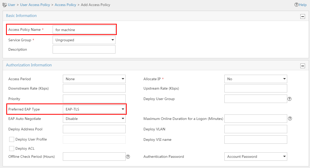
3. Add an access service.
¡ If the user-name-format with-domain command is configured on the device, use the default domain name as the service suffix.
¡ If the user-name-format without-domain command is configured on the device, leave the Service Suffix field empty.
Figure 92 shows the default access policy configurations. Figure 93 shows the configurations of a sample access policy.
Figure 92 Default access policy
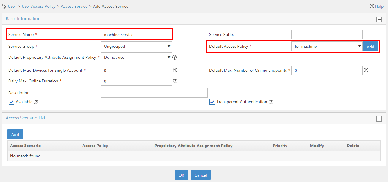
Figure 93 Configurations of a sample access policy
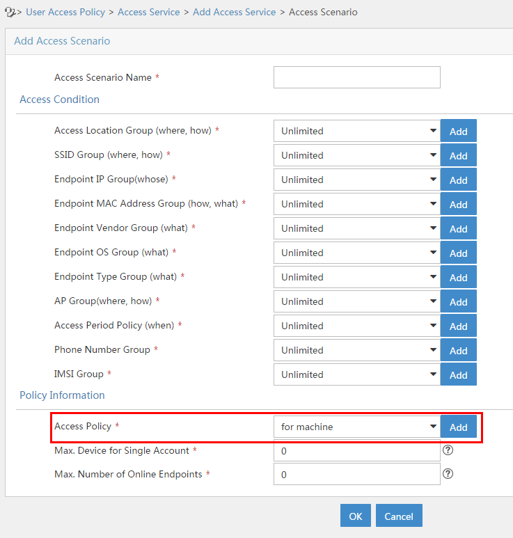
4. Add a computer user and assigns the added service to the user.
The account name of a computer user is computer. The online user list displays the account name as computer for all computer users who have passed authentication.
Figure 94 Adding a computer user
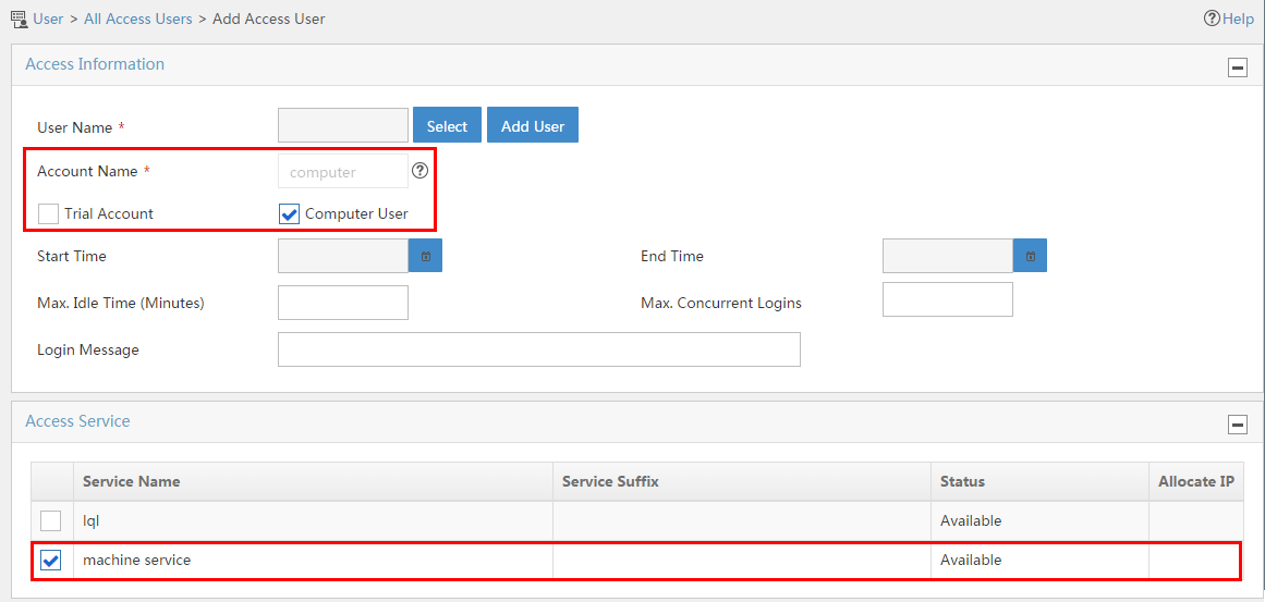
5. Import the root and server certificates to UAM.
Configuring the access device
1. Configure a RADIUS scheme.
¡ The RADIUS scheme parameters configured on the device must be the same as those configured in UAM.
¡ If the access user is assigned a service with a suffix, configure the device to add domain information to the user names to be sent to the RADIUS servers. If the access user is assigned a service without any suffix, configure the device to remove domain information from the user names to be sent to the RADIUS servers.
2. Configure an ISP domain.
a. Create an ISP domain and configure the domain to use the RADIUS scheme for 802.1X users.
b. Configure the domain as the default ISP domain.
If the access user is assigned a service with a suffix, the domain name must be the same as the service suffix. If the access user is assigned a service without any suffix, use any domain name.
3. Configure 802.1X authentication.
a. Enable 802.1X globally and on the interface that connects to the computer.
Configuring the iNode PC client
1. Download and install the root and client certificates.
The client certificate name is the complete computer name. If the computer joins a domain, the login name includes the domain name.
The Online User List displays the login name of access users that have passed authentication as the computer name.
2. Create a common connection for 802.1X authentication in the iNode PC client.
a. Set the user name and password for 802.1X authentication.
Figure 95 Setting a user name and password for 802.1X authentication
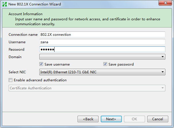
b. On the Network Property Settings page, select Machine Authentication, and the Auto authN after startup option is automatically selected. With the configuration, the iNode PC client automatically performs 802.1X authentication after computer authentication succeeds.
Figure 96 Configuring computer authentication
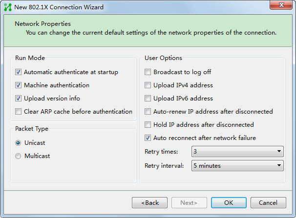
Using the built-in Windows 802.1X client
Configuring UAM
See "Configuring UAM."
Configuring the access device
The configurations on the access device are the same as those described in "Configuring the access device," except that you must disable 802.1X handshake on the interface that connects to the computer. The Windows built-in client does not support 802.1X handshake.
Configuring the Windows host
1. Enable IEEE 802.1X authentication in Windows.
2. Install the client and root certificates.
The client certificate name is the complete computer name. If the computer joins a domain, the login name includes the domain name.
The Online User List displays the login name of access users that have passed authentication as the computer name.
3. Configure the network card for 802.1X authentication:
a. In the Local Area Connection Properties dialog box, select Enable IEEE 802.1X authentication.
b. Select Microsoft: Smart Card or other certificate as the network authentication method.
c. Select Remember my credentials for this connection each time I’m logged on to automatically process subsequent network access requests.
d. Click Settings.
Figure 97 Configuring the network card for 802.1X authentication
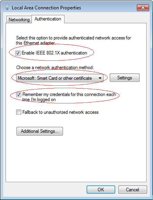
e. In the Smart Card or other Certificate Properties dialog box, select the following options:
- Use a certificate on this computer
- Use simple certificate selection (Recommended)
- Validate server certificate
- CA server (08R2-SQL08R2-88-CA in this example) on the Trusted Root Certification Authorities list.
Figure 98 Configuring the smart card or other certificate properties
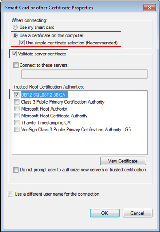
g. In the Local Area Connection Properties dialog box, click Additional Settings.
h. In the Advanced settings dialog box, select Specify authentication mode, select Computer authentication from the list, and click OK.
i. In the Local Area Connection Properties dialog box, click OK.
Figure 99 Configuring the advanced settings
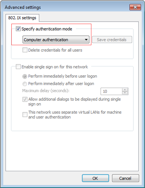
Configuring LDAP authentication
In a network that uses an LDAP server for user management, you can synchronize user accounts from the LDAP server to UAM instead of adding them manually. Users of these accounts are called LDAP users.
When the authentication request from a user arrives, UAM looks up the user in the local user database. If the user is an LDAP user, UAM forwards the request to the LDAP server. If the user is not an LDAP user, UAM directly authenticates the user. Figure 100 shows the authentication process.
Figure 100 LDAP authentication
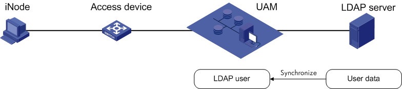
UAM works with most LDAP servers in the market, including Microsoft Windows Active Directory, Open LDAP, Sun ONE LDAP Server, and Novell eDirectory Server.
Managing LDAP servers
An LDAP server stores user data and verifies user identities in LDAP authentication.
Accessing the LDAP server list page
1. Click the User tab.
2. From the navigation tree, select User Access Policy > LDAP Service > LDAP Server.
The list includes all LDAP servers.
LDAP server list contents
¡ Server Name—LDAP server name.
¡ Version—Version of the LDAP protocol running on the LDAP server. UAM supports LDAPv2 and LDAPv3.
¡ Address—Domain name or IP address of the LDAP server.
¡ Server Type—Type of the LDAP server: Microsoft AD or General (any server type, including Microsoft Windows AD). To use Microsoft Windows AD specific functions like AD-based service assignment, you must set the server type to Microsoft AD. In any other cases, set the server type to General.
¡ Service Sync Type—The way you assign services to LDAP users:
- Manual Assignment—Assign services directly to LDAP users when you configure a synchronization policy for the LDAP server.
- Based On Active Directory Group—Assign services to LDAP AD groups when you configure a synchronization policy for the LDAP server. UAM assigns services to users depending on their LDAP AD groups. For more information, see "Adding a policy when the Service Sync Type is based on AD group."
¡ User Group—User group to which the users synchronized from the LDAP server to UAM belong, which can be Manual Specify or Synchronize by OU. Manual Specify indicates all LDAP users are synchronized to the user group that is specified in the synchronization policy assigned to the LDAP server. Synchronize by OU indicates that UAM builds user groups based on the OU structure in the base DN of the LDAP server, and synchronizes LDAP users to their respective user groups.
¡ Service Group—Service group that the LDAP server belongs to.
¡ Test—Click the Test link to test connectivity to the LDAP server.
¡ Modify—Click the Modify icon ![]() to modify the settings of the LDAP server.
to modify the settings of the LDAP server.
¡ Delete—Click the Delete icon ![]() to delete the LDAP server.
to delete the LDAP server.
¡ Certificate—Click the Configure icon ![]() for an LDAP server to display the certificate import wizard. You
must import certificates to UAM if you have enabled the
Use SSL function for the
LDAP server. For more information, see "Importing certificates."
for an LDAP server to display the certificate import wizard. You
must import certificates to UAM if you have enabled the
Use SSL function for the
LDAP server. For more information, see "Importing certificates."
Viewing LDAP server details
1. Access the LDAP server list page.
2. Click the name of the LDAP server whose details you want to view.
The LDAP Server Information page opens.
Basic Information area
¡ Server Name—LDAP server name.
¡ Version—Version of the LDAP protocol running on the LDAP server. UAM supports LDAPv2 and LDAPv3.
¡ Address—Domain name or IP address of the LDAP server.
¡ Port—TCP port to which the LDAP server listens for packets sent by UAM.
¡ Server Type—Type of the LDAP server: Microsoft AD or General (any server type, including Microsoft Windows AD). Microsoft Windows AD specific functions like AD-based service assignment are only available for Microsoft AD servers.
¡ Service Sync Type—The way you assign services to LDAP users.
- Manual Assignment—Assign services directly to LDAP users when you configure a synchronization policy for the LDAP server.
- Based On Active Directory Group—Assign services to LDAP AD groups when you configure a synchronization policy for the LDAP server. UAM assigns services to users depending on their LDAP AD groups. For more information about LDAP synchronization policies, see "Adding a policy when the Service Sync Type is based on AD group."
¡ Real Time AuthN—Displays whether authentication is performed by the LDAP server.
- Yes—LDAP users are authenticated on the LDAP server.
- No—LDAP users are authenticated on UAM.
¡ Reconnect Interval—Time UAM waits before retrying to connect to the LDAP server after a connection failure. During this interval, UAM does not try to connect to the LDAP server or accept any authentication request that must be forwarded to the LDAP server. After the interval expires, UAM retries to connect to the LDAP server.
¡ Connection Wait Time—Time period within which if UAM fails to connect to the LDAP server, the connection attempt is considered failed.
¡ Sync Wait Time—Maximum duration of each synchronization. The sync wait timer starts when UAM starts synchronizing user data from the LDAP server. When this timer expires, UAM stops the synchronization, regardless of whether the synchronization is completed or not. If you do not want to set a time limit, set the timer to 0.
¡ User Group—User group to which the users synchronized from the LDAP server to UAM belong.
- Manual Specify—All LDAP users are synchronized to the user group that is specified in the synchronization policy assigned to the LDAP server.
- Synchronize by OU—UAM builds user groups based on the OU structure in the base DN of the LDAP server, and synchronizes LDAP users to their respective user groups.
¡ Parent Group—Parent user group of the user group to which the users synchronized from the LDAP server to UAM belong. If the field is empty, UAM creates the level 1 user group based on the topmost level of the OU hierarchy on the LDAP server. This field is displayed only when the User Group field displays Synchronize by OU.
¡ Service Group—Service group that the LDAP server belongs to. Each service group represents a set of assignable authorizations.
¡ Connectivity—If UAM failed to connect to the LDAP server, this field displays Not Connected within the reconnect interval. Otherwise, this field displays Connected.
¡ Use SSL—If SSL runs between UAM and the LDAP server for encryption, this field displays Yes. Otherwise, this field displays No. This parameter is displayed only when IMC is installed on the Windows server.
Server Information area
¡ Base DN—Absolute path of the directory that stores user data on the LDAP server.
¡ Admin DN—Administrator on the LDAP server, displayed as the absolute path on the LDAP server.
¡ User Name Attribute—Attribute description used on the LDAP server for user names.
¡ Password Attribute—Attribute description used on the LDAP server for user passwords, which also serve as LDAP user passwords in UAM. For more information, see "Supplementary information for LDAP user passwords stored in UAM."
¡ Account Format—Because the attributes on the LDAP server contain some redundant information, UAM might need to trim the account names obtained from the LDAP server.
Valid values for this parameter include:
- Unchanged—Does not change the account names.
- Remove Prefix—Removes the prefix of an account name.
- Remove Suffix—Removes the suffix of an account name.
- Add Prefix—Adds a prefix before an account name.
¡ Delimiter—Case-sensitive string used to separate the trimmed characters from the remaining characters. For example, if you select Remove Prefix and set the delimiter to an at sign (@) for account [email protected], the remaining account name is test.com. If you select Remove Suffix and set the delimiter to a dot (.) for the account, the remaining account name is Jack@test.
The parameter is displayed only when Remove Prefix or Remove Suffix is selected.
¡ Prefix—String to be added before an account name. The prefix is separated from the account name by a forward slash (/). For example, if you set the prefix to uam for account guest, the resulting account name is uam/guest.
This parameter is displayed only when Add Prefix is selected and the LDAP server type is Microsoft AD.
¡ Password Policy—Policy an LDAP user must comply with when modifying the password. This policy must be consistent with the password policy configured on the LDAP server. This parameter is displayed only when the server type is set to Microsoft AD and SSL is used to encrypt the packets exchanged between UAM and the LDAP server.
Standby Server Information area
¡ Address—Domain name or IP address of the standby LDAP server. UAM sends the authentication requests of LDAP users to this server after the primary LDAP server becomes unavailable.
¡ Server in Use—LDAP server being used for authenticating LDAP users.
¡ Auto Back to Primary—When the primary LDAP server becomes unavailable, UAM switches over to the standby server and starts regularly checking the availability of the primary server.
- If the Auto Back to Primary setting is Yes, UAM automatically switches back to the primary server after the server becomes available.
- If the Auto Back to Primary setting is No, UAM continues to use the standby server.
¡ Interval—Minimum interval between a primary-to-standby switchover and an automatic back-to-primary switchover.
This setting takes effect only when auto back to primary is enabled. UAM can automatically switch back to the primary server only if the standby server has been working for a period equal to or longer than this interval since the primary-to-standby switchover.
MS-CHAPv2 Authentication area
The following parameters are displayed when MS-CHAPv2 authentication is enabled:
¡ Domain Controller Address—Domain name or IP address of the domain controller.
¡ Standby Domain Controller Address—Domain name or IP address of the standby domain controller.
¡ Domain Controller Full Name—Full name of the domain controller.
¡ Standby Domain Controller Full Name—Full name of the standby domain controller.
¡ Virtual Computer Name—Name of the virtual computer used by the domain controller to communicate with UAM.
3. To return to the LDAP server list page, click Back.
Adding an LDAP server
1. Access the LDAP server list page.
2. Click Add.
3. Configure the following basic information:
¡ Server Name—Enter the LDAP server name, which must be unique in UAM.
¡ Version—Select an LDAP protocol version (V2 or V3) from the list.
¡ Address—Enter the domain name or IP address of the LDAP server. If the LDAP server has more than one NIC, enter the IP address of the NIC used for communicating with UAM.
¡ Port—Enter the TCP port number to which the LDAP server listens for the packets from UAM. The default port number is 389, which is used by most LDAP servers.
¡ Server Type—Select an LDAP server type: Microsoft AD or General (any server type, including Microsoft Windows AD).
- To use Microsoft Windows AD specific functions like AD-based service assignment, you must set the server type to Microsoft AD. If the server type is set to Microsoft AD, LDAP user authentication must be performed by the LDAP server.
- In any other cases, set the server type to General.
For the compatibility matrix of Server Type, Service Sync Type, and Real Time AuthN settings, see Table 30.
Table 30 Matrix of server type, service sync type, and Real Time AuthN
|
Server Type |
Service Sync Type |
Real Time AuthN |
|
General |
Manual assignment |
Yes or No |
|
Microsoft AD |
· Manual assignment · AD group based |
Yes |
¡ Service Sync Type—Select a service synchronization type from the list: Manual assignment or Based On Active Directory Group.
The services assigned to the LDAP users synchronized from the LDAP server are determined by the following parameters: Service Sync Type, Apply for Service by User Group, and User Group. For the basic matrix of related parameters, see Table 31.
For more information about the Apply for Service by User Group feature, see "Configuring global system settings."
Table 31 Basic matrix of related parameters for services
|
Service sync type |
Apply for service by user group |
User group sync mode |
Services applied for by the LDAP users |
|
Manual assignment |
Enabled |
Synchronize by OU |
No other configuration is needed for the LDAP synchronization policy to be assigned to the LDAP server. UAM builds user groups based on the OU structure in the base DN of the LDAP server, and synchronizes LDAP users to their respective user groups. UAM automatically applies for services for each LDAP user, and the services to be applied for are those assigned to their respective user groups. |
|
Manual Specify |
When assigning an LDAP synchronization policy to the LDAP server, operators must specify a user group for the LDAP users. UAM applies for the services assigned to the specified user group for all LDAP users. |
||
|
Disabled |
N/A |
When assigning an LDAP synchronization policy to the LDAP server, operators must select the services to be assigned to LDAP users. UAM applies for the selected services for all LDAP users. |
|
|
Based on active directory group |
N/A |
N/A |
When assigning an LDAP synchronization policy to the LDAP server, operators assign services only to LDAP AD groups. UAM automatically applies for services for each LDAP user, and the services to be applied for are those assigned to their respective LDAP AD groups. For information about configuring such LDAP synchronization policies, see "Adding a policy when the Service Sync Type is based on AD group." |
¡ Real Time AuthN—Displays whether authentication is performed by the LDAP server.
- Yes—LDAP users are authenticated on the LDAP server.
- No—LDAP users are authenticated on UAM.
For the compatibility matrix of Server Type, Service Sync Type, and Real Time AuthN settings, see Table 30.
¡ Reconnect Interval—Select the time that UAM must wait before retrying to connect to the LDAP server after a connection failure.
If you select Do Not Connect Auto, you disable UAM from automatically retrying to connect to the LDAP server after a connection failure.
¡ Connection Wait Time—Enter the maximum duration of each connection attempt. If UAM fails to connect to the LDAP server within this period, the connection attempt is considered failed.
¡ Sync Wait Time—Set the maximum duration of each synchronization process. The sync wait timer starts when UAM starts synchronizing user data from the LDAP server. When this timer expires, UAM stops the synchronization, regardless of whether the synchronization is completed or not.
If you do not want to set a time limit, set the timer to 0.
¡ User Group—Select Manual Specify or Synchronize by OU from the list.
- Manual Specify—All LDAP users are synchronized to the user group that is specified in the synchronization policy assigned to the LDAP server.
- Synchronize by OU—UAM builds user groups based on the OU structure in the base DN of the LDAP server, and synchronizes LDAP users to their respective user groups.
¡ Parent Group—This option is displayed only when Synchronize by OU is selected for the User Group field.
Click the Select User Group icon ![]() to select a group
in the Select User Group window. The selected user group will become
the root parent user group of all user groups synchronized from the LDAP server
to UAM.
to select a group
in the Select User Group window. The selected user group will become
the root parent user group of all user groups synchronized from the LDAP server
to UAM.
If you leave this field empty, UAM uses the topmost level of the OU hierarchy on the LDAP server as the root user group.
You cannot select Ungrouped as the parent group. Otherwise, UAM displays an error message upon completion of adding the LDAP server.
UAM supports a user group hierarchy of at most five levels, and does not synchronize LDAP OUs that correspond to level 6 or lower level user groups. For example, if you select a level 2 user group as the parent group, UAM can further synchronize at most three levels of OUs from the LDAP server and ignores level 4 or lower level OUs.
¡ Service Group—Select a service group for the LDAP server from the list. Available options include all service groups that have been created in UAM and Ungrouped.
¡ Use SSL—Select the option to use SSL to encrypt the packets exchanged between UAM and the LDAP server. When this option is selected, you must import associated certificates to UAM. For more information, see "Importing certificates."
4. Configure server information.
UAM uses the Administrator DN and password to authenticate to the LDAP server, navigates to the user data directory according to the base DN, and gets the values in the user name and password attributes, and adds the user name and password pairs to its user database.
The base DN, administrator DN, user name, and password attribute descriptions vary with LDAP servers. You can use a tool such as Softerra LDAP Administrator to get attribute descriptions on the server you are working with.
¡ Base DN—Enter the absolute path of the directory that stores user data in the LDAP server.
¡ Admin DN—Enter the absolute path that locates the administrator on the LDAP server.
¡ Admin Password—Enter the administrator password.
¡ User Name Attribute—Enter the attribute description used on the LDAP server for user names.
¡ Password Attribute—Enter the attribute description used on the LDAP server for user passwords.
This parameter does not need to be configured when the Server Type is Microsoft AD, whose user passwords are not readable.
The password attribute values in UAM correspond to user passwords in the LDAP server. For more information, see "Supplementary information for LDAP user passwords stored in UAM."
¡ User Password Encryption—Select the mode that UAM uses to encrypt user passwords. If you select Autosense, UAM uses the user password encryption mode on the LDAP server. If you select Not encrypted, UAM does not encrypt user passwords. To select Not encrypted or a specific password encryption mode, make sure the password encryption mode is consistent with that on the LDAP server.
¡ Support Bind Requests—Select whether to enable the support for password verification by processing bind requests. Options are Yes and No.
¡ Password Policy—Policy an LDAP user must comply with when modifying the password. This policy must be consistent with the password policy configured on the LDAP server. This parameter is displayed only when the following requirements are met:
- The server type is set to Microsoft AD.
- SSL is used to encrypt the packets exchanged between UAM and the LDAP server.
- The User must change password at next logon option is selected on the LDAP server.
¡ Account Format—Select the way in which UAM handles account names obtained from the LDAP server:
- Unchanged—Does not change the account names.
- Remove Prefix—Removes the prefix of an account name.
- Remove Suffix—Removes the suffix of an account name.
- Add Prefix—Adds a prefix before an account name.
¡ Delimiter—Enter a case-sensitive string that separates the trimmed characters from the remaining characters. For example, if you select Remove Prefix and set the delimiter to an at sign (@) for account [email protected], the remaining account name is test.com. If you select Remove Suffix and set the delimiter to a dot (.) for the account, the remaining account name is Jack@test.
The parameter is displayed only when Remove Prefix or Remove Suffix is selected.
¡ Prefix—Enter the prefix to be added before an account name. The prefix is separated from the account name by a forward slash (/). For example, if you set the prefix to uam for account guest, the resulting account name is uam/guest.
This parameter is displayed only when Add Prefix is selected and the LDAP server type is Microsoft AD.
5. To provide non-stop services, configure a standby server to provide authentication for the LDAP users when the primary server is unavailable. The primary to standby switchover takes about 1 minute. During this period, all network access requests from LDAP users are rejected. However, the switchover does not affect any online user.
¡ Address—Enter the IP address or domain name of the standby LDAP server.
¡ Server in Use—Select the LDAP server being used for authenticating LDAP users.
¡ Auto Back to Primary—Select the option if you want UAM to automatically stop using the standby server and switch back to the primary server after the server becomes available. Otherwise, UAM continues to use the standby server. This parameter does not take effect if you set Server in Use to Standby.
¡ Interval—Enter the minimum interval between a primary-to-standby switchover and an automatic back-to-primary switchover. This parameter takes effect only when Auto Back to Primary is enabled. UAM can automatically switch back to the primary server only if the standby server has been working for a period equal to or longer than this interval since the primary-to-standby switchover.
6. To perform MS-CHAPv2 authentication on LDAP users, select the MS-CHAPv2 Authentication option and configure the following parameters:
¡ Use IP Addresses of LDAP Servers—Select this option to enable local MS-CHAPv2 authentication for LDAP users. The LDAP server address and standby LDAP server address are used as the domain controller address and standby domain controller address, respectively.
¡ Domain Controller Address—Enter the domain name or IP address of the domain controller. For example, if the full name of the domain controller is ad.hpe.com, you can enter the domain name hpe.com as the domain controller address.
¡ Standby Domain Controller Address—Enter the domain name or IP address of the standby domain controller. For example, if the full name of the standby domain controller is ad.hpe.com, you can enter the domain name hpe.com as the standby domain controller address.
¡ Domain Controller Full Name—Enter the full name of the domain controller. To view the domain controller name, right-click the My Computer icon, select Properties, and view the full computer name under the Computer name, domain, and workgroup settings tab.
¡ Standby Domain Controller Full Name—Enter the full name of the standby domain controller. To view the full name of the standby domain controller, right-click the My Computer icon, select Properties, and view the full computer name under the Computer name, domain, and workgroup settings tab.
¡ Virtual Computer Name—Enter the name of the virtual computer used by the domain controller to communicate with UAM. The value must be the same as the name of the virtual computer created in the Computers directory of the domain controller.
¡ Virtual Computer Password/Confirm Virtual Computer Password—Enter and confirm the password of the virtual computer. The value must be the same as the virtual computer's password configured on the domain controller. UAM enables you to modify the virtual computer's password on the domain controller by using a script. For more information, see "Configuring LDAP parameters."
|
|
IMPORTANT: MS-CHAPv2 authentication settings must be consistent on all LDAP servers of the same IP address. If you modify the MS-CHAPv2 authentication settings on an LDAP server, UAM automatically applies the settings to all other LDAP servers that have the same IP address as the LDAP server. |
7. Click Test to test the connectivity to the LDAP server. If the connection attempt fails, follow the displayed tips to check for configuration errors.
8. Click OK.
Testing connectivity to an LDAP server
1. Access the LDAP server list page.
2. Click Test for the LDAP server.
The test result is displayed at the top of the page. If the LDAP server fails to be connected, follow the displayed tips to check for LDAP server configuration errors.
Modifying LDAP server settings
1. Access the LDAP server list page.
2. Click the Modify
icon ![]() for the LDAP server
you want to modify.
for the LDAP server
you want to modify.
The Modify LDAP Server page opens.
3. Modify basic information:
¡ Version—Select the version of the LDAP protocol running on the LDAP server from the list. UAM supports LDAPv2 and LDAPv3.
¡ IP Address—Enter the IP address of the LDAP server. If the LDAP server has more than one NIC, enter the IP address of the NIC used for communicating with UAM.
¡ Port—Enter the TCP port number to which the LDAP server listens for packets sent by UAM. The default port number is 389, which is used by most LDAP servers.
¡ Reconnect Interval—Select the time that UAM must wait before retrying to connect to the LDAP server after a connection failure, or select Do Not Connect Auto to disable UAM from automatically retrying to connect to the LDAP server after a connection failure.
During this interval, UAM does not try to connect to the LDAP server or accept any authentication request that must be forwarded to the server. After the interval expires, UAM retries to connect to the LDAP server.
¡ Connection Wait Time—Enter the maximum duration of each connection attempt. If UAM fails to connect to the LDAP server within this period, the connection attempt is considered failed.
¡ Sync Wait Time—Enter the maximum duration of each synchronization. The sync wait timer starts when UAM starts synchronizing user data from the LDAP server. When this timer expires, UAM stops the synchronization, regardless of whether the synchronization is completed or not. If you do not want to set a time limit, set the timer to 0.
¡ Use SSL—Select the option to use SSL to encrypt the packets exchanged between UAM and the LDAP server. When this function is enabled, you must import associated certificates to UAM. For more information about importing certificates, see "Importing certificates." This parameter is displayed only when IMC is installed on the Windows server.
¡ Connectivity—If UAM failed to connect to the LDAP server, the field displays Unconnected within the reconnect interval. If UAM has successfully connected to the LDAP server, the field displays Connected. You can manually modify the connectivity status.
Other parameters cannot be modified.
4. Modify server information:
¡ Admin DN—Enter the absolute path that locates the administrator on the LDAP server.
¡ Admin Password—Enter the administrator password.
¡ User Attribute Name—Enter the attribute description used on the LDAP server for user names.
¡ Password Attribute—Enter the attribute description used on the LDAP server for user password. This parameter does not need to be configured when the Server Type is Microsoft AD, whose user passwords are not readable. The password attribute values in UAM correspond to user passwords in the LDAP server. For more information, see "Supplementary information for LDAP user passwords stored in UAM."
¡ Password Policy—Policy an LDAP user must comply with when modifying the password. This parameter is displayed only when the following requirements are met:
- The server type is set to Microsoft AD.
- SSL is used to encrypt the packets exchanged between UAM and the LDAP server.
- The User must change password at next logon option is selected on the LDAP server.
Other parameters cannot be modified. For more information, see "Adding an LDAP server."
5. Modify standby server information:
¡ Address—Enter the IP address or domain name of the standby LDAP server.
¡ Server in Use—Select the LDAP server being used for authenticating LDAP users.
¡ Auto Back to Primary—Select the option to enable Auto Back to Primary. When the primary LDAP server becomes unavailable, UAM switches over to the standby server and starts regularly checking the availability of the primary server. If the option is enabled, UAM automatically switches back to the primary server after the server becomes available.
If the option is disabled, UAM continues to use the standby server. This parameter does not take effect if you select Standby for Server in Use.
¡ Interval—Enter the minimum interval between a primary-to-standby switchover and an automatic back-to-primary switchover. This parameter takes effect only when Auto Back to Primary is enabled. UAM can automatically switch back to the primary server only if the standby server has been working for a period equal to or longer than this interval since the primary-to-standby switchover.
6. Modify PEAP-MSCHAPv2 authentication:
To perform MS-CHAPv2 authentication on LDAP users, select the MS-CHAPv2 Authentication option and configure the following parameters:
¡ Use IP Addresses of LDAP Servers—Select this option to enable local MS-CHAPv2 authentication for LDAP users. The LDAP server address and standby LDAP server address are used as the domain controller address and standby LDAP server address, respectively.
¡ Domain Controller Address—Enter the domain name or IP address of the domain controller. For example, if the full name of the domain controller is ad.hpe.com, you can enter the domain name hpe.com as the domain controller address.
¡ Standby Domain Controller Address—Enter the domain name or IP address of the standby domain controller. For example, if the full name of the standby domain controller is ad.hpe.com, you can enter the domain name hpe.com as the standby domain controller address.
¡ Domain Controller Full Name—Enter the full name of the domain controller. To view the domain controller name, right-click the My Computer icon, select Properties, and view the full computer name under the Computer name, domain, and workgroup settings tab.
¡ Standby Domain Controller Full Name—Enter the full name of the standby domain controller. To view the full name of the standby domain controller, right-click the My Computer icon, select Properties, and view the full computer name under the Computer name, domain, and workgroup settings tab.
¡ Virtual Computer Name—Enter the name of the virtual computer used by the domain controller to communicate with UAM. The value must be the same as the name of the virtual computer created in the Computers directory of the domain controller.
¡ Virtual Computer Password/Confirm Virtual Computer Password—Enter and confirm the password of the virtual computer. The value must be the same as the virtual computer's password configured on the domain controller. UAM enables you to modify the virtual computer's password on the domain controller by using a script. For more information, see "Configuring LDAP parameters."
If the domain controller with the same IP address is configured for other LDAP servers, the servers use the current MS-CHAPv2 authentication settings.
|
|
IMPORTANT: MS-CHAPv2 authentication settings must be consistent on all LDAP servers of the same IP address. If you modify the MS-CHAPv2 authentication settings on an LDAP server, UAM automatically applies the settings to all other LDAP servers that have the same IP address as the LDAP server. |
7. Click Test to test the connectivity to the LDAP server. If the connection attempt fails, follow the displayed tips to check for configuration errors.
8. Click OK.
If the LDAP server has been associated with a policy that performs synchronization on an as-needed basis and you have changed the password or user name attribute description, click On-Demand Sync on the synchronization policy page to validate the change.
For more information, see "Managing LDAP synchronization policies."
Deleting an LDAP server
You can delete LDAP servers that are not associated with LDAP synchronization policies.
When an LDAP server is deleted, UAM automatically removes all empty user groups that are synchronized from the LDAP server and do not contain sub-groups or users.
To delete an LDAP server:
1. Access the LDAP server list page.
2. Click the Delete
icon ![]() for the LDAP server you want to delete.
for the LDAP server you want to delete.
A confirmation dialog box opens.
3. Click OK.
Importing certificates
To deliver SSL-based authentication between UAM and the LDAP server, you have to:
· Enable the SSL function on the LDAP server, and import the certificate required for SSL authentication to the server. For specific procedures, see the related LDAP server configuration guide.
Select the Use SSL option when adding or modifying the LDAP server in UAM. For specific procedures, see "Managing LDAP servers."
· Import the root certificate that is associated with the LDAP server certificate to UAM.
IMC supports the following server certificate file formats:
¡ PEM—Base64 encoded, with a file suffix .pem or .cer.
¡ DER—DER encoded, with a file suffix .der or .cer.
¡ PKCS12—PKCS 12 encoded, with a file suffix .pfx or .p12.
To import certificates to UAM:
1. Access the LDAP Server List page.
2. Click the Configure
icon ![]() for an LDAP server to display the certificate import wizard.
for an LDAP server to display the certificate import wizard.
3. Configure Add Root Certificate.
4. Click Browse in the Root Certificate area to select a locally saved root certificate.
5. Click Next to display the Certificate Preview page.
6. Verify the displayed root certificate information and click OK.
Batch-modifying LDAP server admin passwords
UAM allows you to modify LDAP server admin passwords in batches to facilitate maintenance.
To batch modify LDAP server admin passwords:
1. Access the LDAP server list page.
2. Select one or more LDAP servers.
3. Click Modify Admin Password to display the page for modifying the administrative password.
4. Enter the new administrative password for the selected LDAP servers.
5. Click OK.
Synchronizing user groups
UAM supports synchronizing user groups in the following ways:
· UAM can execute an LDAP synchronization policy to automatically build user groups based on the OU structure in the LDAP server and synchronize LDAP users to their respective user groups. If an LDAP user has moved from one OU to another, IMC also moves the LDAP user to the corresponding user group accordingly. For information about manually executing an LDAP synchronization policy, see "Manually executing a synchronization policy."
· Operators can manually trigger an OU structure synchronization. In this case, UAM builds only user groups based on the OU structure without synchronizing any users from the LDAP server.
The following rules apply during user group synchronization:
· If a new OU is found on the LDAP server, UAM creates a user group for the OU.
· If an OU has been removed from the LDAP server, UAM checks whether the corresponding user group contains users. If it does, UAM keeps the user group. Otherwise, UAM deletes the user group.
To synchronize only the user groups from LDAP servers:
1. Access the LDAP server list page.
2. Click Synchronize.
If no server in the LDAP server list is configured to build user groups based on OUs, the Synchronize button is unavailable.
After the synchronization is completed, UAM displays numbers of successfully added user groups, deleted user groups, and operation failures. If failures exist, click Download to download or view the reasons for failure in the operation log.
Managing LDAP synchronization policies
An LDAP synchronization policy determines:
· How you synchronize user data from an LDAP server to UAM.
· The scope of user data.
· How the user data is handled on UAM.
Users synchronized from the LDAP server become access users or device management users in UAM.
An LDAP synchronization policy can be bound to only one LDAP server, but an LDAP server can have multiple LDAP synchronization policies.
Accessing the LDAP synchronization policy list page
1. Click the User tab.
2. From the navigation tree, select User Access Policy > LDAP Service > Sync Policy.
The list includes all the LDAP synchronization policies.
Synchronization policy list contents
¡ Policy Name—LDAP synchronization policy name. This parameter displays detailed policy information.
¡ Server Name—LDAP server name associated with the LDAP synchronization policy name. This parameter displays detailed LDAP server information.
¡ Sync Object—User type of the synchronization policy:
- Access Users—The policy synchronizes users from the LDAP server to UAM as access users.
- Device Users—The policy synchronizes users from the LDAP server to UAM as device management users.
¡ Service Group—Service group to which the policy is assigned. It is always the same as the service group to which the LDAP server is assigned.
¡ Status—Validity of the synchronization policy: Valid or Invalid.
¡ Synchronization Priority—Priority of the LDAP synchronization policy. Synchronization policies with higher priority values are executed first in a scheduled synchronization task.
¡ Synchronize Users as Needed—Enable this option to save user account licenses.
- If this option is enabled, UAM synchronizes a new user from the LDAP server only after the user passes authentication.
- If this option is disabled, UAM synchronizes all the matching users from the LDAP server.
¡ Bind User—Displays a Bind User icon ![]() or empty.
or empty.
- If the Sync Object is Access Users, this field provides a Bind User icon ![]() . Click the icon to view users that are bound to the policy. For more information about managing
LDAP users, see "Managing LDAP users."
. Click the icon to view users that are bound to the policy. For more information about managing
LDAP users, see "Managing LDAP users."
- If the Sync Object is Device Users, this field is empty.
¡ Synchronize—Click the Synchronize link for a synchronization policy link to execute the policy.
¡ Modify—Click the Modify icon ![]() to display the page
for modifying the LDAP synchronization
policy.
to display the page
for modifying the LDAP synchronization
policy.
¡ Delete—Click the Delete icon ![]() to delete the LDAP synchronization
policy.
to delete the LDAP synchronization
policy.
Querying LDAP synchronization policies
1. Access the LDAP synchronization policy list page.
2. Specify one or more of the following query criteria in the Query Sync Policies area:
¡ Policy Name—Enter a partial or complete LDAP synchronization policy name. For example, if you enter lab, all policy names that contain lab are matched.
¡ Server Name—Select the LDAP server from the list.
¡ User Group—Click the Select User Group icon ![]() . The Select User Group window opens. Select a group and click OK. You can select only one user group for query. Because
device users cannot be grouped, if you select a user group, any synchronization
policy with the Sync Object set to
Device Users cannot be queried.
. The Select User Group window opens. Select a group and click OK. You can select only one user group for query. Because
device users cannot be grouped, if you select a user group, any synchronization
policy with the Sync Object set to
Device Users cannot be queried.
¡ Sync Object—Select a user type from the list. Options include Access Users and Device Users.
¡ Service Group—Select from the list a service group configured in UAM.
The query ignores empty fields.
3. Click Query.
The list includes all LDAP synchronization policies that match the query criteria.
To clear the query criteria, click Reset. The list includes all LDAP synchronization policies.
Viewing LDAP synchronization policy details
The Sync Policy Information page contents vary with the policy synchronization object, which can be Access Users or Device Users.
Viewing policy information whose Sync Object is Access Users
To view detailed information about a synchronization policy whose Sync Object is Access Users:
1. Access the LDAP synchronization policy list page.
2. Click the name of an LDAP synchronization policy whose Sync Object is set to Access Users.
The Sync Policy Information page opens.
Sync Policy Basic Information area
¡ Policy Name—LDAP synchronization policy name.
¡ Server Name—LDAP server name.
¡ Base DN—Absolute path of the base directory that stores user data in the LDAP server.
¡ Sub-Base DN—Absolute path of the subdirectory that stores user data in the LDAP server. UAM synchronizes only the user data under the specified subdirectory from the server.
¡ Filter Condition—Filter criteria for the synchronization policy. Only users who match these criteria can be synchronized to UAM.
¡ States—Policy usability state: Valid or Invalid.
¡ Synchronization Priority—Priority of the LDAP synchronization policy. Synchronization policies with higher priority values are executed first in a scheduled synchronization task.
¡ Auto Synchronization—Automatic synchronization status.
- If this option is enabled (Yes), UAM automatically executes the synchronization policy every day as scheduled. The execution time depends on the system settings for scheduled daily tasks.
- If this option is disabled (No), UAM performs synchronization on an as-needed basis.
¡ Synchronize Users as Needed—You can enable this option to save user account licenses.
- If this option is enabled (Yes), UAM synchronizes a new user from the LDAP server only after the user passes authentication.
- If this option is disabled (No), UAM synchronizes all the matching users from the LDAP server.
¡ Synchronize New Users and Accounts—If this option is enabled (Yes), UAM synchronizes users that are not in the IMC platform's user database from the LDAP server, adds these users to the IMC platform and creates associated access user accounts in the UAM database. If this option is disabled (No), UAM does not synchronize users that are not in the IMC platform.
¡ Synchronize New Accounts of Existing Users—If this option is enabled (Yes), UAM adds an associated access account for a user during synchronization when both the following requirements are met:
- The user exists both in the IMC platform and the LDAP server.
- The user does not have an access user account in UAM.
If this option is disabled (No), UAM does not add access accounts for such users.
¡ Synchronize Users in Current Node Only—If this option is enabled (Yes), UAM synchronizes users directly under the specified sub-base DN, but does not synchronize users in any OU under the sub-base DN. If this option is disabled (No), UAM synchronizes all users in the sub-base DN, including users in the OUs in the sub-base DN.
¡ Inherit Parent Group's Service—This option is displayed only when the selected LDAP server uses the following settings:
- Manual Assignment is selected for the Service Sync Type field.
- The Apply for Service by User Group option is enabled.
- Synchronize by OU is selected for the User Group field.
With the Inherit Parent Group's Service option enabled, UAM applies for the services of the parent user group for the LDAP users who belong to a group of no service.
- If the parent user group has no service, UAM uses the services of the parent user group of that parent group, and so forth until the upper-most user group.
- If none of these parent user groups have services, UAM does not apply for any service for the LDAP users. When the Inherit Parent Group's Service option is disabled, UAM applies for the same services for each LDAP user as those assigned to the user group to which the LDAP user belongs.
- If a user belongs to a user group of no service, UAM does not apply for any service for the user.
¡ Service Group—Service group that the LDAP synchronization policy belongs to. It is always the same as the service group that the LDAP server is assigned to.
Basic Information area
¡ User Name—User name attribute description used on the LDAP server. UAM uses the value of this attribute as the user name of the LDAP user account when executing the synchronization policy.
¡ Identity Number—Identity attribute description used on the LDAP server. UAM uses the value of this attribute as the LDAP user identity when executing the synchronization policy.
¡ Contact Address—Contact address attribute description used on the LDAP server. UAM uses the value of the attribute as the LDAP user identity when executing the synchronization policy. An empty field indicates that user contact addresses are not synchronized from the LDAP server.
¡ Telephone—Telephone attribute description used on the LDAP server. UAM uses the value of this attribute as the user telephone number when executing the synchronization policy. An empty field indicates that user telephone numbers are not synchronized from the LDAP server.
¡ Email—Email attribute description used on the LDAP server. UAM uses the value of this attribute as the user email account when executing the synchronization policy. An empty field indicates that user email accounts are not synchronized from the LDAP server.
¡ User Group—User group that the LDAP users are assigned to in UAM. This option is displayed only when Manual Specify is selected for the User Group field of LDAP server specified in the synchronization policy.
Additional Information area
Attribute descriptions used on the LDAP server for user additional information fields, which vary with your choice. UAM uses the values of these attributes to populate the user additional information fields. An empty field indicates that the additional information settings are not synchronized from the LDAP server.
Access Information area
¡ Account Name—Attribute description used on the LDAP server for user account names. UAM uses the value of this attribute as the user account name when executing the synchronization policy.
¡ Expiration Time—Attribute description used on the LDAP server for user account expiration time. UAM uses the value of the attribute as the account expiration time when executing the synchronization policy. An empty field indicates that the account expiration time is not synchronized from the LDAP server.
¡ Max. Idle Time (Minutes)—Attribute description used on the LDAP server for the maximum idle time a user is allowed to have. UAM uses the value of this attribute as the maximum idle time settings when executing the synchronization policy. An empty field indicates that the maximum idle time settings are not synchronized from the LDAP server.
¡ Max. Concurrent Logins—Attribute description used on the LDAP server for the maximum number of concurrent logins allowed with the same user account. UAM uses the value of this attribute as the maximum concurrent logins setting when executing the synchronization policy. An empty field indicates that the maximum concurrent logins settings are not synchronized from the LDAP server.
¡ Login Message—Login message attribute description used on the LDAP server. UAM uses the value of this attribute as the message displayed at user login when executing the synchronization policy. An empty field indicates that login messages are not synchronized from the LDAP server.
Access Device Binding Information area
¡ Device IP—Access device IP address attribute description used on the LDAP server. UAM uses the value of the attribute as the access device IP address when executing the synchronization policy. An empty field indicates that the device IP addresses are not synchronized from the LDAP server.
¡ Port—Access device port attribute description used on the LDAP server. UAM uses the value of the attribute as the access device port number when executing the synchronization policy. An empty field indicates that the device port numbers are not synchronized from the LDAP server.
¡ VLAN ID/Inner VLAN ID—Attribute description used on the LDAP server for access device VLAN ID/Inner VLAN ID. UAM uses the value of this attribute as the device VLAN ID/Inner VLAN ID when executing the synchronization policy. An empty field indicates that the device VLAN IDs/Inner VLAN IDs are not synchronized from the LDAP server.
¡ Outer VLAN ID—Attribute description used on the LDAP server for access device Outer VLAN ID. UAM uses the value of this attribute as the device Outer VLAN ID when executing the synchronization policy. An empty field indicates that the device outer VLAN IDs are not synchronized from the LDAP server.
¡ User SSID—Wireless SSID attribute description on the LDAP server. UAM uses the value of this attribute as the SSID for the wireless user when executing the synchronization policy. An empty field indicates that the SSIDs are not synchronized from the LDAP server.
¡ Device SN—Attribute description used on the LDAP server for the device sequence number. UAM uses the value of the attribute as the device sequence number when executing the synchronization policy. An empty field indicates that device sequence numbers are not synchronized from the LDAP server.
Access service list contents
This area is displayed only when the system parameter Apply for Service by User Group is disabled. For more information about the Apply for Service by User Group feature, see "Configuring global system settings."
The list includes the services that have been applied for by the users synchronized to UAM.
Viewing policy information whose Sync Object is Device Users
To view detailed information about a synchronization policy whose Sync Object is Device Users:
1. Access the LDAP synchronization policy list page.
2. Click the name of an LDAP synchronization policy whose Sync Object is set to Device Users.
The Sync Policy Information page opens.
Sync Policy Basic Information area
¡ Policy Name—LDAP synchronization policy name.
¡ Server Name—LDAP server name.
¡ Base DN—Absolute path of the base directory that stores user data in the LDAP server.
¡ Sub-Base DN—Absolute path of the subdirectory that stores user data in the LDAP server. UAM synchronizes only the user data under the specified subdirectory from the server.
¡ Filter Condition—Filter criteria for the synchronization policy. Only users who match these criteria can be synchronized to UAM.
¡ Status—Policy usability state: Valid or Invalid.
¡ Auto Synchronization—Automatic synchronization status.
- If this option is enabled (Yes), UAM automatically executes the synchronization policy every day as scheduled. The execution time depends on the system settings for scheduled daily tasks.
- If this option is disabled (No), UAM performs synchronization on an as-needed basis.
¡ Create Device User—If this option is enabled (Yes), UAM synchronizes users that do not exist in UAM from the LDAP server, and add these users to UAM database as device management users. If this option is disabled (No), UAM does not synchronize users in LDAP server that do not exist in UAM.
¡ Synchronize Users in Current Node Only—If this option is enabled (Yes), UAM synchronizes users directly under the specified sub-base DN, but does not synchronize users in any OU under the sub-base DN. If this option is disabled (No), UAM synchronizes all users in the sub-base DN, including users in the OUs in the sub-base DN.
¡ Service Group—Service group that the LDAP synchronization policy belongs to. It is always the same as the service group that the LDAP server is assigned to.
¡ Sync Object—Displays Device Users, which indicates that the policy synchronizes users from LDAP server to UAM as device management users.
Basic Information of Device User area
¡ User Name Attribute—Attribute description used on the LDAP server for user names. UAM uses the value of the attribute as the user name of the LDAP user account when executing the synchronization policy.
¡ Password Attribute—Attribute description used on the LDAP server for user passwords. UAM uses the value of the attribute as the user password when executing the synchronization policy.
For more information about LDAP user passwords, see "Supplementary information for LDAP user passwords stored in UAM."
¡ Full Name—Full name of the device management user.
¡ User Password—Local user passwords in UAM, which can be manually configured, or synchronized from a certain attribute on the LDAP server. If the parameter is manually configured, the field displays a series of asterisks (****). If the parameter is synchronized from the LDAP server, the field displays the attribute description. For more information, see "Supplementary information for LDAP user passwords stored in UAM."
¡ Login Type—Login type of the device management user. Options include Telnet, FTP, SSH, and Terminal.
¡ Service Type—Value of the service type in the Access-Accept packet sent to the device. The value of the service type can be Login, Framed, Callback Login, Callback Framed, Outbound, Administrative, NAS Prompt, Authenticate Only, Callback NAS Prompt, Call Check, or Callback Administrative.
¡ EXEC Priority—Level of the command execution privilege assigned to the device management user. The value is an integer in the range of 0 to 15. A greater value represents a higher privilege, which grants users to execute more commands. If the field is empty, the user uses the default level specified on the device.
¡ FTP Directory—Accessible FTP directory for the device management user. This field is displayed only when the Login Type is FTP. If the parameter is not configured, this field displays two consecutive hyphens (--), and the user enters the default FTP directory on the device after login.
Bound User IP List area
The list contains one or more IPv4 or IPv6 address ranges permitted for logins. A device management user can log in to a device only when the IP address of the user is in the list.
IP Address List of Managed Devices area
The list contains one or more IPv4 or IPv6 address ranges of managed devices. Device management users can only log into the devices specified in the list.
Adding an LDAP synchronization policy
Configuring an LDAP synchronization policy for an LDAP server differs depending on the synchronization type, service sync type, and the way you assign services to the LDAP users.
Adding a policy when the Service Sync Type is Manual Assignment
1. Access the LDAP synchronization policy list page.
2. Click Add.
3. Configure basic policy information:
¡ Policy Name—Enter a unique policy name.
¡ Server Name—Select the LDAP server to which you want to assign the policy. Available options are all the LDAP servers that have been configured in UAM.
¡ Service Group—Displays the service group that the LDAP synchronization policy belongs to. The system automatically populates this field with the same service group as the LDAP server.
¡ Synchronization Priority—Enter the priority of the LDAP synchronization policy. Synchronization policies with higher priority values are executed first in a scheduled synchronization task.
¡ Base DN—Displays the absolute path of the directory that stores user data in the LDAP server. The system automatically populates this field with the base DN specified for the LDAP server.
¡ Sub-Base DN—Enter the absolute path of the subdirectory that stores user data in the LDAP server. Make sure that it is in the base DN directory or is the same as the base DN directory. UAM synchronizes the user data under sub-base DN rather than base DN. The DNs of attributes vary with LDAP servers. To get the correct sub-base DN path, use a tool such as Softerra LDAP Administrator.
¡ Filter Condition—Enter a filter to match user data you want to synchronize to UAM. The default filter condition is (&(objectclass=user)(sAMAccountName=*)(accountExpires>=now)). The most basic filter must be in the format (attribute=value), where you can use the wildcard asterisk (*) in some value patterns to match any character or character string. For example, the filter (cn=He*) matches any entry that has a cn attribute value that starts with He.
You can use an advanced filter in the format (operator(attribute1=value)(attribute2=value)) or (operator(attribute1=value)(operator(attribute2=value))). The operator can be AND (&), OR (|), or NOT (!). For example, the filter (&(objectclass=a*)(!(cn=b*))) enables UAM to synchronize any entry that has an objectclass attribute value starting with a but a cn attribute value not starting with b. The default filter is (&(objectclass=*)(cn=*)), which matches entries that have any objectclass attribute value and any cn attribute value.
To filter out expired users, use the following filter conditions:
|
Filter condition |
Meaning |
|
accountExpires>=now |
Do not synchronize expired users. |
|
accountExpires<=now |
Synchronize expired users only. |
|
accountExpires>=now+n |
Do not synchronize users that are already expired and will be expired in n days. |
|
accountExpires>=now-n |
Do not synchronize users that have been expired for n days. |
|
accountExpires<=now+n |
Synchronize users that are already expired and will be expired in n days. |
|
accountExpires<=now-n |
Synchronize users that have been expired for n days. |
¡ Status—Select Valid or Invalid from the list to enable or disable the policy. Disabling the policy does not affect users that have been synchronized to UAM. They can continue to use the authentication service and self-service. To re-enable a policy, examine the additional user information fields in the policy to make sure they exist in the IMC platform and change the policy state to Valid.
¡ Sync Object—Select a user type, Access Users or Device Users, from the list. Select Access User to synchronize users from the LDAP server to UAM as access users. Select Device Users to synchronize users from the LDAP server to UAM as device management users. Select Access User in this example.
To avoid synchronization errors, all synchronization policies change to the invalid state when the additional user information field settings are added, modified, or deleted in the user management module of the IMC platform.
¡ Sync Options-Auto synchronization—Select this option to execute the policy every day to synchronize all matching users to UAM. The execution time depends on the system settings for scheduled daily tasks. For more information, see "Configuring global system settings."
¡ Sync Options-Synchronize Users as Needed—Select this option to have UAM synchronize a new policy-matching user from the server only after the user passes authentication. This option and the automatic synchronization option are mutually exclusive. If you have a limited number of licenses, use this option to save user licenses.
¡ Sync Options-Synchronize New Users and Accounts—Select this option to have UAM synchronize users that are not in the IMC platform's user database from the LDAP server, add these users to the IMC platform and create associated access user accounts in UAM. If this option is not selected, UAM does not synchronize users that are not in the IMC platform. This option is mutually exclusive with the Synchronize Users as Needed option.
¡ Sync Options-Synchronize New Accounts of Existing Users—Select this option to have UAM add associated access user accounts in UAM for users that exist both in the IMC platform's user database and LDAP server but do not have access accounts in UAM. If this option is not selected, UAM does not add access accounts for such users.
¡ Sync Options-Synchronize Users in Current Node Only—Select this option to have UAM synchronize users under the specified sub-base DN, but not synchronize users in any OU under the sub-base DN. If this option is not selected, UAM synchronizes all users in the sub-base DN, including users in the OUs in the sub-base DN.
¡ Sync Options-Inherit Parent Group's Service—This option is displayed only when the selected LDAP server uses the following settings:
- Manual Assignment is selected for the Service Sync Type field.
- The Apply for Service by User Group option is enabled.
- Synchronize by OU is selected for the User Group field.
For more information about the LDAP server configuration, see "Managing LDAP servers." With the Inherit Parent Group's Service option enabled (Yes), UAM applies for the services of the parent user group for the LDAP users who belong to a group of no service.
- If the parent user group has no service, UAM uses the services of the parent user group of that parent group, and so forth until the upper-most user group.
- If none of these parent user groups have services, UAM does not apply for any service for the users. When the Inherit Parent Group's Service option is disabled (No), UAM applies for the same services for each LDAP user as those assigned to the user group to which the LDAP user belongs.
- If a user belongs to a user group of no service, UAM does not apply for any service for the user.
4. Click Test to verify the settings. If the settings are incorrect, modify the settings according to the prompt information at the top of the page.
5. Click Next. The page for configuring access user parameters opens.
6. Configure access user parameter associations with the attributes on the LDAP server.
Configure basic information
¡ User Name—Select the user name attribute description used on the LDAP server from the list. UAM uses the value of the attribute as the user name of the LDAP user account when executing the synchronization policy.
¡ Identity Number—Select the identity attribute description used on the LDAP server from the list. UAM uses the value of the attribute as the LDAP user identity when executing the synchronization policy.
¡ Contact Address—Select the contact address attribute description used on the LDAP server from the list, or select Do Not Sync. If you select an attribute, UAM uses the value of the attribute as the user contact address when executing the synchronization policy. If you select Do Not Sync, user contact addresses are not synchronized from the LDAP server.
¡ Telephone—Select the telephone attribute description used on the LDAP server from the list, or select Do Not Sync. If you select an attribute, UAM uses the value of the attribute as the user telephone number when executing the synchronization policy. If you select Do Not Sync, user telephone numbers are not synchronized from the LDAP server.
¡ Email—Select the email attribute description used on the LDAP server from the list, or select Do Not Sync. If you select an attribute, UAM uses the value of the attribute as the user email account when executing the synchronization policy. If you select Do Not Sync, user email accounts are not synchronized from the LDAP server.
¡ User Group—This option is displayed only when Manual Specify is selected
for the User Group field for the LDAP server
specified in the synchronization policy. Click the Select
User Group icon ![]() . The Select User Group window opens. Select an existing user group
and click OK. All the users synchronized from the
LDAP server under this policy are assigned to the selected user group.
. The Select User Group window opens. Select an existing user group
and click OK. All the users synchronized from the
LDAP server under this policy are assigned to the selected user group.
Configure additional information
This area is displayed only when the additional user information is configured on the IMC platform.
Select an attribute from the list to represent the user additional information entry, or select Do Not Sync. If you select an attribute, UAM uses the value of the attribute to populate the user additional information field when executing the synchronization policy. If you select Do Not Sync, specify the user additional information based on pre-defined rules.
Configure access information
¡ Account Name—The system automatically populates this field with the account name attribute description configured when adding the LDAP server, which cannot be modified.
¡ Expiration Time—Select an attribute to represent the expiration time of the LDAP
user account, or select Do Not Sync. If you select an
attribute, UAM uses the value of the attribute as the account
expiration time when executing the synchronization policy. If you select Do Not Sync, enter the expiration time in the format of YYYY-MM-DD or click the Calendar icon ![]() to set the time.
to set the time.
¡ User Password—Select an attribute from the list to represent the user password, or select Do Not Sync. If you select an attribute, UAM uses the value of the attribute as the user password when executing the synchronization policy. If you select Do Not Sync, enter a user password in the text box next to the list.
¡ Max. Idle Time (Minutes)—Select an attribute from the list to represent the maximum idle time, or select Do Not Sync. If you select an attribute, UAM uses the value of the attribute as the maximum idle time when executing the synchronization policy. If you select Do Not Sync, enter a maximum idle time in the text box next to the list.
¡ Max. Concurrent Logins—Select an attribute from the list to represent the maximum number of concurrent logins allowed with the same user account, or select Do Not Sync. If you select an attribute, UAM uses the value of the attribute as the maximum number of concurrent logins with the same user account when executing the synchronization policy. If you select Do Not Sync, enter the maximum concurrent logins in the text box next to the list.
¡ Login Message—Select an attribute from the list to represent the login messages displayed when the users attempt to access the network, or select Do Not Sync. If you select an attribute, UAM uses the value of the attribute as the user login message when executing the synchronization policy. If you select Do Not Sync, enter a user login message in the text box next to the list.
Configure access device binding information
¡ Device IP—Select an attribute from the list to represent the device IP address, or select Do Not Sync. If you select an attribute, UAM uses the value of the attribute as the device IP address when executing the synchronization policy. If you select Do Not Sync, enter a device IP address in the text box next to the list.
¡ Port—Select an attribute from the list to represent the device port number, or select Do Not Sync. If you select an attribute, UAM uses the value of the attribute as the device port number when executing the synchronization policy. If you select Do Not Sync, enter a device port number in the text box next to the list.
¡ VLAN ID/Inner VLAN ID—Select an attribute from the list to represent the device VLAN ID/Inner VLAN ID, or select Do Not Sync. If you select an attribute, UAM uses the value of the attribute as the device VLAN ID/Inner VLAN ID when executing the synchronization policy. If you select Do Not Sync, enter a device VLAN ID/Inner VLAN ID in the text box next to the list.
¡ Outer VLAN ID—Select an attribute from the list to represent the device Outer VLAN ID, or select Do Not Sync. If you select an attribute, UAM uses the value of the attribute as the device Outer VLAN ID when executing the synchronization policy. If you select Do Not Sync, enter a device Outer VLAN ID in the text box next to the list.
¡ User SSID—Select an attribute from the list to represent the user SSID, or select Do Not Sync. If you select an attribute, UAM uses the value of the attribute as the user SSID when executing the synchronization policy. If you select Do Not Sync, enter a user SSID in the text box next to the list.
¡ Device SN—Select an attribute from the list to represent the device sequence number, or select Do Not Sync. If you select an attribute, UAM uses the value of the attribute as the device sequence number when executing the synchronization policy. If you select Do Not Sync, enter a device sequence number in the text box next to the list.
7. Assign services to the LDAP users.
This area is displayed only when the system parameter Apply for Service by User Group is disabled. For more information about system parameters, see "Configuring global system settings."
The list includes all services available for the users. You may select multiple services with different suffixes. To select a service, click the box next to it.
8. Click Finish.
Adding a policy when the Service Sync Type is based on AD group
1. Access the LDAP synchronization policy list page.
2. Click Add.
3. Configure basic policy information:
¡ Policy Name—Enter a policy name, which must be unique among all the LDAP synchronization policies in UAM.
¡ Server Name—Select the LDAP server to which you want to assign the policy. Available options are all the LDAP servers that have been configured in UAM.
¡ Service Group—Displays the service group that the LDAP synchronization policy belongs to. The system automatically populates this field with the same service group that the LDAP server is assigned to.
¡ Synchronization Priority—Specify the priority of the LDAP synchronization policy. Synchronization policies with higher priority values are executed first in a scheduled synchronization task.
¡ Base DN—Displays the absolute path of the directory that stores user data in the LDAP server. The system automatically populates this field with the base DN specified for the LDAP server.
¡ Sub-Base DN—Enter the absolute path of the subdirectory that stores user data in the LDAP server and make sure that it is in the base DN directory or be the same as the base DN directory. UAM synchronizes the user data under sub-base DN rather than base DN. The DNs of attributes vary with LDAP servers. To get the correct sub-base DN path, use a tool such as Softerra LDAP Administrator.
¡ Filter Condition—Enter a filter to match user data you want to synchronize to UAM. The most basic filter takes the form (attribute=value), where you can use the wildcard asterisk (*) in the value pattern to match any character or character string. For example, the filter (cn=He*) matches any entry that has a cn attribute value that starts with He.
You can use an advanced filter in the format (operator(attribute1=value)(attribute2=value)) or (operator(attribute1=value)(operator(attribute2=value))). The operator can be AND (&), OR (|), or NOT (!). For example, the filter (&(objectclass=a*)(!(cn=b*))) enables UAM to synchronize any entry that has an objectclass attribute value starting with a but a cn attribute value not starting with b. The default filter is (&(objectclass=*)(cn=*)), which matches entries that have any objectclass attribute value and any cn attribute value.
¡ Status—Select Valid or Invalid from the list to enable or disable the policy. Disabling the policy does not affect users that have been synchronized to UAM. They can continue to use the authentication service and self-service.
¡ Sync Object—Select Access Users or Device Users from the list. Select Access Users to synchronize users from the LDAP server to UAM as access users. Select Device Users to synchronize users from the LDAP server to UAM as device management users. In this example, the Access Users option is selected.
¡ Sync Options-Auto synchronization—Select this option to execute the policy every day to synchronize all matching users to UAM. The execution time depends on the system settings for scheduled daily tasks. For more information, see "Configuring global system settings."
¡ Sync Options-Synchronize Users as Needed—Select this option to have UAM synchronize a new policy-matching user from the server only after the user passes authentication. This option and the automatic synchronization option are mutually exclusive. If you have a limited number of licenses, use this option to save user licenses.
¡ Sync Options-Synchronize New Users and Accounts—Select this option to have UAM synchronize users that are not in the IMC platform's user database from the LDAP server, add these users to the IMC platform, and create associated access user accounts in UAM. If this option is not selected, UAM does not synchronize users that are not in the IMC platform. This option is mutually exclusive with the Synchronize Users as Needed option.
¡ Sync Options-Synchronize New Accounts of Existing Users—Select this option to have UAM add associated access user accounts in UAM for users that exist both in the IMC platform's user database and LDAP server but do not have access accounts in UAM. If this option is not selected, UAM does not add access accounts for such users.
4. Click Next to assign services to AD groups.
5. Assign services to AD groups.
AD groups are organized in a tree hierarchy, see Figure 101. Users may use the service assigned to a specific AD group in the chain of AD groups on top of them, depending on your configuration.
Service assignment page includes two areas: Basic Information and Group & Service Configuration List.
Basic Info
¡ Default Service—Select a default service for the LDAP users. This service is assigned to an LDAP user if no service has been assigned to any AD group available for the user.
¡ Service Query Level—Select the number of AD group layers to be searched for services for the LDAP users. Options include 1 to 5. The AD group that has the users is Layer 1.
UAM starts the search from Layer 1 AD group and moves up until services are found in an AD group or the specified top layer is reached.
If no service is assigned to any of these AD groups, the default service is assigned to the users. The rules that UAM uses to assign services to LDAP users are described later in this topic.
AD Group & Service Configurations
The configuration list displays the service assignment for the AD groups and the AD group priority.
To assign a service to an AD group:
a. Click Add in the AD Group & Service Configurations area.
b. Enter a partial or complete group name in the LDAP group query field. For example, if you enter a, all group names that contain a are matched. If the field is empty, all available groups are matched.
c. Click Query.
All the AD groups matching the query criterion are displayed in the AD Group & Service Configurations area.
d. Select one or more group names, and click OK.
All the selected AD groups are displayed
in the AD Group & Service
Configurations area. The AD Group Distinguished Name column displays the AD group and its absolute path in the active
directory. The Service Configuration column provides a Service Configuration
icon ![]() . Click the icon to view the available services list.
. Click the icon to view the available services list.
To delete AD groups, select the boxes next to their group names, and click Delete. In the confirmation dialog box that opens, click OK.
e. Select services for each AD group.
Click the Service Configuration icon ![]() for an AD group. The Services List window
opens. Select one or more services and click OK. The selected services are associated with the AD group.
for an AD group. The Services List window
opens. Select one or more services and click OK. The selected services are associated with the AD group.
f. Adjust the priorities for the AD groups.
Click the Move down icon ![]() for an AD group to reduce its priority.
for an AD group to reduce its priority.
Click the Move up icon ![]() for an AD group to raise its
priority.
for an AD group to raise its
priority.
g. Click Next. The page for configuring LDAP user parameters opens.
Rules for assigning services to LDAP users
UAM uses the following rules to assign a service to an LDAP user in only one AD group:
¡ Assigns the service in the AD group to the user.
¡ If the AD group has no service, assigns the service in its parent AD group to the user. If the parent AD group has no service, moves up until an AD group is found having services or the specified maximum number of AD group layers is reached.
¡ If none of the AD group layers have a service, assigns the default service to the user.
UAM uses the following rules to assign services to an LDAP user in more than one AD group:
¡ If at least two of the AD groups have a service, compares the priorities of AD groups, and assigns the services of a higher priority AD group to the user.
¡ If none of the AD groups have services, searches their respective parent AD groups for services. If only one parent AD group has services, assigns the service to the user. If at least two parent AD groups a have a service, compares the priorities of the AD groups, and assigns the services of a higher priority AD group to the user. If none of their parent AD groups have a service, moves up the chains of AD groups until one AD group is found having a service or the specified maximum number of AD group layers is reached.
¡ If none of the AD group layers have a service, assigns the default service to the user.
See the AD group tree hierarchy in Figure 101. For users in group C1, the AD group chain available for service assignment is C1 > B1 > A. For users in C5 group, the AD group chain available for service assignment is C5 > B2 > A. UAM moves up the chains to search for a service for the users.
Suppose the Service Query Level is 3, group C1 (AD group priority 2) has service L1S1, group C2 has no service, group C4 (AD group priority 3) has service L1S4, group C5 has no service, group B1 has service L2S1, group B2 has no service, and group A has service L3S.
For users only in group C1, UAM assigns service L1S1. For users in groups C1 and C4, UAM assigns service L1S4, because group C4 is at the same layer as C1 but has higher LDAP priority. For users in group C2, UAM assigns service L2S1, the service of group B1, because even though group C2 has no service, its parent group (group B1) has the service and is below the top layer set by Service Query Level. For users in group C5, UAM assigns service L3S (the service of group A), because the two lower-layer AD groups in the AD group chain (C5 -> B2 -> A) have no services, and group A is the top layer set by Service Query Level.
Figure 101 AD group tree hierarchy

6. Configure access user parameter associations with the attributes on the LDAP server.
Configure basic information
¡ User Name—Select the user name attribute description used on the LDAP server from the list. UAM uses the value of the attribute as the user name of the LDAP user account when executing the synchronization policy.
¡ Identity Number—Select the identity attribute description used on the LDAP server from the list. UAM uses the value of the attribute as the LDAP user identity when executing the synchronization policy.
¡ Contact Address—Select the contact address attribute description used on the LDAP server from the list, or select Do Not Sync. If you select an attribute, UAM uses the value of the attribute as the user contact address when executing the synchronization policy. If you select Do Not Sync, user contact addresses are not synchronized from the LDAP server.
¡ Telephone—Select the telephone attribute description used on the LDAP server from the list, or select Do Not Sync. If you select an attribute, UAM uses the value of the attribute as the user telephone number when executing the synchronization policy. If you select Do Not Sync, user telephone numbers are not synchronized from the LDAP server.
¡ Email—Select the email attribute description used on the LDAP server from the list, or select Do Not Sync. If you select an attribute, UAM uses the value of the attribute as the user email account when executing the synchronization policy. If you select Do Not Sync, user email accounts are not synchronized from the LDAP server.
¡ User Group—Click the Select User Group icon ![]() . The Select User Group window opens. Select a group and click OK. Available
options include all the user
groups that have been created on UAM. Users synchronized from the LDAP server under this policy belong to
the selected user group.
. The Select User Group window opens. Select a group and click OK. Available
options include all the user
groups that have been created on UAM. Users synchronized from the LDAP server under this policy belong to
the selected user group.
Configure additional information
This field is displayed only when the additional user information is configured on IMC platform.
Select an attribute from the list to represent the user additional information entry, or select Do Not Sync. If you select an attribute, UAM uses the value of the attribute to populate the user additional information field when executing the synchronization policy. If you select Do Not Sync, specify the user additional information based on pre-defined rules.
Configure access information
¡ Account Name—The system automatically populates this field with the account name attribute description configured when adding the LDAP server, which cannot be modified.
¡ Expiration Time—Select an attribute to represent the expiration time of the LDAP
user account, or select Do Not Sync. If you select an
attribute, UAM uses the value of the attribute as the account
expiration time when executing the synchronization policy. If you select Do Not Sync, enter the expiration time in the format of YYYY-MM-DD or click the Calendar icon ![]() to set the time.
to set the time.
¡ User Password—Select an attribute from the list to represent the user password, or select Do Not Sync. If you select an attribute, UAM uses the value of the attribute as the user password when executing the synchronization policy. If you select Do Not Sync, enter a user password in the text box next to the list.
¡ Max. Idle Time (Minutes)—Select an attribute from the list to represent the maximum idle time, or select Do Not Sync. If you select an attribute, UAM uses the value of the attribute as the maximum idle time when executing the synchronization policy. If you select Do Not Sync, enter a maximum idle time in the text box next to the list.
¡ Max. Concurrent Logins—Select an attribute from the list to represent the maximum number of concurrent logins allowed with the same user account, or select Do Not Sync. If you select an attribute, UAM uses the value of the attribute as the maximum number of concurrent logins with the same user account when executing the synchronization policy. If you select Do Not Sync, enter the maximum concurrent logins in the text box next to the list.
¡ Login Message—Select an attribute from the list to represent the login messages displayed when the users attempt to access the network, or select Do Not Sync. If you select an attribute, UAM uses the value of the attribute as the login message when executing the synchronization policy. If you select Do Not Sync, enter a login message in the text box next to the list.
Configure access device binding information
¡ Device IP—Select an attribute from the list to represent the device IP address, or select Do Not Sync. If you select an attribute, UAM uses the value of the attribute as the device IP address when executing the synchronization policy. If you select Do Not Sync, enter a device IP address in the text box next to the list.
¡ Port—Select an attribute from the list to represent the device port number, or select Do Not Sync. If you select an attribute, UAM uses the value of the attribute as the device port number when executing the synchronization policy. If you select Do Not Sync, enter a device port number in the text box next to the list.
¡ VLAN ID/Inner VLAN ID—Select an attribute from the list to represent the device VLAN ID/Inner VLAN ID, or select Do Not Sync. If you select an attribute, UAM uses the value of the attribute as the device VLAN ID/Inner VLAN ID when executing the synchronization policy. If you select Do Not Sync, enter a device VLAN ID/Inner VLAN ID in the text box next to the list.
¡ Outer VLAN ID—Select an attribute from the list to represent the device Outer VLAN ID, or select Do Not Sync. If you select an attribute, UAM uses the value of the attribute as the device Outer VLAN ID when executing the synchronization policy. If you select Do Not Sync, enter a device Outer VLAN ID in the text box next to the list.
¡ User SSID—Select an attribute from the list to represent the wireless SSID, or select Do Not Sync. If you select an attribute, UAM uses the value of the attribute as the SSID when executing the synchronization policy. If you select Do Not Sync, enter an SSID in the text box next to the list.
¡ Device SN—Select an attribute from the list to represent the device sequence number, or select Do Not Sync. If you select an attribute, UAM uses the value of the attribute as the device sequence number when executing the synchronization policy. If you select Do Not Sync, enter a device sequence number in the text box next to the list.
7. Click Finish.
Adding a policy with the Sync Object set to Device Users
To add a policy with the synchronization object set to Device Users:
1. Access the LDAP synchronization policy list page.
2. Click Add to display the page for adding synchronization policies.
3. Configure the following basic policy information:
¡ Policy Name—Enter a policy name, which must be unique among all the LDAP synchronization policies in UAM.
¡ Server Name—Select the LDAP server to which you want to assign the policy. Available options are all the LDAP servers that have been configured in UAM.
¡ Service Group—Displays the service group that the LDAP synchronization policy belongs to. The system automatically populates this field with the same service group as the LDAP server.
¡ Synchronization Priority—Specify the priority of the LDAP synchronization policy. Synchronization policies with higher priority values are executed first in a scheduled synchronization task.
¡ Base DN—Displays the absolute path of the directory that stores user data in the LDAP server. The system automatically populates this field with the base DN specified for the LDAP server.
¡ Sub-Base DN—Enter the absolute path of the subdirectory that stores user data in the LDAP server and make sure that it is in the base DN directory or is the same as the base DN directory. UAM synchronizes the user data under sub-base DN rather than base DN. The DNs of attributes vary with LDAP servers. To get the correct sub-base DN path, use a tool such as Softerra LDAP Administrator.
¡ Filter Condition—Enter a filter to match user data you want to synchronize to UAM. The most basic filter takes the form (attribute=value), where you can use the wildcard asterisk (*) in the value pattern to match any character or character string. For example, the filter (cn=He*) matches any entry that has a cn attribute value that starts with He.
You can use an advanced filter in the format (operator(attribute1=value)(attribute2=value)) or (operator(attribute1=value)(operator(attribute2=value))). The operator can be AND (&), OR (|), or NOT (!). For example, the filter (&(objectclass=a*)(!(cn=b*))) enables UAM to synchronize any entry that has an objectclass attribute value starting with a but a cn attribute value not starting with b. The default filter is (&(objectclass=*)(cn=*)), which matches entries that have any objectclass attribute value and any cn attribute value.
¡ Status—Select Valid or Invalid from the list to enable or disable the policy. Disabling the policy does not affect users that have been synchronized to UAM. They can continue to use the authentication service and self-service.
¡ Sync Object—Select Access Users or Device Users from the list. Select Access Users to synchronize users from the LDAP server to UAM as access users. Select Device Users to synchronize users from the LDAP server to UAM as device management users. In this example, the Access Users option is selected. To avoid synchronization errors, see "Configure basic policy information:."
¡ Sync Options-Auto synchronization—Select this option to execute the policy every day to synchronize all matching users to UAM. The execution time depends on the system settings for scheduled daily tasks. For more information, see "Configuring global system settings."
¡ Sync Options-Create Device User—Select this option to have UAM synchronize from the LDAP server users that do not exist in UAM, and add these users to UAM database as device management users. If you do not select this option, users in LDAP server that do not exist in UAM are not synchronized.
¡ Sync Options-Synchronize Users in Current Node Only—Select this option to have UAM synchronize users under the specified sub-base DN, but not synchronize users in any OU under the sub-base DN. If this option is not selected, UAM synchronizes all users in the sub-base DN, including users in the OUs in the sub-base DN. This function is not available if you select an AD-group based LDAP server in the Server Name field.
4. Click Next. The page for configuring device management user information opens.
5. Configure the device management user parameter associations with the attributes on the LDAP server.
Configure basic information of the device management user
¡ User Name Attribute—Displays the user name attribute that is configured when adding/modifying an LDAP server, which cannot be modified.
¡ Password Attribute—Displays the password attribute that is configured when adding or modifying an LDAP server, which cannot be modified. Each user password in UAM corresponds to a user password in the LDAP server. For more information, see "Supplementary information for LDAP user passwords stored in UAM."
¡ Full Name—Select an attribute from the list to represent the full name of the device management user. If you select Do Not Sync, the system does not synchronize this parameter.
¡ User Password—Select an attribute from the list to represent the local user password, or select Do Not Sync. If you select an attribute, UAM uses the value of the attribute as the local user password when executing the synchronization policy. If you select Do Not Sync, enter a local user password in the text box next to the list. For more information about user passwords, see "Supplementary information for LDAP user passwords stored in UAM."
¡ User Password/Confirm Password—If you select Do Not Sync for the User Password field, enter the same password twice in both fields to set it as the local user password.
¡ Login Type—Select a login type for the device management users from the list. Options include Telnet, FTP, SSH, and Terminal.
¡ Service Type—Select a service type sent to the device. UAM sets the value of the service type in the Access-Accept packet sent to the device after the device management user passes authentication. If this field is not configured, UAM sends the default value of the service type in the Access-Accept packet to the device. The value of the service type includes:
- Login—The user should be connected to a host.
- Framed—A Framed Protocol should be enabled for the user, such as PPP or SLIP.
- Callback Login—The user should be disconnected and called back, and then be reconnected to a host.
- Callback Framed—The user should be disconnected and called back, and then a Framed Protocol should be enabled for the user, such as PPP or SLIP.
- Outbound—The user should be granted access to outgoing devices.
- Administrative—The user should be granted access to the NAS through the administrative interface from which privileged commands can be executed.
- NAS Prompt—The user should be provided a command prompt on the NAS from which non-privileged commands can be executed.
- Authenticate Only—Only Authentication is requested, and no authorization information is returned in the Access-Accept packet (typically used by proxy servers rather than the NAS).
- Callback NAS Prompt—The user should be disconnected and called back, and then be provided with a command prompt on the NAS from which non-privileged commands can be executed.
- Call Check—Used by the NAS in an Access-Request packet to indicate that a call is being received. The RADIUS server should send back an Access-Accept packet to answer the call, or an Access-Reject packet to reject the call, typically based on the Called-Station-Id or Calling-Station-Id attributes. As a best practice, use the value of Calling-Station-Id in the Access-Request packets as the value of the User-Name.
- Callback Administrative—The user should be disconnected and called back, and then be granted access to the NAS through the administrative interface from which privileged commands can be executed.
¡ EXEC Priority—Specify the level of command execution privilege assigned to the device management users. The value range from 0 to 15. A greater value represents a higher privilege, which grants users to execute more commands. If the parameter is not configured, the user uses the default level specified on the device.
¡ FTP Directory—Enter the FTP directory accessible to the device management user. This field is displayed only when the Login Type is FTP. If the parameter is not configured, the user enters the default FTP directory on the device. If you configure a nonexistent directory, the device management user might fail to log into the device.
Configure the Bound User IP List area
Specify one or more IPv4 address ranges permitted for logins in the list. A device management user can log in to a device only when the IP address of the user is in the list.
To configure the bound user IP list:
a. Click Add in the Bound User IP List area. The page for adding IP addresses opens.
b. Specify the start and end IP addresses.
Select an attribute from the list to synchronize the IP addresses from the LDAP server. Or select Do Not Sync, and then manually enter the IP addresses. Either way, the end IP address must be greater than the start one.
c. Click OK.
d. Repeat steps a through c to add more IP address ranges.
e. To delete an IP address range, click the Delete icon ![]() of the IP address range, and then click OK in
the confirmation dialog box that opens.
of the IP address range, and then click OK in
the confirmation dialog box that opens.
f. To clear the list, click Delete all.
Configure the IP Address List of Managed Devices area
Specify one or more IPv4 address ranges of devices that can be managed in the list. Device management users can only log into the devices specified in the list.
To configure the IP address list of managed devices:
g. Click Add in the IP Address List of Managed Devices area. The page for adding devices opens.
h. Specify the start and end IP addresses.
Select an attribute from the list to synchronize the IP addresses from the LDAP server. Or select Do Not Sync, and then manually enter the IP addresses. Either way, the end IP address must be greater than the start one.
i. Click OK.
j. Repeat steps a through c to add more device IP address ranges.
k. To delete a device range, click the Delete icon ![]() of the IP address
range, and then click OK in the dialog box that opens.
of the IP address
range, and then click OK in the dialog box that opens.
l. To clear the list, click Delete all.
6. Click OK.
Modifying an LDAP synchronization policy
Modifying a policy when the Service Sync Type is Manual Assignment
1. Access the LDAP synchronization policy list page.
2. Click the Modify
icon ![]() for the
synchronization policy you want to modify.
for the
synchronization policy you want to modify.
The page for modifying the synchronization policy opens.
3. Modify basic policy information.
¡ Service Group—Displays the service group that the LDAP synchronization policy belongs to. The system automatically populates this field with the same service group as the LDAP server.
¡ Synchronization Priority—Modify the priority of the LDAP synchronization policy. Synchronization policies with higher priority values are executed first in a scheduled synchronization task.
¡ Base DN—Displays the absolute path of the directory that stores user data in the LDAP server. The system automatically populates this field with the base DN specified for the LDAP server.
¡ Sub-Base DN—Enter the absolute path of the subdirectory that stores user data in the LDAP server and make sure that it is in the base DN directory or be the same as the base DN directory. UAM synchronizes the user data under sub-base DN rather than base DN. The DNs of attributes vary with LDAP servers. To get the correct sub-base DN path, use a tool such as Softerra LDAP Administrator.
¡ Filter Condition—Enter a filter to match user data you want to synchronize to UAM. The default filter is (&(objectclass=*)(cn=*)), which matches entries that have any objectclass attribute value and any cn attribute value. For information about defining a filter, see "Adding a policy when the Service Sync Type is Manual Assignment."
¡ Status—Select Valid or Invalid from the list to enable or disable the policy. Disabling the policy does not affect users that have been synchronized to UAM. They can continue to use the authentication service and self-service.
¡ Sync Options–Auto Synchronization—Select this option to execute the policy every day to synchronize all matching users to UAM. The execution time depends on the system settings for scheduled daily tasks. For more information, see "Configuring global system settings."
¡ Sync Options–Synchronize Users as Needed—Select this option to have UAM synchronize a new policy-matching user from the server only after the user passes authentication. This option and the automatic synchronization option are mutually exclusive. If you have a limited number of licenses, use this option to save user licenses. To avoid synchronization errors, see "Configure basic policy information:."
¡ Sync Options–Synchronize New Users and Accounts—Select this option to have UAM synchronize users that are not in the IMC platform's user database from the LDAP server, add these users to the IMC platform, and create associated access user accounts in UAM. If this option is not selected, UAM does not synchronize users that are not in the IMC platform. This option is mutually exclusive with the Synchronize Users as Needed option.
¡ Sync Options–Synchronize New Accounts of Existing Users—Select this option to have UAM add associated access user accounts in UAM for users that exist both in the IMC platform's user database and LDAP server but do not have access accounts in UAM. If this option is not selected, UAM does not add access accounts for such users.
¡ Sync Options–-Synchronize Users in Current Node Only—Select this option to have UAM synchronize users under the specified sub-base DN, but not synchronize users in any OU under the sub-base DN. If this option is not selected, UAM synchronizes all users in the sub-base DN, including users in the OUs in the sub-base DN.
¡ Sync Options–Inherit Parent Group's Service—This option is displayed only when the selected LDAP server uses the following settings: Manual Assignment selected for the Service Sync Type field, the Apply for Service by User Group option enabled, and Synchronize by OU selected for the User Group field. For more information about the LDAP server configuration, see "Managing LDAP servers." With the Inherit Parent Group's Service option enabled, UAM applies for the services of the parent user group for the LDAP users who belong to a group of no service. If the parent user group has no service, UAM uses the services of the parent user group of that parent group, and so forth until the upper-most user group. If none of these parent user groups have services, UAM does not apply for any service for the users. When the Inherit Parent Group's Service option is disabled, UAM applies for the same services for each LDAP user as those assigned to the user group to which the LDAP user belongs. If a user belongs to a user group of no service, UAM does not apply for any service for the user.
Other parameters cannot be modified.
4. Click Test to verify the settings. If the settings are incorrect, modify the settings according to the prompt information at the top of the page.
5. Click Next. The Access User Configuration page opens.
6. Modify the access user parameter associations with the attributes on the LDAP server.
Modify basic information
¡ User Name—Select the user name attribute description used on the LDAP server from the list. UAM uses the value of the attribute as the user name of the LDAP user account when executing the synchronization policy.
¡ Identity Number—Select the identity attribute description used on the LDAP server from the list. UAM uses the value of the attribute as the LDAP user identity when executing the synchronization policy.
¡ Contact Address—Select the contact address attribute description used on the LDAP server from the list, or select Do Not Sync. If you select an attribute, UAM uses the value of the attribute as the user contact address when executing the synchronization policy. If you select Do Not Sync, user contact addresses are not synchronized from the LDAP server.
¡ Telephone—Select the telephone attribute description used on the LDAP server from the list, or select Do Not Sync. If you select an attribute, UAM uses the value of the attribute as the user telephone number when executing the synchronization policy. If you select Do Not Sync, user telephone numbers are not synchronized from the LDAP server.
¡ Email—Select the email attribute description used on the LDAP server from the list, or select Do Not Sync. If you select an attribute, UAM uses the value of the attribute as the user email account when executing the synchronization policy. If you select Do Not Sync, user email accounts are not synchronized from the LDAP server.
¡ User Group—This option is displayed only when Manual
Specify is selected for the User Group field
for the LDAP server specified in the synchronization policy. Click the Select User Group icon ![]() . The Select User Group window opens.
Select an existing user group and click OK. All users
synchronized from the LDAP server to UAM under this policy are assigned to the
selected user group.
. The Select User Group window opens.
Select an existing user group and click OK. All users
synchronized from the LDAP server to UAM under this policy are assigned to the
selected user group.
Modify additional information
This area is displayed only when the additional user information is configured on the IMC platform.
Select an attribute from the list to represent the user additional information entry, or select Do Not Sync. If you select an attribute, UAM uses the value of the attribute to populate the user additional information field when executing the synchronization policy. If you select Do Not Sync, specify the user additional information based on pre-defined rules.
Modify access information
¡ Account Name—The system automatically populates this field with the account name attribute description configured when adding the LDAP server, which cannot be modified.
¡ Expiration Time—Select an attribute
to represent the expiration time of the LDAP user
account or select Do Not Sync. If you select an
attribute, UAM uses the value of the attribute as the account
expiration time when executing the synchronization
policy. If you select Do Not Sync, enter the expiration time in the format of
YYYY-MM-DD or click the Calendar icon ![]() to set the time.
to set the time.
¡ Password—Select an attribute from the list to represent the user password or select Do Not Sync. If you select an attribute, UAM uses the value of the attribute as the user password when executing the synchronization policy. If you select Do Not Sync, enter a user password in the text box next to the list.
¡ Max. Idle Time—Select an attribute from the list to represent the maximum idle time allowed for a user, or select Do Not Sync. If you select an attribute, UAM uses the value of the attribute as the maximum idle time when executing the synchronization policy. If you select Do Not Sync, enter a maximum idle time in the text box next to the list.
¡ Max. Concurrent Logins—Select an attribute from the list to represent the maximum number of concurrent logins allowed with the same user account, or select Do Not Sync. If you select an attribute, UAM uses the value of the attribute as the maximum number of concurrent logins with the same user account when executing the synchronization policy. If you select Do Not Sync, enter the maximum concurrent logins in the text box next to the list.
¡ Login Message—Select an attribute from the list to represent the login message displayed when the users attempt to access the network, or select Do Not Sync. If you select an attribute, UAM uses the value of the attribute as the login message when executing the synchronization policy. If you select Do Not Sync, enter a login message in the text box next to the list.
Modify access device binding information
¡ Device IP—Select an attribute from the list to represent the device IP address, or select Do Not Sync. If you select an attribute, UAM uses the value of the attribute as the device IP address when executing the synchronization policy. If you select Do Not Sync, enter a device IP address in the text box next to the list.
¡ Port—Select an attribute from the list to represent the device port number, or select Do Not Sync. If you select an attribute, UAM uses the value of the attribute as the device port number when executing the synchronization policy. If you select Do Not Sync, enter a device port number in the text box next to the list.
¡ VLAN ID/Inner VLAN ID—Select an attribute from the list to represent the device VLAN ID/Inner VLAN ID, or select Do Not Sync. If you select an attribute, UAM uses the value of the attribute as the device VLAN ID/Inner VLAN ID when executing the synchronization policy. If you select Do Not Sync, enter a device VLAN ID/Inner VLAN ID in the text box next to the list.
¡ Outer VLAN ID—Select an attribute from the list to represent the device outer VLAN ID, or select Do Not Sync. If you select an attribute, UAM uses the value of the attribute as the device outer VLAN ID when executing the synchronization policy. If you select Do Not Sync, enter a device Outer VLAN ID in the text box next to the list.
¡ User SSID—Select an attribute from the list to represent the wireless SSID, or select Do Not Sync. If you select an attribute, UAM uses the value of the attribute as the wireless SSID when executing the synchronization policy. If you select Do Not Sync, enter an SSID in the text box next to the list.
¡ Device SN—Select an attribute from the list to represent the device sequence number, or select Do Not Sync. If you select an attribute, UAM uses the value of the attribute as the device sequence number when executing the synchronization policy. If you select Do Not Sync, enter a device sequence number in the text box next to the list.
Reassign services to the LDAP users
This area is displayed only when the system parameter Apply for Service by User Group is disabled. For more information about system parameters, see "Configuring global system settings."
The access service list displays all services available for the users. You may select multiple services with different suffixes. To select a service, click the box next to it.
7. Click Finish.
Modifying a policy when the Service Sync Type is based on AD group
1. Access the LDAP synchronization policy list page.
2. Click the Modify
icon ![]() for the
synchronization policy you want to modify.
for the
synchronization policy you want to modify.
The page for modifying the synchronization policy opens.
3. Modify the following basic policy information:
¡ Service Group—Displays the service group that the LDAP synchronization policy belongs to. The system automatically populates this field with the same service group as the LDAP server.
¡ Base DN—Displays the absolute path of the directory that stores user data in the LDAP server. The system automatically populates this field with the base DN specified for the LDAP server.
¡ Synchronization Priority—Modify the priority of the LDAP synchronization policy. Synchronization policies with higher priority values are executed first in a scheduled synchronization task.
¡ Sub-Base DN—Enter the absolute path of the subdirectory that stores user data in the LDAP server. Make sure that it is in the base DN directory or will be the same as the base DN directory. UAM synchronizes the user data under sub-base DN rather than base DN. The DNs of attributes vary with LDAP servers. To get the correct sub-base DN path, use a tool such as Softerra LDAP Administrator.
¡ Filter Condition—Enter a filter to match user data you want to synchronize to UAM. The default filter is (&(objectclass=*)(cn=*)), which matches entries that have any objectclass attribute value and any cn attribute value. For information about defining a filter, see "Adding a policy when the Service Sync Type is based on AD group."
¡ Status—Select Valid or Invalid from the list to enable or disable the policy. Disabling the policy does not affect users that have been synchronized to UAM. They can continue to use the authentication service and self-service.
¡ Sync Options–Auto synchronization—Select this option to execute the policy every day to synchronize all matching users to UAM. The execution time depends on the system settings for scheduled daily tasks. For more information, see "Configuring global system settings."
¡ Sync Options–Synchronize Users as Needed—Select this option to have UAM synchronize a new policy-matching user from the server only after the user passes authentication. This option and the Synchronize New Users and Accounts option are mutually exclusive. If you have a limited number of licenses, use this option to save user licenses. To avoid synchronization errors, see "Configure basic policy information:."
¡ Sync Options–Synchronize New Users and Accounts—Select this option to have UAM synchronize users that are not in the IMC platform's user database from the LDAP server, add these users to the IMC platform and create associated access user accounts in the UAM database. If this option is not selected, UAM does not synchronize users that are not in the IMC platform. This option is mutually exclusive with the Synchronize Users as Needed option.
¡ Sync Options–Synchronize New Accounts of Existing Users—Select this option to have UAM add associated access user accounts in UAM for users that exist both in the IMC platform's user database and LDAP server, but do not have access accounts in UAM. If this option is not selected, UAM does not add access accounts for such users.
Other parameters cannot be modified.
4. Click Next. The Access User Configuration page opens.
5. Reassign services to AD groups:
AD groups are organized in a tree hierarchy, see Figure 101. Users may use the services assigned to a specific AD group in the chain of AD groups on top of them, depending on your configuration.
Service assignment page includes two areas: Basic Information and Group & Service Configuration List.
Basic Info
¡ Default Service—Select a default service for the LDAP users. This service is assigned to an LDAP user if no service has been assigned to any AD group available for the user.
¡ Service Query Level—Select the number of AD group layers to be searched for services for the LDAP users. Options include 1 to 5. The AD group that has the users is Layer 1.
UAM starts the search from Layer 1 AD group and moves up until services are found in an AD group or the specified top layer is reached.
If no service is assigned to any of these AD groups, the default service is assigned to the users. The rules that UAM uses to assign services to LDAP users are described later in this topic.
AD Group & Service Configurations
The configuration list displays the service assignment for the AD groups and the AD group priority.
To assign a service to an AD group:
a. Click Add in the AD Group & Service Configurations area.
b. Enter a partial or complete group name in the LDAP group query field. For example, if you enter a, all group names that contain a are matched. If the field is empty, all available groups are matched.
c. Click Query.
All the AD groups matching the query criterion are displayed in the AD Group & Service Configurations area.
d. Select one or more group names, and click OK.
All the selected AD groups are displayed
in the AD Group & Service
Configurations area. The AD Group Distinguished Name column displays the AD group and its absolute path in the active
directory. The Service Configuration column provides a Service Configuration
icon ![]() . Click the icon to view the available
services list.
. Click the icon to view the available
services list.
To delete AD groups, select the boxes next to their group names, and click Delete. In the confirmation dialog box that opens, click OK.
e. Select services for each AD group.
Click the Service Configuration icon ![]() for an AD group. The Services List window
opens. Select one or more services and click OK. The selected services are associated with the AD group.
for an AD group. The Services List window
opens. Select one or more services and click OK. The selected services are associated with the AD group.
f. Adjust the priorities for the AD groups.
Click the Move down icon ![]() for an AD group to reduce its priority.
for an AD group to reduce its priority.
Click the Move up icon ![]() for an AD group to raise its priority.
for an AD group to raise its priority.
g. Click Next. The page for configuring LDAP user parameters opens.
Rules for assigning services to LDAP users
UAM uses the following rules to assign services to an LDAP user in only one AD group:
¡ Assigns the services in the AD group to the user.
¡ Assigns the services in its parent AD group to the user, if the AD group has no service. If the parent AD group has no services, it moves up until an AD group is found having services or the specified maximum number of AD group layers is reached.
¡ Assigns the default service to the user, if none of the AD group layers have services.
UAM uses the following rules to assign services to an LDAP user in more than one AD group:
¡ If at least two of the AD groups are associated a service, it compares the priorities of AD groups, and assigns the services of a higher priority AD group to the user.
¡ If none of the AD groups have services, it searches their respective parent AD groups for services. If only one parent AD group has services, it assigns the services to the user. If at least two parent AD groups are associated a service each, it compares the priorities of the AD groups and assigns the services of the group with a higher priority to the user. If none of their parent AD groups have services, it moves up the chains of AD groups until one AD group is found having services or the specified maximum number of AD group layers is reached.
¡ If none of the AD group layers have services, it assigns the default service to the user.
Look at the AD group tree hierarchy in Figure 102. For users in group C1, the AD group chain available for service assignment is C1 > B1 > A. For users in C5 group, the AD group chain available for service assignment is C5 > B2 > A. UAM moves up the chains to search services for the users.
Suppose the Service Query Level is 3, group C1 (AD group priority 2) has service L1S1, group C2 has no service, group C4 (AD group priority 3) has service L1S4, group C5 has no service, group B1 has service L2S1, group B2 has no service, and group A has service L3S.
For users only in group C1, UAM assigns service L1S1. For users in groups C1 and C4, UAM assigns service L1S4, because group C4 is at the same layer as C1 but has higher LDAP priority. For users in group C2, UAM assigns service L2S1, the service of group B1, because even though group C2 has no service, its parent group (group B1) has the service and is below the top layer set by Service Query Level. For users in group C5, UAM assigns service L3S (the service of group A), because the two lower-layer AD groups in the AD group chain (C5 -> B2 -> A) have no services, and group A is the top layer set by Service Query Level.
Figure 102 AD group tree hierarchy
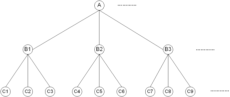
6. Modify the access user parameter associations with the attributes on the LDAP server.
Modify basic information
¡ User Name—Select the user name attribute description used on the LDAP server from the list. UAM uses the value of the attribute as the user name of the LDAP user account when executing the synchronization policy.
¡ Identity Number—Select the identity attribute description used on the LDAP server from the list. UAM uses the value of the attribute as the LDAP user identity when executing the synchronization policy.
¡ Contact Address—Select the contact address attribute description used on the LDAP server from the list, or select Do Not Sync. If you select an attribute, UAM uses the value of the attribute as the user contact address when executing the synchronization policy. If you select Do Not Sync, user contact addresses are not synchronized from the LDAP server.
¡ Telephone—Select the telephone attribute description used on the LDAP server from the list. UAM uses the values of this attribute as the telephone numbers of LDAP users. If you select Do Not Sync, user telephone numbers are not synchronized from the LDAP server.
¡ Email—Select the email attribute description used on the LDAP server from the list. UAM uses the values of this attribute as the email accounts of LDAP users. If you select Do Not Sync, user email accounts are not synchronized from the LDAP server.
¡ User Group—Click the Select User Group icon ![]() . The Select User Group window opens. Select a group and click OK. Available
options include all the user groups
that have been created on IMC
platform. Users synchronized from the LDAP server under this policy are assigned to the selected user group.
. The Select User Group window opens. Select a group and click OK. Available
options include all the user groups
that have been created on IMC
platform. Users synchronized from the LDAP server under this policy are assigned to the selected user group.
Modify additional information
This area is displayed when the additional user information is configured on the IMC platform.
Select an attribute from the list to represent the user additional information entry, or select Do Not Sync. If you select an attribute, UAM uses the value of the attribute to populate the user additional information field when executing the synchronization policy. If you select Do Not Sync, specify the user additional information based on pre-defined rules.
Modify access information
¡ Account Name—The system automatically populates this field with the account name attribute description configured when adding the LDAP server, which cannot be modified.
¡ Expiration Time—Select an attribute
to represent the expiration time of LDAP user account or select Do Not Sync. If you select an attribute, UAM uses the value of the attribute as
the expiration time when executing the synchronization policy. If you select Do Not Sync, enter the expiration time in the format of YYYY-MM-DD or click the Calendar icon ![]() to set the time.
to set the time.
¡ User Password—Select an attribute from the list to represent the user password or select Do Not Sync. If you select an attribute, UAM uses the value of the attribute as the user password when executing the synchronization policy. If you select Do Not Sync, enter a user password in the text box next to the list.
¡ Max. Idle Time (Minutes)—Select an attribute from the list to represent the maximum idle time period a user is allowed to have or select Do Not Sync. If you select an attribute, UAM uses the value of the attribute as the maximum idle time period a user is allowed to have when executing the synchronization policy. If you select Do Not Sync, enter a maximum idle time in the text box next to the list.
¡ Max. Concurrent Logins—Select an attribute from the list to represent the maximum number of concurrent logins allowed with the same user account, or select Do Not Sync. If you select an attribute, UAM uses the value of the attribute as the maximum number of concurrent logins with the same user account when executing the synchronization policy. If you select Do Not Sync, enter the maximum concurrent logins in the text box next to the list.
¡ Login Message—Select an attribute from the list to represent the login message displayed when the users attempt to access the network, or select Do Not Sync. If you select an attribute, UAM uses the value of the attribute as the login message when executing the synchronization policy. If you select Do Not Sync, enter a login message in the text box next to the list.
Modify access device binding information
¡ Device IP—Select an attribute from the list to represent the device IP address, or select Do Not Sync. If you select an attribute, UAM uses the value of the attribute as the device IP address when executing the synchronization policy. If you select Do Not Sync, enter a device IP address in the text box next to the list.
¡ Port—Select an attribute from the list to represent the device port number, or select Do Not Sync. If you select an attribute, UAM uses the value of the attribute as the device port number when executing the synchronization policy. If you select Do Not Sync, enter a device port number in the text box next to the list.
¡ VLAN ID/Inner VLAN ID—Select an attribute from the list to represent the device VLAN ID/Inner VLAN ID, or select Do Not Sync. If you select an attribute, UAM uses the value of the attribute as the device VLAN ID/Inner VLAN ID when executing the synchronization policy. If you select Do Not Sync, enter a device VLAN ID/Inner VLAN ID in the text box next to the list.
¡ Outer VLAN ID—Select an attribute from the list to represent the device outer VLAN ID, or select Do Not Sync. If you select an attribute, UAM uses the value of the attribute as the device outer VLAN ID when executing the synchronization policy. If you select Do Not Sync, enter a device outer VLAN ID in the text box next to the list.
¡ User SSID—Select an attribute from the list to represent the wireless SSID, or select Do Not Sync. If you select an attribute, UAM uses the value of the attribute as the SSID when executing the synchronization policy. If you select Do Not Sync, enter an SSID in the text box next to the list.
¡ Device SN—Select an attribute from the list to represent the device sequence number, or select Do Not Sync. If you select an attribute, UAM uses the value of the attribute as the device sequence number when executing the synchronization policy. If you select Do Not Sync, enter a device sequence number in the text box next to the list.
7. Click Finish.
Modifying a policy with the Sync Object set to Device Users
To modify a policy with the synchronization object set to Device Users:
1. Access the LDAP synchronization policy list page.
2. Click the Modify
icon ![]() for the synchronization policy you want to modify.
for the synchronization policy you want to modify.
The page for modifying synchronization policy opens.
3. Modify the following basic policy information:
¡ Service Group—Displays the service group that the LDAP synchronization policy belongs to. The system automatically populates this field with the same service group as the LDAP server.
¡ Synchronization Priority—Modify the priority of the LDAP synchronization policy. Synchronization policies with higher priority values are executed first in a scheduled synchronization task.
¡ Base DN—Displays the absolute path of the directory that stores user data in the LDAP server. The system automatically populates this field with the base DN specified for the LDAP server.
¡ Sub-Base DN—Enter the absolute path of the subdirectory that stores user data in the LDAP server Make sure that it is in the base DN directory or will be the same as the base DN directory. UAM synchronizes the user data under sub-base DN rather than base DN. The DNs of attributes vary with LDAP servers. To get the correct sub-base DN path, use a tool such as Softerra LDAP Administrator.
¡ Filter Condition—Enter a filter to match user data you want to synchronize to UAM. The default filter is (&(objectclass=*)(cn=*)), which matches entries that have any objectclass attribute value and any cn attribute value. For more information, see "Viewing policy information whose Sync Object is Device Users."
¡ Status—Select Valid or Invalid from the list to enable or disable the policy. Disabling the policy does not affect users that have been synchronized to UAM. They can continue to use the authentication service and self-service.
¡ Sync Options-Auto synchronization—Select this option to execute the policy every day to synchronize all matching users to UAM. The execution time depends on the system settings for scheduled daily tasks. For more information, see "Configuring global system settings."
¡ Sync Options-Create Device User—Select this option to have UAM synchronize from the LDAP server users that do not exist in UAM, and add these users to UAM database as device management users. If you do not select this option, users in LDAP server that do not exist in UAM are not synchronized. To avoid synchronization errors, see "Configure basic policy information:."
¡ Sync Options-Synchronize Users in Current Node Only—Select this option to have UAM synchronize users under the specified sub-base DN, but not synchronize users in any OU under the sub-base DN. If this option is not selected, UAM synchronizes all users in the sub-base DN, including users in the OUs in the sub-base DN.
Other parameters cannot be modified.
4. Click Next. The Modify Device User page opens.
5. Modify the device user parameter associations with the attributes on the LDAP server.
Modify basic information of the device management user
¡ User Name Attribute—Displays the user name attribute that is configured when adding/modifying an LDAP server, which cannot be modified.
¡ Password Attribute—Displays the password attribute that is configured when adding/modifying an LDAP server, which cannot be modified. Each user password in UAM corresponds to a user password in the LDAP server. For more information, see "Supplementary information for LDAP user passwords stored in UAM."
¡ User Password—Select an attribute from the list to represent the local user password, or select Do Not Sync. If you select an attribute, UAM uses the value of the attribute as the local user password when executing the synchronization policy. If you select Do Not Sync, enter a local user password in the text box next to the list. For more information about user passwords, see "Supplementary information for LDAP user passwords stored in UAM."
¡ User Password/Confirm Password—If you select Do Not Sync for the User Password field, enter the same password twice in both fields that is displayed to set it as the local user password stored in UAM.
¡ Login Type—Select a login type for the device management user from the list. Options include Telnet, FTP, SSH, and Terminal.
¡ EXEC Priority—Specify the level of command execution privilege assigned to the device management user. The value range from 0 to 15. A greater value represents a higher privilege, which grants users to execute more commands. If the parameter is not configured, the user uses the default level specified on the device.
Modify the Bound User IP List area
Specify one or more IPv4 address ranges permitted for logins in the list. A device management user can log in to a device only when the IP address of the user is in the list.
To configure the bound user IP list:
a. Click Add in the Bound User IP List area. The page for adding IP address opens.
b. Specify the start and end IP addresses.
Select an attribute from the list to synchronize the IP addresses from the LDAP server. Or select Do Not Sync, and then manually enter the IP addresses. Either way, the end IP address must be greater than the start one.
c. Click OK.
d. Repeat steps a through c to add more IP address ranges.
e. To delete an IP address range, click the Delete icon ![]() next to it. And then click OK in the confirmation dialog
box that opens.
next to it. And then click OK in the confirmation dialog
box that opens.
f. To delete one or more IP address ranges, select the box to the left of the start IP addresses, and click Delete in the Bound User IP List area.
Modify the IP Address List of Managed Devices area
Specify one or more IP address ranges of devices that can be managed. Device management users can only log in the access devices in the list.
g. Click Add in the IP Address List of Managed Devices area. The page for adding devices opens.
h. Specify the start and end IP addresses.
Select an attribute from the list to synchronize the IP addresses from the LDAP server. Or select Do Not Sync, and then manually enter the IP addresses. Either way, the end IP address must be greater than the start one.
i. Click OK.
j. Repeat steps a through c to add more device IP address ranges.
k. To delete a device range, click the Delete icon ![]() of the IP address
range, and click OK in the dialog box that opens.
of the IP address
range, and click OK in the dialog box that opens.
l. To delete one or more device ranges, select the box to the left of the start IP address, and click Delete in the IP Address List of Managed Devices area.
6. Click OK.
Deleting an LDAP synchronization policy
Before you delete a policy, unbind or delete any users that are bound to the synchronization policy you want to delete.
To delete an LDAP synchronization policy:
1. Access the LDAP synchronization policy list page.
2. Click the Delete
icon ![]() for the
synchronization policy you want to delete.
for the
synchronization policy you want to delete.
A confirmation dialog box opens.
Manually executing a synchronization policy
1. Access the LDAP synchronization policy list page.
2. Click the Synchronize link for the policy to start synchronization.
This process may take a few minutes or hours, depending on the amount of user data. When the synchronization stops, UAM displays the synchronization results, including the number of successfully synchronized user accounts and the number of user accounts that failed to be synchronized.
3. (Optional.) To view or save the synchronization failure log, click the Download link.
4. (Optional.) Click Back to return to the synchronization policy list page.
5. (Optional.) Click the Synchronized Result link on the upper right side of the page to view the results of the last synchronization.
Managing users bound to an LDAP synchronization policy
Only the users bound to an LDAP synchronization policy whose Sync Object is set to Access Users can be managed by UAM.
To manage users bound to an LDAP synchronization policy:
1. Access the LDAP synchronization policy list page.
2. Click the Bind User
icon ![]() for the
synchronization policy.
for the
synchronization policy.
The Bind User List displays all LDAP users bound to the policy. For more information about LDAP user management, see "Managing LDAP users."
Validating on-demand synchronization policies
This function allows you to validate all newly added or modified on-demand synchronization policies.
To validate on-demand synchronization policies:
1. Access the LDAP synchronization policy list page.
2. Click On-Demand Sync.
A confirmation dialog box opens.
3. Click OK.
All the on-demand synchronization policies in valid state are validated.
Managing LDAP users
In UAM, an LDAP user is an access user or a device management user that is bound with an LDAP synchronization policy.
During each synchronization process, the following operations are carried out:
· For LDAP users in UAM that exist on the LDAP server, user information in UAM is overwritten by information from the LDAP server.
· For LDAP users in UAM that are removed from the LDAP server, UAM marks the LDAP user status as Nonexistent.
· For users that are newly added to the LDAP server, according to the synchronization policy, the system synchronizes such users to UAM and creates new LDAP users accordingly.
Viewing LDAP users
UAM provides the following methods to view detailed information about LDAP users:
· View LDAP users in the access user list.
· View LDAP users in the all bound user list.
· View LDAP users in the bound user list.
Viewing LDAP users in the access user list
1. Click the User tab.
2. From the navigation tree, select Access User > All Access Users.
The list includes all access users. Account
names with the Bind User icon ![]() are LDAP users.
are LDAP users.
LDAP user information contents
¡ Account Name—Account name of an LDAP user.
¡ User Name—Associated platform user name for an LDAP user.
¡ User Group—Group that the platform user associated with the LDAP user belongs to.
¡ Creation Date—Date when an LDAP user was created.
¡ Validity Time—Date and time when the LDAP user becomes valid. An empty field indicates that the LDAP user is already valid.
¡ Expiration Time—Date and time when an LDAP user expires and becomes invalid. An empty field indicates that the LDAP user never expires.
¡ Account Status—Account status, including Normal, Temporarily Cancelled, and Cancelled.
- Accounts can be authenticated only when they are in the Normal state.
- Temporarily Cancelled indicates an invalid account that is temporarily deleted. Temporarily cancelled accounts are counted in the user accounts managed by a license.
- Cancelled indicates an invalid account that is permanently deleted.
¡ Modify—Click the Modify icon ![]() to display the page for modifying the associated LDAP user.
to display the page for modifying the associated LDAP user.
Viewing LDAP users in the All Bound User List
1. Click the User tab.
2. From the navigation tree, select Access User > LDAP User.
The list includes all LDAP users.
All Bound User List contents
¡ Account Name—Account name of an LDAP user.
¡ User Name—Platform user name that the LDAP user is associated with.
¡ User Group—Group that an LDAP user belongs to.
¡ Policy Name—Name of the LDAP synchronization policy an LDAP user is bound with. Click the name link of a policy to display the Sync Policy Information page.
For more information, see "Viewing LDAP synchronization policy details."
¡ Status in LDAP Server—Status of an LDAP user during the last synchronization process: Existent or Nonexistent.
If the user is in the LDAP server, the field displays Existent. Otherwise, the field displays Nonexistent.
To learn the current status of an LDAP user, synchronize the user immediately. For specific procedures, see "Manually executing a synchronization policy."
Viewing LDAP users in the Bound User List
1. Click the User tab.
2. From the navigation tree, select Access User > LDAP User > Sync policy name.
The list includes all LDAP users bound with the policy.
Bound Users List contents
¡ Account Name—Account name of the LDAP user.
¡ User Name—Associated platform user name for the LDAP user.
¡ User Group—User group to which the LDAP user belongs.
¡ Policy Name—Name of the synchronization policy bound to the LDAP user. Click the policy name to view the policy details. For more information, see "Viewing LDAP synchronization policy details."
¡ Status in LDAP Server—Status of the LDAP user in the LDAP server during last synchronization: Existent or Nonexistent.
To learn the current status of an LDAP user, synchronize the user immediately. For specific procedures, see "Manually executing a synchronization policy."
Querying LDAP users
You can use the same procedure to query LDAP users in the All Bound User List and the Bound User List. This example uses the All Bound User List.
To query LDAP users in the All Bound User List:
1. Click the User tab.
2. From the navigation tree, select Access User > LDAP User.
The list includes all the LDAP users.
3. Specify one or more of the following query criteria:
¡ Account Name—Enter a partial or complete account name of an LDAP user. For example, if you enter x, all account names that contain x are matched.
¡ User Group—Click the Select User Group icon ![]() . The Select User Group window opens. Select a group and click OK. You can select only one user group for query.
. The Select User Group window opens. Select a group and click OK. You can select only one user group for query.
¡ Service Name—Select an existing service from the list.
¡ Status in LDAP Server—Select the LDAP user status from the list. Options include Unknown, Existent, and Nonexistent. To learn the current status of the LDAP user, synchronize the user immediately. For more information, see "Synchronizing LDAP users."
The query ignores empty fields.
The list includes all LDAP users matching the query criteria.
To clear the query criteria, click Reset. The All Bound User List includes all LDAP users.
Viewing LDAP user details
You can use the same procedure to view LDAP user details in the Access User List, the All Bound User List, and the Bound User List of a specific synchronization policy. This example uses the All Bound User List.
To view LDAP user details in the All Bound User List:
1. Click the User tab.
2. From the navigation tree, select Access User > LDAP User.
The list includes all the LDAP users.
3. Click the account name of an access user to display the Access Account Info page.
The page includes the following areas and parameters:
Basic Information
¡ User Name—Platform user name used on the LDAP server.
¡ ID Number—Platform user's identity number used on the LDAP server.
¡ Contact Address—Platform user's contact address used on the LDAP server.
¡ Telephone—Platform user's telephone number used on the LDAP server.
¡ Email—Platform user's email address used on the LDAP server.
¡ User Group—User group to which the LDAP user belongs. If the user group has a parent group or subgroups, this field displays the complete group hierarchy of the user group.
Access Information
¡ Account Name—Account name of an LDAP user. When an LDAP user is blacklisted, the account name of the user is followed with Blacklisted Users.
¡ Account Status—Options are Normal, Temporarily Cancelled, or Cancelled. Except the normal state, accounts in any other state cannot be authenticated.
- Accounts can be authenticated only when they are in the Normal state.
- Temporarily Cancelled indicates an invalid account that is temporarily deleted. Temporarily cancelled accounts are counted in the user accounts managed by a license.
- Cancelled indicates an invalid account that is permanently deleted.
¡ Creation Date—Date when the LDAP user was created.
¡ Validity Time—Date and time when the LDAP user becomes valid. An empty field indicates that the LDAP user is already valid.
¡ Expiration Time—Date and time when the LDAP user expires and becomes invalid. An empty field indicates that the LDAP user never expires.
¡ Max. Idle Time (Minutes)—The maximum idle time that the LDAP user is allowed to have. The LDAP user is forced to log off when the idle time expires.
An empty field indicates that the LDAP user can always stay online.
¡ Max. Concurrent Logins—The maximum number of concurrent logins allowed by the user account.
An empty field indicates that maximum number of the concurrent logins of the LDAP user is not restricted.
¡ Online Status—Whether or not the LDAP user is online.
¡ Last Logoff—Time when the LDAP user last logged off.
¡ Login Message—Message delivered to the LDAP user when the user passes the authentication.
¡ Guest Manager Type—Whether or not the LDAP user is a Guest Manager or Super Guest Manager. This parameter is displayed only after the LDAP user is specified as a Guest Manager.
Access Service list contents
The list includes all services available for the users.
¡ Service Name—Name of the service.
¡ Service Suffix—Distinguishes services when LDAP users perform authentication. The user name and service suffix entered by the LDAP user is closely related to the authentication domain. For more information, see Table 30.
¡ Allocate IP—IP address that the access service allocates to the user. An empty field indicates that the access service does not allocate any IP address.
Smart Device MAC Address Binding area
The Smart Device MAC Address Binding area displays all smart device MAC addresses that are bound to the account for transparent authentication (see "Configuring transparent portal authentication").
¡ Service Name/MAC Address—Displays the service name and MAC address that are bound to the account for transparent portal authentication.
¡ Transparent Authentication—Whether the MAC address is allowed to use the account and service for transparent portal authentication. The status can be Enabled or Disabled.
¡ Enabled/Disabled Time—If transparent portal authentication is enabled, this field indicates the time when the device MAC address was bound to the user and service. If transparent portal authentication is disabled, this field indicates the time when transparent authentication was automatically or manually disabled on the device.
Access Device Binding Information area
To pass authentication, an LDAP user must meet all requirements of the access device bindings and terminal bindings. The query ignores empty fields.
¡ Device SN—Sequence number of the access device bound to the LDAP user. An LDAP user can pass authentication only when sequence number of the access device matches this parameter value.
¡ Port—Port of the access device bound to the LDAP user. An LDAP user can pass the authentication only when the connected port (of any access device) matches the bound port. UAM uses the last portion of an interface number to match access ports. For example, if you specify port 3, both interface number 1/0/3 and interface number 2/0/3 match the port.
¡ Outer VLAN ID—Outer VLAN ID bound to the LDAP user. An LDAP user can pass the authentication only when the VLAN tag of the packets sent by the user matches the bound outer VLAN tag.
¡ VLAN ID/Inner VLAN ID—VLAN ID or inner VLAN ID bound to the LDAP user. A user can pass the authentication only when the VLAN tag of the packets sent by the user matches the bound VLAN tag.
¡ User SSID—SSID bound to the LDAP user when the user uses wireless access. An LDAP user can pass authentication only when the used SSID is on the User SSID list.
¡ Device IP—IPv4 address of the access device bound to the LDAP user. An LDAP user can pass authentication only when the connected access device's IP address is on the Device IP list. The access device IPv4 address is the address when the device is being added to UAM as an access device.
¡ Device IPv6 Address—IPv6 address of the access device bound to the LDAP user. An LDAP user can pass authentication only when the connected access device's IP address is on the Device IPv6 Address list. The access device IPv6 address is the address when the device is being added to UAM as an access device.
Terminal Binding Information area
To pass authentication, the LDAP user must meet all requirements of the access device bindings and terminal bindings. The query ignores empty fields.
¡ Computer Name—Name of the computer bound to the LDAP user. An LDAP user can pass authentication only when the computer name matches the bound computer name.
¡ IMSI—IMSI number bound to the LDAP user. An LDAP user can pass authentication only when the IMSI number of the user endpoint matches the bound IMSI.
¡ Windows Domain—Name of the Windows domain bound to the LDAP user. An LDAP user can pass authentication only when the computer used by the user joins or logs in to the domain.
¡ Terminal IP Address—List of IPv4 addresses or IPv4 address ranges bound to the LDAP user. An LDAP user can pass authentication only by using an endpoint with a bound IPv4 address or an IPv4 address in the bound IPv4 address ranges.
¡ Terminal MAC Address—List of MAC addresses bound to the LDAP user. An LDAP user can pass authentication only by using an endpoint with a bound MAC address or a MAC address in the bound MAC address ranges.
¡ Terminal IPv6 Address—List of IPv6 addresses bound to the LDAP user. An LDAP user can pass authentication only by using an endpoint with a bound IPv6 address or an IPv6 address in the bound IPv4 address ranges.
¡ IMEI—IMEI number bound to the LDAP user. An LDAP user can pass authentication only when the IMEI number of the user endpoint matches the bound IMEI.
Action
The Action menu is located to the right of the Access Account Info pane, and offers the following options:
¡ Refresh—Click the link to refresh the detailed information about the access user.
¡ Modify—Click the link to access the page for modifying the access user. For more information, see "Modifying LDAP user information."
¡ Cancel Account—Click the Cancel Account link and click OK in the confirmation dialog box to delete the access user.
¡ Add to Blacklist—Available only when the access user is not blacklisted. Click the Add to Blacklist link and click OK in the dialog box to add the access user to the blacklist.
¡ Release from Blacklist—Available only when the access user is blacklisted. Click the link and click OK in the dialog box to release the access user from the blacklist.
¡ Authentication Failure Log—Click the link to view the list of authentication failure logs for the access user. For more information, see "Managing authentication failure logs."
¡ Authentication Violation Log—Click the link to view the list of authentication violation logs for the access user. For more information about violation logs, see "Managing authentication violation logs."
¡ Access Details—Click the link to view the list of access details for the access user. For more information, see "Viewing ordinary access user details."
¡ MAC Address Entry—Click the link to view the list of MAC addresses bound to the LDAP user. These addresses are used for transparent MAC authentication. This link is displayed only when the transparent MAC authentication function is enabled in user endpoint settings. For information about transparent MAC authentication, see "Transparent MAC authentication."
¡ Unbind LDAP User—Click the link to unbind the LDAP user with the LDAP synchronization policy. The LDAP user becomes a common access user after this process.
¡ Basic User Info—Click the link to access the page that displays detailed information about the platform user to which the access user is attached. For more information, see HPE Intelligent Management Center v7.3 Enterprise and Standard Platform Administrator Guide.
¡ Send Password via SMS—Click the link to send a message that contains the account name and password to the current user. To use this function, operators must first enable Send Password via SMS in the IMC platform. For more information, see HPE Intelligent Management Center v7.3 Enterprise and Standard Platform Administrator Guide. UAM cannot read user passwords from some LDAP servers (Microsoft ADs, for example), and you cannot send password messages to users synchronized from such LDAP servers.
¡ Temporary Cancel—This link is displayed only when the LDAP user account is in Normal state. Click the link to display a confirmation dialog box. Click OK to temporarily cancel the user account.
¡ Undo TempCancel—This link is displayed only when the LDAP user account is in Temporarily Cancelled state. Click the link to display a confirmation dialog box. Click OK to restore the user account to the normal state.
Binding common users with LDAP synchronization policies
UAM provides the following ways to bind users with an LDAP synchronization policy:
· Auto—UAM automatically synchronizes user data from an LDAP server and creates corresponding LDAP users during synchronization.
These users are automatically bound with the synchronization policy. For more information, see "Manually executing a synchronization policy."
· Manual—A common user can be manually bound with a synchronization policy.
To manually bind access users with an LDAP synchronization policy:
1. Click the User tab.
2. From the navigation tree, select Access User > LDAP User > Policy Name.
The list includes all LDAP users bound with the policy.
3. Click Bind in the bound user list area.
The Unbound User List window opens, displaying all the access users that are not bound with any LDAP synchronization policy.
4. Specify one or more of the following query criteria in the Query Unbound Users area:
¡ Account Name—Enter a partial or complete account name of an access user. For example, if you enter x, all account names that contain x are matched.
¡ User Group—Click the Select User Group icon ![]() . The Select User Group window opens. Select a group and click OK. You can select only one user group for query.
. The Select User Group window opens. Select a group and click OK. You can select only one user group for query.
The query ignores empty fields.
5. Click Query.
The list includes all unbound users that match the query criteria.
6. Select one or more users.
7. Click OK.
The selected users are displayed in the bound users list with the Status in the LDAP Server of Unknown.
8. Click Sync All in the Bound User List area to start executing the synchronization policy.
This process may take a few minutes or hours, depending on the amount of user data.
After synchronization, if a newly bound LDAP user exists in the LDAP server, the user status in the LDAP server is changed to Existent. Otherwise, the user status in the LDAP server is changed to Nonexistent.
Unbinding LDAP users with an LDAP synchronization policy
To unbind LDAP users with an LDAP synchronization policy:
1. Click the User tab.
2. From the navigation tree, select Access User > LDAP User > Policy Name.
The list includes all LDAP users bound with the synchronization policy.
3. Select one or more users to be unbound from the policy.
4. Click Unbind in the Bind Users List area.
A confirmation dialog box opens.
An LDAP user becomes a common access user after being unbound with the LDAP synchronization policy.
Synchronizing LDAP users
A synchronization operation synchronizes all users bound with a synchronization policy under the following guidelines:
· For LDAP users in UAM that exist on the LDAP server, user information in UAM is overwritten by that stored on the LDAP server.
· For LDAP users in UAM that no longer exist on the LDAP server, UAM marks the LDAP user status as Nonexistent.
· For users that are newly added to the LDAP server, according to the synchronization policy, the system synchronizes such users to UAM and creates new LDAP users accordingly.
To synchronize LDAP users:
1. Click the User tab.
2. From the navigation tree, select Access User > LDAP User > Policy Name.
The list includes all LDAP users bound with the policy.
3. Click Sync All in the Bound User List area to start executing the synchronization policy.
This process may take a few minutes or hours, depending on the amount of user data.
When the synchronization stops, UAM displays the synchronization results, including the number of successfully synchronized user accounts and the number of user accounts that failed to be synchronized.
4. (Optional.) To view or save the synchronization failure log, click the Download link.
5. (Optional.) Click Back to return to Bound Users List.
Modifying LDAP user information
Modifications to a user parameter synchronized from an LDAP server will last only until the next synchronization, because during synchronization the user information in UAM is overwritten by the information stored on the LDAP server.
To modify LDAP user information:
1. Click the User tab.
2. From the navigation tree, select Access User > All Access Users.
The list includes all access users. Account names with the Bind User icon ![]() are LDAP users.
are LDAP users.
3. Click the Modify
icon ![]() for the LDAP user
you want to modify.
for the LDAP user
you want to modify.
The page for modifying the LDAP user opens.
Modify access information
¡ Validity Time—Click the Calendar icon ![]() to select a valid time, or enter a valid time in the
format of YYYY-MM-DD hh:mm. The LDAP user becomes valid since the valid time. An empty field indicates that the LDAP user becomes valid immediately after the modification.
to select a valid time, or enter a valid time in the
format of YYYY-MM-DD hh:mm. The LDAP user becomes valid since the valid time. An empty field indicates that the LDAP user becomes valid immediately after the modification.
¡ Expiration Time—Click the Calendar icon ![]() to set the expiration time, or enter a time string in the format of YYYY-MM-DD hh:mm. The
LDAP user becomes invalid since the expiration time. An empty field indicates that the LDAP user never expires.
to set the expiration time, or enter a time string in the format of YYYY-MM-DD hh:mm. The
LDAP user becomes invalid since the expiration time. An empty field indicates that the LDAP user never expires.
¡ Max. Idle Time (Minutes)—Enter the maximum idle time allowed for the LDAP user. The LDAP user is forced to log off when the idle time expires. An empty field indicates that the LDAP user can always stay online.
¡ Max. Concurrent Logins—Enter the maximum number of concurrent logins allowed for the LDAP user. An empty field indicates that the maximum number of concurrent logins with the same user account is not restricted.
¡ Login Message—Enter the message delivered to the LDAP user when the user passes authentication.
Other parameters cannot be modified.
Modify access service
If Apply for Service by User Group is disabled, UAM displays this field to allow manual service assignment for LDAP users. If Apply for Service by User Group is enabled, UAM hides this field and automatically applies for services for LDAP users according to their user groups. For more information about configuring the Apply for Service by User Group option, see "Configuring global system settings."
The access service list displays all services available to users. You may select multiple services with different suffixes. To select a service, click the box next to it.
¡ Service Name—Unique name of the service in UAM.
¡ Service Suffix—Distinguishes services when endpoint users perform authentication. The user name and service suffix entered by the endpoint user is closely related to the authentication domain. For more information, see Table 30.
¡ Status—Identifies whether the service is available. The access service list displays all services available to users, including those with their status changed to Unavailable by network administrators.
¡ Allocate IP—Enter the IP address that the access service allocates to the user. An empty field indicates that the access service does not allocate any IP address.
Modify access device binding information
Set the values for access device binding parameters. The binding parameters in this area take effect only when they are selected in the Authentication Binding Information area of the selected services. For example, the Device IP parameter is effective to the services only with the Bind Access Device IP option selected.
If you select a binding option for a service but do not specify any value for the parameter in the access device binding information, UAM automatically learns the binding information for the service when the user first passes authentication.
To pass authentication, the LDAP user must meet all requirements of the access device bindings and terminal bindings.
¡ Device SN—Enter the sequence number of the access device bound to the LDAP user. An LDAP user can pass authentication only when the sequence number of the access device matches this parameter value.
¡ Port—Enter the port number of the access device to which an LDAP user is bound. A user can pass the authentication only when connected port (of any access device) matches the bound port. UAM uses the last portion of an interface number to match access ports. For example, if you specify port 3, both interface number 1/0/3 and interface number 2/0/3 match the port.
¡ Outer VLAN ID—Enter the outer VLAN ID bound to the LDAP user. An LDAP user can pass the authentication only when the VLAN tag of the packets sent by the user matches the bound outer VLAN tag.
¡ VLAN ID/Inner VLAN ID—Enter the VLAN ID or inner VLAN ID bound to the LDAP user. An LDAP user can pass the authentication only when the VLAN tag of the packets sent by the user matches the bound VLAN tag.
¡ User SSID—Enter the SSID bound to the LDAP user when the user uses wireless access. An LDAP user can pass authentication only when the used SSID is on the User SSID list.
¡ Device IP—IPv4 address of the access device bound to the LDAP user. An LDAP user can pass authentication only when the connected access device's IP address is on the Device IP list. The access device IPv4 address is the address when the device is being added to UAM as an access device.
¡ Device IPv6 Address—IPv6 address of the access device bound to the LDAP user. An LDAP user can pass authentication only when the connected access device's IP address is on the Device IPv6 Address list. The access device IPv6 address is the address when the device is being added to UAM as an access device.
Modify terminal binding information
Set the values for terminal binding parameters. The binding parameters in this area take effect only when they are selected in the Authentication Binding Information area of the selected services. For example, the Computer Name parameter is effective to the services only when the Bind Computer Name option is selected.
If you select a binding option for a service but do not specify any value for the parameter in the terminal binding information, UAM automatically acquires the binding information for the service when the user first passes authentication.
To pass authentication, the LDAP user must meet all requirements of the listed access device bindings and terminal bindings.
¡ Computer Name—Enter the name of the computer bound to the LDAP user. An LDAP user can pass the authentication only when the computer name of the user matches the bound computer name.
¡ IMSI—Enter the IMSI number bound to the LDAP user. An LDAP user can pass the authentication only when the IMSI of the endpoint matches the bound IMSI.
¡ Windows Domain—Enter the name of the Windows domain name bound to the LDAP user. A user can pass authentication only after the computer joins or logs in to domain.
¡ Terminal IP Address—Enter a list of IPv4 addresses or IPv4 address ranges bound to the LDAP user. An LDAP user can pass authentication only by using an endpoint with a bound IPv4 address or an IPv4 address in the bound IPv4 address ranges.
¡ Terminal MAC Address—Enter a list of MAC addresses bound to the LDAP user. An LDAP user can pass authentication only by using an endpoint with a bound MAC address.
¡ Terminal IPv6 Address—Enter a list of IPv6 addresses bound to the LDAP user. An LDAP user can pass authentication only by using an endpoint with a bound IPv6 address.
¡ IMEI—Enter the IMEI number bound to the LDAP user. An LDAP user can pass the authentication only when the IMEI of the endpoint matches the bound IMEI.
Deleting LDAP users
1. Click the User tab.
2. From the navigation tree, select Access User > All Access Users.
The list includes all access users. Account names with the Bind User icon ![]() are LDAP users.
are LDAP users.
3. Select one or more LDAP users you want to delete.
4. Click Cancel Account.
The Cancel Accounts page contains a Delete Platform Users option.
¡ If the Delete Platform Users option is not selected, UAM deletes the selected access users only.
¡ If the Delete Platform Users option is selected, UAM deletes the selected access user and the platform user to which the access user is attached, provided the platform user does not have any other access user account. If the associated platform user has other access user accounts, UAM deletes the selected access user only.
Adding an LDAP user to the blacklist
A blacklisted user cannot pass authentication for network access.
You can add an LDAP user to the blacklist from either the access user list page or the access user details page.
Adding LDAP users to the blacklist on the access user list page
1. Click the User tab.
2. From the navigation tree, select Access User > All Access Users.
The list includes all access users. Account names with the Bind User icon ![]() are LDAP users.
are LDAP users.
3. Select one or more LDAP users you want to add to the blacklist.
4. Click Add to Blacklist.
A confirmation dialog box opens.
5. Click OK.
Adding an LDAP user to the blacklist on the Access User Info page
The following example accesses the Access Account Info page from the All Bound User List. The page can also be accessed from the access user list or the bound user list.
To add an LDAP user to the blacklist:
6. Click the User tab.
7. From the navigation tree, select Access User > LDAP User.
The list includes all the LDAP users.
8. Click the account name of an access user.
The Access Account Info page opens.
9. Click Add to Blacklist in the Action menu.
A confirmation dialog box opens.
10. Click OK.
Releasing an LDAP user from the blacklist
After a blacklisted user has been released from the blacklist, the user is no longer blacklisted and can pass authentication for network access.
You can release an LDAP user from the blacklist using the Access Account Info page. The following example accesses the Access Account Info page from the All Bound User List. The page can also be accessed from the access user list or the bound user list.
To release an LDAP user from the blacklist:
1. Click the User tab.
2. From the navigation tree, select Access User > LDAP User.
The list includes all LDAP users.
3. Click the account name of a blacklisted LDAP user.
4. Click Remove from Blacklist in the Action menu.
A confirmation dialog box opens.
5. Click OK.
Applying for services for LDAP users
If the system parameter Apply for Service by User Group is enabled, UAM automatically applies for each LDAP user the services assigned to their respective user groups.
If Apply for Service by User Group is disabled, operators can manually apply for services for LDAP users.
For more information about the Apply for Service by User Group option, see "Configuring global system settings."
To manually apply services for LDAP users:
1. Click the User tab.
2. From the navigation tree, select Access User > All Access Users.
The list includes all access users. Account names with the Bind User icon ![]() are LDAP users.
are LDAP users.
3. Select one or more LDAP users.
4. Click Apply for Service. The page for bulk applying for services for LDAP users opens.
For subsequent operation steps, see "Querying and maintaining accounts in batches."
Canceling services for LDAP users
If the system parameter Apply for Service by User Group is enabled, UAM automatically applies for each LDAP user the services assigned to their respective user groups.
If Apply for Service by User Group is disabled, operators can manually apply for services for LDAP users.
For more information about the Apply for Service by User Group option, see "Configuring global system settings."
To manually cancel services for LDAP users:
1. Click the User tab.
2. From the navigation tree, select Access User > All Access Users.
The list includes all access users. Account names with the Bind User icon ![]() are
LDAP users.
are
LDAP users.
3. Select the service to be cancelled from the Service Name list in the query area.
4. Select one or more LDAP users.
5. Click Cancel Service.
A confirmation dialog box opens.
Exporting LDAP users
In some cases, an LDAP synchronization policy may fail to synchronize users as precisely as required. This causes synchronization of redundant user information, and wastes user licenses.
To address this problem, you can use the following method, which allows you to filter the users to be synchronized:
1. Use the user export function to export user data on the LDAP server to a text file.
2. Edit the text file to remove the unnecessary user information.
3. Use the batch user import function to import the text file to UAM. For more information, see "Importing accounts in batches."
4. Create a synchronization policy, and clear the Synchronize New Users and Accounts and Synchronize New Accounts of Existing Users options in the policy.
For more information, see "Adding an LDAP synchronization policy."
5. Bind the imported users with the synchronization policy created in the previous step.
For more information, see "Binding common users with LDAP synchronization policies."
These above operations allow you to synchronize only the filtered users when executing a synchronization policy.
To export LDAP users:
6. Click the User tab.
7. From the navigation tree, select User Access Policy > LDAP Service > User Export.
The page for querying user attributes opens.
8. Configure the user attribute query criteria, including:
¡ LDAP Server—Select an LDAP server from the list. Available options include any LDAP servers configured in UAM.
¡ Base DN—Displays the absolute path of the directory that stores user data in the LDAP server.
¡ Sub-Base DN—Enter the absolute path of the subdirectory that stores user data in the LDAP server and make sure that it is in the base DN directory or is the same as the base DN directory. UAM synchronizes the user data under sub-base DN rather than base DN.
The DNs of attributes vary with LDAP servers. To get the correct sub-base DN path, use a tool such as Softerra LDAP Administrator.
¡ Filter Condition—Enter a filter to match user data you want to synchronize to UAM. The default filter is (&(objectclass=*)(cn=*)), which matches entries that have any objectclass attribute value and any cn attribute value. For information about defining a filter, see "Adding a policy when the Service Sync Type is Manual Assignment."
9. Click Query to display the window for selecting user attributes, including:
¡ Attribute Name—Displays all the attributes that can be exported. Select the attributes to be exported.
¡ Sample—Sample values for the corresponding attribute.
¡ Separator—Exported user data is stored in columns in the text file. Each column corresponds to an attribute. Select the separator between columns. Available options include Space, TAB, comma (,), colon (:), pound sign (#), and dollar sign ($).
¡ Export Column Header—Specifies whether to export the attribute names as column titles in the text file. If you do not select this option, the text file has no column titles.
10. Click Export.
11. Click Download the Export File to display the exported user data.
12. Click Back to return to the Query User Attributes page.
Batch LDAP user operations
Batch operations for LDAP users are identical to those for common access users. For more information, see "Batch operations."
Supplementary information for LDAP user passwords stored in UAM
Operators can synchronize user data from LDAP server to UAM as access users or device management users. Such users have two passwords in UAM: an LDAP user password and a local user password.
· LDAP user password—During synchronization, UAM reads the values of the Password Attribute from the LDAP server as the LDAP user passwords. If the value cannot be read, the LDAP user password field stays empty. The Password Attribute is configured when adding or modifying LDAP servers.
· Local user password—In a synchronization policy, if you synchronize the values of User Password from a certain attribute on the LDAP server, UAM reads the values of this attribute as the local user passwords. If you select Do Not Sync for the User Password field and have manually configured a password, UAM uses this password as the local password for the user.
When an access user or device management user bound with a synchronization policy initiates an authentication request, UAM checks the password provided by the endpoint user against the LDAP user password. If the field for LDAP user password is empty, UAM forwards the password to the LDAP server, where the password is checked against the value of the associated Password Attribute.
When an access user or device management user that is unbound from its LDAP server initiates an authentication request, UAM checks the password provided by the endpoint user against the local user password.
Configuring LDAP parameters
1. Click the User tab.
2. From the navigation tree, select User Access Policy > LDAP Service > LDAP Parameters.
3. On the LDAP Parameters page, configure the following parameters:
¡ Delete Nonexistent LDAP Users in Synchronization—Select Enable to delete users that have been deleted from the LDAP server during synchronization. Select Disable to keep the users that have been deleted from the LDAP server.
¡ LDAP User Move between Servers—Select Enable to allow synchronized LDAP users to move between LDAP servers. Select Disable to disable the function.
Enable the function to permit data transfer of employees between LDAP servers on an enterprise network to meet job reallocation requirements. UAM moves an existing LDAP user to the LDAP server during a synchronization only when one of the following conditions is met:
- The LDAP server no longer includes the DN specified by the policy of the last synchronization.
- On the LDAP server, the user has been moved to the DN specified by the policy for the current synchronization.
- The policy for the current synchronization has the same priority as or a higher priority than the policy for the last synchronization.
¡ LDAP Paging—Select this option to break the LDAP user query results into pages and specify the maximum number of LDAP users a page can display. If the LDAP server does not support paged results, do not select this option.
¡ LDAP On-Demand Authentication Mode—Select a mode for on-demand authentication of LDAP users. In on-demand authentication, UAM periodically backs up LDAP user information to a temporary table. When a user passes authentication on an LDAP server, UAM creates an LDAP user account for the user with information synchronized from the LDAP server.
- Local Backup—UAM forwards authentication requests only for LDAP users that exist in the temporary table. This mode applies to scenarios where multiple on-demand synchronization policies are used.
- Realtime Authentication—UAM forwards authentication requests for all LDAP users, even if they do not exist in the temporary table. This mode enables realtime authentication of new users immediately after they are added to the LDAP server. This mode is resource-consuming. Use this mode when UAM has only a few on-demand synchronization policies. To use this mode, make sure both the user group and service synchronization parameters are manually specified for the LDAP server.
¡ MSCHAPv2 Server Log Level—Select a log level from the list. Options are Fatal, Error, Warning, Info, Debugging, and Trace. Use the default level Warning when the system operation is correct. Use Trace only for fault location.
¡ Bypass Authentication for LDAP Server Failure—Select Enable to allow LDAP users to pass authentication and access the network when the LDAP server is unavailable. Select Disable to prohibit LDAP users from passing authentication and accessing the network when the LDAP server is unavailable.
¡ LDAP Sync/Backup Task—Specify the interval and time point to synchronize or back up LDAP users to UAM. The interval is an integer in the range of 1 to 365. The time point is an integer in the range of 0 to 23. To specify continuous hours, enter a string in the format X-Y. Use a comma to separate multiple time points. For example, if 3 days 9, 14-16 is set in this field, UAM executes synchronization at 9:00, and the beginning of every hour of 14:00 through 16:00 every 3 days.
- Sync—UAM synchronizes complete information about LDAP users to UAM and implement regular authentication on the synchronized users. The user data is displayed in the access user list.
- Backup—UAM backs up partial information about LDAP users, including user names and DNs, to a temporary table for on-demand authentication. The user data does not appear in the access user list.
¡ Next LDAP Sync/Backup Time—This field is automatically populated with the next synchronization or backup time when you configure the LDAP Sync/Backup Task parameter.
¡ Enable LDAP Incremental Sync/Backup Task—Select this option to back up users who have been added or modified since the last synchronization. The task is performed at specified intervals for all LDAP on-demand sync policies. The value of the interval must be a multiple of 5 in the range of 5 to 60, in minutes. For other LDAP sync policies, UAM first performs full synchronization, and then performs incremental synchronization. For example, set the LDAP Sync/Backup Task field to 3-11. UAM will perform full synchronization at 3:00, and then perform incremental synchronization at the beginning of every hour of 4:00 through 11:00.
¡ Microsoft AD Incremental Condition—Select a filter in the incremental LDAP syntax query for incremental synchronization or backup. The default filter for Microsoft AD is whenChanged. This parameter is available only when the Enable LDAP Incremental Sync/Backup Task option is selected.
¡ Microsoft AD Format—Select a time format for the incremental condition. The default format for Microsoft AD is yyyyMMddHHmmss.sss. This parameter is available only when the Enable LDAP Incremental Sync/Backup Task option is selected.
¡ General Incremental Condition—Select a filter in the incremental LDAP syntax query for incremental synchronization or backup. The default filter for general LDAP server is whenChanged. This parameter is available only when the Enable LDAP Incremental Sync/Backup Task option is selected.
¡ General Format—Select a time format for the incremental condition. The default format for general LDAP server is yyyyMMddHHmmss.sss. This parameter is available only when the Enable LDAP Incremental Sync/Backup Task option is selected.
4. Modify the password of the virtual computer on the domain controller:
a. Click the link next to The script to modify the computer password and download the ModifyComputerAccountPass.vb script.
b. Open the script with a text editor and edit the following content:
- In the CN=testAccount,CN=Computers,DC=CONTOSO,DC=COM string, replace testAccount with the virtual computer name, and modify CONTOSO and COM according to the domain name of the computer. For example, if the domain name is H3C.COM, replace DC=CONTOSO,DC=COM with DC=H3C,DC=COM.
- Replace iMC123 with the virtual computer password.
c. Copy the script to the domain controller.
d. In the command window of the domain controller, enter the folder where the script is saved and execute cscript ModifyComputerAccountPass.vbs.
5. Click OK.
Configuring certificate authentication
Certificate authentication is an advanced security authentication method. It authenticates users by using a certificate rather than user names and passwords.
UAM certificate authentication supports 802.1X access, portal access, and local authentication. However, it does not support VPN or MAC address access, transparent, RSA, or roaming authentication. Some of the certificate authentication methods support LDAP authentication.
Implementing local certificate authentication for 802.1X or portal users
1. Configure UAM:
a. Manage the root certificate, server certificate, and certificate revocation list (CRL) in UAM.
The CRL records revoked certificates. For more information, see "Managing root certificate, server certificate, and CRL in UAM."
b. Add an access condition, access policy, or service.
An access condition and service can be added regardless of whether certificate authentication is configured. For more information, see "Configuring access services."
c. Add an access policy.
When adding an access policy, select a preferred EAP type and a subtype. Certificate-based EAP authentication types include EAP-TLS, EAP-TTLS, and EAP-PEAP. EAP-TTLS and EAP-PEAP include EAP-MD5, EAP-GTC, and EAP-MSCHAPv2.
EAP-PEAP and EAP-MD5 are H3C proprietary EAP types and are used for LDAP authentication exclusively. When you use EAP-PEAP and EAP-MD5, iNode clients and UAM must cooperate with an LDAP server to implement LDAP authentication.
d. Add an access device.
For more information about access device configuration, see "Configuring access devices."
e. Add an access user.
The supported authentication certificate types and subtypes vary by access users, as described in Table 32. For more information about access user configuration, see "Managing access users."
Table 32 Authentication certificate types and subtypes supported by different access users
|
Access user type |
Supported authentication certificate types and subtypes |
|
Common access user |
· EAP-TLS · EAP-TTLS/EAP-MD5 · EAP-TTLS/EAP-MSCHAPv2 · EAP-TTLS/EAP-GTC · EAP-TTLS/PAP · EAP-TTLS/MSCHAPv2 · EAP-PEAP/EAP-MSCHAPv2 · EAP-PEAP/EAP-MD5 · EAP-PEAP/EAP-GTC |
|
Guest |
· EAP-TLS · EAP-TTLS/EAP-MD5 · EAP-TTLS/EAP-MSCHAPv2 · EAP-TTLS/EAP-GTC · EAP-TTLS/PAP · EAP-TTLS/MSCHAPv2 · EAP-PEAP/EAP-MSCHAPv2 · EAP-PEAP/EAP-MD5 · EAP-PEAP/EAP-GTC |
|
User synchronized from Windows AD |
· EAP-TLS · EAP-PEAP/EAP-MSCHAPv2 · EAP-PEAP/EAP-MD5 · EAP-PEAP/EAP-GTC |
|
User synchronized from OpenLDAP (with a plaintext password) |
· EAP-TLS · EAP-TTLS/EAP-MD5 · EAP-TTLS/EAP-MSCHAPv2 · EAP-TTLS/EAP-GTC · EAP-TTLS/PAP · EAP-TTLS/MSCHAPv2 · EAP-PEAP/EAP-MSCHAPv2 · EAP-PEAP/EAP-MD5 · EAP-PEAP/EAP-GTC |
|
User synchronized from OpenLDAP (with a ciphertext password) |
· EAP-TTLS/EAP-MD5 · EAP-TTLS/EAP-GTC · EAP-TTLS/PAP · EAP-PEAP/EAP-MD5 · EAP-PEAP/EAP-GTC |
|
Mute terminal user |
Does not support certificate authentication. |
2. Configure the access device.
¡ 802.1X access uses an EAP relay agent. For more information about configuring 802.1X access and RADIUS authentication on the access device, see the configuration guide of the access device.
¡ Portal access requires the access device to support EAP authentication. Only HP Comware and H3C devices meet this requirement. For information about configuring portal access and RADIUS authentication on the access device, see the configuration guide of the access device.
3. Import the root certificate and client certificate to the user endpoint.
For information about installing client certificates on a PC, see the video configuration example Certificate-Based 802.1X Authentication.
4. Create an 802.1X or portal authentication connection in the iNode client of the user endpoint.
a. Select Enable advanced authentication and Certificate Authentication.
Figure 103 Selecting certificate authentication for an 802.1X connection
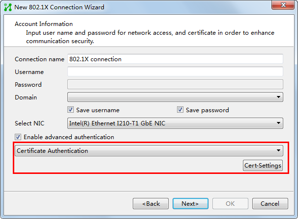
Figure 104 Selecting certificate authentication for a portal connection
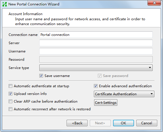
b. Click Cert-Settings.
The Cert-Settings window opens.
Figure 105 Configuring certificate authentication
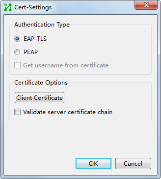
c. Select an authentication type, which must be the same as that configured in the UAM service.
d. Click Client Certificate.
The Select Client Certificate window opens.
Figure 106 Selecting a client certificate
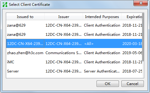
e. Select a client certificate and click OK.
f. Continue to complete creating the authentication connection.
For more information about adding authentication connections, see iNode client help.
Managing root certificate, server certificate, and CRL in UAM
You can manage the root certificate, server certificate, and CRL in UAM.
Verifying the certificates
1. Click the User tab.
2. From the navigation tree, select User Access Policy > Service Parameters > Certificate.
The page for configuring the certificate opens.
3. Click Certificate Verification.
The Certificate Verification page opens.
4. Select the following certificate and private key files:
¡ Root Certificate—Click Add Root Certificate to select a root certificate.
¡ Server Certificate File—Click Browse to select a local server certificate file.
¡ Private key is included in server certificate file—Specify whether or not the server certificate file includes the private key. If you do not select this option, you must select a private key file for the server certificate file.
¡ Private Key File of Server Certificate—Click Browse to select a private key file for the server certificate. This parameter is displayed only when the Private key is included in server certificate file option is not selected.
¡ Password of Server Private Key—Enter the password for the server private key. This password was configured when the server certificate was exported.
¡ Client Certificate—Click Browse to select a client certificate file.
¡ Private key is included in client certificate file—Specify whether or not the client certificate file includes the private key. If you do not select this option, you must select the private key file for the client certificate.
¡ Private Key File of Client Certificate—Click Browse to select a private key file for the client certificate. This parameter is displayed only when the Private key is included in client certificate file box is not selected.
¡ Client Certificate Key Password—Enter the password for the client private key. This password was configured when the client certificate was exported.
5. Click OK. The verification result is displayed for each certificate file. If the verification fails, the page displays the failure reasons.
Importing root and server certificates to UAM
When you import root and server certificates to UAM, use the following guidelines:
· UAM supports the following root and server certificate file formats:
¡ pem—Base64 encoded, using the PEM or CER format.
¡ der—Distinguished Encoding Rules encoded, using the DER or CER format.
¡ pkcs12—Public-Key Cryptography Standards # 12 encoded, using the PFX or P12 format.
· If the server certificate file is a .pfx file, you cannot use a .pvk file as the private key file. If the private key is stored in the certificate, the certificate cannot be a .der file.
· UAM supports uploading of root certificate files in a hierarchy of at most 9 levels. If the file hierarchy exceeds 9 levels, a server or client certificate file cannot be uploaded.
Importing a root certificate
1. Click the User tab.
2. From the navigation tree, select User Access Policy > Service Parameters > Certificate.
The Certificate page opens.
3. Click the Root Certificate tab.
4. Click Import EAP Root Certificate.
The page for configuring the root certificate opens.
5. Click Browse for the Root Certificate field to select a local root certificate file.
6. Click Next.
The page for configuring the CRL opens.
7. Configure the following parameters in the CRL area:
¡ Enable CRL Periodical Update—If you select this box, the CRL at a specific link is periodically updated. You can configure the update method, update interval, update time, and link.
¡ Update Type—Select the CRL update type. Options are HTTP/HTTPS and LDAP. If LDAP is selected, specify the administrator DN and password of the LDAP server.
¡ Monthly Update Cycle/Update Time—Enter the interval and time at which the CRL is updated. UAM updates the CRL at the specified time every interval.
¡ Link—Enter the URL of a CRL to be updated, in the format of http://aabbcc/dd.crl.
¡ Admin DN—Enter the absolute path for the administrator on the LDAP server.
¡ Admin Password—Enter the administrator password.
8. Click Test to check whether the CRL link is valid.
If the link is invalid, the Connection timed out message is displayed. If the link is valid, click OK to return to the root certificate configuration list. The system displays a message indicating whether the root certificate is successfully added.
Importing a server certificate
1. Click the User tab.
2. From the navigation tree, select User Access Policy > Service Parameters > Certificate.
The Certificate page opens.
3. Click the Server Certificate tab.
4. Click Import EAP Server Certificate.
The page for configuring the server certificate opens.
5. Configure the following parameters:
¡ Private key is included in certificate file—If you select the box, the server certificate and its private key are saved in the same file, and the page only displays the Server Certificate File field. If you do not select the box, the server certificate and its private key are saved in different files, and the page displays both the Server Certificate File and Private Key File of Server Certificate fields.
¡ Server Certificate File—Click Browse for the field to select a local server certificate file. If you have selected Private key is included in certificate file, the local server certificate file must contain its private key.
¡ Private Key File of Server Certificate—Click Browse for the field to select the local private key of a server certificate. If the server certificate file is a .pfx file, you cannot use a .pvk file as the private key file.
6. Click Next.
The page for configuring the server private key password opens.
7. Enter the server private key password.
The private key password protects the private keyword. This field is empty if you have not set the password.
8. Click OK to check whether the password is correct.
If the password is invalid, an error message is displayed. If the password is valid, the page returns to the server certificate configuration list. The system displays a message indicating whether the server certificate is successfully added.
9. View the following information in the Certificate Configuration Preview page:
¡ Root Certificate Issuer—Organization that issues the root certificate.
¡ Server Certificate Subject—Subject of a server certificate. This parameter identifies each certificate.
¡ Server Certificate Valid Start Time/Server Certificate Valid End Time—Set a time range for a valid server certificate.
¡ CRL Update Method—If you selected Enable CRL Periodical Update, this field displays the CRL update method, which can only be HTTP. If not, this field displays Import, which indicates that the CRL needs to be imported to UAM. The CRL link, CRL update interval, and CRL update time parameters do not exist in the page.
¡ CRL Link—URL where the CRL is updated.
¡ CRL Update Interval—Interval at which the CRL is updated.
¡ CRL Update Time—Time when the CRL is updated.
10. Click OK.
Verifying the imported certificates
1. Click the User tab.
2. From the navigation tree, select User Access Policy > Service Parameters > Certificate.
The Certificate page opens.
3. Click Verify Imported Certificate.
UAM verifies the imported root and server certificates and displays validity information for the certificates.
4. Click root or server to show the certificate information.
The root certificate information includes the issuer, subject, and type. The server certificate information includes the issuer, subject, type, valid start time, and valid end time.
5. Click Back to return to the Certificate page.
Accessing the Certification Configuration List page
1. Click the User tab.
2. From the navigation tree, select User Access Policy > Service Parameters > Certificate. The Certificate page opens.
3. Click the View
Configuration icon ![]() in the Action column for EAP Certificate
Configuration. The View Configuration icon
in the Action column for EAP Certificate
Configuration. The View Configuration icon ![]() is displayed only
after you import the root and server certificates to UAM.
is displayed only
after you import the root and server certificates to UAM.
Certificate configuration information contents
¡ Root Certificate Issuer—Organization that issues the root certificate.
¡ Server Certificate Subject—Subject of the server certificate. This parameter identifies each certificate.
¡ Server Certificate Valid Start Time/Server Certificate Valid End Time—Set a time range for the valid server certificate.
¡ CRL Link—URL where the CRL is updated.
¡ CRL Update Interval—Interval at which the CRL is updated.
¡ CRL Update Time—Time at which the CRL is updated.
¡ CRL Update Result—Result of the latest CRL update, which is a failure or a success.
¡ CRL Update Status—Indicates whether the CRL update has finished.
¡ CRL Update Failure Reason—Displays the reason why CRL update fails. You can modify the certificate configuration according to the update failure reason.
¡ Last CRL Update Time—Most recent time when the CRL was updated.
Configuring CRL update
After the root and server certificates are imported to UAM, you can independently configure the CRL update parameters.
To configure the CRL update parameters:
1. Access the Certificate Configuration List page.
2. Click the CRL
icon ![]() in the Action column for EAP Certificate Configuration. The page for configuring
the CRL update parameters opens. The CRL icon
in the Action column for EAP Certificate Configuration. The page for configuring
the CRL update parameters opens. The CRL icon ![]() is displayed only
after you import the root and server certificates to UAM.
is displayed only
after you import the root and server certificates to UAM.
3. Configure the following parameters in the CRL Configuration area:
¡ Enable CRL Periodical Update—If you select the box, the CRL at a specific link is periodically updated. Only when you select the box, you can configure the update method, update interval, update time, and link.
¡ Update Interval/Update Time—Enter the interval and time at which the CRL is updated. UAM updates the CRL at the specified time every interval.
¡ Link—Enter the URL of a CRL to be updated in the format of http://aabbcc/dd.crl.
¡ Test—Click to check whether the CRL link is valid. If the link is invalid, the Connection timed out prompt is displayed. If the link is valid, click OK.
Updating the CRL at the URL
1. Access the Certificate Configuration List page.
2. Click the Update CRL
icon ![]() in the Action
column for EAP Certificate Configuration to begin
updating the CRL. The Update CRL icon
in the Action
column for EAP Certificate Configuration to begin
updating the CRL. The Update CRL icon ![]() is displayed only after you import the root
and server certificates to UAM. The update result prompt is displayed after the CRL update is
completed.
is displayed only after you import the root
and server certificates to UAM. The update result prompt is displayed after the CRL update is
completed.
Importing a CRL file
|
|
CAUTION: If you selected Enable CRL Periodical Update, the periodically updated CRL file overwrites the manually imported CRL file. |
You can import a CRL file regardless of whether periodic CRL update is enabled.
To import a CRL file:
1. Access the Certificate Configuration List page.
2. Click the Import CRL
File icon ![]() in the Action column for EAP Certificate Configuration. The Import
CRL File icon
in the Action column for EAP Certificate Configuration. The Import
CRL File icon ![]() is displayed only after you import the root and server certificates to UAM.
is displayed only after you import the root and server certificates to UAM.
3. Click Browse for the CRL File field to select a local CRL file.
4. Click OK.
Deleting certificate configuration
1. Access the Certificate Configuration List page.
2. Click the Clear
Configuration icon ![]() in the Action column for EAP Certificate Configuration.
in the Action column for EAP Certificate Configuration.
The Clear Configuration icon ![]() is displayed only
after you import the root and server certificates to UAM.
is displayed only
after you import the root and server certificates to UAM.
3. Click OK in the page that opens.
Configuring a preferred EAP type in an access policy
The following information describes how to configure certificate authentication in an access policy. For information about access policy configuration, see "Configuring access policies."
To configure certificate authentication in an access policy:
1. Click the User tab.
2. From the navigation tree, select User Access Policy > Access Policy.
The page displays all access policies.
3. Click Add.
The Add Access Policy page opens.
4. Configure the following parameters in the Authorization Information area:
¡ Preferred EAP Type—Select a preferred EAP type. Options are EAP-TLS, EAP-TTLS, and EAP-PEAP. All these authentication types are certificate based.
¡ Subtype—Select a certificate authentication subtype from the list. Options are EAP-MSCHAPv2, EAP-MD5, and EAP-GTC. This parameter is displayed only when the preferred EAP type is set to EAP-TTLS or EAP-PEAP.
¡ EAP Auto Negotiate—Select whether to enable automatic negotiation. EAP automatic negotiation enables UAM to permit the authentication request from a client if the EAP authentication type on the client and the preferred EAP type on UAM do not match.
The supported authentication certificate types and subtypes vary by access users, as described in Table 33.
5. Configure other parameters, and then click OK.
Table 33 Authentication types and subtypes supported by different access users
|
Access user type |
Supported authentication certificate types and subtypes |
|
Common access user |
· EAP-TLS · EAP-TTLS/EAP-MD5 · EAP-TTLS/EAP-MSCHAPv2 · EAP-TTLS/EAP-GTC · EAP-TTLS/PAP · EAP-TTLS/MSCHAPv2 · EAP-PEAP/EAP-MSCHAPv2 · EAP-PEAP/EAP-MD5 · EAP-PEAP/EAP-GTC |
|
Guest |
· EAP-TLS · EAP-TTLS/EAP-MD5 · EAP-TTLS/EAP-MSCHAPv2 · EAP-TTLS/EAP-GTC · EAP-TTLS/PAP · EAP-TTLS/MSCHAPv2 · EAP-PEAP/EAP-MSCHAPv2 · EAP-PEAP/EAP-MD5 · EAP-PEAP/EAP-GTC |
|
User synchronized from Windows AD |
· EAP-TLS · EAP-PEAP/EAP-MSCHAPv2 · EAP-PEAP/EAP-MD5 · EAP-PEAP/EAP-GTC |
|
User synchronized from OpenLDAP (with a plaintext password) |
· EAP-TLS · EAP-TTLS/EAP-MD5 · EAP-TTLS/EAP-MSCHAPv2 · EAP-TTLS/EAP-GTC · EAP-TTLS/PAP · EAP-TTLS/MSCHAPv2 · EAP-PEAP/EAP-MSCHAPv2 · EAP-PEAP/EAP-MD5 · EAP-PEAP/EAP-GTC |
|
User synchronized from OpenLDAP (with a ciphertext password) |
· EAP-TTLS/EAP-MD5 · EAP-TTLS/EAP-GTC · EAP-TTLS/PAP · EAP-PEAP/EAP-MD5 · EAP-PEAP/EAP-GTC |
|
Mute terminal user |
Does not support certificate authentication. |
Configuring RSA authentication
As a third-party RADIUS authentication method, RSA authentication uses an RSA server to authenticate users. The commonly used RSA server is RSA RADIUS server.
Both UAM and RSA servers are used in RSA authentication. RSA authentication is implemented as shown in Figure 107:
· UAM receives an authentication request from a user.
· UAM checks whether the third-party authentication function is enabled in system settings.
¡ If the third-party authentication function is disabled, UAM performs local authentication.
¡ If the third-party authentication function is enabled and Third-Party RADIUS Authentication is selected, UAM forwards the request to the RSA server.
· The RSA server authenticates the user and sends the authentication result to UAM.
· UAM permits or denies the user's access to the network according to the authentication result, and uses access control policies to control the permitted user's access to the network.
Figure 107 RSA authentication involving UAM and the RSA server
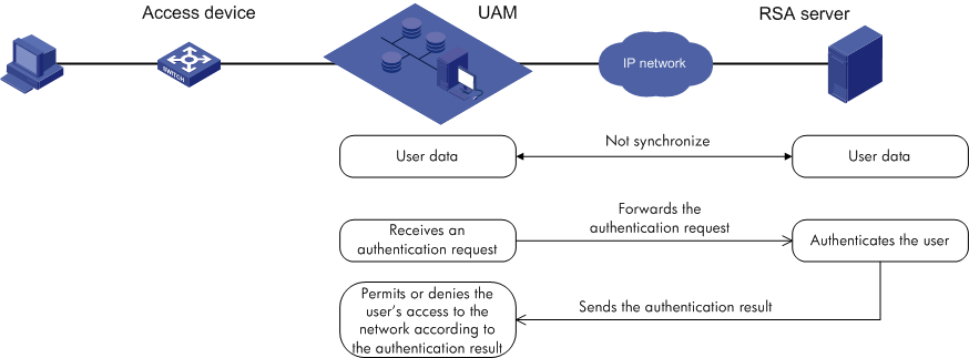
After a user passes RSA authentication for the first time, UAM synchronizes the user information from the RSA server.
For UAM to implement RSA authentication with the RSA server, configure the following in UAM:
· Add access devices. See "Configuring access devices."
· Add access conditions. See "Configuring access conditions."
· Add access policies. See "Configuring access policies."
· Add services and associate the services with access conditions and policies. See "Configuring access services."
· Configure the third-party RADIUS authentication function.
Configuring third-party RADIUS authentication
RSA authentication is a third-party RADIUS authentication method and the configuration page is accessed from the third-party authentication page.
To configure third-party RADIUS authentication:
2. From the navigation tree, select User Access Policy > Third-Party Authentication.
3. Click the Configure
icon ![]() for Third-Party Authentication
Policy.
for Third-Party Authentication
Policy.
4. Configure the following parameters:
¡ Enable Third-Party Authentication—Select this option to enable third-party authentication, and then select Third-Party RADIUS Authentication.
¡ IP Address—Enter the IP address of the RSA server.
¡ Port—Enter the port number to which the RSA server listens for authentication packets. The value must be the same as that of the listening port configured on the RSA server.
¡ Key/Confirm Key—Enter and confirm the key used for the UAM and RSA servers to authenticate each other. The value must be the same as that of the shared key configured on the RSA server.
¡ Local Password—Enter the initial password used in RSA authentication. After a user passes authentication for the first time, the user can immediately modify the local password in the self-service center. To log in to the self-service center, the user must provide an RSA dynamic password or a combination of the RSA dynamic password and local password for the RSA authentication.
¡ Password Check Mode—Select a password check mode. Options are Third-Party Password and Third-Party Password + Local Password. The Third-Party Password mode requires RSA dynamic password only, and the Third-Party Password + Local Password mode requires both the local password and RSA dynamic password.
5. In the Access Information area, specify the maximum number of concurrent online users of the same account in the Max. Concurrent Logins field. The default value is 1. If this field is empty, the concurrent login user number is not limited.
6. In the Access Service area, select one or more access services.
7. Enter a test user name and password, and then click Check Configuration to verify that the RSA authentication is correct.
8. Click OK.
Viewing RSA users in UAM
1. Click the User tab.
2. From the navigation tree, select User Access Policy > Third-Party Authentication.
3. Click the View Third-Party Users icon ![]() in the Action column.
in the Action column.
The page displays all RSA users.
Configuring roaming authentication
Roaming authentication requires at least two AAA servers. It takes place between the visited and registration networks, when a user attempts to access the visited network. The visited network server does not have the user information needed to authenticate the user, but works with the registration network server that does have the information, so the user can be authenticated.
Roaming authentication example
A roaming authentication process example, using two UAM servers, is shown in Figure 108:
1. The source UAM receives a user authentication request. However, the source UAM does not have the user information needed to authenticate the user. A source UAM is also known as a roaming UAM.
2. The source UAM forwards the authentication request to the destination UAM. A destination UAM is also known as a local UAM.
3. The destination UAM has the user information. It authenticates the user, and sends the authentication result to the source UAM.
4. Based on the authentication result, the source UAM allows or denies the user's access to the network.
Figure 108 Roaming authentication process
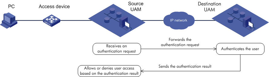
Roaming authentication prerequisites
To implement roaming authentication, both the destination UAM and the source UAM require configuration, as follows:
· On the destination UAM, configure the source UAM as an access device.
· On the source UAM, enable and configure the roaming function.
Unavailable UAM functions in roaming authentication
The following UAM functions are not available in roaming authentication:
· Binding computer name.
· Binding the computer to a Windows domain.
· Online users required to log in to a domain.
· Sending messages to online users.
· Logging out users.
Configuring the source UAM as an access device (on the destination UAM)
1. Click the User tab.
2. From the navigation tree, select User Access Policy > Access Device Management > Access Device.
3. Click Add.
The page for adding an access device opens.
4. Enter the Shared Key, Authentication Port, and Accounting Port.
The values must be the same as those in the source UAM roaming configuration. For more information, see "Configuring the roaming function (on the source UAM)."
5. Select LAN Access Service from the Service Type list.
6. Select HP(Comware) or H3C(General) from the Access Device Type list.
7. Select Ungrouped from the Service Group list.
8. Select -- from the Access Location Group list.
9. Click Add Manually in the Device List.
The page returns to the Add Access Device Manually page.
10. Enter the IPv4 address of the source UAM server in the Start IP field.
11. Click OK.
The page for adding an access device opens.
12. Click OK.
The Result of Adding Access Devices page opens.
13. Click Back to Access Device List.
Configuring the roaming function (on the source UAM)
The roaming function must be enabled and configured on the source UAM.
Enabling roaming
The roaming configuration takes effect only when the roaming function is enabled.
To enable the roaming function:
1. Click the User tab.
2. From the navigation tree, select User Access Policy > Service Parameters > System Settings.
3. On the page that opens, click the Configuration icon![]() for Roaming Configuration.
for Roaming Configuration.
4. Select Yes from the Enable Roaming list.
5. Click OK.
Accessing the roaming configuration list page
1. Click the User tab.
2. From the navigation tree, select User Access Policy > Service Parameters > System Settings.
3. On the page that opens, click the Configuration icon ![]() for Roaming Configuration.
for Roaming Configuration.
Roaming configuration list contents
¡ Identifier—Roaming type, including domain and RSA. The following describes the meaning of each option when the identifier is domain. For more information about RSA authentication, see "Configuring RSA authentication."
¡ Domain name—Domain name for roaming. If the user's authentication request contains the domain name, roaming authentication is performed.
¡ IP Address—IPv4 address of the AAA server that authenticates roaming users.
¡ Port—Port number that the destination AAA server listens to for authentication or accounting packets. If the roaming configuration type is Authentication, the field displays the port number for listening authentication packets. If the roaming configuration type is Accounting, the field displays the listening port number for accounting packets.
¡ Key—Key for the source UAM and destination AAA server to authenticate each other. The value must be the same as that configured for the destination AAA server.
¡ Type—Roaming configuration type, including Authentication and Accounting.
¡ Modify—Click
the Modify icon ![]() to modify the roaming configuration.
to modify the roaming configuration.
¡ Delete—Click
the Delete icon ![]() to delete the roaming
configuration.
to delete the roaming
configuration.
Add roaming configuration
Roaming is typically configured both for authentication and accounting. However, authentication roaming need not be configured when you use UAM for local authentication and use a separate accounting server.
Adding authentication roaming configuration
1. Access the roaming configuration list page.
2. Click Add.
The page for adding roaming configuration opens.
3. Select Domain from the Identifier list.
4. Enter a domain name in the Domain name field. If the authentication request of a user contains the domain name, roaming authentication is performed.
5. Enter the IPv4 address of the destination UAM server in the IP Address field.
6. Enter the listening port number for authentication packets in the Port field.
The value must be the same as that in the destination UAM roaming configuration. For more information, see "Configuring the source UAM as an access device (on the destination UAM)."
7. Enter a key in the Key and Confirm Key fields.
The value must be the same as that in the destination UAM roaming configuration. For more information about destination UAM roaming configuration, see "Configuring the source UAM as an access device (on the destination UAM)."
8. Select Authentication from the Type list.
9. Click OK.
Adding accounting roaming configuration
1. Access the roaming configuration list page.
2. Click Add.
The page for adding roaming configuration opens.
3. Select Domain from the Identifier list.
4. Enter a domain name in the Domain name field. If the authentication request of a user contains the domain name, roaming authentication is performed. Keep the field the same as that in authentication roaming configuration.
5. Enter the IPv4 address of the destination UAM server in the IP Address field.
6. Enter the listening port number for accounting packets in the Port field.
The values must be the same as that in the destination UAM roaming configuration. For more information, see "Configuring the source UAM as an access device (on the destination UAM)."
7. Enter a key in the Key and Confirm Key fields.
The value must be the same as that in the destination UAM roaming configuration. For more information about destination UAM roaming configuration, see "Configuring the source UAM as an access device (on the destination UAM)."
8. Select Accounting from the Type list.
9. Click Add.
Modifying roaming configuration
1. Access the roaming configuration list page.
2. Click the Modify icon ![]() for the roaming configuration you want to
modify.
for the roaming configuration you want to
modify.
3. Select domain from the Identifier list.
4. Enter a domain name in the Domain name field. If the authentication request of a user contains the domain name, roaming authentication is performed.
5. Enter the IPv4 address of the destination UAM server in the IP Address field.
6. Enter the listening port number for accounting packets in the Port field, based on your selection in step 10:
¡ If you select Authentication, enter the listening port number for authentication packets.
¡ If you select Accounting, enter the listening port number for accounting packets.
The value must be the same as that in the destination UAM roaming configuration. For more information about destination UAM roaming configuration, see "Configuring the source UAM as an access device (on the destination UAM)."
7. Enter a key in the Key and Confirm Key fields.
The value must be the same as that in the destination UAM roaming configuration. For more information about destination UAM roaming configuration, see "Configuring the source UAM as an access device (on the destination UAM)."
8. Select Authentication or Accounting from the Type list.
9. Click OK.
Deleting roaming configuration
1. Accessing the roaming configuration list page.
2. Click the Delete icon ![]() for the roaming configuration you want to
delete.
for the roaming configuration you want to
delete.
A confirmation dialog box opens.
3. Click OK.
Configuring third-party authentication
Overview
UAM works with a third-party system to authenticate third-party users, and then permits or denies user access to the network according to the authentication result.
UAM supports the following types of third-party systems:
· Third-party database
· Third-party Web service
· Customized third-party plug-in
· Third-party RADIUS authentication
When working with the third-party database, third-party users are authenticated in the third-party database. You can also configure UAM to periodically back up user information from the third-party database, and then authenticate third-party users locally.
When working with the third-party Web service, UAM uses the third-party Web service API to authenticate third-party users.
When working with the customized third-party plug-in, UAM uses the customized third-party plug-in to authenticate third-party users.
When working with the third-party RADIUS authentication function, UAM uses a third-party RADIUS server to authenticate third-party users.
Third-party authentication cannot be used together with LDAP on-demand synchronization policies. To use third-party authentication, delete LDAP on-demand synchronization policies from UAM. When the third-party authentication function is enabled, LDAP on-demand synchronization policies cannot be configured.
For Third-Party Web Service and Customize Third-Party Plugin, if Access the Web Interface for Authentication is selected from the Identity Check Mode list, CHAP, PEAP/MSCHAPv2, and TTLS/MSCHAPv2 are not supported.
The third-party RADIUS authentication supports only the following credential transmission methods: CHAP, PAP, EAP-MD5, PEAP-MD5, and PEAP-GTC.
If the third-party RADIUS authentication uses the CHAP authentication method, only the third-party password validation is supported. The third-party password and local password cannot be validated at the same time.
If the third-party RADIUS authentication uses the CHAP authentication method, the Check Configuration function is not available.
Viewing third-party authentication configuration
1. Click the User tab.
2. From the navigation tree, select User Access Policy > Third-Party Authentication.
The Third-Party Authentication page opens.
Third-party authentication list contents
¡ Configuration Name—Name of the third-party authentication configuration in UAM. UAM has only one third-party authentication configuration with the fixed name of Third-Party Authentication Policy.
¡ Status—State of third-party authentication: Enabled or Disabled.
¡ Authentication Type—Type of the third-party system. The value can be Third-Party Database, Third-Party Web Service, or Customize Third-Party Plugin.
¡ Action—This
field provides the Configure
icon ![]() and the View Third-Party
Users icon
and the View Third-Party
Users icon ![]() . Click the Configure icon
. Click the Configure icon ![]() to configure the
third-party authentication settings. Click the View
Third-Party Users icon
to configure the
third-party authentication settings. Click the View
Third-Party Users icon ![]() to view third-party access users.
to view third-party access users.
Configuring the third-party database
1. Access the Third-Party Authentication page.
2. Click the Configure icon ![]() .
.
The Third-Party Authentication Policy page opens.
3. Configure the following parameters:
¡ Enable Third-Party Authentication—Select this option to enable third-party authentication, and then select Third-Party Database.
¡ Authentication Method—Select an authentication method. Options are Third-Party Authentication First and Local Authentication First.
- Third-Party Authentication First—To authenticate a third-party user, UAM first searches the third-party database. If the third-party database cannot be connected, UAM uses the local database.
- Local Authentication First—To authenticate a third-party user, UAM first searches the local database. If no match is found, UAM uses the third-party database.
4. In the Basic Information area, configure the following parameters:
¡ Database Type—Select a type for the third-party database from the list. Options are SQLServer, MySQL, and Oracle. To select the Oracle option, you must install the Oracle client on the IMC server and configure the service on the Oracle client.
¡ Database User Name—Enter the user name to log in to the third-party database.
¡ Database Password—Enter the password of the database user name.
¡ Database Server Address—Enter the IP address of the database server. This parameter does not appear when the database type is Oracle.
¡ Database Name—Enter the name of the third-party database. This parameter does not appear when the database type is Oracle.
¡ Database Server Port—Enter the port number to connect to the third-party database. This parameter does not appear when the database type is Oracle.
¡ Database Instance—Enter the instance of the SQL server database. If this parameter is not specified or UAM fails to find out the instance, UAM uses the default instance of the SQL server database. This parameter is displayed only when Database Type is set to SQLServer.
¡ Database Character Set—Enter the database character set. Make sure the database character set specified in UAM is same as that configured in the MySQL database. This parameter is displayed only when Database Type is set to MySQL.
¡ User Identity—Select the identity to connect to the Oracle database. Options are Normal, SYSDBA, and SYSOPER. This parameter is displayed only when Database Type is set to Oracle.
¡ Database Service Name—Enter the name of the service to connect to the Oracle database. When configuring the service on the Oracle client, configure parameters such as the IP address. This parameter is displayed only when Database Type is set to Oracle.
¡ Test Connectivity—Click Test Connectivity to test whether UAM can connect to the database.
5. In the Collaboration Policy area, configure the following parameters for backup:
¡ User Group—Select the user group to which users synchronized from the third-party database are assigned in UAM.
¡ Password Encryption Type—Select the password encryption type of the third-party database from the list. Options are Plaintext, RC5, IDEA, DES, 3DES, MD5, and Custom.
¡ 16-bit (Default 32-bit)—Select this option to use 16-bit MD5 encryption type to encrypt user passwords in the database. If you do not select this option, 32-bit MD5 encryption type is used. This option is available only when MD5 is selected for Password Encryption Type.
¡ Encode the encryption result with Base64—Select this option to encode plaintext or ciphertext passwords with Base64. You can select this option for all password encryption types except the Custom option.
¡ Encryption Key—Enter a key used to encrypt user passwords. If RC5, IDEA, DES, or 3DES is selected for Password Encryption Type, you must specify a value in the Encryption Key field. If DES is selected, the encryption key must be eight characters.
¡ Import Password Plugin—To import a customized encryption or decryption plug-in, click Import Password Plugin. On the Import Password Plugin window, click Browse to select the plug-in and click OK. This parameter is displayed only when Password Encryption Type is set to Custom. The Windows operating system supports importing only the files with the .dll suffix. The Linux operating system supports importing only the files with the .so suffix.
¡ Download Password Plugin Header—Click the link to download the header file com_h3c_imc_acm_common_util_EncryptPlugin.h. The header file is used to customize the password plug-in. You must implement the methods defined in this header file when customizing the password plug-in.
The password encryption or decryption plug-in is developed based on the provided header file. The plug-in varies by the bit version (32 or 64) of the JDK installed in the system. For example, 64-bit JDK can load only 64-bit Dynamic Link Libraries.
Use the following guidelines to generate the .dll or .so file:
- Select the JDK of the same bit version (32 or 64) as the JDK installed on the iMC server.
- Make sure the version of the selected JDK is not higher than the version of the JDK installed on the iMC server.
Figure 109 In Linux, use the GNU C++ compiler as a best practice.
¡ Authentication SQL—Enter a SQL statement to query and obtain a user password saved in the third-party database. When the Third-Party Authentication First option is selected, the Authentication SQL parameter is required. When the Local Authentication First option is selected, the Authentication SQL parameter is optional.
The default value of Authentication SQL is in the format SELECT [Password Field] FROM [Table/View Name] WHERE [Username Field] = ?. If you want to include the expiration time in the query result, specify the value in the format SELECT [Password Field] [Expiration Time] FROM [Table/View Name] WHERE [Username Field] = ?.
Authentication SQL supports multiple query criteria. You can add query criteria to the authentication SQL.
¡ Support Backup—Select this option to enable UAM to back up data in the third-party database to UAM database.
¡ Delete Local User—Select this option to delete a user from UAM database if the user does not exist in the third-party database.
¡ Backup SQL—Click Edit. Enter a SQL statement in the dialog box. Click Test to check for SQL statement incorrectness. Click OK. UAM automatically uses the backup SQL to query the third-party database and fills the obtained data in the lists of the fields. Use the alias if you query data in multiple tables that have the same fields. For example, if both table A and table B have the ID field, the SQL statement is SELECT a.ID AS AID, b.ID AS BID FROM A a, B b.
¡ Backup Interval—Specify the backup interval. Every n Days m Hour indicates that UAM backs up data in the third-party database at m every n days.
¡ User Name/ID Number/Account Name/Password—Select the corresponding attribute in the database you want to back up as the User Name, ID Number, Account Name, or Password field in UAM. Available options for each field include all the attributes that UAM obtained from the database by using the backup SQL. These attributes must be backed up from the third-party database.
¡ Add More—Click Add More to select other backup parameters:
- Telephone
- Contact Address
- End Time
- Max. Idle Time (Minutes)
- Max. Concurrent Logins
- Login Message
- Device IP
- Port
- VLAN ID/Inner VLAN ID
- Outer VLAN ID
- User SSID
- Device SN
|
|
NOTE: When data is backed up from the third-party database to UAM, only the values of the specified backup parameters are updated on UAM. Values of the parameters manually configured for third-party users on UAM are not updated. |
6. In the Access Information area, specify the maximum number of concurrent online users of the same account in the Max. Concurrent Logins field. The default value is 1. If this field is empty, the concurrent login user number is not limited.
7. In the Access Service area, select one or more access services. The third-party authentication configuration applies to all access users that use the selected services.
8. Enter a test user name and password, and then click Check Configuration to verify that the third-party authentication configuration is correct.
9. Click OK.
Configuring the third-party Web service
1. Access the Third-Party Authentication page.
2. Click the Configure icon ![]() .
.
The Third-Party Authentication Policy page opens.
3. Configure the following third-party authentication parameters:
¡ Enable Third-Party Authentication—Select this option to enable third-party authentication and select Third-Party Web Service.
¡ Authentication Method—Select an authentication method. Options are Third-Party Authentication First and Local Authentication First.
- Third-Party Authentication First—To authenticate a third-party user, UAM first uses a third-party Web service API. If the third-party Web service API cannot be used, UAM uses the local database.
- Local Authentication First—To authenticate a third-party user, UAM first searches the local database. If no match is found, UAM uses the third-party Web service API.
4. In the Basic Information area, configure the following parameters:
¡ Web Interface Method—Select a Web service API from the list. Options are HTTP/HTTPS and REST.
When the HTTP/HTTPS option is selected, the system sends authentication requests to the specified third-party service URL by using the specified user name and password.
When the REST option is selected, the system sends authentication requests to the specified third-party service URL. The URL must include the fields ${username} and ${password} to indicate the user name and the password.
¡ Request Mode—Select a mode for UAM to send authentication requests to the third-party service URL. Options are GET and POST.
¡ Identity Check Mode—Select a user identity check mode from the list. Options are Access the Web interface for authentication and Use the password returned by the Web interface for authentication.
- Access the Web interface for authentication—The third-party Web service API authenticates the user and then sends the authentication result back to UAM.
- Use the password returned by the Web interface for authentication—UAM uses the password returned by the third-party Web service API to authenticate the user.
¡ Web Service URL—Enter the URL of the third-party Web service.
¡ Username—Enter a user name that identifies the user in packets sent from UAM to the Web service API.
¡ Password—Enter the password of the user name. This parameter is displayed only when Identity Check Mode is set to Access the Web interface for authentication.
¡ AuthN Success Identifier—Enter a character string. The authentication process is considered to be successful only when the returned value set includes this identifier. This parameter is displayed only when Identity Check Mode is set to Access the Web interface for authentication.
¡ String Before Failure Message/String After Failure Message—Enter a character string in the two fields. When Access the Web interface for authentication is selected from the Identity Check Mode list, you must specify these two fields to obtain the authentication failure message. If you do not specify these two fields, all characters returned by the Web service API are treated as the authentication failure message. This parameter is displayed only when Identity Check Mode is set to Access the Web interface for authentication.
¡ String Before Password/String After Password—Enter a character string in the two fields. When Use the password returned by the Web interface is selected from the Identity Check Mode list, you must specify these two fields to obtain user's password for authentication. If you do not specify these two fields, all characters returned by the Web service API are treated as the password. This parameter is displayed only when Identity Check Mode is set to Use the password returned by the Web interface for authentication.
¡ User Group—Select the user group to which users synchronized from the third-party database are assigned in UAM.
¡ Password Encryption Type—Select a password encryption type from the list. Options are Plaintext, DES, 3DES, MD5, IDEA, RC5, and Custom.
¡ 16-bit (Default 32-bit)—Select this option to use 16-bit MD5 encryption type to encrypt user passwords in the third-party Web service. If you do not select this option, 32-bit MD5 encryption type is used. This option is available only when MD5 is selected for Password Encryption Type.
¡ Encode the encryption result with Base64—Select this option to encode plaintext or ciphertext passwords with Base64. You can select Encode the encryption result with Base64 for all password encryption types except the Custom option.
¡ Import Password Plugin—To import a customized encryption or decryption plug-in, click Import Password Plugin. On the Import Password Plugin window, click Browse to select the plug-in and click OK. This parameter is displayed only when Password Encryption Type is set to Custom.
¡ Download Password Plugin Header—Click the link to download the header file com_h3c_imc_acm_common_util_EncryptPlugin.h. The header file is used to customize the password plug-in. You must implement the methods defined in this header file when customizing the password plug-in.
¡ Add users by third party—Select this option if you want to create accounts through the third-party Web server for users that pass authentication. If you do not select this option, UAM will create accounts for users that pass authentication. This option is displayed only when Identity Check Mode is set to Access the Web Interface for Authentication.
¡ The operator must login to use the Web interface—Select this option if the third-party Web service API requires that the operator must log in.
¡ Operator/Password—Enter a user name and password for the operator to log in to the third-party Web service system.
5. In the Access Information area, specify the maximum number of concurrent online users of the same account in the Max. Concurrent Logins field. The default value is 1. If this field is empty, the concurrent login user number is not limited.
6. In the Access Service area, select one or more access services. The third-party authentication configuration applies to all access users that use the selected services.
7. Enter a test user name and password, and then click Check Configuration to verify that the third-party authentication configuration is correct.
8. Click OK.
Configuring the customized third-party plug-in
1. Access the Third-Party Authentication page.
2. Click the Configure
icon ![]() .
.
The Third-Party Authentication Policy page opens.
3. Configure the following parameters:
¡ Enable Third-Party Authentication—Select this option to enable third-party authentication and select Customize Third-Party Plugin.
¡ Authentication Method—Select an authentication method. Options are Third-Party Authentication First and Local Authentication First.
- Third-Party Authentication First—To authenticate a third-party user, UAM first uses a third-party plug-in. If the third-party plug-in cannot be used, UAM uses the local database.
- Local Authentication First—To authenticate a third-party user, UAM first searches the local database. If no match is found, UAM uses the third-party plug-in.
4. In the Basic Information area, configure the following parameters:
¡ Identity Check Mode—Select a user identity check mode from the list. Options are Access the Web interface for authentication and Use the password returned by the Web interface for authentication.
- Access the Web interface for authentication—The third-party plug-in interface authenticates the user and then sends the authentication result back to UAM.
- Use the password returned by the Web interface for authentication—UAM uses the password returned by the third-party plug-in interface to authenticate the user.
¡ User Group—Select the user group to which users synchronized from the third-party database are assigned in UAM.
¡ Process Username—Select Remove Service Suffix or Keep Service Suffix. For user names in X@Y format, the system removes or keeps the @Y part depending on your configuration.
¡ Add users by third party—Select this option if you want to create accounts through the third-party plug-in for users that pass authentication. If you do not select this option, UAM will create accounts for users that pass authentication. This option is displayed only when Identity Check Mode is set to Access the Web Interface for Authentication.
¡ Support Backup—Select this option to enable UAM to back up data in the third-party database to UAM database.
¡ Delete Local User—Select this option to delete the user from UAM database if the user does not exist in the third-party plug-in.
¡ Backup Interval—Specify the backup interval. Every n Days m Hour indicates that UAM backs up data in the third-party plug-in at m every n days.
5. In the Access Information area, specify the maximum number of concurrent online users of the same account in the Max. Concurrent Logins field. The default value is 1. If this field is empty, the concurrent login user number is not limited.
6. In the Access Service area, select one or more access services. The third-party authentication configuration applies to all access users that use the selected services.
7. Enter a test user name and password, and then click Check Configuration to verify that the third-party authentication configuration is correct.
8. Click OK.
To customize the third-party plug-in, perform the following operations based on the RESTful API provided by UAM:
1. Implement the authenticate method defined in the com.h3c.imc.acm.thirdPartyAuth.pluginAuth.func.ThirdPartPluginMgr interface. If Support Backup is selected, you must implement the processUserData method in this interface.
2. Use a text editor to open the acmAuthNPluginCfg.xml file in the directory uamthirdpartyauth\conf of the IMC installation path, and replace com.h3c.imc.acm.thirdPartyAuth.pluginAuth.func.ThirdPartPluginMgrImpl with the complete path of the implementation class.
3. Compile the implementation class into a class file, generate a .jar package, and store the package in the directory uamthirdpartyauth\repository\imc\jars of the IMC installation path.
4. Restart the uamThirdAuth process.
Configuring third-party RADIUS authentication
1. Access the Third-Party Authentication page.
2. Click the Configure
icon ![]() .
.
The Third-Party Authentication Policy page opens.
3. Select Enable Third-Party Authentication, and then select Third-Party RADIUS Authentication.
4. In the Basic Information area, configure the following parameters:
¡ IP Address—Enter the IP address of the RSA server.
¡ Port—Enter the port number to which the RSA server listens for authentication packets. The value is the same as that of the listening port configured on the RSA server.
¡ Key/Confirm Key—Enter and confirm the key used for the UAM and RSA servers to authenticate each other. The value must be the same as that of the shared key configured on the RSA server.
¡ Local Password—Enter the initial password used in RSA authentication. After a user passes authentication for the first time, the user can immediately modify the local password in the self-service center. To log in to the self-service center, the user must provide an RSA dynamic password or a combination of the RSA dynamic password and local password for the RSA authentication.
¡ Password Check Mode—Select a password check mode. Options are Third-Party Password and Third-Party Password + Local Password. The Third-Party Password mode requires the third-party password only, and the Third-Party Password + Local Password mode requires both the local password and the third-party password.
5. In the Access Information area, specify the maximum number of concurrent online users of the same account in the Max. Concurrent Logins field. The default value is 1. If this field is empty, the concurrent login user number is not limited.
6. In the Access Service area, select one or more access services.
7. Enter a test user name and password, and then click Check Configuration to verify that the third-party RADIUS authentication is correct.
8. Click OK.
Viewing the third-party user list
1. Access the Third-Party Authentication page.
2. Click the View Third-Party Users icon ![]() .
.
The page displays third-party users
backed up from the third-party system to UAM and local access users in UAM. A
third-party user is indicated by the ![]() icon before its
account name.
icon before its
account name.
UAM provides the same management functions for third-party users and access users. For more information, see "Managing access users."
Customizing terminal pages
UAM provides the following types of terminal page sets:
· Portal page sets
· User and guest preregistration pages
· BYOD page sets
· Self-service login pages
UAM offers operators a graphical page editing tool for customizing terminal page sets for PC/tablet and cell phone users. You can quickly create a page by using a predefined template that is preloaded with most parameters, or create a page from a blank template. For information about creating terminal pages, see UAM Terminal Page Customization Guide.
To open UAM Terminal Page Customization Guide:
1. Click the Help link in the upper right corner of the IMC page. The main help page opens.
2. From the left content table, select User Access Manager Help > Operation Guide > Access Service Policy > Customize Terminal Pages.
3. Click Portal Page, Preregistration Page, or BYOD Page.
4. On the page that opens, click the UAM Terminal Page Customization Guide link.
Managing and applying portal page sets
In UAM, a portal page configuration is referred to as a page set, which is a set of portal pages involved in portal Web authentication, paths and file names of the page files, and a description. The page set includes the authentication page, authentication success page, heartbeat page, and password change page.
Depending on the type of endpoint terminal, portal page sets are divided into PC portal page sets and cell phone portal page sets.
Managing PC portal page sets
There are three types of PC portal page sets in UAM:
· Predefined portal page sets—Portal page sets predefined in UAM.
· Template-based portal page sets—Portal page sets that are created based on predefined templates.
· Imported portal page sets—External portal page sets that are imported into UAM.
Accessing the PC portal page set list page
1. Click the User tab.
2. From the navigation tree, select User Access Policy > Customize Terminal Pages > Portal Page.
3. Click the PC tab.
The tab consists of a template area and a PC portal page set list.
Figure 110 Portal page
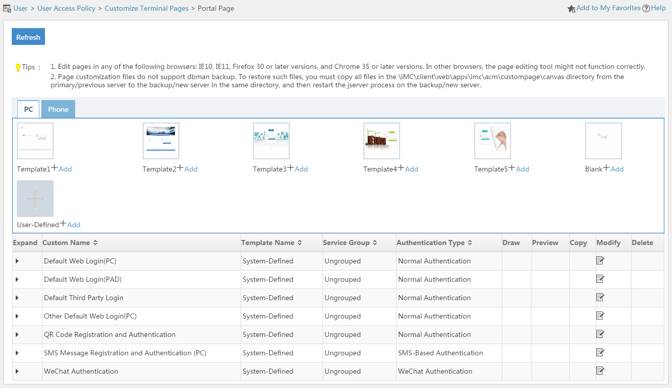
Template area
UAM provides five content templates, one blank template, and one user-defined template.
¡ Content templates—Provides editable sample PC portal page sets. You can quickly create a portal page set by editing the template.
¡ Blank template—Allows you to create PC portal page sets from scratch.
¡ User-defined template—Allows you to import external portal page sets to UAM.
PC portal page set list contents
¡ Expand—Click the Expand icon ![]() to expand the portal page set details area. The area contains a description and the file path and names of
the authentication page, authentication success page, heartbeat page, and password change page. Click the Collapse icon
to expand the portal page set details area. The area contains a description and the file path and names of
the authentication page, authentication success page, heartbeat page, and password change page. Click the Collapse icon ![]() to collapse the area.
to collapse the area.
¡ Custom Name—Name of the PC portal page set, which must unique among portal page set names.
¡ Template Name—Name of the template on which the portal page set is based. User-Defined indicates the page set is an external page set imported to UAM. Blank indicates the page set is created from scratch by using the blank template. Predefined indicates the page set is predefined by UAM.
¡ Draw—Provides links to edit the portal pages. This field is empty if the Template Name field displays Predefined or User Defined.
- Click the Authentication Page icon ![]() to
edit the authentication page.
to
edit the authentication page.
- Click the Authentication Success Page
icon ![]() to edit the authentication success page.
to edit the authentication success page.
- Click the Heartbeat Page icon ![]() to edit the heartbeat page.
to edit the heartbeat page.
- Click the Password Change Page icon ![]() to edit the password
change page.
to edit the password
change page.
¡ Preview—Provides links to preview the portal pages. This field is empty if the Template Name field displays Predefined or User Defined.
- Click the Authentication Page icon ![]() to preview the authentication page.
to preview the authentication page.
- Click the Authentication Success Page
icon ![]() to preview the authentication success page.
to preview the authentication success page.
- Click the Heartbeat Page icon ![]() to preview the heartbeat page.
to preview the heartbeat page.
- Click the Password Change Page icon ![]() to preview the
password change page.
to preview the
password change page.
¡ Copy—Click the Copy icon ![]() to create a new copy of the portal page set. This field is empty if the Template Name
field displays Predefined or User Defined.
to create a new copy of the portal page set. This field is empty if the Template Name
field displays Predefined or User Defined.
¡ Modify—Click the Modify icon ![]() to modify the portal page set.
to modify the portal page set.
¡ Delete—Click the Delete icon ![]() to delete the portal
page set. This field is empty
if the Template Name field displays Predefined.
to delete the portal
page set. This field is empty
if the Template Name field displays Predefined.
Managing predefined PC portal page sets
UAM predefines the following PC portal page sets:
· Default Web Login (PC)—Default Web authentication page for PC users.
· Default Web Login (PAD)—Default Web authentication page for all smart device users who use medium-sized screens, such as iPads.
· Default Third Party Login—Default Web authentication page for the third party.
· Other Default Web Login (PC)—Default Web authentication page for PC users.
· QR Code Registration and Authentication—Web page for automatic registration and portal authentication of guests through QR code scanning.
· SMS Message Registration and Authentication (PC)—Web page for registration and authentication of guests through a phone number.
You cannot edit, preview, copy, or delete a predefined PC portal page set. However, you can replace the portal pages or change the page file paths and names. A predefined PC portal page set can be used by UAM services immediately after being modified.
To modify a predefined PC portal page set:
1. Access the PC portal page set list page.
2. Click the Modify
icon ![]() for the predefined
PC portal page set.
for the predefined
PC portal page set.
The Modify Custom Portal Page opens.
Figure 111 Modify Custom Portal Page
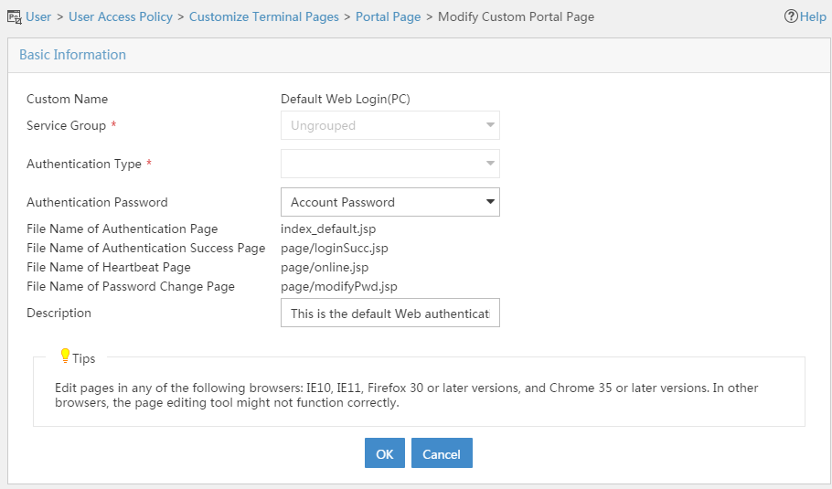
3. Modify the following parameters:
¡ Custom Name—Cannot be modified.
¡ Service Group—Cannot be modified.
¡ File Path—Modify the path where the page files are stored. By default, the page files are stored in the /client/web/apps/portal/ directory of the IMC installation path. You can save the files to a subdirectory under the default directory.
¡ File Name of Authentication Page—Modify the file pathname of the portal authentication page. The file must be in JSP format.
¡ File Name of Authentication Success Page—Modify the file pathname of the authentication success page. The file must be in JSP format.
¡ File Name of Heartbeat Page—Modify the file pathname of the heartbeat page. The file must be in JSP format.
¡ File Name of Password Change Page—Modify the file pathname of the password change page. The file must be in JSP format.
|
|
NOTE: You must first create the specified directories in the /client/web/apps/portal directory of the IMC installation path on the IMC server, and save the portal page files to their respective directories. |
¡ Description—Modify the description of the portal page set.
4. Click OK.
Managing template-based portal page sets
You can copy, modify, delete, edit, and preview PC portal page sets that are created based on a content template or the blank template.
Adding a template-based portal page set
UAM provides five content templates and a blank template.
To add a portal page set based on a template:
1. Access the PC portal page set list page.
2. Click Add for a content template or the blank template.
The Add Custom Portal Page opens.
3. Configure the following parameters:
¡ Custom Name—Specify a unique name for the PC portal page set.
¡ Service Group—Select the service group to which the portal page set belongs.
¡ Description—Modify the description of the portal page set.
4. Click OK.
UAM auto-populates the file name and path information of the portal pages.
Copying a template-based portal page set
You can create a new portal page set by copying an existing portal page set.
To copy a portal page set:
5. Access the PC portal page set list page.
6. Click the Copy icon ![]() for a portal page set.
for a portal page set.
The Copy Custom Portal Page opens.
7. Configure the following parameters:
¡ Custom Name—By default, the page set is named copy + original page set name. You can specify a new name for the portal page set. The name must unique among all portal page set names.
¡ Service Group—Cannot be modified.
¡ Description—Specify a description for the portal page set.
8. Click OK.
UAM auto-populates the file name and path information of the portal pages.
Modifying a template-based portal page set
You can only modify the description of a portal page set that is created based on a template.
To modify a portal page set:
9. Access the PC portal page set list page.
10. Click the Modify
icon ![]() for the
portal page set.
for the
portal page set.
11. Modify the description of the portal page set.
12. Click OK.
Deleting a template-based portal page set
You cannot delete a portal page set that is being used by an authentication page or a portal port group.
To delete a portal page set:
13. Access the PC portal page set list page.
14. Click the Delete
icon ![]() for the
portal page set.
for the
portal page set.
A confirmation dialog box opens.
15. Click OK.
Editing a template-based portal page
A PC portal page set contains an authentication page, an authentication success page, a heartbeat page, and a password change page. You can edit these pages.
You must publish a portal page in order to make it available to other UAM functions.
To edit a portal page set:
16. Access the PC portal page set list page.
17. Click the Draw Authentication Page icon ![]() , Draw Authentication
Success Page icon
, Draw Authentication
Success Page icon ![]() , Draw
Heartbeat Page icon
, Draw
Heartbeat Page icon ![]() , or Draw Password Change Page icon
, or Draw Password Change Page icon ![]() in the Draw column of a portal page set.
in the Draw column of a portal page set.
The page opens in a drawing canvas:
18. Move your mouse pointer to the middle right of the drawing canvas to display the option menu.
19. Edit the page as needed. For more information, see UAM Terminal Page Customization Guide.
20. Click the Save menu option to save the page.
21. Click the Close menu option to close the drawing canvas.
Previewing a template-based portal page
22. Access the PC portal page set list page.
23. Click the Preview Authentication
Page icon ![]() , Preview Authentication Success Page icon
, Preview Authentication Success Page icon ![]() , Preview Heartbeat
Page icon
, Preview Heartbeat
Page icon ![]() , or Preview Password Change Page icon
, or Preview Password Change Page icon ![]() in
the Preview column of a portal page set.
in
the Preview column of a portal page set.
The Preview window displays the preview image of the page.
Publishing a template-based portal page
A portal page must be published before it can be used by other UAM functions.
You must publish each portal page contained in a portal page set individually.
To publish a portal page:
24. Access the PC portal page set list page.
25. Click the Publish Authentication
Page icon ![]() , Publish Authentication Success Page icon
, Publish Authentication Success Page icon ![]() , Publish Heartbeat
Page icon
, Publish Heartbeat
Page icon ![]() , or Publish Password Change Page icon
, or Publish Password Change Page icon ![]() in
the Draw column of a portal page set.
in
the Draw column of a portal page set.
The page opens in a drawing canvas.
26. Move your mouse pointer to the middle right of the drawing canvas to display the option menu.
27. Click the Publish menu option.
UAM automatically saves the page and then publishes the page to portal servers.
Managing imported portal page sets
You can import external portal page sets to UAM as user-defined portal page sets.
Imported portal page sets have a template name of User Defined.
Because the embedded editing tool of UAM is not compatible with third-party editing software, you cannot edit, preview, or copy an imported portal page set. UAM only allows you to modify and delete an imported portal page set.
You can use an imported portal page set in UAM functions immediately after the page is imported or modified.
Importing an external portal page set
1. Access the PC portal page set list page.
2. Click Add for the User Defined template.
The Add Custom Portal Page opens.
Figure 112 Add Custom Portal Page
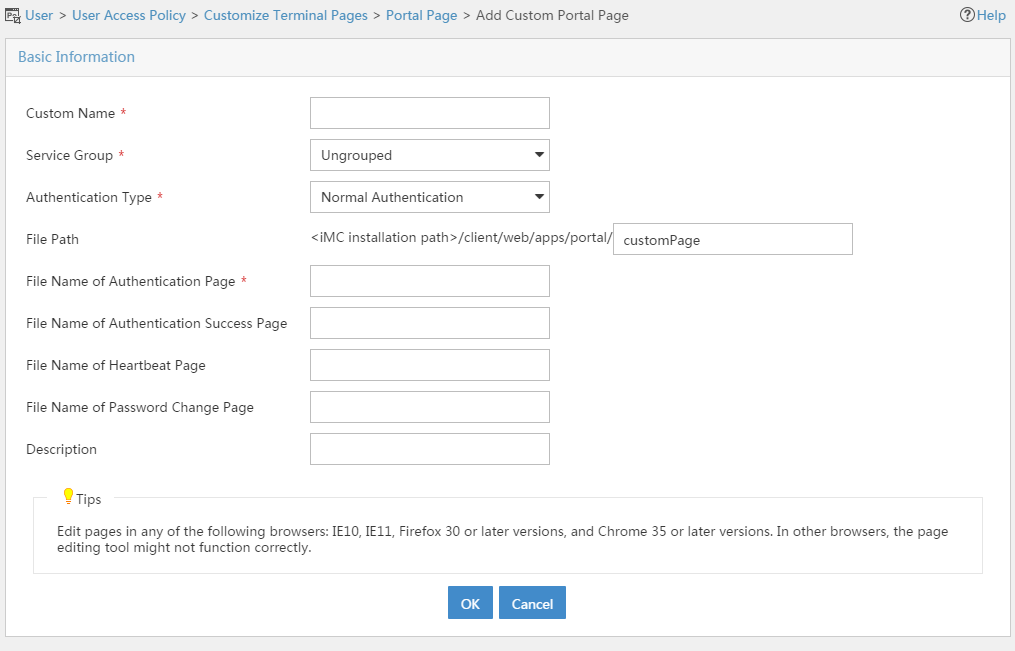
3. Configure the following parameters:
¡ Custom Name—Enter the name of the portal page set, which must unique among all portal page set names.
¡ Service Group—Select a service group to which the portal page set belongs.
¡ File Path—Specify the path where the portal page files are stored. By default, the page files are stored in the /client/web/apps/portal directory of the IMC installation path. You can save the files to a subdirectory under the default directory.
¡ File Name of Authentication Page—Specify the file pathname of the authentication page. The file must be in JSP format.
¡ File Name of Authentication Success Page—Specify the file pathname of the authentication success page. The page file must be in JSP format.
¡ File Name of Heartbeat Page—Specify the file pathname of the heartbeat page. The file must be in JSP format.
¡ File Name of Password Change Page—Specify the file pathname of the password change page. The file must be in JSP format.
|
|
NOTE: You must first create the specified directories in the /client/web/apps/portal/ directory of the IMC installation path on the IMC server, and save the portal page files to their respective directories. |
¡ Description—Enter a description for the imported portal page set.
4. Click OK.
Modifying an imported portal page set
You cannot edit the content of the portal pages contained in an imported portal page set, but you can replace the portal pages or change the locations where the portal page files are saved.
An imported portal page set can be used in UAM functions immediately after being modified.
To modify an imported portal page set:
1. Access the PC portal page set list page.
2. Click the Modify
icon ![]() for the
portal page set.
for the
portal page set.
The Modify Custom Portal Page opens.
3. Modify the parameters except Custom Name for the portal page set.
4. Click OK.
Deleting an imported portal page set
You cannot delete an imported portal page set that is being used by an authentication page or a portal port group.
Deleting an imported portal page set does not delete page files from IMC.
To delete an imported portal page set:
1. Access the PC portal page set list page.
2. Click the Delete
icon ![]() for the
imported portal page set you want to delete.
for the
imported portal page set you want to delete.
A confirmation dialog box opens.
3. Click OK.
Managing cell phone portal page sets
UAM offers the same management functions for PC portal page sets and cell phone portal page sets. For information about managing cell phone portal page sets, see "Managing PC portal page sets."
Table 34 describes the differences between PC portal page sets and cell phone portal page sets. For more information about editing portal pages, see UAM Terminal Page Customization Guide.
Table 34 Differences between cell phone portal page sets and PC portal page sets
|
Item |
Cell phone portal page sets |
PC portal page sets |
|
Predefined portal page set |
Five predefined portal page sets for PDA users and cell phone users. |
Six predefined portal page sets for PC users, PAD users, and guests. |
|
System-defined template |
Seven content templates and one blank template. |
Five content templates and one blank template. |
Applying portal page sets to users
After publishing a portal page set, configure a page push policy to reference the portal login page. UAM pushes the portal login page to users who match the policy.
To configure a published portal login page for a page push policy:
1. Configure access conditions to be used by the page push policy. Page push policies filter users based on various access conditions, which should be configured in advance on the Access Condition page, as shown in Figure 112.
Figure 113 Configuring access conditions
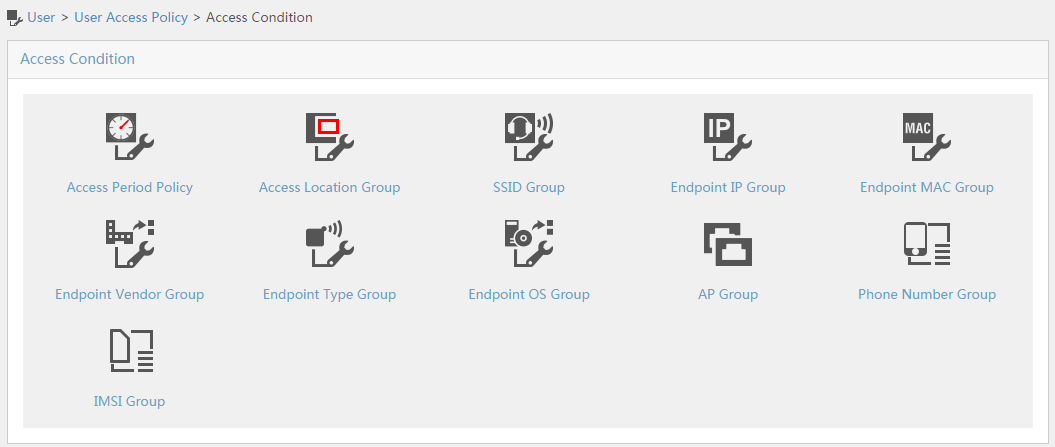
2. Configure a page push policy for portal authentication, as shown in Figure 113.
Figure 114 Configuring a page push policy for portal authentication
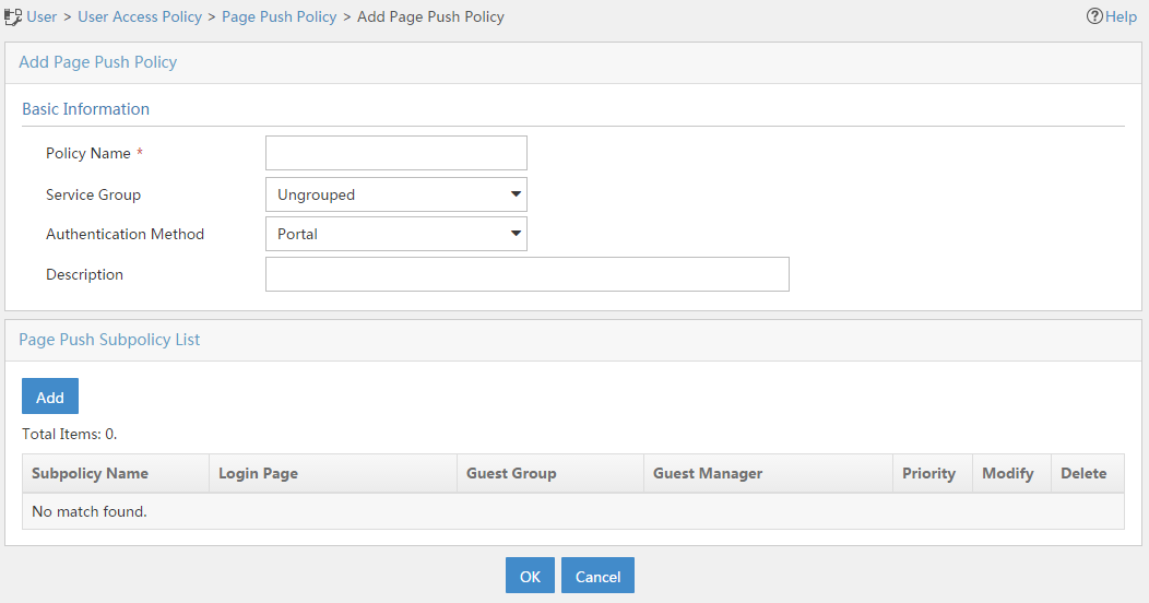
3. Add a subpolicy to the page push policy. In the subpolicy, configure the access conditions as needed, and then select the published portal login page, as shown in Figure 114.
Figure 115 Adding a subpolicy to the page push policy
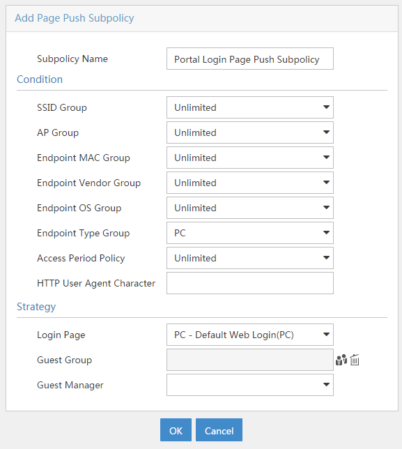
Managing and applying preregistration page sets
Preregistration pages are divided into PC preregistration pages (designed for PCs and PADs) and cell phone preregistration pages.
The following sections describe how to manage and apply these two types of preregistration pages.
Managing PC preregistration pages
In UAM, a preregistration page configuration is referred to as a page set, which includes a page set name, the preregistration page, path and name of the page file, and a description.
There are two types of preregistration page sets in UAM:
· Template-based preregistration page sets—Preregistration pages that are created based on predefined templates.
· Imported preregistration page sets—External preregistration pages that are imported into UAM.
The following sections describe these two types of preregistration pages separately.
Accessing the PC preregistration page list page
1. Click the User tab.
2. From the navigation tree, select User Access Policy > Customize Terminal Pages > Preregistration Page.
3. Click the PC tab.
The tab consists of a template area and a preregistration page set list.
Figure 116 Preregistration page
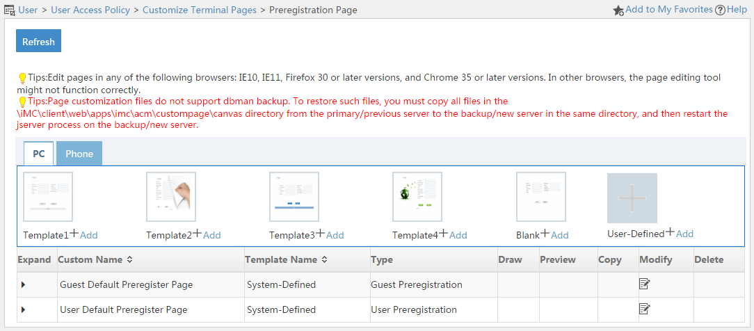
Template area
UAM provides four content templates (templates 1 to 4), one blank template, and one user-defined template for creating PC preregistration pages.
¡ Content templates—Provides editable sample PC preregistration pages. You can quickly create a preregistration page by editing the template.
¡ Blank template—Allows you to create a PC preregistration page from scratch.
¡ User-defined template—Allows you to import external preregistration pages to UAM.
Preregistration page set list contents
¡ Expand—Click the Expand icon ![]() to expand the preregistration page details area. The area contains the file path of the page, the page URL, and a
description. Click the Collapse icon
to expand the preregistration page details area. The area contains the file path of the page, the page URL, and a
description. Click the Collapse icon ![]() to collapse the area.
to collapse the area.
¡ Custom Name—Unique name of the preregistration page.
¡ Template Name—Name of the template based on which the preregistration page is created. User-Defined indicates the preregistration page is an external page imported to UAM. Blank indicates the page is created from scratch by using the blank template.
¡ Type—Type of the page: User Preregistration or Guest Preregistration.
¡ Draw—Click the User Preregistration or Guest Preregistration icon ![]() to edit the preregistration page. This field is empty if the Template Name
field displays User Defined.
to edit the preregistration page. This field is empty if the Template Name
field displays User Defined.
¡ Preview—Click the Password Change Page icon ![]() to preview the password change page. This field is empty if the Template Name
field displays User Defined.
to preview the password change page. This field is empty if the Template Name
field displays User Defined.
¡ Copy—Click the Copy icon ![]() to create a new copy of the preregistration
page set. This field is empty
if the Template Name field displays User
Defined.
to create a new copy of the preregistration
page set. This field is empty
if the Template Name field displays User
Defined.
¡ Modify—Click the Modify icon ![]() to modify the preregistration
page set.
to modify the preregistration
page set.
¡ Delete—Click the Delete icon ![]() to delete the preregistration
page set.
to delete the preregistration
page set.
Managing template-based preregistration page sets
You can copy, modify, delete, edit, and preview preregistration page sets that are created based on a content template or the blank template.
Adding a template-based preregistration page set
UAM provides four content templates and a blank template.
To add a preregistration page set based on a template:
1. Access the PC preregistration page set list page.
2. Click Add for a content template or the blank template.
The Add Custom Preregistration Page opens.
Figure 117 Add custom preregistration page
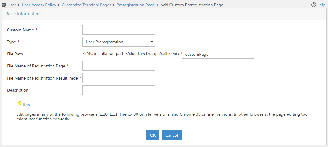
3. Configure the following parameters:
¡ Custom Name—Enter the name of the PC preregistration page set, which must unique among all preregistration page set names.
¡ Type—Select User Preregistration or Guest Preregistration.
¡ File Path—Specify the path where the preregistration page files are stored. By default, the page files are stored in the /client/web/apps/selfservice directory of the IMC installation path. You can save the files to a subdirectory under the default directory.
¡ File Name of Registration Page—Specify the file pathname of the registration page. The file must be in JSP format.
¡ File Name of Registration Result Page—Specify the file pathname of the registration result page. The page file must be in JSP format.
¡ Description—Enter a description for the preregistration page set.
4. Click OK.
UAM auto-populates the file name, file path, and URL of the preregistration page.
Copying a template-based preregistration page set
You can create a new preregistration page by copying an existing template-based preregistration page.
To copy a preregistration page set:
5. Access the PC preregistration page set list page.
6. Click the Copy icon ![]() for a preregistration page set.
for a preregistration page set.
The Copy Custom Preregistration Page opens.
7. Configure the following parameters:
¡ Custom Name—By default, the page is named in the format of copy + original BYOD page set name. You can specify a new name for the preregistration page set. The name must unique among all preregistration page set names.
¡ Type—Cannot be modified.
¡ Description—Specify a description for the preregistration page.
8. Click OK.
UAM auto-populates the file name, file path, and URL of the preregistration page.
Modifying a template-based preregistration page set
You can only modify the description of a template-based preregistration page set.
To modify a preregistration page set:
9. Access the PC preregistration page set list page.
10. Click the Modify
icon ![]() for the
preregistration page set.
for the
preregistration page set.
11. Modify the description of the preregistration page set.
12. Click OK.
Deleting a template-based preregistration page set
You cannot delete a preregistration page set that is being used by the self-service login page.
Deleting a template-based preregistration page from the preregistration page list also deletes the page file from IMC.
To delete a preregistration page set:
13. Access the PC preregistration page set list page.
14. Click the Delete
icon ![]() for the
preregistration page set you want to delete.
for the
preregistration page set you want to delete.
A confirmation dialog box opens.
15. Click OK.
16. Restart IMC to validate the deletion.
Editing a template-based preregistration page
You can edit the preregistration page layout as well as the fields displayed on the page.
To edit a preregistration page:
17. Access the PC preregistration page set list page.
18. Click the Preregistration Page icon ![]() in the Draw column of a preregistration page set.
in the Draw column of a preregistration page set.
The preregistration page is displayed in a drawing canvas.
19. Move your mouse pointer to the middle right of the drawing canvas to display the option menu.
20. Edit the page as needed. For more information, see UAM Terminal Page Customization Guide.
21. Click the Save menu option to save the page.
22. Click the Close menu option to close the drawing canvas.
Previewing a template-based preregistration page
23. Access the PC preregistration page set list page.
24. Click the Preregistration Page icon ![]() in
the Preview column of a preregistration page set.
in
the Preview column of a preregistration page set.
The preview image of the preregistration page opens in a new window.
Publishing a template-based preregistration page
After you finished editing a preregistration page, you must publish the page before using it in the self-service login page.
To publish a template-based preregistration page:
25. Access the PC preregistration page set list page.
26. Click the Preregistration Page icon ![]() in
the Draw column of a preregistration page set.
in
the Draw column of a preregistration page set.
The preregistration page is displayed in a drawing canvas.
27. Move your mouse pointer to the middle right of the drawing canvas to display the option menu.
28. Click the Publish menu option.
UAM automatically saves the page and publish the page.
Managing imported preregistration page sets
You can import external preregistration page sets to UAM as user-defined preregistration page sets.
Imported preregistration page sets have a template name of User Defined.
Because the embedded editing tool of UAM is not compatible with third-party editing software, you cannot edit, preview, or copy an imported preregistration page set. However, UAM allows you to modify and delete an imported preregistration page set.
You must restart IMC to validate an imported preregistration page and make it available to the self-service login page.
Importing an external preregistration page set
1. Access the PC preregistration page set list page.
2. Click Add for the User Defined template.
The Add Custom Preregistration Page opens.
3. Configure the following parameters:
¡ Custom Name—Enter the name of the preregistration page set, which must unique among all preregistration page set names.
¡ Type—Select User Preregistration or Guest Preregistration.
¡ File Path—Specify the path where the preregistration page file is stored. By default, the page file is stored in the /client/web/apps/preregistration/ directory of the IMC installation path. You can save the file to a subdirectory under the default directory.
¡ File Name—Specify the file pathname of the page. The file must be in XHTML format.
|
|
NOTE: You must first create the specified directory in the /client/web/apps/preregistration/ directory of the IMC installation path on the IMC server, and save the preregistration page file to the directory. |
¡ Description—Enter a description for the imported preregistration page set.
4. Click OK.
Modifying an imported preregistration page set
You cannot edit the content of the preregistration page, but you can replace the preregistration page with a new page or change the location where the preregistration page file is saved.
You must restart IMC to validate the modifications made to the page and make the new page available to the self-service login page.
To modify an imported preregistration page set:
5. Access the PC preregistration page set list page.
6. Click the Modify
icon ![]() for a
preregistration page set.
for a
preregistration page set.
The Modify Custom Preregistration Page opens.
7. Modify the parameters except Custom Name and Type for the preregistration page set.
8. Click OK.
Deleting an imported preregistration page set
You cannot delete an imported preregistration page set that is being used by the self-service login page.
Deleting an imported preregistration page set from the preregistration page set list does not delete page file from IMC.
To delete an imported preregistration page set:
9. Access the PC preregistration page set list page.
10. Click the Delete
icon ![]() for the
preregistration page set you want to delete.
for the
preregistration page set you want to delete.
A confirmation dialog box opens.
11. Click OK.
Managing cell phone preregistration page sets
UAM offers basically the same management functions for PC preregistration page sets and cell phone preregistration page sets. For information about managing cell phone portal page sets, see "Managing PC portal page sets."
Table 35 describes the differences between PC portal page sets and cell phone portal page sets. For more information about editing preregistration pages, see UAM Terminal Page Customization Guide.
Table 35 Cell phone preregistration page sets vs. PC preregistration page sets
|
Item |
Cell phone preregistration page |
PC preregistration page |
|
System-defined template |
Four content templates. No blank template. |
Four content templates and one blank template. |
Applying preregistration page sets
Preregistration pages include user preregistration pages and guest preregistration pages.
Applying a user preregistration page set
To apply a user preregistration page set to users, you must enable the display of the User Preregistration link on the self-service login page.
To apply a user preregistration page:
1. Create and publish a user preregistration page, or import an external user preregistration page.
2. Restart IMC in the IMC deployment monitoring agent.
¡ In centralized deployment, restart the jserver process.
¡ In distributed deployment, restart self-service.
3. Modify the self-service login page.
Enable the display of the User Preregistration link, and specify the URL of the link as the user preregistration page created in step 1. For more information, see "Customizing and applying self-service pages."
4. A user can access the user preregistration page by clicking the User Preregistration link on the self-service login page.
Applying guest preregistration page sets
To apply a guest preregistration page set to guest users, you must enable the display of the Guest Preregistration link on the self-service login page.
To apply a guest preregistration page:
1. Create and publish a guest preregistration page, or import an external guest preregistration page.
2. Restart IMC.
3. Modify the self-service login page.
Enable the display of the Guest Preregistration link, and specify the URL of the link as the guest preregistration page created in step 1. For more information, see "Customizing and applying self-service pages."
4. When a user clicks the Guest Preregistration link on the self-service login page, the specified guest preregistration page opens.
Managing and applying BYOD page sets
BYOD pages are divided into PC BYOD pages (designed for PCs and PADs) and cell phone BYOD pages.
This section describes how to manage and apply these two types of BYOD pages.
Managing PC BYOD page sets
In UAM, a BYOD page configuration is referred to as a page set, which includes a page set name, a BYOD page, path and name of the page file, and a description.
Depending on how the BYOD page set is created, BYOD page sets are divided into template-based BYOD page sets and imported BYOD page sets.
· Template-based BYOD page sets—BYOD page sets that are created based on predefined templates.
· Imported BYOD page sets—External BYOD pages that are imported into UAM.
The following sections describe these two types of BYOD pages separately.
Accessing the PC BYOD page list page
1. Click the User tab.
2. From the navigation tree, select User Access Policy > Customize Terminal Pages > BYOD Page.
3. Click the PC tab.
The tab consists of a template area and a BYOD page set list.
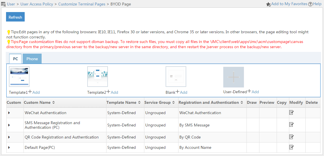
Template area
UAM provides two content templates (Template 1 and Template 2), one blank template, and one user-defined template for creating PC BYOD pages.
¡ Content template—Provides an editable sample PC BYOD page. You can quickly create a BYOD page by editing the template.
¡ Blank template—Allows you to create PC BYOD pages from scratch.
¡ User-Defined template—Allows you to import external BYOD pages to UAM.
BYOD page set list contents
¡ Expand—Click the Expand icon ![]() to expand the BYOD page details area. The
area contains the file pathnames of the registration/login page and the result
page, and a description. Click the Collapse icon
to expand the BYOD page details area. The
area contains the file pathnames of the registration/login page and the result
page, and a description. Click the Collapse icon ![]() to collapse the area.
to collapse the area.
¡ Custom Name—Name of the BYOD page, which must unique among all BYOD page names.
¡ Template Name—Name of the template based on which the BYOD page is created. User-Defined indicates the BYOD page is an external page imported to UAM.
¡ Service Group—Service group to which the BYOD page belongs.
¡ Edit—Click the Registry and Login Page icon ![]() or the Result Page icon
or the Result Page icon ![]() to edit the
registration/login page or result page. This field is empty if the Template Name field displays User Defined.
to edit the
registration/login page or result page. This field is empty if the Template Name field displays User Defined.
¡ Preview—Click the Registry and Login Page icon ![]() or the Result Page icon
or the Result Page icon ![]() to preview the
registration/login page or result page. This field is empty if the Template Name field displays User Defined.
to preview the
registration/login page or result page. This field is empty if the Template Name field displays User Defined.
¡ Copy—Click the Copy icon ![]() to make a new copy of
the BYOD page set. This field
is empty if the Template Name field displays User
Defined.
to make a new copy of
the BYOD page set. This field
is empty if the Template Name field displays User
Defined.
¡ Modify—Click the Modify icon ![]() to modify the BYOD page set.
to modify the BYOD page set.
¡ Delete—Click the Delete icon ![]() to delete the BYOD page set.
to delete the BYOD page set.
Managing template-based BYOD page sets
You can copy, modify, delete, edit, and preview BYOD page sets that are created based on a content template or the blank template.
Adding a template-based BYOD page set
UAM provides two content templates and a blank template.
To add a BYOD page set based on a template:
1. Access the PC BYOD page set list page.
2. Click Add for a content template or the blank template.
The Add Custom BYOD Page opens.
3. Configure the following parameters:
¡ Custom Name—Enter the name of the BYOD page set, which must unique among all BYOD page set names.
¡ Service Group—Select the service group to which the BYOD page set belongs.
¡ Description—Enter a description for the BYOD page set.
4. Click OK.
UAM auto-populates the file name and file path of the BYOD page.
Copying a template-based BYOD page set
You can create a new BYOD page by copying an existing template-based BYOD page set.
To copy a BYOD page set:
1. Access the PC BYOD page set list page.
2. Click the Copy icon ![]() for the BYOD page set.
for the BYOD page set.
The Copy Custom Preregistration Page opens.
3. Configure the following parameters:
¡ Custom Name—By default, the page is named in the format of copy + original page set name. You can specify a new name for the BYOD page set. The name must unique among all BYOD page set names.
¡ Service Group—Cannot be modified.
¡ Description—Specify a description for the BYOD page set.
4. Click OK.
UAM auto-populates the file name and file path of the BYOD page.
Modifying a template-based BYOD page set
You can only modify the description of a template-based BYOD page set.
To modify a template-based BYOD page set:
1. Access the PC BYOD page set list page.
2. Click the Modify
icon ![]() for the BYOD
page set.
for the BYOD
page set.
3. Modify the description of the BYOD page set.
4. Click OK.
Deleting a template-based BYOD page set
You cannot delete a BYOD page set that is being used by a service.
Deleting a template-based BYOD page deletes the page file from IMC.
You must restart IMC to validate the deletion of a BYOD page.
To delete a template-based BYOD page set:
1. Access the PC BYOD page set list page.
2. Click the Delete
icon ![]() for the BYOD
page set.
for the BYOD
page set.
A confirmation dialog box opens.
3. Click OK.
Editing a template-based BYOD page
You can edit the page layout as well as the fields on the page.
To edit a template-based BYOD page:
1. Access the PC BYOD page set list page.
2. Click the Draw BYOD Page icon ![]() in the Draw column of the BYOD page set.
in the Draw column of the BYOD page set.
The BYOD page is displayed in a drawing canvas.
3. Move your mouse pointer to the middle right of the drawing canvas to display the option menu.
4. Edit the page as needed. For more information, see UAM Terminal Page Customization Guide.
5. Click the Save menu option to save the BYOD page.
6. Click the Close menu option to close the drawing canvas.
Previewing a template-based BYOD page
1. Access the PC BYOD page set list page.
2. Click the Preview BYOD Page icon ![]() in
the Preview column of a BYOD page set.
in
the Preview column of a BYOD page set.
The preview image of the BYOD page opens in a new window.
Publishing a template-based BYOD page
After you finished editing a BYOD page, you must publish the page and restart IMC to make the page available to UAM services.
To publish a BYOD page:
1. Access the PC BYOD page set list page.
2. Click the Draw BYOD Page icon ![]() in the Draw column of a BYOD page set.
in the Draw column of a BYOD page set.
The BYOD page is displayed in a drawing canvas.
3. Move your mouse pointer to the middle right of the drawing canvas to display the option menu.
4. Click the Publish menu option.
UAM automatically saves and publishes the page.
5. Restart IMC to make the page available to other UAM services.
Managing imported BYOD page sets
You can import external BYOD page sets to UAM as user-defined BYOD page sets.
UAM identifies an imported BYOD page set with a template name of User Defined.
Because the embedded editing tool of UAM is not compatible with third-party editing software, you cannot edit, preview, or copy an imported BYOD page set. However, UAM allows you to modify and delete an imported BYOD page set.
After importing a BYOD page, you must restart IMC to make the page available to services.
Importing an external BYOD page set
1. Access the PC BYOD page set list page.
2. Click Add for the User-Defined template.
The Add Custom BYOD Page opens.
3. Configure the following parameters:
¡ Custom Name—Enter the name of the BYOD page set, which must unique among all BYOD page set names.
¡ Service Group—Select the service group to which the BYOD page set belongs.
¡ Description—Enter a description for the imported BYOD page set.
4. Click OK.
5. Restart IMC to validate the page.
Modifying an imported BYOD page set
You cannot edit the content of an imported BYOD page, but you can replace the BYOD page contained in the BYOD page set or change the location where the BYOD page file is saved.
You must restart IMC to validate the modifications made to the page and make the page available to services.
To modify an imported BYOD page set:
1. Access the PC BYOD page set list page.
2. Click the Modify
icon ![]() for the
imported BYOD page set.
for the
imported BYOD page set.
The Modify Custom BYOD Page opens.
3. Modify the parameters except Custom Name and Type for the BYOD page set.
4. Click OK.
Deleting an imported BYOD page set
You cannot delete an imported BYOD page set that is being used by a service
Deleting an imported BYOD page set does not delete page file from IMC.
To delete an imported BYOD page set:
1. Access the PC BYOD page set list page.
2. Click the Delete
icon ![]() for the BYOD
page set you want to delete.
for the BYOD
page set you want to delete.
A confirmation dialog box opens.
3. Click OK.
Managing cell phone BYOD page sets
UAM offers basically the same management functions for PC BYOD page sets and cell phone BYOD page sets. For information about managing cell phone BYOD page sets, see "Managing PC BYOD page sets."
Table 36 describes the differences between cell phone BYOD page sets and PC BYOD page sets. For information about editing BYOD pages, see UAM Terminal Page Customization Guide.
Table 36 Cell phone BYOD page sets vs. PC BYOD page sets
|
Comparison item |
Cell phone BYOD page |
PC BYOD page |
|
System-defined template |
Two content templates. No blank template. |
Two content templates and one blank template. |
|
Page editing |
Users can edit existing areas but cannot create new areas. |
Users can edit existing areas and create new areas. |
Applying a BYOD page to users
1. Create or import BYOD pages and publish the pages.
2. Restart IMC.
3. In UAM page push policy configuration, perform the following tasks:
¡ Select MAC for Authentication Method.
¡ Assign a BYOD page set to the service as the Default BYOD Page.
¡ Add subpolicies, and assign BYOD page sets to different access scenarios in the service.
4. When a user who uses the service accesses the BYOD network, UAM displays the BYOD page that is assigned to the user's matching access scenario. If the user matches no access scenario, UAM displays the default BYOD page set to the user.
For more information configuring page push policies, see "Configuring page push policies."
Customizing and applying self-service pages
UAM provides predefined self-service login pages. You can edit these pages, but you cannot add or import new self-service login pages.
UAM allows you to customize the PC user login page, PC guest login page, mobile device login page, mobile device guest approval page, and PC menus. The customized PC menus are displayed on the navigation tree of the self-service center for PCs.
Modifying the self-service login page for PCs
1. Click the User tab.
2. From the navigation tree, select User Access Policy > Customize Terminal Pages > Self-Service Page.
3. Click the PC Login Page tab.
4. Configure basic information:
a. Click the Modify
icon ![]() for a
field to enter editor mode.
for a
field to enter editor mode.
b. Enter the content and remarks of the field. The field content will be displayed on the self-service login page.
c. In the Modify column,
click ![]() or
or ![]() to save or cancel
your modification.
to save or cancel
your modification.
Figure 119 Configuring basic information
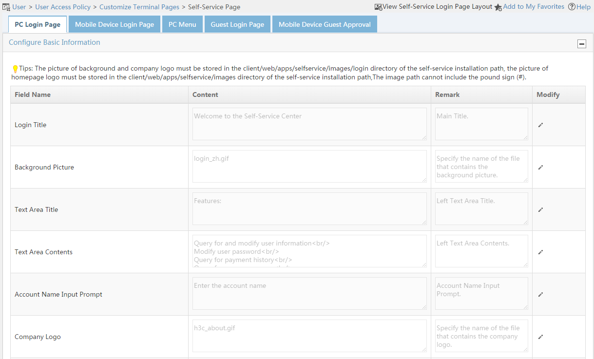
Figure 119 is a sample self-service login page. From this page, you can view where the basic information fields are displayed.
¡ Login Title—Displayed at (2).
¡ Background Picture—Displayed at (5). The picture must be stored in the /client/web/apps/selfservice/images/login/ directory of the self-service installation path on the server.
¡ Text Area Title—Displayed at (3).
¡ Text Area Title—Displayed at (4).
¡ Account Name Input Prompt—Displayed at (6). The prompt message is displayed when you place your cursor over the Account Name field on the self-service login page.
¡ Company Logo—Displayed at (1). The picture must be stored in the /client/web/apps/selfservice/images/login/ directory of the self-service installation path on the server.
¡ Homepage Logo—Logo displayed on the self-service homepage. The picture must be stored in the /client/web/apps/selfservice/images/login/ directory of the self-service installation path on the server.
¡ Company Website—URL that you are redirected to after clicking the company logo (1).
¡ Complete Copyright Information—Displayed at (7).
Figure 120 Self-service homepage
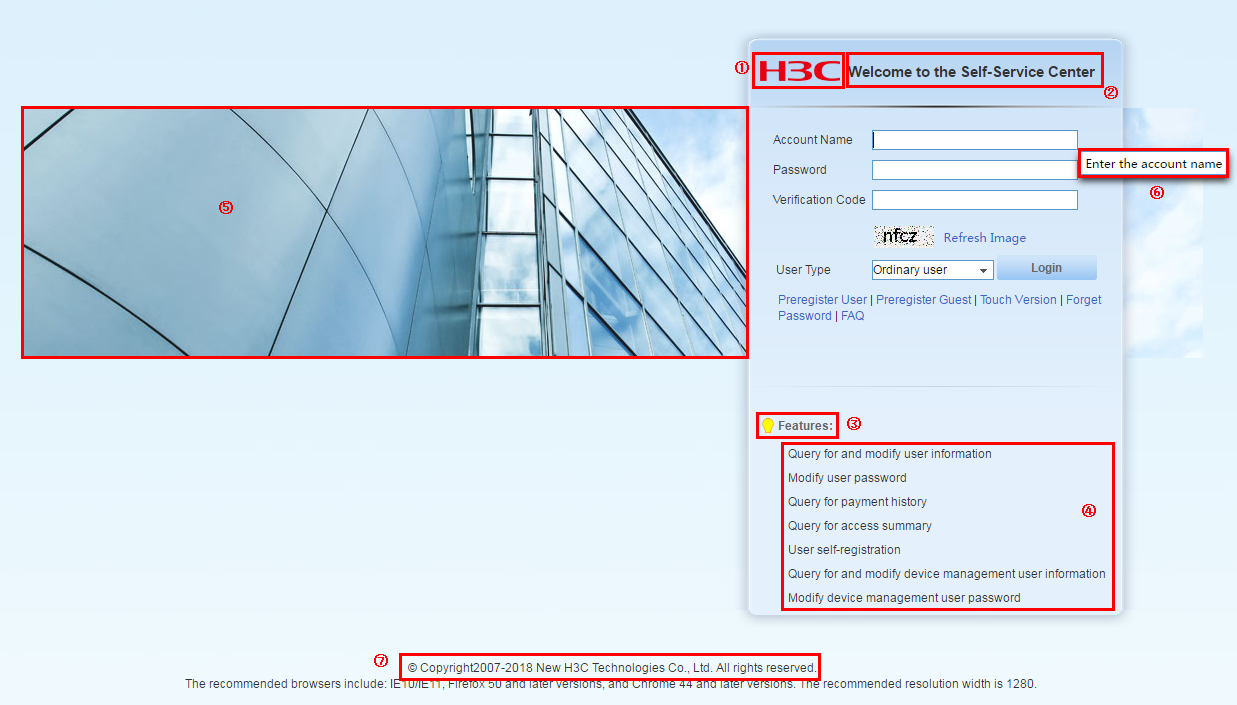
5. Configure links:
a. Click the Modify
icon ![]() for a
link to enter editor mode. Figure 120
shows the positions of the links on the self-service login page.
for a
link to enter editor mode. Figure 120
shows the positions of the links on the self-service login page.
Figure 121 Links on the self-service login page for PCs
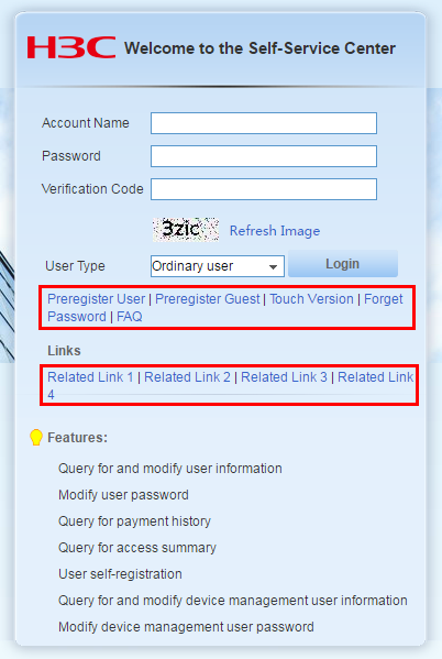
b. Edit the following information for a link:
- Display Name—Enter the display name of the link.
- URL—Specify a URL for the link, except Forget Password, FAQ, and Touch Version links. For information about configuring user and guest preregistration pages, see "Managing and applying preregistration page sets."
- Display—Select the option to display the link on the self-service login page.
c. In the Modify
column, click ![]() or
or ![]() to save or cancel your configuration.
to save or cancel your configuration.
When the Guest Preregister parameter is disabled in the guest service parameters, the Display parameter for the Guest Preregister link is disabled and cannot be modified. For more information, see "Configuring guest service parameters."
Modifying the self-service login page for mobile devices
1. Click the User tab.
2. From the navigation tree, select User Access Policy > Customize Terminal Pages > Self-Service Page.
3. Click the Mobile Device Login Page tab.
4. Configure basic information:
a. Click the Modify
icon ![]() for a
field to enter editor mode.
for a
field to enter editor mode.
b. Enter the content and remarks of the field. The field content will be displayed on the self-service login page.
c. In the Modify column,
click ![]() or
or ![]() to save or cancel
your modification.
to save or cancel
your modification.
Figure 122 Configuring basic information
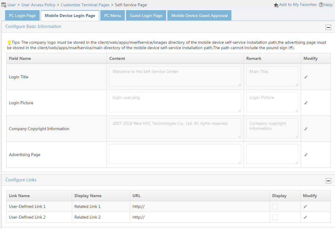
Figure 122 is a sample mobile device self-service login page. From this page, you can view where the basic information fields are displayed.
¡ Login Title—Displayed at (1).
¡ Login Picture—Displayed at (2). The picture must be stored in the /client/web/apps/mselfservice/images directory of the self-service installation path on the server.
¡ Company Copyright Information—Displayed at (3).
¡ Advertising page—Displayed at Figure 123. The advertising page opens immediately after the user login. The page must be in XHTML format and stored in the /client/web/apps/mselfservice/main directory of the self-service installation path on the server.
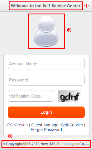

5. Configure links:
a. Click the Modify
icon ![]() for a
link to enter editor mode. Figure 124
shows the positions of the links on the self-service login page.
for a
link to enter editor mode. Figure 124
shows the positions of the links on the self-service login page.
Figure 125 Links on the self-service login page for mobile devices
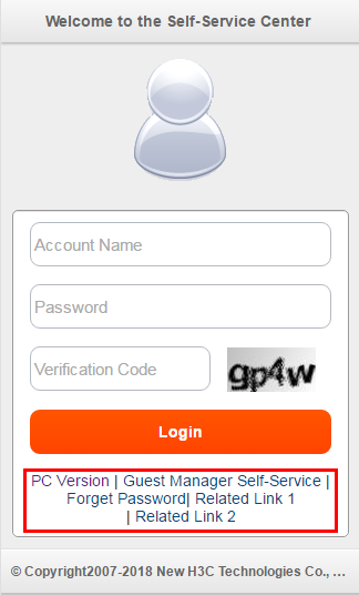
b. Edit the following information for a link:
- Display Name—Enter the display name of the link.
- URL—Specify a URL for the link.
- Display—Select the option to display the link on the self-service login page.
c. In the Modify
column, click ![]() or
or ![]() to save or cancel your configuration.
to save or cancel your configuration.
Configuring PC menu customization policies
PC menu customization policies enable the self-service center to display different custom navigation trees for PC users based on the user group. The user groups manage user privileges hierarchically.
One user group can be associated with only one PC menu customization policy. One PC menu customization policy can be associated with multiple user groups.
Menu customization policies include the following:
· Default policy—When a user group is not associated with any menu customization policy, the default policy applies to the user group. The default policy can be modified but cannot be deleted.
· Self-defined policies—Used to customize menus in the self-service center for PCs based on the user group.
Accessing the menu customization policy list page
1. Click the User tab.
2. From the navigation tree, select User Access Policy > Customize Terminal Pages > Self-Service Page.
3. Click the PC Menu tab.
Menu customization policy list contents
¡ Policy Name—Name of the menu customization policy.
¡ Modify—Click the Modify icon ![]() to modify the menu customization policy.
to modify the menu customization policy.
¡ Delete—Click the Delete icon ![]() to delete the menu
customization policy.
to delete the menu
customization policy.
Querying menu customization policies
1. Access the menu customization policy list.
2. In the Query PC Menu Customization Policies area, specify one or more of the following query criteria:
¡ Policy Name—Enter a partial or complete name of the menu customization policy.
¡ User Group—Click the User Group icon ![]() next to this field, select a user group, and click OK.
next to this field, select a user group, and click OK.
The query ignores empty fields.
3. Click Query. The list shows all menu customization policies that match the query criteria.
Click Reset to clear the query criteria. The list shows all menu customization policies in UAM.
Adding a menu customization policy
1. On the menu customization policy list, click Add.
2. In the Policy Name field, enter a unique menu customization policy name.
3. In the Menu List area, select menus as needed.
Perform the following actions to aid your selection:
¡ Click the Expand all icon to expand all menus.
¡ Click the Fold all icon to collapse all menus.
¡ Click the Select all icon to select all menus in the list.
¡ Click the Clear all icon to clear all selected menus.
The navigation tree includes the following primary menus:
¡ User Information (Level-2 menu includes Query User Information, Update User Information, and Modify Password. Update User Information allows users to modify personal information after logging in to the self-service center. Operators can customize the information that can be modified by selecting the corresponding options.)
¡ Asset Maintenance (displayed only when the EAD component is installed)
¡ Self-Service Lobby
¡ Trouble Management
¡ Guest Management
¡ Endpoint Management
|
|
NOTE: To display the Guest Management menu in the self-service center, make sure the following conditions are met: · The menu customization policy includes the Guest Management menu and its submenus. · Guest managers belong to the user group associated with the menu customization policy. · A guest manager logs in to the self-service center. |
4. In the User Group List area, select user groups to be associated with the menu customization policy. You can click the Expand all or Fold all icon to expand or fold all menus.
With the Include Parent and Subgroups option selected, selecting a user group also selects its parent group and subgroups.
5. Click OK.
The new menu customization policy is added to the list.
Modifying a menu customization policy
1. On the menu customization policy list, click the Modify icon ![]() for a policy.
for a policy.
2. Modify the policy parameters. For more information, see "Adding a menu customization policy."
3. Click OK.
Deleting a menu customization policy
1. On the menu customization policy list, click the Delete icon ![]() for a policy.
for a policy.
A confirmation dialog box opens.
2. Click OK.
Modifying the Guest Center login page for PCs
1. Click the User tab.
2. From the navigation tree, select User Access Policy > Customize Terminal Pages > Self-Service Page.
3. Click the Guest Login Page tab.
4. Configure basic information:
a. Click the Modify
icon ![]() for a field to enter editor mode.
for a field to enter editor mode.
b. Enter the content and remarks of the field. The field content will be displayed on the self-service login page.
c. In the Modify column,
click ![]() or
or ![]() to save or cancel your modification.
to save or cancel your modification.
Figure 126 Configuring basic information
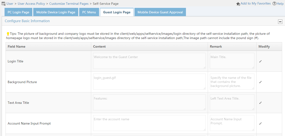
Figure 126 is a sample guest login page. From this page, you can view where the basic information fields are displayed.
¡ Login Title—Displayed at (2).
¡ Background Picture—Displayed at (5). The picture must be stored in the /client/web/apps/selfservice/images/login directory of the self-service center installation path on the server.
¡ Text Area Title—Displayed at (3).
¡ Text Area Contents—Displayed at (4).
¡ Account Name Input Prompt—Displayed at (6). The prompt message is displayed when you point to the Account Name field on the self-service login page.
¡ Company Logo—Displayed at (1). The picture must be stored in the /client/web/apps/selfservice/images/login directory of the self-service center installation path on the server.
¡ Homepage Logo—Logo displayed on the self-service home page, as shown in Figure 127. The picture must be stored in the /client/web/apps/selfservice/images directory of the self-service center installation path on the server.
¡ Company Website—URL that you are redirected to after clicking the company logo (1).
¡ Complete Copyright Information—Displayed at (7).
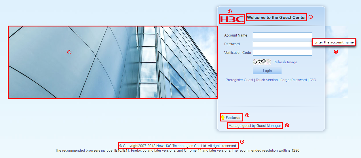
Figure 128 Self-service homepage
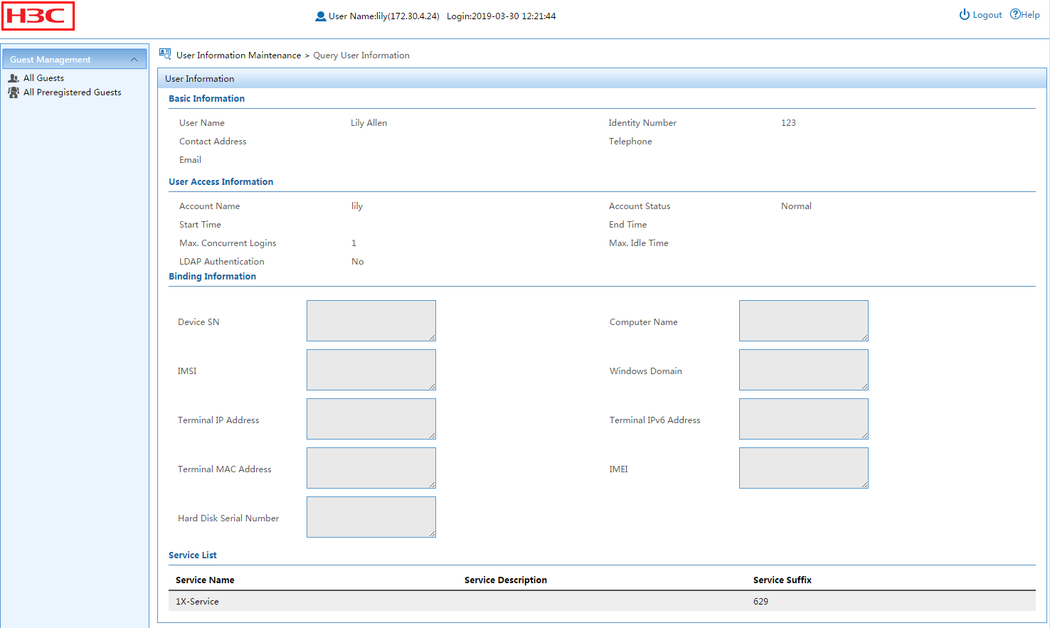
5. Configure links:
a. Click the Modify
icon ![]() for a
link to enter editor mode. Figure 128
shows the positions of the links on the self-service login page.
for a
link to enter editor mode. Figure 128
shows the positions of the links on the self-service login page.
Figure 129 Editing links of the Guest Center login page for PCs
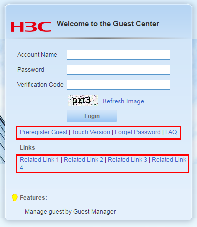
a. Edit the following information for a link:
- Display Name—Enter the display name of the link.
- URL—Specify a URL for the link, except Forget Password, FAQ, and Touch Version links. For information about configuring user and guest preregistration pages, see "Managing and applying preregistration page sets."
- Display—Select the option to display the link on the self-service login page.
b. In the Modify
column, click ![]() or
or ![]() to save or cancel your configuration.
to save or cancel your configuration.
When the Guest Preregister parameter is disabled in the guest service parameters, the Display parameter of the Guest Preregister link is disabled and cannot be modified. For more information, see "Configuring guest service parameters."
Customizing the guest approval page for mobile devices
1. Click the User tab.
2. From the navigation tree, select User Access Policy > Customize Terminal Pages > Self-Service Page.
3. Click the Mobile Device Guest Approval tab.
4. Customize approval items for mobile device guests.
The following customization items are required and have been selected by default:
¡ Guest Name
¡ Identity Number
¡ Account Name
The following customization items are optional:
¡ Telephone
¡ Contact Address
¡ Comments
¡ Visited Department
¡ Receptionist
¡ Device SN
¡ Port
¡ Outer VLAN ID
¡ VLAN ID/Inner VLAN ID
¡ User SSID
¡ Device IP
¡ Computer Name
¡ IMSI
¡ Windows Domain
¡ Terminal IP Address
¡ Terminal IPv6 Address
¡ Terminal MAC Address
5. Click OK.
Figure 130 Customizing the approval items
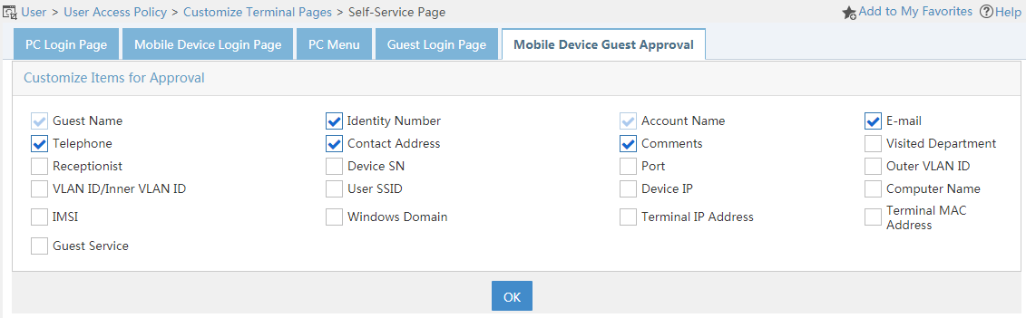
Figure 131 Mobile device guest approval page
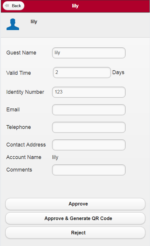
Figure 132 Mobile device guest regular registration page
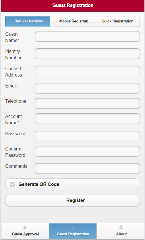
Configuring page push policies
A page push policy allows UAM to push different authentication pages to endpoint users under various conditions. If an authentication page provides guest registration, the page push policy can be associated with a guest policy to control the registration process. The two policies are associated using a guest group. For information about configuring guest policies, see "Managing guest policies." The page pushing processes for portal authentication and MAC authentication are shown in Figure 132 and Figure 133.
Figure 133 Page pushing process for portal users
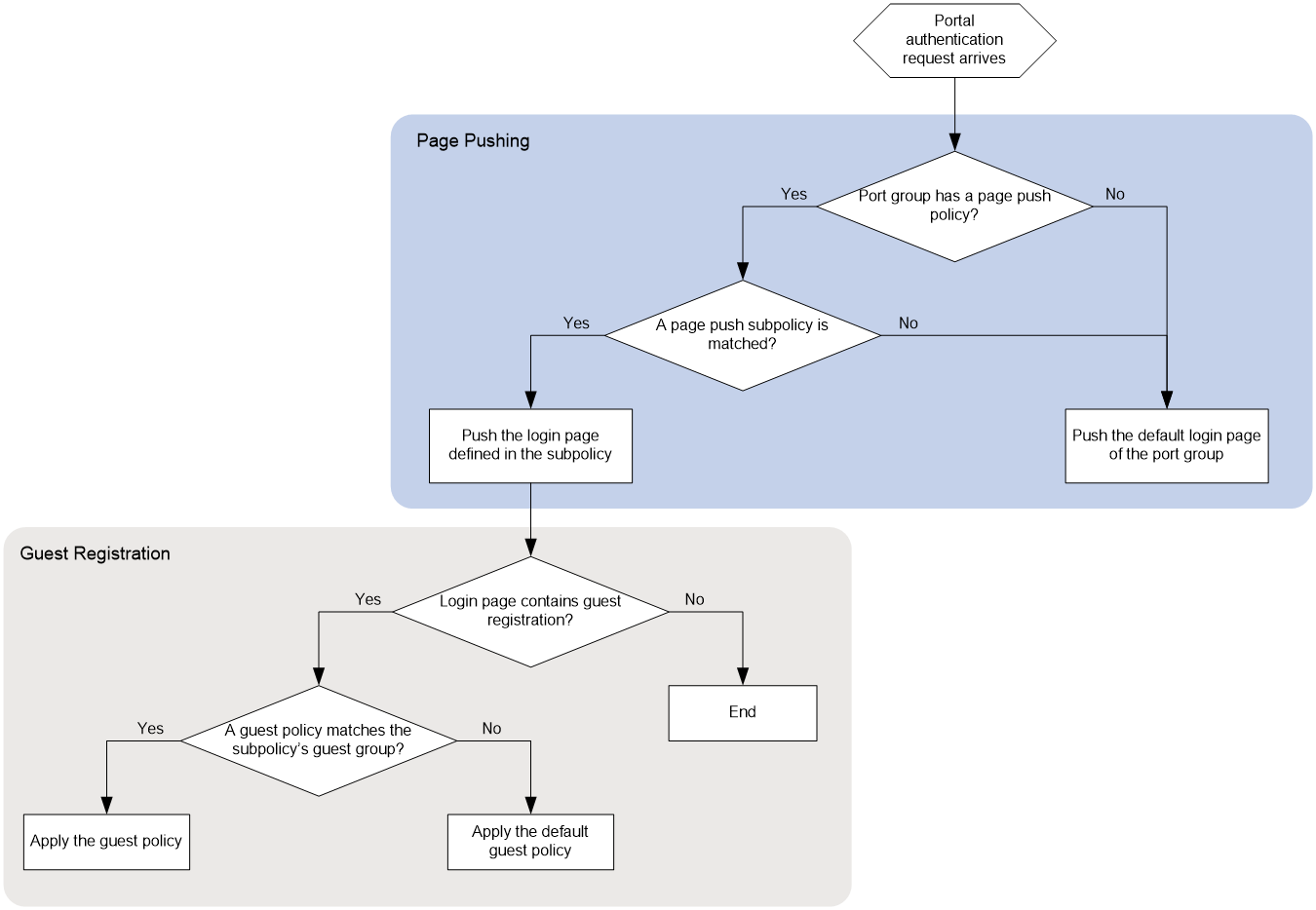
Figure 134 Page pushing process for BYOD users
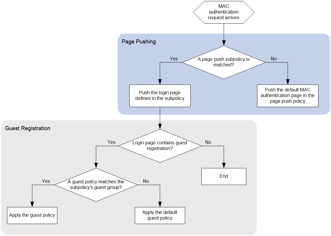
Accessing the page push policy list page
1. Click the User tab.
2. From the navigation tree, select User Access Policy > Page Push Policy.
The list includes all page push policies.
Page push policy list contents
¡ Policy Name—Name of the page push policy.
¡ Service Group—Service group to which the page push policy belongs.
¡ Authentication Method—User authentication method to which the page push policy applies. Options are Portal and MAC.
¡ Modify—Click the Modify icon ![]() to modify the page push policy.
to modify the page push policy.
¡ Delete—Click the Delete icon ![]() to delete the page
push policy.
to delete the page
push policy.
Viewing page push policy details
1. Access the page push policy list.
2. Click the name of a page push policy.
The page displays detailed information about the page push policy.
Basic Information
¡ Policy Name—Name of the page push policy.
¡ Service Group—Service group that the page push policy belongs to.
¡ Authentication Method—User authentication method that the page push policy applies to. Options are Portal and MAC.
¡ Default Authentication Page—Default authentication page for users who match none of the subpolicies contained in the policy. This parameter is displayed only when the authentication method is MAC.
¡ Description—Description of the page push policy.
Page Push Subpolicy List
¡ Subpolicy Name—Name of the subpolicy.
¡ Login Page—Authentication page that is pushed to matching users.
¡ Guest Group—Guest group the matching users belong to for guest registration. The guest group is associated with a guest policy. For information about the guest policy, see "Managing guest policies."
¡ Guest Manager—Guest manager of the guests registered by the matching users.
¡ Details—Click the Details icon ![]() to view the detailed information of the subpolicy. Details include
the subpolicy name, conditions,
and policy strategy.
to view the detailed information of the subpolicy. Details include
the subpolicy name, conditions,
and policy strategy.
Conditions include different groups and the HTTP user agent character. The subpolicy is matched only when all conditions are matched.
The strategy includes the login page, guest group, and guest manager.
Adding a page push policy
1. On the page push policy list, click Add.
2. In the Basic Information area, configure the following parameters:
¡ Policy Name—Enter a unique name for the page push policy.
¡ Service Group—Select a service group that the page push policy belongs to. Options are Ungrouped and all existing service groups in UAM.
¡ Authentication Method—Select an authentication method from the list. Options are Portal and MAC. Only one page push policy can be configured for MAC authentication. If UAM already has a page push policy for MAC authentication, the Authentication Method list of the new policy is unavailable and automatically populated with Portal.
¡ Default Authentication Page—Select a page from the list as the default authentication page for users who match none of the subpolicies in the policy. This parameter is displayed only when the authentication method is MAC. For information about customizing BYOD pages, see "Managing and applying BYOD page sets."
¡ Description—Enter a description for the page push policy.
3. In the Page Push Subpolicy List area, click Add.
4. In the Condition area, configure the following parameters:
¡ Subpolicy Name—Enter the name of the subpolicy. Make sure subpolicies use different names in the page push policy.
¡ Access Location Group—Select an access location group from the list. This condition is met if users are connected to an access device in the selected group. For information about adding an access location group, see "Configuring access location groups."
¡ SSID Group—Select an SSID group from the list. This condition is met if users are connected to a SSID in the selected group. For information about adding an SSID group, see "Configuring SSID groups."
¡ AP Group—Select an AP group from the list. This condition is met if users are connected to an AP in the selected group. For information about adding an AP group, see "Configuring AP groups."
¡ Endpoint IP Group—Select an endpoint IP group from the list. This condition is met if the IP address of user endpoints belongs to the selected group. For information about adding an endpoint IP group, see "Configuring endpoint IP groups."
¡ Endpoint MAC Group—Select an endpoint MAC group from the list. This condition is met if the MAC address of user endpoints belongs to the selected group. For information about adding an endpoint MAC group, see "Configuring endpoint MAC groups."
¡ Endpoint Vendor Group—Select an endpoint vendor group from the list. This condition is met if the vendor of user endpoints belongs to the selected group. For information about adding an endpoint vendor group, see "Configuring endpoint vendor groups."
¡ Endpoint OS Group—Select an endpoint OS group from the list. This condition is met if the OS of user endpoints belongs to the selected group. For information about adding an endpoint OS group, see "Configuring endpoint OS groups."
¡ Endpoint Type Group—Select an endpoint type group from the list. This condition is met if the type of user endpoints belongs to the selected group. For information about adding an endpoint type group, see "Configuring endpoint type groups."
¡ Access Period Policy—Select an access period policy from the list. For information about adding an access period policy, see "Configuring access policies."
¡ HTTP User Agent Character—Enter an HTTP user agent character.
|
|
TIP: Use a sniffer to obtain the User-Agent value in HTTP packets and configure the HTTP user agent character based on the value. For example, the User-Agent value of an iPad user accessing from the Safari browser is Mozilla/5.0(iPad; U; CPU iPhone OS 3_2 like Mac OS X; en-us) AppleWebKit/531.21.10 (KHTML, like Gecko) Version/4.0.4 Mobile/7B314 Safari/531.21.10. Configure the HTTP user agent character as iPad&&like Mac OS X, where && indicates the AND operation. |
5. In the Strategy area, configure the following parameters:
¡ Login Page—Select a login page for users who match the subpolicy. Options in the list vary with the authentication method of the policy. If the authentication method is portal, the list includes all existing portal pages. If the authentication method is MAC, the list includes all exiting BYOD pages. For information about customizing portal pages and BYOD pages, see "Managing and applying portal page sets" and "Managing and applying BYOD page sets."
¡ Guest Group—Click
the Select User Group icon ![]() to select a group for guest
registration. If a user matches the subpolicy, all guests registered by the
user are controlled by the guest policy assigned to the guest group. For
information about the guest
policy, see "Managing guest policies."
to select a group for guest
registration. If a user matches the subpolicy, all guests registered by the
user are controlled by the guest policy assigned to the guest group. For
information about the guest
policy, see "Managing guest policies."
¡ Guest Manager—Select a guest manager for the guests registered by a matching user. For information about guest manager, see "Managing guest managers in UAM."
6. Click OK.
The subpolicy is added to the subpolicy list.
7. Repeat steps 1 through 6 to add more subpolicies.
8. Click the Move up icon ![]() or Move down icon
or Move down icon ![]() for a subpolicy to adjust its priority.
for a subpolicy to adjust its priority.
The subpolicy list is sorted in descending order of priority. When a user matches more than one subpolicy, UAM applies the subpolicy of the highest priority.
9. Click the Modify icon ![]() to modify a subpolicy.
to modify a subpolicy.
10. Click the Delete icon ![]() for an undesired subpolicy to delete it.
for an undesired subpolicy to delete it.
11. Click OK.
The new page push policy is added to the list.
Modifying a page push policy
1. On the page push policy list, click the Modify icon ![]() for a policy.
for a policy.
2. Modify parameters for the policy except for the service group and authentication method. For more information, see "Adding a page push policy."
3. Click OK.
Deleting a page push policy
A page push policy cannot be deleted when it is assigned to a port group.
To delete a page push policy:
1. On the page push policy list, click the Delete icon ![]() for a policy.
for a policy.
A confirmation dialog box opens.
2. Click OK.
Monitoring and auditing
UAM offers the following monitoring and auditing functions:
· Online user management
· Log analysis
· Data export
Network administrators can use UAM monitoring and auditing functions to monitor online user behavior, and to analyze statistics to improve network performance and security.
Managing online users
Online users include local online users and roaming online users:
· Local online users—Refer to users whose home UAM is the current UAM system.
· Roaming online users—Refer to users whose home UAM is not the current UAM system.
UAM supports the following online user categories:
· Local—Allows you to view and manage all local online users.
· Roaming—Allows you to view and manage all roaming online users.
· By Device—Allows you to view and manage local online users on each device.
Managing local online users
Accessing the local online user list page
1. Click the User tab.
2. From the navigation tree, select Access User > Online Users.
3. Click the Local tab.
The list includes all local online users.
Point to the Expand icon ![]() next to Online Users to
display all user groups. Select a user group to display all local online users in
the user group.
next to Online Users to
display all user groups. Select a user group to display all local online users in
the user group.
Local online user list contents
¡ Account Name—Access account name. Click the account name to view its details. For more information about access users, see "Viewing ordinary access user details."
¡ Login Name—Login user name that the access device sends to UAM for the online user.
A login name can be the same as the account name or in the format account-name@service-suffix. An access account can have multiple services, including one service that has no suffix and multiple services with unique service suffixes.
If an account name with a service suffix is used, the policies associated with the service suffix apply to the online user. If only the account name is used, the policies associated with the service that has no suffix apply to the online user.
¡ User Name—Platform user name for the access account. Every access account must have a user name in the IMC platform, but the access account name can be different than the platform user name.
¡ Service Name—Service assigned to the user. Click the service name to view its details. For more information, see "Viewing access service details."
¡ Login Time—Date and time when the user was logged in, in the format YYYY-MM-DD hh:mm:ss.
¡ Online Duration—Duration (in seconds) that the user has been online.
¡ Device IP—IPv4 or IPv6 address of the access device for the user. Click the device IP to view detailed information about the access device. For more information, see HPE Intelligent Management Center v7.3 Enterprise and Standard Platform Administrator Guide.
¡ User IP Address—IPv4 address of the user.
¡ Security Status—Security status of the user. It shows whether the security check is performed and the check result. This parameter is displayed only when the EAD component is installed. For more information about security status, see HPE Intelligent Management Center v7.3 EAD Security Policy Administrator Guide.
¡ Client Customization Time—Time when the client used by the user was customized.
¡ Operation—Click
the Operation icon ![]() to display the
operation menu that includes the following options:
to display the
operation menu that includes the following options:
- Details—Click Details to view detailed information about the online user.
- Add to Blacklist—Click Add to Blacklist to add the online user to the blacklist. This option is displayed only when the online user is not added to the blacklist.
- Release from Blacklist—Click Release from Blacklist to delete the online user from the blacklist. This option is displayed only when the online user has been added to the blacklist.
¡ Click Refresh to update the online user list.
Performing a basic query for local online users
1. Access the local online user list page.
2. Click Basic Query at the upper right of the page.
If Advanced Query is at the upper right of the page, you are already in basic query mode. Skip this step.
3. In the Query Online Users area, specify one or more of the following query criteria:
¡ Account Name—Enter a partial or complete access account name string. For example, if you enter x, all account names that contain x are matched.
¡ User Group—Click the Select User Group icon ![]() to select a user group
in the Select User Group window that opens. You can
select only one user group.
to select a user group
in the Select User Group window that opens. You can
select only one user group.
The query ignores empty fields.
4. Click Query.
The list includes all local online users that match the query criteria.
5. To clear the query criteria, click Reset.
The list includes all local online users in UAM.
Performing an advanced query for local online users
1. Access the local online user list page.
2. Click Advanced Query at the upper right of the page.
If Basic Query is at the upper right of the page, you are already in advanced query mode. Skip this step.
3. In the Query Online Users area, specify one or more of the following query criteria:
¡ Account Name—Enter a partial or complete access account name string. For example, if you enter x, all account names that contain x are matched.
¡ User Name—Enter a partial or complete platform user name string. For example, if you enter y, all user names that contain y are matched.
¡ User Group—Click the Select User Group icon ![]() to select a user group in the Select User Group window. You
can select only one user group.
to select a user group in the Select User Group window. You
can select only one user group.
¡ Service Name—Select a service from the service list.
¡ Login Start Date & Time/Login End Date & Time—Set a login time
range or click the Calendar icon ![]() to select one. The date and time settings must be in the format
YYYY-MM-DD hh:mm.
to select one. The date and time settings must be in the format
YYYY-MM-DD hh:mm.
¡ Device IP Address Range From/To—Enter an IPv4 address range to match access devices. Enter a complete IPv4 address in each field. The displayed IPv4 addresses are the IPv4 addresses that the matching access devices were added with to UAM and might differ from the IPv4 addresses being used.
¡ Device IPv6 Address Range From/To—Enter an IPv6 address range to match access devices. Enter a complete IPv6 address or an IPv6 address in compressed format in each field. The field does not support a partial IPv6 address. The displayed IPv6 addresses are the IPv6 addresses that the matching access devices were added with to UAM and might differ from the IPv6 addresses being used.
¡ Device NAT IP Address From/To—Enter a range of NAT translated IPv4 addresses for access devices. Enter a complete IPv4 address in each field.
¡ Port—Enter the index of a port that the access device uses to connect to an online user. This index does not include the chassis slot number or sub-slot number. For example, the port displays 3 for both interface numbers 1/0/3 and 2/0/3.
¡ VLAN ID/Inner VLAN ID—Enter a VLAN ID or inner VLAN ID to match online users in the VLAN. UAM supports only an exact match for this field.
¡ Outer VLAN ID—Enter an outer VLAN ID to match online users assigned to this outer VLAN. UAM supports only an exact match for this field.
¡ User SSID—Enter an SSID string. For example, if you enter a, all SSIDs that contain a are matched.
¡ Computer Name—Enter a partial or complete computer name string. For example, if you enter a, all computer names that contain a are matched.
¡ Suspend Duration—Enter an idle duration to match online users that have been idle for at least this duration.
¡ Traffic Status—Select an alarm state for the user traffic. This field is displayed only when the EAD component is installed. For more information about traffic status, see HPE Intelligent Management Center v7.3 EAD Security Policy Administrator Guide.
¡ Device ACL—Enter the device ACL that is deployed to the access device of the user by UAM or the policy server. This field is displayed only when the EAD component is installed. For more information about device ACLs, see HPE Intelligent Management Center v7.3 EAD Security Policy Administrator Guide.
¡ Security Status—Select a security state from the list. This field is displayed only when the EAD component is installed. For more information about security status, see HPE Intelligent Management Center v7.3 EAD Security Policy Administrator Guide.
¡ Client Version—Select an iNode client version from the list. This list includes all iNode client versions used by current online users.
¡ Client Language—Select an iNode client language from the list, which includes all languages used by current online users.
¡ User IP Address Range From/To—Enter an IP address range to match online users. Enter a complete IPv4 address in each field.
¡ User MAC Address—Enter a partial or complete MAC address string to match online users. The string is in the format XXXX-XXXX-XXXX, XX-XX-XX-XX-XX-XX, or XX:XX:XX:XX:XX:XX. For example, if you enter AA-BB, all MAC addresses that contain AA-BB are matched.
¡ User IPv6 Address—Enter a partial or complete IPv6 address to match online users. For example, if you enter E241:AD12, all IPv6 addresses that contain E241:AD12 are matched.
¡ OS Version—Enter a partial or complete operating system string to match specific operating systems. For example, if you enter Windows, all OS versions that contain Windows are matched.
¡ Client OS Kernel Version—Enter a partial or complete computer OS kernel version string. For example, if you enter NT 6, all computer kernel versions that contain NT 6 are matched.
¡ Client Customization Time From/To—Set a time range to match clients customized within this specific
time range. Enter a time range or click the Calendar icon ![]() to select one.
The date and time settings must be in the format YYYY-MM-DD hh:mm.
to select one.
The date and time settings must be in the format YYYY-MM-DD hh:mm.
¡ Device SN—Enter a partial or complete device sequence number to match access devices. For example, if you enter EF, all device sequence numbers that contain EF are matched.
¡ Deploy VLAN—Enter the ID or name of the VLAN used by the online user.
¡ Windows Domain—Enter a partial or complete Windows domain name bound to the computer used by the online user. For example, if you enter a, all Windows domain names that contain a are matched.
¡ IMSI—Enter a partial or complete IMSI number of the endpoint used by the online user. For example, enter px to match all IMSI numbers that contain px.
¡ Endpoint Type—Enter a partial or complete type of the endpoint used by the online user. For example, enter pc to match all endpoint types that contain pc.
¡ Endpoint Vendor—Enter a partial or complete vendor name of the endpoint used by the online user. For example, enter hp to match all endpoint vendors that contain hp.
¡ Endpoint OS—Enter a partial or complete OS name of the endpoint used by the online user. For example, enter win to match all endpoint OSs that contain win.
¡ NAS ID—Enter a partial or complete NAS ID of the access device connected to the online user. For example, enter sw to match all NAS IDs that contain sw.
The query ignores empty fields.
4. Click Query.
The list includes all the local online users that match the query criteria.
5. To clear the query criteria, click Reset.
The list includes all local online users in UAM.
Viewing local online user details
1. Access the local online user list page.
2. On the local online
user list, click the Operation icon ![]() for an online user, and select Details from the menu.
for an online user, and select Details from the menu.
Detailed information includes Basic information and Access information. The page also includes an Action menu on the right.
Basic information
¡ Account Name—Access account name of the user. Click the account name to view its details. For more information, see "Viewing ordinary access user details."
¡ User Name—Name of the platform user to which the access user account is attached.
¡ Login Name—Login user name that the access device sends to UAM for the user. A login user name can be the same as the account name or in the format accountname@service-suffix.
¡ Service Name—Service assigned to the user.
¡ User Group—Group to which the user belongs.
¡ Security Policy—Security policy that is assigned to the user. This parameter is displayed only when the EAD component is installed. For more information about security policy, see HPE Intelligent Management Center v7.3 EAD Security Policy Administrator Guide.
¡ Access policy—Access policy used by the user. Click the policy name to view its details. For more information, see "Viewing access policy details."
¡ Proprietary Attribute Assignment Policy—Proprietary attribute assignment policy used by the access device to which the user is connected. Click the policy name to view its details. For more information, see "Viewing proprietary attribute assignment policy details."
¡ Internet Access Configuration—Internet access configuration applied to the user. This parameter is displayed only when the EAD component is installed. For more information about Internet access configuration, see HPE Intelligent Management Center v7.3 EAD Security Policy Administrator Guide.
Access information
¡ Login Time—Date and time when the user was logged in, in the format YYYY-MM-DD hh:mm:ss.
¡ Online Duration—Duration (in seconds) that the user has been online.
¡ User IP Address—IPv4 address of the user.
¡ User MAC Address—MAC address of the user.
¡ Security Status—Security status of the user. It shows whether the security check is performed and the check result. This parameter is displayed only when the EAD component is installed. For more information about security status, see HPE Intelligent Management Center v7.3 EAD Security Policy Administrator Guide.
¡ Device ACL—Device ACL that is deployed to the access device of the user by UAM or the policy server. This parameter is displayed only when the EAD component is installed. For more information about the device ACL, see HPE Intelligent Management Center v7.3 EAD Security Policy Administrator Guide.
¡ Traffic Status—Alarm status of the user traffic. This parameter is displayed only when the EAD component is installed. For more information about traffic status, see HPE Intelligent Management Center v7.3 EAD Security Policy Administrator Guide.
¡ Session ID—ID of the session established between the user client and the policy server.
¡ Connection ID—ID of the connection established between the access device and UAM.
¡ Device IP—IPv4 or IPv6 address of the access device for the user. This address was recorded when the access device was added to UAM. It might be different than the address being used by the access device.
¡ Port—Index of the port that the access device uses to connect to the user. This index does not include the chassis slot number or sub-slot number. For example, the port displays 3 for both interface numbers 1/0/3 and 2/0/3.
¡ Device Startup Time—Date and time when the access device last started, in the format YYYY-MM-DD hh:mm:ss.
¡ Slot—Number of the slot that contains the port connecting the access device to the user.
¡ Sub-slot—Number of the sub-slot that contains the port connecting the access device to the user. If no sub-slot is involved, this field displays 0.
¡ Device Independence—This parameter is reserved for debugging.
¡ Last Update Time—Date and time when user information was last updated, in the format YYYY-MM-DD hh:mm:ss.
¡ VLAN ID/Inner VLAN ID—VLAN ID or inner VLAN ID assigned to the user.
¡ Outer VLAN ID—Outer VLAN ID assigned to the user. An empty field indicates that the user does not have an outer VLAN ID.
¡ Deploy VLAN—ID or name of the VLAN that is assigned to the access device of the user.
¡ Outgoing Bytes—Upstream traffic (in bytes) from the user to the network through the access device.
¡ Incoming Bytes—Downstream traffic (in bytes) from the network to the user through the access device.
¡ User SSID—SSID assigned to the user.
¡ NAS ID—NAS ID of the access device connected to the user.
¡ Computer Name—Name of the computer used by the user.
¡ Windows Domain—Name of the Windows domain bound to the user.
¡ Client Language—Language setting of the iNode client used by the user.
¡ Client Version—Version of the iNode client used by the user.
¡ Client Port—Port number to which the iNode client listens for packets from the policy server.
¡ Device NAT IP Address From/To—If the access device and UAM has a NAT device in between, this field displays the target IPv4 address range used by the NAT for the access device. If not, this field displays the actual IP address of the access device.
¡ User IPv6 Address—IPv6 address of the user.
¡ Client ACL—Client ACL that is deployed to the iNode client of the user by the policy server. This parameter is displayed only when the EAD component is installed. For more information about the client ACL, see HPE Intelligent Management Center v7.3 EAD Security Policy Administrator Guide.
¡ Proxy Type—UAM role in user authentication:
- Device to local type—Home UAM that directly authenticates the user.
- Proxy to local type—Home UAM that receives the user authentication request from an AAA server.
¡ Client Customization Time—Date and time when the configuration of the Windows iNode client used by the user was last customized.
If the online user uses a Linux or Mac OS iNode client, this field is empty.
¡ OS Version—Operating system of the computer used by the user.
¡ Client OS Kernel Version—Computer OS kernel version used by the user.
¡ Device SN—Sequence number of the access device to which the user connects.
¡ AP Name—Name of the AP used by the online user. This parameter is displayed only when the following conditions are met:
- The WSM component is deployed and manages the fat AP or the AC connected to the AP.
- The fat AP or the AC connected to the AP is the access device of the user.
¡ IMSI—IMSI number of the endpoint used by the online user.
¡ Endpoint Type—Type of the endpoint used by the online user.
¡ Endpoint Vendor—Vendor of the endpoint used by the online user.
¡ Endpoint OS—Operating system of the endpoint used by the online user.
Action
¡ Kick out—Click this link to log off the online user.
¡ Add to Blacklist—Click this link to blacklist the online user.
The blacklist action does not log off the local online user immediately. It follows the offline time scheme, as described in Table 37.
Table 37 Local online user offline time scheme
|
Access device |
User offline time |
|
HP Comware H3C |
The user goes offline after the access device exchanges an accounting update packet with UAM. |
|
Other vendors that support accounting packets |
When periodic online user reauthentication is enabled, the user goes offline after a reauthentication process is started on the access device. When periodic online user reauthentication is disabled, the user can stay online without offline time limitation. |
|
Vendors that do not support accounting packets |
The user goes offline after exchanging a heartbeat packet with the policy server. |
¡ Release from Blacklist—Click this link to remove the user from the blacklist. This link is displayed only for blacklisted online users.
¡ Send Message—Click this link to send a message to the user.
¡ Clear online information—Click this link to clear the online status data for the user.
This function helps resolve some exceptional conditions that result from incorrect status data. For example, a user who has logged out but is shown in online state in UAM. If the number of concurrent users for the user access account is 1, the user will be unable to log in until the incorrect online user data is removed.
¡ Reauthenticate—Click this link to reauthenticate the online user. This function takes effect only on iNode PC users and requires that the policy server be enabled.
¡ Client Online History Information—Click this link to view the online history of the client. This parameter is displayed only when the WSM component is deployed. For more information about viewing the client online history, see HPE IMC Wireless Service Manager Administrator Guide.
3. Click Back to return to the Online User List page.
Sending messages to local online users
1. Access the local online user list page.
2. On the local online user list, select one or more account names.
3. Click Send Message.
4. In the window that opens, enter a message and click OK.
Kicking out local online users
The Kick out function enables you to forcibly log off online users.
To kick out online users:
1. Access the local online user list page.
2. On the local online user list, select one or more account names.
3. Click Kick out.
A confirmation dialog box opens.
4. Click OK.
Clearing online user information
Use this function to resolve issues that result from incorrect status data. For example, a user who has logged out but is shown in online state in UAM. If the number of concurrent users for the user access account is 1, the user will be unable to log in until the incorrect online user data is removed.
To clear online user information:
1. Access the local online user list page.
2. On the local online user list, select one or more account names.
3. Click Clear Online Info.
A confirmation dialog box opens.
4. Click OK.
Reauthenticating online users
This function requires the policy server to be enabled and takes effect only on iNode PC clients.
To reauthenticate online users:
1. Access the local online user list page.
2. On the local online user list, select one or more account names.
3. Click Reauthenticate.
A confirmation dialog box opens.
4. Click OK.
Adding a local online user to the blacklist
The blacklist action does not log off the user immediately. For the detailed offline scheme for local online users, see Table 38.
To add a local online user to the blacklist:
1. Access the local online user list page.
2. On the local online
user list, click the Operation icon ![]() for an online user, and select Add to Blacklist from the menu.
for an online user, and select Add to Blacklist from the menu.
A confirmation dialog box opens.
3. Click OK.
Removing a local online user from the blacklist
After blacklisted online users comply with your security policy, remove them from the blacklist.
To remove a local online user from the blacklist:
1. Access the local online user list page.
2. On the local online
user list, click the Operation icon ![]() for an online user, and select Release from Blacklist from
the expanded menu.
for an online user, and select Release from Blacklist from
the expanded menu.
A confirmation dialog box opens.
3. Click OK.
Customizing the local online user list
Customize the online user list to choose the fields to display.
|
|
TIP: To bulk-select multiple fields, press the Ctrl key while you are selecting fields. |
To customize the local online user list:
1. Access the local online user list page.
2. On the local online user list, click Customize GUI.
The page displays the following lists:
¡ Option List—Contains all fields that can be displayed in the local online user list.
¡ Output List—Contains all fields that are displayed in the current local online user list.
The top-to-bottom fields in the Output List are ordered from left to right in the local online user list.
3. Perform the following operations as needed:
¡ To
add fields in the Option List to the Output List, select all desired fields in the Option List
and click the Copy icon ![]() .
.
¡ To
remove fields from the Output List, select all
desired fields from the list and click the Remove icon ![]() .
.
¡ To
add all fields in the Option List to the Output List, click the Copy all icon ![]() .
.
¡ To
remove all fields from the Output
List, click the Remove all icon ![]() .
.
¡ To sort the fields in the Output List, select one or more adjacent fields, and
click the Top icon ![]() to move all
selected fields to the top of the list, click the Up icon
to move all
selected fields to the top of the list, click the Up icon ![]() to move
them up, click the Down
icon
to move
them up, click the Down
icon ![]() to move them
down, and click the Bottom
icon
to move them
down, and click the Bottom
icon ![]() to move them to
the bottom of the list.
to move them to
the bottom of the list.
4. Click OK.
Managing roaming online users
You can manage all online users who roam to UAM.
Online users are considered roaming users for all UAMs except their home UAM (the UAM server that manages their access accounts). All UAMs except their home UAM are considered foreign UAMs to them.
A roaming online user is displayed in the roaming online user lists of all foreign UAM servers that its access requests have traversed, and also in the local online user list of its home UAM. For more information about the contents displayed in the local online user list and the operations, see "Managing local online users."
Accessing the roaming online user list page
1. Click the User tab.
2. From the navigation tree, select Access User > Online Users.
3. Click the Roaming tab.
The list includes all roaming online users.
Roaming online user list contents
¡ Login Name—Login user name that the access device sends to UAM for the user, in the format accountname@service-suffix. The policies associated with the service suffix apply to the user.
¡ Device IP—IPv4 or IPv6 address of the user access device.
¡ Port—Index of the port that the access device uses to connect to the user. This index does not include the chassis slot number or sub-slot number. For example, the port displays 3 for both interface numbers 1/0/3 and 2/0/3.
¡ User IP Address—IPv4 address of the user.
¡ User MAC Address—MAC address of the user.
¡ Security Status—Security status of the user. It shows whether the security check is performed and the check result. This parameter is displayed only when the EAD component is installed. For more information about security status, see HPE Intelligent Management Center v7.3 EAD Security Policy Administrator Guide.
¡ Login Time—Date and time when the user was logged in, in the format YYYY-MM-DD hh:mm:ss.
¡ Proxy Type—UAM role in user authentication:
- Device to proxy type—Foreign UAM that receives the user authentication request from an access device.
- Proxy to proxy type—Foreign UAM that receives the user authentication request from an AAA server.
¡ Source IP—IPv4 or IPv6 address of the access device or AAA server that sent the authentication request to the current UAM.
¡ Destination IP—IPv4 or IPv6 address of the AAA server that received the authentication request from the current UAM.
¡ Client Customization Time—Time when the client used by the user was last customized.
¡ Details—Click the Details icon ![]() to view detailed
information about the user.
to view detailed
information about the user.
¡ Click Refresh to update the roaming online user list.
Performing a basic query for roaming online users
1. Access the roaming online user list page.
2. Click Basic Query at the upper right of the page.
If Advanced Query is at the upper right of the page, you are already in basic query mode. Skip this step.
3. In the Query Roaming Online Users area, enter a partial or complete login user name string. For example, if you enter x, all login names that contain x are matched.
4. Click Query.
The list includes all the roaming online users that match the query criteria.
5. To clear the query criteria, click Reset.
The list includes all roaming online users in UAM.
Performing an advanced query for roaming online users
1. Access the roaming online user list page.
2. Click Advanced Query at the upper right of the page.
If Basic Query is at the upper right of the page, you are already in advanced query mode. Skip this step.
3. In the Query Roaming Online Users area, specify one or more of the following query criteria:
¡ Login Name—Enter a partial or complete login user name string. For example, if you enter x, all login names that contain x are matched.
¡ Login Start Date & Time/Login End Date & Time—Set a login time range when roaming online users pass authentication. Enter a login time range
or click the Calendar icon ![]() to select one. The date and time settings must
be in the format YYYY-MM-DD hh:mm.
to select one. The date and time settings must
be in the format YYYY-MM-DD hh:mm.
¡ Device IP Address Range From/To—Enter an IPv4 address range of user access devices. Enter a complete IPv4 address in each field. The displayed IPv4 addresses are the addresses that the matching access devices were added with to UAM and might differ from the addresses being used.
¡ Device NAT IP Address From/To—Enter a range of NAT translated IPv4 addresses for access devices. Enter a complete IPv4 address in each field. This criterion is useful when a NAT device is between the access device and UAM.
¡ User IP Address Range From/To—Enter a complete IPv4 address in each field to specify an IP address range.
¡ Port—Enter the index of a port that the access device uses to connect to a roaming online user. This index does not include the chassis slot number or sub-slot number. For example, the port displays 3 for both interface numbers 1/0/3 and 2/0/3.
¡ User MAC Address—Enter a partial or complete MAC address of roaming online users. The string is in the format XXXX-XXXX-XXXX, XX-XX-XX-XX-XX-XX, or XX:XX:XX:XX:XX:XX. For example, if you enter AA-BB, all MAC addresses that contain AA-BB are matched.
¡ Proxy Type—UAM role in user authentication:
- Device to proxy type—Foreign UAM that receives the user authentication request from an access device.
- Proxy to proxy type—Foreign UAM that receives the user authentication request from an AAA server.
¡ Security Status—Select a security state of the user. This parameter is displayed only when the EAD component is installed. For more information about security status, see HPE Intelligent Management Center v7.3 EAD Security Policy Administrator Guide.
¡ Source IP—Enter a complete IP address to match the access device or AAA server that uses this address to send authentication requests to the current UAM.
¡ Destination IP—Enter the complete IP address of an AAA server to which the current UAM sends authentication requests.
¡ User IPv6 Address—Enter a partial or complete IPv6 address to match roaming online users. For example, if you enter E241:AD12, all IPv6 addresses that contain E241:AD12 are matched.
¡ Client Customization Time From/To—Set a time range to match roaming online users that use a client customized
within this specific time range. Enter a time range or click the Calendar icon ![]() to select one.
The date and time settings must be in the format YYYY-MM-DD hh:mm.
to select one.
The date and time settings must be in the format YYYY-MM-DD hh:mm.
The query ignores empty fields.
4. Click Query.
The list includes all roaming online users that match the query criteria.
5. To clear the query criteria, click Reset.
The list includes all roaming online users.
Viewing roaming online user details
1. Access the roaming online user list page.
2. On the roaming
online user list, click the Details ![]() icon for a roaming
online user to view its details.
icon for a roaming
online user to view its details.
Detailed information includes:
¡ Login Name—Login name that the access device sends to UAM for the user, in the format accountname@service-suffix.
¡ Login Time—Time when the user was logged on, in the format YYYY-MM-DD hh:mm:ss.
¡ User IP Address—IPv4 address of the user.
¡ User MAC Address—MAC address of the user.
¡ Device IP—IPv4 or IPv6 address of the access device for the user. This address was recorded when the access device was added to UAM. It might be different than the address being used by the access device.
¡ Port—Index of the port that the access device uses to connect to the user. This index does not include the chassis slot number or sub-slot number. For example, the port displays 3 for both interface numbers 1/0/3 and 2/0/3.
¡ Device Startup Time—Date and time when the access device last started, in the format YYYY-MM-DD hh:mm:ss.
¡ Slot—Number of the slot that contains the port connecting the access device to the user.
¡ Sub-slot—Number of the sub-slot that contains the port connecting the access device to the user. This field displays 0 if the user accesses the device through port 1/0/3.
¡ VLAN ID/Inner VLAN ID—VLAN ID or inner VLAN ID assigned to the user.
¡ Outer VLAN ID—Outer VLAN ID assigned to the user.
¡ Deploy VLAN—ID or name of the VLAN that is assigned to the access device of the user. The value range of the VLAN ID is 1 to 4094. Other value is considered as a VLAN name.
¡ Login Timestamp—Timestamp that was automatically generated at the user login. This parameter is for internal reference only.
¡ Connection ID—ID of the connection established between the access device and UAM.
¡ Session ID—ID of the session established between the user client and the policy server.
¡ Last Update Time—Time when information about the user was last updated, in the format YYYY-MM-DD hh:mm:ss.
¡ Outgoing Bytes—Upstream traffic (in bytes) from the user to the network through the access device.
¡ Incoming Bytes—Downstream traffic from the network to the user through the access device.
¡ Security Status—Security status of the user. This parameter is displayed only when the EAD component is installed. For more information about security status, see HPE Intelligent Management Center v7.3 EAD Security Policy Administrator Guide.
¡ Client Language—Language setting of the iNode client used by the user.
¡ Client Version—Version of the iNode client used by the user.
¡ Client Port—Port number to which the iNode client listens for packets from the policy server.
¡ Device ACL—Device ACL that is deployed to the access device of the user by UAM or the policy server. This parameter is displayed only when the EAD component is installed. For more information about the device ACL, see HPE Intelligent Management Center v7.3 EAD Security Policy Administrator Guide.
¡ Traffic Status—Alarm status of the user traffic. This parameter is displayed only when the EAD component is installed. For more information about traffic status, see HPE Intelligent Management Center v7.3 EAD Security Policy Administrator Guide.
¡ User SSID—SSID assigned to the user.
¡ NAS ID—NAS ID of the access device connected to the user.
¡ Windows Name—Windows domain name bound to the computer used by the user.
¡ Bound Domain—Domain bound to the user.
¡ Logon Domain—Domain to which the user has been logged in.
¡ Proxy Type—UAM role in user authentication.
- Device to proxy type—Foreign UAM that receives the user authentication request from an access device.
- Proxy to proxy type—Foreign UAM that receives the user authentication request from an AAA server.
¡ Source IP—IPv4 address of the access device or AAA server that sent the authentication request to the current UAM.
¡ Destination IP—IPv4 address of the AAA server that received the authentication request from the current UAM.
¡ Device NAT IP Address—If the access device and UAM has a NAT device in between, this field displays the target IPv4 address used by the NAT for the access device. If no NAT device exists, this field displays the actual IP address of the access device.
¡ Client Customization Time—Date and time when the configuration of the Windows iNode client was customized for the user. This field is empty if the Linux or Mac OS iNode client is used.
¡ User IPv6 Address—IPv6 address of the user.
¡ OS Version—Operating system of the computer used by the user.
¡ Client OS Kernel Version—Computer OS kernel version used by the user.
¡ Client ACL—Client ACL that is deployed to the iNode client of the user by the policy server. This parameter is displayed only when the EAD component is installed. For more information about the client ACL, see HPE Intelligent Management Center v7.3 EAD Security Policy Administrator Guide.
¡ Device SN—Sequence number of the access device to which the user connects.
¡ AP Name—Name of the AP used by the roaming user. This parameter is displayed only when the following conditions are met:
- WSM is deployed and manages the fat AP or the AC connected to the AP.
- The fat AP or the AC connected to the AP is the access device of the user.
¡ IMSI—IMSI number of the endpoint used by the roaming user.
¡ Endpoint Type—Type of the endpoint used by the roaming user.
¡ Endpoint Vendor—Vendor of the endpoint used by the roaming user.
¡ Endpoint OS—Operating system of the endpoint used by the roaming user.
3. Click Back to return to the Roaming Online User List.
Kicking out roaming online users
The Kick out function enables you to forcibly log off roaming online users.
To kick out roaming online users:
1. Access the roaming online user list page.
2. On the roaming online user list, select one or more login names.
3. Click Kick out.
A confirmation dialog box opens.
4. Click OK.
Clearing roaming online user information
Use this function to resolve issues that result from incorrect status data. For example, a user who has logged out but is shown in online state in UAM. If the number of concurrent users for the user access account is 1, the user will be unable to log in until the incorrect online user data is removed.
To clear roaming online user information:
1. Access the roaming online user list page.
2. On the roaming online user list, select one or more login names.
3. Click Clear Online Info.
A confirmation dialog box opens.
4. Click OK.
Managing device online users
UAM allows you to manage local online users on a device basis.
Viewing online users by device
1. Click the User tab.
2. From the navigation tree, select Access User > Online Users.
3. Click the By Device tab.
The device list display all access devices in UAM.
Device list contents
¡ Device Name—Name of the device in the IMC platform. Click the device name to view the device details. An empty field indicates that the device is not added to the IMC platform. For more information, see HPE Intelligent Management Center v7.3 Enterprise and Standard Platform Administrator Guide.
¡ Device IP—IPv4 or IPv6 address of the access device.
¡ Access Device Type—Vendor and type of the access device.
¡ Total Online Users—Total online users on the device. The value includes only online users who are connecting to the current UAM system.
¡ Insecure Online Users—Number of online users that failed the security check. UAM counts only local online users. This field is displayed only when the EAD component is installed.
¡ Unknown Users—Number of online users with unknown results of security check. UAM counts only local online users. This field is displayed only when the EAD component is installed.
¡ Comments—Description of the device.
¡ Operation——Operation includes the following icons:
- ![]() —Click this icon
to clear the online information for all online users on the device.
—Click this icon
to clear the online information for all online users on the device.
- ![]() —Click this icon
to log off all online users on
the device.
—Click this icon
to log off all online users on
the device.
- ![]() —Click this icon
to send messages to all online users on the device.
—Click this icon
to send messages to all online users on the device.
This field is empty if no users are connecting to the device.
Querying access devices
1. Access the device list page.
2. In the Query Access Devices area, specify one or more of the following query criteria:
¡ Device IP Address Range From/To—Enter an IPv4 address range in which the access device is located. Enter complete IPv4 addresses.
¡ Device Name—Enter a partial or complete name of the access device. For example, if you enter lab, all access device names that contain lab are matched.
¡ Access Device Type—Select the vendor and type from the list.
¡ Service Group—Select a service group to which the access device belongs from the list.
¡ Last Deployed from/to—Enter the time
range when UAM last deployed configurations to the access device, or click the Calendar icon ![]() to select the
time range. The date and time settings must be in YYYY-MM-DD hh:mm format.
to select the
time range. The date and time settings must be in YYYY-MM-DD hh:mm format.
¡ Comments—Enter a partial or complete remark for the access device. For example, if you enter lab, all comments that contain lab are matched.
The query ignores empty fields.
3. Click Query. The list shows all access devices that match the query criteria.
Click Reset to clear the query criteria. The list shows all access devices in UAM.
Accessing the device online user list page
1. Access the device list page.
2. Click the number of total online users for a device.
UAM automatically fills in the device IP in the Device IP Address Range From/To fields and performs an advanced query.
Only the local online users for the device are displayed in the list. For more information about the local online users, see "Managing local online users."
Sending messages to all local online users for a device
1. Access the device online user list page.
2. On the device online user list, click ![]() for a device.
for a device.
The Send Message window opens.
3. Enter the message you want to send.
4. Click OK.
Logging off all local online users for a device
1. Access the device online user list page.
2. On the device online
user list, click ![]() for
a device.
for
a device.
A confirmation dialog box opens.
3. Click OK.
Clearing information for all local online users for a device
Use this function to resolve issues that result from incorrect status data. For example, a user who has logged out is shown as in online state in UAM. If the number of concurrent users for the user access account is 1, the user is unable to log in before the incorrect online user data is removed.
To clear information about all local online users for a device:
1. Access the device online user list page.
2. On the device online user list, click
![]() for a
device.
for a
device.
A confirmation dialog box opens.
3. Click OK.
Adding devices
1. Access the device online user list page.
2. Click Add.
The Add Access Device page opens. For more information, see "Adding access devices."
Managing logs
To help network administrators identify problems and audit user behaviors, UAM provides the following logs:
· Authentication failure logs—Record access authentication failures.
· Access detail records—Record network access information, including the online duration, for users who have passed access authentication.
· Roaming access detail records—Record network access information, including the online duration, for roaming users who have passed authentication.
· Security logs—Record the access information of endpoint users and the detailed security events. This field is displayed in the navigation tree only when the EAD component is installed. For more information about security logs, see HPE Intelligent Management Center v7.3 EAD Security Policy Administrator Guide.
· Authentication violation logs—Record the violations that occur in monitor mode, including setting up proxy servers, setting IE proxy, using multiple NICs or operating systems, configuring multiple IP addresses on a single NIC, modifying MAC addresses, configuring duplicate MAC addresses, and obtaining IP addresses through unauthorized DHCP servers.
· iNode driver audit—Record the driver errors of the iNode client. This field is displayed in the navigation tree only when the EAD component is installed. For more information about the iNode driver audit, see HPE Intelligent Management Center v7.3 EAD Security Policy Administrator Guide.
· Self-service logs—Record the operations that endpoint users performed on the self-service center.
· Device user authentication logs—Record information about successful accesses to network devices.
· RADIUS track—Record the detailed authentication and accounting information of endpoint users. UAM records the log when the following conditions are met:
¡ UAM and the IMC platform are installed on the same server.
¡ UAM specifies the log level in system operation log parameters as debugging.
· Endpoint conflict audit logs—Record the differences of the endpoint at different times.
· Internet access audit logs—Record user's access to the external network. This field is displayed in the navigation tree only when the EAD component is installed. For more information about Internet access audit logs, see HPE Intelligent Management Center v7.3 EAD Security Policy Administrator Guide.
Managing authentication failure logs
Authentication failure logs record information about access authentication failures. The logged information includes the login name, user IP address, user MAC address, IP address of access device, error code, and error cause description. This information helps administrators identify the failure cause.
When an access account is removed, its authentication failure log is automatically removed.
To maintain database performance, UAM clears obsolete authentication failure log entries every day. You can change the log entry lifetime by setting the service parameter Log Lifetime. For more information, see "Configuring global system settings."
Accessing the authentication failure log list page
1. Click the User tab.
2. From the navigation tree, select User Access Log > Auth Failure Log.
The list includes all authentication failure logs.
Authentication failure log list contents
¡ Account Name—Access account name. Click the account name to view its details. See "Viewing ordinary access user details."
¡ Login Name—Login user name that the access device sent to UAM for the user.
¡ Service Name—Service that the user used when the authentication failed. See "Viewing ordinary access user details."
¡ Authentication Failure Cause—Error code and the error cause description.
¡ Failed At—Date and time when the authentication failure occurred, in the format YYYY-MM-DD hh:mm:ss.
¡ User IP Address—IPv4 address of the access user.
¡ User MAC Address—MAC address of the user, in the format XX:XX:XX:XX:XX:XX.
¡ Details—Click the Details icon ![]() to view log data for the access account.
to view log data for the access account.
¡ Apply—Click
the Add User icon ![]() . On the Add Access User page, add an access user or
assign a service to an existing access user, depending on the authentication
failure cause.
. On the Add Access User page, add an access user or
assign a service to an existing access user, depending on the authentication
failure cause.
Performing a basic query for authentication failure logs
1. Access the authentication failure log list page.
2. Click Basic Query at the upper right of the Query Authentication Failure Logs area.
If Advanced Query is at the upper right of the page, you are already in basic query mode. Skip this step.
3. In the Query Authentication Failure Logs area, specify one or more of the following query criteria:
¡ Account Name—Enter a partial or complete access account name string. For example, if you enter x, all account names that contain x are matched.
¡ Failure Time From/To—Set a time range to match
the authentication failure
events that occurred within this specific time range.
Enter a time range or click the Calendar icon ![]() to select one. The
date and time settings must be in the format YYYY-MM-DD hh:mm.
to select one. The
date and time settings must be in the format YYYY-MM-DD hh:mm.
The query ignores empty fields.
4. Click Query.
The list includes all authentication failure logs that match the query criteria.
5. To clear the query criteria, click Reset.
The list includes all authentication failure logs.
Performing an advanced query for authentication failure logs
1. Access the authentication failure log list page.
2. Click the Advanced Query link at the upper right of the page.
If Basic Query is at the upper right of the page, you are already in advanced query mode. Skip this step.
3. In the Query Authentication Failure Logs area, specify one or more of the following query criteria:
¡ Account Name—Enter a partial or complete access account name string. For example, if you enter x, all account names that contain x are matched.
¡ Login Name—Enter a partial or complete login name string to match access users that failed authentication. For example, if you enter x, all login names that contain x are matched.
¡ Failure Time From/To—Set a time range
to match the authentication
failure events that occurred within this specific time range. Enter a time
range or click the Calendar icon![]() to select one. The
date and time settings must be in the format YYYY-MM-DD hh:mm.
to select one. The
date and time settings must be in the format YYYY-MM-DD hh:mm.
¡ User Group—Click the Select User Group icon ![]() to select a user group. In the Select User Group window that opens, select a group and click OK. You can
select only one user group.
to select a user group. In the Select User Group window that opens, select a group and click OK. You can
select only one user group.
¡ Service Name—Select a service from the service list.
¡ User IP Address Range From/To—Enter an IPv4 address range to match access users that failed authentication. Enter a complete IPv4 addresses in each field.
¡ User MAC Address—Enter a partial or complete MAC address string to match access users that failed authentication. The string is in the format XXXX-XXXX-XXXX, XX-XX-XX-XX-XX-XX, or XX:XX:XX:XX:XX:XX. For example, if you enter AA-BB, all MAC addresses that contain AA-BB are matched.
¡ User IPv6 Address—Enter a partial or complete IPv6 address to match users that failed authentication. For example, if you enter E241:AD12, all user IPv6 addresses that contain E241:AD12 are matched.
The query ignores empty fields.
4. Click Query.
The list includes all authentication failure log entries that match the query criteria.
5. To clear the query criteria, click Reset.
The list includes all authentication failure log entries.
Adding an access user or assigning a service
Use this feature to create an access user or assign a service to an existing access user if the authentication failure cause is E63018: The user does not exist or has not subscribed to this service.
To add an access user or assign a service to a user:
1. Access the authentication failure log list page.
2. Click the Add User icon ![]() for an authentication failure log.
for an authentication failure log.
The Add Access User page opens.
3. Configure the access user information and assign an access service to the user. For more information, see "Adding an ordinary access user."
4. Click OK.
Viewing authentication failure log details
1. Access the authentication failure log list page.
2. Click the Details icon ![]() for an authentication
failure log to view its details.
for an authentication
failure log to view its details.
Detailed information includes:
¡ Account Name—Access account name.
¡ Login Name—Login user name that the access device sent to UAM for the user.
¡ Authentication Failure Cause—Error code and error cause description.
¡ Failed At—Date and time when the user failed authentication, in the format YYYY-MM-DD hh:mm:ss.
¡ User IP Address—IPv4 address of the user.
¡ User MAC Address—MAC address of the user.
¡ User IPv6 Address—IPv6 address of the user.
¡ Device IP—IPv4 or IPv6 address of the access device for the user. This address was recorded when the access device was added to UAM. It might be different than the address being used by the access device.
¡ Device NAT IP Address—If the access device and UAM has a NAT device in between, this field displays the target IPv4 address range used by the NAT for the access device. If not, this field displays the actual IP address of the access device.
¡ Port—Index of the port that the access device used to connect to the user. This index does not include the chassis or slot number. For example, the port displays 3 for both interface numbers 1/0/3 and 2/0/3.
¡ Device SN—Sequence number of the access device.
¡ IMSI—IMSI number of the access device.
¡ Service Name—Service assigned to the user.
¡ VLAN ID/Inner VLAN ID—VLAN ID or inner VLAN ID assigned to the user.
¡ Outer VLAN ID—Outer VLAN ID assigned to the user.
¡ User SSID—SSID assigned to the user.
¡ Computer Name—Name of the computer used by the user
¡ Windows Domain—Windows domain name bound to the computer used by the user.
3. Click Back to return to the authentication failure log list.
Viewing authentication failure reason
1. Access the authentication failure log list page.
2. Click Customize Authentication Failure Reason.
Detailed information includes:
¡ Error Code—Error code of the authentication failure reason.
¡ Error Message—Error message of the authentication failure reason.
¡ Solution—Recommended solution to the authentication failure.
¡ Modify—Click
the Modify icon ![]() to modify the error message
and solution.
to modify the error message
and solution.
3. Click Back to return to the authentication failure log list page.
Querying authentication failure reason
1. Access the authentication failure log list page.
2. Enter one or multiple of the following query criteria:
¡ Error Code—Enter a partial or complete error code of the authentication failure reason. For example, if you enter 8, all authentication failure reasons that contain 8 are matched.
¡ Error Message—Enter a partial or complete error message of the authentication failure reason. For example, if you enter error message, all authentication failure reasons that contain error message are matched.
The query ignores empty fields.
3. Click Query. The list shows all authentication failure reasons that match the query criteria.
4. Click Reset to clear the query criteria. The list shows all authentication failure reasons in UAM.
Customizing authentication failure reason
Typically, authentication failure reasons include error codes and failure reason descriptions. For easy maintenance and readability, administrators can customize authentication failure reasons and solutions. This function can help administrators to quickly analyze, locate, and solve problems according to the authentication failure reasons.
To customize an authentication failure reason:
1. Access the authentication failure log list page.
2. Click Customize Authentication Failure Reason.
3. Click the Modify icon ![]() for
an error code.
for
an error code.
4. Modify the Error Message and Solution.
5. Click ![]() to
save the modification or click
to
save the modification or click ![]() to cancel
the modification.
to cancel
the modification.
Managing access detail records
UAM maintains a history record for each successful access. The record includes the login name, login time, connection duration, user IP address, IP address of access device, and logout cause. This information helps administrators audit and analyze user behaviors.
To maintain database performance, UAM clears obsolete access detail records every day. The lifetime of access detail records is determined by the service parameter Access Details Lifetime. For more information about service parameters, see "Configuring global system settings."
After an access user account is deleted, UAM maintains its access detail records for the time period set by the system parameter Deregistered User Lifetime. When this timer expires, UAM removes the records. For more information about system parameters, see "Configuring global system settings."
Accessing the access details list page
1. Click the User tab.
2. From the navigation tree, select User Access Log > Access Details.
The list includes all access detail records.
Access details list contents
¡ Account Name—Access account name. Click the account name to view its details. For more information, see "Viewing ordinary access user details."
¡ User Name—Platform user name for the access account.
¡ Login Name—Login user name that the access device sent to UAM for the user.
¡ Service Name—Service assigned to the user. Click the service name to view its details. For more information about services, see "Viewing ordinary access user details."
¡ Access At—Date and time when the user passed authentication, in the format YYYY-MM-DD hh:mm:ss.
¡ Access Duration—Duration (in seconds) that the user stayed online. It is equal to the access end time minus the access start time.
¡ User IP—IPv4 address of the user endpoint.
¡ Device IP—IPv4 or IPv6 address of the access device.
¡ Offline Cause—Reason that caused the user to be logged out.
¡ Details—Click the Details icon ![]() to view access details
for the access account.
to view access details
for the access account.
Performing a basic query for access detail records
1. Access the access details list page.
2. Click the Basic Query link at the upper right of the page.
If Advanced Query is at the upper right of the page, you are already in basic query mode. Skip this step.
3. In the Query Access Details area, specify one or more of the following query criteria:
¡ Account Name—Enter a partial or complete access account name string. For example, if you enter x, all account names that contain x are matched.
¡ User Group—Click the Select User Group icon ![]() to select a user group. In the Select User
Group window that opens, select a group and click OK. You can select only one user group.
to select a user group. In the Select User
Group window that opens, select a group and click OK. You can select only one user group.
¡ Access Start Time From/To—Set a time range to
match access users that passed authentication
within this specific time range. Enter a time range or click the Calendar icon ![]() to select one. The date and time settings must be in the format YYYY-MM-DD hh:mm, and the time range cannot be longer
than 7 days.
to select one. The date and time settings must be in the format YYYY-MM-DD hh:mm, and the time range cannot be longer
than 7 days.
¡ Access End Time From/To—Set a time range to match access users
that were logged out within this specific time range. Enter
a time range or click the Calendar icon ![]() to select one. The date and time settings must be in the format YYYY-MM-DD hh:mm, and the time range cannot be longer than
7 days.
to select one. The date and time settings must be in the format YYYY-MM-DD hh:mm, and the time range cannot be longer than
7 days.
The query ignores empty fields.
4. Click Query.
The list includes all access detail records that match the query criteria.
5. To clear all the query criteria, click Reset.
The list includes all access detail records.
Performing an advanced query for access detail records
1. Access the access details list page.
2. Click Advanced Query at the upper right of the page.
If Basic Query is at the upper right of the page, you are already in advanced query mode. Skip this step.
3. In the Query Access Details area, specify one or more of the following query criteria:
¡ Account Name—Enter an access account name string. For example, if you enter x, all account names that contain x are matched.
¡ User Group—Click the Select User Group icon ![]() to select a user group. In the Select User
Group window that opens, select a group and click OK. You can select only one user group.
to select a user group. In the Select User
Group window that opens, select a group and click OK. You can select only one user group.
¡ Device IP Address Range From/To—Enter a complete IPv4 address in each field to specify a device address range.
¡ Device NAT IP Address Range From/To—Enter a range of NAT translated IPv4 addresses for access devices. Enter a complete IPv4 address in each field. This criterion is useful when the access device and UAM has a NAT device in between.
¡ User IP Address Range From/To—Enter a complete IPv4 addresses in each field to specify a user address range.
¡ User MAC Address—Enter a partial or complete MAC address string of access users. The string is in the format XXXX-XXXX-XXXX, XX-XX-XX-XX-XX-XX, or XX:XX:XX:XX:XX:XX. For example, if you enter AA-BB, all MAC addresses that contain AA-BB are matched.
¡ Service Name—Select a service from the service list.
¡ Access Start Time From/To—Set a time range to
match authentications passed within
this specific time range. Enter a time range or click the Calendar icon ![]() to select one. The date and time settings must be in the format YYYY-MM-DD hh:mm, and
the time range cannot be longer than seven days.
to select one. The date and time settings must be in the format YYYY-MM-DD hh:mm, and
the time range cannot be longer than seven days.
¡ Access End Time From/To—Set a time range to match logouts that
occurred within this specific time range. Enter a time range or click the Calendar icon ![]() to select one. The date and time settings must be in the format YYYY-MM-DD hh:mm, and the time
range cannot be longer than seven days.
to select one. The date and time settings must be in the format YYYY-MM-DD hh:mm, and the time
range cannot be longer than seven days.
¡ Offline Cause—Select an offline reason.
¡ Client Version—Enter a partial or complete iNode version string to match the access detail records for access users of specific client versions. For example, if you enter 0, all client versions that contain 0 are matched.
¡ User IPv6 Address—Enter a partial or complete IPv6 address to match access users. For example, if you enter E241:AD12, all user IPv6 addresses that contain E241:AD12 are matched.
¡ Device SN—Enter a partial or complete sequence number of an access device to match access users. For example, if you enter EF, all device sequence numbers that contain EF are matched.
¡ IMSI—Enter the IMSI number of the endpoint used by the access user.
¡ Endpoint Type—Enter the type of the endpoint used by the access user.
¡ Endpoint Vendor—Enter the vendor of the endpoint used by the access user.
¡ Endpoint OS—Enter the operating system of the endpoint used by the access user.
¡ Access Policy Name—Select the access policy used by the access user.
The query ignores empty fields.
4. Click Query.
The list includes all access detail records that match the query criteria.
5. To clear all the query criteria, click Reset.
The list includes all access detail records.
Viewing details of an access detail record
1. Access the access details list page.
2. Click the Details icon ![]() for an access detail
record to view its details.
for an access detail
record to view its details.
Detailed information includes Basic information and Access information areas.
Basic information
¡ Account Name—Access account name.
¡ User Name—Platform user name for the user.
¡ Service Name—Service assigned to the user.
¡ User group—User group assigned to the user.
¡ Login Name—Login name that the access device sent to UAM for the user.
Access information
¡ Access At—Date and time when the user passed the authentication, in the format YYYY-MM-DD hh:mm:ss.
¡ End At—Date and time when the user was logged out, in the format YYYY-MM-DD hh:mm:ss.
¡ Access Duration—Duration (in seconds) that the user stayed online. It is equal to the access end time minus the access start time.
¡ Offline Cause—Reason that caused the user to be logged out.
¡ Device IP—IPv4 or IPv6 address of the access device for the user. This address was recorded when the access device was added to UAM. It might be different than the address being used by the access device.
¡ Port—Index of the port that the access device used to connect to the access user. This index does not include the chassis number or slot number. For example, the port displays 3 for both interface numbers 1/0/3 and 2/0/3.
¡ Slot—Number of the slot that contained the port connecting the access device to the access user.
¡ Sub-slot—Number of the sub-slot that contained the port connecting the access device to the access user.
¡ Device SN—Sequence number of the access device to which the user connects.
¡ IMSI—IMSI number of the endpoint used by the access user.
¡ Outgoing Bytes—Upstream traffic (in bytes) from the user to the network through the access device.
¡ Incoming Bytes—Downstream traffic from the network to the user through the access device.
¡ VLAN ID/Inner VLAN ID—VLAN ID or inner VLAN ID assigned to the user.
¡ Outer VLAN ID—Outer VLAN ID assigned to the user.
¡ User SSID—SSID assigned to the user.
¡ NAS ID—NAS ID of the access device connected to the user.
¡ Windows Domain—Windows domain name bound to the computer used by the user.
¡ User IP Address—IPv4 address of the user.
¡ User MAC Address—MAC address of the user.
¡ Device NAT IP Address—If the access device and UAM had a NAT device in between, this field displays the target IPv4 address range used by the NAT for the access device. If not, this field displays the actual IP address of the access device.
¡ Client Version—iNode version used by the user.
¡ Proxy Type—UAM role in user authentication:
- Device to local type—Home UAM that directly authenticates the user.
- Proxy to local type—Home UAM that receives the user authentication request from an AAA server.
¡ Endpoint Type—Type of the endpoint used by the access user.
¡ Endpoint Vendor—Vendor of the endpoint used by the access user.
¡ Endpoint OS—Operating system of the endpoint used by the access user.
¡ User IPv6 Address—IPv6 address of the access user.
¡ Access Policy Name—Name of the access policy used by the access user.
3. Click Back to return to the access details list.
Customizing the access details list
Customize the access details list to choose the fields to be displayed.
|
|
TIP: To bulk-select multiple fields, press the Ctrl key while you are selecting fields. |
To customize the access details list:
1. Access the access details list page.
2. Click Customize GUI.
The Access Details View Manager page opens. The page displays the following lists:
¡ Option List—Contains all fields that can be displayed in the access details list.
¡ Output List—Contains all fields that are displayed in the current access details list.
The top-to-bottom fields in the Output List are ordered from left to right in the access details list.
3. Perform one of the following operations as needed:
¡ To
add fields in the Option List to the Output List, select all desired fields from the Option List and click the Copy
icon ![]() .
.
¡ To
remove fields from the Output List, select all desired
fields from the list and click the Remove icon ![]() .
.
¡ To
add all the fields in the Option
List to the Output List, click the Copy all icon ![]() .
.
¡ To
remove all the fields from the
Output List, click the Remove all icon ![]() .
.
¡ To
sort the fields in the Output List, select one or
more adjacent fields, and click the Top icon ![]() to move all
selected fields to the top of the list, click the Up
icon
to move all
selected fields to the top of the list, click the Up
icon ![]() to move
them up, click the Down icon
to move
them up, click the Down icon ![]() to move them
down, and click the Bottom icon
to move them
down, and click the Bottom icon ![]() to move them to the bottom of the list.
to move them to the bottom of the list.
¡ Click OK.
Exporting access detail records
See "Exporting LAN access detail records."
Managing roaming-access details records
The access detail records of a roaming user are maintained not only in the access details list of the roaming user's home UAM, but also in the roaming access details list of every foreign UAM that its access requests have traversed. For more information about access detail records, see "Managing access detail records." For more information about roaming, see "Configuring roaming authentication."
To maintain database performance, UAM clears obsolete roaming-access detail records every day. The lifetime of the records is determined by the service parameter Access Details Lifetime. For more information about service parameters, see "Configuring global system settings."
Accessing the roaming access details list page
1. Click the User tab.
2. From the navigation tree, select User Access Log > Roaming Access Details.
The list includes the roaming-access detail records for the last seven days.
Roaming access details list contents
¡ Login Name—Login user name that the access device sent to UAM for the user.
¡ Device IP—IPv4 or IPv6 address of the access device for the user.
¡ Access at—Date and time when the user passed the authentication, in the format YYYY-MM-DD hh:mm:ss.
¡ End At—Date and time when the user was logged out, in the format YYYY-MM-DD hh:mm:ss.
¡ Access Duration—Duration (in seconds) that the user stayed online. It is equal to the access end time minus the access start time.
¡ User IP Address—IPv4 address of the user.
¡ User MAC Address—MAC address of the user.
¡ User IPv6 Address—IPv6 address of the user
¡ Device NAT IP Address—If the access device and UAM had a NAT device in between, this field displays the target IPv4 address range used by the NAT for the access device. If not, this field displays the actual IP address of the access device.
¡ Client Version—Version of the iNode client used by the user.
¡ Details—Click the Details icon ![]() to view record details.
to view record details.
Performing a basic query for roaming access detail records
1. Access the roaming access details list page.
2. Click the Basic Query link at the upper right of the page.
If Advanced Query is at the upper right of the page, you are already in basic query mode. Skip this step.
3. In the Query Roaming Access Details area, set a time range to match roaming users who passed the authentication within this specific
time range. Enter a time range or click the Calendar icon
![]() to select one. The date and time setting must be in
the format YYYY-MM-DD hh:mm.
to select one. The date and time setting must be in
the format YYYY-MM-DD hh:mm.
4. Click Query.
The list includes all roaming-access detail records that match the query criteria.
5. To restore default settings on the query area, click Reset.
The list includes the roaming-access detail records for the last 7 days.
Performing an advanced query for roaming access detail records
1. Access the roaming access details list page.
2. Click the Advanced Query link at the upper right of the page.
If Basic Query is at the upper right of the page, you are already in advanced query mode. Skip this step.
3. In the Query Roaming Access Details area, specify one or more of the following query criteria:
¡ Login Name—Enter a partial or complete login name string that the access device sent to UAM. For example, if you enter x, all login names that contain x are matched.
¡ Access Duration—Enter an access duration. UAM supports only an exact match for this field.
¡ Device IP Address Range From/To—Enter an access IP address range for access devices. Enter a complete IPv4 address in each field.
¡ Device NAT IP Address Range From/To—Enter a range of NAT translated IPv4 addresses for access devices. Enter a complete IPv4 address in each field. This criterion is useful when the access device and UAM had a NAT device in between.
¡ User IP Address Range From/To—Enter an IPv4 address range to match roaming users. Enter a complete IPv4 address in each field.
¡ Access Start Time From/To—Set a time
range to match authentications passed within this time range. Enter a time
range or click the Calendar icon ![]() to select one. The
date and time settings must be in the format YYYY-MM-DD hh:mm.
to select one. The
date and time settings must be in the format YYYY-MM-DD hh:mm.
¡ User MAC Address—Enter a partial or complete MAC address string to match roaming users. The MAC address is in the format XXXX-XXXX-XXXX, XX-XX-XX-XX-XX-XX, or XX:XX:XX:XX:XX:XX. For example, if you enter AA-BB, all MAC addresses that contain AA-BB are matched.
¡ Offline Cause—Select an offline reason from the list.
¡ User IPv6 Address—Enter a partial or complete IPv6 address to match roaming users. For example, if you enter E241:AD12, all IPv6 addresses that contain E241:AD12 are matched.
¡ Client Version—Enter a partial or complete iNode version string to match the access detail records for roaming users of specific client versions. For example, if you enter 0, all client versions that contain 0 are matched.
The query ignores empty fields.
4. Click Query.
The list includes all the roaming-access detail records that match the query criteria.
5. To restore default settings on the query area, click Reset.
The list includes the roaming-access detail records for the last 7 days.
Viewing details of a roaming-access detail record
1. Access the roaming access details list page.
2. Click the Details icon ![]() for a roaming detail
record to view details.
for a roaming detail
record to view details.
Detailed information includes:
¡ Login Name—Login user name that the access device sent to UAM.
¡ Proxy Type—UAM role in user authentication:
- Device to proxy type—Foreign UAM that receives the user authentication request from an access device.
- Proxy to proxy type—Foreign UAM that receives the user authentication request from an AAA server.
¡ User IP Address—IPv4 address of the user.
¡ User MAC Address—MAC address of the user.
¡ Access At—Date and time when the user passed the authentication, in the format YYYY-MM-DD hh:mm:ss.
¡ End At—Date and time when the user was logged out, in the format YYYY-MM-DD hh:mm:ss.
¡ Access Duration—Duration (in seconds) that the user stayed online. It is equal to the access end time minus the access start time.
¡ Offline Cause—Reason that caused the user to be logged out.
¡ Device IP—IPv4 or IPv6 address of the access device for the user. This address was recorded when the access device was added to UAM. It might be different than the address being used by the access device.
¡ Port—Index of the port that the access device used to connect to the user. This index does not include the chassis slot number or sub-slot number. For example, the port displays 3 for both interface numbers 1/0/3 and 2/0/3.
¡ Slot—Number of the slot that contained the port connecting the access device to the user.
¡ Sub-slot—Number of the sub-slot that contained the port connecting the access device to the user.
¡ Device SN—Serial number of the access device that connects to the user.
¡ IMSI—IMSI of the user's computer.
¡ Outgoing Bytes—Upstream traffic (in bytes) from the user to the network through the access device.
¡ Incoming Bytes—Downstream traffic from the network to the user through the access device.
¡ VLAN ID/Inner VLAN ID—VLAN ID or inner VLAN ID assigned to the user.
¡ Outer VLAN ID—Outer VLAN ID assigned to the user.
¡ User SSID—SSID of the network to which the user connects.
¡ NAS ID—NAS ID of the access device connected to the user.
¡ Device NAT IP Address—If the access device and UAM had a NAT device in between, this field displays the target IPv4 address range used by the NAT for the access device. If not, this field displays the actual IP address of the access device.
¡ Client Version—Version of the iNode client used by the user.
¡ Windows Domain—Windows domain name bound to the user's computer.
¡ User IPv6 Address—IPv6 address of the user.
3. Click Back to return to roaming access details list.
Exporting roaming-access detail records
1. Access the roaming access details list page.
2. Set the query criteria as needed.
For more information about query, see "Performing a basic query for roaming access detail records."
3. Click Export.
The page for configuring the export opens.
4. Select the target File Type.
Options include TXT (.txt) and CSV (.csv).
5. Select the Separator for the text file.
Available options include space, Tab, comma (,), colon (:), pound sign (#), and dollar sign ($). If the target file is in CSV format, no separator option is available.
6. Click OK to export the records.
If the export is successful, the page that displays the export result opens.
The exported file (named exportRoamDetail + export time) is stored under the directory <IMC installation directory>\client\export\uam\roamdetail.
7. Click Download to save the file to the local host.
Managing security logs
Security logs record the security events that occur when a user is authenticated or accesses the Internet. Operators can analyze security logs to identify security risks in the network and to enhance network security. Security logs appear in the navigation tree only when the EAD component is installed. For more information about security logs, see HPE Intelligent Management Center v7.3 EAD Security Policy Administrator Guide.
Managing authentication violation logs
In access policies, you can set the monitor mode or offline mode for the following detection items:
· Setting up proxy servers
· Setting IE proxy
· Using multiple NICs
· Using multiple operating systems
· Configuring multiple IP addresses on a single NIC
· Modifying MAC addresses
· Configuring duplicate MAC addresses
· Using the VMware NAT service
· Using the VMware USB service
· Running the iNode client on a virtual machine
· Obtaining IP addresses through unauthorized DHCP servers
If you set the monitor mode for detection items, the iNode client reports the violations for UAM to generate authentication violation logs.
If you set the offline mode for detection items, the iNode client immediately closes the network connection when a violation is detected.
UAM clears outdated authentication violation logs every day for higher database performance. The retention time of the authentication violation logs is determined by the service parameter Log Lifetime. For more information about the service parameter, see "Configuring global system settings."
For more information about access policies, see "Configuring access policies."
Accessing the authentication violation log list page
1. Click the User tab.
2. From the navigation tree, select User Access Log > Authentication Violation Log.
The list includes all authentication violation logs.
Authentication violation log list contents
¡ Account Name—Access account name that is used when the authentication violation occurs.
¡ Login Name—Login user name of the account that is used when the authentication violation occurs.
¡ User IP Address—IPv4 address of the violating user.
¡ User MAC Address—MAC address of the violating user.
¡ User IPv6 Address—IPv6 address of the violating user.
¡ Violation Time—Time when the iNode client detects the violation.
¡ Violation Type—All violation items that the iNode client detects.
Performing a basic query for authentication violation logs
1. Access the authentication violation log list page.
2. Click Basic Query at the upper right of the page.
If Advanced Query is at the upper right of the page, you are already in basic query mode. Skip this step.
3. In the Query Authentication Violation Logs area, specify one or more of the following query criteria:
¡ Account Name—Enter a partial or complete access account name string that is used when the authentication violation occurs. For example, if you enter jack, all account names that contain jack are matched.
¡ Violation Time From/To—Set a time range to match
the violation events that
occurred within this specific time range. Enter a time
range or click the Calendar icon ![]() to select one. The
date and time settings must be in the format YYYY-MM-DD hh:mm.
to select one. The
date and time settings must be in the format YYYY-MM-DD hh:mm.
The query ignores empty fields.
4. Click Query.
The list includes all authentication violation logs that match the query criteria.
5. To clear the query criteria, click Reset.
The list includes all authentication violation logs.
Performing an advanced query for authentication violation logs
1. Access the authentication violation log list page.
2. Click the Advanced Query link at the upper right of the page.
If Basic Query is at the upper right of the page, you are already in advanced query mode. Skip this step.
3. In the Query Authentication Violation Logs area, specify one or more of the following query criteria:
¡ Account Name—Enter a partial or complete access account name string that is used when the authentication violation occurs. For example, if you enter jack, all account names that contain jack are matched.
¡ Login Name—Enter a partial or complete login name string of the account that is used when the authentication violation occurs. For example, if you enter bob, all login names that contain bob are matched.
¡ Violation Time From/To—Set a time range to match
the violation events that
occurred within this specific time range. Enter a time
range or click the Calendar icon ![]() to select one. The
date and time settings must be in the format YYYY-MM-DD hh:mm.
to select one. The
date and time settings must be in the format YYYY-MM-DD hh:mm.
¡ User IP Address Range From/To—Enter an IPv4 address range to match access users that violated the detection items. Enter a complete IPv4 addresses in each field.
¡ User MAC Address—Enter a partial or complete MAC address string to match access users that violated the detection items. For example, if you enter ac, all MAC addresses that contain ac are matched.
¡ User IPv6 Address—Enter a partial or complete IPv6 address to match access users.
¡ Violation Type—Select the violation type from the list.
The query ignores empty fields.
4. Click Query.
The list includes all authentication violation logs that match the query criteria.
5. To clear the query criteria, click Reset.
The list includes all authentication violation logs.
Managing iNode driver audit
When an error occurs on the driver of the iNode client, the iNode client will report the error to the EAD server. Operators can use the iNode Driver Audit function to locate endpoint users whose iNode clients have driver errors. The iNode Driver Audit link is displayed in the navigation tree only when the EAD component is installed. For more information about the iNode driver audit, see HPE Intelligent Management Center v7.3 EAD Security Policy Administrator Guide.
Managing self-service logs
User logs record the operations performed by common access users, guests, guest managers, and network device management users in the self-service center. You can use the logs to audit their behaviors.
To maintain database performance, UAM clears obsolete user log entries every day. You can change the log entry lifetime by setting the service parameter Log Lifetime. For more information about service parameters, see "Configuring global system settings."
Accessing the self-service log list page
1. Click the User tab.
2. From the navigation tree, select User Access Log > Self-Service Log.
The self-service log list by default displays the self-service logs only for common access users, guests, and guest managers.
Self-service log list contents
¡ Account Name—Account name of the user. Click the account name to view its details. For more information about access user information fields, see "Viewing ordinary access user details."
¡ User Name—Platform user name for the access account. An empty field indicates that the user is a device management user.
¡ IP Address—IP address used by the user to log in to the self-service center.
¡ Operation Time—Date and time when the user performed the operations in the self-service center.
¡ Operator Role—Operator roles, including common access user, guest, guest manager, and device management user.
¡ Operation Type—Type of the operation that the operator performed.
¡ Description—Description of the operations performed by the user in the self-service center.
¡ Details—Click the Details icon ![]() to view detailed
information about the user log.
to view detailed
information about the user log.
Querying self-service logs
3. Access the self-service log list page.
2. Specify one or more of the following query criteria:
¡ Start Time/End Time—Set a time range to
match the operation log entries for the specific time
range. Enter a time range or
click the Calendar icon ![]() to select one. The
date and time settings must be in the format YYYY-MM-DD hh:mm.
to select one. The
date and time settings must be in the format YYYY-MM-DD hh:mm.
¡ Operation Type—Select the type of the operation performed by the operator.
¡ User Group—Click
the Select User Group icon ![]() to select a user group. In the Select User Group window that opens, select a group and click OK. You can select only one user group. This field is not displayed if the operator role is device management user.
to select a user group. In the Select User Group window that opens, select a group and click OK. You can select only one user group. This field is not displayed if the operator role is device management user.
¡ User IP Address Range From/To—Enter an IPv4 address range to match access users. Enter a complete IPv4 addresses in each field.
¡ Account Name—Enter a partial or complete account name string. For example, if you enter x, all account names that contain x are matched.
¡ Description—Enter a partial or complete operation description string. For example, if you enter x, all descriptions that contain x are matched.
¡ Operator Role—Select an operator role from the list. Options are Non-Device User, Common Access User, Device User, Guest, and Guest Manager.
¡ User IPv6 Address—Enter a partial or complete IPv6 address to match access users.
The query ignores empty fields.
3. Click Query.
The list includes all the self-service logs that match the query criteria.
4. To clear the query criteria, click Reset.
The list includes the self-service logs for non-device management users.
Viewing self-service log details
1. Access the self-service log list page.
2. Click the Details icon ![]() for a self-service log to view its detailed
information.
for a self-service log to view its detailed
information.
Detailed information includes:
¡ Account Name—Account name of the access user or the device management user.
¡ Operator Role—Operator role, including common access user, guest, guest manager, and device management user.
¡ Operation Time—Time when the access user or the device management user performed operations in the self-service center.
¡ IP Address—IP address that the access user or the device management user used to log in to the self-service center.
¡ Operation Type—Type of the operation performed by the operator.
¡ Description—Exact operations executed by the access user or the device management user in the self-service center.
3. Click Back to return to the self-service log list.
Managing device management user authentication logs
User authentication logs are generated when device management users log into the device. You can use the logs to audit device management user activity. For more information about device management users, see "Configuring device management users."
To maintain database performance, UAM clears obsolete device management user authentication log entries every day. You can change the log entry lifetime by setting the service parameter Log Lifetime. For more information about service parameters, see "Configuring global system settings."
Accessing the device user authentication log list page
1. Click the User tab.
2. From the navigation tree, select User Access Log > Device User AuthN Log.
The list includes all device user authentication logs.
Device user authentication log list contents
¡ Account Name—Account name of the user. If a user uses an invalid account name to log into the device, this field displays in solid black and cannot be clicked.
¡ Login Type—Login type the user used to log in to a device. Options include Telnet, FTP, SSH, and Terminal.
¡ Authentication Time—Date and time when the user passed the authentication, in the format YYYY-MM-DD hh:mm:ss.
¡ Authentication Status—Authentication result.
¡ Details—Click the Details icon ![]() to view detailed
information about the user authentication log.
to view detailed
information about the user authentication log.
Querying device management user authentication logs
1. Access the device user authentication log list page.
2. In the Query Device User Authentication Logs area, specify one or more of the following query criteria:
¡ Account Name—Enter a partial or complete account name string. For example, if you enter x, all account names that contain x are matched.
¡ Login Type—Select a login type from the list. Options include Telnet, FTP, SSH, and Terminal.
¡ Authentication Time From/To—Set a time range to
match device management user authentications passed within this specific time range. Enter
a time range or click the Calendar icon ![]() to select one. The date and time settings must be in the format YYYY-MM-DD hh:mm.
to select one. The date and time settings must be in the format YYYY-MM-DD hh:mm.
¡ Authentication Status—Select an authentication result. Options include Succeeded and Failed.
The query ignores empty fields.
3. Click Query.
The list includes all the device management user authentication logs that match the query criteria.
4. To clear the query criteria, click Reset.
The list includes all device management user authentication logs.
Viewing details of a device management user authentication log
1. Access the device user authentication log list page.
2. Click the Details icon ![]() for a device management
user authentication log to view its details.
for a device management
user authentication log to view its details.
Detailed information includes:
¡ Account Name—Access account name of the user.
¡ Login Type—Login type used by the user. Options include Telnet, FTP, SSH, and Terminal.
¡ Authentication Time—Date and time when the user passed authentication, in the format YYYY-MM-DD hh:mm:ss.
¡ User IP Address—IPv4 address of the user.
¡ Device IP—IPv4 address of the device to which the user logged in.
¡ Authentication Status—Authentication result of the user. If the authentication failed, this field also displays the failure cause.
3. Click Back to return to the device user authentication log list.
Managing RADIUS track
RADIUS track records the detailed authentication and accounting information of endpoint users. Operators can query the authentication and accounting information of the specified user within the specified time range.
UAM records RADIUS track when the following conditions are met:
· UAM and the IMC platform are installed on the same server.
· UAM specifies the log level in system operation log parameters as debugging.
To view the RADIUS track:
1. Click the User tab.
2. From the navigation tree, select User Access Log > RADIUS Track.
3. Configure the following querying criteria:
¡ Account name—Enter the account name used for authentication. UAM supports only an exact match for this field.
¡ Start Time/End Time—Set a query time
range for tracking endpoint users. The time range cannot
exceed 7 days. You can enter date and time in the format YYYY-MM-DD
hh:mm or click the Calendar icon ![]() to select the time.
to select the time.
4. Click Query. The list displays all authentication and accounting packets that match the query criteria.
The RADIUS track list includes the following parameters:
¡ Login Name—Login name of the endpoint user. The access device uploads the login name in RADIUS packets to UAM.
¡ Logging Time—Time when UAM records the log, in the format YYYY-MM-DD hh:mm:ss.
¡ Packet type—Available packet types include authentication request, authentication success, accounting request, and accounting success.
5. Click the Details
icon ![]() .
.
The log list includes the following parameters:
¡ Logging Time—Time when UAM records the log, in the format YYYY-MM-DD hh:mm:ss.
¡ Login Name—Login name of the endpoint user. The access device uploads the login name in RADIUS packets to UAM.
¡ Packet Type—Available packet types include authentication request, authentication success, accounting request, and accounting success.
¡ Request/Response ID—The ID is automatically generated for internal reference only.
¡ Event ID—The ID is automatically generated for internal reference only.
¡ Log Contents—Detailed information about authentication or accounting packets.
Managing endpoint conflict audit logs
UAM supports the following methods for obtaining endpoint information (vendor, endpoint type, and operating system): iNode client, DHCP character, HTTP user agent, and MAC address range. UAM compares the obtained endpoint information every time with that recorded in the endpoint list. If different endpoint information is obtained through the same method, UAM records the difference in the endpoint conflict audit log. If the Process of Endpoint Information Inconsistency in the user endpoint settings is set to Allow authentication, the data in the endpoint MAC address list is refreshed.
Endpoint conflict audit log include the MAC address, recording time, account name, login name, endpoint information obtained this time, the recorded endpoint information, and the obtaining method. This information helps locate the user authentication failure causes.
UAM clears outdated endpoint conflict audit logs every day for higher database performance. The retention time of the endpoint conflict audit logs is determined by the service parameter Log Lifetime. For more information about the service parameter, see "Configuring global system settings."
Accessing the endpoint conflict audit list page
1. Click the User tab.
2. From the navigation tree, select User Access Log > Endpoint Conflict Audit.
The list includes all endpoint conflict audit logs.
Endpoint conflict audit list contents
¡ Account Name—Access account name of the endpoint that has endpoint conflict audit logs. Click the account name to view its details. For more information about access users, see "Viewing ordinary access user details."
¡ Login Name—Login user name of the account.
¡ MAC Address—MAC address of the endpoint that has endpoint conflict audit logs.
¡ Recording Time—Time when the endpoint conflict audit log is recorded.
¡ Details—Click the Details icon ![]() to view detailed information about the endpoint conflict audit logs.
to view detailed information about the endpoint conflict audit logs.
Querying endpoint conflict audit logs
1. Access the endpoint conflict audit list page.
2. In the Query Endpoint Conflict Audit area, specify one or more of the following query criteria:
¡ MAC Address—Enter a partial or complete MAC address of the endpoint that has the endpoint conflict audit log. For example, if you enter ac, all MAC addresses that contain ac are matched.
¡ Recording Time From/To—Set a time
range to match the time when the endpoint conflicts are recorded within this
specific time range. Enter a time range or click the Calendar icon ![]() to select one.
The date and time settings must be in the format YYYY-MM-DD hh:mm.
to select one.
The date and time settings must be in the format YYYY-MM-DD hh:mm.
The query ignores empty fields.
3. Click Query.
The list includes all endpoint conflict audit logs that match the query criteria.
4. To clear the query criteria, click Reset.
The list includes all endpoint conflict audit logs.
Viewing details of an endpoint conflict audit log
1. Access the endpoint conflict audit list page.
2. Click the Details icon ![]() for an endpoint conflict audit log to view its
details.
for an endpoint conflict audit log to view its
details.
Basic information
¡ MAC Address—MAC address of the endpoint that has the endpoint conflict.
¡ Recording Time—Time when the endpoint conflict is recorded.
¡ Account Name—Account name of the endpoint that has the endpoint conflict.
¡ Login Name—Login name of the account.
Endpoint information
¡ Endpoint Type/Vendor/OS Obtained This Time—The latest endpoint type, vendor, or operating system that UAM obtained. This field displays only the items that have differences. For example, if only the endpoint types are different, this field displays only the endpoint type obtained this time.
¡ Endpoint Type/Vendor/OS Obtained Last Time—The endpoint type, vendor, or operating system that are recorded in the endpoint MAC address list. This field displays only the item that has the difference. For example, if only the endpoint types are different, this field displays only the endpoint type obtained last time.
¡ Obtaining Method—Method of obtaining endpoint information.
3. Click Back to return to the endpoint conflict audit list.
Managing Internet access audit logs
The Internet access audit log records user's access to the external network. The iNode client regularly reports the audit logs to EAD. The Internet Access Audit Log link is displayed in the navigation tree only when the EAD component is installed. For more information about Internet access audit logs, see HPE Intelligent Management Center v7.3 EAD Security Policy Administrator Guide.
Managing UAM process logs
UAM provides the ability to record and download logs for the following processes:
· uamThirdAuth
· uamjob
· uam
· portalserver
· policyserver
You can set a minimum logging level for each process and download the logs as needed for troubleshooting.
To set the minimum logging levels or to download logs:
1. Click the System tab.
2. From the navigation tree, select System Configuration > Log Configuration.
3. Set the minimum logging levels or download the logs as needed.
For more information, see HPE Intelligent Management Center Enterprise and Standard Platform Administrator Guide.
Managing data export tasks
UAM periodically exports data for backup. This function helps you maintain important historical data after UAM clears the data from its database to improve system performance. You can manage data export tasks according to your performance and backup requirements.
Exporting LAN access detail records
You can configure UAM to export the LAN access detail records daily or hourly.
· Daily—Every day at 01:00 a.m., UAM exports the access detail records for the last day.
· Hourly—At five past every hour, UAM exports the access detail records for the last hour.
The exported data is saved in the directory <IMC installation directory>\export\uam\detail.
Viewing LAN access detail records export tasks
1. Click the User tab.
2. From the navigation tree, select User Access Policy > Export Tasks.
The LAN access detail records export task and account information export task are displayed.
LAN access detail records export task contents
¡ Task Name—Takes the system-defined name LAN Access Details.
¡ Export file path (iMC installation directory)—Directory to save exported data. It is always <IMC installation directory>\export\uam\detail and is not user configurable.
¡ Status—Task status:
- Disabled—The task is inactive and does not run.
- Allowed—The task is active and runs regularly.
¡ Config—Click the Configure icon ![]() to configure the task settings.
to configure the task settings.
Configuring the LAN access detail records export task
1. Access the Export Task page.
2. On the Export Task, click the Configure icon ![]() for the LAN Access Details export task.
for the LAN Access Details export task.
The page for configuring the export task opens.
3. Select or clear the Enable Automatic Export option.
If automatic export is enabled, the page refreshes and displays the parameters of the export task.
4. Select Export Interval.
¡ Daily—Every day at 01:00 a.m., UAM exports the access detail records for the last day.
¡ Hourly—At five past every hour, UAM exports the access detail records for the last hour.
5. Select the target File Type.
¡ TXT—Saves files in TXT format.
¡ CSV—Saves files in CSV format.
6. Enter the Task Description for the management purpose.
Enter the Prefix of Export File.
The target file name takes the form file prefix+detail+export time.
7. Select the Separator for the text file.
Available options include Space, TAB, comma (,), colon (:), pound sign (#), and dollar sign ($). If the target file format is CSV, skip this step.
8. Select or clear the Export by Service option.
If this option is selected, a service list is displayed. Select one or more services to export their associated LAN access detail records.
9. Select or clear the Export to FTP Server option.
If this option is selected, the target file is saved both on IMC and the FTP server. Set the following parameters:
¡ FTP User Name—Enter the user name for connecting to the FTP server.
¡ FTP Password—Enter the password for connecting to the FTP server.
¡ FTP Server IP—Enter the IPv4 address of the FTP server.
Make sure that the same FTP user name and password have been configured on the FTP server.
10. Select or clear the Customize Output option.
|
|
TIP: To bulk-select multiple fields, press the Ctrl key while you are selecting fields. |
If the option is cleared, UAM exports only the system predefined fields, including the account name, user name, login name, service name, access start time, online duration, and user IP address. If this option is selected, UAM exports user specified fields in addition to the system-defined fields.
Perform the following operations as needed:
¡ To
add fields in the Option List to the Output List, select all desired fields from the Option List and click the Copy
icon ![]() .
.
¡ To
remove fields from the Output List, select all
desired fields from the list and click the Remove
icon ![]() .
.
¡ To
add all the fields in the Option
List to the Output List, click the Copy all icon ![]() .
.
¡ To
remove all the fields from the
Output List, click the Remove all icon ![]() .
.
¡ To
sort the fields in the Output List, select one or
more adjacent fields, and click the Top icon ![]() to move all
selected fields to the top of the list, click the Up
icon
to move all
selected fields to the top of the list, click the Up
icon ![]() to move
them up, click the Down icon
to move
them up, click the Down icon ![]() to move them
down, and click the Bottom icon
to move them
down, and click the Bottom icon ![]() to move them to the bottom of the list.
to move them to the bottom of the list.
¡ When executing the export task, UAM first exports the system-specified fields, and then exports the user-specified fields in the output data list from the top down.
11. Click OK.
Exporting account information
You can configure UAM to export access account data daily or monthly.
· Daily—UAM exports access account data every day at 03:00 a.m.
· Monthly—UAM exports access account data on the first day of each month at 03:05 a.m.
The exported data is saved in the directory <IMC installation directory>\export\uam\account.
Viewing account information export tasks
To view account information export tasks:
1. Click the User tab.
2. From the navigation tree, select User Access Policy > Export Tasks.
The LAN access detail records export task and account information export task are displayed.
Account information export task contents
¡ Task Name—Takes the system-defined name Account Information.
¡ Export file path (iMC installation directory)—Directory to save exported data. It is always <IMC installation directory>\export\uam\account and not user configurable.
¡ Status—Task status:
- Disabled—Task is inactive and does not run.
- Allowed—Task is active and runs daily or monthly as configured.
¡ Config—Click the Configure icon ![]() to configure the task settings.
to configure the task settings.
Configuring the account information export task
1. Access the Export Task Management page.
2. On the Export Task Management, click the Configure icon ![]() for the Account Info export task.
for the Account Info export task.
The page for configuring the export task opens.
3. Select or clear the Enable Automatic Export option.
If automatic export is enabled, the page displays all updated parameters of the export task.
4. Select the Export Interval.
¡ Daily—UAM exports access account data every day at 03:00 a.m.
¡ Monthly—UAM exports access account data on the first day of each month at 03:05 a.m.
5. Select the target File Type.
¡ TXT—Saves files in TXT format.
¡ CSV—Saves files in CSV format.
6. Enter the Task Description for the management purpose.
Enter the Prefix of Export File.
The target file name takes the form file prefix+account+export time.
7. Select the Separator for the text file.
Available options include Space, TAB, comma (,), colon (:), pound sign (#), and dollar sign ($). If the target file format is CSV, skip this step.
8. Select or clear the Export to FTP Server option.
If this option is selected, the target file is saved both on IMC and the FTP server. Set the following parameters:
¡ FTP User Name—Enter the user name for connecting to the FTP server.
¡ FTP Password—Enter the password for connecting to the FTP server.
¡ FTP Server IP—Enter the IPv4 address of the FTP server.
Make sure that the same FTP user name and password have been configured on the FTP server.
9. Select or clear the Export All Accounts option.
If the option is cleared, only new access account data as compared to the last export is exported. If the task runs daily, user accounts added in the last day are exported. If the task runs monthly, user accounts added in the last month are exported.
10. Select or clear the Customize Output option.
If the option is cleared, UAM exports only the system predefined fields, including the account name, user name, user group, and expiration time. If this option is selected, UAM exports user specified fields in addition to the system-defined fields.
When executing the export task, UAM first exports the system-specified fields, and then exports the user-specified fields in the output data list from the top down.
|
|
TIP: To bulk-select multiple fields, press the Ctrl key while you are selecting fields. |
Perform one of the following operations as needed:
¡ To
add fields in the Option List to the Output List, select all desired fields from the Option List and click the Copy
icon ![]() .
.
¡ To
remove fields from the Output List, select all
desired fields from the list and click the Remove
icon ![]() .
.
¡ To
add all the fields in the Option
List to the Output List, click the Copy all icon ![]() .
.
¡ To
remove all the fields from the
Output List, click the Remove all icon ![]() .
.
¡ To
sort the fields in the Output List, select one or
more adjacent fields, and click the Top icon ![]() to move all
selected fields to the top of the list, click the Up
icon
to move all
selected fields to the top of the list, click the Up
icon ![]() to move
them up, click the Down icon
to move
them up, click the Down icon ![]() to move them
down, and click the Bottom icon
to move them
down, and click the Bottom icon ![]() to move them to the bottom of the list.
to move them to the bottom of the list.
11. Click OK.
Delivering messages
UAM supports the following message delivery functions:
· Delivering messages to the iNode client.
· Delivering SMS notifications to endpoint users or guest managers.
· Delivering email messages to endpoints users or guest managers.
Configuring messages delivered to the iNode client
UAM can send account expiration notification messages, advertisement messages, or other custom messages to users of specific groups. The user endpoints must be installed with the iNode PC client or iNode MC to receive messages from UAM.
Accessing the client message list page
1. Click the User tab.
2. From the navigation tree, select Access User > Deliver Message.
3. Click the Client Message tab.
The list includes all client messages.
Client message list contents
¡ Message Name—Name of the message. Click the name to view its details.
¡ Delivery Content—Content of the message.
¡ Template—Message template: Account Expiration Information, Advertising, or Custom.
¡ Compatible Client—Identifies client versions that the message supports.
- Message Compatible with Old Client indicates that the message can be received by all versions of iNode client.
- Message for New Client indicates that the message can be received only by iNode PC 7.0 (E0203), iNode 7.0.22 for iOS, iNode 7.0.22 for Android, or later versions.
¡ Validity Time—Time when the message takes effect.
¡ Expiration Time—Time when the message expires.
¡ Modify—Click
the Modify icon ![]() to
modify the message.
to
modify the message.
¡ Delete—Click
the Delete icon ![]() to delete the
message.
to delete the
message.
Querying client messages
1. Access the client message list page.
2. In the Query Messages area, specify one or more of the following query criteria:
¡ Message Name—Enter a partial or complete name of the message. For example, if you enter lab, all message names that contain lab are matched.
¡ Template—Select a message template from the list. Options are Account Expiration Information, Advertising, and Custom.
¡ Validity Time From/To—Click the Calendar icon ![]() to specify a validity time range for the message. You can also manually specify the time
range in the format of YYYY-MM-DD hh:mm.
to specify a validity time range for the message. You can also manually specify the time
range in the format of YYYY-MM-DD hh:mm.
¡ Expiration Time From/To—Click the Calendar icon ![]() to specify an expiration time range for the message. You can
also manually specify the time range in the format of YYYY-MM-DD
hh:mm.
to specify an expiration time range for the message. You can
also manually specify the time range in the format of YYYY-MM-DD
hh:mm.
¡ Compatible Client—Select Message for New Client or Message Compatible with Old Client from the list.
The query ignores empty fields.
3. Click Query.
All messages matching the query criteria are displayed.
To clear the query criteria and display all messages, click Reset.
Adding a client message
UAM classifies messages as the following types, based on a message's compatible client versions:
· Message compatible with old clients—The message can be received by all versions of iNode PC client and iNode MC.
· Message for new clients—The message can be received only by the following client versions:
¡ iNode PC 7.0 (E0203) or higher versions.
¡ iNode 7.0.22 for iOS, iNode 7.0.22 for Android, or later versions.
Adding a message for new clients
1. Access the client message list page.
2. Click Add and select Message for New Client from the shortcut menu.
The window for adding a message opens.
3. Configure the following parameters:
¡ Message Name—Enter a unique name for the message.
¡ Template—Select a message template from the list. Options are Account Expiration Information, Advertising, and Custom.
¡ Title—Enter the title of the message to be displayed on the iNode client.
¡ Delivery Content—Enter the content of the message.
¡ Validity Time—Specify the time when the message takes effect. The message will be delivered to the iNode client at the specified frequency after it is validated.
¡ Expiration Time—Specify the time when the message expires. Expired messages are no longer delivered to the iNode client.
¡ Delivery Threshold—Enter the number of days before account expiration during which the message will be delivered to expiring users. This field is displayed only when the message template is set to Account Expiration Information.
¡ Message Type—Select the severity level of the message. Message types in descending order of severity are Warning, Notice, and Reminder. This field is displayed only when the message template is set to Custom.
¡ Display Duration—Specify the display duration of the message on the iNode client, in seconds. This field does not appear when the message template is set to Account Expiration Information.
¡ Delivery URL/Delivery URL Description—Enter the URL and URL description to be delivered to the iNode client. The URL description will be displayed on the iNode client to link to the specified URL. These fields appear only when the message template is set to Custom.
¡ Delivery Period—Select One Time or Periodic. One Time indicates that the message is delivered for one time only. Periodic indicates that the message is delivered at regular intervals.
¡ Delivery Frequency—Set the frequency at which the message is delivered.
When Delivery Period is set to One Time, select one of the following options:
- Immediately—Delivers the message to online users immediately. When this option is selected, the Validity Time and Expiration Time parameters do not take effect.
- Next Logon—Delivers the message the next time the user comes online.
- Scheduled Time—Delivers the message at the scheduled time defined by the Run Time parameter.
When Delivery Period is set to Periodic, select one of the following options:
- Each Logon—Delivers the message each time the user comes online.
- Online Duration—Delivers the message at specific time intervals after the user comes online. The interval is defined by the Prompt Interval parameter.
- Scheduled Time—Delivers the message at the interval specified by the Run Time parameter.
¡ Prompt Interval—Specify the interval at which the message is delivered to online users. This field is displayed only when the delivery frequency is set to Online Duration.
¡ Period Type—Select By Day, By Week, By Month, or By Year from the list. This field is displayed only when the delivery period is set to Periodic and the delivery frequency is set to Scheduled Time.
¡ Run Time—This field is displayed only when the delivery frequency is set to Scheduled Time.
- When One Time is selected for Delivery Period, specify the time to deliver the message.
- When Periodic is selected for Delivery Period, specify the time interval at which the message is delivered.
¡ Run Mode—Select an option from the list: Before Security Check or After Security Check.
- Select Before Security Check to deliver the message immediately after the user passes authentication.
- Select After Security Check to deliver the message to the user after the user passes the security check.
This field is displayed only when the message template is set to Advertising, the delivery period is set to Periodic, and the EAD component is deployed in the network. When the EAD component is not deployed, UAM delivers advertising messages immediately after user authentication.
¡ Automatically Run—Select the automated way to push the message on user endpoints. Options are URL and Command. When URL is selected, the specified URL is automatically displayed in the default browser. When Command is selected, the specified command is automatically executed. This field is displayed only when the template is set to Advertising.
¡ URL—When you select URL for Automatically Run, specify the URL to be displayed automatically.
¡ Command—When you select Command for Automatically Run, enter the command to be executed automatically.
¡ Popup Window Size—Set the size of the window to display the message. This field is displayed only when the message template is set to Advertising and the Automatically Run field is set to URL.
4. Select the users or user groups to receive the message.
¡ When the message template is set to Account Expiration Information or Advertising, the message must be delivered to all users.
¡ When the message template is set to Custom, specify users or user groups as needed.
- To specify users, select the Users option and click Select in the Selected Users area. On the Select window, query and select the users to receive the message and click OK.
- To specify user groups, select the User Group option, select the user groups to receive the message, and click OK. To send the message to the parent and subgroups of the selected user groups, select the following option: The father and child groups are automatically selected when you select a user group.
5. Click OK.
Adding a message compatible with old clients
1. Access the client message list page.
2. Click Add and select Message compatible with Old Client from the shortcut menu.
The window for adding a message opens.
3. Configure the following parameters:
¡ Message Name—Enter a unique name for the message.
¡ Template—Select a message template from the list. Options are Account Expiration Information, Advertising, and Custom.
¡ Delivery Content—Enter the content of the message.
¡ Validity Time—Specify the time when the message takes effect. The message will be delivered to the iNode client at the specified frequency after it is validated.
¡ Expiration Time—Specify the time when the message expires. Expired messages are no longer delivered to the iNode client. The parameter is configurable only when the message template is Custom. For other types of messages, the expiration time must be 2038-01-01 00:00.
¡ Delivery Threshold—Enter the number of days before account expiration during which the message will be delivered to expiring users. This field is displayed only when the message template is set to Account Expiration Information.
¡ Display Type—Select the way in which the iNode client displays the message. Options are Pop-Up Window and Bubble. This field is displayed when the message template is set to Account Expiration Information or Custom.
¡ Delivery URL/Delivery URL Description—Enter the URL and URL description to be delivered to the iNode client. The URL description will be displayed on the iNode client to link to the specified URL. These fields appear only when the message template is set to Custom.
¡ Delivery Period—Select One Time or Periodic. One Time indicates that the message is delivered for one time only. Periodic indicates that the message is delivered at regular intervals. This field is displayed only when the message template is set to Custom.
¡ Delivery Frequency—Set the frequency at which the message is delivered. This field is displayed only when the message template is Custom and the delivery period is set to Periodic.
When Delivery Period is set to Periodic, select one of the following options:
- Each Logon—Delivers the message each time the user comes online.
- Online Duration—Delivers the message to the online user at specific time intervals after the user comes online. The interval is defined by the Prompt Interval parameter.
¡ Prompt Interval—Specify the interval at which the message is delivered to online users. This field is displayed only when the message template is set to Custom and the delivery frequency is set to Online Duration.
¡ Run Mode—Select an option from the list: Before Security Check or After Security Check.
- Select Before Security Check to deliver the message immediately after the user passes authentication.
- Select After Security Check to deliver the message to the user after the user passes the security check.
This field is displayed only when the message template is set to Advertising, the delivery period is set to Periodic, and the EAD component is deployed in the network. When the EAD component is not deployed, UAM delivers advertising messages immediately after user authentication.
¡ Automatically Run—Select the automated way to push the message on user endpoints. Options are URL and Command. When URL is selected, the specified URL is automatically displayed in the default browser. When Command is selected, the specified command is automatically executed. This field is displayed only when the template is set to Advertising.
¡ URL—When you select URL for Automatically Run, specify the URL to be displayed automatically.
¡ Command—When you select Command for Automatically Run, enter the command to be executed automatically.
4. Select the users or user groups to receive the message.
¡ When the message template is set to Account Expiration Information or Advertising, the message must be delivered to all users. The All Users option is selected automatically.
¡ When the message template is set to Custom, specify users or user groups as needed:
- To specify users, select the Users option and click Select in the Selected Users area. On the Select window, query and select the users to receive the message and click OK.
- To specify user groups, select the User Group option, select the user groups to receive the message, and click OK. To send the message to the parent and subgroups of the selected user groups, select the following option: The father and child groups are automatically selected when you select a user group.
5. Click OK.
Modifying a client message
1. Access the client message list page.
2. Click the Modify icon ![]() for the message you want to modify.
for the message you want to modify.
The window for modifying the message opens.
3. Modify parameters for the message except the following: Name, Template, Delivery Period, Delivery Frequency, and Period Type.
For descriptions of the parameters for a message, see "Adding a message for new clients" and "Adding a message compatible with old clients."
4. Click OK.
Validating a client message
Typically, a client message takes effect automatically at the specified validity time. If a message fails to take effect, manually validate the message. On the client message list page, click Validate to manually validate all client messages that were not validated at their respective validity time.
Deleting a client message
1. Access the client message list page.
2. Click the Delete
icon ![]() for the
message you want to delete.
for the
message you want to delete.
A confirmation dialog box opens.
3. Click OK.
Managing user SMS notifications
UAM supports the following types of SMS notifications:
· Password notification—SMS message that contains a user's password and other custom information.
· Approval reminder—SMS message that contains a link for guest registration and other custom information.
· Dynamic password—SMS message that contains a password dynamically generated for authentication.
A password notification message is sent in the following situations:
· On the details page of an access user, an operator selects Send Password via SMS on the Action menu to the right of the page.
· A guest registration request is approved automatically or manually when the Send Password via SMS parameter is enabled in the guest service parameters.
· On the Self-Service Center login page, an endpoint user clicks Forget Password.
An approval reminder message is sent to guest managers to create a new guest account when guest auto-registration is disabled.
A dynamic password message is sent when the following conditions are met:
· In the access policy, Dynamic Password or Dynamic Password + Account Password is selected as the password check mode.
· In the iNode PC client, the user clicks Obtain Verification Code in portal or SSL VPN authentication.
If SMS dynamic password notification is not configured, UAM sends the message by using the default template [iMC] Your dynamic password is ${dynamicPwd}.
To send SMS notifications, make sure the SMSC settings are configured in the IMC platform (see HPE Intelligent Management Center v7.3 Enterprise and Standard Platform Administrator Guide).
Accessing the SMS notification list page
1. Click the User tab.
2. From the navigation tree, select Access User > Deliver Message.
3. Click the SMS Notification tab.
The list includes all SMS notifications.
User SMS notification list contents
¡ Notification Name—Name of the SMS notification.
¡ Delivery Contents—Content of the SMS notification.
¡ Type—Type of the SMS notification: Password Notification, Approval Reminder, or Dynamic Password.
¡ Details—Click the Details icon ![]() to view detailed
information about the SMS notification.
to view detailed
information about the SMS notification.
¡ Modify—Click the Modify icon ![]() to modify the SMS
notification.
to modify the SMS
notification.
¡ Delete—Click the Delete icon ![]() to delete the SMS notification.
to delete the SMS notification.
Viewing SMS notification details
1. Access the SMS notification list page.
2. Click the Details icon ![]() for a user SMS notification.
for a user SMS notification.
The page displays detailed information about the SMS notification.
¡ Tips—Provides guidelines for using the dollar sign ($) as the wildcard character in the SMS notification content.
¡ Notification Name—Name of the SMS notification.
¡ Delivery Contents—Content of the SMS notification. The content can include the dollar sign ($) as the wildcard character. See the Tips area for usage guidelines for the wildcard character.
¡ User Group List—This area lists all user groups to which the SMS notification will be sent. The notification will not be sent to the group's parent group or subgroup.
3. Click Back to return to the user SMS notification list page.
Adding a user SMS notification
1. Access the user SMS notification list page.
2. Click Add.
The Add SMS Notification page opens.
3. Configure the following parameters:
¡ Notification Name—Enter a unique name for the SMS notification.
¡ Delivery Contents—Enter the content of the SMS notification. The content can include the dollar sign ($) as the wildcard character. When sending the SMS notification to a user, UAM replaces strings with the dollar sign ($) with the user attributes.
The mappings between strings with the dollar sign ($) and user attributes are as follows:
- ${userName}—User name.
- ${id}—Identity number.
- ${accountName}—Account name of the access user.
- ${password}—Account password.
- ${invalidateTime}—Expiration time of the account.
- ${registPreguestConfirmUrl}—URL for the guest manager to examine and approve the registration request of guests.
- ${registPreguestSubmitUrl}—URL for the guest manager to directly approve the registration request of guests.
- ${passwordInvalidTime}—Time when the account password expires.
- ${guestDepartment}—Reception department.
- ${guestHost}—Receptionist.
- ${portalUrlHttpIPv4}—URL of the authentication page for access users to perform portal Web authentication of the HTTP + IPv4 type.
- ${portalUrlHttpIPv6}—URL of the authentication page for access users to perform portal Web authentication of the HTTP + IPv6 type.
- ${portalUrlHttpsIPv4}—URL of the authentication page for access users to perform portal Web authentication of the HTTPS + IPv4 type.
- ${portalUrlHttpsIPv6}—URL of the authentication page for access users to perform portal Web authentication of the HTTPS + IPv6 type.
- ${dynamicPwd}—Dynamic password.
¡ Type—Select an SMS notification type from the list. Options are Password Notification, Approval Reminder, and Dynamic Password.
4. In the User Group List area, select one or more groups to which the SMS notification will be sent. The notification is not sent to the child and parent groups of the selected groups. User groups are unavailable if they are already configured as the recipients of other SMS notification messages.
5. Click OK.
Modifying a user SMS notification
1. Access the user SMS notification list page.
2. Click the Modify icon ![]() for the SMS
notification you want to modify.
for the SMS
notification you want to modify.
3. Modify parameters of the SMS notification.
For descriptions of the parameters for the SMS notification, see "Adding a user SMS notification."
Deleting a user SMS notification
1. Access the user SMS notification list page.
2. Click the Delete icon ![]() for the user SMS
notification you want to delete.
for the user SMS
notification you want to delete.
A confirmation dialog box opens.
3. Click OK.
Managing email messages
UAM supports sending the following types of email messages:
· Password notification—Contains the password and custom information for a guest or access user.
· Approval reminder—Contains a guest registration link and custom information.
· Guest account opening notice—Contains basic information, password, and custom information for a new guest.
UAM sends a password notification email message in the following situations:
· A guest registration request is approved automatically or manually when the Send Password via Email parameter is enabled in the guest service parameters.
· On the self-service login page, an endpoint user clicks Forget Password and provides the account name.
· A guest manager logs in to the Self-Service Center, selects a guest, and clicks Reset Password.
· A guest manager logs in to the Self-Service
Center, clicks the Modify Password icon ![]() for a guest, and sets a new password.
for a guest, and sets a new password.
An approval reminder email message is used when guest auto-registration is disabled. After a guest account is preregistered, UAM sends the email to the guest manager for approval of guest registration.
A guest receives an account opening notice email in the following situations:
· A guest is automatically registered when the Send Password via Email parameter is enabled in the guest service parameters.
· A guest manager adds a guest account when the Send Password via Email parameter is enabled in the guest service parameters.
Accessing the email message list page
1. Click the User tab.
2. From the navigation tree, select Access User > Deliver Message.
3. Click the Email tab.
The list includes all email messages.
Email message list contents
¡ Notification Name—Name of the email message.
¡ Email Subject—Subject of the email message.
¡ Email Body—Content of the email message.
¡ Type—Type of the email message: Password Notification, Approval Reminder, or Guest Account Opening Notice.
¡ Details—Click the Details icon ![]() to view detailed
information about the email
message.
to view detailed
information about the email
message.
¡ Modify—Click the Modify icon ![]() to modify the email message.
to modify the email message.
¡ Delete—Click the Delete icon ![]() to delete the email
message.
to delete the email
message.
Viewing email message details
1. Access the email message list page.
2. Click the Details icon ![]() for an email message.
for an email message.
The page displays detailed information about the email message.
¡ Tips—Provides guidelines of using the dollar sign ($) as the wildcard character in the email message.
¡ Notification Name—Name of the email message.
¡ Email Subject—Subject of the email message.
¡ Email Body—Content of the email message.
¡ Type—Type of the email message: Password Notification, Approval Reminder, or Guest Account Opening Notice.
¡ Recipient—The recipient of the email message can be Selected Groups or All Users.
¡ User Group List—This area lists all the user groups to which the email message will be sent. The message will not be sent to the group's child or parent groups. This area is displayed only when the recipient is Selected Groups.
3. Click Back to return to the user email message list page.
Adding an email message
1. Access the email message list page.
2. Click Add.
The Add Email page opens.
3. Configure the following parameters:
¡ Notification Name—Enter a unique name for the email message.
¡ Email Subject—Enter the subject of the email message.
¡ Email Body—Enter the content of the email message. The content supports wildcard characters. The supported wildcard characters vary by email type. When sending the email message to a user, UAM replaces strings beginning with the dollar sign ($) with the user attributes.
The mappings between strings with the dollar sign ($) and user attributes are as follows:
- ${userName}—User name.
- ${certNo}—Identity number.
- ${accountName}—Account name of the access user.
- ${password}—Account password.
- ${invalidateTime}—Expiration time of the account.
- ${passwordInvalidTime}—Time when the account password expires.
- ${portalUrlHttpIPv4}—URL of the authentication page for access users to perform portal Web authentication of the HTTP + IPv4 type.
- ${portalUrlHttpIPv6}—URL of the authentication page for access users to perform portal Web authentication of the HTTP + IPv6 type.
- ${portalUrlHttpsIPv4}—URL of the authentication page for access users to perform portal Web authentication of the HTTPS + IPv4 type.
- ${portalUrlHttpsIPv6}—URL of the authentication page for access users to perform portal Web authentication of the HTTPS + IPv6 type.
- ${registPreguestConfirmUrl}—URL for the guest manager to examine and approve the registration request of guests.
- ${registPreguestSubmitUrl}—URL for the guest manager to directly approve the registration request of guests.
- ${guestDepartment}—Reception department.
- ${guestHost}—Receptionist.
¡ Type—Select an email message type from the list. Options are Password Notification, Approval Reminder, and Guest Account Opening Notice.
¡ Recipient—Configure the recipient of the email, Selected Groups or All Users.
4. If the recipient is Selected Groups, select one or more groups on the User Group List. UAM sends the email message to users in the selected groups, but not in the parent groups or subgroups of the selected groups. User groups are unavailable if they are already configured as the recipients of other email messages.
5. Click OK.
Modifying an email message
1. Access the email message list page.
2. Click the Modify icon ![]() for the email message
you want to modify.
for the email message
you want to modify.
3. Modify parameters of the email message. For parameter descriptions of the email message, see "Adding an email message."
Deleting an email message
1. Access the email message list page.
2. Click the Delete icon ![]() for the email message
you want to delete.
for the email message
you want to delete.
A confirmation dialog box opens.
3. Click OK.
Managing the access service topology function
An access service topology displays users and access devices that the administrator can manage.
UAM provides the access service topology view function, which includes many access devices.
The administrator can define multiple access service topology views and add access devices to different topology views.
Managing access service topology views
Each access service topology view groups access devices. The access devices in each view display in the corresponding access service topology.
Accessing the access service topology view list page
1. Click the User tab.
2. From the navigation tree, select Access User > Access Topology.
All access service topology views display in the topology view list, which displays the following information:
¡ Status—Alarm status of a topology
view list. It shows the alarm status of the device of the highest alarm status
in the topology view. Seven alarm states are available: ![]() Critical,
Critical,
![]() Major,
Major, ![]() Minor,
Minor, ![]() Warning,
Warning, ![]() Normal,
Normal, ![]() Unknown, and
Unknown, and ![]() Unmanaged.
Unmanaged.
¡ View Name—Access topology view name. You can click the view name link to view the devices in the view.
¡ Modify—Click the Modify icon ![]() to modify the access service topology view.
to modify the access service topology view.
¡ Delete—Click the Delete icon ![]() to delete the access service topology view.
to delete the access service topology view.
3. Click Refresh to display the latest access service topology view list.
Adding an access service topology view
1. Access the access service topology view list page.
2. Click Add.
The page for adding an access service topology view opens.
3. Enter an access service topology view name in the View Name field. The name must be unique in UAM.
4. Click OK.
Modifying an access service topology view
1. Access the access service topology view list page.
2. Click the Modify
icon ![]() for the target access service topology view.
for the target access service topology view.
The page for modifying access service topology view opens.
3. Enter a new access service topology view name in the View Name field. The name must be unique in UAM.
4. Click OK.
Deleting an access service topology view
1. Access the access service topology view list page.
2. Click the Delete
icon ![]() for the target topology view.
for the target topology view.
A confirmation dialog box opens.
3. Click OK.
Accessing an access service topology view
There are two methods of selecting a view name to view devices in an access service topology view. For brevity, many of the procedures in this guide will cite only one method, but you can use either method with the same results.
Method 1
1. Click the User tab.
2. From the navigation tree, select Access User > Access Topology.
3. Click a view name to display the corresponding view.
The access service topology view displays the device information.
Method 2
1. Click the User tab.
2. From the navigation tree, select Access User > Access Topology > View Name.
The access service topology view displays the device information.
You can switch between the device list view and topology view by selecting the Device List option or the Topology option located at the upper right of the page.
Device information
· Status—Device alarm status, including: ![]() Critical,
Critical,
![]() Major,
Major, ![]() Minor,
Minor, ![]() Warning,
Warning, ![]() Normal,
Normal, ![]() Unknown, and
Unknown, and ![]() Unmanaged.
Unmanaged.
· Device Name—Device name. Click a device name link to view the detailed information about the device. For more information, see HPE Intelligent Management Center v7.3 Enterprise and Standard Platform Administrator Guide.
· Category—Device type, such as routers, switches, services, security devices, storage devices, and desktops.
· Model—Device model. For example, S5500-52C-PWR-EI and AR46-40E are typical device models.
· IP Address—IP address of the device. If the device has multiple IP addresses, the field displays the IP address of the device when the device is added to the IMC platform. For more information, see HPE Intelligent Management Center v7.3 Enterprise and Standard Platform Administrator Guide.
· Operation—Click an icon in the Operation column to operate the device. Icons include:
¡ Ping icon ![]()
¡ TraceRoute icon ![]()
¡ Open Web Manager icon ![]()
¡ Telnet icon ![]()
Adding a non-access device to an access service topology
Perform this task to add non-access devices to an access service topology view to show a complete topology. The added devices will display in the corresponding access service topology.
1. Access the access service topology view to which you want to add a non-access device.
2. Click Add Device.
The page for selecting devices opens.
3. Search and add devices by view or advanced query. For more information, see "Importing devices."
4. Click OK.
The page returns to the access service topology view. The added devices appear on the device list.
Adding an access device to an access service topology
Perform this task to add access devices to an access service topology view. The added access devices will display in the corresponding access service topology.
An Access Device
icon ![]() is displayed at the lower right corner of
icons of the access devices to differentiate them from non-access devices. This
icon does not display a label or tool top, but it identifies the device as an
access device.
is displayed at the lower right corner of
icons of the access devices to differentiate them from non-access devices. This
icon does not display a label or tool top, but it identifies the device as an
access device.
To add an access device to an access service topology view:
1. Access the access service topology view to which you want to add an access device.
2. Click Add Access Device.
The page for selecting devices opens.
3. Search and add devices by view or advanced query. For more information, see "Importing devices."
4. Click OK.
The page returns to the access service topology view. The added devices appear on the device list.
Deleting devices from an access service topology
The delete operation deletes a device from the access service topology view, but does not delete it from IMC, and does not delete it from UAM if the device is an access device.
To delete a device:
1. Access the access service topology view from which you want to delete devices.
2. Select the target devices.
3. Click Delete.
A confirmation dialog box opens.
4. Click OK.
Managing devices on an access service topology
Perform this task to set the unmanaged devices in IMC to managed status, and IMC manages the device basic information, alarm information, and performance indexes.
To manage a device:
1. Access the access service topology view for which you want to manage devices.
2. Select the target devices in Unmanaged state.
3. Click Manage.
Unmanaging devices on an access service topology
Perform this task to set the managed devices in IMC to unmanaged state.
To unmanage a device:
1. Access the access service topology view for which you want to unmanage devices.
2. Select the target devices in Managed state.
3. Click Unmanage.
Synchronizing a device on an access service topology
Synchronizing a device is reading the device information and saving the information to IMC. Unmanaged devices cannot be synchronized.
To synchronize devices:
1. Access the access service topology view for which you want to synchronize devices.
2. Select the target devices.
3. Click Synchronize to synchronize the device data. Synchronizing device data takes time. After the synchronization is completed, the latest device data displays in the access service topology view.
Accessing an access service topology
To access an access service topology, you can use either of the following methods:
Accessing an access service topology in the main window of the IMC console
1. Click the User tab.
2. From the navigation tree, select Access User > Access Topology > View Name.
3. Click Topology at the upper right corner of the page.
Accessing an access service topology in a separate window
1. Click the Resource tab.
2. From the navigation tree, select Network Topology.
The window displays all topologies in IMC.
3. Double-click Access Service Topology > Topology Name in the left navigation tree.
Pinging a device on an access service topology
The ping operation is performed with UAM as the source and the device as the destination.
To ping a device:
1. Access the access service topology view that contains the device you want to ping.
2. Select the Device List option.
3. Click the Ping icon ![]() for the device.
for the device.
UAM automatically performs the ping operation for the device and displays the operation result
4. Set the following ping parameters:
¡ Buffer Size (Byte)—Select the ping packet size from the list.
¡ Number (1-100)—Select the number of ping operations from the list.
5. Click OK to the right of the Number list.
TraceRoute
The traceroute operation is performed with UAM as the source and the device as the destination.
To perform a traceroute operation:
1. Access the access service topology view that contains the target device.
2. Select the Device List option.
3. Click the TraceRoute
icon ![]() for the device.
for the device.
UAM automatically performs a traceroute operation and displays the result.
Opening the Web manager
To open the Web manager in UAM, the following conditions must be met:
· The device supports Web management.
· The Web management function has been enabled on the device and Web users have been configured.
· UAM and the device can reach each other.
To open the Web manager:
1. Access the access service topology view that contains the target device.
2. Select the Device List option.
3. Click the Open Web
Manager icon ![]() for the device.
for the device.
Telnetting to a device on an access service topology
To Telnet to a device in UAM, the following conditions must be met:
· The device supports Telnet server.
· The Telnet server function has been enabled on the device and Telnet users have been configured.
· UAM and the device can reach each other.
To Telnet to a device:
1. Access the access service topology view that contains the target device.
2. Select the Device List option.
3. Click the Telnet
icon ![]() for the device.
for the device.
Managing access service topologies
An access service topology provides several user access functions. It provides the same management functions as an IMC topology, such as adjusting topology size, changing topology background, zooming in/out, and adding/deleting devices.
To manage devices on an access service topology, first use the Add Device to the View function to add the device to the topology view. For more information, see HPE Intelligent Management Center v7.3 Enterprise and Standard Platform Administrator Guide.
Accessing an access service topology
1. Click the Resource tab.
2. From the navigation tree, select Network Topology.
The window displays all topologies in IMC.
3. Double-click Access Service Topology > Topology Name in the left navigation tree.
The selected topology page opens.
Configuring a device as an access device
Devices configured as access devices can use access functions such as logging out users, clearing online user information, and sending messages.
To configure a device as an access device:
1. Access the access service topology page.
2. Right-click the target device and select Configure Access Device from the shortcut menu.
You can perform this operation only on a non-access device that is represented by a
device icon, for example ![]() .
.
The page for adding an access device opens. The device in step 4 displays in the device list.
3. Enter the Shared Key, Authentication Port, and Accounting Port, select the Service Type, Access Device Type, Service Group, and Access Location Group, and click OK. For more information, see "Viewing access device details."
4. Return to the access service topology window.
The icon of the target device displays the number of access users
to the right of the device label. For example, ![]() indicates 15
users are accessing the network through the device
named 214_Core_Switch.
indicates 15
users are accessing the network through the device
named 214_Core_Switch.
Viewing access device information
1. Access the access service topology page.
2. Right-click the target device and select Device Access Configuration Information from the shortcut menu.
You can perform this operation only on an access device that is represented by a
device-and-user icon, for example ![]() in an access service topology view.
in an access service topology view.
The access device details page opens. For more information about device details, see "Viewing access device details."
Configuring an access device as a non-access device
Devices configured as non-access devices cannot use access functions, such as logging out users, clearing online user information, and sending messages.
To configure an access device as a common device:
1. Access the access service topology page.
2. Right-click the target device and select Set as a non-access device from the shortcut menu.
You can perform this operation only on an access device that is represented by a
device-and-user icon, for example ![]() .
.
The result for this operation displays in the Message area at the lower part of the access topology page. If a device has connected users, you cannot set it as a non-access device. If the operation succeeds, the device is also removed from the access device list.
3. Right-click the access service topology and select Reload from the shortcut menu.
The icon of the
device no longer includes a user, for example ![]() .
.
Displaying user terminals
The display user
terminals function shows access users in an access service topology. An
access user is shown by an icon like ![]() , which means the user
is online. The user label under the User icon is in
the format username (account).
, which means the user
is online. The user label under the User icon is in
the format username (account).
To display user terminals:
1. Access the access service topology page.
2. Open the Display and Lock User Terminals window in either of the following methods:
¡ Right-click the topology and select Display and Lock User Terminals from the shortcut menu.
¡ Click
the Display and Lock User Terminals icon ![]() in
the shortcut icon area at the top of the topology.
in
the shortcut icon area at the top of the topology.
3. Specify one or more query criteria:
¡ Account Name—Enter a partial or complete account name of the user. For example, if you enter Jack, all account names that contain Jack are matched.
¡ User Name—Enter a partial or complete name for the access user in IMC. For example, if you enter x, all user names that contain x are matched.
¡ User Group—Select the group to which the user belongs. The values can be Unlimited, Ungrouped, and user groups that exist in UAM.
¡ User IP Address—Enter the complete IPv4 address of the user.
¡ Service Name—Select the service used by the user. The values can be Unlimited and the services that exist in UAM.
¡ Device IP—Enter the complete IPv4 address of the access device connected to the user.
¡ Device Port—Enter the port number of the device connected to the user. The value is the last portion of an interface number. For example, enter 3 to indicate interface number 1/0/3 or interface number 2/0/3.
4. Select whether to lock the user terminals that display in the access service topology:
¡ If you select Lock Selected Users Below (Locked users are always displayed on the topology), the users are locked.
¡ If
you do not select the option, the users are not locked. Users who are not locked do not display in the
access service topology after they log off. The locked users display as an
offline access user ![]() in the topology after they log off.
in the topology after they log off.
5. Click OK.
Typically, an access user is connected to an access device. If an access user not connecting to any access device is displayed in the topology, one of the following occurs:
¡ The access device is not added to the current access service topology.
¡ The access device to which the access user is connected is added to the current access service topology as a non-access device.
For more information about adding a device to a topology, see HPE Intelligent Management Center v7.3 Enterprise and Standard Platform Administrator Guide. For more information about configuring a non-access device as an access device, see "Configuring a device as an access device."
Querying user terminals
This operation queries the access users in the current access service topology.
To search user terminals:
1. Access the access service topology page.
2. Open the search user endpoint window in either of the following methods:
¡ Right-click the topology and select Find User from the shortcut menu.
¡ Click
the Find User icon ![]() in the shortcut
icon area at the top of the topology.
in the shortcut
icon area at the top of the topology.
3. Select the search mode:
¡ By IP—Enter a partial or complete IPv4 address of the user in the field. For example, if you enter 192, all IPv4 addresses that contain 192 are matched.
¡ By Label—Enter a partial or complete label of the user in the format of user name (account name). For example, if you enter Jack, all labels that contain Jack are matched.
4. Click OK.
The search result window opens. All users and their basic information that match the query criteria display in the window.
The basic information includes:
¡ Name—Access user label, in the format of user name (account name).
¡ Owner—Name of the access service topology to which the user belongs.
¡ Type—User type.
¡ IP Address/Subnet Mask—IPv4 address and subnet mask of the user.
¡ Visible—Whether the user displays in the access service topology.
5. Click a user to
locate the user in the access service topology. A sample icon of the located user in the topology page is like this ![]() .
.
Querying online users
This operation queries all online users connected to an access device.
To query online users:
1. Access the access service topology page.
2. Right-click the target device and select Query Online Users from the shortcut menu.
You can perform this operation only on an access device that is represented by a
device-and-user icon, for example ![]() .
.
The page that displays online users opens. It displays all online users that access the network through the target device. For more information, see "Managing online users."
Querying online user details
To query detailed information about a single online user:
1. Access the access service topology page.
2. Right-click the target user and select Query User Details from the shortcut menu.
The online user details page opens. For more information, see "Viewing local online user details."
Kicking out users
You can kick out a single user or all users connected to an access device.
Kicking out a single user
1. Access the access service topology page.
2. Right-click the target user and select Kick Out User from the shortcut menu.
A confirmation dialog box opens.
3. Click OK.
The result displays in the Message area in the lower part of the access service topology.
Kicking out all online users connected to an access device
1. Access the access service topology page.
2. Right-click the target device and select Kick Out User from the shortcut menu.
You can perform this operation only on an access device that is represented by a
device-and-user icon, for example ![]() .
.
3. Click OK.
The result displays in the Message area in the lower part of the access service topology.
Clearing online information
In some special circumstances, a logged-out user displays as online in the online user list and access service topology. This can prevent the user from going online again (for example, if the number of concurrent online users configured is 1). You can manually clear the online information so that users can access the network again.
In an access service topology, you can only clear the online information for all users connected to an access device. Before you clear online information, make sure that all users connected to the access device are offline. Otherwise, the operation kicks out all online users.
To clear online information:
1. Access the access service topology page.
2. Right-click the target device and select Clear Online Info from the shortcut menu.
You can perform this operation only on an access device that is represented by a
device-and-user icon, for example ![]() .
.
3. Click OK.
The result displays in the Message area at the lower part of the access service topology.
Sending messages
You can send messages to a single user or all users connected to an access device.
Sending messages to a single user
1. Access the access service topology page.
2. Right-click the target user and select Send Message from the shortcut menu.
The Send Message dialog box opens.
3. Enter the message you want to send and click OK.
The result of this operation displays in the Message area at the lower part of the topology. The message is displayed in a window on the user's PC.
Sending messages to all online users connected to an access device
1. Access the access service topology page.
2. Right-click the target device and select Send Message from the shortcut menu.
You can perform this operation only on an access device that is represented by a
device-and-user icon, for example ![]() .
.
3. Enter the message you want to send and click OK.
The result of this operation displays in the Message area at the lower part of the topology. The message is displayed in a window on the PCs of the online users.
Adding an online user to the blacklist
In an access service topology, you can only add a single user to the blacklist.
Adding an online user to the blacklist does not immediately log off the user. Table 38 describes the supported user logoff times for different access device types and re-authentication settings. Re-authentication enables an online user to get the newest policies in UAM.
Table 38 Online user logoff time
|
Networking mode |
Access device type |
Reauthentication on the access device |
Logoff time |
|
Fully Supported |
HP Comware or H3C devices |
N/A |
The user is logged off when the access device exchanges an accounting update packet with UAM. |
|
Devices from other vendors |
Configured |
The user is logged off when the access device initiates reauthentication. |
|
|
Not configured |
The user is never logged out for reauthentication. |
||
|
Partially/Not Supported |
N/A |
N/A |
The user is logged off when the user exchanges a heart-beat packet with the policy server. |
To add an online user to the blacklist:
1. Access the access service topology page.
2. Right-click the target user and select Add to Blacklist from the shortcut menu.
A confirmation dialog box opens.
3. Click OK.
The result of this operation displays in the Message area at the lower part of the topology.
Unblacklisting an online user
You can unblacklist an online user after the user is added to the blacklist but not logged out.
To unblacklist an online user:
1. Access the access service topology page.
2. Right-click the target blacklisted user and select Unblacklist from the shortcut menu.
A confirmation dialog box opens.
3. Click OK.
The result of this operation displays in the Message area at the lower part of the topology.
Locking an online user
After you lock an online user, the icon of the user does not disappear from the access service topology when the user logs off.
To lock an online user:
1. Access the access service topology page.
2. Right-click the target user and select Lock from the shortcut menu.
The icon of a locked user includes a red
lock, for example ![]() . When
the user logs off, the locked user icon still is
displayed in the topology, for example
. When
the user logs off, the locked user icon still is
displayed in the topology, for example ![]() .
.
Unlocking an online user
After you unlock an online user, the icon of the user disappears from the access service topology when the user logs off.
To unlock an online user:
1. Access the access service topology page.
2. Right-click the target locked user and select Unlock from the shortcut menu.
The red lock is removed from the user icon. When the user logs off, the user icon disappears.
Managing reports
Selecting a report type
UAM offers real-time reports and scheduled reports. The reports use tables and graphics to display UAM service statistics.
Predefined report types include the following:
· Real-time reports:
¡ Account number monthly report
¡ Authentication failure category statistics report
¡ Endpoint device statistics report
¡ Number of users per day report
¡ Number of users per month report
¡ Number of users per year report
¡ Test mode authentication failure log report
· Scheduled reports:
¡ Authentication failure category statistics report
The operator can also customize reports, which requires the IMC IAR component. For more information about IMC IAR, contact HP.
Basic functions, such as adding shortcuts, modifying, deleting, and exporting or printing UAM reports, are the same as for IMC platform reports. For basic report operations, see HPE Intelligent Management Center v7.3 Enterprise and Standard Platform Administrator Guide.
Managing real-time reports
Real-time reports provide the operator with real-time views of users, services, and authentication. The reports can show current statistics, or statistics for a specified time range.
Real-time reports can be printed or saved to the UAM server.
Account number monthly report
The Account Number Monthly Report collects statistics for new, deleted, and retained accounts every month.
To view the Account Number Monthly Report:
1. Click the Report tab.
2. From the navigation tree, select Report Template List.
3. In the Query Templates area, select Access Service Report from the Type list, and click Query.
All access service reports display in the Report Template List.
4. Click Account Number Monthly Report to display the parameter setting page.
5. Select the start month from the Start Time list.
6. Select the end month from the End Time list.
7. Click OK to open the account number monthly report.
The Account Number Monthly Report contains the following fields:
· Start Time—Month in which the statistics collection starts.
· End Time—Month in which statistics collection ends.
· Report Time—Time at which the report was generated. If this time is in the statistics collection time range, statistics for the month during which the report was generated are not collected.
· Description—Brief description of the report.
· User Group—Statistics are collected by user group.
· Number of New Accounts—Number of new accounts added in a month.
· Number of Deleted Accounts—Number of accounts deleted in a month.
· Number of Current Accounts—Number of accounts available at the end of a month.
· Time—Statistics are collected each month.
· Subtotal—Number of accounts, number of deleted accounts, and total number of current accounts for each user group in a month.
· Total—Total number of new accounts and deleted accounts for all user groups in the specified time range.
Authentication failure category statistics report
The Authentication Failure Category Statistics Report collects statistics about reasons for an authentication failure in a specified time range, and the number of users for each failure reason.
To view the Authentication Failure Category Statistics Report:
1. Click the Report tab.
2. From the navigation tree, select Report Template List.
3. In the Query Templates area, select Access Service Report from the Type list, and then click Query. All access service reports display in the Report Template List.
4. Click Auth Failure Category Statistics Report.
5. Set the start time and end time by using the calendar.
6. Click OK.
The Authentication Failure Category Statistics Report contains the following fields and chart:
· Start Time/End Time—The collection time range (inclusive) for the statistics. Statistics are not collected for the day that the report was generated. Even if you select the day that the report was generated or a later date, only statistics from the start time to the previous day are included.
· Report Time—Time at which the report was generated.
· Description—Brief description of the report.
· Pie chart—Displays the number of users, ratio, and total number of users who have failed the authentication. Reported types of authentication failures can include identity authentication error, blacklist, binding check failure, LDAP error, and others.
In the report, the following guidelines apply:
· If an account is cancelled, authentication failure statistics about the account are not collected.
· If a user does not pass the authentication by using a service, and then cancels applying for the service, the authentication failure statistics for using the service are not collected.
· Authentication failure statistics caused by using incorrect service suffixes are counted as identity authentication errors.
Endpoint device statistics report
The Endpoint Device Statistics report collects statistics about the number of user devices by device type, operating system, or vendor.
To view the Endpoint Device Statistics report:
1. Click the Report tab.
2. From the navigation tree, select Report Template List.
3. In the Query Templates area, select Access Service Report from the Type list, and click Query. All access service reports display in the Report Template List.
4. Click Endpoint Device Statistics Report.
5. From the Endpoint Device Statistics Type list, select the data to generate the statistics report. Options are Type, Operating System, and Vendor.
6. Click OK.
The Endpoint Device Statistics report contains the following fields and chart:
· Endpoint Device Statistics Report—Name of the report.
· Report Time—Time at which the report was generated.
· Description—Brief description of the report.
· Pie chart—Displays the number of endpoints, ratio, and total number of endpoint devices. Click a portion in the chart to view statistics of the corresponding endpoint device category.
· Type—Type of the endpoint devices. This field is displayed only when Type is selected as the endpoint device statistics type.
· Operating System—Operating system of the endpoint devices. This field is displayed only when Operating System is selected as the endpoint device statistics type.
· Vendor—Vendor of the endpoint devices. This field is displayed only when Vendor is selected as the endpoint device statistics type.
· Number of devices—Number of endpoint devices of a specified type.
· Total—Total number of endpoint devices in UAM.
Guest report
The Guest Report collects statistics on the number of registered guests who expired within the specified time period. If the number of guests exceeds 30000, the report displays only the first 30000 guests in descending order by name.
To view the Guest Report:
1. Click the Report tab.
2. From the navigation tree, select Report Template List.
3. In the Query Templates area, select Access Service Report from the Type list, and then click Query.
All access service reports display in the Report Template List.
4. Click Guest Report to display the parameter setting page.
5. Select the start date and time from the Start Expiration Date list.
6. Select the end date and time from the End Expiration Date list.
7. Click OK to open the guest report.
The Guest Report contains the following fields:
· Start/End Expiration Time—Time period during which guests expired.
· Report Time—Time at which the report was generated.
· Description—Brief description of the report.
· Account Name—Account name of the guest.
· Guest Name—Guest name.
· User Group—User group to which the guest belongs.
· Expiration Date—Date and time when the guest expired.
· Email—Email address of the guest.
· Telephone—Telephone number of the guest.
Idle account report
An idle account refers to an account that has not gone online for a specified period of time.
The Idle Account Report collects statistics about accounts whose idle period is greater than the specified idle period.
To view the Idle Account Report:
1. Click the Report tab.
2. From the navigation tree, select Report Template List.
3. In the Query Templates area, select Access Service Report from the Type list, and click Query.
All access service reports display in the Report Template List.
4. Click Idle Account Report.
5. Enter the idle period in the Idle Period field.
6. Select the user group to which the account belongs from the User Group list.
The idle account displays in the report only if the operator has the privilege to view the user group.
7. Click OK.
The Idle Account Report contains the following fields:
· Idle Period—Idle period for the account. Accounts with an idle period greater than the value displayed in the report.
· User Group—User group to which the account belongs.
· Report Time—Time at which the report was generated.
· Description—Brief description of the report.
· User Name—User name corresponding to the account.
· User Group—User group to which the account belongs.
· Account Name—Account name used by the user when the user is authenticated.
· Last-offline—Time at which the account goes offline the last time. This field is empty if the account never accesses the network when the account is created.
· Created At—Time at which the account was created. If the account never accesses the network when the account is created, the last-offline time of the account is the time at which the account was created.
· Idle Period—Period during which the account is idle. The accounts display according to the idle period in descending order.
· Total—Total number of idle accounts in the table. If the report has multiple pages, this field displays in the last page.
Number of users per day report
The Number of Users Per Day report displays the number of successful logins per hour in the specified day. Multiple user logins with the same MAC address in an hour will be counted as one login only.
To view the Number of Users Per Day report:
1. Click the Report tab.
2. From the navigation tree, select Report Template List.
3. In the Query Templates area, select Access Service Report from the Type list, and then click Query.
All access service reports display in the Report Template List.
4. Click Number of Users Per Day Report to open the parameter setting page.
5. Specify a day by using the calendar.
6. Click OK.
The Number of Users Per Day report contains the following fields:
· Day—Day for which statistics are collected.
· Report Time—Time at which the report was generated.
· Description—Brief description of the report.
Number of users per month report
The Number of Users Per Month report displays the number of successful logins per day in the specified month. Multiple user logins with the same MAC address in a day will be counted as one login only.
To view the Number of Users Per Month report:
1. Click the Report tab.
2. From the navigation tree, select Report Template List.
3. In the Query Templates area, select Access Service Report from the Type list, and then click Query.
All access service reports display in the Report Template List.
4. Click Number of Users Per Month Report to open the parameter setting page.
5. Specify a month by using the calendar.
6. Click OK.
The Number of Users Per Month report contains the following fields:
· Month—Month for which statistics are collected.
· Report Time—Time at which the report was generated.
· Description—Brief description of the report.
Number of users per year report
The Number of Users Per Year report displays the number of successful logins per month in the specified year. Multiple user logins with the same MAC address in a month will be counted as one login only..
To view the Number of Users Per Year report:
1. Click the Report tab.
2. From the navigation tree, select Report Template List.
3. In the Query Templates area, select Access Service Report from the Type list, and then click Query.
All access service reports display in the Report Template List.
4. Click Number of Users Per Year Report to open the parameter setting page.
5. Specify a year by using the calendar.
6. Click OK.
The Number of Users Per Year report contains the following fields:
· Year—Year for which statistics are collected.
· Report Time—Time at which the report was generated.
· Description—Brief description of the report.
Offline reason report
The Offline Reason Report collects statistics about why users go offline. The report provides a specified time range and number of users for each type of offline reason..
To view the Offline Reason Report:
1. Click the Report tab.
2. From the navigation tree, select Report Template List.
3. In the Query Templates area, select Access Service Report from the Type list, and click Query.
All access service reports display in the Report Template List.
4. Click Offline Reason Report.
5. Set the start time and end time by using the calendar.
6. Click OK.
The Offline Reason Report contains the following fields and chart:
· Start Time/End Time—The collection time range (inclusive) for the statistics. Statistics are not collected for the day that the report was generated. Even if you select the day that the report was generated or a later date, only statistics from the start time to the previous day are included.
· Report Time—Time at which the report was generated.
· Description—Brief description of the report.
· Pie chart—Displays statistics about offline reasons in a specified time range and number of users for each offline reason. The offline failure reasons include:
¡ User Request—The user requests to go offline.
¡ Lost Carrier—Heartbeat packets between the authenticated client and device are lost when 802.1X authentication is used.
¡ Lost Service—The access device cannot provide access services for the user. For example, the physical connection between the user and device is broken.
¡ Idle Timeout—The user timed out.
¡ Session Timeout—The session timed out.
¡ Admin Reset—The administrator resets the port or session.
¡ Admin Reboot—The administrator terminates the access service. For example, the device reboots as the administrator configured.
¡ Port Error—The access device detects an access port failure and stops all sessions on the port.
¡ NAS Error—The access device fails and all sessions on the device are closed.
¡ NAS Request—Events cause the access device to stop the session.
¡ NAS Reboot—An unscheduled device reboot has occurred. For example, device reboot after power down or crash.
¡ Port Unneeded—The device port is unavailable. For example, assume a user is connected to an on-demand dialup port. Because no traffic is generated for a certain period of time, the device shuts down the port according to the on-demand dialup algorithm.
¡ Port Preempted—The access device terminates all sessions on the port to increase port priority.
¡ Port Suspended—The access device terminates all sessions on the port to create a virtual session.
¡ Service Unavailable—The access device does not support the service requested by the user.
¡ Callback—The access device terminates the session with the user to execute Callback for another session.
¡ User Error—The access device terminates the session with the user because incorrect session information is sent by the user.
¡ Host Request—The user endpoint requests to go offline.
¡ Enabling Proxy—A proxy server is used when the proxy server is prohibited in UAM.
¡ Enabling Double NICs—The user enables multiple NICs when multi-NIC is prohibited in UAM.
¡ Setting Proxy in Browser—Proxy is enabled in the browser when browser proxy is prohibited in UAM.
¡ Invalid Client Version—Invalid client version.
¡ Unknown Error—An unknown error has occurred.
¡ Online Check—UAM logs off the user because it does not receive any accounting update packets within the configured aging time.
¡ Online Delete—An operator performs the Online Delete operation for the user in UAM.
In the report, the following guidelines apply:
· Offline reason and offline counts are not collected for cancelled users in UAM.
· If a user does not pass the authentication by using a service, canceling applying occurs for the service. When the user fails to pass this authentication, the offline reason and count are not collected.
Online user report
The Online User Report displays the number of online users per hour in the last seven days.
To view the Online User Report:
1. Click the Report tab.
2. From the navigation tree, select Report Template List.
3. In the Query Templates area, select Access Service Report from the Type list, and click Query.
All access service reports display in the Report Template List.
4. Click Online User Report to open an online user report.
The Online User Report contains the following fields:
· Report Time—Time at which the report was generated.
· Description—Brief description of the report.
· Online user line chart—Number of online users in the last seven days. Data on each day is displayed in a different color.
· Table—Number of online users per hour in the last 7 days displays in the table.
Online User Count Monthly report
Figure 136
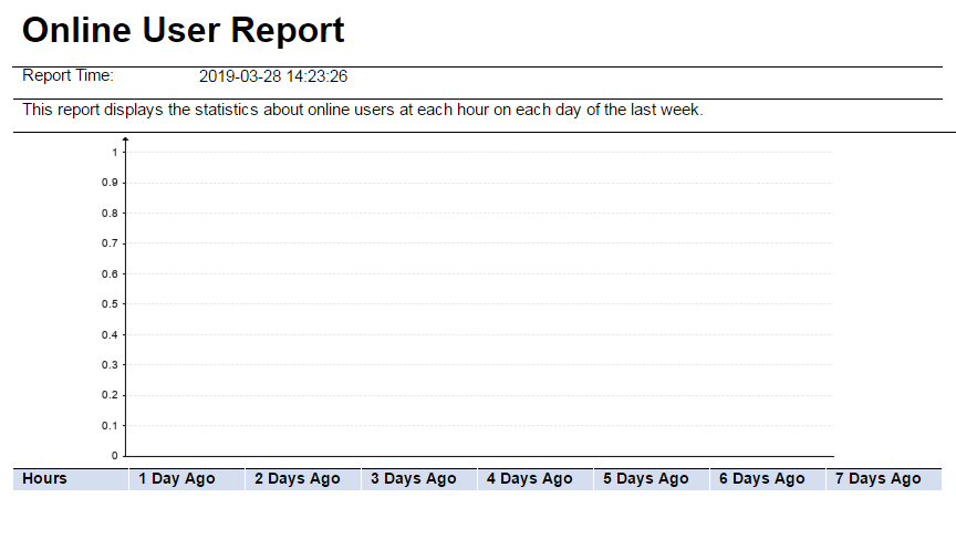
Per User Data Usage report
The Per User Data Usage report displays the top 50 users whose total traffic equals or exceeds the specified traffic value for the last 7 days.
To view Per User Data Usage report:
1. Click the Report tab.
2. From the navigation tree, select Report Template List.
3. In the Query Templates area, select Access Service Report from the Type list, and then click Query.
All access service reports display in the Report Template List.
4. Click Per User Data Usage Report to open the parameter setting page.
5. Enter a lower limit for traffic counting in MB in the Total Bytes field.
The Per User Data Usage report contains the following fields:
· Total Bytes—Lower limit for traffic counting.
· Report Time—Time at which the report was generated.
· Description—Brief description of the report.
· User name—Name of the user.
· Total Bytes—Total traffic (in MB) of the user during the last 7 days, including upload and download traffic.
· Bytes In—Upload traffic (in MB) of the user during the last 7 days.
· Bytes Out—Download traffic (in MB) of the user during the last 7 days.
· Session Time (sec)—Total online time of the user during the last 7 days.
· Number of Logins—Total logins of the user during the last 7 days.
Service usage report
The Service Usage Report collects statistics about the services in use, number of users for each service, and the service being used by the current online user.
To view the Service Usage Report:
1. Click the Report tab.
2. From the navigation tree, select Report Template List.
3. In the Query Templates area, select Access Service Report from the Type list, and click Query. All access service reports display in the Report Template List.
4. Click Service Usage Report to open a real-time service usage report.
The Service Usage Report contains the following fields:
· Report Time—Time at which the report was generated.
· Description—Brief description of the report.
· Service—Service name in UAM.
· Number of Users—Total number of users who are assigned the service.
· Number of Online Users—Number of online users who are using the service.
Services that no users have applied for do not display in the Service Usage Report.
Test mode authentication failure log report
The Test Mode Authentication Failure Log Report classifies the authentication failure reasons and collects statistics on the number of accounts that failed the authentication due to each type of failure reason. This type of report is available only when the system parameter AuthN Test Mode is set to Enable.
To view the Test Mode Authentication Failure Log Report:
1. Click the Report tab.
2. From the navigation tree, select Report Template List.
3. In the Query Templates area, select Access Service Report from the Type list, and then click Query.
All access service reports display in the Report Template List.
4. Click Test Mode Authentication Failure Log Report.
5. Select the start date from the Start Time list.
6. Select the end date from the End Time list.
7. Click OK to open the test mode authentication failure log report.
The Test Mode Authentication Failure Log Report contains the following fields:
· Start Time/End Time—The collection time range (inclusive) for the statistics. Statistics are not collected for the day that the report was generated. Even if you select the day that the report was generated or a later date, only statistics from the start time to the previous day are included.
· Report Time—Time at which the report was generated.
· Description—Brief description of the report.
· Authentication Failure Cause—Authentication failure reason.
· Number of Failure—Number of authentication failures. The statistics help operators to identify the major problems in the authentication network.
Managing scheduled reports
For scheduled reports, the operator predefines the generation period and report template. The operator can view reports generated at different times. UAM also supports sending reports to the operator by email.
Authentication failure category statistics report
An authentication failure category statistics report collects statistics about reasons for authentication failure in a specified time range and number of users for each failure reason.
Adding an authentication failure category statistics report
1. Use one of the following methods to display the page for adding a scheduled report:
¡ Click the Report tab and select Reports > Add Scheduled Report from the navigation tree.
¡ Click the Report tab, select Scheduled Reports > All Scheduled Reports from the navigation tree, and click Add.
2. Select a template for the authentication failure category statistics report:
a. Click Select to the right of Template Name.
b. In the Query Templates area, select Access Service Report from the Type list and click Query.
c. Select Auth Failure Category Statistic Report.
d. Click OK.
3. Input the report name in the Scheduled Report Name field.
4. Select operator groups that can view the report:
a. Click the Operator
Group Information icon ![]() to the right of the Access Right field.
to the right of the Access Right field.
The Operator Group Information window opens.
b. On the Operator Group List area, select one or more operator groups.
All operators contained in the selected operator groups appear on the right.
c. Click Close.
5. Specify the frequency at which the report is generated.
A scheduled report period is determined by both the schedule type and schedule time settings.
¡ Schedule Type—Contains fields such as Daily, Weekly, Monthly, Quarterly, Half Yearly, and Yearly.
¡ Report Start Date—Enter a report
start time in the format of YYYY-MM-DD, or click the Calendar icon ![]() to select a start
date.
to select a start
date.
If you select the Daily schedule type, reports of the previous day are generated every day. For example, if you set the report start date to 2011-08-10, the first daily report is generated at 04:00 a.m. on 2011-08-11, and the data on 2011-08-11 displays in the report.
If you select the Weekly schedule type, reports of the previous 7 days are generated every seven days. For example, if you set the report start time to 2011-08-10, the first weekly report is generated at 04:00 a.m. on 2011-08-17, and the data from 2011-08-10 to 2011-08-16 displays in the report.
If you select the Monthly schedule type, reports of the previous month are generated every month. For example, if you set the report start time to 2011-08-10, the first monthly report is generated at 04:00 a.m. on 2011-09-10, and the data from 2011-08-10 to 2011-09-09 displays in the report.
If you select the Quarterly schedule type, reports of the previous 3 months are generated every 3 months. For example, if you set the report start time to 2011-08-10, the first quarterly report is generated at 04:00 a.m. on 2011-11-10, and the data from 2011-08-10 to 2011-11-09 displays in the report.
If you select the Half Yearly schedule type, reports of the last half year are generated every half year. For example, if you set the report start time to 2011-08-10, the first half yearly report is generated at 04:00 a.m. on 2011-02-10, and the data from 2011-08-10 to 2011-02-09 displays in the report.
If you select the Yearly schedule type, reports of the previous year are generated every year. For example, if you set the report start time to 2011-08-10, the first yearly report is generated at 04:00 a.m. on 2011-08-10, and the data from 2011-08-10 to 2012-08-09 displays in the report.
6. To disable UAM from generating scheduled reports, set the time at which a report becomes invalid by using one of the following methods:
¡ Select the End by option and enter a time string in the format of YYYY-MM-DD hh:mm.
¡ Click the Calendar icon ![]() to select the end date, and then enter the end time at the lower part.
to select the end date, and then enter the end time at the lower part.
7. Select a file format from the Report File Format list. These options are available: PDF, CSV, MS Excel, and MS Excel (Data-only).
8. To send a report by email, select the Send by Email option and enter the email address of the receiver. Reports can be sent to only one email address.
9. Set the begin time and end time to collect statistics:
a. Click the Set Parameter
icon ![]() for the begin time.
for the begin time.
b. Select an option from the Schedule Parameter list. The options vary depending on the schedule type configured in step 5.
For the Daily schedule type, the options include Begin time, One hour after begin time through Twenty-three hours after begin time, and End time.
For the Weekly schedule type, the options include Begin time, One day after begin time through Six days after begin time, and End time.
For the Monthly schedule type, the options include Begin time, One day after begin time through Thirty days after begin time, and End time.
For the Quarterly schedule type, the options include Begin time, One month after begin time, Two months after begin time, and End time.
For the Half Yearly schedule type, the options include Begin time, One month after begin time, Five months after begin time, and End time.
For the Yearly schedule type, the options include Begin time, One month after begin time, Eleven months after begin time, and End time.
c. Click OK to return to the page for adding a
report. The parameter setting link changes from the Set Parameter icon ![]() to the Successful Corresponding Operation icon
to the Successful Corresponding Operation icon ![]() .
.
d. Set the end time in the same way the begin time is set.
For example, a report is the Daily schedule type and the start date is set to 2011-08-10. Set the begin time and end time to 2 hours and 10 hours after the start date begins, respectively. UAM generates the daily report at 00:00 every day, which contains data only from 2:00 to 10:00 on the previous day.
10. Click OK.
Viewing authentication failure category statistics reports that have been generated
1. Click the Report tab.
2. From the navigation tree, select Reports > All Scheduled Reports.
3. Click the History
Report icon ![]() for the target service.
for the target service.
4. Click the View link to open a statistics report, or save the statistics report.
The authentication failure category statistics report contains the following fields and chart:
· Start Time/End Time—Statistics collection time range (inclusive).
· Report Time—Time at which the report was generated.
· Description—Brief description of the report.
· Pie chart—Displays the number of users, ratio, and total number of users who have failed the authentication. Reported types of authentication failures can include identity authentication error, blacklist, binding check failure, LDAP error, and others.
In the report, the following guidelines apply:
· If an account is cancelled, authentication failure statistics about the account are not collected.
· If a user goes offline after the user passes authentication for a service, when the user cancels applying for the service, the authentication failure statistics for using the service are not collected.
· Authentication failure statistics caused by using incorrect service suffixes are counted as identity authentication errors.
Idle account report
An idle account refers to an account that has not gone online for a specified period of time..
An idle account report collects statistics about accounts with an idle period greater than the specified idle period.
Adding an idle account report
1. Use one of the following methods to display the page for adding a scheduled report:
¡ Click the Report tab and select Reports > Add Scheduled Report from the navigation tree.
¡ Click the Report tab, select Scheduled Reports > All Scheduled Reports from the navigation tree, and click Add.
2. Select a template for the idle account report:
a. Click Select to the right of Template Name.
b. In the Query Templates area, select Access Service Report from the Type list and click Query.
c. Select Idle Account Report.
d. Click OK.
3. Enter the report name in the Scheduled Report Name field.
4. Select operator groups that can view the report:
a. Click the Operator
Group Information icon ![]() to the right of the Access Right field.
to the right of the Access Right field.
The Operator Group Information window opens.
b. On the Operator Group List area, select one or more operator groups.
All operators contained in the selected operator groups appear on the right.
c. Click Close.
5. Specify the frequency at which the report is generated.
A scheduled report period is determined by both the schedule type and schedule time settings.
¡ Schedule Type—Contains fields such as Daily, Weekly, Monthly, Quarterly, Half Yearly, and Yearly.
¡ Creation Date From/To—Enter the report
start time in the format of YYYY-MM-DD, or click the Calendar icon ![]() to select the report
start time.
to select the report
start time.
If you select the Daily schedule type, reports of the previous day are generated every day. For example, if you set the report start time to 2011-08-10, the first daily report is generated at 04:00 a.m. on 2011-08-11, and the data at 00:00 on the day when the report was generated displays in the report.
If you select the Weekly schedule type, reports of the previous 7 days are generated every seven days. For example, if you set the report start time to 2011-08-10, the first weekly report is generated at 04:00 a.m. on 2011-08-17, and the data at 00:00 on the day when the report was generated displays in the report.
If you select the Monthly schedule type, reports of the previous month are generated every month. For example, if you set the report start time to 2011-08-10, the first monthly report is generated at 04:00 a.m. on 2011-09-10, and the data at 00:00 on the day when the report was generated displays in the report.
If you select the Quarterly schedule type, reports of the previous 3 months are generated every 3 months. For example, if you set the report start time to 2011-08-10, the first quarterly report is generated at 04:00 a.m. on 2011-11-10, and the data at 00:00 on the day when the report was generated displays in the report.
If you select the Half Yearly schedule type, reports of the last half year are generated every half year. For example, if you set the report start time to 2011-08-10, the first half yearly report is generated at 04:00 a.m. on 2012-02-10, and the data at 00:00 on the day when the report was generated displays in the report.
If you select the Yearly schedule type, reports of the previous year are generated every year. For example, if you set the report start time to 2011-08-10, the first yearly report is generated at 04:00 a.m. on 2012-08-10, and the data at 00:00 on the day when the report was generated displays in the report.
6. To disable UAM from generating scheduled reports, set the time at which a report becomes invalid by using one of the following methods:
¡ Select the End by option and enter a time string in the format of YYYY-MM-DD hh:mm.
¡ Click
the Calendar icon ![]() to select an end date, and then enter the end time at the lower part.
to select an end date, and then enter the end time at the lower part.
7. Select a file format from the Report File Format list. These options are available: PDF, CSV, MS Excel, and MS Excel (Data-only).
8. To send a report by email, select the Send by Email option and enter the email address of the receiver. Reports can be sent to only one email address.
9. Set an idle period:
a. Click the Set Parameter
icon ![]() for Idle Period
to display the page for setting
parameters.
for Idle Period
to display the page for setting
parameters.
b. Enter an idle period in the Parameter Value field. Only accounts with an idle period greater than the configured idle period display in the report.
c. Click OK.
d. Click OK to
return to the page for adding a report. The parameter setting link changes from
the Set Parameter icon ![]() to the Successful Corresponding Operation
icon
to the Successful Corresponding Operation
icon ![]() .
.
10. Select a user group:
a. Click the Set Parameter
icon ![]() for User Group
to display the Set Parameter page.
for User Group
to display the Set Parameter page.
b. Select a user group from the Parameter Value list. Only accounts in the selected user group display in the report.
c. Click OK to
return to the page for adding a report. The parameter setting link changes from
the Set Parameter icon ![]() to the Successful Corresponding Operation
icon
to the Successful Corresponding Operation
icon ![]() .
.
11. Click OK.
Viewing idle account reports that have been generated
1. Click the Report tab.
2. From the navigation tree, select All Scheduled Reports.
3. Click the History
Report icon ![]() of the target service
report to display the History Report page.
of the target service
report to display the History Report page.
4. Click the View link to open a statistics report, or save the statistics report.
The idle account report contains the following fields:
· Idle Period—Idle period for the account. Only accounts whose idle period is greater than the value display in the report.
· User Group—User group to which the accounts displayed in the report belongs.
· Report Time—Time at which the report is generated. Data in the report is the data generated at this time.
· Description—Brief description of the report.
· User Name—User name corresponding to the accounts.
· User Group—User group to which the accounts belong.
· Account Name—Account name used by a user when the user is authenticated.
· Last-offline—Time at which an account goes offline the last time. This field is empty if the account never accesses the network when the account is created.
· Create at—Time at which an account was created. If the account never accesses the network when the account is created, the last-offline time of the account is the time at which the account was created.
· Idle Period—Period during which an account is idle. The accounts display according to the idle period in descending order.
· Total—Total number of idle accounts in the table. If the report has multiple pages, this field displays on the last page.
Offline reason report
An offline reason report collects statistics about offline reasons in a specified time range and number of users for each offline reason. For an example of an offline reason report, see Figure 151.
Adding an offline reason report
1. Use one of the following methods to display the page for adding a scheduled report:
¡ Click the Report tab and select Reports > Add Scheduled Report from the navigation tree.
¡ Click the Report tab, select Scheduled Reports > All Scheduled Reports from the navigation tree, and click Add.
2. Select a template for the offline reason report:
a. Click Select to the right of Template Name.
b. In the Query Templates area, select Access Service Report from the Type list and click Query.
c. Select Offline Reason Report.
d. Click OK.
3. Input the report name in the Scheduled Report Name field.
4. Select operator groups that can view the report:
a. Click the Operator
Group Information icon ![]() to the right of the Access Right field.
to the right of the Access Right field.
The Operator Group Information window opens.
b. On the Operator Group List area, select one or more operator groups.
All operators contained in the selected operator groups appear on the right.
c. Click Close.
5. Specify the frequency at which the report is generated.
A scheduled report period is determined by both the schedule type and schedule time settings.
¡ Schedule Type—Contains fields such as Daily, Weekly, Monthly, Quarterly, Half Yearly, and Yearly.
¡ Creation Date From/To—Enter the
report start time in the format of YYYY-MM-DD, or click the Calendar icon ![]() to select the
report start time.
to select the
report start time.
If you select the Daily schedule type, reports of the previous day are generated every day. For example, if you set the report start time to 2011-08-10, the first daily report is generated at 04:00 a.m. on 2011-08-11, and the data in the report is the data collected until 00:00 on the day that the report was generated.
If you select the Weekly schedule type, reports of the previous 7 days are generated every seven days. For example, if you set the report start time to 2011-08-10, the first weekly report is generated at 04:00 a.m. on 2011-08-17, and the data from 2011-08-10 to 2011-08-16 displays in the report.
If you select the Monthly schedule type, reports of the previous month are generated every month. For example, if you set the report start time to 2011-08-10, the first monthly report is generated at 04:00 a.m. on 2011-09-10, and the data from 2011-08-10 to 2011-09-09 displays in the report.
If you select the Quarterly schedule type, reports of the previous 3 months are generated every 3 months. For example, if you set the report start time to 2011-08-10, the first quarterly report is generated at 04:00 a.m. on 2011-11-10, and the data from 2011-08-10 to 2011-11-09 displays in the report.
If you select the Half Yearly schedule type, reports of the last half year are generated every half year. For example, if you set the report start time to 2011-08-10, the first half yearly report is generated at 04:00 a.m. on 2012-02-10, and the data from 2011-08-10 to 2011-02-09 displays in the report.
If you select the Yearly schedule type, reports of the last are generated every year. For example, if you set the report start time to 2011-08-10, the first yearly report is generated at 04:00 a.m. on 2012-08-10, and the data from 2011-08-10 to 2012-08-09 displays in the report.
6. Set the time at which a report becomes invalid (optional). Then, UAM does not generate any scheduled report.
¡ Select the End by box, and enter an end date and time in the format of YYYY-MM-DD hh:mm.
¡ Click
the Calendar icon ![]() to select an end date and then enter an end time at the lower part.
to select an end date and then enter an end time at the lower part.
7. Select a file format from the Report File Format list. These options are available: PDF, CSV, MS Excel, and MS Excel (Data-only).
8. To send a report by email, select the Send by Email option and enter the email address of the receiver. Reports can be sent to only one email address.
9. Set the begin time and end time to collect statistics:
a. Click the Set Parameter
icon ![]() for the begin time.
for the begin time.
b. Select an option from the Parameter Value list. The options vary depending on the schedule type configured in step 5.
For the Daily schedule type, the options include Begin time, One hour after begin time through Twenty-three hours after begin time, and End time.
For the Weekly schedule type, the options include Begin time, One day after begin time through Six days after begin time, and End time.
For the Monthly schedule type, the options include Begin time, One day after begin time through Thirty days after begin time, and End time.
For the Quarterly schedule type, the options include Begin time, One month after begin time, Two months after begin time, and End time.
For the Half Yearly schedule type, the options include Begin time, One month after begin time, Five months after begin time, and End time.
For the Yearly schedule type, the options include Begin time, One month after begin time, Eleven months after begin time, and End time.
c. Click OK to
return to the page for adding a report. The parameter setting link changes from
the Set Parameter icon ![]() to the Successful Corresponding Operation
icon
to the Successful Corresponding Operation
icon![]() .
.
d. Set the end time in the same way the begin time is set.
For example, a report is the Daily schedule type and the start date is set to 2011-08-10. Set the begin time and end time to 2 hours and 10 hours after the start date begins, respectively. UAM generates the daily report at 00:00 every day, which contains data only from 2:00 to 10:00 on the previous day.
10. Click OK.
Viewing offline reason reports that have been generated
1. Click the Report tab.
2. From the navigation tree, select Scheduled Reports > All Scheduled Reports.
3. Click the History
Report icon ![]() for the offline reason
report to display the History Report page.
for the offline reason
report to display the History Report page.
4. Click the View link to open a statistics report, or save the statistics report.
The offline reason report contains the following fields and chart:
· Start Time/End Time—Statistics collection time range (inclusive).
· Report Time—Time at which the report was generated.
· Description—Brief description of the report.
· Pie chart—Displays statistics about offline reasons in a specified time range and number of users for each offline reason. The offline failure reasons include:
¡ User Request—The user requests to go offline.
¡ Lost Carrier—Heartbeat packets between the authenticated client and device are lost when 802.1X authentication is used.
¡ Lost Service—The access device cannot provide access services for the user. For example, the physical connection between the user and device is broken.
¡ Idle Timeout—The user timed out.
¡ Session Timeout—The session timed out.
¡ Admin Reset—The administrator resets the port or session.
¡ Admin Reboot—The administrator terminates the access service. For example, the device reboots as the administrator configured.
¡ Port Error—The access device detects an access port failure and stops all sessions on the port.
¡ NAS Error—The access device fails and all sessions on the device are closed.
¡ NAS Request—Events cause the access device to stop the session.
¡ NAS Reboot—An unscheduled device reboot has occurred. For example, device reboot after power down or crash.
¡ Port Unneeded—The device port is unavailable. For example, assume a user is connected to an on-demand dialup port. Because no traffic is generated for a certain period of time, the device shuts down the port according to the on-demand dialup algorithm.
¡ Port Preempted—The access device terminates all sessions on the port to increase port priority.
¡ Port Suspended—The access device terminates all sessions on the port to create a virtual session.
¡ Service Unavailable—The access device does not support the service requested by the user.
¡ Callback—The access device terminates the session with the user to execute Callback for another session.
¡ User Error—The access device terminates the session with the user because incorrect session information is sent by the user.
¡ Host Request—The user endpoint requests to go offline.
¡ Enabling Proxy—A proxy server is used when the proxy server is prohibited in UAM.
¡ Enabling Double NICs—The user enables multiple NICs when multi-NIC is prohibited in UAM.
¡ Setting Proxy in Browser—Proxy is enabled in the browser when browser proxy is prohibited in UAM.
¡ Invalid Client Version—Invalid client version.
¡ Unknown Error—An unknown error has occurred.
¡ Online Check—UAM logs off the user because it does not receive any accounting update packets within the configured aging time.
¡ Online Delete—An operator performs the Online Delete operation for the user in UAM.
In the report, the following guidelines apply:
· Offline reason and offline counts are not collected for logged-off users in UAM.
· If a user goes offline after the user passes authentication for a service, when the user cancels applying for the service, the offline reason and count are not collected.
Online user report
This report collects online users per hour in the last seven days. For an example of an online user report, see Figure 152.
Adding an online user report
1. Use one of the following methods to display the page for adding a scheduled report:
¡ Click the Report tab and select Reports > Add Scheduled Report from the navigation tree.
¡ Click the Report tab, select Scheduled Reports > All Scheduled Reports from the navigation tree, and click Add.
2. Select a template:
a. Click Select to the right of Template Name.
b. In the Query Templates area, select Access Service Report from the Type list and click Query.
c. Select Online User Report.
d. Click OK.
3. Input the report name in the Scheduled Report Name field.
4. Select operator groups that can view the report:
a. Click the Operator
Group Information icon ![]() to the right of the Access Right field.
to the right of the Access Right field.
The Operator Group Information window opens.
b. On the Operator Group List area, select one or more operator groups.
All operators contained in the selected operator groups appear on the right.
c. Click Close.
5. Specify the frequency at which the report is generated.
A scheduled report period is determined by both the schedule type and schedule time settings.
¡ Schedule Type—Contains fields such as Daily, Weekly, Monthly, Quarterly, Half Yearly, and Yearly.
¡ Creation Date From/To—Enter the report
start time in the format of YYYY-MM-DD, or click the Calendar icon ![]() to select the report
start time.
to select the report
start time.
If you select the Daily schedule type, reports of the previous day are generated every day. For example, if you set the report start time to 2011-08-10, the first daily report is generated at 04:00 a.m. on 2011-08-11. Online users per hour from 2011-08-10 to 2011-08-11 are displayed in the report.
If you select the Weekly schedule type, reports of the previous 7 days are generated every seven days. For example, if you set the report start time to 2011-08-10, the first weekly report is generated at 04:00 a.m. on 2011-08-17. Online users per hour from 2011-08-10 to 2011-08-16 are displayed in the report.
If you select the Monthly schedule type, reports of the previous month are generated every month. For example, if you set the report start time to 2011-08-10, the first monthly report is generated at 04:00 a.m. on 2011-09-10. Online users per hour form 2011-08-10 to 2011-09-09 are displayed in the report.
If you select the Quarterly schedule type, reports of the previous 3 months are generated every 3 months. For example, if you set the report start time to 2011-08-10, the first quarterly report is generated at 04:00 a.m. on 2011-11-10. Online users per hour from 2011-08-10 to 2011-11-09 are displayed in the report.
If you select the Half Yearly schedule type, reports of the last half year are generated every half year. For example, if you set the report start time to 2011-08-10, the first half yearly report is generated at 04:00 a.m. on 2012-02-10. Online users per hour from 2011-08-10 to 2012-02-09 are displayed in the report.
If you select the Yearly schedule type, reports of the last year are generated every year. For example, if you set the report start time to 2011-08-10, the first yearly report is generated at 04:00 a.m. on 2012-08-10. Online users per hour from 2011-08-10 to 2012-08-09 are displayed in the report.
6. To disable UAM from generating scheduled reports, set the time at which a report becomes invalid by using one of the following methods:
¡ Select the End by option and enter a time string in the format of YYYY-MM-DD hh:mm.
¡ Click
the Calendar icon ![]() to select the end date, and then enter the end time at the lower part.
to select the end date, and then enter the end time at the lower part.
7. Select a file format from the Report File Format list. These options are available: PDF, CSV, MS Excel, and MS Excel (Data-only).
8. To send a report by email, select the Send by Email option and enter the email address of the receiver. Reports can be sent to only one email address.
9. Click OK.
Viewing online user reports that have been generated
1. Click the Report tab.
2. From the navigation tree, select Scheduled Reports > All Scheduled Reports.
3. Click the History
Report icon ![]() of the target service
report to display the History Report page.
of the target service
report to display the History Report page.
4. Click the View link to open a statistics report, or save the statistics report.
The online user report contains the following fields:
· Report Time—Time at which the report was generated.
· Description—Brief description of the report.
· Line chart—Number of online users in the last 7 days are displayed, and each day displays in a different color.
· Table—Online users per hour in the last 7 days are listed.
Service usage report
A service usage report collects statistics about the services in use, number of users for each service, and the services that online users are using when a scheduled report is generated.
Adding a service usage report
1. Use one of the following methods to display the page for adding a scheduled report:
¡ Click the Report tab and select Add Scheduled Report from the navigation tree.
¡ Click the Report tab, select Scheduled Reports > All Scheduled Reports from the navigation tree, and click Add.
2. Select a template:
a. Click Select to the right of Template Name.
b. In the Query Templates area, select Access Service Report from the Type list and click Query.
c. Select Service Usage Report.
d. Click OK.
3. Input the report name in the Scheduled Report Name field.
4. Select operator groups that can view the report:
a. Click the Operator
Group Information icon ![]() to the right of the Access Right field.
to the right of the Access Right field.
The Operator Group Information window opens.
b. On the Operator Group List area, select one or more operator groups.
All operators contained in the selected operator groups appear on the right.
c. Click Close.
5. Specify the frequency at which the report is generated.
A scheduled report period is determined by both the schedule type and schedule time settings.
a. Schedule Type—Contains fields such as Daily, Weekly, Monthly, Quarterly, Half Yearly, and Yearly.
b. Report Start Date—Enter a report start time in the format of
YYYY-MM-DD, or click the Calendar icon ![]() to select a start date.
to select a start date.
If you select the Daily schedule type, reports of the previous day are generated every day. For example, if you set the report start time to 2011-08-10, the first daily report is generated at 04:00 a.m. on 2011-08-10, and the data collected until 00:00 on the day that the report was generated displays in the report.
If you select the Weekly schedule type, reports of the last 7 days are generated every seven days. For example, if you set the report start time to 2011-08-10, the first weekly report is generated at 04:00 a.m. on 2011-08-17, and the data collected until 00:00 on the day that the report was generated displays in the report.
If you select the Monthly schedule type, reports of the previous month are generated every month. For example, if you set the report start time to 2011-08-10, the first monthly report is generated at 04:00 a.m. on 2011-09-10, and the data collected until 00:00 on the day that the report was generated displays in the report.
If you select the Quarterly schedule type, reports of the previous 3 months are generated every 3 months. For example, if you set the report start time to 2011-08-10, the first quarterly report is generated at 04:00 a.m. on 2011-11-10, and the data collected until 00:00 on the day that the report was generated displays in the report.
If you select the Half Yearly schedule type, reports of the last half year are generated every half year. For example, if you set the report start time to 2011-08-10, the first half yearly report is generated at 04:00 a.m. on 2012-02-10, and the data collected until 00:00 on the day that the report was generated displays in the report.
If you select the Yearly schedule type, reports of the last year are generated every year. For example, if you set the report start time to 2011-08-10, the first yearly report is generated at 04:00 a.m. on 2012-08-10, and the data collected until 00:00 on the day that the report was generated displays in the report.
6. To disable UAM from generating scheduled reports, set the time at which a report becomes invalid by using one of the following methods:
¡ Select the End by option and enter a time string in the format of YYYY-MM-DD hh:mm.
¡ Click
the Calendar icon ![]() to select the end date, and then enter the end time at the lower part.
to select the end date, and then enter the end time at the lower part.
7. Select a file format from the Report File Format list. These options are available: PDF, CSV, MS Excel, and MS Excel (Data-only).
8. To send a report by email, select the Send by Email option and enter the email address of the receiver. Reports can be sent to only one email address.
9. Click OK.
Viewing service usage reports that have been generated
1. Click the Report tab.
2. From the navigation tree, select Scheduled Reports > All Scheduled Reports.
3. Click the History
Report icon ![]() of the target service
report to display the History Report page.
of the target service
report to display the History Report page.
4. Click the View link to open a service usage report, or save the service usage report.
Service usage report fields:
· Report Time—Time at which the report is generated.
· Description—Brief description of the report.
· Service—Service name in UAM.
· Number of Users—Total number of users who are assigned the service.
· Number of Online Users—Number of online users who are using the service.
Services that no users apply for do not display in the service usage report.
Managing UAM widgets
UAM provides predefined widgets that use tables and graphics to display realtime user and service statistics.
UAM widgets support basic operations, such as adding, configuring, modifying, and deleting widgets. The operation procedures are the same as the procedures for IMC platform widgets. For more information about the basic widget operations, see HPE Intelligent Management Center v7.3 Enterprise and Standard Platform Administrator Guide.
The following information describes fields and parameters of each UAM widget.
Top 5 access devices by online count
This widget displays the top 5 access devices that have the most online users in UAM.
Figure 137 Top 5 access devices by online count
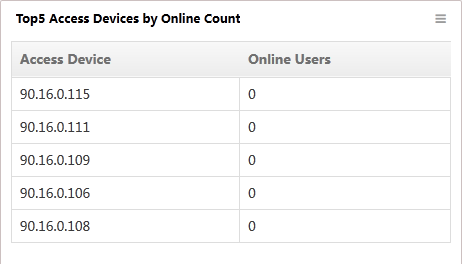
Widget parameters
· Access Device—IP address of the access device.
· Online Users—Number of users that come online from the access device.
Endpoint device statistics
This widget displays endpoint types in UAM and the number of endpoint devices for each type. Endpoints are categorized as Unknown if UAM cannot obtain their types.
To view the percentage of endpoint devices for an endpoint type, point to the endpoint type.
Figure 138 Endpoint device statistics
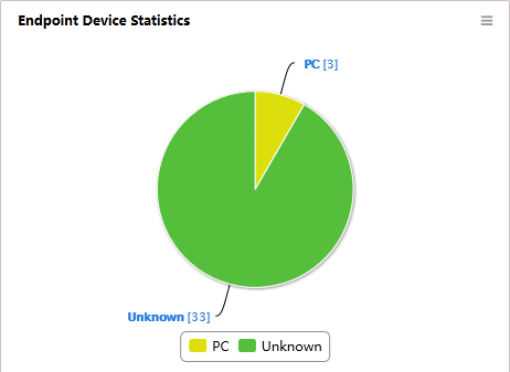
24-hour online history
This widget displays online user statistics in last 24 hours. The horizontal axis represents the time and the vertical axis represents the number of online users. When the EAD Security Policy component is deployed, the widget also displays the online user numbers by security check status.
Figure 139 24-hour online history
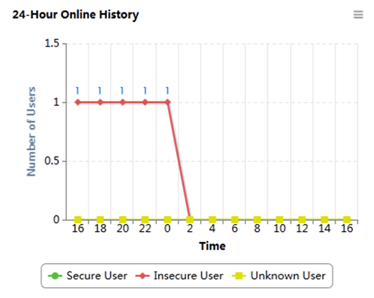
Widget parameters
The following parameters are displayed when EAD Security Policy is deployed:
· Secure User—Number of online users who have passed the security check.
· Insecure User—Number of online user who have failed the security check.
· Unknown User—Number of online users who are waiting for the security check or who are not required a security check.
User groups by online count
This widget displays the top 10 user groups that have the most online users. User groups that do not have an online user are not displayed in the widget.
Figure 140 User groups by online count
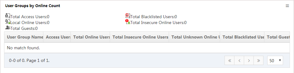
Widget parameters
· Total Access Users—Total number of access users in UAM.
· Total Blacklisted Users—Total number of blacklisted users in UAM.
· Local Online Users—Total number of local online users in UAM.
· Total Insecure Online Users—Total number of insecure online users in UAM. This parameter is displayed only when EAD Security Policy is deployed.
· Total Guests—Total number of guests.
User group list content
· User Group Name—Name of the user group.
· Access Users—Number of access users in the user group.
· Total Online Users—Number of online users in the user group.
· Total Insecure Online Users—Number of insecure online users in the user group. This parameter is displayed only when EAD Security Policy is deployed.
· Total Unknown Online Users—Number of unknown online users in the user group.
· Total Blacklisted Users—Number of blacklisted users in the user group.
· Total Guests—Number of guests in the user group.
EIA license
This widget displays a gauge and statistics for the EIA license usage.
Figure 141 EIA license
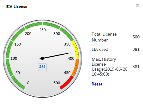
Widget parameters
· Total License Number—Maximum number of online users permitted by the EIA license.
· EIA used—Number of current online users in EIA.
· Max. History License Usage—Peak number of online users in history records. When the number reaches or exceeds 95% of the total number permitted by the license, a critical alarm is triggered. After the alarm is recovered, you can click Reset for the counter of this field.
Top 5 services by user count
This widget displays the top 5 access services that have been assigned to users and the user statistics.
Figure 142 Top 5 services by user count
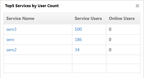
Widget parameters
· Service Name—Name of the access service.
· Service Users—Number of users that have been assigned the access service.
· Online Users—Number of online users that came online by using the access service.
Online users client usage
This widget displays iNode client versions that are used by online users and the number of online users for each version.
Figure 143 Online users client usage
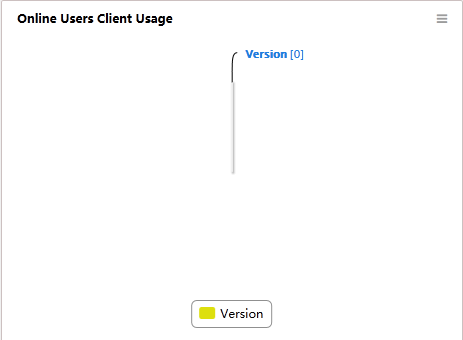
Blacklist user statistics
This widget displays blacklist user statistics.
Figure 144 Blacklist user statistics
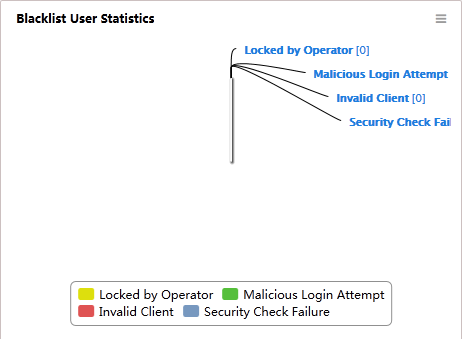
Widget parameters
· Locked by Operator—Users that were considered insecure and manually disabled by the operator from accessing the network.
· Malicious Login Attempt—Users that were automatically disabled by the system when the number of user authentication failures had reached the value of the system parameter Max. Authentication Attempts.
· Invalid Client—Users that were automatically disabled when they came online by using an invalid client. A client is considered invalid if it does not meet the lowest version required by UAM, or if its version is not uploaded to UAM. This function is controlled by the Add Invalid Client to Blacklist parameter in UAM system parameter configuration.
· Security Check Fail—Users that were automatically disabled because they had failed the security check. This parameter is displayed only when EAD Security Policy is deployed.
Configuring device management users
Device management users, also called device administrators or device operators, are users who can log in to and manage network devices.
An authentication process occurs when a device management user attempts to log in to a device. Typically the device performs authentication with the locally stored user name and password. With UAM deployed to the network, the authentication process does not necessarily occur on the device. Instead, UAM can use the RADIUS service to authenticate the device management user. Operators can manage device management users in UAM to reduce management cost and enhance network security.
UAM can authenticate device management users of the following login methods:
· Telnet
· SSH
· FTP
· Terminal
To authenticate device management users in UAM, complete the following configurations:
1. Add device management users to UAM and configure the users.
2. Configure the related devices as access devices in UAM.
3. Configure AAA authentication on the devices.
You can audit the login behaviors of the device management users by using the UAM authentication logs of device management users.
Configuring device user groups in UAM
In UAM, you can view, add, modify, and delete device user groups. When you add a user group, configure the login type and EXEC priority for the group. By default, a user group applies the login type and EXEC priority settings to all members of the group. If a group member is configured with different settings, the member settings apply.
Accessing the device user group list page
1. Click the User tab.
2. From the navigation tree, select Access User > Device User > Device User Group.
The list includes all device user groups.
Device user group list contents
¡ Group Name—Name of the device user group.
¡ Login Type—Login type of the device user group. Options include Telnet, FTP, SSH, and Terminal.
¡ EXEC Priority—Level of the command execution privilege assigned to the device user group. The value is an integer in the range of 0 to 15. The supported value range varies by device model. A greater value represents a higher privilege, which grants users to execute more commands. If the parameter is not configured, this field displays two consecutive hyphens (--), and the device user group use the default level specified on the device.
¡ Modify—Click the Modify icon ![]() to modify the device user group.
to modify the device user group.
¡ Delete—Click the Delete icon ![]() to delete the device user group.
to delete the device user group.
Adding a device user group
1. Access the device user group list page.
2. Click Add.
The Add Device User Group page opens.
3. Configure the following parameters:
¡ Group Name—Enter the name of the device user group.
¡ Login Type—Select a login type for the device user group. Options are Telnet, FTP, SSH, and Terminal.
¡ FTP Directory—Enter the accessible FTP directory for the device user group. This field is displayed only when the Login Type is FTP. If the parameter is not configured, the group member enters the default FTP directory on the device. If you configure a nonexistent directory, the group member might fail to log into the device.
¡ EXEC Priority—Enter the level of the command execution privilege assigned to the device user group. The value is an integer in the range of 0 to 15. A greater value represents a higher privilege, which grants users to execute more commands. If the parameter is not configured, the group member uses the default level specified on the device.
4. Click OK.
Modifying a device user group
1. Access the device user group list page.
2. Click the Modify
icon ![]() for the device user group you want to modify.
for the device user group you want to modify.
The page for modifying the device user group opens.
3. Modify information about the device user group except the group name. For more information, see "Adding a device user group."
4. Click OK.
Deleting a device user group
You cannot delete a device user group that contains device management users.
To delete a device user group:
1. Access the device user group list page.
2. Click the Delete
icon ![]() for a device user group.
for a device user group.
A confirmation dialog box opens.
3. Click OK.
Configuring device management users in UAM
UAM allows you to manage device management users in the Access User module.
Accessing the device management user list page
1. Click the User tab.
2. From the navigation tree, select Access User > Device User > Device User.
The list includes all device users.
Device management user list contents
¡ Account Name—Login name of the device management user. Click the name of a device management user to view its details. For more information, see "Viewing device management user details."
¡ Full Name—Full name of the device management user.
¡ Login Type—Login type of a device management user. Options include Telnet, SSH, FTP, and Terminal.
¡ EXEC Priority—Level of the command execution privilege assigned to the device management user. The value is an integer in the range of 0 to 15, and varies with device models. A greater value represents a higher privilege, which grants users to execute more commands. If the parameter is not configured, this field displays two consecutive hyphens (--), and the device management user uses the default level specified on the device.
¡ Created on—Date when the device management user was created, in the format of YYYY-MM-DD.
¡ LDAP Policy—Name of the LDAP synchronization policy bound to the device management user. The field is empty if the device management user is not bound to any LDAP synchronization policy. Click the name of the LDAP synchronization policy to view detailed information about the policy. For more information, see "Managing LDAP synchronization policies."
¡ Last Synchronization—Execution result of the last LDAP synchronization, Success or Failure. The field is empty if the device management user is not bound to any LDAP synchronization policy.
¡ Modify—Click the Modify icon ![]() to modify the device management user.
to modify the device management user.
Querying device management users
1. Access the device user list page.
2. Specify one or more of the following query criteria:
¡ Account Name—Enter a partial or complete login name of a device management user. For example, if you enter bob, all account names that contain bob are matched.
¡ Login Type—Select a login type from the list. Options include Telnet, SSH, FTP, and Terminal.
The query ignores empty fields.
3. Click Query.
The list includes all device users matching the query criteria.
4. To clear the query criteria, click Reset.
The list includes all device management users.
Viewing device management user details
1. Access the device user list page.
2. Click the name of an account to view its details.
The user details page includes the following areas and parameters:
Basic information area parameters:
¡ Account Name—Login name of the device management user.
¡ Full Name—Full name of the device management user.
¡ Login Type—Login type of the device management user. Options include Telnet, SSH, FTP, and Terminal.
¡ Service Type—Value of the service type in the Access-Accept packet sent to the device after the device management user passes authentication. If this field is not configured, UAM sends the default value of the service type in the Access-Accept packet to the device. The value of the service type includes:
- Login—The user should be connected to a host.
- Framed—A Framed Protocol should be enabled for the user, such as PPP or SLIP.
- Callback Login—The user should be disconnected and called back, and then be reconnected to a host.
- Callback Framed—The user should be disconnected and called back, and then a Framed Protocol should be enabled for the User, such as PPP or SLIP.
- Outbound—The user should be granted access to outgoing devices.
- Administrative—The user should be granted access to the NAS through the administrative interface from which privileged commands can be executed.
- NAS Prompt—The user should be provided a command prompt on the NAS from which non-privileged commands can be executed.
- Authenticate Only—Only Authentication is requested, and no authorization information is returned in the Access-Accept packet (typically used by proxy servers rather than the NAS).
- Callback NAS Prompt—The user should be disconnected and called back, and then be provided with a command prompt on the NAS from which non-privileged commands can be executed.
- Call Check—Used by the NAS in an Access-Request packet to indicate that a call is being received and that the RADIUS server should send back an Access-Accept packet to answer the call, or in an Access-Reject packet to not accept the call, typically based on the Called-Station-Id or Calling-Station-Id attributes. As a best practice, use the value of Calling-Station-Id in the Access-Request packets as the value of the User-Name.
- Callback Administrative—The user should be disconnected and called back, and then be granted access to the NAS through the administrative interface from which privileged commands can be executed.
¡ EXEC Priority—Level of the command execution privilege assigned to the device management user. The value is an integer in the range of 0 to 15, and varies with device models. A greater value represents a higher privilege, which grants users to execute more commands. If the parameter is not configured, this field displays two consecutive hyphens (--), and the user uses the default level specified on the device.
¡ FTP Directory—Accessible FTP directory for the device management user. This field is displayed only when the Login Type is FTP. If the parameter is not configured, this field displays two consecutive hyphens (--), and the user enters the default FTP directory on the device.
¡ Role Name—Role assigned to the device management user. This feature is supported on HP Comware and partial H3C devices.
¡ Bound user IP list contents area displays the IPv4 or IPv6 addresses that are bound to the device management users. UAM allows the device management user to log in to a device only when the IP address of the user is on the list.
This area does not appear for the Terminal login type.
¡ Start IP/End IP—Range of IP addresses permitted for logins. UAM supports multiple IP address ranges in this field, and the device management user to log in to a device if the IP address of the user belongs to one of the listed IP address ranges.
¡ IP address list of managed devices area displays IPv4 or IPv6 addresses of the devices managed by the device management user. UAM allows the device management user to log in to only the listed devices.
¡ Start IP/End IP—IPv4 address range for the managed devices.
3. Click Back to return to the device management user list page.
Adding a device management user
1. Access the device user list page.
2. Click Add.
The Add Device User page opens.
3. Configure basic information about the device management user:
¡ Account Name—Enter the login name of the device management user. The account name must be unique in the device management users, but can be the same as an access user account.
¡ Full Name—Enter the full name of the device management user. A full name can be associated with multiple device management user accounts.
¡ User Password—Enter a login password for the device management user.
¡ Confirm Password—Enter the password again.
¡ Device User Group—Select a group for the device user.
¡ Login Type—Select a login type for the device management user from the list. Options include Telnet, SSH, FTP, and Terminal.
¡ Service Type—Select a service type sent to the device. UAM sets the value of the service type in the Access-Accept packet sent to the device after the device management user passes authentication. If this field is not configured, UAM sends the default value of the service type in the Access-Accept packet to the device. The value of the service type includes:
- Login—The user should be connected to a host.
- Framed—A Framed Protocol should be enabled for the user, such as PPP or SLIP.
- Callback Login—The user should be disconnected and called back, and then be reconnected to a host.
- Callback Framed—The user should be disconnected and called back, and then a Framed Protocol should be enabled for the User, such as PPP or SLIP.
- Outbound—The user should be granted access to outgoing devices.
- Administrative—The user should be granted access to the NAS through the administrative interface from which privileged commands can be executed.
- NAS Prompt—The user should be provided a command prompt on the NAS from which non-privileged commands can be executed.
- Authenticate Only—Only Authentication is requested, and no authorization information is returned in the Access-Accept packet (typically used by proxy servers rather than the NAS).
- Callback NAS Prompt—The user should be disconnected and called back, and then be provided with a command prompt on the NAS from which non-privileged commands can be executed.
- Call Check—Used by the NAS in an Access-Request packet to indicate that a call is being received and that the RADIUS server should send back an Access-Accept packet to answer the call, or in an Access-Reject packet to not accept the call, typically based on the Called-Station-Id or Calling-Station-Id attributes. As a best practice, use the value of Calling-Station-Id in the Access-Request packets as the value of the User-Name.
- Callback Administrative—The user should be disconnected and called back, and then be granted access to the NAS through the administrative interface from which privileged commands can be executed.
¡ EXEC Priority—Enter the level of the command execution privilege assigned to the device management user. A greater value represents a higher privilege, which grants users to execute more commands. If the parameter is not configured, the user uses the default level specified on the device.
¡ Role Name—Enter a list of roles to be assigned to the device management user. This parameter is supported only on HP Comware and partial H3C devices.
¡ FTP Directory—Enter the accessible FTP directory for the device management user. This field is displayed only when the Login Type is FTP. If the parameter is not configured, the user enters the default FTP directory on the device. If you configure a non-existent directory, the device management user might fail to log into the device.
4. In the Bound User IP List, add the IPv4 or IPv6 address ranges that are bound with the device management user. This field does not appear for the Terminal login type.
To add IPv4 address ranges:
a. Click Add. The page for adding an IPv4 address range opens.
b. Enter the start and end IPv4 addresses. The start IPv4 address cannot be higher than the end IPv4 address.
c. Click OK.
d. Repeat the previous steps to add more IPv4 address ranges.
To add IPv6 address ranges:
a. Click Add IPv6 Address. The page for adding an IPv6 address range opens.
b. Enter an IPv6 address in the Start IPv6 Address field. The parameter specifies the first IPv6 user.
c. Enter a value in the IPv6 Address Span field. The parameter specifies the total number of IPv6 users. UAM then adds the IPv6 users in ascending order of IPv6 addresses. The value range is from 1 to 999. When this field is not configured or is set to 1, it indicates that the start IPv6 address and end IPv6 address are same.
d. Click OK.
e. Repeat the previous steps to add more IPv6 address ranges.
To delete an IP address range, click the Delete icon ![]() of the IP address range, and click OK in the dialog box that opens.
of the IP address range, and click OK in the dialog box that opens.
To clear the list, click Delete all.
5. In the IP Address List of Managed Devices area, configure the IP address list for devices managed by the user.
To add IPv4 address ranges:
a. Click Add. The page for adding an IPv4 address range opens.
b. Enter the start and end IPv4 addresses. The start IPv4 address cannot be higher than the end IPv4 address.
c. Click OK.
d. Repeat the previous steps to add more IPv4 address ranges.
To add IPv6 address ranges:
a. Click Add IPv6 Address. The page for adding an IPv6 address range opens.
b. Enter an IPv6 address in the Start IPv6 Address field. The parameter specifies the first IPv6 device to be added to UAM.
c. Enter a value in the IPv6 Address Span field. The parameter specifies the total number of IPv6 devices to be added to UAM. UAM then adds the IPv6 devices in ascending order of IPv6 addresses. The value range is from 1 to 999. When this field is not configured or is set to 1, it indicates that the start IPv6 address and end IPv6 address are same.
d. Click OK.
e. Repeat the previous steps to add more IPv6 address ranges.
To add access devices to the list:
a. Click Select Access Device. The page for selecting access devices opens.
b. In the access device list, select one or more devices.
c. Click OK.
To delete an IP address range or access device, click the Delete icon ![]() for the IP address range or access device, and click OK in the dialog box that opens.
for the IP address range or access device, and click OK in the dialog box that opens.
To clear the list, click Delete all.
6. Click OK.
Importing device management users in batches
1. Access the device user list page.
2. Click Batch Import.
The Import Device Users wizard is displayed.
3. Click Browse to select a file that stores the device management user information.
UAM supports importing only text files in ANSI code.
4. Select a column separator. Options include Space, TAB, comma (,), colon (:), pound sign (#), and dollar sign ($).
5. Select a user type. Options include Local User, which indicates users locally stored in UAM, and LDAP User, which indicates LDAP users bound with an LDAP synchronization policy.
6. Click Next.
UAM parses the text file and displays the number of columns in the list next to the parameters that support importing values.
7. Configure the following basic information:
¡ Account Name—Login name of the device management user. This parameter must be read from the file. Select a column number in the file as the account name.
¡ Full Name—Full name of the device management user.
¡ User Password—Login password for the device management user. This parameter can be either read from the file or manually specified. You can select a column number in the file, or select Not Imported and enter a value for all imported device management users.
¡ Device Management User Group—User group to which the device management user is assigned. This parameter cannot be read from the file. Select a group name from the list for all imported access devices.
¡ Login Type—Login type of the device management user. This parameter cannot be read from the file. Select a type from the list for all imported access devices. Options include Telnet, SSH, FTP, and Terminal.
¡ Service Type—Service type in Access-Accept packets sent to the devices managed by the user. This parameter cannot be read from the file. Select a service type from the list for all imported access devices. Options are Login, Framed, Callback Login, Callback Framed, Outbound, Administrative, NAS Prompt, Authenticate Only, Callback NAS Prompt, Call Check, and Callback Administrative.
¡ FTP Directory—FTP directory accessible to the device management user. This parameter can be either read from the imported file or manually specified. You can select a column number in the file, or select Not Imported and enter a value for all imported device management users.
¡ EXEC Priority—Level of the command execution privilege assigned to the device management user. This parameter can be either read from the imported file or manually specified. You can select a column number in the file, or select Not Imported and enter a value for all imported device management users.
¡ Role Name—Role assigned to the device management user. This parameter can be either read from the imported file or manually specified. You can select a column number in the file, or select Not Imported and enter a role name for all imported device management users.
8. Configure the bound user IP list. For more information, see "Adding a device management user."
9. Configure the IP address list of managed devices. For more information, see "Adding a device management user."
10. Select an LDAP synchronization policy to be bound to the imported device management users. This parameter is displayed only when the user type is LDAP.
The list displays only LDAP synchronization policies with device users set as the sync object. For more information, see "Managing LDAP synchronization policies."
11. Click OK. UAM starts to import the device management users.
After the import is completed, the operation result page shows the number of successfully imported users and the number of failures. If import failures occur, click Download to check the failure reason.
Modifying device management users
If the device management user is bound to an LDAP policy, the modifications are written to the LDAP server in the next synchronization.
To modify a device management user:
1. Access the device user list page.
2. Click the Modify
icon ![]() for
the device management user you want to modify.
for
the device management user you want to modify.
The page for modifying a device management user opens.
3. Modify information about the device management user except the account name. For more information, see "Adding a device management user."
4. Click OK.
To modify device management users in batches:
1. Access the device user list page.
2. Select one or more users.
3. Click Batch Modify.
4. Select and modify the following parameters as needed: device management user group, login type, service type, EXEC priority, role name, bound user IP list, and IP address list of managed devices. For more information, see "Adding a device management user."
5. Click OK.
Binding device management users with an LDAP synchronization policy
Bind device management users with an LDAP synchronization policy to keep user configuration synchronized with data on an LDAP server. For successful LDAP synchronization, device management users bound with the policy must exist on the LDAP server. For more information about the LDAP synchronization policy, see "Managing LDAP synchronization policies."
To bind device management users with an LDAP synchronization policy:
1. Access the device management user list.
2. Select one or more users to be bound.
3. Click Bind LDAP Sync Policy.
The Bind LDAP Sync Policy page opens.
4. Select a policy and click OK.
The result page displays the numbers of successful bindings and failures.
5. Click Back to return to the device management user page.
6. Click LDAP Sync Policy to display the LDAP synchronization policy list and manually synchronize device management users as needed on the LDAP Sync Policy page.
|
|
NOTE: · For device users bound with an LDAP synchronization policy, Recent Synchronization in the device management list displays Failure by default. To modify the synchronization status, manually synchronize these users in the list. · If an LDAP synchronization policy is modified, the next LDAP synchronization does not overwrite the configuration of existing device users bound with the policy. |
Deleting device management users
You can delete a device management user regardless of whether or not the user is bound to an LDAP synchronization policy.
Deleting a device management user also deletes the authentication logs of the user.
To delete device management users:
1. Access the device user list page.
2. Select one or more user accounts.
3. Click Delete.
A confirmation dialog box opens.
4. Click OK.
Configuring access devices in UAM
Device management users can configure the devices they manage to be access devices in UAM. For more information, see "Configuring access devices."
To configure managed devices as access devices:
1. Click the User tab.
2. From the navigation tree, select User Access Policy > Access Device Management > Access Device.
3. Click Add.
The Add Access Device page opens.
In the Access Configuration area, configure the following parameters:
¡ Authentication Port—Enter the port to which UAM listens for RADIUS authentication packets. The value must be the same the CLI configuration on the managed devices.
¡ Accounting Port—Enter the port to which UAM listens for RADIUS accounting packets. The value must be the same as the CLI configuration on the managed devices.
¡ Login Type—Select Device Management Service from the list.
¡ Access Device Type—This parameter does not take effect on managed devices. Use the default value.
¡ Access Location Group—This parameter does not take effect on managed devices. Use the default value.
¡ Shared Key—Enter a shared key. The managed device and UAM use the shared key to authenticate each other. The value must be the same as what is configured on the managed device.
¡ Confirm Shared Key—Enter the same shared key as the value in the Shared Key field.
¡ Service Group—Select a service group to which the managed devices belong. Valid options include Ungrouped and other existing service groups in UAM.
4. In the Device List area, use one or more of the following methods to add the devices to be configured as access devices:
¡ Click Select to select devices from the IMC platform by view or advanced query.
¡ Click Add Manually to specify a range of IPv4 devices.
¡ Click Add IPv6 Dev to specify a range of IPv6 devices.
For more information, see "Adding access devices."
The added devices appear in the Device List.
5. Use one or more of the following methods to remove undesired devices from the Device List:
¡ Click Clear All in the Device List area to remove all the devices from the device list.
¡ Click
the Delete icon ![]() for a device to delete it.
for a device to delete it.
6. Click OK.
The configuration result page opens. In this page, you can continue to configure ACLs, add access devices, or go back to the access device list.
The Configure ACL link is displayed only after you deploy an ACL management component. This feature, however, is ineffective on managed devices.
7. Click the Add Access Device link to continue adding access devices.
8. Click the Back to Access Device List link to view the added managed devices in the access device list.
Configuring AAA authentication on devices
The following authentication methods can apply to login users: no authentication, password authentication, and AAA authentication. To implement unified authentication on UAM, you must configure AAA authentication on managed devices.
To configure AAA authentication on a managed device, use the following guidelines:
1. Configure the device to perform AAA authentication.
On HP Comware and H3C devices, use the authentication-mode scheme command.
2. Create a RADIUS scheme, and specify UAM as the RADIUS authentication and accounting server.
On HP Comware and H3C devices, use the primary authentication x.x.x.x 1812 command and the primary accounting x.x.x.x 1813 command, where x.x.x.x represents the IP address of UAM.
3. Configure the AAA methods for the domain created on the device.
On HP Comware and H3C devices, use the authentication login radius-scheme xxx, authorization login radius-scheme xxx, and accounting login radius-scheme xxx commands, where xxx represents the name of the RADIUS scheme created in the previous step.
Viewing authentication logs of device management users in UAM
Authentication logs show successful logins and login failures for device management users.
To view authentication logs in UAM:
1. Log in to IMC.
2. Click the User tab.
3. From the navigation tree, select User Access Log > Device User AuthN Log.
The device user authentication log list page displays all authentication logs of device management users. For more information, see "Managing device management user authentication logs."
Managing trouble reports
Trouble report management optimizes troubleshooting flow, reduces troubleshooting time, improves user satisfaction, and reduces the workload of the network administrator.
Trouble report management provides the following features:
· Trouble report questions management
· Trouble ticket submission
· Trouble ticket management
· FAQ management
Trouble report management helps endpoint users and network administrators solve network problems, using processes shown in Figure 162:
· When encountering a network problem, the endpoint user can report the issue to the network administrator through the Self-Service Center. This includes answering several questions. After the network administrator analyses and solves the issue, the network administrator can provide the solution to the endpoint user.
· The network administrator can collect frequently asked questions (FAQ) and upload the collected FAQ to the Self-Service Center. When a user encounters a network problem, the endpoint user can view the FAQ in the Self-Service Center and search for the corresponding solution.
Figure 145 Trouble report management
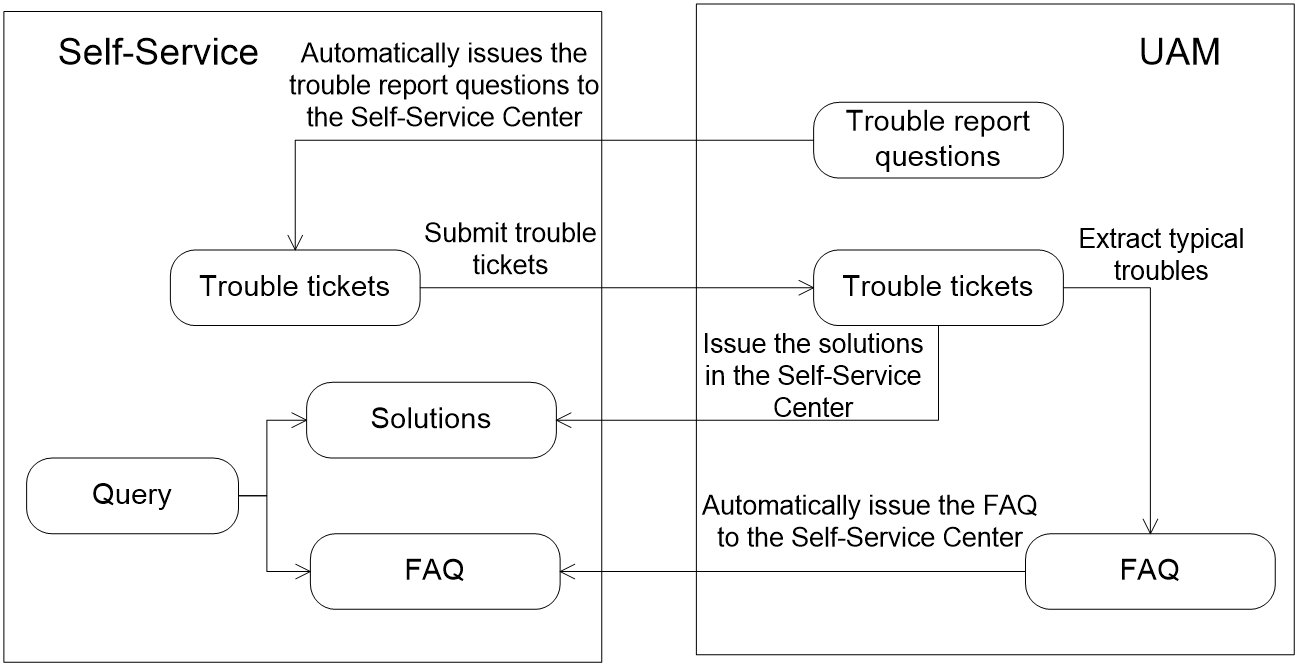
Managing report questions
Trouble report questions management lets an operator customize issues in a trouble ticket. To describe a problem, an endpoint user needs to answer several questions to provide information needed for analyzing, locating, and solving the issue.
Trouble report questions include the following types of questions:
· Integer-type trouble report question—Uses an integer to describe the trouble conditions, for example, the number of troubles per week.
· String-type trouble report question—Typically used in a scenario where an endpoint user must describe the trouble.
· Check box-type trouble report question—Typically used in a scenario where a fixed trouble has multiple options. For example, whether the gateway can be pinged or whether the DNS server can be pinged when the network fails.
· List-type trouble report question—Typically used in a scenario with one or more fixed issues, for example, whether the trouble occurs in an office area, a lab area, or a restroom.
Accessing the trouble report question list page
1. Click the User ab.
2. From the navigation tree, select Access User > Trouble Report > Custom TSHOOT Field.
The list includes trouble report questions.
Trouble report question list contents
¡ Question—Name of the trouble report question. The Question field is displayed in the trouble ticket.
¡ UI Element Type—Type of trouble report question, which can be integer, string, check box, or list. If the UI element type is integer, the endpoint user can enter an integer when reporting a trouble. If the UI element type is string, the endpoint user can enter a string. If the UI element type is check box, the endpoint user can only select or deselect a trouble. If the UI element type is a list, the endpoint user can only select a value in the list.
¡ Priority—This column has two icons, Up ![]() and Down
and Down ![]() .
Click the Up icon
.
Click the Up icon ![]() to increase the
priority of the trouble report question. Click the Down
icon
to increase the
priority of the trouble report question. Click the Down
icon ![]() to decrease the priority of the trouble report question. You cannot
increase the priority of the trouble report question in the first line. The Up icon
to decrease the priority of the trouble report question. You cannot
increase the priority of the trouble report question in the first line. The Up icon ![]() in the first line
is grayed. You cannot decrease the priority of the trouble report question in
the last line. The Down icon
in the first line
is grayed. You cannot decrease the priority of the trouble report question in
the last line. The Down icon ![]() in
the last line is grayed. In the trouble ticket, the trouble report questions
are displayed in descending priority order.
in
the last line is grayed. In the trouble ticket, the trouble report questions
are displayed in descending priority order.
¡ Details—Click the Details icon ![]() to view the detailed
information about the trouble report question.
to view the detailed
information about the trouble report question.
¡ Modify—Click the Modify icon ![]() to modify the trouble report question.
to modify the trouble report question.
¡ Delete—Click the Delete icon ![]() to delete the trouble report question.
to delete the trouble report question.
3. Click Refresh on top of the list to view the latest trouble report questions.
Viewing trouble report question details
1. Access the Custom TSHOOT Field page.
2. Click the Details
icon ![]() for the trouble
report question whose details you want to view.
for the trouble
report question whose details you want to view.
The Trouble Report Question Details page opens. The trouble report question details vary with the UI element type.
¡ The Integer type supports the following parameters:
- Question—Name of the trouble report question. The Question field is displayed in the trouble ticket.
- Priority—Priority of the trouble report question. In the trouble ticket, the trouble report questions are displayed in descending priority order.
- UI Element Type—Type of the trouble report question. When this field is integer, an endpoint user must enter an integer when reporting a trouble.
- Default—Default value of the trouble report question. This field can be empty.
- Minimum Value—Minimum value allowed.
- Maximum Value—Maximum value allowed.
¡ The String type supports the following parameters:
- Question—Name of the trouble report question. The Question field is displayed in the trouble ticket.
- Priority—Priority of the trouble report question. In the trouble ticket, the trouble report questions are displayed in descending priority order.
- UI Element Type—Type of the trouble report question. When this field is string, an endpoint user must enter a string when reporting a trouble.
- Default—Default value of the trouble report question. This field can be empty.
- Max Length—Maximum number of characters allowed.
¡ The Check box type supports the following parameters:
- Question—Name of the trouble report question. The Question field is displayed in the trouble ticket.
- Priority—Priority of the trouble report question. In the trouble ticket, the trouble report questions are displayed in descending priority order.
- UI Element Type—Type of the trouble report question. When this field is check box, an endpoint user must select or unselect a trouble when reporting a trouble.
- Default—Default value of the trouble report question, which can be Selected or Unselected.
¡ The Drop Down List type supports the following parameters:
- Question—Name of the trouble report question. The Question field is displayed in the trouble ticket.
- Priority—Priority of the trouble report question. In the trouble ticket, the trouble report questions are displayed in descending priority order.
- UI Element Type—Type of the trouble report question. When this field is list, an endpoint user must select a value in the list when reporting a trouble.
- Default—Default value of the trouble report question. This field can be empty.
- Options List—Available options in the list.
3. Click Back to return to the Trouble Report Questions List page.
Adding a trouble report question
1. Access the Custom TSHOOT Field page.
2. Click Add in the Trouble Report Questions List area.
The trouble report question parameters vary with the UI element type.
¡ The Integer-type trouble report question supports the following parameters:
- Question—Enter the trouble report question name. The name must be unique in UAM. The Question field is displayed in the trouble ticket.
- UI Element Type—Select a type for the trouble report question from the list. When this field is Integer, an endpoint user must enter an integer when reporting a trouble.
- Default—Enter the default value of the trouble report question. This field can be empty.
- Minimum Value—Enter the minimum value allowed to enter for the trouble report question.
- Maximum Value—Enter the maximum value allowed to enter for the trouble report question.
¡ The String-type trouble report question supports the following parameters:
- Question—Enter the trouble report question name. The name must be unique in UAM. The Question field is displayed in the trouble ticket.
- UI Element Type—Select a type for the trouble report question from the list. When this field is String, an endpoint user must enter a string when reporting a trouble.
- Default—Enter the default value of the trouble report question. This field can be empty.
- Max Length—Enter the maximum number of characters in the string for the trouble report question.
¡ The Check box-type trouble report question supports the following parameters:
- Question—Enter the trouble report question name. The name must be unique in UAM. The Question field is displayed in the trouble ticket.
- UI Element Type—Select a type for the trouble report question from the list. When this field is Check Box, an endpoint user must select or unselect a trouble when reporting a trouble.
- Default—Select the default value of the trouble report question, which can be Selected or Unselected.
¡ The Drop down list-type trouble report question supports the following parameters:
- Question—Enter the trouble report question name. The name must be unique in UAM. The Question field is displayed in the trouble ticket.
- UI Element Type—Select a type for the trouble report question from the list. When this field is Drop-Down List, an endpoint user must select a value in the list when reporting a trouble.
- Default—Enter the default value of the trouble report question. The default value, if specified, must be in the list. This field can be empty.
- Options List—Displays all available options in the list. In the trouble ticket, the available options are displayed in the list in the same order.
3. Do one of the following:
¡ To add an option to the options list, enter a value in the Option field and click Add under the Option field.
¡ To modify an option in the options list, select the option to display the option in the Option field, modify the option, and click Modify under the Modify field.
¡ To delete an option from the options list, select the option and click Delete under the Option field.
¡ To move up an option in the options list, select the option and click Up under the Options List field. You cannot move up the option on the top of the list.
¡ To move down an option in the options list, select the option and click Down under the Options List field. You cannot move down the option on the bottom of the list.
¡ To configure an option in the options list as the default value, select the option and click Default under the Options List field.
When the endpoint user logs in to the Self-Service Center to submit a trouble ticket, the trouble report question is displayed in the Self-troubleshooting area.
Modifying a trouble report question
1. Access the Custom TSHOOT Field page.
2. Click the Modify
icon ![]() for the trouble report question you want to modify.
for the trouble report question you want to modify.
3. Modify the parameters except the UI element type. For more information, see "Adding a trouble report question."
Adjusting the priority of a trouble report question
The priority values of trouble report questions determine the order in which the trouble report questions are displayed in the trouble ticket. In the trouble ticket, the trouble report questions are displayed in descending priority order.
Adjusting the priority values of trouble report questions does not change the order of the existing trouble report questions in the trouble ticket.
To adjust the priority of a trouble report question:
1. Access the Custom TSHOOT Field page.
2. Click the Up
icon ![]() for a trouble report question to increase the priority of the
trouble report question, and click the Down icon
for a trouble report question to increase the priority of the
trouble report question, and click the Down icon ![]() for a trouble
report question to decrease the priority of the trouble report question.
for a trouble
report question to decrease the priority of the trouble report question.
You cannot increase the priority of the
trouble report question in the first line. The Up icon ![]() in
the first line is grayed. You cannot decrease the priority of the trouble
report question in the last line. The Down icon
in
the first line is grayed. You cannot decrease the priority of the trouble
report question in the last line. The Down icon ![]() in
the last line is grayed.
in
the last line is grayed.
Deleting a trouble report question
Deleting a trouble report question does not affect the existing trouble report questions in the trouble ticket.
To delete a trouble report question:
1. Access the Custom TSHOOT Field page.
2. Click the Delete
icon ![]() for the trouble report question you want to delete.
for the trouble report question you want to delete.
A confirmation dialog box opens.
Managing trouble tickets
By submitting a trouble ticket, an endpoint user can begin the trouble ticket workflow to resolve a network problem.
Trouble ticket contents
A completed trouble ticket contains the following contents:
· Basic information—Such as the trouble ticket ID, status, times, and the endpoint user contact information.
· Trouble report questions—Defined by the operator to help the endpoint user provide useful trouble information. For information about adding a trouble report question, see "Managing report questions."
· Trouble information—Includes the trouble summary, the trouble description, the solution, and any attachments.
¡ The endpoint user fills in the trouble summary and trouble description.
¡ The operator fills in the solution and can add up to 10 attachments.
Trouble ticket attachments
The operator can add up to 10 attachments to help the endpoint user solve the trouble. The attachments can be pictures or documents.
The following restrictions apply to attachments:
· File extension—PNG, JPG, JPEG, GIF, LOG, TXT, ZIP, or RAR.
· File name maximum length (including file extension)—Cannot exceed 80 characters.
· Maximum size of each attachment—1MB.
Trouble ticket workflow
1. When an endpoint user encounters a network trouble, the endpoint user logs in to the Self-Service Center and submits a trouble ticket.
2. In UAM, the operator checks the trouble tickets submitted by endpoint users, analyzes and locates the troubles, and fills in the solutions in the trouble tickets.
3. The endpoint user checks the trouble ticket in the Self-Service Center to get the solution for the trouble.
Managing trouble tickets in the Self-Service Center
Logging into the Self-Service Center
1. Open the Web browser, and enter http://ip:port/selfservice or https://ip:port/selfservice in the address bar to open the Self-Service Center login page, where ip is the IP address of the server with the Self-Service component installed and port is the HTTP or HTTPS service port number provided by the Self-Service component.
2. Enter the user name, password, and verification code.
3. Select Ordinary user from the User Type list, and click Login.
For more information about the Self-Service Center, see "Using the user self-service."
Submitting a trouble ticket
1. From the navigation tree, select Trouble Management > Submit Trouble Ticket.
This menu option is displayed only when Trouble Report Service is enabled in the system parameters for user access policies.
2. Configure the following basic information:
¡ Account Name/User Name—Account name and user name of the endpoint user who has logged in to the Self-Service Center. The two fields are automatically obtained by the system. The endpoint user does not need to enter the account name and user name.
¡ Telephone—Enter a telephone number, so that the network administrator can contact the endpoint user.
¡ Contact Address—Enter the contact address of the endpoint user. When the trouble is hard to solve, the network administrator can go to the contact address to solve the trouble in the field.
¡ Appointment Time—If the network administrator will solve the trouble in the field, enter the appointment time.
¡ Trouble Occurred at—Click the Calendar icon ![]() , select the date
when the trouble occurred, and enter the time when the trouble occurred.
, select the date
when the trouble occurred, and enter the time when the trouble occurred.
3. Select or enter the related information in the Self-troubleshooting area.
The Self-troubleshooting area displays the trouble report questions defined in UAM. The endpoint user can specify information for each trouble report question.
4. Configure the trouble information as a supplementary to the Self-troubleshooting area:
¡ Trouble Summary—Enter summary information of the trouble.
¡ Trouble Description—Enter detailed information of the trouble.
Viewing a trouble ticket
From the navigation tree, select Trouble Management > Query Trouble Tickets.
The trouble ticket list includes the following contents:
· Trouble Ticket ID—Trouble ticket ID, which is automatically assigned by the system.
· Reported at—Time when the endpoint user reported the trouble.
· Trouble Summary—Summary information of the trouble.
· Status—State of the trouble ticket:
- Handled—The operator has handled the trouble and replied to the endpoint user.
¡ Not Handled—The operator has not handled the trouble ticket.
¡ Fed Back—The endpoint user has submitted the feedback for the trouble ticket.
· Handled at—Time when the operator completed handling the trouble ticket. This field is empty for a trouble ticket in the Not Handled state.
· Satisfaction Degree—User evaluation for handling of the trouble ticket: Outstanding, Above Average, Satisfactory, Below Average, or Unsatisfactory. This field is empty if the trouble ticket is not handled or not fed back.
· Adoption Status—Whether the solution to the trouble ticket is adopted: Adopted, Partially Adopted, or Unadopted. This field is empty if the trouble ticket is not handled or not fed back.
· Feedback—Click the Feedback icon ![]() to submit a feedback for the trouble ticket.
This field is empty if the trouble ticket is not handled or already fed back.
to submit a feedback for the trouble ticket.
This field is empty if the trouble ticket is not handled or already fed back.
· Delete—Click the Delete icon ![]() for a trouble ticket
to delete it. The Delete icon
for a trouble ticket
to delete it. The Delete icon ![]() does not appear for a trouble ticket in the
Handled state.
does not appear for a trouble ticket in the
Handled state.
· Details—Click the Details icon ![]() to view the detailed information about the
trouble ticket.
to view the detailed information about the
trouble ticket.
Viewing trouble ticket details
1. From the navigation tree, select Trouble Management > Query Trouble Tickets.
All trouble tickets are displayed on the trouble ticket list.
2. Click the Details
icon ![]() for the trouble
ticket whose detailed information you want to view.
for the trouble
ticket whose detailed information you want to view.
The Trouble Ticket Details page opens.
Basic Information
¡ Trouble Ticket ID—Trouble ticket ID, which is automatically assigned by the system to identify the trouble ticket.
¡ Reported at—Time when the endpoint user reported the trouble.
¡ Status—State of the trouble ticket:
- Handled—The operator has handled the trouble and replied to the endpoint user.
- Not Handled—The operator has not handled the trouble ticket.
- Fed Back—The endpoint user has submitted the feedback for the trouble ticket.
¡ Account Name/User Name—Account name and user name of the endpoint user who submitted the trouble ticket.
¡ Telephone—Telephone number of the endpoint user, through which the network administrator can contact the endpoint user.
¡ Contact Address—Contact address of the endpoint user. When the trouble is difficult to solve, the network administrator can use the contact address to solve the trouble.
¡ Appointment Time—Appointment time when the network administrator will solve the trouble.
¡ Trouble Occurred at—Time when the trouble occurred.
Trouble Symptom
Each trouble symptom is defined by the endpoint user. For information about defining trouble report questions in UAM, see "Managing report questions."
Trouble Information
¡ Trouble Summary—Summary information of the trouble, which is entered by the endpoint user.
¡ Trouble Description—Detailed information of the trouble, which is entered by the endpoint user.
¡ Solution—Solution for the trouble, which is entered by the operator. This field is empty for a trouble ticket in the Not Handled state.
¡ Attachments—The attachments that the operator adds to help the endpoint user solve the trouble. The attachments can be pictures or documents. Click the name link for the attachment information to open or save the attachment. This field is not displayed when the operator did not add any attachment information.
¡ Operator—The operator that solves the trouble. This field is empty for a trouble ticket in the Not Handled state.
¡ Handled at—Time when the operator completed handling the trouble ticket. This field is empty for a trouble ticket in the Not Handled state.
This area displays the feedback information submitted by the endpoint user. It does not appear if the trouble ticket is not handled or not fed back.
¡ Satisfaction Degree—User evaluation for handling of the trouble ticket: Outstanding, Above Average, Satisfactory, Below Average, or Unsatisfactory.
¡ Adoption Status—Whether the solution to the trouble ticket is adopted: Adopted, Partially Adopted, or Unadopted.
¡ Feedback—Feedback submitted by the endpoint user for the trouble ticket.
¡ Fed Back at—Time when the endpoint user submitted the feedback.
3. Click Back to return to the Query Trouble Tickets page.
Submitting a feedback
The endpoint user can submit the feedback for a trouble ticket in the Handled state.
To submit a feedback:
1. From the navigation tree, select Trouble Management > Query Trouble Tickets.
All trouble tickets are displayed on the trouble ticket list.
2. Click the Feedback icon ![]() for the handled trouble ticket for which you want to submit the feedback.
for the handled trouble ticket for which you want to submit the feedback.
The Submit Feedback page opens.
3. Configure the following parameters:
¡ Satisfaction Degree—Select an evaluation result from the list: Outstanding, Above Average, Satisfactory, Below Average, or Unsatisfactory.
¡ Adoption Status—Select whether the solution to the trouble ticket is adopted: Adopted, Partially Adopted, or Unadopted.
¡ Feedback—Enter other feedback information for the trouble ticket.
4. Click OK.
Deleting a trouble ticket
The endpoint user cannot delete a trouble ticket in the Handled or Fed Back state. Such trouble tickets must be deleted in UAM.
To delete a trouble ticket:
1. In the Self-Service Center, select Trouble Management > Query Trouble Tickets from the navigation tree.
All trouble tickets on the trouble ticket list are displayed.
2. Click the Delete
icon ![]() for the trouble ticket you want to delete.
for the trouble ticket you want to delete.
A confirmation dialog box opens.
Managing trouble tickets in UAM
In UAM, the operator checks the trouble tickets submitted by endpoint users, analyzes and locates the troubles, and fills the solutions in the trouble tickets.
Accessing the trouble ticket list page
1. Click the User tab.
2. From the navigation tree, select Access User > Trouble Report > Trouble Ticket.
All trouble tickets on the trouble ticket list are displayed.
Trouble ticket list contents
¡ Ticket ID—Trouble ticket ID, which is automatically assigned by the system to identify the trouble ticket.
¡ Account—Account name of the endpoint user who submits the trouble ticket. Click the account name link to display the Access Account Info page.
¡ Trouble Summary—Summary information of the trouble.
¡ Reported at—Time when the endpoint user reported the trouble.
¡ Typical—Whether the trouble ticket is typical. This field displays Yes only after the IMC operator configures the trouble ticket as typical.
¡ Status—State of the trouble ticket:
- Handled—The operator has handled the trouble and replied to the endpoint user.
- Not Handled—The operator has not handled the trouble ticket.
- Fed Back—The endpoint user has submitted the feedback for the trouble ticket.
¡ Satisfaction Degree—User evaluation for handling of the trouble ticket: Outstanding, Above Average, Satisfactory, Below Average, or Unsatisfactory. This field is empty if the trouble ticket is not handled or not fed back.
¡ Adoption Status—Whether the solution to the trouble ticket is adopted: Adopted, Partially Adopted, or Unadopted. This field is empty if the trouble ticket is not handled or not fed back.
¡ Handle—Click the Handle icon ![]() to handle the trouble ticket. The Handle icon
to handle the trouble ticket. The Handle icon ![]() does not appear when the trouble ticket is in
the Handled state.
does not appear when the trouble ticket is in
the Handled state.
¡ Details—Click
the Details icon ![]() to view the detailed information about the
trouble ticket.
to view the detailed information about the
trouble ticket.
Performing a basic query for trouble tickets
1. Access the Trouble Ticket page.
2. Click the Basic Query link on the upper right side of the Query Trouble Tickets area.
You can perform a basic query if you see Advanced Query on the upper right side of the Query Trouble Tickets area.
3. Specify one or more of the following query criteria:
¡ Ticket ID—Enter a partial or complete trouble ticket ID. For example, if you enter 1, all ticket IDs that contain 1 are matched.
¡ Status—Select a trouble ticket state from the list: Handled, To Be Handled, or Fed Back.
¡ Account Name—Enter a partial or complete account name of the endpoint user who submitted the trouble ticket. For example, if you enter lab, all account names that contain lab are matched.
¡ Typical—Select Yes or No from the list.
The query ignores empty fields.
4. Click Query.
The list includes all trouble tickets matching the query criteria.
5. To clear the query criteria, click Reset.
The list includes all the trouble tickets.
Performing an advanced query for trouble tickets
1. Access the Trouble Ticket List page.
2. Click the Advanced Query link on the upper right side of the Query Trouble Tickets area.
You can perform an advanced query if you see Basic Query on the upper right side of the Query Trouble Tickets area.
3. Specify one or more of the following query criteria:
¡ Ticket ID—Enter a partial or complete trouble ticket ID. For example, if you enter 1, all ticket IDs that contain 1 are matched.
¡ Account Name—Enter a partial or complete account name of the endpoint user who submitted the trouble ticket. For example, if you enter lab, all account names that contain lab are matched.
¡ User Name—Enter a partial or complete user name of the endpoint user who submitted the trouble ticket. For example, if you enter office, all user names that contain office are matched.
¡ Contact Phone Number—Enter a partial or complete contact telephone number of the endpoint user. For example, if you enter 0, all contact telephone numbers that contain 0 are matched.
¡ Status—Select a trouble ticket state from the list: Handled, To Be Handled, or Fed Back.
¡ Contact Address—Enter a partial or complete contact address of the endpoint user. For example, if you enter building-2, all contact addresses that contain building-2 are matched.
¡ Reported From/To—Enter the time range
when the trouble ticket was reported, or click the Calendar icon ![]() to select the
time range. The time range must be in the format of YYYY-MM-DD.
to select the
time range. The time range must be in the format of YYYY-MM-DD.
¡ Trouble Time From/To—Enter the time
range when the trouble occurred, or click the Calendar icon ![]() to select the
time range. The time range must be in the format of YYYY-MM-DD.
to select the
time range. The time range must be in the format of YYYY-MM-DD.
¡ Summary—Enter a partial or complete summary of the trouble. For example, if you enter disconnect, all summary information that contains disconnect is matched.
¡ Trouble Description—Enter a partial or complete description of the trouble. For example, if you enter server error, all descriptions that contain server error are matched.
¡ Operator—Enter a partial or complete operator ID of the operator who solves the trouble. For example, if you enter lab, all operator IDs that contain lab are matched.
¡ Typical—Select Yes or No from the list.
¡ Handled From/To—Enter the time range
when the trouble ticket was handled, or click the Calendar icon ![]() to select the
time range. The time range must be in the format of YYYY-MM-DD.
to select the
time range. The time range must be in the format of YYYY-MM-DD.
¡ Solution—Enter a partial or complete solution of the trouble ticket. For example, if you enter reinstall, all solutions that contain reinstall are matched.
¡ Satisfaction Degree—Select an evaluation result from the list: Outstanding, Above Average, Satisfactory, Below Average, or Unsatisfactory.
¡ Adoption Status—Select whether the solution to the trouble ticket is adopted: Adopted, Partially Adopted, or Unadopted.
¡ Feedback From/To—Enter the time range when feedbacks are submitted for the trouble tickets, or click the Calendar icon ![]() to select the time range. The time range must be in the format of YYYY-MM-DD.
to select the time range. The time range must be in the format of YYYY-MM-DD.
¡ Feedback—Enter a partial or complete keyword in the user feedback information. For example, if you enter txt, all feedback information that contains txt is matched.
The query ignores empty fields.
The list includes all trouble tickets matching the query criteria.
5. To clear the query criteria, click Reset.
The list includes all the trouble tickets.
Viewing trouble ticket details
1. Access the Trouble Ticket List page.
2. Click the Details
icon ![]() for the trouble ticket whose details you want to view.
for the trouble ticket whose details you want to view.
The Trouble Ticket Details page opens.
3. The trouble ticket details page displays the following contents:
Basic Information
¡ Trouble Ticket ID—Trouble ticket ID, which is automatically assigned by the system to identify the trouble ticket.
¡ Reported at—Time when the endpoint user reported the trouble.
¡ Status—State of the trouble ticket:
- Handled—The operator has handled the trouble and replied to the endpoint user.
- Not Handled—The operator has not handled the trouble ticket.
- Fed Back—The endpoint user has submitted the feedback for the trouble ticket.
¡ Account Name/User Name—Account name and user name of the endpoint user who submitted the trouble ticket.
¡ Contact Phone Number—Telephone number of the endpoint user, through which the network administrator can contact the endpoint user.
¡ Contact Address—Contact address of the endpoint user. When the trouble is complicated, the network administrator can go to the contact address to solve the trouble in the field.
¡ Appointment Time—Appointment time when the network administrator will solve the trouble in the field.
¡ Trouble Occurred at—Time when the trouble occurred.
¡ Typical—Indicates whether the trouble ticket is configured as typical. This field is Yes only after the IMC operator configures the trouble ticket as typical.
¡ Added to FAQ—Indicates whether the trouble ticket is added to the FAQ. This field is Yes only after the IMC operator adds the trouble ticket to the FAQ.
Trouble Details
Each trouble symptom is set by the endpoint user. For information about defining trouble report questions in UAM, see "Managing report questions."
Trouble Information
¡ Trouble Summary—Summary information of the trouble, which is entered by the endpoint user.
¡ Trouble Description—Detailed information of the trouble, which is entered by the endpoint user.
¡ Solution—Solution for the trouble, which is entered by the operator. This field is empty for a trouble ticket in the To Be Handled state.
¡ Operator—The operator who solves the trouble. This field is empty for a trouble ticket in the To Be Handled state.
¡ Handled at—Time when the operator completed handling the trouble ticket. This field is empty for a trouble ticket in the To Be Handled state.
Feedback
This area displays the feedback information submitted by the endpoint user. It does not appear if the trouble ticket is not handled or not fed back.
¡ Satisfaction Degree—User evaluation for handling of the trouble ticket: Outstanding, Above Average, Satisfactory, Below Average, or Unsatisfactory.
¡ Adoption Status—Whether the solution to the trouble ticket is adopted: Adopted, Partially Adopted, or Unadopted.
¡ Feedback—Feedback submitted by the endpoint user for the trouble ticket.
¡ Fed Back at—Time when the endpoint user submitted the feedback.
4. Click Set to Typical to configure the trouble ticket as a typical trouble ticket. The Set to Typical button is not displayed for a trouble ticket in To Be Handled state.
5. Click Add to FAQ to display the page for adding the trouble ticket to the FAQ.
The page automatically reads the trouble summary, trouble description, and solution of the trouble ticket and uses the three fields as the summary, symptom, and solution of an FAQ. Adding a trouble ticket to the FAQ is similar to adding an FAQ. For more information, see "Managing FAQs." The Add to FAQ button is not displayed for a trouble ticket in the To Be Handled state.
6. Click Print to print the trouble ticket.
7. Click Back to return to the Trouble Ticket List page.
Handling a trouble ticket
1. Access the Trouble Ticket List page.
2. Click the Handle
icon ![]() for a trouble ticket in the To Be Handled
state. The Handle icon
for a trouble ticket in the To Be Handled
state. The Handle icon ![]() is not displayed for a trouble ticket in the Handled
state.
is not displayed for a trouble ticket in the Handled
state.
3. You cannot modify the basic information, trouble details, and trouble information of the trouble ticket, which are used for helping the operator to analyze and locate the trouble.
Basic Information
¡ Ticket ID—Trouble ticket ID, which is automatically assigned by the system to identify the trouble ticket.
¡ Reported at—Time when the endpoint user reported the trouble.
¡ Status—State of the trouble ticket. The state of a trouble ticket that has not been handled is To Be Handled.
¡ Account Name/User Name—Account name and user name of the endpoint user who submitted the trouble ticket.
¡ Contact Phone Number—Telephone number of the endpoint user, through which the network administrator can contact the endpoint user.
¡ Contact Address—Contact address of the endpoint user. When the trouble is hard to solve, the network administrator can go to the contact address to solve the trouble in the field.
¡ Appointment Time—Appointment time when the network administrator will solve the trouble in the field.
¡ Trouble Occurred at—Time when the trouble occurred.
¡ Typical—A trouble ticket in the To Be Handled state cannot be configured as typical. This field is Yes only after the IMC operator configures the trouble ticket as typical.
¡ Added to FAQ—Any trouble ticket in the To Be Handled state cannot be added to FAQ. This field is Yes only after the IMC operator adds the trouble ticket to the FAQ.
Trouble Details
Each trouble symptom is set by the endpoint user. For information about defining trouble report questions in UAM, see "Managing report questions."
Trouble Information
¡ Summary—Summary information of the trouble, which is entered by the endpoint user.
¡ Trouble Description—Detailed information about the trouble, which is entered by the endpoint user.
4. Enter the solution of the trouble ticket in the Solution field. As a best practice, enter the methods and procedures for handling the trouble ticket.
5. Add attachments to the trouble ticket:
a. Click Add. The page is automatically refreshed.
b. Click Browse, and select a local file or a file saved on any other host in the network.
c. Repeat steps a and b to add multiple attachments. You can add up to 10 attachments.
d. Click Delete to the right of an attachment to delete the attachment.
6. Select whether to configure the trouble ticket as a typical trouble ticket.
Select the Typical box to configure the trouble ticket as a typical trouble ticket. Clear the box to cancel the typical trouble ticket configuration.
7. If you want to print the trouble ticket, click Print to display the page for previewing the trouble ticket printout and click Print on the upper right of the page. The printout does not include the trouble ticket solution.
8. Click OK.
Deleting a trouble ticket
Trouble tickets that are deleted from UAM no longer appear in the Self-Service Center.
To delete a trouble ticket:
1. Access the Trouble Ticket List page.
2. Select one or more trouble tickets you want to delete.
3. Click Delete.
A confirmation dialog box opens.
Managing FAQs
Collecting and grouping the frequently asked questions and releasing them to endpoint users can reduce maintenance costs, decrease troubleshooting times, and improve efficiency.
FAQ management and usage include the following:
· The operator configures the FAQ in UAM.
· The endpoint user queries and views the FAQ in the Self-Service Center.
FAQ attachments
Both the symptom and solution of an FAQ can contain attachments. If you cannot describe the symptom or solution, you can add pictures or documents to help describe the symptom or solution.
The following restrictions apply to attachments:
· File extension—PNG, JPG, JPEG, GIF, LOG, TXT, ZIP, or RAR.
· File name maximum length (including file extension)—Cannot exceed 80 characters.
· Maximum size of each attachment—1MB.
· Maximum number attachments—The symptom can include up to three attachments. The solution can include up to 10 attachments.
Managing FAQs in UAM
Accessing the FAQ List page
1. Click the User tab.
2. From the navigation tree, select Access User > Trouble Report > FAQ.
All FAQs are displayed on the FAQ list.
FAQ list contents
¡ No.—FAQ number, which is automatically assigned by the system.
¡ Summary—Brief description of the FAQ.
¡ Details—Click
the Details icon ![]() to view detailed information about the FAQ.
to view detailed information about the FAQ.
¡ Modify—Click the Modify icon ![]() to modify the FAQ.
to modify the FAQ.
¡ Delete—Click the Delete icon ![]() to delete the FAQ.
to delete the FAQ.
Querying FAQs
1. Access the FAQ List page.
2. Enter a partial or complete keyword in the Keyword field as the query criterion.
The keyword is used to match the summary, symptom, and solution of an FAQ. For example, if you enter lab, all FAQs whose summary, symptom, or solution contain lab are matched.
3. Click Query.
The list includes all FAQs matching the query criterion.
To clear the query criterion, click Reset. The list includes all FAQs.
Viewing FAQ details
1. Access the FAQ List page.
2. Click the Details
icon ![]() for the FAQ whose details you want to view.
for the FAQ whose details you want to view.
The Details page opens.
¡ No.—FAQ number, which is automatically assigned by the system.
¡ Creation Time—Time when the FAQ is created.
¡ Summary—Brief description of the FAQ.
¡ Symptom—Detailed information of the trouble.
¡ Attachments—Both the symptom and solution of an FAQ can contain attachments. If you cannot describe the symptom or solution, you can add pictures or documents to describe the symptom or solution. Click the name link for an attachment to open or save the attachment. This field is not displayed when no attachment is added.
¡ Solution—Solution to the trouble.
3. Click Back to return to the FAQ List page.
Adding an FAQ
A newly-added FAQ is automatically displayed in the Self-Service Center. Any endpoint user logging in to the Self-Service Center can view the FAQ.
To add an FAQ:
1. Access the FAQ List page.
2. Click Add in the FAQ List area.
3. Enter the brief description of the FAQ in the Summary field.
The summary of an FAQ must be unique.
4. Enter the detailed information of the trouble in the Symptom field.
5. Add attachments for the symptom:
a. Click Add under the Symptom field. The page is automatically refreshed.
b. Click Browse, and select a local file or a file saved on any other host in the network.
c. Repeat the previous steps to add multiple attachments. You can add up to three attachments.
d. Click Delete to the right of an attachment to delete the attachment.
6. Enter the solution for the FAQ in the Solution field.
7. Add attachments for the solution:
a. Click Add under the Solution field. The page is automatically refreshed.
b. Click Browse, and select a local file or a file saved on any other host in the network.
c. Repeat steps a and b to add multiple attachments. You can add up to 10 attachments.
d. Click Delete to the right of an attachment to delete the attachment.
8. Click OK.
The system automatically numbers the FAQ. If n FAQ already exists in the system, the system numbers the newly added FAQ as n+1.
Modifying an FAQ
1. Access the FAQ List page.
2. Click the Modify
icon ![]() for the FAQ you want to modify.
for the FAQ you want to modify.
3. Modify the number of the FAQ.
After you modify the number of an FAQ, the system automatically re-numbers the affected FAQ. Suppose five FAQ A, B, C, D, and E numbered 1, 2, 3, 4, and 5 exist in the system. When you modify the number of FAQ D from 4 to 5 or a number greater than 5, the system automatically numbers FAQ A, B, C, E, and D as 1, 2, 3, 4, and 5. When you modify the number of FAQ D from 4 to 2, the system automatically numbers FAQ A, D, B, C, and E as 1, 2, 3, 4, and 5.
4. Modify the brief description of the FAQ in the Summary field.
The summary of an FAQ must be unique. Modify the detailed information of the trouble in the Symptom field.
5. Add attachments for the symptom:
a. Click Add under the Symptom field. The page is automatically refreshed.
b. Click Browse, and select a local file or a file saved on any other host in the network.
c. Repeat steps a and b to add multiple attachments. You can add up to three attachments.
d. Click Delete to the right of an attachment to delete the attachment.
6. Modify the solution for the FAQ in the Solution field.
7. Add attachments for the solution:
a. Click Add under the Solution field. The page is automatically refreshed.
b. Click Browse, and select a local file or a file saved on any other host in the network.
c. Repeat steps a and b to add multiple attachments. You can add up to 10 attachments.
d. Click Delete to the right of an attachment to delete the attachment.
8. Click OK.
Deleting an FAQ
FAQs that are deleted from UAM no longer appear in the Self-Service Center.
To delete an FAQ:
1. Access the FAQ List page.
2. Click the Delete
icon ![]() for the FAQ you want to delete.
for the FAQ you want to delete.
A confirmation dialog box opens.
Using FAQs in the Self-Service Center
When an endpoint user encounters a network problem, the endpoint user can log in to the Self-Service Center to view the FAQ and find a solution for the network trouble. If the endpoint user fails to find a solution in the FAQ, the endpoint user can submit a trouble ticket. For more information about submitting a trouble ticket, see "Managing report questions."
To log in to the Self-Service Center:
1. Open the Web browser, and enter http://ip:port/selfservice or https://ip:port/selfservice in the address bar to open the self-service center login page, where ip is the IP address of the server with the Self-Service component installed and port is the HTTP or HTTPS service port number provided by the Self-Service component.
2. Enter the user name, password, and verification code, select Ordinary user from the User type list, and click Login to log in to the Self-Service Center.
For more information about the Self-Service Center, see "Using the user self-service."
Viewing FAQs
In the Self-Service Center, select Trouble Management > FAQ from the navigation tree.
All FAQs are displayed on the FAQ list.
FAQ list contents
· No.—FAQ number, which is automatically assigned by the system.
· Summary—Brief description of the FAQ.
· Details—Click the Details icon ![]() to view the detailed information about the FAQ.
to view the detailed information about the FAQ.
Querying FAQs
1. In the Self-Service Center, select Trouble Management > FAQ from the navigation tree.
All FAQs are displayed on the FAQ list.
2. Enter a partial or complete keyword in the Keyword field as the query criterion.
The keyword is used to match the summary, symptom, and solution of an FAQ. For example, if the endpoint user enters lab, all summary, symptom, or solution information containing lab are matched.
3. Click Query.
The list includes all FAQs matching the query criterion.
4. To clear the query criterion, click Reset.
The list includes all FAQs.
Viewing FAQ details
1. In the Self-Service Center, select Trouble Management > FAQ from the navigation tree.
All FAQs are displayed on the FAQ list.
2. Click the Details
icon ![]() for the FAQ whose details you want to view.
for the FAQ whose details you want to view.
The Details page opens.
3. The FAQ details page displays the following contents:
¡ No.—FAQ number, which is automatically assigned by the system to identify the FAQ.
¡ Creation Time—Time when the FAQ is created.
¡ Summary—Brief description of the FAQ.
¡ Symptom—Detailed information of the trouble.
¡ Attachments—Both the symptom and solution of an FAQ can contain attachments. Click the name link for an attachment to open or save the attachment. This field is not displayed when no attachment is added.
¡ Solution—Solution to the trouble.
4. Click Back to return to the FAQ list page.
Managing FAQs in the Guest Center
When an endpoint user encounters a network problem, the endpoint user can log in to the Guest Center to view the FAQs and find a solution to the network trouble.
To view the Guest Center FAQs:
1. Open the Web browser, and then enter http://ip:port/guest or https://ip:port/guest in the address bar to open the Guest Center login page.
The string ip is the IP address of the server with the Guest Center component installed. The string port is the HTTP or HTTPS service port number provided by the Guest Center component.
2. Click Login to log in to the Guest Center.
All FAQs are displayed in the FAQ list.
FAQ list contents
¡ No.—FAQ number, which is automatically assigned by the system.
¡ Summary—Brief description of the FAQ.
¡ Details—Click the Details icon ![]() to view the detailed information
about the FAQ.
to view the detailed information
about the FAQ.
Querying FAQs
See "Querying FAQs."
Viewing FAQ details
See "Viewing FAQ details."
Managing user groups and service groups
UAM supports decentralized management. With decentralized management, you can do the following:
· Create user groups and service groups, and assign operators to each group.
· Select a user group or service group for services, access users, or other configuration items, so that each configuration item can be managed only by the operators that are assigned to the group.
· Assign different privileges to UAM operator groups.
In UAM, guidelines are often used together. For example, you can:
· Grant viewing and modifying privileges to an operator group.
· Configure an operator in that operator group to manage a specific service group.
This combination allows operators to view and modify services in the service group, but it does not allow them to add new services to or delete services from the service group.
For more information about operator group management, see HPE Intelligent Management Center v7.3 Enterprise and Standard Platform Administrator Guide.
Managing user groups
User groups apply to all access users, including ordinary access users, LDAP users, guests, and mute terminal users. When creating or modifying access users, operators can assign the users to different user groups and grant management or viewing privileges of each user group to specific maintainers or viewers.
UAM supports multiple levels of user groups, so you can create lower-level groups for each user group. The group levels are not limited.
Accessing the User Group List page
1. Click the System tab.
2. From the navigation tree, select Group Management > User Group.
All user groups appear in the User Group List.
User Group List contents
¡ Group Name—Name of a user group. The user groups of the same level cannot have duplicate names. Click the name of a user group to view its details.
¡ Description—Description for a user group.
¡ User List—Click the User List icon ![]() to view users in the
user group.
to view users in the
user group.
¡ Subgroups—Click the Subgroups icon ![]() to view subgroups in
the user group.
to view subgroups in
the user group.
¡ Modify—Click the Modify icon ![]() to modify the user
group.
to modify the user
group.
¡ Delete—Click the Delete icon ![]() to delete the user
group.
to delete the user
group.
3. Click Refresh to view the latest user group list.
Viewing a subgroup
The system-defined user group Ungrouped does not contain any subgroups.
To view a subgroup:
1. Access the User Group List page.
2. Click the Subgroups
icon ![]() for a user group to view its subgroups, click the Subgroups icon
for a user group to view its subgroups, click the Subgroups icon ![]() of a subgroup to view
the lower-level subgroups, and so on.
of a subgroup to view
the lower-level subgroups, and so on.
User group list contents
¡ Group Name—Name of a subgroup. The subgroups of the same group cannot have duplicate names. Click the name of a subgroup to view its details.
¡ Description—Description for a subgroup.
¡ User List—Click the User List icon ![]() to view users in the
subgroup.
to view users in the
subgroup.
¡ Subgroups—Click the Subgroups icon ![]() to view lower-level
subgroups in the subgroup.
to view lower-level
subgroups in the subgroup.
¡ Modify—Click the Modify icon ![]() to modify the
subgroup.
to modify the
subgroup.
¡ Delete—Click the Delete icon ![]() to delete the
subgroup.
to delete the
subgroup.
3. Click Refresh to view the latest subgroup list.
Viewing user group details
Operators can view details of every user-defined user group, but they cannot view the details of the system-defined user group Ungrouped. For more information, see HPE Intelligent Management Center v7.3 Enterprise and Standard Platform Administrator Guide.
To view details of a user group:
1. Access the User Group List page.
2. Click the name of a user group to view its details.
Basic Info
¡ Group Name—Name of the user group.
¡ Description—Description for the user group.
Operators
The list includes all operators that can manage the user group.
¡ Login Name—Account name that an operator uses to log in to IMC. Click a login name to view detailed information about the operator.
¡ Full Name—Full name of the operator.
¡ Role—Role of the operator, which can be ADMIN, Maintenance, or Viewer. An administrator can manage all devices, users, and services, and also has the privilege to configure the IMC system. A maintainer can manage all devices, users, and services, but cannot configure the IMC system. A viewer can only view devices, users, and services.
¡ Manage All Groups—Whether or not the operator can manage all user groups. When you add an operator, select the Manage All Groups option to enable the operator to automatically manage all user groups and subgroups, including all existing ones and new ones created in the future.
¡ Description—Description for the operator for easy maintenance.
Service Applied for by the Group
This area is available only when the system parameter Apply for Service by User Group is enabled. For more information about system parameters, see "Configuring global system settings."
This area displays the services assigned to the current user group. The services will be automatically assigned to the users in the group at 00:20 the next day.
Service list contents
¡ Service Name—Click the name link to view its details. For service details, see "Viewing access service details."
¡ Service Suffix—Distinguishes services when endpoint users are authenticated.
¡ Status—Identifies whether the service is available. When you add or modify a user group, you cannot select an unavailable service.
3. To go back to the user group list, click Back.
Viewing subgroup details
1. Access the User Group List page.
2. Click the Subgroups
icon ![]() for a user group to view its subgroups, click the Subgroups icon
for a user group to view its subgroups, click the Subgroups icon ![]() of a subgroup to view
the lower-level subgroups, and so on.
of a subgroup to view
the lower-level subgroups, and so on.
3. Click the name of a subgroup to view its details.
Basic Info
¡ Group Name—Name of the subgroup.
¡ Description—Description for the subgroup.
Operators
The list includes all operators that can manage the subgroup.
¡ Login Name—Account name that an operator uses to log in to IMC. Click a login name to view the detailed information about the operator.
¡ Full Name—Full name of the operator.
¡ Role—Role of the operator, which can be ADMIN, Maintenance, or Viewer. An administrator can manage all devices, users, and services, and also has the privilege to configure the IMC system. A maintainer can manage all devices, users, and services, but cannot configure the IMC system. A viewer can only view devices, users, and services.
¡ Manage All Groups—Whether or not to allow the operator to manage all user groups. When you add an operator, select the Manage All Groups option to enable the operator to automatically manage all user groups and subgroups, including all existing ones and new ones created in the future.
¡ Description—Description for the operator for easy maintenance.
Service Applied for by the Group
This area is available only when the system parameter Apply for Service by User Group is enabled. For more information about system parameters, see "Configuring global system settings."
This area displays the services assigned to the current user group. The services will be automatically assigned to the users in the group at 00:20 the next day.
Service list contents
¡ Service Name—Click the name link to view its details. For service details, see "Viewing access service details."
¡ Service Suffix—Distinguishes services when endpoint users are authenticated.
¡ Status—Identifies whether the service is available. When you add or modify a user group, you cannot select an unavailable service.
4. To go back to the subgroup list, click Back.
For more information, see HPE Intelligent Management Center v7.3 Enterprise and Standard Platform Administrator Guide.
Adding a user group
1. Access the User Group List page.
2. Click Add.
3. Configure the following basic information:
¡ Group Name—Enter the name of the user group, which cannot be an existing user group name.
¡ Description—Enter a description for the user group for easy maintenance.
4. Select the operators to manage the user group.
User groups do not inherit operators from upper-level groups. You must configure operators for individual user groups and lower-level groups.
UAM automatically grants management privileges of a new user group to administrators and maintainers that can manage all groups, and grants viewing privileges of a new user group to viewers that can view all groups.
5. Select the remaining maintainers and viewers as needed.
6. Select one or more services in the Service Applied for by the Group area.
The selected services will be assigned to all users belonging to the group at 00:20 the next day. Services in Unavailable state will not appear in the Service Applied for by the Group area. This area is available only when the system parameter Apply for Service by User Group is enabled. For more information about system parameters, see "Configuring global system settings."
7. Click OK.
Adding a subgroup
Operators can add subgroups to any user-defined user group, but cannot add a subgroup to the system-defined user group Ungrouped.
To add a subgroup:
1. Access the User Group List page.
2. Click the Subgroups
icon ![]() for a user group to view its subgroups, click the Subgroups icon
for a user group to view its subgroups, click the Subgroups icon ![]() of a subgroup to view
the lower-level subgroups, and so on.
of a subgroup to view
the lower-level subgroups, and so on.
3. Click Add.
4. Configure the following basic information:
¡ Group Name—Enter the name of the subgroup. Subgroups of the same group cannot have duplicate names.
¡ Description—Enter a description for the subgroup for easy maintenance.
5. Select the operators to manage the subgroup.
User groups do not inherit operators from upper-level groups. You must configure operators for individual user groups and lower-level groups.
UAM automatically grants management privileges of a new subgroup to administrators and maintainers that can manage all groups, and grants viewing privileges of a new subgroup to viewers that can view all groups.
6. Select the remaining maintainers and viewers as needed.
7. Select one or more services in the Service Applied for by the Group area.
The selected services will be assigned to all users belonging to the subgroup at 00:20 the next day. Services in Unavailable state will not appear in the Service Applied for by the Group area. This area is available only when the system parameter Apply for Service by User Group is enabled. For more information about system parameters, see "Configuring global system settings."
8. Click OK.
Modifying a user group
Operators can modify all user-defined user groups, but cannot modify the system-defined user group Ungrouped.
To modify a user group:
1. Access the User Group List page.
2. Click the Modify
icon ![]() for the user group you want to modify.
for the user group you want to modify.
3. Modify the user group parameters except the group name. For more information, see "Adding a user group."
4. Click OK.
Modifying a subgroup
1. Access the User Group List page.
2. Click the Subgroups
icon ![]() for a user group to view its subgroups, click the Subgroups icon
for a user group to view its subgroups, click the Subgroups icon ![]() of a subgroup to view
the lower-level subgroups, and so on.
of a subgroup to view
the lower-level subgroups, and so on.
3. Click the Modify
icon ![]() for the subgroup you want to modify.
for the subgroup you want to modify.
4. Modify the subgroup parameter except the group name. For more information, see "Adding a subgroup."
5. Click OK.
Deleting a user group
Operators can delete all user-defined user groups, but cannot delete the system-defined user group Ungrouped.
You cannot delete a user group that contains subgroups. Before you can delete a user group, you must first delete all of its lower-level subgroups.
When you delete a user group, all its users are automatically added to Ungrouped.
To delete a user group:
1. Access the User Group List page.
2. Click the Delete
icon ![]() for the user group you want to delete.
for the user group you want to delete.
A confirmation dialog box opens.
3. Click OK.
Deleting a subgroup
To delete a subgroup, you must first delete all lower-level subgroups it contains.
When you delete a subgroup, all its users are automatically added to Ungrouped.
To delete a subgroup:
1. Access the User Group List page.
2. Click the Subgroups
icon ![]() for a user group to view its subgroups, click the Subgroups icon
for a user group to view its subgroups, click the Subgroups icon ![]() of a subgroup to view
the lower-level subgroups, and so on.
of a subgroup to view
the lower-level subgroups, and so on.
3. Click the Delete
icon ![]() for the subgroup you want to delete.
for the subgroup you want to delete.
A confirmation dialog box opens.
4. Click OK.
Viewing users in a user group or subgroup
1. Access the User Group List page.
2. Click the Subgroups
icon ![]() for a user group to view its subgroups, click the Subgroups icon
for a user group to view its subgroups, click the Subgroups icon ![]() of a subgroup to view
the lower-level subgroups, and so on.
of a subgroup to view
the lower-level subgroups, and so on.
3. Click the User List
icon ![]() of the target user group or subgroup to view its users.
of the target user group or subgroup to view its users.
User List contents
¡ User Name—Name of a platform user. Click a user name to view the detailed information about a platform user.
¡ Identity Number—Identity number of a platform user.
¡ Open Account—Whether or not the platform has a self-service account.
¡ Account Name—Self-service account name of a platform user.
¡ Contact Address—Contact address of a platform user.
¡ Telephone—Telephone number of a platform user.
¡ Email—Email address of a platform user.
¡ User Group—User group to which a platform user belongs. Click a user group name to view the detailed information about the user group.
Querying users in a user group or subgroup
1. Access the User Group List page.
2. Click the Subgroups
icon ![]() for a user group to view its subgroups, click the Subgroups icon
for a user group to view its subgroups, click the Subgroups icon ![]() of a subgroup to view
the lower-level subgroups, and so on.
of a subgroup to view
the lower-level subgroups, and so on.
3. Click the User List
icon ![]() of the target user group or subgroup to view its users.
of the target user group or subgroup to view its users.
4. Specify one or more of the following query criteria:
¡ User Name—Enter a partial or complete platform user name. For example, if you enter x, all user names that contain x are matched.
¡ Identity Number—Enter a partial or complete identity number. For example, if you enter 5, all identity numbers that contain 5 are matched.
The query ignores empty fields.
5. Click Query.
The list includes all platform users matching the query criteria.
6. To clear the query criteria, click Reset.
The list includes all platform users.
Moving users between user groups
Services are automatically reassigned to the users moved to a new group at 00:00 the next day if the following conditions exist:
· The system parameter Apply for Service by User Group is enabled.
· The system parameter Apply Service Configuration Immediately is set to No.
Services are immediately reassigned to the users moved to a new group if the following conditions exist:
· The system parameter Apply for Service by User Group is enabled.
· The system parameter Apply Service Configuration Immediately is set to Yes.
For more information about system parameters, see "Configuring global system settings."
To move users between user groups:
1. Access the User Group List page.
2. Click the User List
icon ![]() of the group where the target users are located.
of the group where the target users are located.
If the target users are located in a
subgroup, click the Subgroups icon ![]() of
the upper-level user group, and then click the User List icon
of
the upper-level user group, and then click the User List icon ![]() of the group where the target users are
located.
of the group where the target users are
located.
3. Select users in the user list.
4. Click Move User.
5. Select the target group:
a. Click the Operator
Group icon ![]() in the Target Group area.
in the Target Group area.
b. Click Expand All to display all user groups and subgroups.
c. Select the target user group or subgroup.
d. Click OK.
6. Click OK.
Limiting the maximum number of users in a group
By default, the number of users in a group is not limited.
To limit the maximum number of users in a group:
1. Click the User tab.
2. From the navigation tree, select Access User > All Access Users.
The access user list page opens.
3. Click More above the access user list, and then select User Upper Limit from the list.
The page for setting the user upper limit opens.
4. Select Set User Upper Limit.
The page displays all user groups. Both the Upper Limit (Including Subgroups) and Upper Limit (Current Group Only) columns display the default upper limit value 0.
5. Click the Modify ![]() icon for a user group to modify its upper
limit.
icon for a user group to modify its upper
limit.
6. On the Modify User Upper Limit page, enter a value in the Upper Limit (Including Subgroups) field. This value limits the total number of users in the current group and all its subgroups. The value range is 0 to 200000. Keep this field empty if you do not limit the number of users in this group and all its subgroups.
7. Enter a value in the Upper Limit (Current Group Only) field. This value limits the number of users in the current group. The value range is 0 to 200000. Keep this field empty if you do not limit the number of users in this group.
8. Click OK.
The user upper limit settings of a user group do not apply to the following users: mute terminal users, LDAP users, third-party authentication users, preregistered users, and preregistered guests.
When you set the user upper limit, follow these restrictions and guidelines:
· Set Upper Limit (Current Group Only) to a value not smaller than the number of existing users in the user group.
· The Upper Limit (Including Subgroups) value of a user group cannot be smaller than the sum of the following:
¡ Upper Limit (Including Subgroups) of all subgroups directly attached to the user group.
¡ Upper Limit (Current Group Only) of the user group.
· If a user group has a parent group, the Upper Limit (Including Subgroups) value of the group cannot be greater than that of the parent group minus the following:
¡ Upper Limit (Including Subgroups) of all the other groups attached to the parent group.
¡ Upper Limit (Current Group Only) of the parent group.
· Do not set Upper Limit (Including Subgroups) of a user group in either of the following situations:
¡ The user group contains a subgroup whose user number is not limited.
¡ The Upper Limit (Current Group Only) value of the user group is not limited.
Managing service groups
All configuration tasks in UAM use service groups, except adding or modifying an access user. Operators assign functional items to different service groups so that they can be managed or viewed by the maintainers or viewers of the service groups.
Accessing the service group list page
1. Click the System tab.
2. From the navigation tree, select Group Management > Service Group.
The page displays all service groups.
Service group list contents
¡ Group Name—Name of a service group, which cannot be the same as an existing service group name. Click the name of a service group to view its details.
¡ Group Description—Description for a service group.
¡ Modify—Click the Modify icon ![]() to modify the service group.
to modify the service group.
¡ Delete—Click the Delete icon ![]() to delete the service group.
to delete the service group.
3. Click Refresh to view the latest service group list.
Viewing service group details
1. Access the Service Group List page.
2. Click the name of a service group to view its details.
Basic Information
¡ Group Name—Name of the service group.
¡ Group Description—Description for the service group.
Authorized Operator
The list includes all operators that can manage the service group. Because all administrators can manage the service group, the list contains only maintainers and viewers.
Operator list contents
¡ Username—Account name that an operator uses to log in to IMC.
¡ Full Name—Full name of the operator.
¡ Role—Role of the operator, which can be Maintainer or Viewer. A maintainer can manage all services, but cannot configure the IMC system. A viewer can only view the services.
¡ Description—Description of the operator for easy maintenance.
3. To go back to the service group list, click Back.
Adding a service group
1. Access the Service Group List page.
2. Click Add.
3. Configure the following basic information:
¡ Group Name—Enter the name of the service group, which cannot be an existing service group name.
¡ Group Description—Enter a description of the service group for easy maintenance.
4. Select the operators to manage the service group.
Because all administrators can manage the service group, the operator list contains only maintainers and viewers.
5. Select the maintainers and viewers as needed.
6. Click OK.
Modifying a service group
Operators can modify all user-defined service groups, but cannot modify the system-defined service group Ungrouped.
To modify a service group:
1. Access the Service Group List page.
2. Click the Modify
icon ![]() for the service group you want to modify.
for the service group you want to modify.
3. Modify parameters of the service group. For more information, see "Adding a service group."
4. Click OK.
Deleting a service group
Operators can delete all user-defined service groups, but cannot delete the system-defined service group Ungrouped.
When you delete a service group, all its functional items are automatically added to Ungrouped.
To delete a service group:
1. Access the Service Group List page.
2. Click the Delete
icon ![]() for the service group you want to delete.
for the service group you want to delete.
A confirmation dialog box opens.
3. Click OK.
Configuring global system settings
The global system settings determine the operation of the UAM system and its services, and also determine the management policy for access users.
Configuring system parameters
System parameters are related to all services in UAM, and must be properly configured to guarantee normal operation of services.
To configure the system parameters:
1. Click the User tab.
2. From the navigation tree, select User Access Policy > Service Parameters > System Settings.
The list includes all the system settings.
3. Click the Configure
icon ![]() for the System
Parameters field.
for the System
Parameters field.
4. Configure the following AAA parameters:
¡ Aging Interval (Minutes)—Set the time interval at which UAM checks the status of each online user. If the time since the Accounting-Request packet or the last Accounting-Update packet of a user was received exceeds the aging interval, UAM considers that the user is offline and deletes the user from the online user list. As a best practice, set the value to at least three times the sending interval of Accounting-Update packets. The sending interval of Accounting-Update packets is configured on the access devices.
¡ Authentication Lock Time (Seconds)—Set the time span between the end of authorization and the start of accounting. User reauthentication is prohibited during this time span. Use the default value of 5 seconds.
¡ Estimated Access Period (Days)—Set the estimated access period for access period policies. UAM computes at every 00:00 the permitted access period in the estimated access period for each access period policy, and stores the result in a temporary table. Then UAM checks the service used by each authenticating access user for the access period policy, and search the table to determine whether the user can access in the network in the current period. A large value can affect system performance. As a best practice, use the default value of 3 days.
¡ Max. Session Duration (Seconds)—Configure how long access users can stay online. The value is delivered to users in Access-Accept packets or Accounting-Update packets. As a best practice, set the value to at least three times the sending interval of Accounting-Update packets. The sending interval of Accounting-Update packets is configured on the access devices.
¡ Traffic Unit (Bytes)—Configure the unit to use for measuring user traffic. The parameter must be the same as what is configured on the access devices.
¡ Unit of Remaining Traffic (Bytes)—Configure the unit to use for measuring the remaining user traffic.
¡ Client Protection against Cracks—Select Enable or Disable from the list to enable or disable the function. For more information about the client anti-crack function, see "Configuring client anti-crack."
¡ Max. Authentication Attempts—Set the maximum number of consecutive authentication attempts permitted for an access user with incorrect passwords. If the maximum authentication attempts are exceeded, UAM adds the user to the blacklist to block the user from the computer where the login attempts are performed. The user is released from the blacklist at 00:00 the next day. If you do not want to restrict the authentication attempts, set the parameter to 0.
¡ Stateless Failover—Configure the stateless failover function. Options are Disable, Active, and Standby. To disable the stateless failover function, select Disable. To enable the stateless failover function and configure the current UAM server as the active server, select Active. To enable the stateless failover function and configure the current UAM server as the standby server, select Standby. The stateless failover function allows the standby UAM server to take over as the active server and complete user authentication in case the active UAM server fails.
¡ NAS Port for Control—Set the port number that UAM uses to send control packets to the access devices. This parameter must be the same as what is configured on the access devices. Only HP Comware and H3C devices support the parameter.
¡ Control User Authentication—Select Enable or Disable from the list to enable or disable the function. With the function enabled, UAM discards the authentication packets of the user with consecutive authentication failures in a short period of time.
¡ Username Prefix Conversion Mode—Configure the conversion method for account names containing a backslash (\) or forward slash (/). Options are Change to Suffix and Remove. If you select Change to Suffix, UAM converts the content before the backslash or slash into the suffix, for example, aaa/bbb or aaa\bbb converted into bbb@aaa. If you select Remove, UAM removes the content before the backslash or forward slash, for example, aaa/bbb or aaa\bbb converted into bbb.
UAM uses the following procedure to process with a user name in aaa/bbb or aaa\bbb format:
i UAM checks whether the user name format and converts the aaa\bbb format to the aaa/bbb format.
ii UAM queries the user name in aaa/bbb format in the access user list or LDAP temporary user list.
iii If the user name is matched, UAM uses the account name in aaa/bbb format for authentication. If no user name is matched, UAM converts the account name for authentication according to the username prefix conversion mode.
¡ Log off Duplicate Account—Set whether or not to log off a duplicate account. This field takes effect only when the number of online access users is set to 1. If you select Enable, UAM logs off an online user when another user logs in by using the same account and another user using the same account can successfully logs on. If you select Disable, UAM does not log off the online user and another user using the same account fails to log in.
¡ Add Invalid Client to Blacklist—Configure whether or not to immediately blacklist a user accessing from an invalid client. The Enable option allows UAM to immediately blacklist users who attempt to access the network using invalid clients. The user is automatically released the next day or manually released by an administrator. The Disable option does not provide the restrictions. A client is invalid if it does not meet the lowest version required by the access policy on UAM, or if its version is not uploaded to UAM.
¡ Client Protection Password/Confirm Password—Specify a protection password. This parameter determines the protection password on the iNode client by cooperating with the password protection function in the iNode management center. To validate this parameter, you must enable the policy server (see "Configuring policy server parameters"). Follow these guidelines when you specify this parameter:
- The parameter takes effect only when the iNode client supports client password protection.
- The iNode client that supports client password protection must be configured with a default password. Before a user passes authentication through the iNode client for the first time, the default password applies. After the initial successful authentication, the client protection password takes effect.
- If you do not set the client protection password, the default password configured for the iNode client applies.
- If you clear the client protection password before it takes effect on the iNode client, the default password configured for the iNode client applies. If you clear the client protection password after it has taken effect on the iNode client, the password is still valid on the iNode client.
¡ User Authentication Test Mode—If you enable the user authentication test mode, UAM replies with authentication success even when the authentication fails, and logs the failure event. The user authentication test mode helps you collect and analyze authentication failure causes without affecting network usage. It is typically used in the test phase of UAM deployment.
¡ Renew Access Details at Midnight—If you select Enable, UAM generates two entries of the access details for each access user that is online at 00:00, one entry before 00:00 and the other entry after 00:00. If you select Disable, UAM generates the online details only after the user goes offline.
¡ Dynamic Password Length—Set the length of the dynamic password sent to the user who clicks Obtain Verification Code in the iNode client during portal or SSL VPN authentication. This parameter applies to access policies that use Dynamic Password or Dynamic Password + Account Password as the password check mode.
¡ Activate mute terminals before network access—Configure whether mute terminals are required to be activated before they can come online as mute terminal users. When this parameter is enabled, the mute terminal’s first authentication is always a failure. To activate a mute terminal, click Activate from the action menu on the account name details page of the mute terminal.
¡ Detect IP Address Conflict for iNode Client—If you select Enable, UAM checks the IP address of the user who has passed the authentication using the iNode PC client. If the IP address conflicts with that of an existing online user, UAM provides the user name and MAC address of that user. If you select Disable, UAM does not detect conflicting IP addresses for the iNode client. This parameter applies only to the iNode PC client.
¡ Database Error Handling—This parameter provides two options, Sends a Reject Message and Discards the Request. If you select Sends a Reject Message, access device does not send the same authentication requests to UAM. If you select Discards the Request, the access device will send authentication requests to UAM again. The discard action applies to the scenario where endpoint users roam among multiple APs.
¡ Send Session Timeout Attribute—Configure how the session timeout attribute is sent. Options are In Both, In Access-Accept Packets, In Update-Accounting-Response Packets, and In None. The In Both option enables UAM to send the session timeout attribute in Access-Accept packets and Update-Accounting-Response packets. The In Access-Accept Packets option enables UAM to send the session timeout attribute in Access-Accept packets only. The In Update-Accounting-Response Packets option enables UAM to send the session timeout attribute in Update-Accounting-Response packets only. The In None option disables UAM from sending the session timeout attribute. Select In Both for the parameter unless in special scenarios.
¡ Check Cert Attributes for Account—Specify whether to enable UAM to check account name consistency against certificate attributes. The certificate attributes include Subject-CN, Subject-Email, Subject Alternative Name-DNS, and Subject Alternative Name-UPN. When you select this option and specify one or more certificate attributes, UAM checks the account name against these certificate attributes during certificate authentication. If the account name matches a certificate attribute, the user passes the authentication. If the account name does not match any attribute, the user cannot pass the authentication.
5. Configure the following user data management parameters:
¡ Syslog Server IP—Specify the IP address of the syslog server. You can configure UAM to encapsulate authentication failure logs within syslogs and send them to the syslog server. You can also configure EAD to encapsulate security logs within syslogs and sent them to the syslog server.
¡ Send Auth Failure Syslogs—Configure UAM to send new authentication failure logs as syslogs to the server. If you select Yes, UAM checks the user authentication failure logs generated in the last hour, encapsulates the content of each log as a syslog, and sends the syslogs to the syslog server. If you select No, UAM does not send authentication failure logs as syslogs.
¡ UAM Service Group—Configure the service group function. To permit administrators to define service groups, select Enable. To prohibit administrators from defining service groups, select Disable. You can change the service groups function from Enable to Disable only when no user-defined service group exists in UAM.
¡ Access Details Lifetime—Specify how long UAM keeps the user access details. When the time expires, the access details are automatically deleted. The default value is 90 days.
¡ Cancelled User Lifetime—Specify how long UAM keeps the account information of an access user in database after the user is cancelled. This parameter also specifies how long UAM keeps user access details in the UAM console. When the time expires, UAM permanently deletes the account information and user access details of the access user from the UAM console and database.
¡ Log Lifetime—Specify how long UAM keeps the user authentication failure logs, self-service center operation logs, and device management user logs in the database. UAM automatically deletes the logs that exceeds the log lifetime at 00:00 every day.
¡ Enable IPv6—Select Yes or No from the list to enable or disable IPv6. If you select Yes, UAM checks the IPv6 addresses bound to users, records the IPv6 addresses in the access user list, online user list, roaming online user list, blacklisted users, authentication failure logs, access details, and roaming access details, and offers the IPv6 address as a query criteria. If you select No, UAM does not support IPv6 users. This parameter does not take effect on batch operations, and you cannot export, import, or modify IPv6 addresses in batches.
¡ Send an alarm when the access user authentication queue is full—Select Yes or No from the list to configure the trap function for full access user authentication queue. If you select Yes, UAM checks whether a user authentication failure log is generated due to full authentication queue in the last minute. If a new log is found, UAM sends a trap to the alarm server. If you select No, UAM does not check for latest user authentication failure logs or send traps.
¡ Alarm Server IP—Specify the IP address of the server to receive the trap.
¡ Listening Port of Alarm Server—Specify the port that the alarm server listens to for traps.
¡ Remote Connection Wait Time—Specify how long the UAM administrator can wait for a client to enter the user name and password for the operating system in a remote desktop connection. This parameter takes effect only when you select client for Remote Desktop Password Input Side.
¡ Remote Desktop Password Input Side—Select Client or Server from the list to determine the password input side in remote desktop connections. If you select Client, a username/password window opens on the client PC in a remote desktop connection initiated by a UAM administrator to an online user, requiring the online user to enter the user name and password. If you select Server, a username/password window opens on the PC used by a UAM administrator in a remote desktop connection initiated by the administrator to an online user, requiring the administrator to enter the user name and password.
¡ Display the TopN User Groups—Configure UAM to display on the user homepage the topN user groups with the most online users.
¡ Apply for Service by User Group—Set whether or not a service can be assigned or cancelled when you add or modify a user account. If you select Enable, UAM automatically assigns services of a user group to the users in this group (except LDAP users synchronized to the user group based on AD group). When a user of a user group is moved to a new user group or the services assigned to the user group are changed, UAM re-assigns the services of the new user group to the user at 00:20 the next day. UAM allows you to specify the services that must be assigned to a user group on the Add/Modify User Group page, or specify the user groups that must apply for the specified service on the Add/Modify Service Configuration page.
¡ Apply Service Configuration Immediately—If you select Enable, the system applies the most recent service configuration to a user immediately after the user group changes or services of the user group are changed. When you select Disable, UAM reassigns the services of the new user group to the user at 00:20 the next day after the change. This parameter is displayed only when the Apply for Service by User Group field is enabled.
¡ iMC Service Port—Specify the port used to access the IMC console. The value must be consistent with that of the imc.http.port parameter in the self-service configuration file client\conf\http.properties in the IMC installation path, and changes along with the self-service configuration file. Do not modify the parameter in any other cases. Otherwise, the IMC console can be inaccessible.
¡ Cancel Online User Services—Set whether or not a service being used by an online user can be cancelled. If you select Enable, the system logs off the user and then cancels the service. If you select Disable, the system prompts you that the service is being used and cannot be cancelled.
¡ Forcibly Set Bound IP Address and Access Services—If you select Enable for this field and Disable for the Apply for Service by User Group field, you must bind at least one access service to the user account when you add or modify an access user or register a preregistered user. If you select Enable for both this field and the Apply for Service by User Group field, you must bind at least one access service to the user group when you add/modify a user group. If Bind User IP is selected in the selected services, you must specify a bound IP address for the user account. If you select Disable for this field, UAM does not provide the restrictions. This parameter takes effect only for single users and does not apply to batch operations. Enable this function only in special scenarios.
¡ Trouble Ticket Hold Time—Specify how many days UAM can keep the trouble tickets. UAM automatically deletes the trouble tickets that exceed the hold time, but does not delete the trouble tickets that are changed into typical cases.
¡ Verify IP Address—If you select Enable for this field, you must bind to the user account a unique IP address that is not bound to any other user accounts when you add or modify an access user or register a preregistered user. This parameter does not take effect when you add, modify, or register users in batches.
¡ Verify MAC Address—If you select Disable for this field, you must bind to the user account a unique MAC address that is not bound to any other user accounts when you add or modify an access user or register a preregistered user. This parameter does not take effect when you add, modify, or register users in batches.
¡ Daily Password SMS Messages—Select this option and specify the upper limit of password SMS messages to be sent for a single user in a day. If you do not select this option, the number of password SMS messages is not limited.
¡ Blacklist Period—Select this option and specify the time period in hours or minutes after which the blacklist users are released automatically. If you do not select this option, users in the blacklist will be automatically released at 03:30 the next day, except manually blacklisted users and users with an overdue payment.
¡ MAC Address Consistency Check—If you select Enable, UAM checks whether the MAC address used for the current login of the user is the same as that used for last login. If the MAC addresses are different, UAM notifies the user of the inconsistency. The feature is available only when both of the following conditions are true:
- The MAC addresses used for the current and last logins of the user can be obtained by UAM.
- The user is logged in through 802.1X authentication on iNode PC or portal authentication on the webpage.
¡ Displays Key in—Enable UAM to display keywords in either cipher text or plain text on the following pages: adding/modifying/querying access devices, adding/modifying/querying portal devices, adding/modifying roaming configuration, user online/offline notification parameter configuration, single-point login configuration, and adding general/Wi-Fi configuration templates.
6. Configure the following self-service parameters:
¡ Authenticated Self-Service Users Only—Select Yes from the list to allow only authenticated users to use self-services on PCs. Select No from the list to allow all users to use self-services on any PC. When Yes is selected, make sure that the Upload IPv4 address box is selected for each 802.1X connection to enable 802.1X users to use self-services. If a NAT device exists between the access device and UAM, select No for the parameter. Otherwise, the user cannot use self-services.
¡ Preregistered IP Limit Times—Specify the total number of access users and guests that users from the same IP address can preregister in the self-service center each day. The parameter does not count the access users and guests that are formally registered the same day they are preregistered. The value for this field is an integer in the range of –1 to 1000. The value of –1 indicates that the total number of preregistered users is not limited. The value of 0 indicates that no preregistration is allowed, and user preregistration is disabled.
¡ Reconfirm Preregistration—Select Enable or Disable from the list to enable or disable the function. If you select Enable, a preregistered user becomes an inactive access user after it is formally registered, and must be activated by an administrator to become a normal user. If you select Disable, a preregistered user directly becomes a normal access user after it is formally registered.
¡ Clear Online Info Through Self-Service—Select Enable from the list to enable users to clear the user online information through the self-service center to remove fake online users. Select Disable from the list to prohibit users from clearing the user online information through the self-service center.
¡ Ticket Quantity Limit per Account per Day—Specify the maximum number of trouble tickets a user can submit on the same day. This field takes effect only when you select Enable for Trouble Report Service.
¡ Password Strategy for User Preregistration—Select Enable or Disable to enable or disable the password strategy for user preregistration. If you select Enable, the password set by a user for preregistration must meet the requirements of the password stragetry. This restriction does not apply when a user modifies the password after approval. For information about configuring the password strategy, see "Configuring global system settings."
¡ Self-Service Port—Set the self-service port number. This parameter is mainly used in iNode client upgrade. The value must be consistent with that of the imc.http.port parameter in the self-service configuration file client\conf\http.properties in the IMC installation path, and changes along with the self-service configuration file. If you change the self-configuration file, restart the jserver process in Intelligent Deployment Monitoring Agent to make the new settings effective.
¡ Modify Asset Information—Configure whether to allow endpoint users to modify the asset information in the Self-Service Center. This parameter is displayed only when EAD Security Policy is installed.
¡ Modify transparent authentication status in self-service center—Configure whether to allow endpoint users to modify the transparent authentication state of endpoints in the Self-Service Center.
7. Click OK.
Configuring policy server parameters
A policy server works with the iNode client to provide functions such as anti-proxy and host name binding check. If the EAD component is installed, the policy server works with the EAD component and the iNode client to carry out computer security check.
Policy server parameters affect operation and daily maintenance of policy servers.
To configure the policy server parameters:
1. Click the User tab.
2. From the navigation tree, select User Access Policy > Service Parameters > System Settings.
The list includes all the system settings.
3. Click the Configure
icon ![]() for Policy Server Parameters.
for Policy Server Parameters.
4. Configure the following policy server parameters:
¡ Enable Policy Server/IPv6 Enable Policy Server—Select Enable or Disable from the list to configure the policy server function. To implement anti-proxy, host name binding check, and related functions, you must enable the policy server function.
Enable either or both options according to your network requirements:
- In an IPv4 network or an IPv4/IPv6 dual stack network that contains only IPv4 access devices, select Enable only for Enable Policy Server. The iNode clients communicate with the policy server using the IPv4 protocol.
- In an IPv4 network or an IPv4/IPv6 dual stack network that contains only IPv6 access devices, select Enable only for IPv6 Enable Policy Server. The iNode clients communicate with the policy server using the IPv6 protocol.
- In an IPv4/IPv6 dual stack network that contains both IPv4 and IPv6 access devices, select Enable for both Enable Policy Server and IPv6 Enable Policy Server. If the iNode client communicates with the policy server through an IPv4 access device, the IPv4 protocol is used. If the iNode client communicates with the policy server through an IPv6 access device, the IPv6 protocol is used.
¡ Configuration Port of Policy Server—Set the listening port for configuration update packets from the IMC console. Use the default port 9013.
¡ Listening Port of Proxy Server—Set the listening port for packets sent from iNode clients. Use the default port 9019.
¡ Policy Server Log Level—Select a level from the list for the logs generated by a policy server. Log levels in descending order of severity include Fatal, Error, Warning, Info, and Debugging. With the log level configured, policy servers record logs of the specified level and all levels above. Do not use the debugging level except for troubleshooting, because it greatly consumes system resources.
¡ iNode Management Center IP—Specify the IP address of the iNode management center. The IP address is delivered to the iNode client when the user passes authentication, and is used by the iNode client to contact the iNode management center for client updates.
¡ Heartbeat Interval—Specify the interval at which each iNode client sends a heartbeat packet to the policy server.
¡ Heartbeat Timeouts—Set the time permitted for heartbeat timeout. A policy server determines that the heartbeat times out if it does not receive any heartbeat packet from an iNode client within the heartbeat interval. If the heartbeat timeout exceeds the specified value, the policy server determines that the iNode client is abnormal.
¡ Packet Compression and Encryption—Configure the packet compression and encryption feature. If you select Enable, policy servers exchange compressed and encrypted communication packets with iNode clients. If you select Disable, the communication packets are neither compressed nor encrypted. The feature can prevent errors that occur during transmission of extra-large packets, and can also enhance communication security. Always enable this feature expect for troubleshooting and maintaining your policy servers.
5. Click OK.
Configuring user endpoint settings
User endpoint settings include global parameters for transparent portal authentication and transparent MAC authentication.
To configure user endpoint settings:
1. Click the User tab.
2. From the navigation tree, select User Access Policy > Service Parameters > System Settings.
The list includes all the system settings.
3. Click the Configure
icon ![]() for User Endpoint Settings.
for User Endpoint Settings.
4. Configure the following user endpoint settings:
¡ Transparent Authentication—Select Enable or Disable for transparent authentication on endpoints. The transparent authentication includes transparent MAC authentication and transparent portal authentication. To perform transparent authentication for endpoints, make sure transparent authentication is enabled in UAM service parameter settings and access service settings.
¡ Max. Device for Single Account—Specify the maximum number of device MAC addresses that can be associated with each account for transparent authentication.
If an access user is assigned more than one service, the total number of endpoint devices that can be bound to the same account is determined by the following parameters:
- Default Max. Number of Bound Endpoints of each service.
- Max. Devices for Single Account of each access scenario in the services.
- Max. Devices for Single Account in the global user endpoint settings.
The user must pass the following check on the number of bound endpoint devices:
- If the user does not match an access scenario, the number of bound devices cannot exceed the Default Max. Number of Bound Endpoints of the service.
- If the user matches an access scenario, the number of bound devices cannot exceed the Max. Devices for Single Account of the matching access scenario.
- The total number of bound devices in scenarios of all assigned services cannot exceed the Max. Devices for Single Account in the global user endpoint settings.
¡ Non-Smart Device Transparent Portal AuthN—Select Enable or Disable for transparent portal authentication on non-smart devices. If it is disabled, a user must pass transparent portal authentication on a smart device. If it is enabled, a user can pass transparent portal authentication on any mobile device.
¡ Log off User with Endpoint Conflict—Select Yes or No to allow or reject user transparent MAC authentication when an endpoint conflict occurs.
UAM compares the method (iNode, DHCP, User Agent, or MAC) to obtain the latest endpoint information (vendor, endpoint type, and operating system) with that recorded in the endpoint MAC address list. If different endpoint information is obtained through the same method, UAM considers it an endpoint conflict.
¡ Rebind Endpoint to Account—Enable this parameter to permit endpoint rebinding for user authentication. After a user passes authentication, the user account is unbound from the original endpoint and rebound to the new endpoint. Disable this parameter if you do not permit user authentication from new endpoints. This parameter takes effect in one of the following conditions:
- The Max. Devices for Single Account parameter is set to 1 in user endpoint settings or an access scenario.
- The Default Max. Devices for Single Account parameter is set to 1 in an access service.
5. Click OK.
Configuring endpoint aging policy parameters
The endpoint aging policy determines how long a MAC-to-account binding is valid for a login session on the endpoint. You can set the endpoint aging timer by binding time or idle time. When the timer expires, UAM removes expired MAC-to-account bindings periodically. To generate MAC-account binding again, the endpoint must pass transparent MAC or portal authentication for network access. For more information about transparent MAC authentication, see "Configuring MAC/BYOD authentication." For more information about transparent portal authentication, see "Configuring portal authentication."
UAM predefines a default endpoint aging policy with access scenario Default User Group. This policy applies to user groups that are not configured with the endpoint aging policy.
Accessing the endpoint aging policy list page
1. Click the User tab.
2. From the navigation tree, select User Access Policy > Service Parameters > System Settings.
The list includes all the system settings.
3. Click the Configure
icon ![]() for Endpoint Aging Policy.
for Endpoint Aging Policy.
Endpoint Aging Policy list contents
¡ Policy Name—Name of the endpoint aging policy.
¡ Endpoint Aging Time—Aging time of the endpoints that use in the endpoint aging policy, in days. A value of 0 indicates that the endpoints never ages out.
¡ Endpoint Aging Mode—Calculation method of the endpoint aging timer. Options are By Binding Time and By Idle Time. When By Binding Time is selected, the aging timer starts when the endpoint MAC address is bound with the account of the authenticated user. When By Idle Time is selected, the aging timer starts when the endpoint goes offline.
¡ Modify—Click
the Modify icon ![]() to modify the
endpoint aging policy.
to modify the
endpoint aging policy.
¡ Delete—Click
the Delete icon ![]() to delete the endpoint aging policy. The
default policy cannot be deleted.
to delete the endpoint aging policy. The
default policy cannot be deleted.
Modifying the endpoint aging policy type
The endpoint aging policies type specifies the basis on which endpoint aging polices are configured: by user groups or operating systems.
You can change the endpoint aging policy type when the endpoint aging policy list contains only the default endpoint aging policy.
To modify the endpoint aging policy type:
1. Access the Endpoint Aging Policy list page.
2. Click the Modify Endpoint Aging Policy Type (Current Type: By User Group) at the upper right corner of the list.
The Modify Endpoint Aging Policy Type page opens.
3. Select a type from the Endpoint Aging Policy Type list. Options are By User Group and By OS.
¡ By user group—Each endpoint aging policy determines the aging time for endpoints that are bound with access users in the specified user group.
¡ By OS—Each endpoint aging policy determines the aging time for endpoints that belong to the specified OS.
4. Click OK.
Adding an endpoint aging policy
1. Access the Endpoint Aging Policy list page.
2. Click Add.
The Add Endpoint Aging Policy page opens.
3. Configure the following parameters:
¡ Policy Name—Enter the name of the endpoint aging policy. The name must be unique in UAM.
¡ Endpoint Aging Time—Enter the aging time of the endpoints that use the endpoint aging policy, in days. An endpoint's binding to an access user account is automatically removed when the aging timer expires. Set the value to 0 to disable the endpoint aging timer. When Day is selected, UAM deletes the MAC addresses of the expired endpoints at 00:00 every day. When Hour is selected, UAM deletes the MAC addresses of the endpoints immediately after they expire.
For example, an endpoint came online at 10:00 on December 1, 2014 and the By Binding Time is set as the aging mode. The aging time setting determines when the MAC address of the endpoint was deleted as follows:
- If the aging time is set to 24 hours, UAM deleted the MAC address at 10:00 on December 2, 2014.
- If the aging time is set to 1 day, UAM deleted the MAC address at 00:00 on December 2, 2014.
¡ Endpoint Aging Mode—Select an endpoint aging mode. Options are By Binding Time and By Idle Time. When By Binding Time is selected, the aging timer starts when the endpoint MAC address is bound with the account of the authenticated user. When By Idle Time is selected, the aging timer starts when the endpoint goes offline.
4. Configure the User Group List or OS List area.
The User Group List area is displayed when the current endpoint aging policy type is By user group. The OS List area is displayed when the current endpoint aging policy type is By OS.
¡ User Group List—Select user groups to which the endpoint aging policy applies. You can select any user groups that are not assigned to other endpoint aging policies. The endpoint aging policy also applies to the father and subgroups of the selected user group, regardless of whether or not the following option is selected: Include Parent and Subgroups.
¡ OS List—Select operating systems of endpoints to which the endpoint aging policy applies. You can select any operating systems that are not assigned to other endpoint aging policies. This area allows you to enter a partial or complete OS name to query the operating systems.
5. Click OK.
Modifying an endpoint aging policy
1. Access the Endpoint Aging Policy list page.
2. Click the Modify icon ![]() for the endpoint aging
policy.
for the endpoint aging
policy.
The Modify Endpoint Aging Policy page opens.
3. Modify the parameters for the endpoint aging policy except the policy name. For more information about the parameter description, see "Adding an endpoint aging policy."
4. Click OK.
Deleting an endpoint aging policy
Perform this task to delete an endpoint aging policy except the default policy.
To delete an endpoint aging policy:
1. Access the Endpoint Aging Policy list page.
2. Click the Delete
icon ![]() for an
endpoint aging policy.
for an
endpoint aging policy.
A confirmation dialog box opens.
3. Click OK.
Configuring UAM system operation log parameters
UAM system operation log files are stored in the uam\log directory of the IMC installation path. UAM generates two operation log files every day: yyyymmdd.log and PLAT_LOG_yyyymmdd.log.
· yyyymmdd.log—Records all logs generated during UAM operation.
· PLAT_LOG_yyyymmdd.log—Seldom used. Records the process and data used in the UAM internal calculation.
The yyyymmdd portion in the file names represents the date when the log file is created. If an operation log file exceeds 2 GB, UAM creates another operation log file with a sequence number appended to the name, for example, yyyymmdd-1.log and PLAT_LOG_yyyymmdd-1.log.
You can adjust the log level and log lifetime in UAM system operation log parameters.
To configure the UAM system operation log parameters:
1. Click the User tab.
2. From the navigation tree, select User Access Policy > Service Parameters > System Settings.
The list includes all the system settings.
3. Click the Configure
icon ![]() for UAM System Operation Log Parameters.
for UAM System Operation Log Parameters.
4. Configure the following UAM system operation log parameters:
¡ Log Level—Select a level from the list for the UAM system operation logs. Log levels in descending order of severity include Fatal, Error, Warning, Info, and Debugging. With the log level configured, UAM records system operation logs of the specified level and all levels above. Do not use the debugging level except for troubleshooting, because it greatly consumes system resources.
UAM records all system operation logs at or above the configured log level.
As a best practice, use the debugging log level only for troubleshooting, because it consumes so many system resources.
¡ Log Lifetime—Specifies how long UAM keeps the log files. UAM automatically deletes logs that exceed the log lifetime at 00:00 every day.
5. Click OK.
Configuring the password strategy
The password strategy controls the complexity of user passwords to improve the security of user accounts. You can apply the password strategy to users as follows:
· Select the Enable User Password Strategy option for an access user to apply the password strategy to the access user.
· Select Enable for Password Strategy for User Preregistration in UAM system settings to apply the password strategy to preregistered users. The password strategy does not apply after the preregistered users are approved.
· Select Enable for Password Strategy for Guest Preregistration in guest system settings to apply the password strategy to preregistered guests. The password strategy does not apply after the preregistered guests are approved.
To configure the password strategy:
1. Click the User tab.
2. From the navigation tree, select User Access Policy > Service Parameters > System Settings.
The list includes all the system settings.
3. Click the Configure
icon ![]() for Password Strategy.
for Password Strategy.
4. Select Limit Password Length and enter the minimum and maximum password lengths.
5. Select Expire and enter the valid days for passwords.
6. Select Limit Reuse of Password and enter the number of most recently used passwords that cannot be reused.
7. Select Contain Letters in Lowercase, indicating that the password must contain lowercase letters.
8. Select Contain Letters in Uppercase, indicating that the password must contain uppercase letters.
9. Select Contain Digits, indicating that the password must contain digits.
10. Select Contain Other Characters, indicating that the password must contain special characters such as dots (.) and at signs (@).
11. Click OK.
Managing auto-cancel accounts tasks
Canceling expired and idle accounts can effectively reduce the required number of UAM access user licenses.
UAM saves the cancelled account information in a .csv file in the client\export\uam\autoCancelUser directory of the IMC installation path. The file contains the basic information and the cancel reason for accounts.
Auto-cancel accounts tasks are assigned to users by user group. UAM has a default auto-cancel accounts task for all user groups that are not assigned an auto-cancel accounts task. The default task is identified by a group named Default User Group.
Accessing the auto-cancel accounts task list page
1. Click the User tab.
2. From the navigation tree, select User Access Policy > Service Parameters > System Settings.
The list includes all the system settings.
3. Click the Configure
icon ![]() for Auto-Cancel Accounts Tasks.
for Auto-Cancel Accounts Tasks.
The auto-cancel accounts task list page opens.
Auto-cancel accounts task list contents
¡ User Group—User group to which the auto-cancel accounts task is assigned. The task for user group named Default User Group is the default auto-cancel accounts task.
¡ Modify—Click
the Modify icon ![]() to modify the
auto-cancel accounts task.
to modify the
auto-cancel accounts task.
¡ Delete—Click
the Delete icon ![]() to delete the auto-cancel
accounts task.
to delete the auto-cancel
accounts task.
Adding an auto-cancel accounts task
1. Access the Auto-Cancel Accounts Tasks page.
2. Click Add.
The Add Auto-Cancel Accounts Task page opens.
3. Select Cancel Expired Accounts.
4. Enter the account expiration days and account prefix.
UAM automatically cancels the accounts that match the previous criteria at 00:00 every day. For example, set the expiration days to 30 and enter a as the account prefix. UAM automatically cancels all accounts beginning with a and expired 30 days before or earlier. Accounts that contain a in the middle or end with a are not affected. If you do not specify the account prefix, UAM automatically cancels all accounts that expired the specified days.
5. Select Cancel Idle Accounts.
6. Enter the account idle days and account prefix.
UAM automatically cancels the accounts that match the previous criteria at 00:00 every day. For example, set the idle days to 30 and enter a as the account prefix. On December 31, 2011, UAM automatically cancels all accounts beginning with a and did not access the network in the last 30 or more days. Accounts that contain a in the middle or end with a are not affected. If you do not specify the account prefix, UAM automatically cancels all accounts that did not access the network in the specified or more days.
The last online time for a new account is the time when the account was created.
7. Select Cancel Idle Guest Accounts.
8. Enter the guest account idle days and account prefix.
UAM automatically cancels the guest accounts that match the previous criteria at 00:00 every day. For example, set the idle days to 30 and enter a as the account prefix. On December 31, 2011, UAM automatically cancels all guest accounts beginning with a and did not access the network in the last 30 or more days. Guest accounts that contain a in the middle or end with a are not affected. If you do not specify the guest account prefix, UAM automatically cancels all guest accounts that did not access the network in the specified or more days.
The last online time for a new guest account is the time when the account was created.
9. In the User Group List area, select the user groups to which the task is assigned. You can select any user groups that are not assigned to other auto-cancel accounts tasks.
Select the Include Parent and Subgroups option to facilitate group selection.
If you select more than one user group, the system automatically adds multiple auto-cancel accounts tasks, and each task is for one user group.
10. Click OK.
Modifying an auto-cancel accounts task
1. Access the Auto-Cancel Accounts Tasks page.
2. Click the Modify
icon ![]() for the auto-cancel accounts task you want to modify.
for the auto-cancel accounts task you want to modify.
The Modify Auto-Cancel Accounts Task page opens.
3. Modify parameters except the user groups for the auto-cancel accounts task. For more information, see "Adding an auto-cancel accounts task."
4. Click OK.
Deleting an auto-cancel accounts task
Perform this task to delete an auto-cancel accounts task except the default task.
To delete an auto-cancel accounts task:
1. Access the Auto-Cancel Accounts Settings page.
2. Click the Delete
icon ![]() for the auto-cancel accounts task you want to delete.
for the auto-cancel accounts task you want to delete.
A confirmation dialog box opens.
3. Click OK.
Configuring roaming
For information about configuring roaming, see "Configuring roaming authentication."
Configuring wireless positioning parameters
UAM wireless positioning works with WSM to locate iNode clients by using wireless access.
When a user passes authentication through the iNode client and accesses the network through a wireless network card, the iNode client collects signal intensity and other related information about the wireless card. The WSM server uses the collected information to locate the iNode client.
To make wireless positioning effective, make sure you select Enable for Enable Policy Server on the Policy Server Parameters list before you configure wireless positioning.
To configure the wireless positioning parameters:
1. Click the User tab.
2. From the navigation tree, select User Access Policy > Service Parameters > System Settings.
The list includes all the system settings.
3. Click the Configure
icon ![]() for Wireless Positioning Parameter
Configuration.
for Wireless Positioning Parameter
Configuration.
4. Select Enable Wireless Client Location.
5. Configure the following wireless positioning parameters:
¡ WSM server IP—Configure the IP address of the WSM server.
¡ WSM server listening port—Set the listening port of the WSM server. The default value is 6666. The value must be consistent with that configured on the WSM server, and change along with the WSM server settings.
¡ Wireless positioning report interval—Set the interval at which each iNode client reports wireless positioning information to the WSM server. A short interval provides accurate positioning information, but requires more system resources of the client PC.
¡ iNode consecutive scans—Set how many times an iNode client consecutively scans the wireless card before reporting the positioning information. The iNode client calculates the scanned information and reports the result to the WSM server. A large value provides accurate positioning information, but requires more system resources of the client PC.
6. Click OK.
Configuring user notification parameters
The user notification function uses the following working mechanism:
· When a notification event is triggered, UAM sends a message to a third-party system.
· The third-party system receives the message and then sends a short message or an email to the user. The sending method and the message are configured in the third-party system.
Accessing the user notification list page
1. Click the User tab.
2. From the navigation tree, select User Access Policy > Service Parameters > System Settings.
The list includes all the system settings.
3. Click the Configure
icon ![]() for User Notification Parameters.
for User Notification Parameters.
The page displays all user notifications.
User notification list contents
¡ Server IP Address—IP address of the third-party system. This field displays two consecutive hyphens (--) for user notifications of Custom type.
¡ Server Port—Port number to which the third-party system listens for UAM messages. This field is empty for user notifications of Custom type.
¡ Notification Type—Packet format UAM uses to send the user notification to the third-party system. Options are RADIUS, SYSLOG, UDP, Proprietary, and Custom.
The Proprietary type is used by the system for backwards compatibility with the Authentication Notify Parameters settings configured in versions earlier than iMC UAM 7.1 (E0304). The system automatically generates a user notification of Proprietary type for the settings. Do not select this option for other user notifications.
For the Custom type, UAM sends user notification to the third-party system by using the custom packet format supported by the third-party system.
¡ Modify—Click the Modify icon ![]() to modify the user notification.
to modify the user notification.
¡ Delete—Click the Delete icon ![]() to delete the user notification.
to delete the user notification.
Adding user notifications
You can add up to 10 user notifications.
Adding a user notification of RADIUS type
1. On the User Notification Parameters list page, click Add.
2. Select RADIUS from the Notification Type list.
3. Configure the following parameters:
¡ Event—Select an event that triggers the user notification. Options are Obtain Endpoint IP, User Logon, Authentication Failure, Accounting Start, and User Logoff.
¡ Server IP Address—Enter the IP address of the third-party system.
¡ Server Port—Enter the port number to which the third-party system listens for UAM messages.
¡ Shared Key—Enter the key that UAM and the third-party system use to authenticate each other. The value must be the same as the configuration of the third-party system.
¡ Confirm Shared Key—Enter the same shared key as the value in the Shared Key field.
¡ Content—Specify the attributes UAM sends to the third-party system through RADIUS packets, as shown in Figure 163.
Perform the following operations as needed:
- To add available attributes to the Selected Attributes field, select one
or more attributes in the Available
Attributes field and click the Copy icon ![]() .
.
- To remove attributes from the Selected Attributes field, select one
or more attributes in the field and click the Remove icon ![]() .
.
- To add all available attributes to the Selected Attributes field, click the Copy all icon ![]() .
.
- To remove all attributes from the Selected Attributes field, click the Remove all icon ![]() .
.
- To sort the attributes
in the Selected Attributes field, select one or more attributes, and use the icons next to the
Selected Attributes field. The Top
icon ![]() moves attributes to the top of the list; the Up icon
moves attributes to the top of the list; the Up icon ![]() moves attributes up; the Down icon
moves attributes up; the Down icon ![]() moves attributes down; the Bottom icon
moves attributes down; the Bottom icon ![]() moves attributes to the bottom of the list.
moves attributes to the bottom of the list.
Figure 146 Notification content
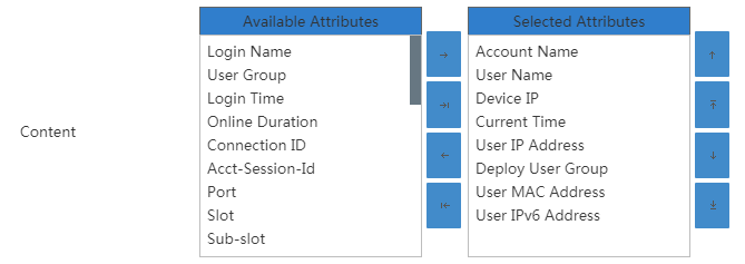
4. Click OK.
Adding a user notification of SYSLOG type
1. On the User Notification Parameters list page, click Add.
2. Select SYSLOG from the Notification Type list.
3. Configure the following parameters:
¡ Event—Select an event that triggers the user notification. Options are Obtain Endpoint IP, User Logon, Authentication Failure, Accounting Start, and User Logoff.
¡ Server IP Address—Enter the IP address of the third-party system.
¡ Server Port—Enter the port number to which the third-party system listens for UAM messages.
¡ SYSLOG Packet Header—Enter a syslog packet header string of 1 to 512 characters.
¡ Content—Configure the content that includes the attributes to send to the third-party system through syslog packets. Edit the text in the left column, and then select an attribute in the right column to insert the attribute to the text. For example, enter Your name is in the left column and select User Name in the right column. If the user name is abc, UAM sends a user notification with the content Your name is abc to the third-party system.
4. Click OK.
Adding a user notification of UDP type
1. On the User Notification Parameters list page, click Add.
2. Select UDP from the Notification Type list.
3. Configure the following parameters:
¡ Event—Select an event that triggers the user notification. Options are Obtain Endpoint IP, User Logon, Authentication Failure, Accounting Start, and User Logoff.
¡ Server IP Address—Enter the IP address of the third-party system.
¡ Server Port—Enter the port number to which the third-party system listens for UAM messages.
¡ Content—Configure the content that includes the attributes to send to the third-party system through UDP packets. Edit the text in the left column, and then select an attribute in the right column to insert the attribute to the text. For example, enter Your name is in the left column and select User Name in the right column. If the user name is abc, UAM sends a user notification with the content Your name is abc to the third-party system.
4. Click OK.
Adding a user notification of Proprietary type
1. On the User Notification Parameters list page, click Add.
2. Select Proprietary from the Notification Type list.
3. Configure the following parameters:
¡ Event—Select an event that triggers the user notification. Options are Obtain Endpoint IP, User Logon, Authentication Failure, Accounting Start, and User Logoff.
¡ Server IP Address—Enter the IP address of the third-party system.
¡ Server Port—Enter the port number to which the third-party system listens for UAM messages.
¡ Shared Key—Enter the key that UAM and the third-party system use to authenticate each other. The value must be the same as the configuration of the third-party system.
¡ Confirm Shared Key—Enter the same shared key as the value in the Shared Key field.
4. Click OK.
Adding a user notification of Custom type
1. On the User Notification Parameters list page, click Add.
2. Select Custom from the Notification Type list.
3. Configure the following parameters:
¡ Event—Select an event that triggers the user notification. Options are Obtain Endpoint IP, User Logon, Authentication Failure, Accounting Start, and User Logoff.
¡ Content—Specify the attributes UAM sends to the third-party system through packets in customized packet format.
4. Click OK.
After adding a user notification of Custom type, perform the following tasks:
1. Implement the sendMessage method defined in the com.h3c.imc.acm.notify.ThirdNotify interface.
2. Use a text editor to open the file acmNotifyPluginCfg.xml in the \uamthirdpartyauth\conf directory of the IMC installation path and configure the class that implements the com.h3c.imc.acm.notify.ThirdNotifyImpl interface.
3. Compile com.h3c.imc.acm.notify.ThirdNotifyImpl into a class file, generate a .jar package, and store the package in the \uamthirdpartyauth\repository\imc\jars directory of the IMC installation path.
4. Restart the uamThirdAuth process.
Modifying a user notification
1. Access the User Notification Parameters list page.
2. Click the Modify icon ![]() for a user notification.
for a user notification.
The page for modifying the user notification opens.
3. Modify the user notification parameters.
For more information about the parameter description, see "Adding user notifications."
4. Click OK.
Deleting a user notification
1. Access the User Notification Parameters list page.
2. Click the Delete icon ![]() for a user notification.
for a user notification.
A confirmation dialog box opens.
3. Click OK.
Configuring client anti-crack
Restrictions control the use of network resources by normal authenticated users. However, unauthorized users bypass authentication and access control by cracking, tempering and spoofing clients, so their use of network resources is not restricted.
To prevent unauthorized access to the network, UAM works with the iNode management center to provide the anti-crack function for iNode PC clients. An iNode PC client that is customized in the iNode management center has a dictionary file and UAM also obtains a dictionary file from the iNode management center. During the user authentication, UAM verifies the consistency of the two dictionary files. If they do not match, authentication fails.
For this function to operate correctly, select iNode Client Only in the UAM access policy configuration, and enable Client Protection Against Cracks in system parameter configuration.
This function is available only for 802.1X and portal access.
The client anti-crack function protects the iNode PC client in various scenarios when an iNode management center is added to UAM.
Viewing the iNode management center list
1. Click the User tab.
2. From the navigation tree, select User Access Policy > Service Parameters > System Settings.
The list includes all the system settings.
3. Click the Configure
icon ![]() for Client Anti-Crack.
for Client Anti-Crack.
The Client Anti-Crack page displays all iNode management centers that are added to UAM.
¡ Management Center IP Address—IP address of the iNode management center.
¡ Remarks—Remarks of the iNode management center.
¡ Status—Status of the iNode management center. The Valid state indicates the iNode PC clients installed or upgraded using the management center support the client anti-crack function. The Invalid state indicates the iNode PC clients installed or upgraded using the management center do not support the client anti-crack function.
¡ Modify—Click the Modify icon ![]() to modify settings of
the iNode management center.
to modify settings of
the iNode management center.
¡ Delete—Click the Delete icon ![]() to delete the iNode management center.
to delete the iNode management center.
Adding an iNode management center
1. On the Client Anti-Crack page, click Add.
The Add iNode Management Center page opens.
2. Configure the following parameters:
¡ Management Center IP Address—Enter the IP address of the host installed where the iNode management center is installed. The IP address cannot conflict with any existing IP addresses. If the host has multiple IP addresses, enter any address that can communicate with UAM.
¡ Remarks—Enter remarks for the iNode management center. A detailed description is helpful for an operator to maintain the management center.
3. Click OK.
A newly added iNode management center is in invalid state. To make the management center valid, click Validate on the Client Anti-Crack page. This operation validates all management centers on the list. Then, UAM performs the following operations:
· Gets the dictionary file for the new iNode management center.
· Deletes dictionary files of the existing valid iNode management centers, and then gets new dictionary files for them.
If UAM fails to get the dictionary file of a new iNode management center, iNode PC clients customized by the iNode management center cannot pass authentication.
Modifying the iNode management center description
1. On the Client Anti-Crack page, click the Modify icon ![]() for the iNode
management center you want to modify.
for the iNode
management center you want to modify.
The Modify iNode Management Center page opens.
2. Modify the remarks for the iNode management center. The Management Center IP Address parameter cannot be modified.
3. Click OK.
Enabling client anti-crack
When the iNode management center is enabled, the client anti-crack function protects the iNode PC client in the following scenarios:
· The iNode PC client is installed using the installation program customized by the management center.
· The iNode PC client is installed using an installation program customized by another management center, but the program version is the same as this management center.
· The iNode PC client is upgraded using the upgrade program customized by the management center.
· The iNode PC client is upgraded using an upgrade program customized by another management center, but the program version is the same as this management center.
On the Client Anti-Crack page, click Validate to validate the iNode management center.
After you add, modify, or delete an iNode management center, click Validate on the Client Anti-Crack page to make the configuration take effect.
Deleting the iNode management center
After the iNode management center is deleted, the client anti-crack function no longer takes effect on the following iNode PC clients if UAM does not have any management center of the same version:
· iNode PC clients installed using the installation program customized by the management center.
· iNode PC clients installed using an installation program customized by another management center but the program version is the same as this management center.
· iNode PC clients upgraded using the upgrade program customized by the management center.
· iNode PC clients upgraded using an upgrade program customized by another management center but the program version is the same as this management center.
To delete the iNode management center:
1. On the Client Anti-Crack page, click the Delete icon ![]() .
.
A confirmation dialog box opens.
2. Click OK.
Configuring proxy server detection settings
A host configured with a proxy server forwards a large number of received packets to other hosts. UAM works with the iNode client to detect proxy servers:
1. UAM defines the proxy server detection parameters, and sends the parameters to the iNode client. Proxy server detection parameters include:
¡ Forwarded packet threshold
¡ External network segments excluded from detection
¡ Internal network segments to be detected
2. The iNode client monitors its PC based on these parameters. If the packet forwarding rate of the PC exceeds the forwarded packet threshold, the iNode client determines that a proxy server is configured on the PC.
The other two proxy server detection parameters, external network segments excluded from detection and internal network segments to be detected, affect calculation of the forwarded packet threshold in the following ways:
· If external network segments excluded from detection is configured, the iNode client does not collect the packets sourced from these network segments to the authentication network card.
· If internal network segments under detection is configured, the iNode client also collects the packets forwarded to these network segments by all network cards.
· If neither parameter is configured, the iNode client collects all packets from the external network to the authentication network card and all packets forwarded by all network cards to the network segment where the local PC is located.
For example, if the IP address of the iNode client PC is 192.168.1.1/24, the iNode client collects all packets sent from the external network to the authentication network card and all packets forwarded by all network cards to the network segment 192.168.1.0/24.
The proxy server detection parameters take effect only for the users who disable proxy server.
To configure proxy server detection parameters:
3. Click the User tab.
4. From the navigation tree, select User Access Policy > Service Parameters > System Settings.
The list includes all the system settings.
5. Click the Configure
icon ![]() for Proxy Server Detection Settings.
for Proxy Server Detection Settings.
6. Enter the forwarded packet threshold (%).
7. Configure the external network segments excluded from detection.
You can exclude up to 32 external network segments from proxy server detection. The external network segments excluded from detection cannot overlap with each other, and cannot overlap with internal network segments to be detected.
8. To exclude external network segments from proxy server detection:
a. Click Add in the External Network Segments Excluded from Detection field.
A dialog box for adding a network segment opens. The network type is External Network Segments Excluded from Detection, and cannot be modified.
b. Enter the IP address and select the mask length.
The two parameters jointly determine the network segment. After the mask length is selected, the mask is automatically populated to be consistent with the mask length and cannot be modified.
c. Enter the network segment description for easy maintenance.
d. Click OK.
e. Click the Modify
icon ![]() for the network segment you want to modify.
for the network segment you want to modify.
A dialog box for modifying the network segment opens.
f. Repeat steps b to e to modify the network segment, or skip to step g.
g. Click the Delete
icon ![]() for a network segment
to delete an undesired network segment.
for a network segment
to delete an undesired network segment.
9. Configure internal network segments under detection.
You can configure up to 32 internal network segments for proxy server detection. The internal network segments cannot overlap with each other, and cannot overlap with the external network segments excluded from detection.
a. Click Add in the Internal Network Segments Under Detection field.
A dialog box for adding a network segment opens. The network type is Internal Network Segments Under Detection, and cannot be modified.
b. Enter the IP address and select the mask length.
The two parameters jointly determine the network segment. After the mask length is selected, the mask is automatically populated to be consistent with the mask length and cannot be modified.
c. Enter the network segment description for easy maintenance.
d. Click OK.
e. Click the Modify
icon ![]() for the network segment you want to modify.
for the network segment you want to modify.
A dialog box for modifying the network segment opens.
f. Repeat steps b to e to modify the network segment.
g. Click the Delete
icon ![]() for a network segment
to delete an undesired network segment.
for a network segment
to delete an undesired network segment.
10. Click OK.
Configuring the third-party authentication system
After the third-party authentication function is enabled, an access user using the Internet service suffix will be authenticated by the third-party system based on the bound phone number and password after passing UAM authentication. The user cannot access the target network if the user failed RADIUS authentication of the third-party system or the user is not configured with a bound phone number.
To configure the third-party authentication system:
1. Click the User tab.
2. From the navigation tree, select User Access Policy > Service Parameters > System Settings.
The list includes all the system settings.
3. Click the Configure icon![]() for Third-Party
Authentication System.
for Third-Party
Authentication System.
The Third-Party Authentication System page opens.
4. Configure the following parameters:
¡ Enable Third-Party Authentication System Settings—Select this option to enable the third-party authentication function.
¡ IP Address—Enter the IP address of the third-party system.
¡ Authentication Port—Enter the third-party system's port that monitors RADIUS authentication packets.
¡ Accounting Port—Enter the third-party system's port that monitors RADIUS accounting packets.
¡ Shared Key—Enter the shared key used to authenticate UAM and the third-party system. This key must be the same as the key configured in the third-party system.
¡ Confirm Shared Key—Confirm the shared key.
¡ Intranet Service Suffix—Enter an intranet service suffix. An access user using this service suffix needs to be authenticated by UAM only.
¡ Internet Service Suffix—Enter an Internet service suffix. An access user using this service suffix will be authenticated by the third-party system based on user telephone number and password after passing UAM authentication. The Internet service suffix must be different from the intranet service suffix.
|
|
NOTE: To add or modify the user telephone number or password: · An operator configures a telephone number or password for a user when adding, importing, or modifying an access user account. See "Managing access users." · A user logs in to the self-service center to modify the telephone number or password. See "Modifying account information." |
¡ Wired Accounting Service Suffix—This is an accounting-related parameter. Leave it empty.
5. Click OK.
Configuring the cell phone number ranges
After the cell phone number ranges are configured, only the phone numbers within the ranges can be bound to users.
Viewing the Cell Phone Number Range List
1. Click the User tab.
2. From the navigation tree, select User Access Policy > Service Parameters > System Settings.
The list includes all the system settings.
3. Click the Configure icon![]() for Cell Phone Number Range Settings.
for Cell Phone Number Range Settings.
Cell Phone Number Range List contents
¡ Cell Phone Number Range—First N digits of phone numbers. The cell phone numbers beginning with these digits belong to the same cell phone number range.
¡ Description—Description of the cell phone number range.
¡ Modify—Click the Modify icon ![]() to modify the cell
phone number range.
to modify the cell
phone number range.
¡ Delete—Click the Delete icon ![]() to delete the cell phone number range.
to delete the cell phone number range.
Adding the cell phone number range
1. On the Cell Phone Number Range list, click Add.
2. Configure the following parameters:
¡ Cell Phone Number Range—Enter the first N digits of cell phone numbers. The cell phone numbers beginning with these digits belong to the same cell phone number range.
¡ Description—Enter a description for the cell phone number range.
3. Click OK.
Importing cell phone number ranges in batches
1. On the Cell Phone Number Range List, click Batch Import.
2. Click Browse for the Import File field to select the file storing the cell phone number range.
The import file must be in TXT or CSV format.
3. Select Column Separator. Options are Space, TAB, comma (,), pound sign (#), and dollar sign ($).
A .csv file must use commas as column separators.
4. Click Next. The Batch Import Cell Phone Number Range page opens. UAM automatically resolves the number of columns contained in the imported file and displays the result in the drop down list for each parameter.
Configure the following parameters:
¡ Cell Phone Number Range—Automatically read the cell phone number range of the N column from the imported file.
¡ Description—Select Not Imported and then enter a description, or select a column from the list to use as the description for the cell phone number range. N varies according to actual situations. If you enter a description, all imported cell phone number ranges use this description.
5. Click Preview.
The Preview Import Result window displays the first 10 records in the imported file.
6. Click Close.
7. On the Batch Import Cell Phone Number Range page, click OK. The cell phone number ranges are imported.
8. Verify the imported cell phone number ranges.
The Operation Result page displays the number of imported cell phone number ranges and number of cell phone number ranges failed to be imported.
If there are cell phone number ranges failed to be imported, click Download to download or open the error logs that record the cell phone number ranges and failure causes.
9. Click Back.
Modifying the description of the cell phone number range
1. On the Cell Phone
Number Range List, click the Modify icon ![]() .
.
2. Modify the description of the cell phone number range:
¡ Cell Phone Number Range—Cannot be modified.
¡ Description—Enter a new description for the cell phone number range. A detailed description is helpful for an operator to maintain the cell phone number range.
3. Click OK.
Deleting the cell phone number range
The cell phone number range used by an access user cannot be deleted.
To delete the cell phone number range:
1. On the Cell Phone
Number Range List, click the Delete icon ![]() .
.
A confirmation dialog box opens.
2. Click OK.
Configuring user binding information
UAM automatically learns binding parameter settings in the first successful authentication of an access user account as the bound values in the following conditions:
· Binding parameters are configured in an access policy.
· No values of the binding parameters are configured for an access user account to which this access policy is assigned.
For more information about automatic learning, see "Configuring user access policies."
Viewing user binding information
1. Click the User tab.
2. From the navigation tree, select User Access Policy > Service Parameters > System Settings.
The list includes all the system settings.
3. Click the Configure
icon ![]() for User Binding Configuration.
for User Binding Configuration.
The User Binding Information page opens.
User Binding Information list content
¡ User Binding Information—Name of the binding parameter for automatic learning. For more information about binding parameters, see "Managing ordinary access users."
¡ Auto-Learned Number—Maximum number of values that can be automatically learned for the binding parameter.
Setting the auto-learned number of binding parameters
By default, UAM records only one value for each binding parameter during automatic learning. You can modify the auto-learned numbers of binding parameters:
1. Access the User Binding Information page.
2. On the user binding information list, click the number in the Auto-Learned Number column for a binding parameter.
3. Enter a number in the field, and then click a blank area to quit the edit mode.
4. Repeat step 2 and step 3 to set other binding parameters.
5. Click OK.
Configuring alias authentication
Alias authentication enables users to provide an enrolled email address, phone number, or identity number, rather than the user name, for authentication. This authentication method applies to UAM local authentication, BYOD authentication, self-service center login, and other authentication scenarios.
Configuration restrictions and guides
When you configure the alias authentication configuration, use the following restrictions and guidelines:
· The alias attribute value cannot be a system-reserved name such as anonymous, byodanonymous, or computer.
· If the value of an alias attribute contains the at sign (@), use the character string before the at sign for alias authentication. For example, use someUser in the email attribute value [email protected] for alias authentication.
· Make sure the alias attribute value is unique for each access user. If multiple accounts have the same alias attribute value, the first account that passes alias authentication will be automatically bound to the alias attribute value for future alias authentication.
· Make sure an alias attribute value is different from any of the access users. If the value is the same as an access user, UAM always considers it as an access user and does not perform alias authentication.
· Manually validate new entries by clicking Validate in the alias authentication configuration. Without manual validation, the new entries will take effect at the daily validation time.
· If a platform user is associated with multiple access user accounts or guest accounts, the alias authentication configuration takes effect only on the account with the earliest creation time. If the account is canceled later, the alias authentication configuration takes effect on the next account with the earliest creation time.
· When a user moves from one user group to another, the alias authentication configuration of the new group automatically applies to the user. For example, information about an account includes phone number 15001230123 and email address [email protected]. The system-defined user group Ungrouped uses the phone number as the alias attribute value and user group Manager uses the email address as the alias attribute value. When the account moves from group Ungrouped to group Manager, the alias attribute value is changed to abc. The original alias attribute value 15001230123 is cleared for the user.
Accessing the alias authentication configuration list page
1. Click the User tab.
2. From the navigation tree, select User Access Policy > Service Parameters > System Settings.
3. On the System Settings page, click the Configure icon ![]() for the Alias Authentication Configuration item.
for the Alias Authentication Configuration item.
The Alias Authentication Configuration list displays all user groups configured with alias authentication configuration and the attributes to be used for alias authentication. User groups not on the list use the default alias authentication configuration.
Alias authentication configuration list contents
¡ User Group—A group of users who can perform alias authentication.
¡ Alias—User attributes that can be used for alias authentication.
¡ Modify—Click the Modify icon ![]() to modify user attributes for alias authentication.
to modify user attributes for alias authentication.
¡ Delete—Click the Delete icon ![]() to delete an alias
authentication configuration entry.
to delete an alias
authentication configuration entry.
¡ Add—Click Add to add an alias authentication configuration entry.
¡ Refresh—Click Refresh to refresh the alias authentication configuration list.
¡ Validate—Click
the Validate icon ![]() to make all changes to the alias
authentication configuration list take effective immediately.
to make all changes to the alias
authentication configuration list take effective immediately.
¡ Daily Validation Time (O'clock of Every Day)—Time when changes to the alias authentication configuration list automatically take effect. If an entry is configured later than the specified time, it will take effect at the validation time the next day.
Adding an alias authentication configuration entry
The alias authentication configuration is added by user group.
To add an alias authentication configuration entry:
1. Access the alias authentication configuration list page.
2. Click Add.
The Add Alias Authentication Configuration page opens.
3. Click the User Group icon ![]() , select a user
group, and then click OK.
, select a user
group, and then click OK.
4. In the Select Alias Attributes area, perform the following actions as needed:
¡ Select
one or more fields in the Available Attributes list, and then click the Copy icon ![]() to copy the
fields to the Alias Attributes list.
to copy the
fields to the Alias Attributes list.
¡ Click
the Copy all icon ![]() to move all fields
in the Available Attributes list to the Alias Attributes list.
to move all fields
in the Available Attributes list to the Alias Attributes list.
¡ Select
one or more fields in the Alias Attributes list,
and then click the Remove
icon ![]() to remove the
fields.
to remove the
fields.
¡ Click the Remove all icon ![]() to remove all fields from the Alias Attributes
list.
to remove all fields from the Alias Attributes
list.
|
|
NOTE: An alias attribute replaces the account name for alias authentication. It can be an enrolled email address, phone number, or identity number. The user additional information, such as the nickname, can also be used as an alias attribute. For more information about configuring user additional information, see HPE Intelligent Management Center v7.3 Enterprise and Standard Platform Administrator Guide. |
5. Click OK.
6. To make the new configuration take effect immediately, click Validate.
The new configuration also automatically takes effect at the specified time every day.
Modifying an alias authentication configuration entry
1. Access the alias authentication configuration list page.
2. Click the Modify
icon ![]() for an alias authentication configuration
entry.
for an alias authentication configuration
entry.
3. Modify the alias attributes. For more information, see "Adding an alias authentication configuration entry."
4. Click OK.
5. To make the modified configuration take effect immediately, click Validate.
Deleting an alias authentication configuration entry
1. Access the alias authentication configuration list page.
2. Click the Delete
icon ![]() for an alias authentication configuration entry.
for an alias authentication configuration entry.
A confirmation dialog box opens.
3. Click OK.
Modifying the daily validation time
Changes to the alias authentication configuration list automatically take effect at the specified time every day if they are not manually validated. To make these changes take effect immediately, click Validate.
To modify the daily validation time:
1. Access the alias authentication configuration list page.
2. Click Modify next to the Daily Validation Time (O'clock of Every Day) field.
3. On the Modify Alias Configuration Validation Time page, enter an integer in the range of 0 to 23.
4. Click OK.
Configuring a certificate
For information about configuring a certificate, see "Configuring certificate authentication."
Configuring client upgrade in UAM
UAM enables you to manage upgrade tasks for the iNode PC clients and iNode MC.
Managing iNode PC client upgrade tasks
The EAD solution supports the following methods for iNode PC client upgrade:
· Manual upgrade—Endpoint users can obtain the new version of iNode client from a network administrator to replace the existing iNode client on the Windows PCs.
· Automatic upgrade—Operators can enable client version upgrade or schedule customization upgrade tasks in the iNode PC management center, or configure client upgrade tasks in UAM.
The iNode management center can automatically upgrade the version or configuration of iNode PC client on Windows PCs. For more information, see the iNode management center help topic on client upgrade management.
The client upgrade tasks can be used to upgrade the client version or configuration, or to install new patches for the client automatically.
The following information describes management of client upgrade tasks in UAM for the iNode PC client.
Accessing the client upgrade task list page
1. Click the User tab.
2. From the navigation tree, select User Access Policy > Service Parameters > Client Upgrade.
The System Settings list displays all client upgrade tasks.
Client upgrade task list contents
¡ Task Name—Name of the client upgrade task. Click the name of a task to view its details.
¡ Version—Client version.
¡ File Name—Name of the client upgrade file.
¡ Upgrade Type—Client update type. Options are Force, Optional, Immediate Upgrade, Forced Upgrade - Next Startup Installation, and Immediate Upgrade - Next Startup Installation.
- Force—Displays a message when the user passes authentication, notifying the user of a forcible client upgrade that will occur within 2 hours. Endpoint users cannot cancel the upgrade.
- Optional—Displays a dialog box within 2 hours after the user passes authentication, allowing the user to upgrade the iNode client or ignore the upgrade.
- Immediate Upgrade—Indicates that the client will be upgraded immediately after the user passes authentication.
- Forced Upgrade - Next Startup Installation—Downloads the client upgrade package at a random time in 2 hours after the user comes online, and then automatically installs the upgrade at the next startup of the client. Endpoint users cannot cancel the upgrade.
- Immediate Upgrade - Next Startup Installation—Downloads the client upgrade package immediately after the user comes online, and then automatically installs the upgrade at the next startup of the client. Endpoint users cannot cancel the upgrade.
¡ Download Rate Limit—Upper rate limit for a user to download the client upgrade file, in Kb/s.
¡ Upgrade Type—Client upgrade type. The value can be Version Upgrade, Configuration Upgrade, or Patch Upgrade.
¡ Custom Time—When the upgrade type is Version Upgrade or Patch Upgrade, this field is empty. When the upgrade type is Configuration Upgrade, this field displays the time when the configuration was customized.
¡ Modify—Click the Modify icon ![]() to modify the client upgrade task.
to modify the client upgrade task.
¡ Delete—Click the Delete icon ![]() to delete the client upgrade task.
to delete the client upgrade task.
3. To view the latest client upgrade tasks, click Refresh.
Viewing the client upgrade task details
1. Access the client upgrade task list page.
2. Click the name link of a client upgrade task.
The page displays detailed information about the client upgrade task, including the following:
¡ Task Name—Name of the client upgrade task.
¡ Upgrade Type—Client update type. Options are Force, Optional, Immediate Upgrade, Forced Upgrade - Next Startup Installation, and Immediate Upgrade - Next Startup Installation.
- Force—Displays a message when the user passes authentication, notifying the user of a forcible client upgrade that will occur within 2 hours. Endpoint users cannot cancel the upgrade.
- Optional—Displays a dialog box within 2 hours after the user passes authentication, allowing the user to upgrade the iNode client or ignore the upgrade.
- Immediate Upgrade—Indicates that the client will be upgraded immediately after the user passes authentication.
- Forced Upgrade - Next Startup Installation—Downloads the client upgrade package at a random time in 2 hours after the user comes online, and then automatically installs the upgrade at the next startup of the client. Endpoint users cannot cancel the upgrade.
- Immediate Upgrade - Next Startup Installation—Downloads the client upgrade package immediately after the user comes online, and then automatically installs the upgrade at the next startup of the client. Endpoint users cannot cancel the upgrade.
¡ Upgrade Object—Type of client to be upgraded: PC Client or Mobile Client. Only iNode PC clients support the Forced Upgrade - Next Startup Installation and Immediate Upgrade - Next Startup Installation upgrade types.
¡ Download Rate Limit—Upper rate limit for a user to download the client upgrade file, in Kb/s.
¡ Client Upgrade File—File used for client upgrade.
¡ Third-Party Server URL—URL of a third-party server that stores the file for client upgrade. If this field is empty, the client downloads the upgrade file from UAM.
¡ Upgrade Type—Client upgrade type. The value can be Version Upgrade, Configuration Upgrade, or Patch Upgrade.
¡ Custom Time—Time when the configuration upgrade task was customized. This parameter is available only when the upgrade type is Configuration Upgrade.
¡ Task Description—Description of the task.
¡ By User/By User Group—Either of these two fields is displayed.
- By User—The upgrade task takes effect only on the users in the list.
- By User Group—The upgrade task takes effect only on the users in the selected groups.
3. To return to the client upgrade task list page, click Back.
Adding a client version upgrade task
1. Access the client upgrade task list page.
2. Click Add and select Version Upgrade from the shortcut menu.
The Add Client Version Upgrade Task page opens.
3. Configure the following parameters:
¡ Task Name—Enter the task name, which must be unique in UAM.
¡ Upgrade Type—Select a client update type from the list. Options are Force, Optional, Immediate Upgrade, Forced Upgrade - Next Startup Installation, and Immediate Upgrade - Next Startup Installation.
- Force—Displays a message when the user passes authentication, notifying the user of a forcible client upgrade that will occur within 2 hours. Endpoint users cannot cancel the upgrade.
- Optional—Displays a dialog box within 2 hours after the user passes authentication, allowing the user to upgrade the iNode client or ignore the upgrade.
- Immediate Upgrade—Indicates that the client will be upgraded immediately after the user passes authentication.
- Forced Upgrade - Next Startup Installation—Downloads the client upgrade package at a random time in 2 hours after the user comes online, and then automatically installs the upgrade at the next startup of the client. Endpoint users cannot cancel the upgrade.
- Immediate Upgrade - Next Startup Installation—Downloads the client upgrade package immediately after the user comes online, and then automatically installs the upgrade at the next startup of the client. Endpoint users cannot cancel the upgrade.
¡ Upgrade Object—Select PC Client from the list. Only iNode PC clients support the Forced Upgrade - Next Startup Installation and Immediate Upgrade - Next Startup Installation upgrade types.
¡ Download Rate Limit—Set the upper rate limit for a user to download the client upgrade file, in Kb/s. The value range is 10 to 1024.
¡ Client Upgrade File—Click Browse to select an upgrade file.
¡ Third-Party Server URL—Specify the URL of a third-party server that stores the file for client upgrade. If this field is empty, the client downloads the upgrade file from UAM.
¡ Task Description—Enter a description for the task.
¡ User Selection Mode—Select one mode when adding or modifying the client upgrade task.
- By User—When you select this option, the Selected Access Users list is displayed. Click Select. Query the access users and select one or more access users. Click OK. One user can be selected by only one task. Access users that have been selected by other tasks are not displayed.
- By User Group—When you select this option, the user group tree is displayed. Select one or more user groups to which the client upgrade task applies. The task applies to all users in the selected groups, but it does not apply to users in the parent or subgroup of the selected groups. One user group can be assigned to only one client upgrade task. The groups that have been assigned to other client upgrade tasks are unavailable.
|
|
IMPORTANT: · If you do not select any access user or user group, the client upgrade task does not take effect. · An access user and the user group it belongs to can be assigned to different client upgrade tasks. If the assigned tasks are of the same type, only the upgrade task assigned to the access user takes effect. |
4. Click OK.
Adding a client configuration upgrade task
1. Access the client upgrade task list page.
2. Click Add and select Configuration Upgrade from the shortcut menu.
The Add Client Configuration Upgrade Task page opens.
3. Configure the client configuration upgrade task parameters. For information about configuring the parameters, see "Adding a client version upgrade task." Make sure the file selected for the Client Upgrade File field supports client configuration upgrade.
Adding a client patch upgrade task
1. Access the client upgrade task list page.
2. Click Add and select Patch Upgrade from the shortcut menu.
The Add Client Patch Upgrade Task page opens.
3. Configure the client patch upgrade task parameters. For information about configuring the parameters, see "Adding a client version upgrade task." Make sure the file selected for the Client Upgrade File field supports client patch upgrade.
Modifying a client upgrade task
Client upgrade tasks can be modified even when they are being executed. The modifications do not affect the client upgrade files being downloaded.
To modify a client upgrade task:
1. Access the client upgrade task list page.
2. Click the Modify
icon ![]() of the upgrade task you want to modify.
of the upgrade task you want to modify.
3. Modify the client upgrade task parameters.
The Task Name, Upgrade Object, and Client Upgrade File cannot be modified. For more information about the parameter description, see "Adding a client version upgrade task."
4. Click OK.
Deleting a client upgrade task
Deleting an ongoing client upgrade task can affect client upgrade if the client upgrade file is being downloaded. However, client upgrade can carry out normally for users with the complete client upgrade file downloaded.
To delete a client upgrade task:
1. Access the client upgrade task list page.
2. Click the Delete
icon ![]() for the client upgrade
task you want to delete.
for the client upgrade
task you want to delete.
A confirmation dialog box opens.
3. Click OK.
Managing iNode MC upgrade tasks
The BYOD solution supports the following methods for iNode MC upgrade:
· Manual upgrade—Endpoint users can download the latest version of iNode MC from the Apple App Store or the Google Play Store to replace the existing iNode client on the iOS and Android endpoint.
· Automatic upgrade—Operators can configure a client version upgrade task in UAM to upgrade the version of iNode MC on all online iOS and Android endpoints.
Accessing the client upgrade task list page
See "Accessing the client upgrade task list page."
Viewing the client upgrade task details
1. Access the client upgrade task list page.
2. Click the name of a client version upgrade task for iNode MC.
The page displays detailed information about the client upgrade task, including the following:
¡ Mobile Client OS—Operating system on which the iNode MC runs.
¡ Default Mobile Client Upgrade Task—Whether or not the task is set as the default mobile client upgrade task. The default mobile client upgrade task is used by all mobile clients that access the network through a VPN connection.
For information about other parameters, see "Viewing the client upgrade task details."
Adding a client version upgrade task
1. Access the client upgrade task list page.
2. Click Add and select Client Version from the shortcut menu.
The Add Client Version Upgrade Task page opens.
3. Configure the following parameters:
¡ Task Name—Enter the task name, which must be unique in UAM.
¡ Upgrade Type—Select a client update type from the list. Options are Force, Optional, Immediate Upgrade, Forced Upgrade - Next Startup Installation, or Immediate Upgrade - Next Startup Installation.
- Force—Displays a message when the user passes authentication, notifying the user of a forcible client upgrade that will occur within 2 hours. Endpoint users cannot cancel the upgrade.
- Optional—Displays a dialog box within 2 hours after the user passes authentication, allowing the user to upgrade the iNode client or ignore the upgrade.
- Immediate Upgrade—Immediately upgrades the iNode client after the user passes authentication.
- Forced Upgrade - Next Startup Installation—Downloads the client upgrade package at a random time in 2 hours after the user comes online, and then automatically installs the upgrade at the next startup of the client. Endpoint users cannot cancel the upgrade.
- Immediate Upgrade - Next Startup Installation—Downloads the client upgrade package immediately after the user comes online, and then automatically installs the upgrade at the next startup of the client. Endpoint users cannot cancel the upgrade.
¡ Upgrade Object—Select Mobile Client from the list. Only iNode PC clients support the Forced Upgrade - Next Startup Installation and Immediate Upgrade - Next Startup Installation upgrade types.
¡ Mobile Client OS—Select the operating system on which the mobile client runs. Options are Android and iOS.
¡ Default Mobile Client Upgrade Task—Select this option to set the task as the default mobile client upgrade task. The default mobile client upgrade task is used by all mobile clients that access the network through a VPN connection.
¡ Download Rate Limit—Set the upper rate limit for a user to download the client upgrade file, in Kb/s. The value range is 10 to 1024.
¡ Client Upgrade File—Click Browse to select an upgrade file.
¡ Third-Party Server URL—Specify the URL of a third-party server that stores the file for client upgrade. If this field is empty, the client downloads the upgrade file from UAM.
¡ Task Description—Enter a description for the task.
¡ User Selection Mode—Select one mode when adding or modifying the client upgrade task.
- By User—When you select this option, the Selected Access Users list is displayed. Click Select. Query the access users and select one or more access users. Click OK. One user can be selected by only one task. Access users that have been selected by other tasks are not displayed.
- By User Group—When you select this option, the user group tree is displayed. Select one or more user groups to which the client upgrade task applies. The task applies to all users in the selected groups, but it does not apply to users in the parent group or subgroup of the selected groups. One user group can be assigned to only one client upgrade task. The groups that have been assigned to other client upgrade tasks are unavailable.
|
|
IMPORTANT: · If you do not select any access user or user group, the client upgrade task does not take effect on any user or user group. · An access user and the user group it belongs to can be assigned to different client upgrade tasks. If the assigned tasks are of the same type, only the upgrade task assigned to the access user takes effect. |
4. Click OK.
Modifying a client upgrade task
Mobile client upgrade tasks can be modified even when they are being executed. The modifications do not affect the client upgrade files being downloaded to endpoints.
To modify a client upgrade task:
1. Access the client upgrade task list page.
2. Click the Modify
icon ![]() for the client upgrade task you want to modify.
for the client upgrade task you want to modify.
3. Modify the client upgrade task parameters.
The Task Name, Upgrade Object, and Client Upgrade File cannot be modified. For more information about the parameter description, see "Adding a client version upgrade task."
4. Click OK.
Deleting a client upgrade task
See "Deleting a client upgrade task."
Configuring smart device client upgrade
The smart device client upgrade function upgrades the version of iNode MC 7.0.6 or earlier. To use this function, enable the policy server first (see "Configuring policy server parameters").
To configure smart device client upgrade:
1. Click the User tab.
2. From the navigation tree, select User Access Policy > Service Parameters > Smart Device Client Upgrade Configuration.
The smart device client upgrade configuration page opens.
3. Configure the following parameters:
¡ Enable Smart Device Client Upgrade—Select this option to enable smart device client upgrade.
Other parameters take effect only when this option is selected.
¡ Target Version—Enter the client version after upgrade. For example, to upgrade a portal client to iNode MC 7.0.6 (V7.00-0006), enter V7.00-0006.
¡ Upgrade URL—Enter the URL that stores the iNode client upgrade file, which can be an Internet URL or a URL of the internal network of an enterprise.
4. Click OK.
Configuring unified authentication
Unified authentication integrates access authentication and application authentication. With unified authentication, users need only one authentication process to access the network and various Web application systems. Without unified application, they must use multiple authentication processes.
Unified authentication applications include:
· Web Application System > Portal
· Web Application System > Self-Service
· Portal > Web Application System
· iNode Client Shortcut Configuration
Configuring Web Application System > Portal
Web Application System > Portal authentication combines Web application system authentication with portal authentication. Users passing this type of authentication can access all networks that require portal authentication.
To configure Web Application System > Portal:
1. Click the User tab.
2. From the navigation tree, select User Access Policy > Service Parameters > Unified Authentication.
3. Click the Configure
icon ![]() for Web Application System > Portal.
for Web Application System > Portal.
4. Select Enable.
5. Enter and confirm a shared key to secure communication between the Web application system and the portal server.
6. Enter the timestamp valid time, which determines how long the Web application system and the portal server trust each other after a successful communication between them. During the timestamp valid time period, the Web application system believes that the portal server is secured.
7. Enter a URL in the Redirect to URL after Portal Authentication field in the format of http://aabbcc/dd. The URL opens after portal authentication, whether the portal authentication process succeeds.
8. Click OK.
The configuration takes effect one minute later.
Configuring Web Application System > Self-Service
Web Application System > Self-Service authentication provides a link to the Self-Service Center on the Web application system page. When a user passes Web application system authentication, the Self-Service Center page opens.
To configure Web Application System > Self-Service:
1. Click the User tab.
2. From the navigation tree, select User Access Policy > Service Parameters > Unified Authentication.
3. Click the Configure
icon ![]() for Web Application System > Self-Service.
for Web Application System > Self-Service.
4. Select Enable.
5. Enter and confirm a shared key to secure the communication between the Web application system and the user self-service server.
6. Select the check modes for opening the URL of the Self-Service Center after Web application system authentication.
Options are Check password and Check timestamp. You can select either one or both.
7. Enter the timestamp valid time, which determines how long the Web application system and the user self-service server trust each other after a successful communication between them.
During the timestamp valid time period, the Web application system believes that the user self-service server is secured. This parameter is required if Check timestamp is selected for Check Mode.
8. Click OK.
The configuration takes effect one minute later.
Configuring Portal > Web Application System
Portal > Web Application System authentication combines portal authentication with Web application system application. Users passing this type of authentication can directly access the Web application system.
This type of unified authentication applies to two scenarios: the entrance type scenario and the non-entrance type scenario.
To configure Portal > Web Application System:
1. Click the User tab.
2. From the navigation tree, select User Access Policy > Service Parameters > Unified Authentication.
3. Click the Configure
icon ![]() for Portal > Web Application System.
for Portal > Web Application System.
For the entrance type scenario:
a. Select Enable.
b. Enter and confirm a shared key to secure the communication between the Web application system and the portal server.
c. Configure whether to display the Portal authentication only string on the portal authentication page.
If the string is displayed, the user can select whether to perform automatic authentication for the Web application system after portal authentication.
d. Configure whether or not the Portal authentication only option is selected on the portal authentication page by default.
e. The options Selected by default and Not selected by default appear only when Display "Portal authentication only" is selected.
f. Enter a URL in the Redirect to URL after Portal Authentication field in the format of http://aabbcc/dd.
The URL opens after successful identity authentication through the portal webpage or iNode DC client.
For the non-entrance type scenario:
g. Select Enable.
h. Enter and confirm a shared key to secure the communication between the Web application system and the portal server.
i. Enter a URL in the Redirect to URL after Portal Authentication field in the format of http://aabbcc/dd.
The URL opens after successful identity authentication through the portal webpage or iNode DC client.
4. Click OK.
The configuration takes effect one minute later.
Configuring iNode client shortcuts
This function allows the iNode client to automatically perform authentication for Web application systems after the security check is completed. The iNode client also displays links to the Web application systems and icons for common application programs on the left navigation tree.
The user can click a link to automatically log in to the associated Web application system, or click an icon to execute the associated application program.
Accessing the iNode client shortcut configuration list page
1. Click the User tab.
2. From the navigation tree, select User Access Policy > Service Parameters > Unified Authentication.
3. Click the Configure
icon ![]() for iNode Client Shortcut Configuration.
for iNode Client Shortcut Configuration.
The iNode Client Shortcut Configuration list displays all shortcut configuration entries.
iNode client shortcut configuration list contents
¡ Configuration Name—Name of the iNode client shortcut configuration.
¡ Status—Whether the iNode client shortcut is enabled.
¡ Modify—Click
the Modify icon ![]() to modify the iNode client shortcut configuration.
to modify the iNode client shortcut configuration.
¡ Delete—Click
the Delete icon ![]() to delete the
iNode client shortcut configuration.
to delete the
iNode client shortcut configuration.
Viewing the iNode client shortcut configuration details
1. Access the iNode Client Shortcut Configuration page.
2. Click the name link of a configuration entry.
The page displays detailed information about the iNode client shortcut configuration.
Basic Configuration area
¡ Configuration Name—Name of the iNode client shortcut configuration.
¡ Status—Whether the iNode client shortcut is enabled.
Web Application area
¡ Name—Name of the Web application system, which is displayed on the left navigation tree of the iNode client.
¡ URL—URL of the Web application system.
¡ Check Mode—Check mode for automatically opening the URL of the Web application system after the security check.
¡ Run Type—Run type for the Web application system during iNode client authentication. Options include:
- Do not run—Prohibits automatic execution of the Web application system during authentication, but allows manual execution.
- Run after identity authentication—Allows the Web application system to run immediately after identity authentication is passed.
- Run after security check—Allows the Web application system to run only when security policies apply and the security check is completed, regardless of the security check result.
- Run after security check is passed—Allows the Web application system to run only when security policies apply and the security check is passed.
- Run after security check is failed—Allows the Web application system to run only when security policies apply and the security check is failed.
The last three options appear only after the EAD component is deployed.
Executable Programs area
¡ Name—Program name.
¡ Executable Command—Command to run the program.
¡ Run Type—Run type for the program during iNode client authentication. Options include:
- Do not run—Prohibits automatic execution of the program during authentication, but allows manual execution.
- Run after identity authentication—Allows the program to run immediately after identity authentication is passed.
- Run after security check—Allows the program to run only when security policies apply and the security check is completed, regardless of the security check result.
The last option is displayed only after the EAD component is deployed.
User Selection Mode area
¡ Users—When this option is selected, the iNode client shortcut configuration takes effect on selected users.
¡ User Groups—When this option is selected, the iNode client shortcut configuration takes effect on users in selected user groups.
¡ All User—When this option is selected, the iNode client shortcut configuration takes effect on all users.
Adding an iNode client shortcut configuration entry
1. Access the iNode Client Shortcut Configuration page.
2. Click Add.
3. Enter a unique name for the configuration and select Enable.
4. Enter and confirm a shared key to secure the communication between the iNode client and each Web application system.
5. Configure Web application systems:
a. Click Add on the Web Application System list.
A dialog box for adding a Web application system opens.
b. Enter the Web application system name.
The name is displayed on the left navigation tree of the iNode client.
c. Enter a URL in the format of http://aabbcc/dd.
The URL links to the Web application system.
d. Select the check modes for opening the URL of the Web application system after the security check.
Options are Check password and Check timestamp. You can select either one or both.
e. Select the run type for the Web application system during iNode client authentication.
Options are:
- Do not run—Prohibits automatic execution of the Web application system during authentication, but allows manual execution.
- Run after identity authentication—Allows the Web application system to run immediately after identity authentication is passed.
- Run after security check—Allows the Web application system to run only when security policies apply and the security check is completed, regardless of the security check result.
- Run after security check is passed—Allows the Web application system to run only when security policies apply and the security check is passed.
- Run after security check is failed—Allows the Web application system to run only when security policies apply and the security check is failed.
The last three options appear only after the EAD component is deployed.
f. Click OK.
g. Repeat the previous steps to configure more Web application systems.
You can configure up to 32 Web application systems.
h. Click the Delete icon ![]() to delete the associated Web application system.
to delete the associated Web application system.
i. Click the Up icon ![]() or
the Down icon
or
the Down icon ![]() to move the associated Web application system upwards or downward
on the left navigation tree of the iNode client. If multiple Web application
systems are the same run type except Do not run, only the system on the
top of the navigation tree is automatically opened.
to move the associated Web application system upwards or downward
on the left navigation tree of the iNode client. If multiple Web application
systems are the same run type except Do not run, only the system on the
top of the navigation tree is automatically opened.
6. Configure executable programs:
a. Click Add on the Executable Programs list.
A dialog box for adding an executable program opens.
b. Enter the program name. The name is displayed on the left navigation tree of the iNode client.
c. Enter the command to run the program.
d. Select the run type for the program during iNode client authentication. Options are:
- Do not run—Prohibits automatic execution of the program during authentication, but allows manual execution.
- Run after identity authentication—Allows the program to run immediately after identity authentication is passed.
- Run after security check—Allows the program to run only when security policies apply and the security check is completed, regardless of the security check result.
The last option is displayed only after the EAD component is deployed.
e. Click OK.
f. Repeat the previous steps to configure more executable programs.
You can configure up to 32 programs.
g. Click the Delete icon ![]() to delete the associated program.
to delete the associated program.
h. Click the Up icon ![]() or
the Down icon
or
the Down icon ![]() to move the associated program
upwards or downward on the left navigation tree of the iNode client. If
multiple executable programs are the same run type except Do not run, only
the program on the top of the navigation tree is automatically opened.
to move the associated program
upwards or downward on the left navigation tree of the iNode client. If
multiple executable programs are the same run type except Do not run, only
the program on the top of the navigation tree is automatically opened.
Configure the scope to apply the iNode client shortcut configuration:
i. From the User Selection list, select the mode to specify the scope: Users, User Groups, or All User.
j. If Users is selected, click Select in the Selected Access Users list, query and select access users, and then click OK.
k. If User Groups is selected, select the user groups from the group tree. Use the Include Parent and Subgroups option to facilitate group selection.
7. Click OK.
The configuration takes effect one minute later.
|
|
NOTE: · If an access user and its user group are configured with an iNode client shortcut, the shortcut configuration takes effect on only the access user. · To add a configuration entry that applies to all users, make sure the configuration list does not contain entries that apply to specific users or user groups. |
Modifying an iNode client shortcut configuration entry
1. Access the iNode Client Shortcut Configuration page.
2. Click the Modify
icon ![]() of the entry you want to modify.
of the entry you want to modify.
3. Modify parameters for the iNode client shortcut configuration. For more information about the parameter description, see "Adding an iNode client shortcut configuration entry."
4. Click OK.
Deleting an iNode client shortcut configuration entry
1. Access the iNode Client Shortcut Configuration page.
2. Click the Delete
icon ![]() for the entry you want to delete.
for the entry you want to delete.
A confirmation dialog box opens.
3. Click OK.
Validating system settings manually
UAM system settings take effect automatically. However, if a system setting fails to take effect because of a network fault, an operator can manually validate the setting after the network recovers.
To validate a system setting, click the User tab and select User Access Policy > Service Parameters > Validate.
Using the user self-service
The Self-Service Center in UAM allows access users and device management users to maintain their accounts themselves, reducing the workload of UAM operators.
To access the Self-Service Center login page, enter http://IP:port/selfservice or https://IP:port/selfservice in the address bar of the Web browser. The IP address and port number must be the same as the settings of the installed User Selfservice Management component. PC users automatically access the PC version of the Self-Service Center. Pad and phone users automatically access the touch version of the Self-Service Center. Users can switch between versions by clicking the PC or touch version link.
Using the PC version of the Self-Service Center
The following information describes services provided by the PC version of the Self-Service Center except the guest preregistration service. For more information about guest preregistration, see "Managing preregistered guests in the self-service center (by a guest manager)."
Preregistering access users
Endpoint users can preregister access user accounts only when User Preregistration is enabled on the System Parameters page.
The operator must register the access user after an endpoint user has preregistered the access user account. For more information, see "Managing preregistered users."
To preregister access users:
1. Enter http://ip:port/selfservice in the address bar to access the self-service center.
The IP address refers to that of the self-service center server, and the port refers to the listening port of the self-service center.
2. Click the Preregister User link on the login page.
The page for preregistering access users opens. If the administrator selects Disable for User Preregistration, the Preregister User link does not exist.
3. Configure basic information:
¡ User Name—Enter the name of the terminal user.
¡ Identity Number—Enter the identity number of the terminal user.
¡ Contact Address—Enter the contact address of the terminal user.
¡ Telephone—Enter the telephone number of the terminal user.
¡ Email—Enter the email address of the terminal user.
4. Configure access information:
¡ Account Name—Enter the account name.
¡ User Password—Enter the password of the account.
¡ Confirm Password—Enter the same password of the account again.
¡ User IP—Enter the IP address often used by the user to access the device. The value can be used for access user registration when the operator intends to apply for a service that requires a user IP to be bound to the user.
¡ NIC MAC—Enter the MAC address often used by the user to access the device. The value can be used for access user registration when the operator intends to apply for a service that requires a MAC address to be bound to the user.
¡ Verification Code—Enter the verification code to prevent frequent registration.
¡ User IPv6 Address—Enter the IPv6 address of the endpoint that is frequently used for network access. The value can be referenced in access user registration when the operator intends to assign the user a service that requires an IPv6 address to be bound to the user.
6. To clear the fields, click Reset.
Maintaining accounts by access users
Retrieving an access user password
Access users can use the password retrieve function to retrieve forgotten passwords. LDAP users are not allowed to use this function because LDAP user passwords are saved in LDAP servers, and most LDAP servers do not allow UAM to obtain the passwords.
To retrieve an access user password:
1. On the Self-Service Center login page, click the Forget Password link.
2. On the User Authentication Info page, enter the account name and verification code.
UAM sends the account name and password to the email address that was set in the user basic information.
4. To clear the fields, click Reset.
5. Click Back to return to the Self-Service Center.
Logging in to the Self-Service Center
1. Enter the account name, password, and verification code on the login page.
2. Select Ordinary user from the User Type list.
3. Click Login.
The Self-Service Center supports on-demand LDAP synchronization. If a user account does not exist in UAM, UAM forwards the user's authentication request to the LDAP server.
¡ If the user passes LDAP authentication, UAM allows the user to log in to the Self-Service Center and synchronizes the LDAP user.
¡ If the user fails to pass LDAP authentication, UAM prohibits the user from logging in to the Self-Service Center.
Viewing account information
From the navigation tree, select User Information > Query User Information.
The page displays detailed information about the login user.
· Basic Information
¡ User Name—Name of the associated platform user.
¡ Identity Number—Identity number of the associated platform user.
¡ Contact Address—Contact address of the associated platform user.
¡ Telephone—Telephone number of the associated platform user.
¡ Email—Email address of the associated platform user.
· User Access Information
¡ Account Name—Account name of the access user. The access user uses this name for authentication.
¡ Account Status—Current status of the account. This field must display normal. Otherwise, the access user cannot log in to the self-service center.
¡ Start Time—Time when the access user becomes valid. An empty field indicates that the access user is already valid.
¡ End Time—Time when the access user will expire. If this field is empty, the access user never expires.
¡ Max. Concurrent Logins—Maximum number of concurrent login users. If this field is empty, the concurrent login user number is not limited.
¡ Max. Idle Time—Maximum idle time that the access user can be online. The access user is forced to log off when the idle time expires. If this field is empty, the access user can always be online.
¡ LDAP Authentication—Whether or not LDAP authentication is enabled. If the value is Yes, UAM forwards the authentication request from the access user to the LDAP server. If the value is No, UAM authenticates the user locally.
¡ WLAN Cell Phone Number—Phone number to which the access user is bound. This field is displayed only when Third-Party Authentication System is enabled in the UAM system settings. For more information, see "Configuring the third-party authentication system."
· Binding Information area
¡ Device SN—Requires the access user to connect to the access device that has the specified sequence number.
¡ Computer Name—Name of the computer that the access user binds with. The access user can pass the authentication only if it uses a computer with this name. If this field is empty, the access user does not bind with any computer name.
¡ IMSI—IMSI of the computer to which the access user is bound.
¡ Windows Domain—Name of the Windows domain to which the computer used by the access user is bound. The access user can pass the authentication only if it uses a computer that joins or logs onto the domain. If this field is empty, the user does not bind with any Windows domain.
¡ Terminal IP—IPv4 address of the endpoint to which the access user is bound. Each entry on the list represents the IPv4 address of an endpoint bound to the access user. If a device has multiple IP addresses, use the IPv4 address of the corresponding endpoint in UAM.
¡ Terminal IPv6 Address—IPv6 address of the endpoint to which the access user is bound. Each entry on the list represents the IPv6 address of an endpoint bound to the access user. If a device has multiple IPv6 addresses, use the IPv6 address of the corresponding endpoint in UAM.
¡ Terminal MAC Address—MAC addresses of the endpoint to which the access user is bound. To pass authentication, an access user must use a MAC address on the list. Select the specified column number in the file as the bound MAC addresses.
· Subscribed Service Information
The list includes all services that are assigned to the user.
Modifying account information
1. From the navigation tree, select User Information > Update User Information.
2. Modify the following information:
¡ Identity Number—Enter a new identity number. The user must enter a non-existent identity number in UAM.
¡ WLAN Cell Phone Number—Enter a new phone number and click Obtain Verification Code. UAM sends the verification code to the cell phone through an SMS sender or modem.
¡ Verification Code—Enter the verification code received by the cell phone.
¡ WLAN Password—Enter a new phone password.
¡ Confirm Password—Enter the same password as the value in the WLAN Password field.
¡ Contact Address—Enter a new contact address.
¡ Telephone—Enter a new telephone number.
¡ Email—Enter a new email address.
The Account Name, Creation Date, Account Status, and User Name fields cannot be modified.
3. Click OK.
Changing a password
The following users are not allowed to change their passwords on the Self-Service Center:
· LDAP users.
· Access users that the operator disabled from changing passwords (when the operator added or modified the access users).
To change a password in the Self-Service Center:
1. From the navigation tree, select User Information > Modify Password.
This service is not available if your password cannot be changed.
2. Enter the old password, new password, and confirm password.
3. Click OK.
|
|
IMPORTANT: After a transparent authentication user modifies the password, UAM automatically removes the MAC-account binding for the user. The user must enter the username and password for next authentication. |
Viewing account online details
1. From the navigation tree, select Self-Service Lobby > Query Access Summary.
2. Configure the following query criteria:
¡ Query Period From/To—Enter the start
and end online time or click the Calendar icon ![]() to select the start and end
time. The time must be in the format YYYY-MM-DD.
to select the start and end
time. The time must be in the format YYYY-MM-DD.
¡ Service—Select a service from the list.
3. Click Query.
The list includes the user online details matching the query criteria.
Access Detail List contents
¡ Start Time—Time when the user starts to log online after it passes the authentication.
¡ Duration—Online duration for a login of the user.
¡ Outgoing Bytes—Uploaded bytes for a login of the user. The access device must support collecting statistics of uploaded bytes. If it is not supported, this field displays a hyphen (-).
¡ Incoming Bytes—Downloaded bytes for a login of the user. The access device must support collecting statistics of downloaded bytes. If it is not supported, this field displays a hyphen (-).
4. Click the Details
icon ![]() for the online terminal user to view the details.
for the online terminal user to view the details.
Query for Access Details parameters
¡ Start Time—Time when the user starts to log online after it passes the authentication.
¡ End Time—Time when the user logs off.
¡ Outgoing Bytes—Uploaded bytes for this login of the user. The access device must support collecting statistics of uploaded bytes. If not, this field displays a hyphen (-).
¡ Incoming Bytes—Downloaded bytes for this login of the user. The access device must support collecting statistics of downloaded bytes. If not, this field displays a hyphen (-).
¡ Duration—Online duration for this login of the user.
¡ User IP Address—IP address of the access user.
¡ User MAC Address—MAC address of the access user.
¡ User IPv6 Address—IPv6 address of the access user. This field is displayed only when IPv6 is enabled in the UAM system settings.
5. Click Back to return to Access Details List.
Viewing the online user list
The online user list displays online information for only the current login accounts.
To view the online user list:
1. Log in to the Self-Service Center.
2. From the navigation tree, select Self-Service Lobby > Online User List.
The Online User List displays the online account. If the concurrent online users can be more than one for an account, the list may display multiple online users using the same account name.
Online User List contents
¡ Account Name—Account name of the access user.
¡ Login Name—Login name that the access device sends to UAM, in the format account name@service extension.
¡ User Name—Name of the associated platform user.
¡ Service Name—Name of the service that the access user is using.
¡ Login Time—Time when the access user passed the authentication.
¡ Online Duration—Online duration of the access user.
¡ User IP Address—IPv4 address of the access user.
¡ User MAC Address—MAC address of the access user.
¡ User IPv6 Address—IPv6 address of the access user. This field is displayed only when IPv6 is enabled in the UAM system settings.
¡ Operation—Click the Clear online information link to clear the online information. This function is used when a logged-off user is still displayed online in UAM. Another endpoint user using the account cannot log in when Max. Concurrent Logins is set to 1. An access user can perform this function to manually clear online user information so that the user can normally access the network.
Viewing the FAQ and trouble report
When encountering a network problem, an endpoint user can log in to the Self-Service Center to check the FAQ. If the FAQ cannot help the user solve the problem, the user can use the trouble report function to report the problem to the operators.
For more information about checking the FAQ and trouble report, see "Managing trouble tickets in the Self-Service Center."
Managing endpoint devices
The Self-Service Center enables you to manage the user account to MAC address bindings. MAC addresses that are bound to endpoint user accounts can be used for transparent authentication.
The Endpoint Management module allows you to configure transparent authentication for endpoints. This function requires transparent authentication to be enabled in user endpoint settings.
Viewing the endpoint list
1. Log in to the self-service center.
2. From the navigation tree, select User Endpoint > Endpoint Management.
The list includes all endpoints that are uniquely identified by MAC addresses.
Endpoint list contents
¡ MAC Address—Endpoint MAC address.
¡ Service Name—Name of the access service used by the access user on the endpoint for transparent portal authentication for the first time. The endpoint is bound with the access user and the access service. The user is not required to provide the user name and password for subsequent network access from the endpoint. UAM performs authentication and authorization for the access user on the endpoint by using the bound access service.
¡ Vendor—Vendor of the endpoint.
¡ Endpoint Type—Type of the endpoint.
¡ Transparent Authentication—Whether transparent authentication is enabled for the endpoint device. For more information about configuring transparent authentication for an endpoint device, see "Enabling transparent authentication for endpoint devices" and "Disabling transparent authentication for endpoint devices."
¡ Modify—Click
the Modify icon ![]() to
modify the endpoint information.
to
modify the endpoint information.
Viewing endpoint device details
1. Access the endpoint list page.
2. Click the MAC address link of the endpoint device.
Endpoint device details
¡ MAC address—MAC address of the endpoint device.
¡ Description—Description of the endpoint device.
¡ Service Name—Name of the access service used by the access user on the endpoint for transparent portal authentication for the first time. The endpoint is bound with the access user and the access service. The user is not required to provide the user name and password for subsequent network access from the endpoint. UAM performs authentication and authorization for the access user on the endpoint by using the bound access service.
¡ Vendor—Vendor of the endpoint device.
¡ Endpoint Type—Type of the endpoint device.
¡ Transparent Authentication—Whether transparent authentication is enabled for the endpoint device. For more information about configuring transparent authentication for an endpoint device, see "Enabling transparent authentication for endpoint devices" and "Disabling transparent authentication for endpoint devices."
¡ Endpoint State—State of the endpoint: Normal or Lost. When an endpoint device is lost, the user can modify the state of the endpoint to lost, or informs the UAM administrator to modify the endpoint state. Only endpoints in normal state can access the network.
3. To return to the endpoint list page, click Back.
Binding a MAC address to the current user account
1. From the navigation tree, select Endpoint Management > Endpoint List.
The list includes all the MAC addresses bound to the current user account.
2. Click Add.
3. Enter a MAC address in the MAC Address field.
The MAC address must be a 12-digit hexadecimal number in the format of XXXXXXXXXXXX, XXXX-XXXX-XXXX, XX-XX-XX-XX-XX-XX, or XX:XX:XX:XX:XX:XX. X represents a number of 0 to 9 or a case-insensitive letter of A to F.
4. Enter a description for the MAC address to help distinguish MAC addresses.
5. Select the Enable Transparent Authentication option to enable transparent authentication for the MAC address.
6. Select the endpoint state. Only endpoints in normal state can access the network.
7. Click OK.
The newly added MAC address is bound to the current user account. Each MAC address can be bound to only one user account.
8. Repeat step 3 to step 7 to bind more MAC addresses to the user account. The maximum number of MAC addresses that can be bound to a user account depends on the user endpoint settings. For more information, see "Configuring user endpoint settings."
Modifying a MAC address bound to the current user account
1. From the navigation tree, select Endpoint Management > Endpoint List.
The page displays all the MAC address entries bound to the user account.
2. Click the Modify
icon ![]() for the MAC address you want to modify.
for the MAC address you want to modify.
3. Modify the parameters as needed. For more information, see "Binding a MAC address to the current user account."
Enabling transparent authentication for endpoint devices
1. From the navigation tree, select Endpoint Management > Endpoint List.
2. Select one or more endpoints for which you want to enable transparent authentication.
3. Click Enable Transparent Authentication.
A confirmation dialog box opens.
4. Click OK.
The Operation Result page displays the operation results. If failures occur, click the Download link to download or view the operation log.
Disabling transparent authentication for endpoint devices
1. From the navigation tree, select Endpoint Management > Endpoint List.
2. Select one or more endpoints for which you want to disable transparent authentication.
3. Click Disable Transparent Authentication.
A confirmation dialog box opens.
4. Click OK.
The Operation Result page displays the operation results. If failures occur, click the Download link to download or view the operation log.
Binding online endpoint devices to the current user account
1. Access the endpoint device list.
2. Select endpoint devices to be bound.
3. Click Bind Online Endpoint to bind the selected endpoint devices to the user account.
Make sure the endpoint MAC address is not empty. Otherwise, UAM cannot bind any endpoint devices to the user account.
Modifying an endpoint device bound to the current user account
1. Access the endpoint device list.
2. Click the Modify ![]() icon for the MAC address of the endpoint
device.
icon for the MAC address of the endpoint
device.
3. Modify the description of the MAC address to facilitate maintenance.
4. Enable or disable transparent authentication for the endpoint device as needed.
5. Modify the endpoint state. Only endpoint devices in normal state can access the network.
6. Click OK.
Deleting endpoints bound to the current user account
1. From the navigation tree, select Endpoint Management > Endpoint List.
2. Select the endpoints to be deleted.
3. Click Delete.
A confirmation dialog box opens.
4. Click OK.
Maintaining user information by device management users
1. On the login page, enter the account name, password, and verification code, select Device admin from the User Type list, and then click Login.
2. From the navigation tree, select User Information > Query User Information.
The page displays detailed information about the login user.
¡ Account Name—Account name used for the device management user to log into the device.
¡ Login Type—Application used for the management user to log in the device, which can be Telnet, FTP, SSH, or Terminal.
¡ EXEC Priority—Level of the command execution privilege assigned to the device management user. The value is an integer in the range of 0 to 15, and varies with device models. A greater value represents a higher privilege, which grants users to execute more commands. If the parameter is not configured, this field displays two consecutive hyphens (--), and the user can use the default level specified on the device.
¡ LDAP Authentication—Whether or not LDAP authentication is implemented for the device management user. If this field displays Yes, UAM forwards the user's authentication requests to an LDAP server. If this field displays No, UAM checks the validity for the user.
¡ Role Name—List of roles that are assigned to the user. This parameter is supported only on HP Comware and partial H3C devices.
¡ FTP Directory—Directory that the device management user can access after logging into the device. This field is displayed only when the Login Type is FTP. If this field displays two consecutive hyphens (--), no FTP directory is set and the user enters the default directory after logging into the device. This field is displayed only when the Login Type field is FTP.
¡ Host IP Address—IPv4 address range from which the device management user can log into the device. This field does not appear when the login type is Terminal.
¡ Device IP Address—Range of IPv4 addresses of the managed devices that the device management user can log in to.
3. From the navigation tree, select User Information > Modify Password to modify the password.
4. Enter the old password, new password, and confirm password.
5. Click OK.
Checking the FAQ
When encountering a network problem during accessing the device, a device management user can log in to the Self-Service Center to check the FAQ. For more information about FAQ, see "Using the user self-service."
Using the touch version of the Self-Service Center
Logging in to the Self-Service Center
To log in to the Self-Service Center, enter the account name, password, and verification code on the login page, and then tap Login.
The Self-Service Center supports on-demand LDAP synchronization. When the account name for self-service login does not exist in UAM, UAM forwards the user authentication request to the LDAP server. If the user passes authentication on the LDAP server, UAM allows the user to log in to the Self-Service Center and synchronizes the LDAP user. If the user fails to pass authentication on the LDAP server, UAM prohibits the user from logging in to the Self-Service Center.
The home page of the Self-Service Center includes the following areas:
· User information—Displays the account name, a Modify Profile link, and a Guest link. Tap Modify Profile to modify personal information. Tap Guest to manage guests.
· Function icons—Provides function icons. The access user can add or delete icons in the area.
· Online records—Displays the most recent five online records for the user.
· Menu—Includes Home, Service, Endpoint, and About options.
Customizing function icons
The home page contains the following function icons, which cannot be deleted:
· My Profile
· My Endpoint
· Modify Password
To customize function icons:
1. Tap More.
The customization page opens, including the following functions:
¡ Access Service
¡ Online Endpoint
¡ Access Record
2. Tap Add to display a function icon on the home page.
3. Tap Delete to hide a function icon from the home page.
4. Tap Close.
Maintaining personal information
Viewing online information
The home page displays online information for the current user, as shown in Figure 164.
Figure 147 Viewing online user information
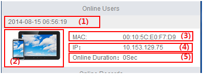
|
(1) Time when the user came online |
(2) Endpoint type |
|
(3) Endpoint MAC address |
(4) Endpoint IP address |
|
(5) Online duration |
|
Viewing the last online record
The home page displays the last online record when the current user is offline, as shown in Figure 165.
Figure 148 Viewing the last online record
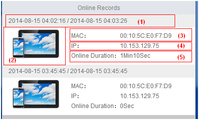
|
(1) Online/offline time |
(2) Endpoint type |
|
(3) Endpoint MAC address |
(4) Endpoint IP address |
|
(5) Online duration |
|
Viewing the online history
On the home page, view the online history for the current user by using one of the following methods:
· Tap Menu, and then select Service. Tap Access History.
· Tap the Access History icon. For information about displaying this function icon on the home page, see "Customizing function icons."
The online history includes online information for the last week or an earlier period, as shown in Figure 166.
Figure 149 Viewing the online history
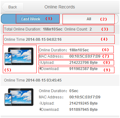
|
(1) Online records for the last week |
(2) Earlier online records |
|
(3) Total online duration and number of accesses for the last week |
(4) Online duration for a single access |
|
(5) Endpoint type |
(6) Online duration |
|
(7) Endpoint MAC address |
(8) Total upload bytes for a single access |
|
(9) Total download bytes for a single access |
|
Viewing the user profile
On the home page, tap My Profile to view information about the current user. The page includes the following areas and parameters:
· Personal Information area
¡ Account Name—Account name used for authentication or self-service login.
¡ Full Name—Name of the access user recorded in UAM.
¡ Identity Number—Identity number of the access user recorded in UAM.
¡ Contact Address—Contact address of the access user recorded in UAM.
¡ Telephone—Telephone number of the access user recorded in UAM.
¡ Email—Email address of the access user recorded in UAM.
· Account Information area
¡ Status—User account state. In Normal state, the user account can be used for authentication. In other state, the user account cannot be used for authentication.
¡ Validity Time/Expiration Time—Time range in which the user account is valid and can be used for authentication.
¡ Maximum Online Users—Maximum number of concurrent online users of the account. When this number is reached, no more users can access the network by using the account.
Modifying the user profile
1. Access the edit page by using one of the following methods:
¡ Tap Modify Profile.
¡ Tap My Profile, and then tap Modify.
2. Modify personal information.
3. Tap Done.
Viewing access service information
On the home page, view access service information for the access user by using one of the following methods:
· Tap Menu, and then select Service. Tap Access Service.
· Tap the Access Service icon. For information about displaying this function icon on the home page, see "Customizing function icons."
The page displays all access services and service suffixes assigned to the access user in UAM.
Maintaining endpoints
Viewing online endpoints
1. On the home page, tap Menu, and then select Service.
2. Tap Online Endpoint to view information about online endpoints, as shown in Figure 167.
Figure 150 Viewing online endpoint information
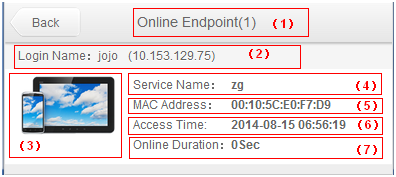
|
(1) Page title with the number of online endpoints |
(2) Login name and endpoint IP address |
|
(3) Endpoint type |
(4) Service used for authentication |
|
(5) Endpoint MAC address |
(6) Time when the user came online |
|
(7) Online duration |
|
Viewing endpoints
On the home page, view endpoint information for the access user by using one of the following methods:
· Tap the My Endpoint icon.
· Tap Menu, and then select Endpoint.
The endpoint page is shown in Figure 168.
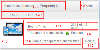
|
(1) Page title with the number of bound endpoints. |
(2) Tap Add to bind more endpoints. |
|
(3) Endpoint MAC address. |
(4) Endpoint type. |
|
(5) Time when the endpoint was bound. |
(6) Transparent MAC authentication state. |
|
(7) Configure MAC authentication state. |
(8) Tap Delete to unbind the endpoint. |
Binding endpoints to the access user
1. Access the endpoint page by using one of the following methods:
¡ Tap the My Endpoint icon.
¡ Tap Menu, and then select Endpoint.
2. To bind the endpoint to the access user, tap Bind Online Endpoint.
Make sure the endpoint MAC address is not empty. Otherwise, UAM cannot bind the endpoint to the access user.
3. To bind another endpoint to the access user:
a. Tap Add.
b. Enter an endpoint MAC address and a description, and then configure transparent MAC authentication.
c. Tap Done.
Unbinding an endpoint from the access user
1. Access the endpoint page by using one of the following methods:
¡ Tap the My Endpoint icon.
¡ Tap Menu, and then select Endpoint.
2. Tap Delete for an endpoint.
A confirmation dialog box opens.
3. Tap OK.
Changing the password
1. Access the change password page by using one of the following methods:
¡ Tap the Modify Password icon.
¡ Tap Menu, and then select Service. Tap Modify Password.
2. Enter the new password, and confirm the password.
3. Tap Done.
Retrieving an access user's password
Access users can retrieve forgotten passwords. LDAP users cannot retrieve passwords because the LDAP server that stores the passwords might not allow UAM to obtain the passwords.
To retrieve the password of an access user:
1. On the login page of the Self-Service Center, tap Forget Password.
2. On the User Authentication Info page, enter the account name and verification code.
3. Tap Retrieve Password.
UAM sends the account name and password to the email address that was set in the user basic information.
4. To clear the fields, tap Reset.
5. Tap Back to return to the login page of the Self-Service Center.
Viewing the About information
On the home page, tap Menu, and then select About to view the version and copyright of the Self-Service Center.
Returning to the home page
To return to the home page, tap Menu, and then select Home.
Exiting the Self-Service Center
On the home page, tap Logout.
Using the Guest Center
A guest manager can log in to the Guest Center to manage guests.
To open the Guest Center login page:
1. Open the Web browser.
2. Enter http://ip:port/guest or https://ip:port/guest in the address bar.
The string ip is the IP address of the server with the User Selfservice Management component installed. The string port is the HTTP or HTTPS service port number provided by the User Selfservice Management component.
Using the PC version of the Guest Center
The http://ip:port/guest address automatically navigates you to the PC version of the Guest Center. The Guest Center provides the following functions:
· Preregistering guests (see "Preregistering a guest on the Guest Center login page").
· Managing preregistered guests (see "Managing preregistered guests in the Guest Center").
· Managing registered guests (see "Managing registered guests in the Guest Center").
· Retrieving password (see "Retrieving an access user password").
· Viewing FAQs (see "Managing FAQs in the Guest Center").
Using the touch version of the Guest Center
Accessing the guest management page
Access the guest management page by using one of the following methods:
· On the home page, tap Guest in the user information area.
· On the login page, tap Guest Manager Self-Service. Enter the account name and password, and then tap Login.
Approving a guest
1. Access the guest management page.
2. On the preregistered guest list, tap a guest.
The guest information page opens.
3. Tap Approve or Approve & Generate QR Code.
If you tap Approve, UAM formally registers the guest.
If you tap Approve & Generate QR Code, UAM formally registers the guest and this page displays a QR code. Then the guest can scan the QR code for network access.
Registering a guest
1. Access the guest management page.
2. Tap Guest Registration.
The guest registration page opens.
3. On the Regular Registration tab, enter the following guest information:
¡ Guest name
¡ Identity number
¡ Contact address
¡ Telephone
¡ Account name
¡ Password
4. Select Generate QR Code to display a QR code after the guest registration. Then the guest can scan the QR code for network access. If this option is not selected, the guest must enter the account name and password for network access.
5. Tap Register.
Registering a guest by mobile number
1. Access the guest management page.
2. Tap Guest Registration.
The guest registration page opens.
3. Tap Mobile Registration.
4. Enter a mobile number.
5. Select Generate QR Code to display a QR code after the guest registration. Then the guest can scan the QR code for network access. If this option is not selected, the guest must access an authentication URL for network access.
6. Tap Register.
UAM sends an SMS message that includes the authentication URL to the mobile number.
Performing a quick guest registration
1. Access the guest management page.
2. Tap Guest Registration.
The guest registration page opens.
3. Tap Quick Registration.
4. Tap Yes.
UAM registers the guest and displays a QR code on the page. Then the guest can scan the QR code for network access.
Changing the theme
1. Access the guest management page.
2. Tap About.
3. Tap Theme.
4. Select a theme.
5. Tap OK.
The new theme applies to the guest manager self-service center.
Exiting the guest manager self-service center
To exit the guest manager self-service center, tap About on the guest management page, and then tap Logout.