- Table of Contents
- Related Documents
-
| Title | Size | Download |
|---|---|---|
| 01-Service chain configuration | 117.76 KB |
Contents
Configuring an inter-device service chain
Display and maintenance commands for service chains
Service chain configuration examples
Example: Configuring an inter-device service chain
Configuring service chains
About service chains
The service chain technology is used to guide network service packets through service nodes. The technology is used in combination with software defined network (SDN) for service orchestration. Service packets in a service chain are forwarded and processed by service nodes in a specific order.
Inter-device service chain
Inter-device service chains apply only to VXLAN packets. Service chain policies are used to control packets in the Overlay network as follows:
1. Encapsulate IP packets into VXLAN packets for service chain processing.
2. Deliver the VXLAN packets through all service nodes in a service chain.
You can deploy service chain policies for different tenant applications from a VCF controller through OpenFlow.
For more information about VXLAN, see VXLAN Configuration Guide. For more information about VCF controllers, see the VCF controller configuration guide.
|
|
NOTE: A service chain applied to contexts of different users on a device is an inter-device service chain. |
Network model
As shown in Figure 1, based on different tenant applications, the VCF controller deploys service chain policies to the service nodes through OpenFlow for the following purposes:
· Match VXLAN packets in the Overlay network. Only matching packets are forwarded into the service chain.
· Make sure the matching packets traverse all service nodes in the service chain.
Figure 1 Inter-device service chain network diagram
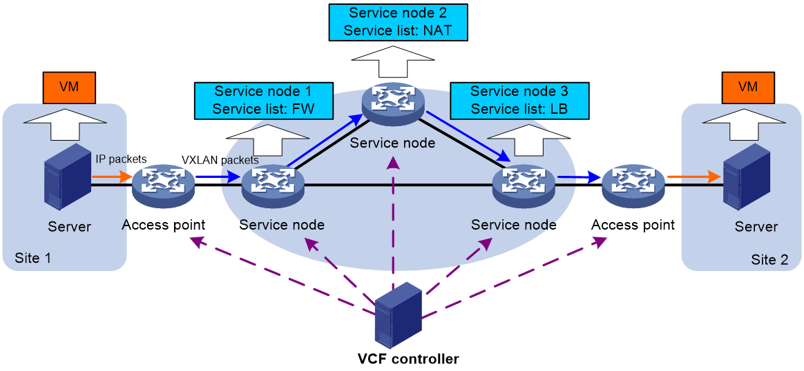
Access point
An access point is a VXLAN tunnel end point (VTEP) that processes packets based on the service chain policy deployed by a VCF controller.
Service node
A service node is a physical device or a network function virtualization (NFV) device that applies services in a service list to the received VXLAN packets. An inter-device service chain can have multiple service nodes.
A service list on a service node specifies the types and order of services to be applied to the VXLAN packets. Available services include FW and LB.
An inter-device service chain supports the following special types of service nodes:
· Head node—The first service node in a service chain that processes the VXLAN packets.
· End node—The last service node in a service chain that processes the VXLAN packets.
Packet format
Inter-device service chain packets use the VXLAN header. Figure 2 shows the format of a service chain packet.
Figure 2 Service chain packet format
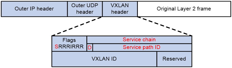
The service chain modifies the following fields in a VXLAN header:
· Flags—If the S bit is 1, the Service chain field is valid. If the S bit is 0, the Service chain field is invalid.
· Service chain—A 24-bit field that includes the D bit and service path ID. If the D bit is 0, the packet is a forward packet. If the D bit is 1, the packet is a backward packet. The 23-bit service path ID is used to identify an inter-device service chain.
Operating mechanisms
An inter-device service chain processes a packet in the following procedure:
1. Based on the service chain policy deployed from the VCF controller, the access point in the inbound packet direction (inbound access point) processes the received packet as follows:
a. Encapsulates the packet into a VXLAN packet.
b. Forwards the VXLAN packet to the head node.
2. The head node compares the service path ID in the VXLAN header of the received packet with the path IDs of the service chains.
¡ If the packet matches a service chain, the head node forwards the packet into the service chain.
¡ If the packet does not match any service chain, the head node performs a VXLAN forwarding for the packet.
3. After a service node completes processing the received VXLAN packet, it forwards the packet in one of the following ways:
¡ If the IP address of the next service node is specified, the node forwards the packet to the next service node.
¡ If no next service node address is specified, the current service node is the end node. The service node removes the service path ID field from the packet and forwards the packet to the access point in the outbound packet direction (outbound access point).
4. The outbound access point decapsulates the VXLAN packet and performs an IP forwarding for the packet.
Configuring an inter-device service chain
You can configure an inter-device service chain through VCF controller deployment or at the CLI. This document describes inter-device service chain configuration at the CLI. As a best practice, use a VCF controller to deploy the service chain configuration through a NETCONF session. For more information about the VCF controller deployment method, see the VCF controller configuration guide.
Configuring an access point
You can only use a VCF controller to deploy the service chain configuration to a device that acts as an access point. For more information, see the relevant VCF controller manuals.
Configuring a service node
Restrictions and guidelines
If the device is the end node in an inter-device service chain, you only need to specify the previous service node address.
If the device is the head node in an inter-device service chain, you only need to specify the next service node address.
Procedure
1. Enter system view.
system-view
2. Create a service chain and enter its view.
service-chain path path-id
3. Specify the next service node address for forward packets.
next-service-node ip-address
By default, no next service node address is specified for forward packets.
4. Specify the previous service node address for backward packets.
previous-service-node ip-address
By default, no previous service node address is specified for backward packets.
5. Create a service node and enter its view.
service function function-id
6. Configure a service list.
service list { fw | lb } *
Display and maintenance commands for service chains
Execute display commands in any view.
|
Command |
|
|
Display service chain information. |
display service-chain path { path-id | all } |
|
Display service chain statistics. |
display service-chain statistics |
Service chain configuration examples
Example: Configuring an inter-device service chain
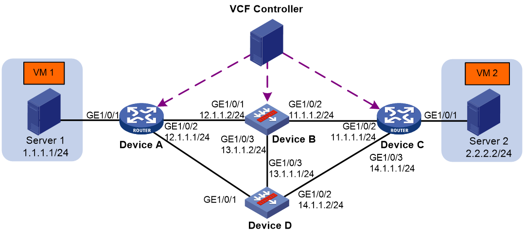
Network configuration
As shown in Figure 3, Device A and Device C act as access points. Device B and Device D act as service nodes. VM 1 and VM 2 are internal network devices. The inter-device service chain processes the traffic from VM 1 to VM 2 as follows:
1. On Device B, apply the FW service to the traffic.
2. On Device D, apply the LB service to the traffic.
Procedure
1. Configure IP addresses for interfaces to ensure IP connectivity between neighboring nodes. (Details not shown.)
2. Use a VCF controller to deploy service chain policies to Device A and Device C and label the VXLAN packets from VM 1 to VM 2 with service path ID 1. (Details not shown.)
3. Configure Device B:
a. Assign IP addresses to interfaces:
# Assign an IP address to interface GigabitEthernet 1/0/1.
<DeviceB> system-view
[DeviceB] interface gigabitethernet 1/0/1
[DeviceB-GigabitEthernet1/0/1] ip address 12.1.1.2 24
[DeviceB-GigabitEthernet1/0/1] quit
# Assign IP addresses to other interfaces in the same way. (Details not shown.)
b. Add interfaces to security zones.
[DeviceB] security-zone name trust
[DeviceB-security-zone-Trust] import interface gigabitethernet 1/0/1
[DeviceB-security-zone-Trust] import interface gigabitethernet 1/0/2
[DeviceB-security-zone-Trust] import interface gigabitethernet 1/0/3
[DeviceB-security-zone-Trust] quit
c. Configure settings for routing.
This example configures a static route, and the next hop in the route is 12.1.1.1.
[DeviceB] ip route-static 1.1.1.0 24 12.1.1.1
d. Configure a security policy:
# Configure a rule named trust-trust to permit the packets from VM 1 to VM 2.
[DeviceB] security-policy ip
[DeviceB-security-policy-ip] rule name trust-trust
[DeviceB-security-policy-ip-1-trust-untrust] source-zone trust
[DeviceB-security-policy-ip-1-trust-untrust] destination-zone trust
[DeviceB-security-policy-ip-1-trust-untrust] source-ip-subnet 1.1.1.0 24
[DeviceB-security-policy-ip-1-trust-untrust] destination-ip-subnet 2.2.2.0 24
[DeviceB-security-policy-ip-1-trust-untrust] action pass
[DeviceB-security-policy-ip-1-trust-untrust] quit
e. Configure service chain settings:
# Create service chain 1 and enter its view.
[DeviceB] service-chain path 1
# Specify the next service node address as 20.1.1.1, which is the loopback interface address of Device D. The loopback interface is specified as the VXLAN tunnel source interface.
[DeviceB-spath1] next-service-node 20.1.1.1
# Create service node 1.
[DeviceB-spath1] service function 1
# Create a service list that includes the FW service.
[DeviceB-spath1-func1] service list fw
4. Configure Device D:
a. Assign IP addresses to interfaces:
# Assign an IP address to interface GigabitEthernet 1/0/2.
<DeviceB> system-view
[DeviceB] interface gigabitethernet 1/0/1
[DeviceB-GigabitEthernet1/0/1] ip address 12.1.1.2 24
[DeviceB-GigabitEthernet1/0/1] quit
<DeviceD> system-view
[DeviceD] interface gigabitethernet 1/0/2
[DeviceD-GigabitEthernet1/0/2] ip address 14.1.1.2 24
[DeviceD-GigabitEthernet1/0/2] quit
# Assign IP addresses to other interfaces in the same way. (Details not shown.)
b. Add interfaces to security zones.
[DeviceD] security-zone name trust
[DeviceD-security-zone-Trust] import interface gigabitethernet 1/0/2
[DeviceD-security-zone-Trust] import interface gigabitethernet 1/0/3
[DeviceD-security-zone-Trust] quit
c. Configure settings for routing.
This example configures a static route, and the next hop in the route is 14.1.1.1.
[DeviceD] ip route-static 2.2.2.0 24 14.1.1.1
d. Configure a security policy:
# Configure a rule named trust-trust to permit the packets from VM 1 to VM 2.
[DeviceD] security-policy ip
[DeviceD-security-policy-ip] rule name trust-trust
[DeviceD-security-policy-ip-1-trust-untrust] source-zone trust
[DeviceD-security-policy-ip-1-trust-untrust] destination-zone trust
[DeviceD-security-policy-ip-1-trust-untrust] source-ip-subnet 1.1.1.0 24
[DeviceD-security-policy-ip-1-trust-untrust] destination-ip-subnet 2.2.2.0 24
[DeviceD-security-policy-ip-1-trust-untrust] action pass
[DeviceD-security-policy-ip-1-trust-untrust] quit
e. Configure service chain settings:
# Create service chain 1 and enter its view..
[DeviceD] service-chain path 1
# Specify the previous service node address as 20.1.1.2, which is the loopback interface address of Device B. The loopback interface is specified as the VXLAN tunnel source interface.
[DeviceD-spath1] previous-service-node 20.1.1.2
# Create service node 1.
[DeviceD-spath1] service function 1
# Create a service list that includes the LB service.
[DeviceD-spath1-func1] service list lb
Verifying the configuration
# Verify the following information: (Details not shown.)
· VXLAN packets from VM 1 to VM 2 are labeled with the path ID of the service chain.
· The FW and LB services are applied to the packets in sequential order.
